Raytheon IIS ARTU Air-Ground Radio System User Manual installation manual part one
Raytheon Company Air-Ground Radio System installation manual part one
UserManual.wiki
>
Raytheon IIS
>
ARTU User Manual
>
installation manual part one
Contents
1.
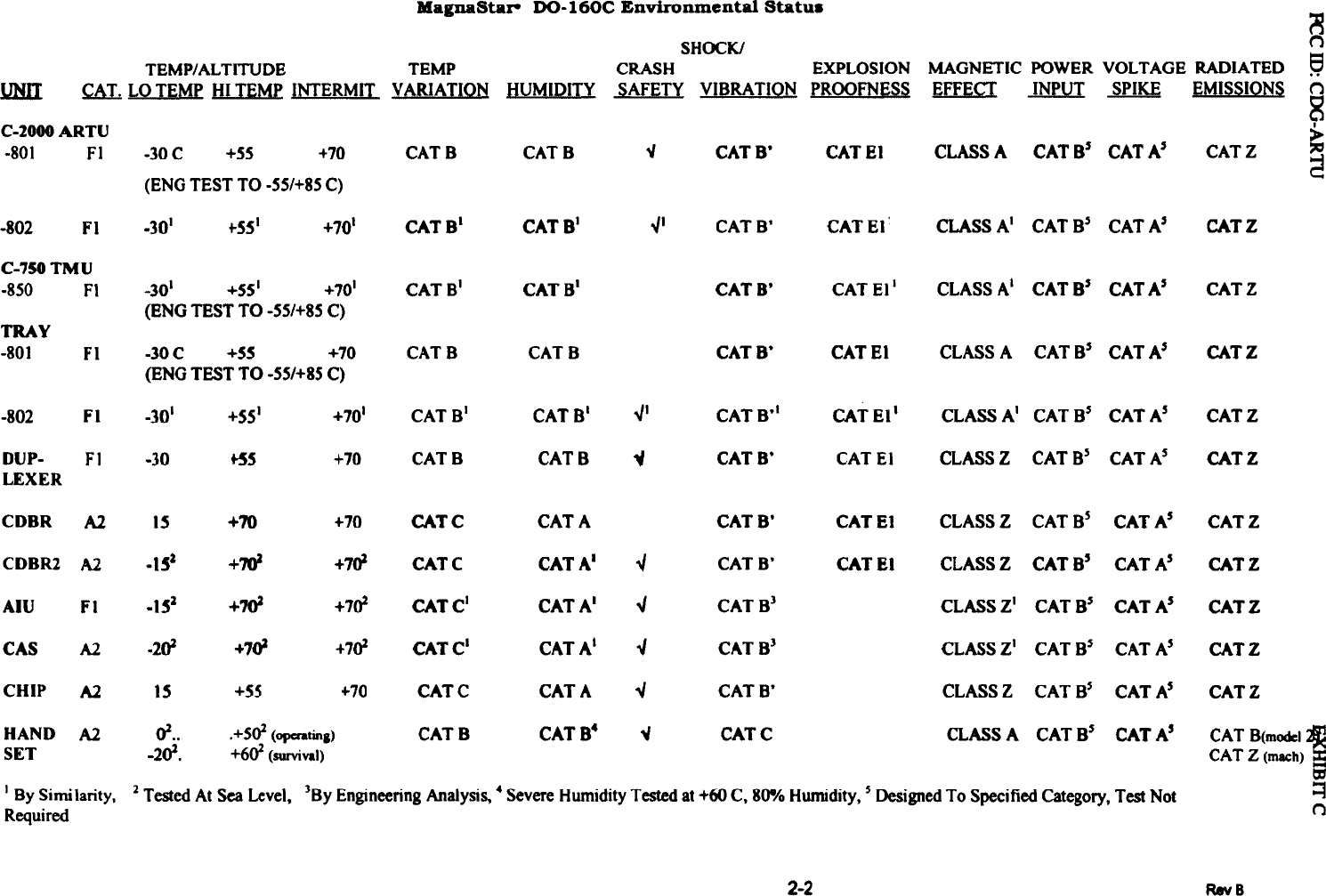
installation manual part one
2.
installation manual part two
3.
installation manual part three
4.
installation manual part four
5.
installation manual part five
6.
installation manual part six
7.
installation manual part seven
installation manual part one
Navigation menu
Upload a User Manual
Namespaces
Wiki Guide
HTML
PDF
Info
Views
User Manual
Discussion / Help
Navigation