Raytheon IIS ARTU Air-Ground Radio System User Manual installation manual part four
Raytheon Company Air-Ground Radio System installation manual part four
UserManual.wiki
>
Raytheon IIS
>
ARTU User Manual
>
installation manual part four
Contents
1.
installation manual part one
2.
installation manual part two
3.
installation manual part three
4.
installation manual part four
5.
installation manual part five
6.
installation manual part six
7.
installation manual part seven
installation manual part four
Navigation menu
Upload a User Manual
Namespaces
Wiki Guide
HTML
PDF
Info
Views
User Manual
Discussion / Help
Navigation
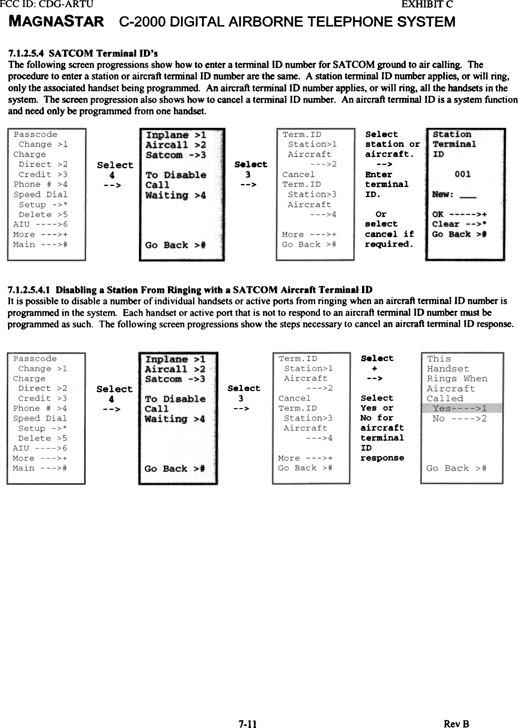
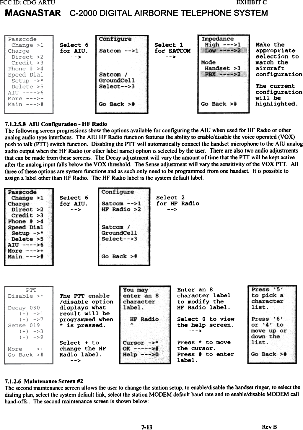
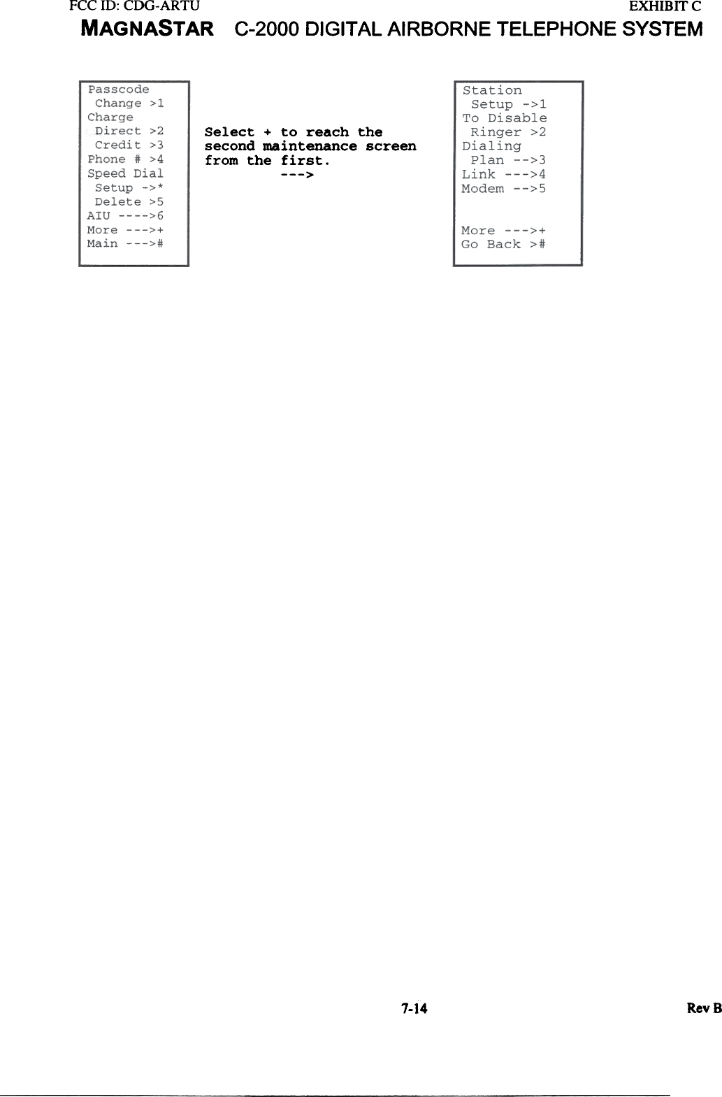
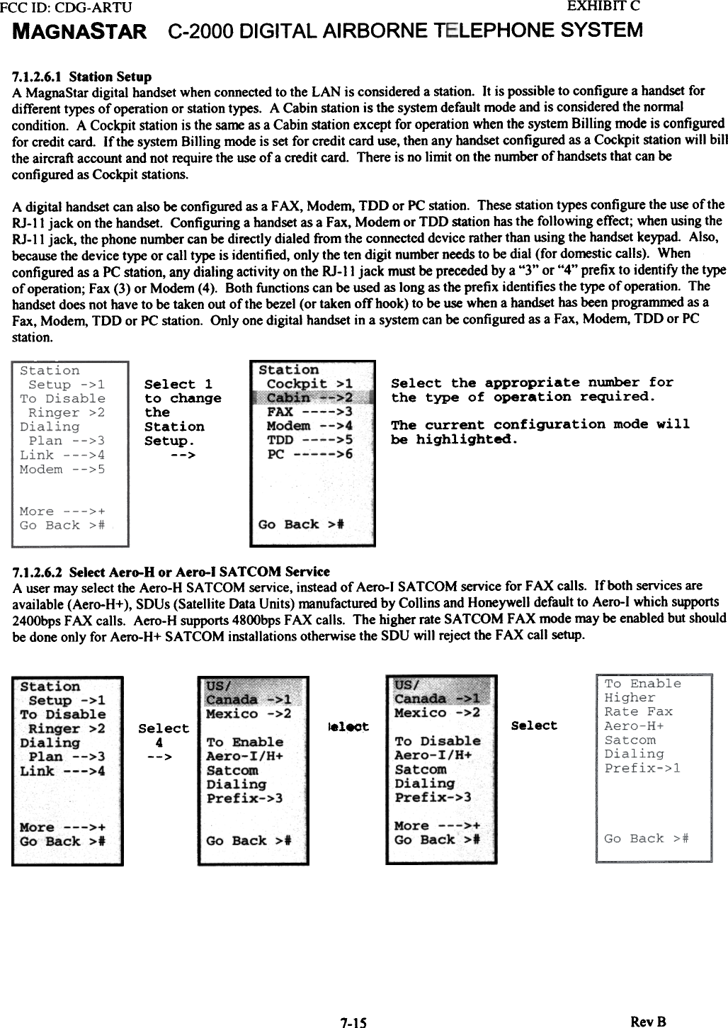
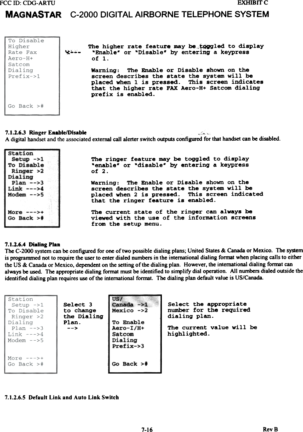
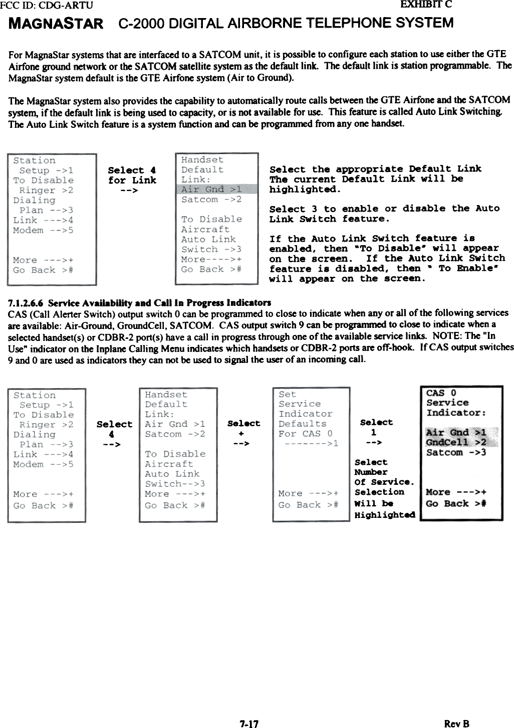
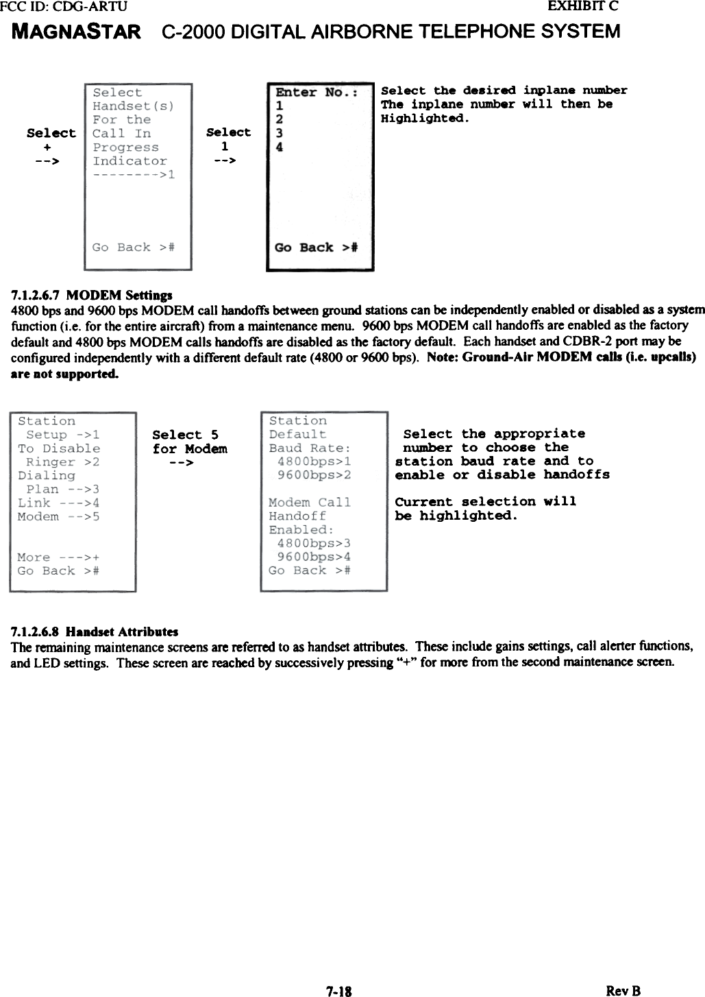
![EXHIBITCC-2000 DIGITAL AIRBORNE TELEPHONE SYSTEMFCC ill: CDG-ARTUMAGNASTAR7.1.2.5.5 CaD WaitingThe following screen progressions show bow to enable or disable the call waiting feature. Call waiting will alert the user ofan additional incoming call regardless of its origin (inplane or ground initiated) while engaged in a telephone call.Inplane>1Aircall >2Satcom ->3 The call Waiting feature may be toggled todisplay enable or disabled by entering akeypress of 4.Select4--> Warning: The Enable or Disable shown on thescreen describe$ the $tate the system will beplaced when a 4 is pressed. The examplescreen indicates that call waiting isdisabled.To EnableCallWaiting >4Go Back >#7.1.2.5.6 Speed DialThe following screen progressions show how to enter speed dial numbers. The following items are to be entered. The threedigit speed dial number (*510 through *549), a phone number and a 10 character label. The label is an optional entry.--EnterdialingsequenceEnterthe typeof service(1= voice,3= Fax,4= Modem)followedby thenumber tobe dialed.Then enter+ for OK.-->Sel-*Spe-DiaSetEnter 3digitspeed dialnumber510-549Enter the threedigit speed dialnumber in the510-549 range.Then enter + forOK.-->Svc+Number1+8882467827 510OK >+Clear -->.Main --->IOK >+Clear -->*Go Back >tSelect5 todeleteanumberYou maY--enter a 10characterlabel.Youent'chalabSelect +to savethe speeddial entryEnter a 10character labelfor the enteredspeed dialnumber. Star Line "CUrsor ->*OK/Next >+OK/Main >tHelp --->0CUrsor ->*OK/Next >+OK/Main >1Help --->0Select 0 toview the helpscreen -->7.1.2.5.7 AIU Configuration - SATCOMThe fo)]owjng screen progressions show the options available for configuring the AlU when used wjth an analog SATCOMsystem. The AlU SA TCOM features include two different impedance configurations and two possible interface modes ofoperation. The two different impedance configurations are High Impedance (WH-IO type) and Low impedance (600 ohm).The two different modes of operation are Handset and PBX. The Handset mode provides no feedback to the user on the LCDdisplay and operates strictly as a handset would. In the PBX mode the handset provides the user with feedback informationon the handset LCD display providing the dialed number and ca)] progress information. This mode is only valid for thoseSA TCOM systems which support handset PBX functions.RevS7-12ectfored1-up>mayer a 10racterel.](https://usermanual.wiki/Raytheon-IIS/ARTU.installation-manual-part-four/User-Guide-257062-Page-2.png)