Raytheon IIS ARTU Air-Ground Radio System User Manual installation manual part six
Raytheon Company Air-Ground Radio System installation manual part six
UserManual.wiki
>
Raytheon IIS
>
ARTU User Manual
>
installation manual part six
Contents
1.
installation manual part one
2.
installation manual part two
3.
installation manual part three
4.
installation manual part four
5.
installation manual part five
6.
installation manual part six
7.
installation manual part seven
installation manual part six
Navigation menu
Upload a User Manual
Namespaces
Wiki Guide
HTML
PDF
Info
Views
User Manual
Discussion / Help
Navigation
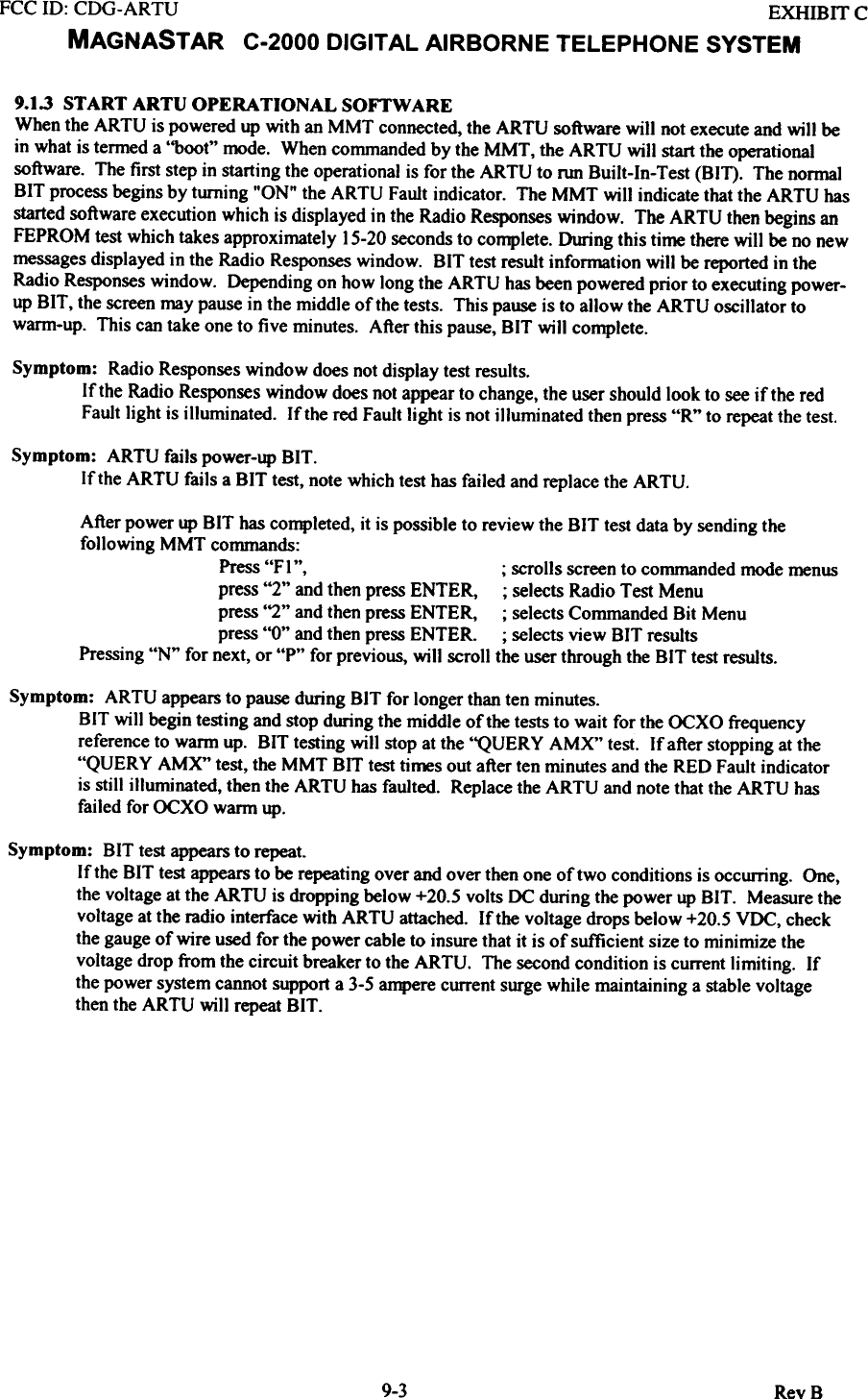
![FCC 10: CDG-ARTU EXHIBIT CMAGNAST AR C-2000 DIGITAL AIRBORNE TELEPHONE SYSTEM9.1.4 LOCKED OFF-LINE STATEFor the MMT to command certain tests for the installation checkout, the ARTU software must be placed ina mode which will allow the ARTU the flexibility to perform these tests. This mode of operation is calledthe "Locked OFF-Line State". This test step is a mode change only. Failure of this mode change will onlyoccur iftbe MMT is not communicating with the ARTU.It should be noted that while the ARTU is in this mode, the Handset screen may go blank and will notrespond to keypad inputs.Symptom: ERROR=> MMT communications failure - timed out.If this message is displaycd in thc Radio Responses window then check the cabling between thcARTU and the MMT. If the cabling is correct then press "R" to repeat the test.V4.0A MMT Radio Re~Radio 8oftw8re executing in locked offline state.+ + VlA ~ Tutorial':DlS1A1O6,,: Syq>toa: ERROR-> I8rr c~icati0D8 failure - tiJ: a) Check the I8rr cable connecti_.: b) Press .R. for repeat.Figure 9.].4. Locked Off-Line State MMT] Troubleshoot Screen.9-5 RevB](https://usermanual.wiki/Raytheon-IIS/ARTU.installation-manual-part-six/User-Guide-257064-Page-9.png)
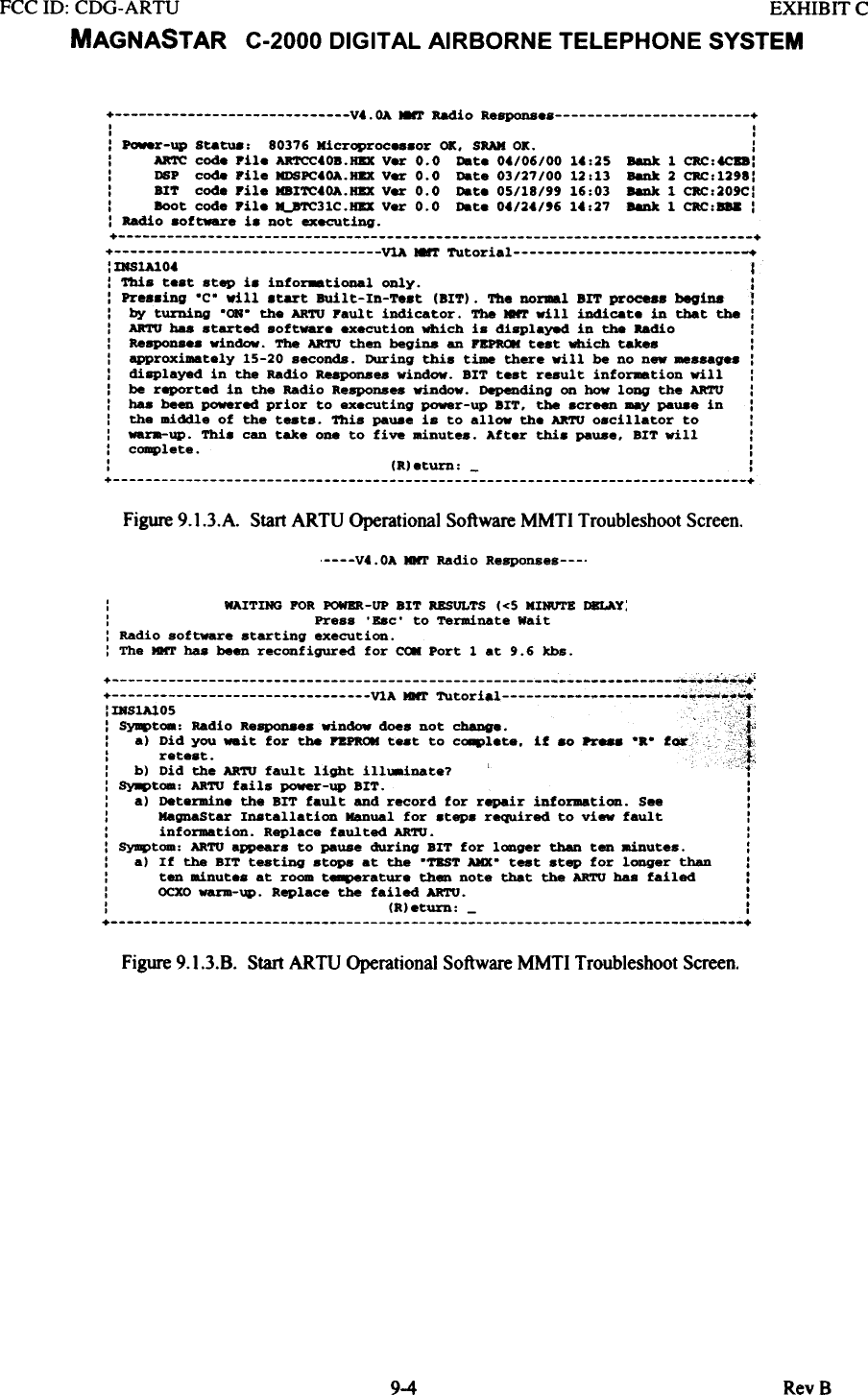
![FCC 10: CDG-ARTU EXHIBIT CMAGNASTAR C-2000 DIGITAL AIRBORNE TELEPHONE SYSTEM9.1.5 ARTU MOUNTING TRAY FAN TESTUnder normal operational conditions, the ARTU Mounting Tray Fan is activated by a switch in the ARTUwhich is under software control. The ARTU monitors a temperature sensor located in the ARTU and isprogrammed to turn on the Fan when the temperature is at approximately room temperature. The ARTUMounting Tray Fan test will command the ARTU to turn the fan "ON" to check operation.Symptom: The ARTU Mounting Tray Fan is not operational.If the ARTU Mounting Tray Fan is not operational, the problem can be caused by the ARTU,wiring to the ARTU Mounting Tray or the Mounting Tray Fan itself. Several steps wi)] berequired to detennine the cause of failure. These steps may also vary depending on whichassembly of the ARTU mounting Tray assembly that is used in the aircraft.For -801 Tra~: Remove power from system Remove the power connector from ARTU J2connector interface and ground pin P I-F of the ARTU Power cable. Apply power to the system.If the fan operates, perform a continuity check on the ARTU Tray - ARTU Power cable interface.If the wiring is correct, replace the ARTU. If the fan does not operate, replace the ARTUMounting Tray.For -802 Trax: Remove the PI connector from the ARTU Mounting Tray. With power removed,grotmd pin Jl-9 on the ARTU Tray. Apply power to the system. If the fan does not operate,replace the ARTU Mounting Tray. If the fan operates, perform a continuity check on the 802ARTU Tray - ARTU Power cable. If the wiring is correct, replace the ARTU. Ifnot replacecable.V4.0A 8'l' Radio Response.C-2000 report8 engineering teat FAN CONTROL performed+ ++ VlA MNT Tutorial +:IRS1A101 :: SYJI4>tca: Pen do.. DOt operate. :: por -801 Tray: ~e power from syst_. R~ J2 connector fr.. ARTU end :: ground pin Pl-P of the ARTU Power cable. Apply ~r to the ayst_. If :: the fen operate8. replace the ARTU. If the fan does not operate. replace:: the ARTU Mounting Tray. :: For -802 Tray: a..ove the Pl connector from the ARTU Mounting Tray. with :: power r~ed. gr~ pin Jl-' on the ARTU Tray. Apply power to the :: syst_. If the fen ~ DOt operate. replace the ARTU Mounting Tray. If :: the fan operatH. perfora . continuity on the 802 ARTU Tray - ARTU :: Power cable. If the continuity is correct. replace the ARTU. If not :: replace cable. :~Figure 9.1.5. ARTU Mounting Tray Fan MMTI Troubleshoot Scret9-6 RevB](https://usermanual.wiki/Raytheon-IIS/ARTU.installation-manual-part-six/User-Guide-257064-Page-10.png)