Raytheon IIS ARTU Air-Ground Radio System User Manual installation manual part six
Raytheon Company Air-Ground Radio System installation manual part six
Contents
installation manual part six
EXHIBfi' C
C-2000 DIGITAL AIRBORNE TELEPHONE SYSTEM
FCC ID: CDG-ARTU
MAGNASTAR
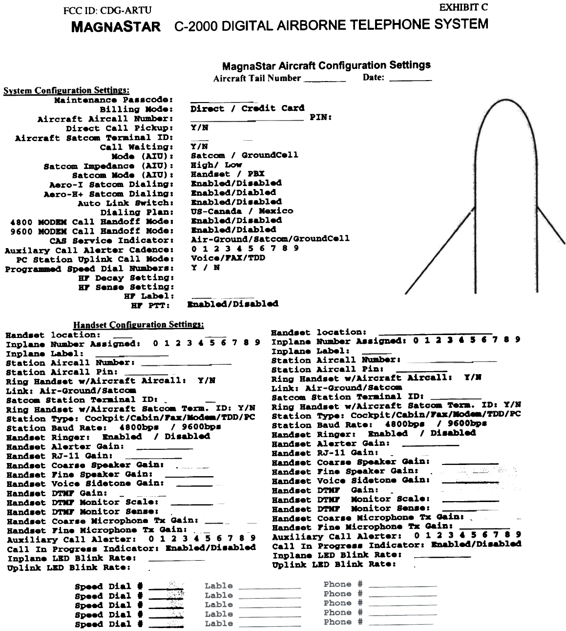
MagnaStar Aircraft Configuration Settings
Aircraft Tail Number Date:
Svstem Confil!uration Settinl!s:
Maintenance Pa88code:
Billing Node:
Aircraft Aircall NUmber:
Direct Call pickup:
Aircraft Satcom Terminal ID:
Call waiting:
Node (AItJ):
Satcom ~edance (AItJ):
Satcom Node (ArO):
Aero-I Satcom Dialing:
Aero-B+ Satcom Dialing:
Auto Link Switchz
Dialing Plan:
'800 MOD" Call Randoff Mode:
9600 MODBM Call Bandoff Mode:
CAS Service Indicator:
Auxilary Call Alerter Cadence:
PC Station uplink Call Mode:
Programm8d Speed Dial Humber8 z
HI' Decay Settingz
HI' Sen.e Setting:
HP Label:
HP P'1'T:
Direct I Credit Card PIN:
Y/R
-
Y/N
Satc~ I GroundCell
Bighl Low
Band.et I PBX
Bnabled/Di8ahled
Bnabled/Diabled
Bnab1ed/Di8ahled
US-Canada I Mexico
BDabled/Di8ab1ed
BDabled/Diabled
Air-Ground/Satc~/QrouDdCe11
0113456789
Voice/FAX/TDD
Y I N
-
8Dabled/ Di .&bled
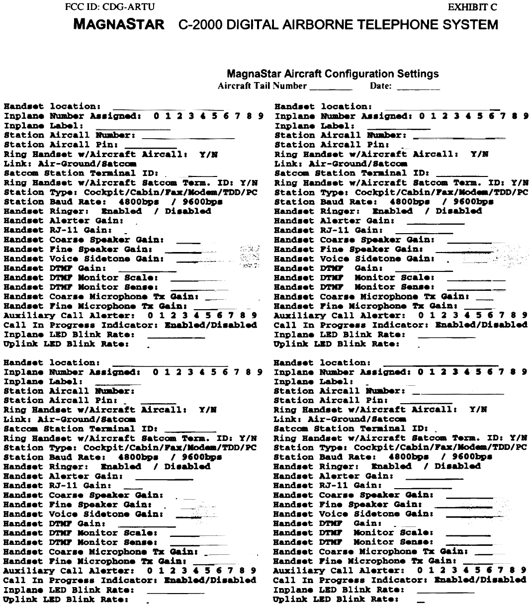
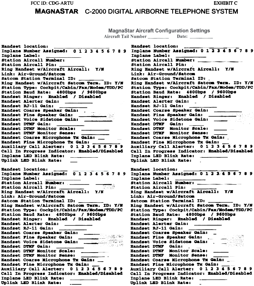
Handset Confi2uration Settin2s:
Hand..t location: - -
Inplane Number Assigned a 0 1 2 3 4 5 6 7 8 9
Inplane Label: -
Station Aircall Numbera Station Aircall pin:
Ring Handset w/Aircraft Aircalla
Linka Air-Oround/Satc~
Satc~ Station Terainal IDa - --
Ring Handset w/Aircraft Satc~ Term. ID: TIN
Station Type: Cockpit/Cabin/Pax/Mod../TDD/PC
Station Baud Rate: 4800bp. I 9600bp.
Hand.et Ringera BDabl84 I Di.abl84
Hand..t Alerter Gain:
Hand..t RJ-ll Gaina
Hand..t Coar.. Speaker Gain a ._-
Handset pine Speaker Gaina
Hand..t Voice Sidetone Gaina
Hand..t D'l'KP Oain: - --
Hand..t DTNP IIoni tor Scale a
Hand..t DTNP Moni tor Sen.e a .
Hand..t Coar.. Microphone Tx Gaina ---
Hand..t pine Microphone Tz Gaina --
Auxiliary Call Alerter: 012 3 4 567 8 9
Call In progre.. Indicator a ~l84/Di.abl84
Inplane LBD Blink Ratea
uplink LBO Blink Rate:
Y/R
Hand..t location:
Inplane II'W8b8r A8.igne4a 0 1 2 J 6 5 , 7 8 9
Inplane Label:
Station Aircall II'W8b8ra
Station Aircall pin a Ring Handset -/Aircraft Aircalla T/R
LiDJr.: Air-Ground/ satc~
Satcom Station Ter8dnal %Da
Ring Handset -/Aircraft Satc~ Te~. %Da Y/R
Station Type: Cockpit/Cabin/rax/~eaJTDD/PC
Station Baud Rate: 6800bp. /9600bp.
Hand..t Ringer: BDabled / Di8able4
Hand..t Alert.r Gain:
Hand..t RJ-11 Gaina -
Hand..t Coar.. Speaker Gaina
Hand..t Fine Speaker Gain: . ~~ ~
Band..t voice sid.tone Gaina ,
Hand..t D'rIIJ' Gain: -
Hand..t DTMF Noni tor Scale a
Band..t D'rIIJ' Noni tor Seu.e a
Hand..t Coar.. Microphone '1'X Gaina ,
Hand..t Fine Kicrophone '1'x Gaina
Auxiliary Call Al.rter: 012 3 6 5 , 7 8 9
Call In Progr... Indicator a BDable4/Di8able4
Inplane LBD BliDJr. Rat.a
UpliDJr. LBD BliDJr. Rate:
Speed Diu' " .
i 1 .!C:;i" Speed D a ~~: i~~c
Speed Dial' ::~"
Speed Dial' c',...",,'
Speed Dial' ~
FCC ill: COG-ARTU
MAGNASTAR
EXHIBITC
C-2000 DIGITAL AIRBORNE TELEPHONE SYSTEM
MagnaStar Aircraft Configuration Settings
Aircraft Tail Number Date:
0123~56789
Y/R
-
BaDd.et location: Inplane Humber Aa.igDed: 0 1 2 3 4 5 I 7 8 t
Inplane Label:
Station Aircall Ru8b8r:_-
Station Aircall pin: --
Ring BaDd.et -/Aircraft Aircall: T/R
Link: Air-Ground/ Satcoa
Satcoa Station Ter8inal ID:
Ring Handset _/Aircraft Satcom T8%m. ID: T/R
Station TYPe: Cockpi t/Cabin/Pax/MOd../TDD/PC
Station Baud Rate: 4800bp. / 'IOObp.
BaDd.et Ringer: BDabled / Di.abled
Hand.et Alerter Gain:
Hand.et RJ-ll Gain:
Hand.et Coar.e Speaker Gain:
Hand.et Fine Speaker Gain: ; .'
Hand.et voice Sidetone Gain: . ~_.,
Handset DTIIP Gain:
Hand.et DTIIP Honi tor Scale:
Hand.et DTIIP Honi tor Senae:
Hand.et Coar.e Microphone Tx Gain: ---
Hand.et pine Kicrophone Tx Gain: --
Auxiliary Call Alerter: 0 1 2 3 4 5 I 7 8 ,
Call In progre.. Indicator: BDabled/Di.abled
Inplane LBD Blink Rate:
Uplink LED Blink Rate:
Band..t location:
Inplan. IfUmb8r A8.igneda
Inplan. Labela ~
Station Aircall Rumb8r:
Station Aircall pina
Ring Band.et -/Aircraft Aircalla
Link: Air-QrouDdISatc~
Sat com Station T.rminal ID: -
Ring Bands.t -/Aircraft Satcom T.rm. ID: TIN
Station TYPe: Cockpit/Cabin/Fax/Mod../TDD/PC
Station Baud Rate: t800bp. I '600bp.
Band..t Ring.r: Bnabled I Di.abled
Band..t Alert.r Gain:
Band..t RJ-ll Gain: -
Band..t Coar.. Speak.r Gain: Band..t Fin. Speak.r Gain a ::,.;~-;;-
Band..t Voice Sid.tone Gaina ~
Band..t DTIIF Gain: ",-,. :;.,
Band..t D'l'KF ~ni tor Scal. a
Band..t DTIIF ~ni tor Sen..a
Bands.t Coar.. Microphone Tx GaiDa ---
Bands.t FiD. Microphone Tx GaiDa Auxiliary Call Al.rt..r: 0 1 2 3 t 5 , 7 8 9
Call In progr.ss Indicatora BDabled/Di.abled
Inplan. LBD Blink Rate:
Uplink LED Blink Rat.: -
--
0123'5678.9 Band..t location:
Inplan. NUmber Aa.ignedl 0 ~ 2 J '5 , 7 . 9
Inplane Label: -
Station Aircall -.her: -
Station Aircall pilla
Ring Hand..t -/Aircraft Aircalll Y/R
Link: Air-Qround/Satc~
Satcom Station Ter8dnal ID: -
Ring Band..t _/Aircraft Satcoa T.:m. ID: Y/R
Station Typ.1 Cockpit/Cabin/Fax/Modem/TDD/PC
Station Baud Rat.1 4.00bp. / 9600bp.
BaDd..t Ring.r: Bnabled / Di.abled
Band..t Al.rt.r Gain I
Hand..t RJ-ll Gainl
Hand..t Coar.. Speaker Gainl
Hand..t Fin. Speak.r Gain I ;i
Band..t Voice Sid.tone Gainl ..,
Band..t I)'1'Np Gain: -
Hand..t ~ ~nitor Scal.1
Hand..t DTKr Moni tor S.n..1
Band..t Coar.. Microphon. TX Gainl
BaDd..t pin. Microphone TX Gainl
Auxiliary Call Al.rt.r: 0 ~ 2 3 4 5 6 7 . 9
Call In progr... Indicator I Bnabled/Di.abled
Inplan. LBD Blink Rat.1
Uplink LED Blink Rat.: -
Hand.et location: -
Inplane B\uaber Aa.igned I
Inplane Labell
Station Aircall RU8b8r:
Station Aircall Pinl -
Ring Hand.et -/Aircraft Aircalll T/B
Linkl Air-around/8at~
Satc08 Station Ter8dnal ZDI
Ring Hand.et -/Aircraft Satcam T8~. ID: TIN
Station Type: Cockpit/Cabin/Pax/Nodea/TDD/PC
Station Baud Ratel tBOObp. / ,'OObp.
Hand.et Ringer: BDabled I Di.abled
Hand.et Alerter aain I
Hand.et RJ-ll Gain: -
Hand.et Coar.e Speaker Gain: .
Hand.et Fine Speaker (Jainl 2C~
~
Hand.et voice Sidetone Gain: --
Hand.et DTIII' aain:
Hand.et DTIII' Monitor Scalel
Hand.et DTIII' Moni tor Sen.el
Hand.et Coar.e Microphone TX Gain I ~
Hand.et Fine Microphone TX GaiDI Auxiliary Call Alerter: 0 1 2 3 , 5 , 7 B ,
Call In Progre.. Indicator: BDabled/Di.abled
Inplane LED Blink Rate:
Uplink LED Blink Rate: -
FCC ID: CDG-ARTU
MAGNASTAR
EXHlBlTC
C-2000 DIGITAL AI RBORNE TELEPHONE SYSTEM
0123456789
Band.et location: -
Inplane Rumber Aa.ignedl
Inplane Labell - -
Station Aircall R\l8ber1
Station Aircall pins
Ring Band.et -/Aircraft Aircalll T/R
Link I Air-GrouDd/Satc~
Satcom Station Terminal ID:
Ring Band.et -/Aircraft Satcom Te~. ID: T/R
Station Type: Cockpit/Cabin/Fax/Nodea/TDD/PC
Station Baud Ratel j800bp. l'fOObp.
Band..t Ring.r: 8Dabled I Diaabled
Band..t Al.rt.r Gain:
Band..t RJ-ll Gain I
Band..t Coar.. Speak.r ~iD 1 -
Band..t Fine Speak.r ~inl ~,,: ,
Band..t Voice sid.tone ~iDl I'~
Band..t D'1'IIF ~in:
Band..t DTKF Monitor Scal.:
Band..t D'1'IIF Moni tor Sen..1
BaDd..t Coar.. Microphone TX ~inl --
Band..t Fine Microphon. Tx ~inl
Auxiliary Call Al.rter: 0 1 2 3 j 5 f 7 8 ,
Call In progr... Indicator: 8Dabled/Di.abled
Inplane LBD Blink Ratel
Uplink LED Blink Rat.: -
BaD4..t location: - -
Inplane Number A8.ignedl 0 1 2 3 6 5 6 7 8 9
Inplane Labell
Station Aircall RU8b8r1
Station Aircall pin: .
Ring BaD4..t w/Aircraft Aircalll Y/R
Link: Air-GroUDd/Satc~
Satcom Station T.rBdnal ID: -
Ring Band..t w/Aircraft Satc08 T8~. ID: Y I.
Station Type: Cockpit/Cabin/rax/Modea/TDD/PC
Station Baud Ratel 4800bp. 19600bp.
BaD4..t Ring.r I 8Dabled 1 Di.abled
Band..t Alert.r Gainl -
BaDd.et RJ-ll Gainl
BaD4..t Coar.. Speaker Qainl
Band..t riDe Speak.r Qain: 10.';'
Band.et Voice Sid.ton. Qainl ~--
Band.et D'1'IIF Gain I
Band..t D'1'IIF Monitor Scal.1 -
Band.et DTKr Monitor S8D8.1
BaD4..t Coar.. Microphone TX Gainl --
Band..t riDe Microphon. TX Gainl Auxiliary Call Al.rterl 0 1 2 3 6 5 6 7 8 9
Call In Progr... Indicator: BDabled/Di.abled
Inplan8 LSD Blink Rate I -
Uplink LSD Blink Rat.:
0123456789
y,.
Band.et location: - -
Inplane NwDber Aa.igD,ed1 0 1 2 J, & 5 I' 7 8 9
Inplane Labell
Station Aircall .u.berl -
Station Aircall Pinl
Ring Band.et w/Aircra~t Aircalll T/R
Linkl Air-GroW1d/Satc~
Satcom Station TermiDal IDI
Ring BaD4.et w/Aircraft Satc~~. ID: TIS
Station TYPe: Cockpit/Cabin/raz/~~~/TDD/PC
Station Baud Ratel 4800bp. 191'OObp.
Band.et Ringer: BDable4 I Di.able4
Band.et Alerter Gain:
Band.et RJ-ll Gainl
Band.et Coar.e Speaker Gain I -
Band.et Pine Speaker Gainl -- --"
Band.et voice sidetone Gainl -
Band.et D'1'KF Gain I -
Band.et DTMF Monitor Scale I
BaD4.et DTHF Moni tor Sen.el
Band.et Coar.e Kicropbone TZ Gainl ---
Band.et pine Micropbone TZ Gainl ---
Auxiliary Call Alerterl 0 1 2 3 4 5 I' 7 8 9
Call In Progre.. Indicator: BDable4/Di.abled
Inplane LSD Blink Ratel -
Uplink LSD Blink Rate: -
Band..t location:
Inplane Number A..igne4a
Inplane Labela ~-
Station Aircall RU8b8ra . -"
Station Aircall pina 'cot'
Ring BaDc!.et -/Aircraft Aircalla -"
Link a Ai r-Ground I Satc~
Satcom Station TerBdnal ID:
Ring BaDc!..t -/Aircraft Satc~ T.Em. XD: Y/S
Station Type: Cockpi t/Cabin/Paz/Mod../TDD/PC
Station Baud Rat.a j800bp. I'SOObp.
BaDc!..t Ring.r: BDablec! I Di.ablec!
BaDd..t Al.rt.r Gain:
Ban4..t RJ-ll Gain a
BaDc!..t Coar.. Speaker Gaina
BaD4..t pine Speak.r Gaina ."~'j.-~c
Ban4..t Voice Sid.ton. Gaina - :":';;;:ii
BaDd..t D'1'IIF Gain: '0' ,"'C:
Band..t D'1'IIF Koni tor Scale:
BaDd..t DTKF Koni tor Sen..: -
Band..t Coar.. Microphone '1'z GaiDa -
BaDd..t Pine Microphon. '1'z Gaina ---
Auxiliary Call Al.rtera 0 1 2 3 . 5 S 7 8 ,
Call Xn Progr... Indicator: 8Dablec!/Di.ablec!
Inplane LED Blink Rate:
uplink ~D Blink Rat.a
EXHIBrrc
C-2000 DIGITAL AIRBORNE TELEPHONE SYSTEM
FCC ID: CDG-ARTU
MAGNASTAR
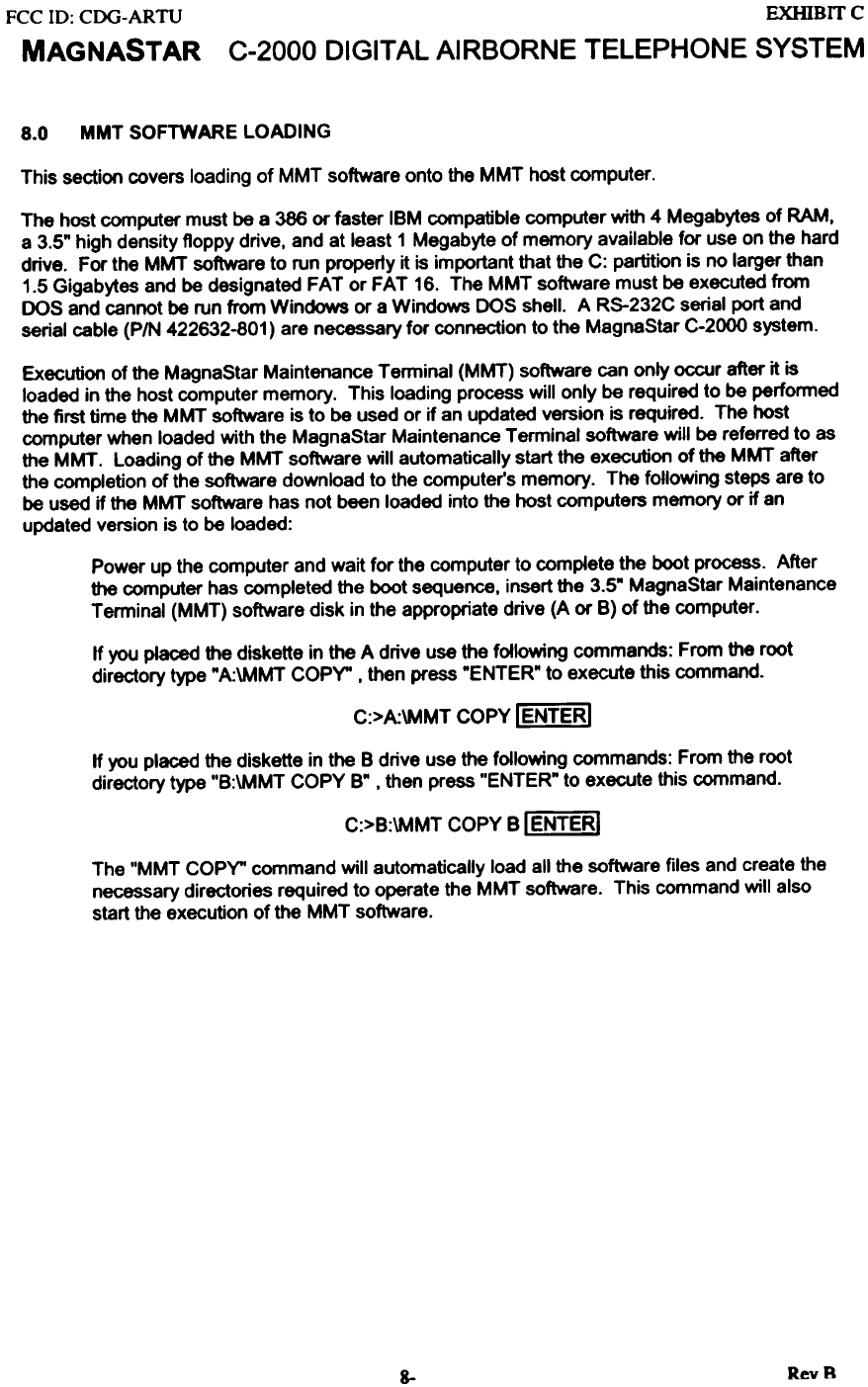
MMT SOFTWARE LOADING
8.0
This section covers loading of MMT software onto the MMT host computer.
The host computer must be a 386 or faster IBM compatible computer with 4 Megabytes of RAM.
a 3.5" high density floppy drive. and at least 1 Megabyte of memory available for use on the hard
drive. For the MMT software to run property it is important that the C: partition is no larger than
1.5 Gigabytes and be designated FAT or FAT 16. The MMT software must be executed from
DOS and cannot be run from Windows or a Windows DOS shell. A RS-232C serial port and
serial cable (PIN 422632-801) are necessary for connection to the MagnaStar C-2000 system.
Execution of the MagnaStar Maintenance Terminal (MMT) software can only occur after it is
loaded in the host computer memory. This loading process will only be required to be performed
the first time the MMT software is to be used or if an updated version is required. The host
computer when loaded with the MagnaStar Maintenance Terminal software will be referred to as
the MMT. Loading of the MMT software will automatically start the execution of the MMT after
the completion of the software download to the computer's memory. The following steps are to
be used if the MMT software has not been loaded into the host computers memory or if an
updated version is to be loaded:
Power up the computer and wait for the computer to complete the boot process. After
the computer has completed the boot sequence, insert the 3.5- MagnaStar Maintenance
Terminal (MMT) software disk in the appropriate drive (A or B) of the computer.
If you placed the diskette in the A drive use the following commands: From the root
directory type "A:\MMT COPY" . then press "ENTER" to execute this command.
C:>A:\MMT COpy IENTERI
If you placed the diskette in the B drive use the following commands: From the root
directory type "B:\MMT COpy B" , then press "ENTER" to execute this command.
C:>B:\MMT COpy B I ENTERI
The "MMT COPY" command will automatically load all the software files and create the
necessary directories required to operate the MMT software. This command will also
start the execution of the MMT software.
RevB
8-
FCC ID: CDG-ARTU EXHIBIT C
MAGNASTAR C-2000 DIGITAL AIRBORNE TELEPHONE SYSTEM
EQUIPMENT TROUBLESHOOTING PROCEDURES
...9-1
...9-1
...9-1
9-2
...9-3
...9-5
...9-6
...9-7
...9-9
.9-11
.9-12
.9-13
.9-14
.9-15
.9-16
.9-16
.9-17
.9-17
.9-18
.9-18
.9-20
.9-22
.9-23
.9-26
.9-27
9-27
9-29
.9-30
9-30
9-32
9.0 EQUIPMENT TROUBLESHOOTING PROCEDURES ,..
9.1 TROUBLESHOOTING PROCEDURE FOR MMT INST ALLA TION TUTORIAL
9.1.1 C-2000 SYSTEM POWER UP 9.1.2 MMT COMMUNICATION VERIFICATION 9.1.3 START ARTU OPERATIONAL SOFTWARE 9.1.4 LOCKED OFF-LINE STATE 9.1.5 ARTU MOUNTING TRAY FAN TEST 9.1.6 ARTU TRANSMI1TER OUTPUT POWER 9.1.7 ARTU RECEIVE SIGNAL STRENGTH MEASUREMENT 9.1.8 HANDSET / LAN TEST """""""".'.."""""""'"
9.1.9 RESET MAINTENANCE ACCESS PASSCODE 9.1.10 UNLOCKED ONLINE STATE 9.1.11 RSS MEASUREMENT USING GENSTARGROUND STATION 9.1.12 MMTI TROUBLESHOOT CONCLUSION 9.1 Additioul MMTI Troubleshoot Informatio. 9.2.1 Data Cable Pull Check .""' """"'.".""'.' """"""'" 9.2.2 Fault Counter Check 9.2.3 Flight Test Log 9.2.4 L-Band Interference Tests 9.2.5 CEPT -EI Communication Verification 9.3 MMTI Commanded Mode "" """""""""."""..""
9.3.1 MMTI Commanded Mode - C-2000 MMT Boot Menu 9.3.2 MMTI Commanded Mode - C-2(xx) MMT Radio Configuration Menu 9.3.3 MMTI Commanded Mode - C-2(xx) MMT Radio Installation/Test Menu 9.3.3.1 C-2000 MMT Commanded BIT Menu 9.3.3.2 C-2(xx) MMT RF Test Menu """ '."..".'."' ' ""' "".." 9.3.3.3 C-2(xx) MMT Handset Test Menu 9.3.3.4 C-2(xx) MMT Radio Maintenance Operations Menu 9.3.3.4.1 C-2000 MMT Debug Menu. , 9.4 HaDdIet Text Meuages
RevS
9-i
FCC ID: CDG-ARTU EXHIBIT C
MAGNAST AR C-2000 DIGITAL AIRBORNE TELEPHONE SYSTEM
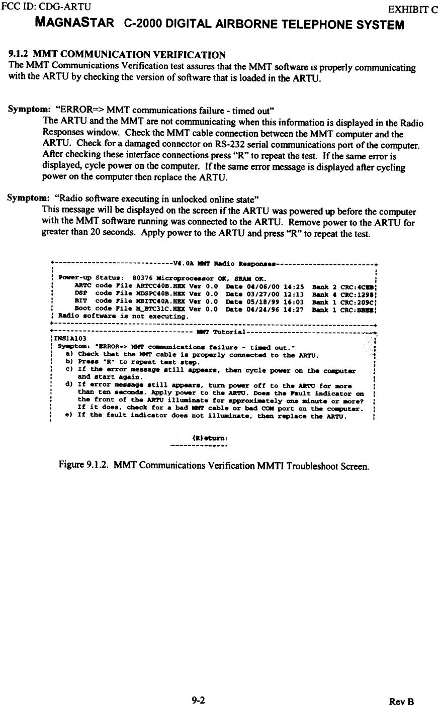
9.1.2 MMT COMMUNICATION VERIFICATION
The MMT Communications Verification test assures that the MMT software is properly communicating
with the ARTU by checking the version of software that is loaded in the ARTU.
Symptom: "ERROR=> MMT communications failure - timed out"
The ARTU and the MMT are not communicating when this information is displayed in the Radio
Responses window. Check the MMT cable connection between the MMT computer and the
ARTU. Check for a damaged connector on RS-232 serial communications port of the computer.
After checking these interface connections press "R" to repeat the test. If the same error is
displayed. cycle power on the computer. If the same error message is displayed after cycling
power on the computer then replace the ARTU.
Symptom: "Radio software executing in unlocked online state"
This message will be displayed on the screen if the ARTU was powered up before the computer
with the MMT software running was connected to the ARTU. Remove power to the ARTU for
greater than 20 seconds. Apply power to the ARTU and press "R" to repeat the test.
+ V..OA MNT R6dio Re8PQna +
, I
, ,
: Power-up Status: 80376 Kicroproc...or 01, BRAN OK. :
: ARTC code pile ARTCC40B.HBX Ver 0.0 net. 0./06/00 1.:25 Bank 2 CRC:4CB8:
: DBP code Pile MDSPC.OB.HEX Ver 0.0 Dat. 03/27/00 12:13 B8Dk 4 cac:1298:
: BIT code Pile MBITC.OA.HBX Ver 0.0 net. 05/18/99 16:03 Bank 1 CRC:209C:
: Boot code Pile ~31C.HBX Ver 0.0 Date 0./2./96 14:27 B8Dk 1 CRC:B818:
: R6dio software is not executing.
+ +
+ MMT Tutorial ~--~
'DSlA103 .
"
: Sy8ptom: "ERROR-> MNT cO8mUnications failure - ti-.d out." 1
: a) Check that the MNT cable i. properly connected to the AR'I'U. ~
: b) Pr..s "R" to repeat test step. J
: c) If the error -ssage still appears, then cycle power on the coqlUter J
: and start again. :
: d) If error -.sage still appears, turn power off to the AR'I'U for more:
: than ten seconds. Apply ~r to the AR'ro. Does the pault indicator on :
: the front of the AR'I'U illuminate for appr_~tely one .!nut. or 8Ore? :
: If it does, cbeck for a bad MNT cable or bad C(»I port on the c~ter. :
: e) If the fault indicator does not illuminate, tben replace the ARTU. :
,
(a.8tuzn ,
Figure 9.1.2. MMT Communications Verification MMTI Troubleshoot Screen.
9-2 RevB
FCC ID: CDG-ARTU EXHIBIT C
MAGNASTAR C-2000 DIGITAL AIRBORNE TELEPHONE SYSTEM
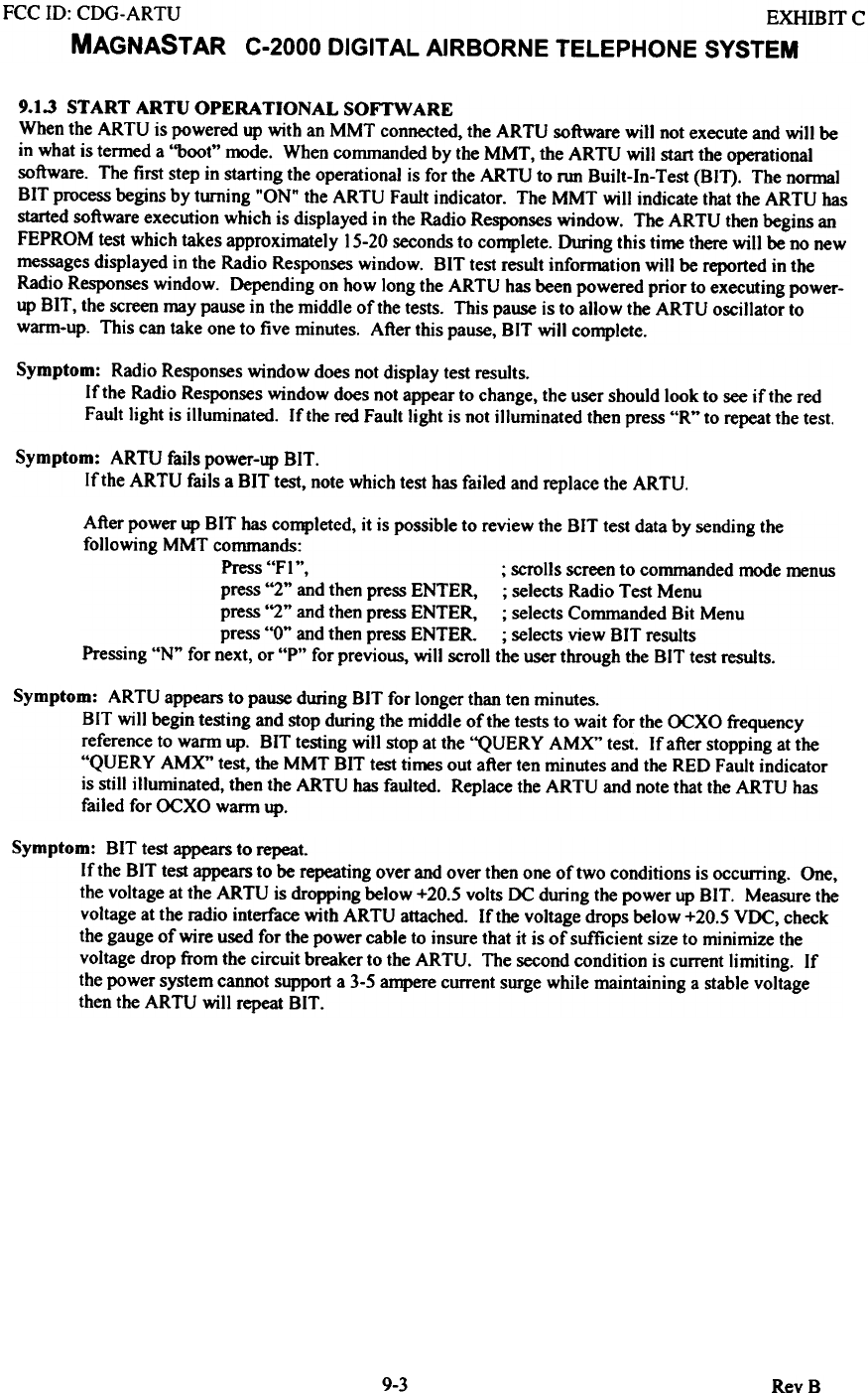
9.1.3 START ARTU OPERATIONAL SOFTWARE
When the ARTU is powered up with an MMT connected, the ARTU software will not execute and will be
in what is termed a "boot" mode. When commanded by the MMT, the ARTU will start the operational
software. The first step in starting the operational is for the ARTU to run Built-In-Test (BIT). The normal
BIT process begins by turning "ON" the ARTU Fault indicator. The MMT will indicate that the ARTU has
started software execution which is displayed in the Radio Responses window. The ARTU then begins an
FEPROM test which takes approximately 15-20 seconds to complete. Owing this time there will be no new
messages displayed in the Radio Responses window. BIT test result information will be reported in the
Radio Responses window. Depending on how long the ARTU has been powered prior to executing power-
up BIT, the screen may pause in the middle of the tests. This pause is to allow the ARTU oscillator to
warm-up. This can take one to five minutes. After this pause, BIT will complete.
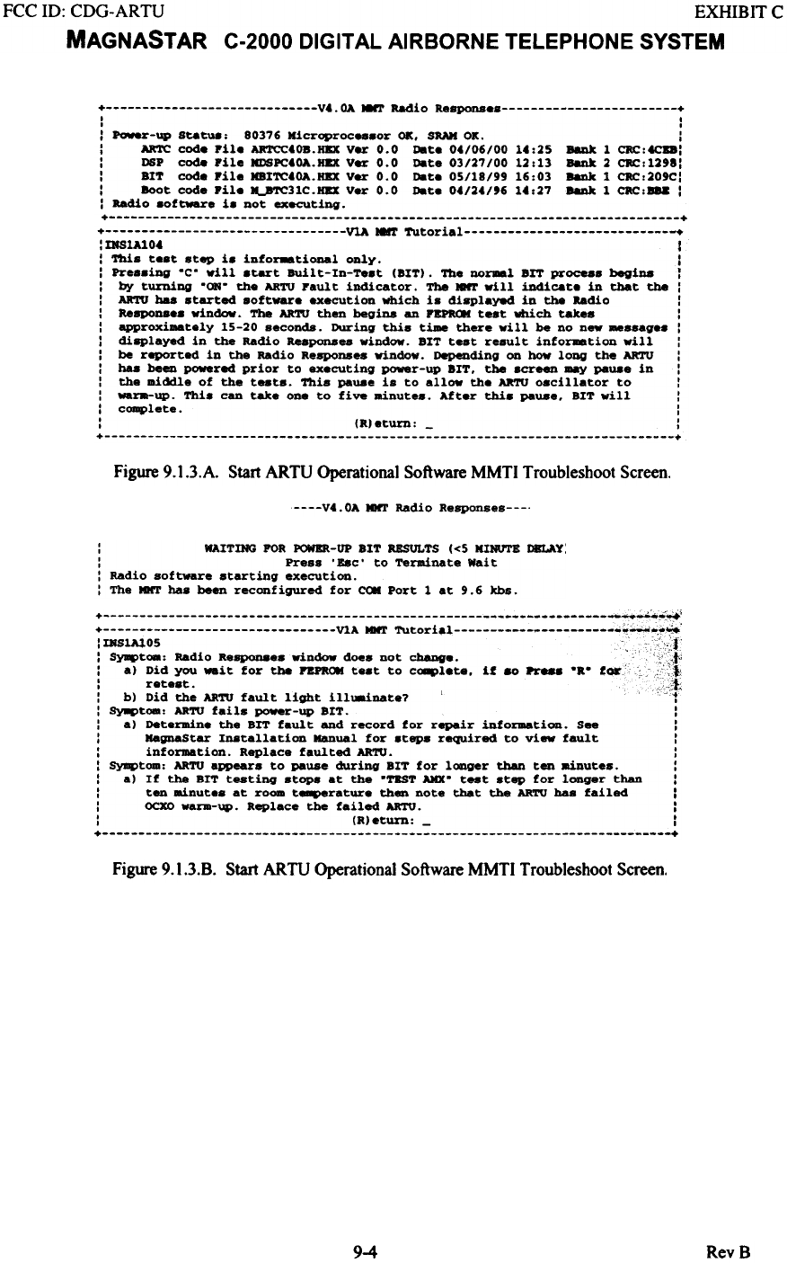
Symptom: Radio Responses window does not display test results.
If the Radio Responses window does not appear to change, the user should look to see if the red
Fault light is illuminated. If the red Fault light is not illuminated then press "R" to repeat the test.
Symptom: ARTU fails power-up BIT.
If the ARTU fails a BIT test, note which test has failed and replace the ARTU.
After power up BIT has completed, it is possible to review the BIT test data by sending the
following MMT commands:
Press "FI ", ; scrolls screen to commanded mode menus
press "2" and then press ENTER, ; selects Radio Test Menu
press "2" and then press ENTER, ; selects Commanded Bit Menu
press "0" and then press ENTER. ; selects view BIT results
Pressing "N" for next, or "P" for previous, will scroll the user through the BIT test results.
Symptom: ARTU appears to pause during BIT for longer than ten minutes.
BIT will begin testing and stop during the middle of the tests to wait for the OCXO frequency
reference to warm up. BIT testing will stop at the "QUERY AMX" test. Ifafter stopping at the
"QUERY AM)(" test, the MMT BIT test times out after ten minutes and the RED Fault indicator
is still illuminated, then the ARTU has faulted. Replace the ARTU and note that the ARTU has
failed for OCXO warm up.
Symptom: BIT test appears to repeat.
If the BIT test appears to be repeating over and over then one of two conditions is occurring. One,
the voltage at the ARTU is dropping below +20.5 volts DC during the power up BIT. Measure the
voltage at the radio interface with ARTU attached. If the voltage drops below +20.5 VDC, check
the gauge of wire used for the power cable to insure that it is of sufficient size to minimize the
voltage drop from the circuit breaker to the ARTU. The second condition is current limiting. If
the power system cannot support a 3-5 ampere current surge while maintaining a stable voltage
then the ARTU will repeat BIT.
9-3 RevB
FCC 10: CDG-ARTU EXHIBIT C
MAGNASTAR C-2000 DIGITAL AIRBORNE TELEPHONE SYSTEM
+ V4. OA NNT Radio Response +
I I
I I
: Power-up Statu8, 80376 Kicroproc...or OK. SRAH ox. :
: ARTC code Pile ARTCC4OB.HIX Ver 0.0 Date 04/06/00 14,25 BaDk 1 CRC,~:
: DSP code Pile KDSPC40A.HIX Ver 0.0 Date 03/27/00 12,13 BaDk 2 CRC,1298:
: BIT code pile MBITC40A.HIX Ver 0.0 Date 05/18/99 16,03 BaDk 1 CRC,209C:
: Boot code Pile ~31C.HBX Ver 0.0 Date 04/24/'6 14,27 BaDk 1 CRC,B8& :
: Radio sottware is not executing.
+ +
+ V1A NNT Tutorial +
: IJfS1A104 1
: This test step is info~tional only. :
: Pressing .C' will start Built-In-Test (BIT). The no~l BIT process begina 1
: by turning .(»t. the ARro pault indicator. The ~ will indicate in that the :
: AR'1'U baa started sott~e execution which is displayed in the Radio :
: Respon... window. The AR'1'U then begins an PBPftCIf test which takes :
: approximately 15-20 seconds. During this time there will be no new ..ssages :
: di8Played in the Radio Responses window. BIT test result into~tion will:
: be reported in the Radio Responses window. Depending on how long the ARTU :
: baa been powered prior to executing power-up BIT. the screen may paU8e in :
: the middle ot the tests. This paU8e is to allow the ARTU 08cillator to :
: _ra-up. This can take one to five IBinutes. After this paU8e. BIT will :
: complete. :
: (R)eturn, - :
+ +
Figure 9.l.3.A. Start ARTU Operational Software MMTI Troubleshoot Screen.
V4. OA MMT Radio Responses
: WAITDfG FOR POWER-UP BIT RESULTS «5 IIIMnE DELAY:
: Press 'B8c' to Terminate Wait
: Radio software starting execution.
: The KIlT baa been reconfigured for CON Port 1 at 9.6 kbs.
'IR S'.'O S c ;' f'
, ,C',
: S~t_: Radio ~SP0D8es window does not change. ';;';;~
: al Did you W8~t for the PZPROM test to cO8plete. if 80 Pr88s "R" for,:,~
: rete.t. "};
: bl Did the ARro fault light illlainate? cf
: Sy8ptoa: ARro fails power-up BIT. :
: al Determine the Brr fault and record for repair information. See :
: KagnaStar Inatallation Manual for steps required to view fault :
: information. Replace faulted ARTU. :
: Symptom: ARro appears to pause during Brr for l~ger than ten ainutes. :
: al If the BIT testing stops at the "TEST AKX" test step for longer than :
: ten ainute. at ro- t~rature then note that the ARTU baa failed :
: OCXO ~-up. Replace the failed ARTU. :
: (Rleturn: - I
+ +
Figure 9.1.3.8. Start ARTU Operational Software MMTI Troubleshoot Screen.
9-4 RevB
FCC 10: CDG-ARTU EXHIBIT C
MAGNAST AR C-2000 DIGITAL AIRBORNE TELEPHONE SYSTEM
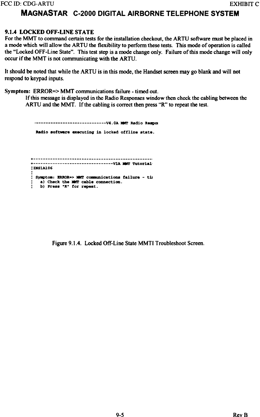
9.1.4 LOCKED OFF-LINE STATE
For the MMT to command certain tests for the installation checkout, the ARTU software must be placed in
a mode which will allow the ARTU the flexibility to perform these tests. This mode of operation is called
the "Locked OFF-Line State". This test step is a mode change only. Failure of this mode change will only
occur iftbe MMT is not communicating with the ARTU.
It should be noted that while the ARTU is in this mode, the Handset screen may go blank and will not
respond to keypad inputs.
Symptom: ERROR=> MMT communications failure - timed out.
If this message is displaycd in thc Radio Responses window then check the cabling between thc
ARTU and the MMT. If the cabling is correct then press "R" to repeat the test.
V4.0A MMT Radio Re~
Radio 8oftw8re executing in locked offline state.
+ + VlA ~ Tutorial'
:DlS1A1O6
,
,
: Syq>toa: ERROR-> I8rr c~icati0D8 failure - tiJ
: a) Check the I8rr cable connecti_.
: b) Press .R. for repeat.
Figure 9.].4. Locked Off-Line State MMT] Troubleshoot Screen.
9-5 RevB
FCC 10: CDG-ARTU EXHIBIT C
MAGNASTAR C-2000 DIGITAL AIRBORNE TELEPHONE SYSTEM
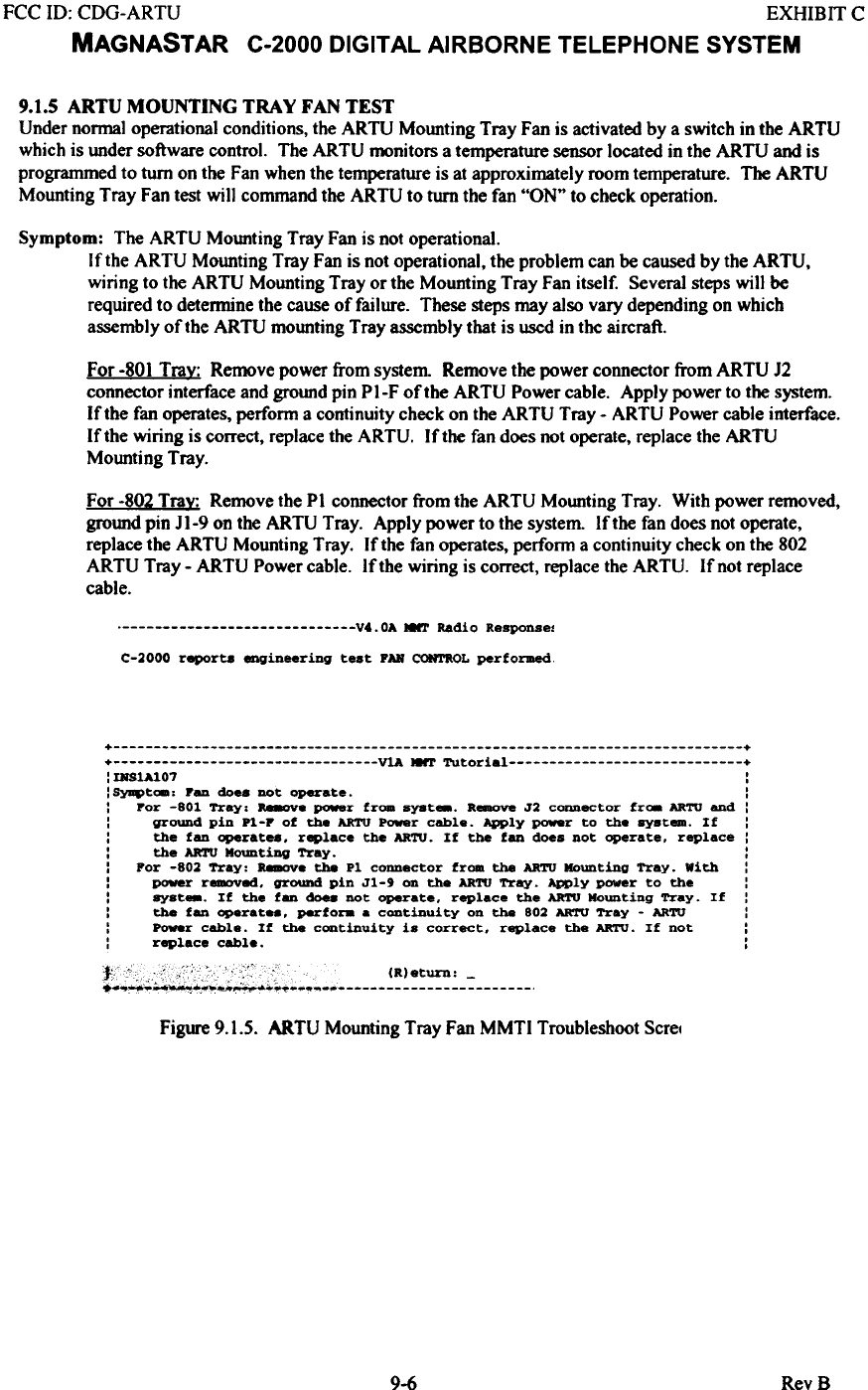
9.1.5 ARTU MOUNTING TRAY FAN TEST
Under normal operational conditions, the ARTU Mounting Tray Fan is activated by a switch in the ARTU
which is under software control. The ARTU monitors a temperature sensor located in the ARTU and is
programmed to turn on the Fan when the temperature is at approximately room temperature. The ARTU
Mounting Tray Fan test will command the ARTU to turn the fan "ON" to check operation.
Symptom: The ARTU Mounting Tray Fan is not operational.
If the ARTU Mounting Tray Fan is not operational, the problem can be caused by the ARTU,
wiring to the ARTU Mounting Tray or the Mounting Tray Fan itself. Several steps wi)] be
required to detennine the cause of failure. These steps may also vary depending on which
assembly of the ARTU mounting Tray assembly that is used in the aircraft.
For -801 Tra~: Remove power from system Remove the power connector from ARTU J2
connector interface and ground pin P I-F of the ARTU Power cable. Apply power to the system.
If the fan operates, perform a continuity check on the ARTU Tray - ARTU Power cable interface.
If the wiring is correct, replace the ARTU. If the fan does not operate, replace the ARTU
Mounting Tray.
For -802 Trax: Remove the PI connector from the ARTU Mounting Tray. With power removed,
grotmd pin Jl-9 on the ARTU Tray. Apply power to the system. If the fan does not operate,
replace the ARTU Mounting Tray. If the fan operates, perform a continuity check on the 802
ARTU Tray - ARTU Power cable. If the wiring is correct, replace the ARTU. Ifnot replace
cable.
V4.0A 8'l' Radio Response.
C-2000 report8 engineering teat FAN CONTROL performed
+ +
+ VlA MNT Tutorial +
:IRS1A101 :
: SYJI4>tca: Pen do.. DOt operate. :
: por -801 Tray: ~e power from syst_. R~ J2 connector fr.. ARTU end :
: ground pin Pl-P of the ARTU Power cable. Apply ~r to the ayst_. If :
: the fen operate8. replace the ARTU. If the fan does not operate. replace:
: the ARTU Mounting Tray. :
: For -802 Tray: a..ove the Pl connector from the ARTU Mounting Tray. with :
: power r~ed. gr~ pin Jl-' on the ARTU Tray. Apply power to the :
: syst_. If the fen ~ DOt operate. replace the ARTU Mounting Tray. If :
: the fan operatH. perfora . continuity on the 802 ARTU Tray - ARTU :
: Power cable. If the continuity is correct. replace the ARTU. If not :
: replace cable. :
~
Figure 9.1.5. ARTU Mounting Tray Fan MMTI Troubleshoot Scret
9-6 RevB
FCC 10: CDG-ARTU EXHIBIT C
MAGNASTAR C-2000 DIGITAL AIRBORNE TELEPHONE SYSTEM
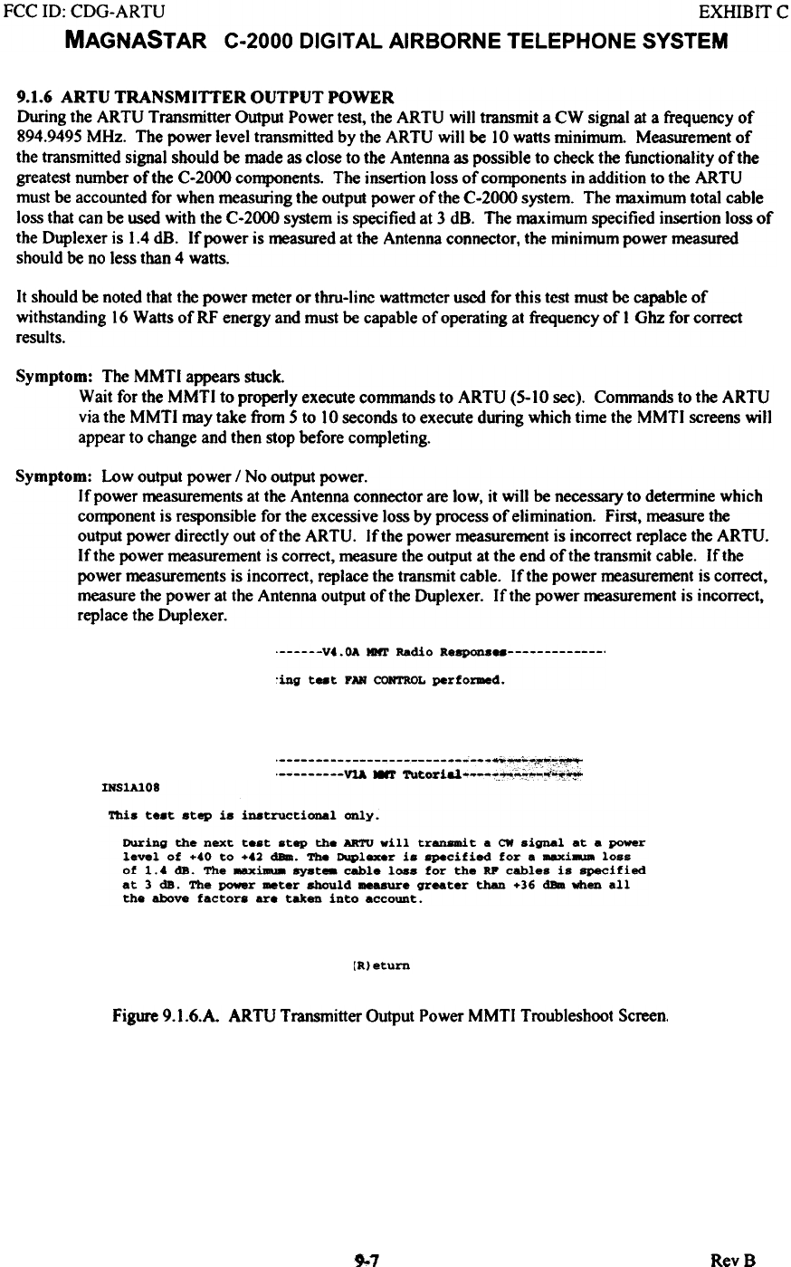
9.1.6 ARTU TRANSMITTER OUTPUT POWER
During the ARTU Transmitter Output Power test, the ARTU will transmit a CW signal at a frequency of
894.9495 MHz. The power level transmitted by the ARTU will be 10 watts minimum. Measurement of
the transmitted signal should be made as close to the Antenna as possible to check the functionality of the
greatest number of the C-2000 components. The insertion loss of components in addition to the ARTU
must be accounted for when measuring the output power of the C-2000 system. The maximum total cable
loss that can be used with the C-2000 system is specified at 3 dB. The maximum specified insertion loss of
the Duplexer is 1.4 dB. If power is measured at the Antenna connector, the minimum power measured
should be no less than 4 watts.
It should be noted that the power meter or thru-line wattmeter used for this test must be capable of
withstanding 16 Watts of RF energy and must be capable of operating at frequency of I Ohz for correct
results.
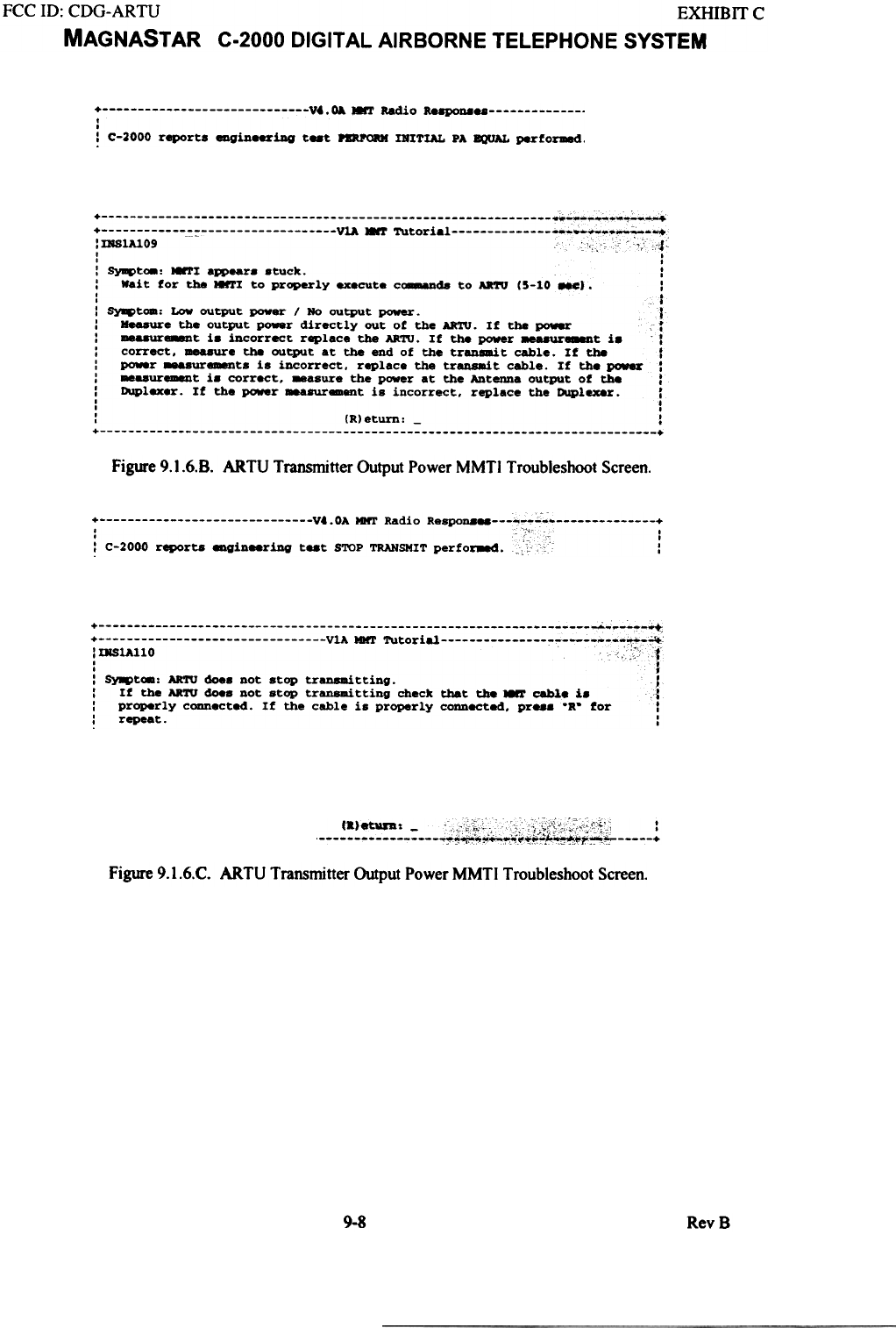
Symptom: The MMTI appears stuck.
Wait for the MMTI to properly execute commands to ARTU (5-10 sec). Commands to the ARTU
via the MMTI may take from 5 to 10 seconds to execute during which time the MMTI screens will
appear to change and then stop before completing.
Symptom: Low output power / No output power.
If power measurements at the Antenna connector are low, it will be necessary to determine which
component is responsible for the excessive loss by process of elimination. First, measure the
output power directly out of the ARTU. If the power measurement is incorrect replace the ARTU.
If the power measurement is correct, measure the output at the end of the transmit cable. If the
power measurements is incorrect, replace the transmit cable. If the power measurement is correct,
measure the power at the Antenna output of the Duplexer. If the power measurement is incorrect,
replace the Duplexer.
V.. OA MMT Radio Respons '
'ing teat FAN CONTROL perfo~d.
:::::::::: ~ - ~- ~~;w::::7J;~~
DfSlAl08
This t..t step is inatructional only.
During the next test step the ARTU will transmit a CW signal at a power
level of +40 to +42 dBm. The Duplexer is specified for a n8Xi.u. loss
of 1.4 dB. The 8aXimu8 syat.. C8ble loas for the RP cables is specified
at 3 dB. The ~r _ter should measure greater than +36 dBm when all
the above factors are taken into account.
[aleturn
Figure 9.1.6.A. ARTU Transmitter Output Power MMTI Troubleshoot Screen.
,,"1 RevS
FCC ill: CDG-ARTU EXHmrr C
MAGNAST AR C-2000 DIGITAL AIRBORNE TELEPHONE SYSTEM
+ ~.~ MMT Radio R88p0D8" t
i C-2000 reports eagiDeeriDQ teat ~ INITIAL PA ~ perfo~.
,DS1Al09 , v4~
,
I :
: ~t~: 81'1 aR>ear. .tuck. :
: Wait for tha *1'I to properly .-cute c~ to AR'fU (5-10 Me). :
: t
: ~t08: Low output power / No output power. T
: H.-ure the output p~r directly out of the AR'ro. If the power r
: me&8Ur..-Dt i. incorrect replace the AR'ro. If the power 8ea8Ur888Dt i. 1
: correct. -=e the output at the end of the tran~t cable. If the .f
: power _.ur-ts is incorrect. replace the tr~t cable. If the ~ :
: -..ur~t i. correct. _sure the power at the Antenna output of the :
: Duplex8r. If the power 88a8Ur8ment is incorrect. replace the Duplexer. t
, ..
, .
: (R)eturn: - :
+ +
Figure 9.1.6.8. ARTU Transmitter Output Power MMTI Troubleshoot Screen.
7 Vt.OA MItT Radio Resp0n8 "~::.~ 7
! C-2000 reporta engineeriD9 teat STOP TRANSMIT perfor8ed. ::i :
,DlS1Al10 c c" -1
, ..
, ,
: ~t_: ARTU does not stop tran8lRitting. l
: If the ARTIS does not stop transmitting check that the ~ ~. 1. '1
: properly eonneeted. If the cable is properly connected. pr..s "R- for 1
: repeat. :
~
Figure 9.1.6.C. ARTU Transmitter Output Power MMTI Troubleshoot Screen.
9-8 RevB
FCC ID: CDG-ARTU EXHIBIT C
MAGNASTAR C-2000 DIGITAL AIRBORNE TELEPHONE SYSTEM
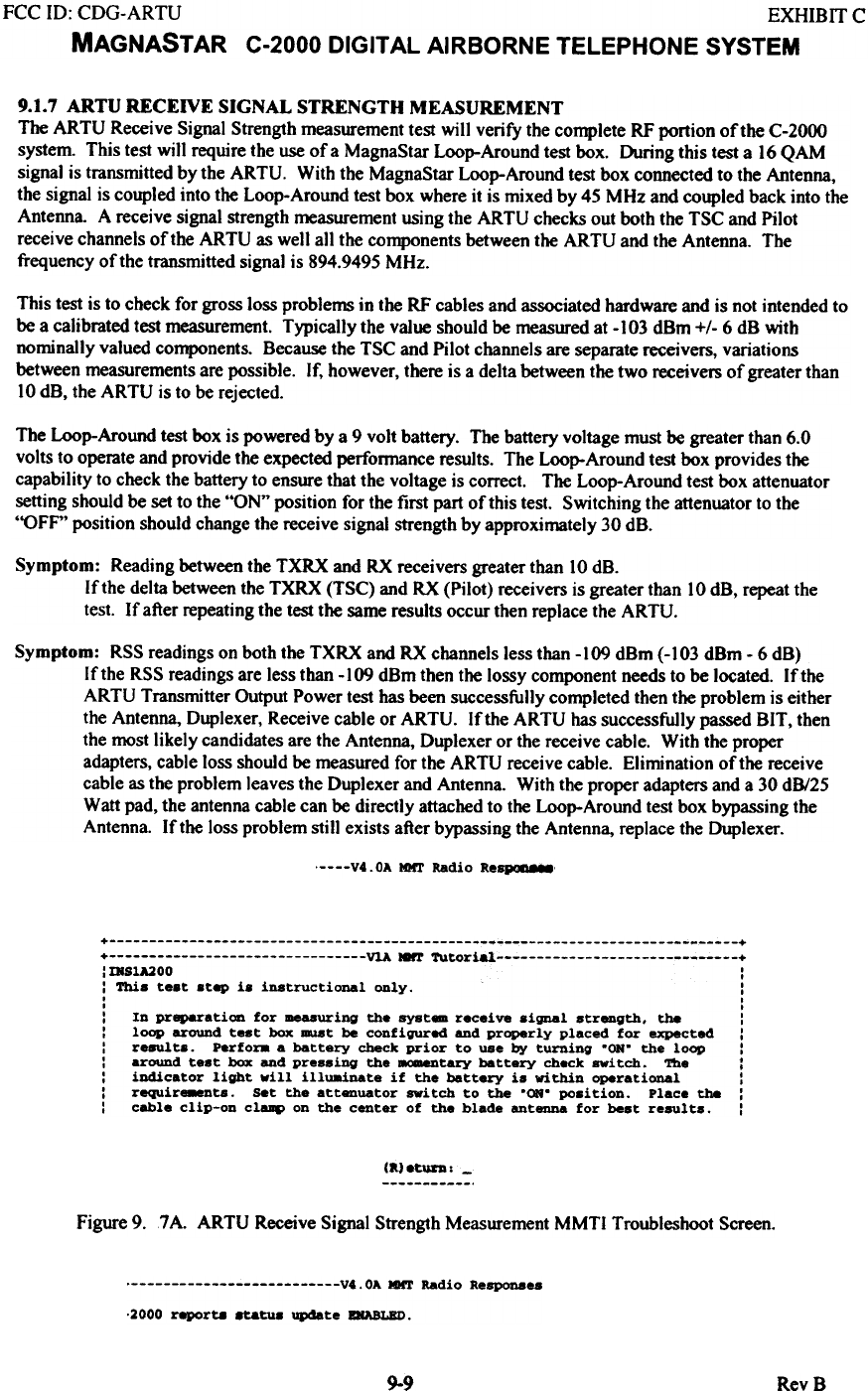
9.1.7 ARTU RECEIVE SIGNAL STRENGTH MEASUREMENT
The ARTU Receive Signal Strength measurement test will verify the complete RF portion of the C-2000
system. This test will require the use of a MagnaStar Loop-Around test box. During this test a 16 QAM
signal is transmitted by the ARTU. With the MagnaStar Loop-Around test box connected to the Antenna,
the signal is coupled into the Loop-Around test box where it is mixed by 45 MHz and coupled back into the
Antenna. A receive signal strength measurement using the ARTU checks out both the TSC and Pilot
receive channels of the ARTU as well all the components between the ARTU and the Antenna. The
frequency of the transmitted signal is 894.9495 MHz.
This test is to check for gross loss problems in the RF cables and associated hardware and is not intended to
be a calibrated test measurement. Typically the value should be measured at - 103 dBm +/- 6 dB with
nominally valued components. Because the TSC and Pilot channels are separate receivers, variations
between measurements are possible. If, however, there is a delta between the two receivers of greater than
10 dB, the ARTU is to be rejected.
The Loop-Around test box is powered by a 9 volt battery. The battery voltage must be greater than 6.0
volts to operate and provide the expected perfonnance results. The Loop-Around test box provides the
capability to check the battery to ensure that the voltage is correct. The Loop-Around test box attenuator
setting should be set to the "ON" position for the first part of this test. Switching the attenuator to the
"OFF" position should change the receive signal strength by approximately 30 dB.
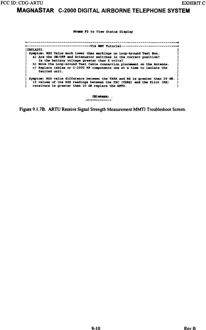
Symptom: Reading between the TXRX and RX receivers greater than 10 dB.
If the delta between the TXRX (TSC) and RX (Pilot) receivers is greatertban 10 dB, repeat the
test. If after repeating the test the same results occur then replace the ARTU.
Symptom: RSS readings on both the TXRX and RX channels less than -109 dBm (-103 dBm - 6 dB)
If the RSS readings are less than -109 dBm then the lossy component needs to be located. If the
ARTU Transmitter Output Power test has been successfully completed then the problem is either
the Antenna, Duplexer, Receive cable or ARTU. If the ARTU has successfully passed BIT, then
the most likely candidates are the Antenna, Duplexer or the receive cable. With the proper
adapters, cable loss should be measured for the ARTU receive cable. Elimination of the receive
cable as the problem leaves the Duplexer and Antenna. With the proper adapters and a 30 dB/25
Watt pad, the antenna cable can be directly attached to the Loop-Around test box bypassing the
Antenna. If the loss problem still exists after bypassing the Antenna, replace the Duplexer.
, V4. OA 10ft' Radio ReSPO8'8M
+ ~ +
+ VlA IGrr TutorW;' +
'mS1A200 I
I I
: This test step i8 instructional only. :
I ,
I I
: In preparation for measuring the syst.. receive 8ignal strength. the :
: loop around test box -.t be configured and properly placed for expected :
: results. Perfora a battery check prior to use by turning .ON. the loop :
: around test box and pressing the -.ntary battery check _itch. 'ft1e :
: indicator light vill illU8inate if the battary is within operational :
: require8eDts. set the attenuator svitch to the .ON. position. Place the :
: cable clip-on cla.p on the center of the blade antenna for best results. :
(a}~.-
Figure 9. 7 A. ARTU Receive Signal Strength Measurement MMTI Troubleshoot Screen.
' V4.0A MMT Radio Responses
.2000 ~rta .tatu. update ENABLED.
9-9 RevB
FCC ill: CDG-ARTU EXHIBIT C
MAGNASTAR C-2000 DIGITAL AIRBORNE TELEPHONE SYSTEM
Pr'-' F2 to View Status Display
+ +
+ VlA I8rr Tutorial :mSlA20l :
: SY8f{)tom, us Value alUch lower than ~kings on Loop-Around Teat Box. :
: a) Are the ON/OFF and Attenuator awitches in the correct po8ition? :
: Is the battery voltage greater than 6 volts? :
: b) .ove ~e Loop-Around Test Cable connection plac_t on the Ant~a. :
: c) Replace cables or C-2000 RP components one at a time to isolate the :
: faulted unit. :
I I
. I
: ~t_, RSS value difference bet_en the TXRX and RX is gre.ter than 10 dB. :
: If values of the US readings bet_en the TSC (TXRX) and the Pilot (RX) :
: receivers is greater than 10 dB replace the ARTU. :
._"'~~:_:
Figure 9.1.7B. ARTU Receive Signal Strength Measurement MMTI Troubleshoot Screen.
9-10 RevB
FCC 10: CDG-ARTU EXHIBIT C
MAGNASTAR C-2000 DIGITAL AIRBORNE TELEPHONE SYSTEM
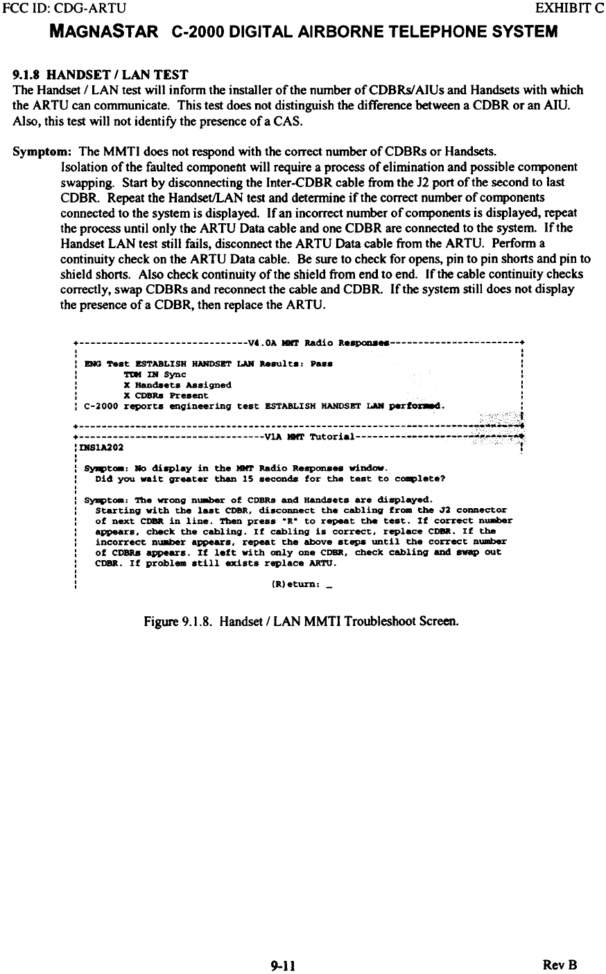
9.1.8 HANDSET I LAN TEST
The Handset I LAN test wilt inform the installer of the number ofCDBRs/AIUs and Handsets with which
the ARTU can cornrnunicate. This test does not distinguish the difference between a CDBR or an Am.
Also, this test will not identify the presence of a CAS.
Symptom: The MMTI does not respond with the correct number of CDBRs or Handsets.
Isolation of the faulted componellt will require a process of elimination and possible component
swapping. Start by disconnecting the Inter-CDBR cable from the 12 port of the second to last
CDBR. Repeat the Handset/LAN test and determine if the correct number of components
connected to the system is displayed If an incorrect number of components is displayed, repeat
the process until only the ARTU Data cable and one CDBR are connected to the system. If the
Handset LAN test still fails, disconnect the ARTU Data cable from the ARTU. Perform a
continuity check on the ARTU Data cable. Be sure to check for opens, pin to pin shorts and pin to
shield shorts. Also check continuity of the shield from end to end. If the cable continuity checks
correctly, swap CDBRs and reconnect the cable and CDBR. If the system still does not display
the presence of a CDBR, then replace the ARTU.
+ V4.0A MNT Radio Re~ +
I I
I I
: DIG Test ESTABLISH HANDSET LAN Result.. Pas. :
: TDI IN Sync :
: X Handsets Assigned :
: X CDBRa Present :
: C-2000 reports engineering test ESTABLISH HANDSBT LAN perfOC8.d. :
:mS1A202 ." C i
I
I
: ~t_: Ro di8Play in the IDtr Radio RaSP0D888 window.
: Did you wait greater than 15 seconds for the test to c~lete?
,
,
: SyqItoa: The wrong nU8ber of CDBRs and Handsets are displayed.
: Starting with the last CDBR, disconnect the cabling from the J2 connector
: of next CDBR in line. Then press .R. to repeat the test. If correct nU8ber
: appears, check the cabling. If cabling is correct, replace CDBR. If the
: incorrect nU8ber appears, repeat the above steps until the correct number
: of COBRa appears. If left with only one CDBR, check cabling and swap out
: CDBR. If problem still exists replace ARTU.
,
,
: (R)eturn: -
Figure 9.1.8. Handset / LAN MMTI Troubleshoot Screen.
RevB
9-11
FCC ill: CDG-ARTU EXHIBIT C
MAGNASTAR C-2000 DIGITAL AIRBORNE TELEPHONE SYSTEM
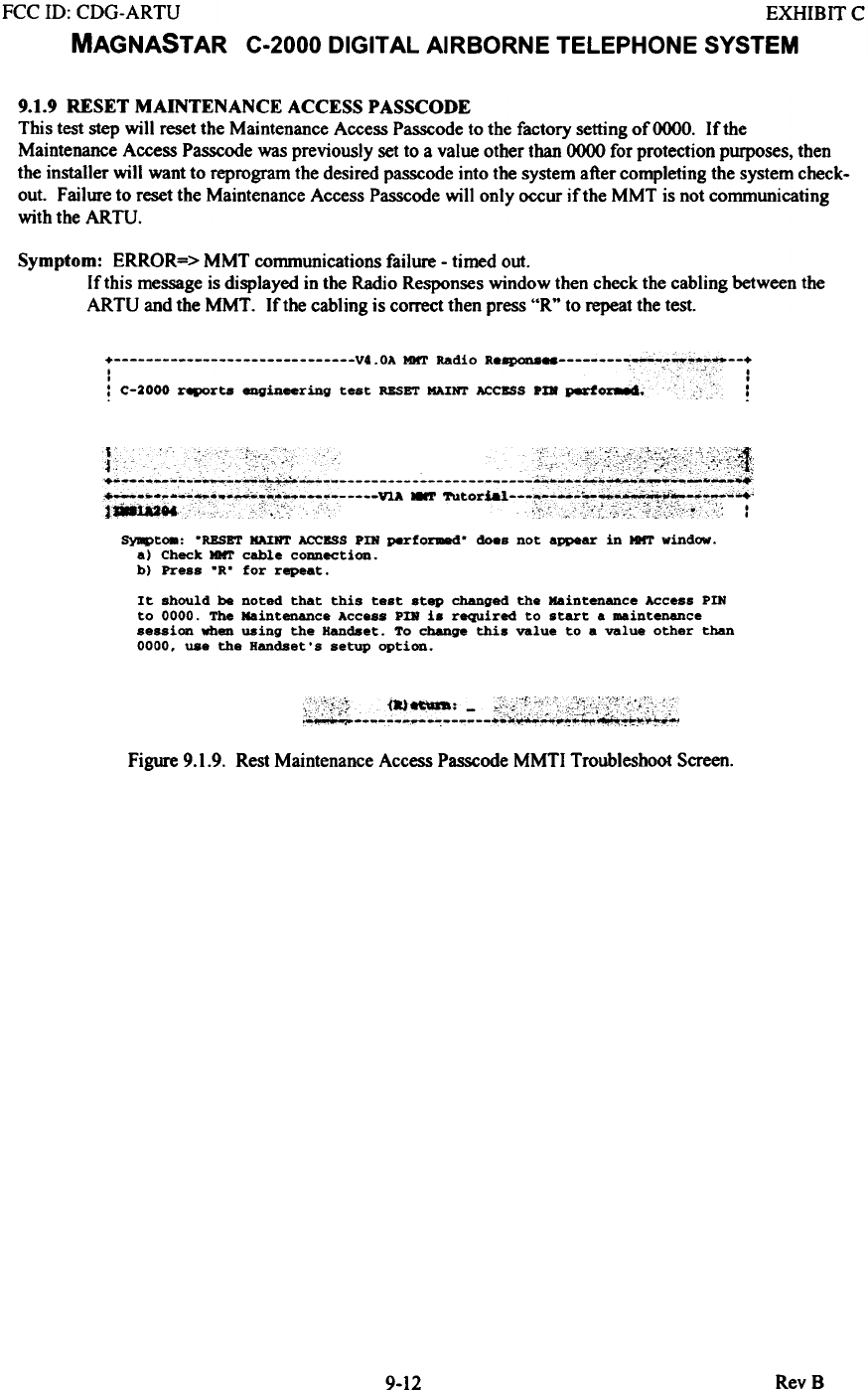
9.1.9 RESET MAINTENANCE ACCESS P ASSCODE
This test step will reset the Maintenance Access Passcode to the factory setting of 0000. If the
Maintenance Access Passcode was previously set to a value other than 0000 for protection purposes, then
the installer will want to reprogram the desired passcode into the system after completing the system check-
out. Failure to reset the Maintenance Access Passcode will only occur if the MMT is not communicating
with the ARTU.
Symptom: ERROR=> MMT communications failure - timed out.
If this message is displayed in the Radio Responses window then check the cabling between the
ARTU and the MMT. If the cabling is correct then press "Rtt to repeat the test.
i V4. OA MMT Radio R.~ ~~~-:t~--i
! C-2000 ~rta eDgineering test RESET DINT ACCESS pm perf~ ..!
~
~t08: .RESET KA:INT ACCESS PDi perfo~. does not appear in IDrr window.
a) Check IDrr cable connection.
b) Press .R. for repeat.
It should be noted that this test step changed the Maintenance Access PIN
to 0000. The Maintenance Acce.. PDi is required to start a maintenance
session when using the Handset. To change this value to a value other than
0000. use the Handset. s setup option.
~
Figure 9.1.9. Rest Maintenance Access Passcode MMTI Troubleshoot Screen.
9-12 RevS