Raytheon IIS ARTU Air-Ground Radio System User Manual installation manual part five
Raytheon Company Air-Ground Radio System installation manual part five
Contents
installation manual part five
EXHIBrrc
C-2000 DIGITAL AIRBORNE TELEPHONE SYSTEM
FCC ID: COO-ARTU
MAGNASTAR
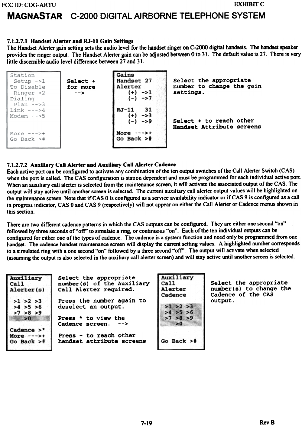
7.1.2.7.1 Handset Alerter and RJ-ll Gain Settings
The Handset Alerter gain setting sets the audio level for the handset ringer on C-2000 digital handsets. The handset speaker
provides the ringer output. The Handset Alerter gain can be adjusted between 0 to 31. The default value is 27. There is very
little discernible audio level difference between 27 and 31.
Select +
for more
-->
Select the appropriate
number to change the gain
settings.
Gains
Handset 27
Alerter
(+) ->1
(-) ->7
31
->3
->9
RJ-l
Select + to reach other
Handset Attribute screens
More --->..
Go BAck >1
7.1.2.7.2 Auxiliary Call Alerter and Auxiliary Call Alerter Cadenee
Each active port can be configured to activate any combination of the ten output switches of the Call Almer Switch (CAS)
when the port is called. The CAS configuration is station dependent and must be programmed for each individual active port.
When an aux.iliary call aImer is selected from the maintenance screen, it will activate the associated output oftbe CAS. The
output will stay active until another screen is selected. The current aux.iliary call alerter output values will be highlighted on
the maintenance screen. Note that if CAS 0 is configured as a service availability indicator or if CAS 9 is configured as a call
in progress indicator, CAS 0 and CAS 9 (respectively) will not appear on either the Call Almer or Cadence menus shown in
this section.
There are two different cadence patterns in which the CAS outputs can be configured. They are either one second "on"
followed by three seconds of "off' to simulate a ring, or continuous "on". Each of the ten individual outputs can be
configured for either one of the types of cadence. The cadence is a system function and need only be programmed from one
handset. The cadence handset maintenance screen will display the current setting values. A highlighted number corresponds
to a simulated ring with a one second "on" followed by a three second "off'. The output will activate when selected
(assuming the output is also selected in the auxiliary call alerter screen) and will stay active until another screen is selected.
Auxiliary-
Call
Alerter
Cadence
Select the appropriate
number(s) of the Auxiliary
Call Alerter required. Select the appropriate
number(s) to change the
Cadence of the CAS
output.
Auxiliary
Call
Alerter(s)
>1 >2 >3
>4 >5 >6
>7 >8 >9
J~.~, >o"{i
Press the number again to
deselect an output. >1>2 >3
>4 >5 >6
>7 >8~9
>0
Press * to view the
Cadence screen. -->
Cadence >*
More --->+
Go Back >1 Press + to reach other
handset attribute screens Go Back >1
RevS
7-19
FCC 10: CDG-ARTU
MAGNASTAR
EXHIBrrc
C-2000 DIGITAL AIRBORNE TELEPHONE SYSTEM
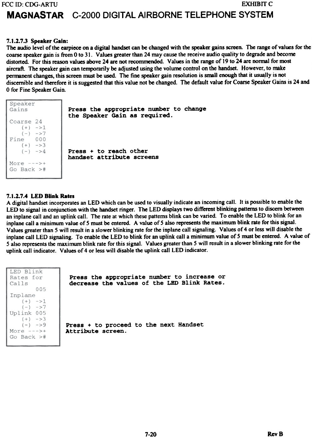
7.1.2.7.3 Speaker Gain:
The alJdjo level of the earpiece on a digital handset can be changed with the speaker gains screen. The range of val~ for the
coarse speaker gain is from 0 to 31. Values greater than 24 may cause the receive audio quality to degrade and become
distorted. For this reason values above 24 are not recommended. Values in the range of 19 to 24 are normal for most
aircraft. The speaker gain can temporarily be adjusted using the volume control on the handset. However, to make
pennanent changes, this screen must be ~ The fine speaker gain resolution is small enough that it usua.lly is not
discernible and therefore it is suggested that this value not be changed. The default value for Coarse Speaker Gains is 24 and
0 for Fine Speaker Gain.
Press the appropriate number to change
the Speaker Gain as required.
Press + to reach other
handset attribute screens
7.1.2.7.4 LED BUnk Rates
A digital handset incorporates an LED which can be used to visually indicate an incoming call. It is possible to enable the
LED to sjgnal in conjunction with the handset ringer. The LED displays two different blinkjng patterns to discern between
an inplane call and an uplink call. The rate at which these patterns blink can be varied. To enable the LED to blink for an
inplane call a minimum value of 5 must be entered. A value of 5 also represents the maximum blink rate for this sjgnal.
Values greater than 5 will result in a slower blinking rate for the inplane call signaling. Values of 4 or less will disable the
inplane call LED signaling. To enable the LED to blink for an uplink call a minimum value of 5 must be entered. A value of
5 also represents the maximum blink rate for this sjgnal. Values greater than 5 will result in a slower blinkjng rate for the
uplink call indicator. Values of 4 or less will disable the uplink call LED indicator.
Press the appropriate number to increase or
decrease the values of the LED Blink Rates.
Press + to proceed to the next Handset
Attribute screen.
RevS
7-20
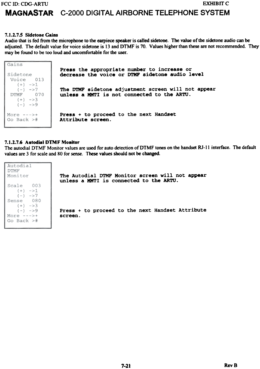
EXHIBIT C
C-2000 DIGITAL AIRBORNE TELEPHONE SYSTEM
FCC ID: CDG-ARTU
MAGNASTAR
7.1.2.7.5 Sidetone Gains
Audio that is fed from the microphone to the earpiece speaker is called sidetooe. The value of the sidetone audio can be
adjusted. The default value for voice sidetone is 13 and DTMF is 70. Values higher than these are not recommended. They
may be found to be too loud and uncomfortable for the user.
Press the appropriate number to increase or
decrease the voice or DTMP sidetone audio level
The DTMF sidetone adjustment screen will not appear
unless a MMTI is not connected to the ARTU.
Press + to proceed to the next Handset
Attribute screen.
7.1.1.7.6 Autodial DTMF Mo8itor
The autodial DTMF Monitor values are used for auto detection of DTMF tones on the handset RJ-II interface. The default
values are 3 for scale and 80 for sense. These values should not be changed
The Autodial DTMF Monitor screen will not appear
unless a MMTI is connected to the ARTU.
Press + to proceed to the next Handset Attribute
screen.
1-21 RevB
FCC 10: CDG-ARTU
MAGNASTAR
EXHIBIT C
C-2000 DIGITAL AIRBORNE TELEPHONE SYSTEM
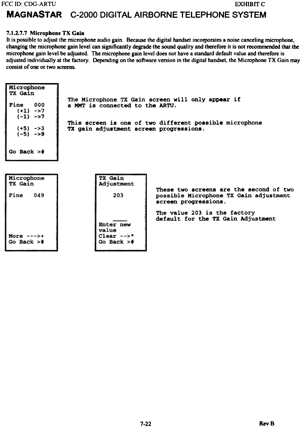
7.1.2.7.7 MicrophoneTXGain
It is possible to adjust the microphone audio gain. Because the digital handset incorporates a noise canceling microphone,
changing the microphone gain level can significantly degnide the sound quality and therefore it is not recommended that the
microphone gain level be adjusted. The microphone gain level does not have a standard default value and therefore is
adjusted individually at the factory. Depending on the software version in the digital handset, the Microphone TX Gain may
consist of one or two screens.
~ophone
TX Gain The Microphone TX Gain screen will only appear if
a MMT is connected to the ARTU.
Pine 000
(+1) ->7
(-1) ->7 This screen is one of two different possible microphone
TX gain adjustment screen progressions.
(+5) ->3
(-5) ->9
Go Back >1
~rophOne
TX Ge.it' TX Gain
Adjustment These two screens are the second of two
possible Microphone TX Gain adjustment
screen progressions.
049 20.1
Pine
The value 203 is the factory
defaul t for the TX Gain Adjustment
Enter new
value
Clear -->*
Go Back >1
More --->+
Go Back >1
RevS
7-22
FCC 10: CDG-ARTU
MAGNASTAR
EXHIBffC
C-2000 DIGITAL AI RBORNE TELEPHONE SYSTEM
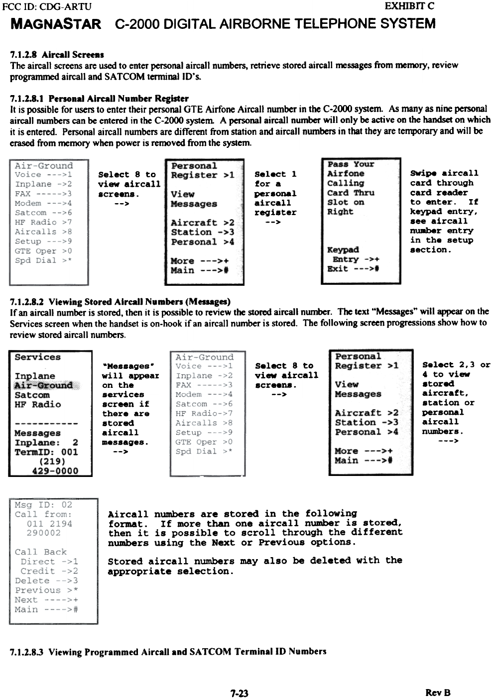
7.1.2.8 Airall Sereeas
The aircall screens are used to enter personal aircall numbers, retrieve stored aircall messages from memory, review
programmed aircall and SA TCOM terminal ID's.
7.1.1.8.1 Personal AireaU Number Register
It is possible for users to enter their personal GTE Airfone Aircall number in the C-2000 system As many as nine personal
aircaJl numbers can be entered in the C-2000 system A personal aircall number will only be active on the handset on which
it is entered. Personal aircall numbers are different from station and aircall numbers in that they are temporary and will be
erased from memory when power is removed from the system
,... Your
Airfone
Calling
Card Thru
Slot on
Right
Select 8 to
view aircall
8creens.
-->
-
Personal
Register >1 Select I
for a
personal
aircall
register
-->
View
Messages
SWipe aircall
card through
card reader
to enter. If
keypad entry,
see aircall
nuRber entry
in the setup
section.
Aircraft >2
Station ->3
Personal >4 Keypad
Entry
Exit - ,>+
,>t
More --->...
Main --->f
7.1.2.8.2 Viewing Stored AircaU NumbeR (Messages)
If an aircall number is stored, then it is possible to review the stored aircaJI nwnber. The text "Messages" will appear on the
Services screen when the handset is on-hook if an aircall number is stored. The following screen progressions show how to
review stored aircall numbers.
Services Personal
Register >1 Select 2,3 or
4 to view
.tored
aircraft,
station or
personal
aircall
numbers.
--->
-Messages.
will appear
on the
services
screen if
there are
stored
aircall
messages.
-->
Select 8 to
view aircall
scre8D8.
--> view
Messages
Inplane
Air-Ground
Satcom
HF Radio Aircraft >2
Station ->3
Personal >4
Messages
Inplane: 2
TermID: 001
(219)
429-000~
More --->+
Main --->of
Aircall numbers are stored in the following
format. If more than one aircall number is stored.
then it is possible to scroll through the different
numbers using the Next or Previous options.
Stored aircall numbers may also be deleted with the
appropriate selection.
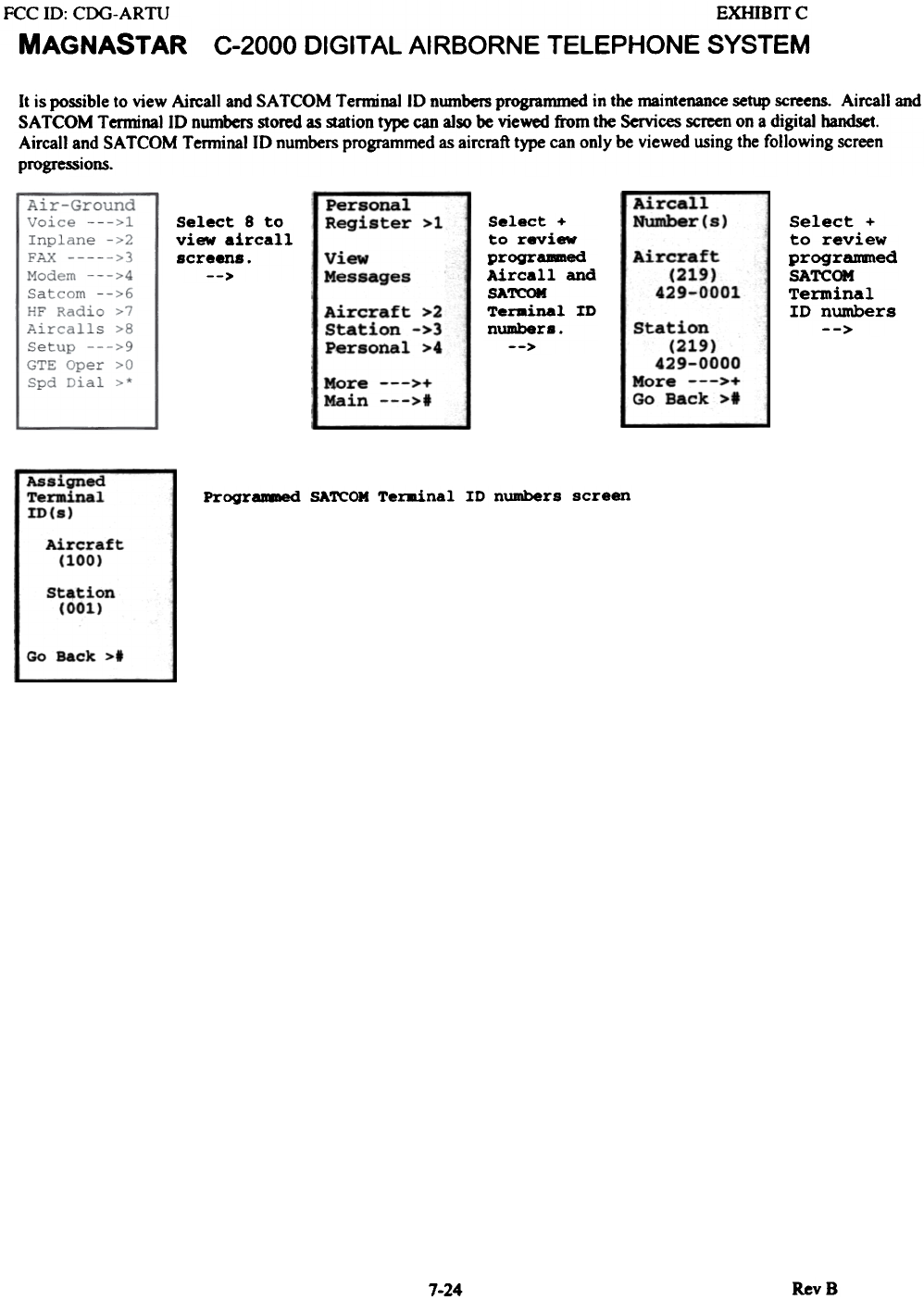
7.1.2.8.3 Viewing Programmed AircaU and SATCOM TerminallD Numbers
RevB
7-23
EXHIBrrc
C-2000 DIGITAL AIRBORNE TELEPHONE SYSTEM
FCC ill: CDG-ARTU
MAGNASTAR
It is possible to view Aircall and SA TCOM TenninallD numbers programmed in the maintenance setup screens. Aircall and
SA TCOM TenninaliD numbers stored as station type can also be viewed from the Services screen on a digital handset.
Ajrcall and SA TCOM T enninallD numbers programmed as aircraft type can only be viewed using the following screen
progressions.
AIrc-all
Number (8)
Select 8 to
view aircall
screens.
-->
Personal
Register >1 Select +
to review
progr.-ed
Aircall and
SAreOM
Te~inal ID
number. .
-->
Select +
to review
progr8Jm\ed
SA'l'COM
Terminal
ID numbers
-->
Aircraft
(219)
429-0001
view
Messages
Aircraft >2
Station ->3
Personal >4 Station
(219)
429-0000
More --->+
Go Back >1
More --->+
Main --->1
Assigned
Terminal
ID(s) PrograJl8led SATCOM Terminal ID numbers screen
Aircraft
(100)
Station
IOOl)
Go Back >1
RevB
7-24
EXHIBITC
C-2000 DIGITAL AIRBORNE TELEPHONE SYSTEM
FCC 10: CDG-ARTU
MAGNASTAR
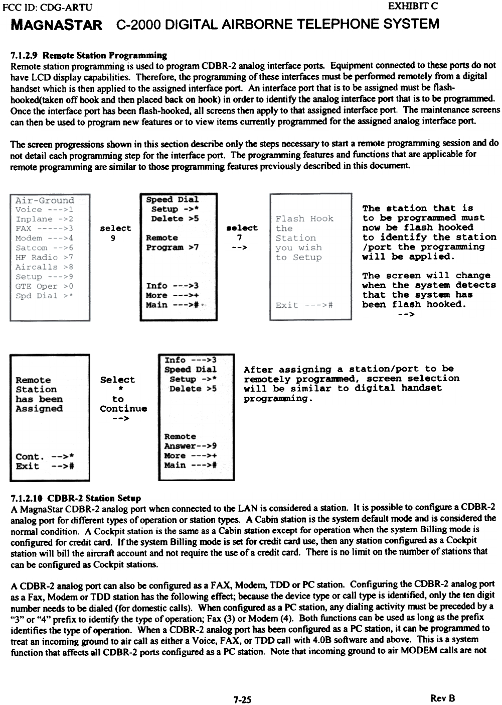
7.1.2.9 Remote Station Programming
Remote station programming is used to program CDBR-2 analog interface ports. Equip~nt connected to these ports do not
have LCD display capabilities. Therefore, the programming of these interfaces must be performed remotely from a digital
handset which is then applied to the assigned interface port. An interface port that is to be assigned must be flash-
hooked(taken off hook and then placed back on hook) in order to identify the analog interface port that is to be programmed.
Once the interface port has been flash-hooked, all screens then apply to that assigned interface port. The maintenance screens
can then be used to program new features or to view items currently programmed for the assigned analog interface port.
The screen progressions shown in this section describe only the steps necessary to start a remote programming session and do
not detail each programming step for the interface port. The programming features and functions that are applicable for
remote programming are similar to those programming features previously described in this document.
-Speed- Dial
Setup ->*
Delete >5 The station that is
to be prograDBned must
now be flash hooked
to identify the station
/port the programming
will be applied.
select
9.elect
7
-->
Remote
Program >/
The screen will change
when the system detects
that the system has
been flash hooked.
-->
Info --->3
More --->+
_in --->f
Info --->3
Speed Dial
Setup ->*
Delete >5
Select
*
to
Continue
-->
Remote
Station
has been
Assigned
After assigning a station/port to be
remotely programmed, screen selection
will be similar to digital handset
prograDming.
Remote
Answer-->9
More --->+
Main --->1
Cant
Exit -->-
--,-,
7.1.2.10 CDBR-2 Station Setup
A MagnaStar CDBR-2 analog port when connected to the LAN is considered a station. It is possible to configure a CDBR-2
analog port for different types of operation or station types. A Cabin station is the system default mode and is considered the
normal condition. A Cockpit station is the same as a Cabin station except for operation when the system Billing mode is
configured for credit card. If the system Billing roode is set for credit card use, then any station configured as a Cockpit
station will bill the aircraft account and not require the use of a credit card. There is no limit on the number of stations that
can be configured as Cockpit stations.
A CDBR-2 analog port can also be configured as a FAX, Modem, TDD or PC station. Configuring the CDBR-2 analog port
as a Fax, Modem or TDD station has the following effect; because the device type or call type is identified, only the ten digit
number needs to be dialed (for do~c calls). When configured as a PC station, any dialing activity must be preceded by a
"3" or "4" prefix to identify the type of operation; Fax (3) or Modem (4). Both functions can be used as long as the prefix
identifies the type of operation. When a CDBR-2 analog port has been configured as a PC station, it can be programmed to
treat an incoming ground to air call as either a Voice, FAX, or roD call with 4.0B software and above. This is a system
function that affects all CDBR-2 ports configured as a PC station. Note that incoming ground to air MODEM calls are not
RevS
7-25
EXHIBrrc
C-2000 DIGITAL AIRBORNE TELEPHONE SYSTEM
FCC 10: CDG-ARTU
MAGNASTAR
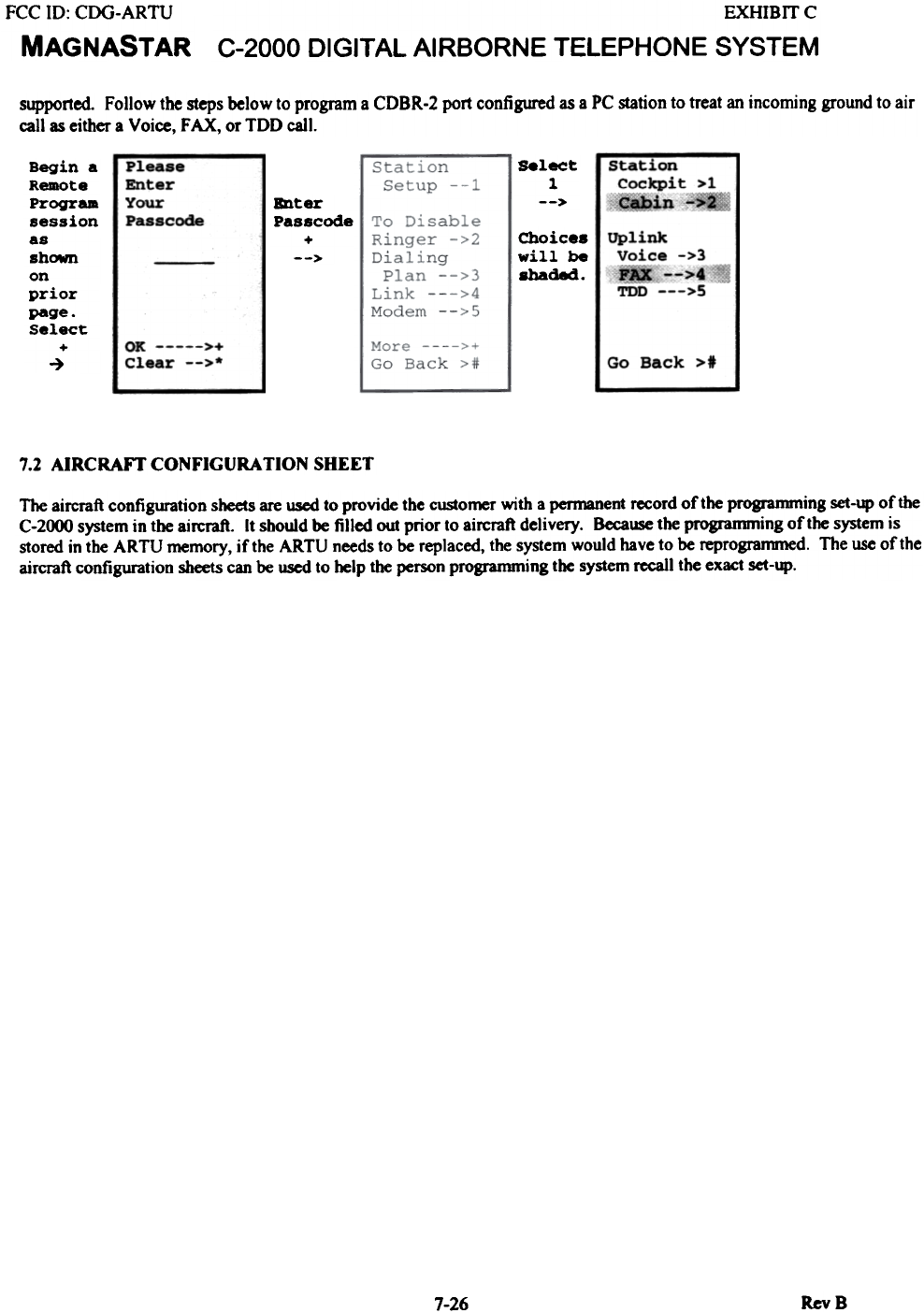
supported. Follow the steps below to program a CDBR-2 port configured as a PC station to treat an incoming ground to air
call as either a Voice, FAX, or TDD call.
Select
1
--~
Begin a
Remote
Program
session
as
shC*n
on
prior
page.
Select
+
~
station
cockpit >1
«ibin ~
Enter
pas.code
+
-->
nea..-
Enter
Your
Passc~ Choice.
will be
shaded .
Uplink
Voice ->3
.. -->.
TDD --->!
OK >+
Clear -->* Go Back >t
7.2 AIRCRAFT CONFIGURATION SHEET
The aircraft configuration sheets are used to provide the customer with a permanent record of the progrannning set-up of the
C-2000 system in the aircraft. It should be filled out prior to aircraft delivery. Because the programming of the system is
stored in the ARTU memory, if the ARTU needs to be replaced, the system would have to be reprogrammed. The use of the
aircraft configuration sheets can be used to help the person programming the system recall the exact set-up.
7-26 RevB