Raytheon IIS ARTU Air-Ground Radio System User Manual installation manual part seven
Raytheon Company Air-Ground Radio System installation manual part seven
Contents
installation manual part seven
FCC ID: CDG-ARTU EXHIBIT C
MAGNASTAR C-2000 DIGITAL AIRBORNE TELEPHONE SYSTEM
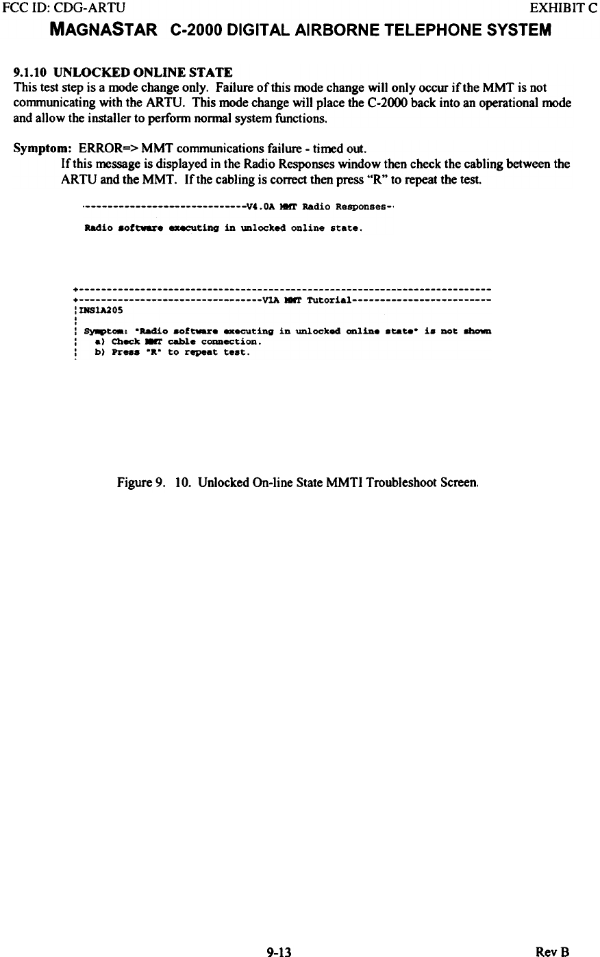
9.1.10 UNWCKED ONLINE STATE
This test step is a mode change only. Failure of this mode change will only occur if the MMT is not
communicating with the ARTU. This mode change will place the C-2000 back into an operational mode
and allow the installer to perform normal system functions.
Symptom: ERROR=> MMT communications failure - ti~d out.
If this ~ssage is displayed in the Radio Responses window then check the cabling between the
ARTU and the MMT. If the cabling is correct then press "R" to repeat the test.
V4.0A HHT Radio Responses-.
Radio 8oftwere .-.cutiDg in unlocked online state.
+ + ~ MMT TUtorial : DfS1A205
.
.
: ~t08: 'Radio aof~e executing in unlocked online state' ia not shown
: e) Check.-T cable connection.
: b) Pres. ... to repeat test.
Figure 9. 10. Unlocked On-line State MMTI Troubleshoot Screen.
9-13 RevB
FCC 10: CDG-ARTU EXHIBIT C
MAGNASTAR C-2000 DIGITAL AIRBORNE TELEPHONE SYSTEM
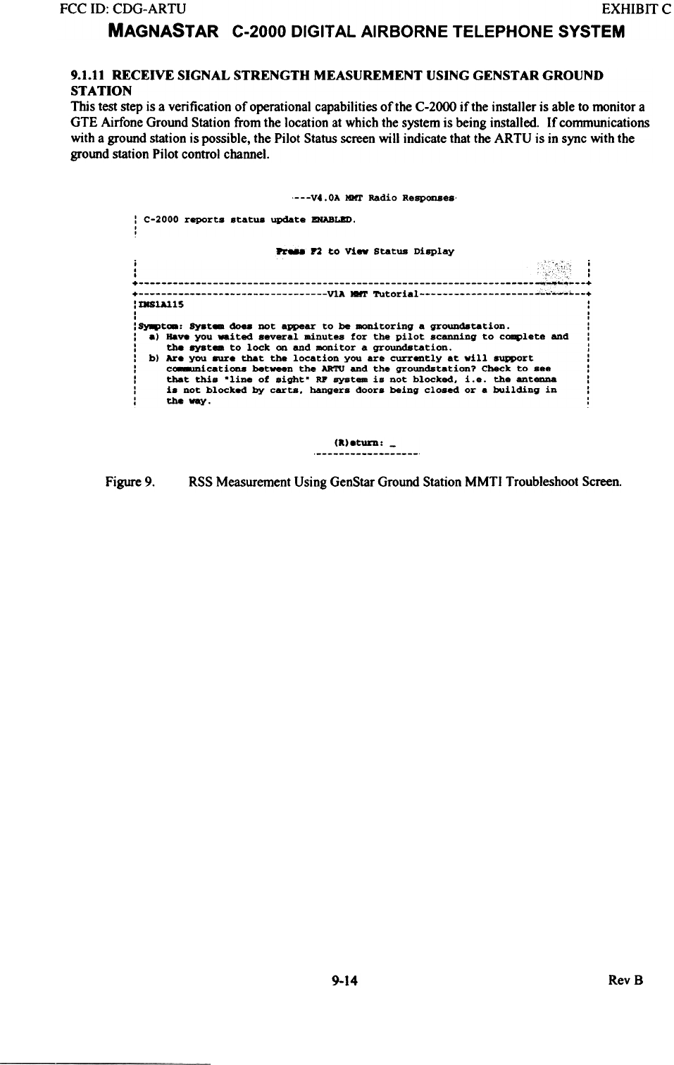
9.1.11 RECEIVE SIGNAL STRENGTH MEASUREMENT USING GENSTAR GROUND
STATION
This test step is a verification of operational capabilities of the C-2000 if the installer is able to monitor a
GTE Airfone Ground Station from the location at which the system is being installed. If communications
with a ground station is possible, the Pilot Status screen will indicate that the ARTU is in sync with the
ground station Pilot control channel.
---V4.0A MIr1' Radio Responses-
: C-2000 reports statua update ENABLED.
I
,
PrM8 r2 to Vi- Status Display
:IHS1A115 :
I I
I ,
:~t_, ay.t- cSoea DOt appear to be monitoring a grOUDdatation. :
: .) Have you waited several minutes for the pilot scanning to complete and :
: tha 8Y8t- to lock on and monitor a groundstation. :
: b) Are you 8Ure that the location you are currently at will support :
: c.-micatioos between the AR'n1 and the groundstetion? Check to see :
: that this .line of sight. RP system is not blocked. i.e. the antenna :
: i. not blocked by carta. hanger. door. being closed or a building in :
: the way. :
(a).turn: -
Figure 9. RSS Measurement Using GenStar Ground Station MMTI Troubleshoot Screen.
9-14 RevB
FCC ill: CDG-ARTU EXHIBIT C
MAGNASTAR C-2000 DIGITAL AIRBORNE TELEPHONE SYSTEM
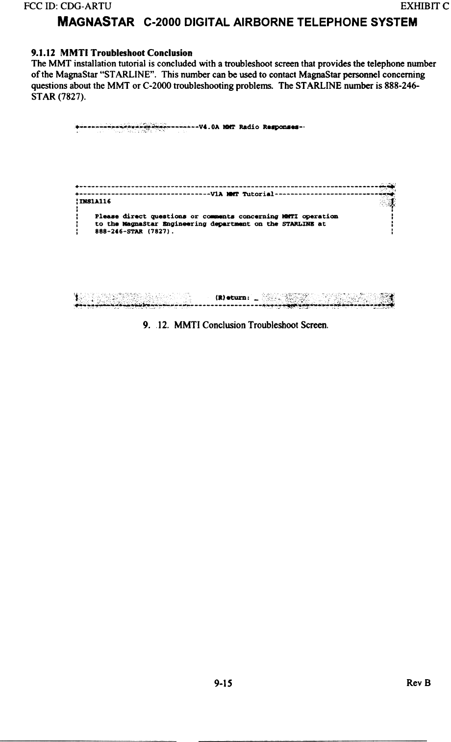
9.1.12 MMTI Troubleshoot Conclusion
The MMT installation tutorial is concluded with a troubleshoot screen that provides the telephone number
of the MagnaStar "ST ARLINE". This number can be used to contact MagnaStar personnel concerning
questions about the MMT or C-2000 troubleshooting problems. The ST ARLINE number is 888-246-
STAR (7827).
r 0,
+ o; ~ v. OA Iar1' Radio R.""""."-'
. c-;:.F~":CC-. -r-
: DfSlA1l6 c:,*
, .
: Pleas. direct questiOl18 or c~ta concerning *I'I operati- :
: to the llagnastar &1gineering d~t on the STARLDIB at :
: 888-246-STAR (7827). :
~
9. 12. MMTI Conclusion Troubleshoot Screen.
9-15 RevB
FCC ill: CDG-ARTU EXHIBIT C
MAGNASTAR C-2000 DIGITAL AIRBORNE TELEPHONE SYSTEM
9.2 Additional MMTI Troubleshoot Information
This section provides additional tests that may be used for troubleshooting or system check-out. Tests in
this section require the use of the MMTI commanded mode screens. See section 9.3 for information
detailing navigation and description of the various MMTI commanded mode screens.
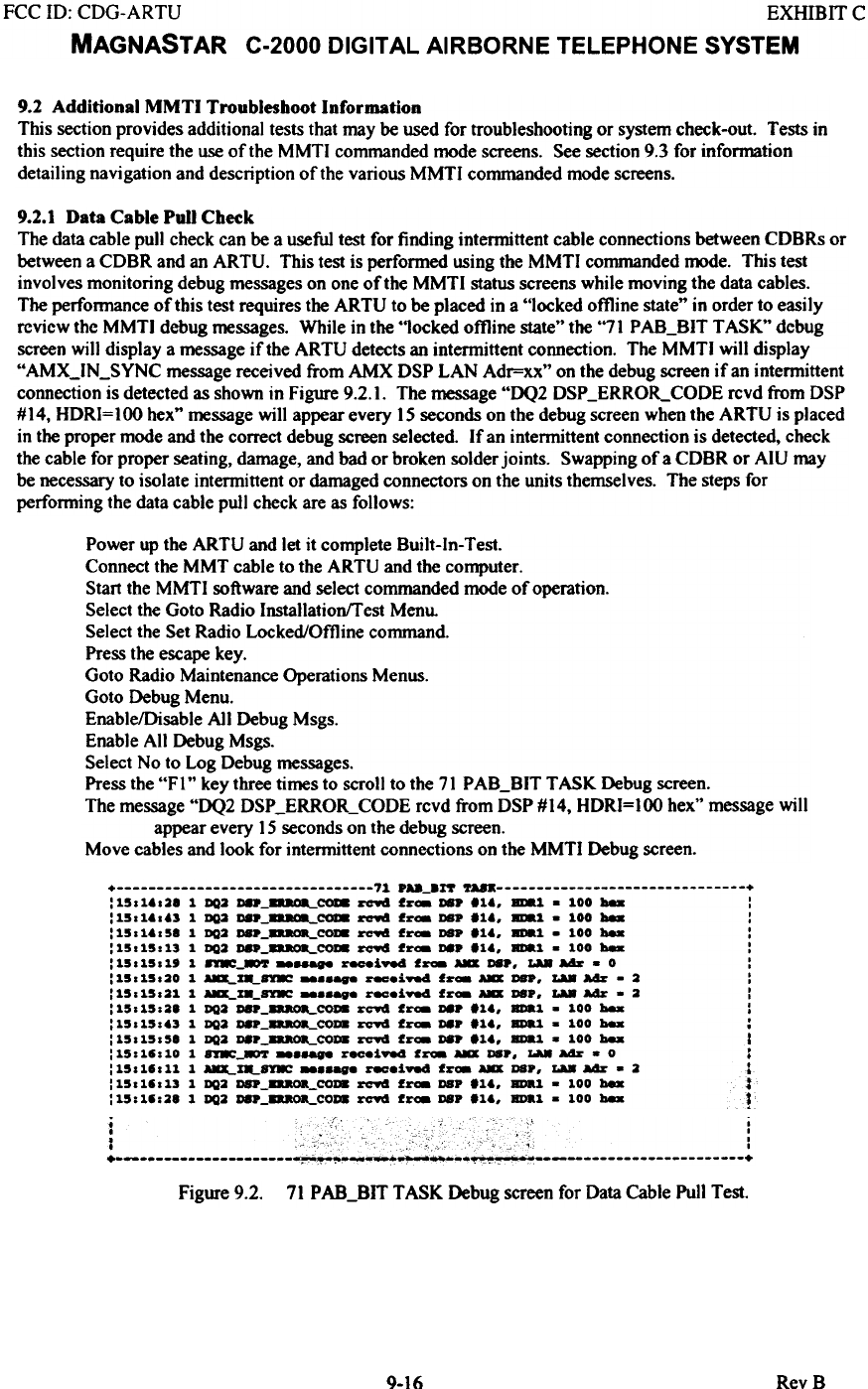
9.2.1 Data Cable Pull Check
The data cable pull check can be a useful test for finding intermittent cable connections between CDBRs or
between a CDBR and an ARTU. This test is performed using the MMTI commanded ~e. This test
involves monitoring debug messages on one of the MMTI status screens while moving the data cables.
The performance of this test requires the ARTU to be placed in a "locked offline state" in order to easily
rcvicw thc MMTI debug messages. While in the "locked offline state" the "71 P AB_BIT TASK" dcbug
screen will display a message if the ARTU detects an intermittent connection. The MMTI will display
"AMX_IN_SYNC message received from AMX DSP LAN Adr=xx" on the debug screen if an intermittent
connection is detected as shown in Figure 9.2.1. The message "DQ2 DSP _ERROR_CODE rcvd from DSP
#14, HDRI=I00 hex" message will appear every 15 seconds on the debug screen when the ARTU is placed
in the proper mode and the correct debug screen selected. If an intermittent connection is detected, check
the cable for proper seating, damage, and bad or broken solder joints. Swapping of a CDBR or AIU may
be necessary to isolate intermittent or damaged connectors on the units themselves. The steps for
perfonning the data cable pull check are as follows:
Power up the ARTU and let it complete Built-ln- Test.
Connect the MMT cable to the ARTU and the computer.
Start the MMTI software and select commanded mode of operation.
Select the Goto Radio Installation/f est Menu.
Select the Set Radio Locked/Offline command.
Press the escape key.
Goto Radio Maintenance Operations Menus.
Goto Debug Menu.
EnablelDisable All Debug Msgs.
Enable All Debug Msgs.
Select No to Log Debug messages.
Press the "F I" key three times to scroll to the 71 P AB_BIT TASK Debug screen.
The message "DQ2 DSP_ERROR_CODE rcvd from DSP#14, HDRI=IOOhex" message will
appear every 15 seconds on the debug screen.
Move cables and look for intermittent connections on the MMTI Debug screen.
+ 71 PM_an TUK +
:1501.028 11102 ~_~COI8 ~ f~- ~ 11., ~1 . 100 ~ :
:1501.0.3 1 DQ2 08 COI8 ~ f~_~. 11., ~1 . 100 ~ :
:1501.058 1 1102 ~_--COI8 ~ f~- DSP 11., ~1 . 100 ~ :
:15015013 1 1102 DSP_--COI8 ~ f~- D8P 11., BD8.1 . 100 ~ :
:1501501' 1 nE_~ --- ~i~ f~ AD D8., La8 aAz: . 0 :
:15015020 1 ~%--8YE r8C.i~ f~- AD DSP, La8 aAz: . 2 :
:15015021 1 ~m_8YE -_.ag. r8C.i~ f~- AD ~P, La8 aAz: . 2 :
:15015028 1 1102 DSP_--CO~ ~~ f~ D8. 11., BDa1 . 100 hex :
:150150.3 11102 DSP oR_COD8 ~ fraa 08.,1., BDa1 . 100 hex :
:15015058 1 1102 ~---COD8 ~ f~ D8. 11., BDa1 . 100 hex I
:15011010 1 nE-- --- ~_i.-4 f~ AD D8., LA8 aAz: . 0 :
:15011011 1 ~X8-8YE r8C.i~ f~- AD DeP, La8 aAz: . 2 1
:15011013 1 1102 DSP_8aaOa_CO~ ~ f~ DBP 11., BDal . 100 ~ :
:15:11:28 1 1102 DSP_--COD8 ~ f~ DB. 11., BDal . 100 ~ ~
~
Figure 9.2. 71 PAB_BIT TASK Debug screen for Data Cable Pull Test.
9-16 RevB
FCC 10: CDG-ARTU EXHIBIT C
MAGNAST AR C-2000 DIGITAL AIRBORNE TELEPHONE SYSTEM
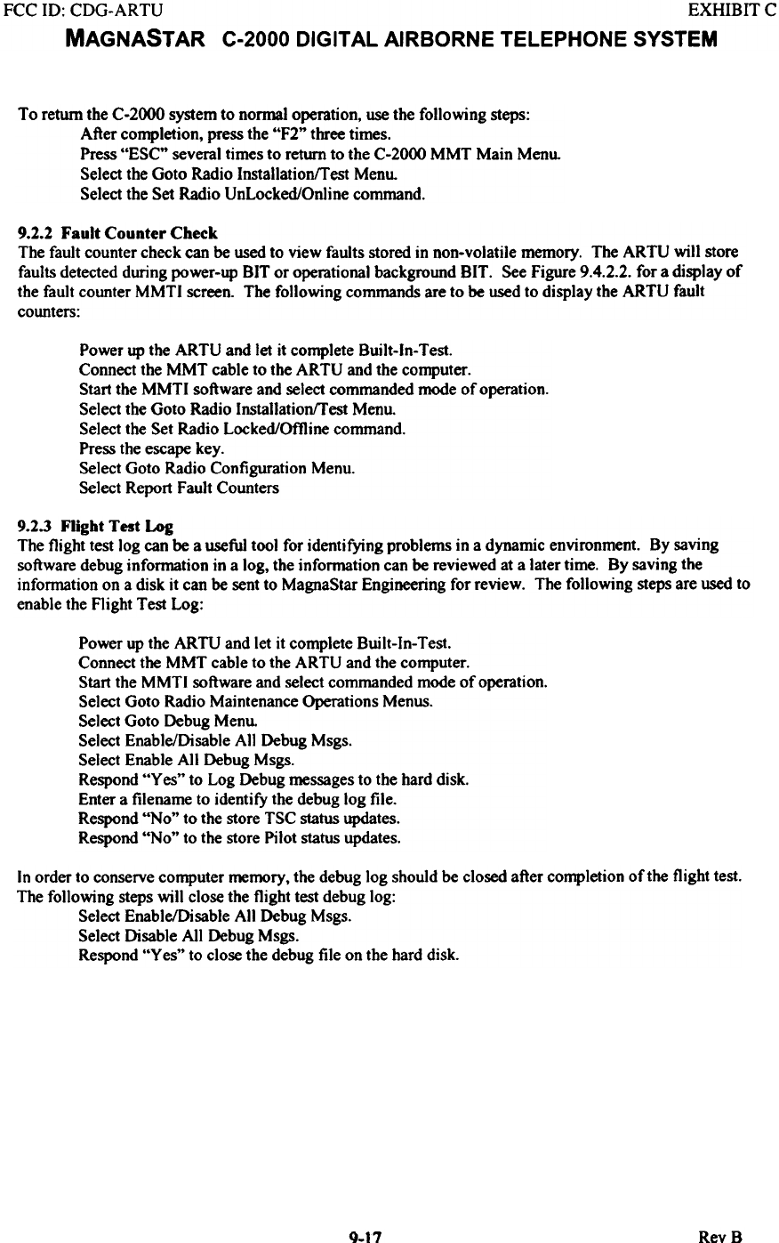
To return the C-2000 system to nonnal operation, use the following steps:
After completion, press the "F2" three times.
Press "ESC" several times to return to the C-2000 MMT Main Menu.
Select the Goto Radio lnstallarion!r est Menu.
Select the Set Radio Unlocked/Online command.
9.2.2 Fault Counter Check
The fault counter check can be used to view faults stored in non-volatile memory. The ARTU will store
faults detected during power-up BIT or operational background BIT. See Figure 9.4.2.2. for a display of
the fault counter MMTI screen. The following commands are to be used to display the ARTU fault
counters:
Power up the ARTU and let it complete Built-ln- Test.
Connect the MMT cable to the ARTU and the computer.
Start the MMTI software and select commanded mode of operation.
Select the Goto Radio InstallatjonfTest Menu.
Select the Set Radjo Locked/Offline command.
Press the escape key.
Select Goto Radio Configuration Menu.
Select Report Fault Counters
9.2.3 Flight Test Log
The flight test log can be a useful tool for identifying problems in a dynamic environment. By saving
software debug information in a log, the information can be reviewed at a later time. By saving the
information on a disk it can be sent to MagnaStar Engineering for review. The following steps are used to
enable the Flight Test Log:
Power up the ARTU and let it complete Built-In-Test.
Connect the MMT cable to the ARTU and the computer.
Start the MMTI software and select commanded mode of operation.
Select Goto Radio Maintenance Operations Menus.
Select Goto Debug Menu.
Select Enable/Disable All Debug Msgs.
Select Enable All Debug Msgs.
Respond "Yes" to Log Debug messages to the hard disk.
Enter a filename to identify the debug log file.
Respond "No" to the store TSC Status updates.
Respond "No" to the store Pilot Status updates.
In order to conserve computer memory, the debug log should be closed after completion of the flight test.
The following steps will close the flight test debug log:
Select Enable/Disable All Debug Msgs.
Select Disable All Debug Msgs.
Respond "Ves" to close the debug file on the hard disk.
RevBQ.t7
FCC ID: CDG-ARTU EXHIBIT C
MAGNASTAR C-2000 DIGITAL AIRBORNE TELEPHONE SYSTEM
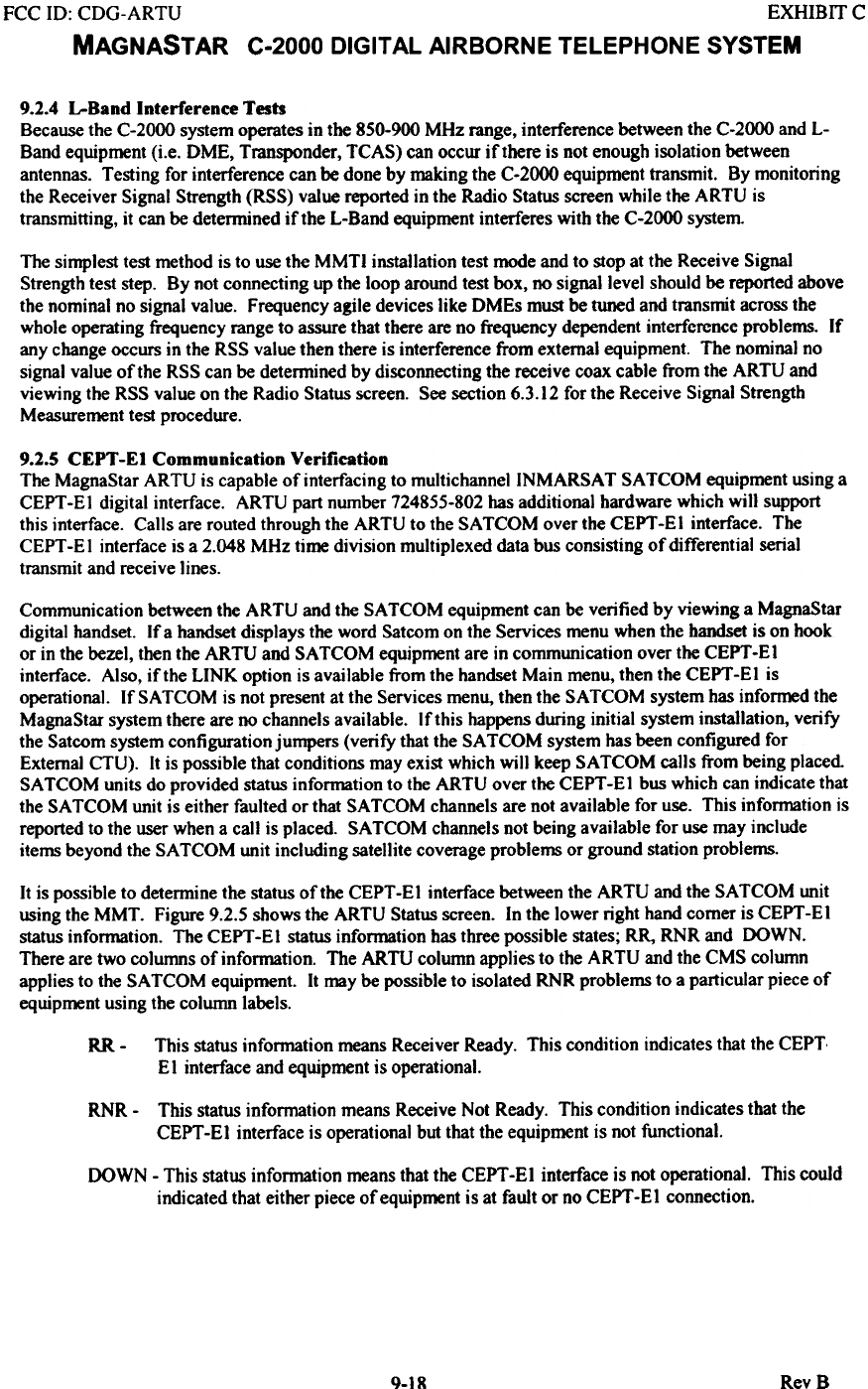
9.2.4 L-Band Interference Tests
Because the C-2000 system operates in the 850.900 MHz range, interference between the C.2000 and L-
Band equipment (i.e. DME, Transponder, TCAS) can occur if there is not enough isolation between
antennas. Testing for interference can be done by making the C-2000 equipment transmit. By monitoring
the Receiver Signal Strength (RSS) value reported in the Radio Status screen while the ARTU is
transmitting, it can be determined if the L-Band equipment interferes with the C-2000 system.
The simplest test method is to use the MMTI installation test mode and to stop at the Receive Signal
Strength test step. By not connecting up the loop around test box, no signal level should be reported above
the nominal no signal value. Frequency agile devices like DMEs must be tuned and transmit across the
whole operating frequency range to assure that there are no frequency dependent interference problems. If
any change occurs in the RSS value then there is interference from external equipment. The nominal no
signal value of the RSS can be determined by disconnecting the receive coax cable from the ARTU and
viewing the RSS value on the Radio Status screen. See section 6.3.12 for the Receive Signal Strength
Measurement test procedure.
9.2.5 CEPT -El Communication Verification
The MagnaStar ARTU is capable of interfacing to multichannellNMARSA T SA TCOM equipment using a
CEPT -EI digital interface. ARTU part number 724855-802 has additional hardware which will support
this interface. Calls are routed through the ARTU to the SA TCOM over the CEPT -E I interface. The
CEPT -E I interface is a 2.048 MHz time division multiplexed data bus consisting of differential serial
transmit and receive lines.
Communication between the ARTU and the SA TCOM equipment can be verified by viewing a MagnaStar
digital handset. If a handset displays the word Satcom on the Services menu when the handset is on hook.
or in the bezel, then the ARTU and SA TCOM equipment are in communication over the CEPT -E I
interface. Also, if the LINK option is available from the handset Main menu, then the CEPT-EI is
operational. If SA TCOM is not present at the Services menu, then the SA TCOM system has informed the
MagnaStar system there are no channels available. If this happens during initial system installation, verify
the Satcom system configuration jumpers (verify that the SA TCOM system has been configured for
External CTU). It is possible that conditions may exist which will keep SA TCOM calls from being placed
SA TCOM units do provided status information to the ARTU over the CEPT -E I bus which can indicate that
the SA TCOM unit is either faulted or that SA TCOM channels are not available for use. This information is
reported to the user when a call is placed. SA TCOM channels not being available for use may include
items beyond the SA TCOM unit including satellite coverage problems or ground station problems.
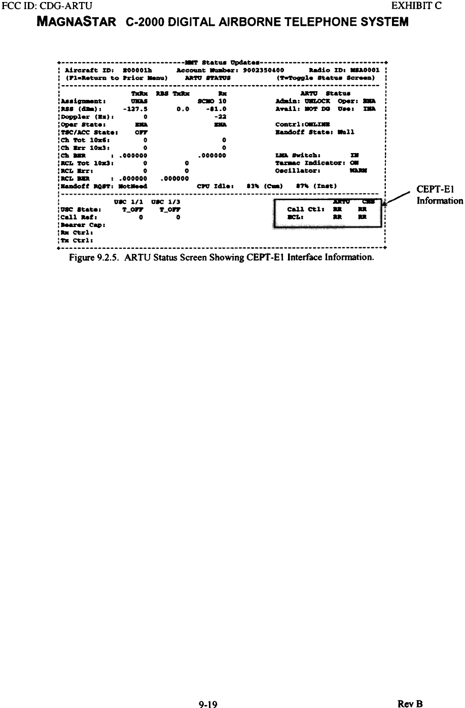
It is possible to detennine the status of the CEPT -EI interface between the ARTU and the SATCOM unit
using the MMT. Figure 9.2.5 shows the ARTU Status screen. In the lower right hand comer is CEPT -EI
status information. The CEPT -EI status information has three possible states; RR, RNR and DOWN.
There are two columns of information. The ARTU column applies to the ARTU and the CMS column
applies to the SA TCOM equipment. It may be possible to isolated RNR problems to a particular piece of
equipment using the column labels.
This status infom1ation means Receiver Ready. This condition indicates that the CEPT.
El interface and equipment is operational.
RR-
RNR - This status information means Receive Not Ready. This condition indicates that the
CEPT -E 1 interface is operational but that the equipment is not functional.
DOWN - This status information means that the CEPT -El interface is not operational. This could
indicated that either piece of equipment is at fault or no CEPT -E 1 connection.
RevSQ.IK
FCC ID: CDG-ARTU EXHIBIT C
MAGNASTAR C-2000 DIGITAL AIRBORNE TELEPHONE SYSTEM
+ at.atu. up.sat +
: Aizeraft ID: 800001h AcCOUDt 8a8b8r: '002350600 -.4io ID. 88&0001 :
: CP1...tUrD to Prior """) U'lV ftA~ C~l. at..tu. S~) :
: :
: - ... -.. U'lV at.atu. :
:aa.iv-at. - ~ 10 Ad8iA: U8LOCK 0DeZ"" :
:..S C488). -127.5 0.0 -81.0 ATa!l: .or DO v... ~ :
:Doppl.Z' CB.). 0 -22 :
:Opezo Stat .. CODt.%'l.~Ia :
:T8C/ACC Stat.. OFF 8aD4o11 Stat.. .-11 :
:Ch Yot lOx6. 0 0 :
: Ch 8Z'Z' 1 0..3 . 0 0 :
:Ch ... . .000000 .000000 ~ SWitch. I8 :
:acL Yot 10..3. 0 0 ".- ID4ioat_. ~ :
:.cL 8Z'Z'. 0 0 Oacill-tor :
:acL ... : .000000 .000000 :
:8aD4011 aQ8'f: 8ot.-.e4 CPO 141.. 83- CC-) an CIaat.) ! CEPT-EI
' ,
: VIC 1/1 V8C 1/3 Inforn1ation
:V8C Stat.. "_On' "_OFF caU croll
:Cal1..,. 0 0 8CL.
: -- Cap:
:.. Ct.%' 1 . ,
: 'fa Ct.%' 1 . :
+ +
Figure 9.2.5. ARTU Status Screen Showing CEPT -EI Interface Infonnation.
RevB
9-19
FCC 10: CDG-ARTU EXHffilT C
MAGNASTAR C-2000 DIGITAL AIRBORNE TELEPHONE SYSTEM
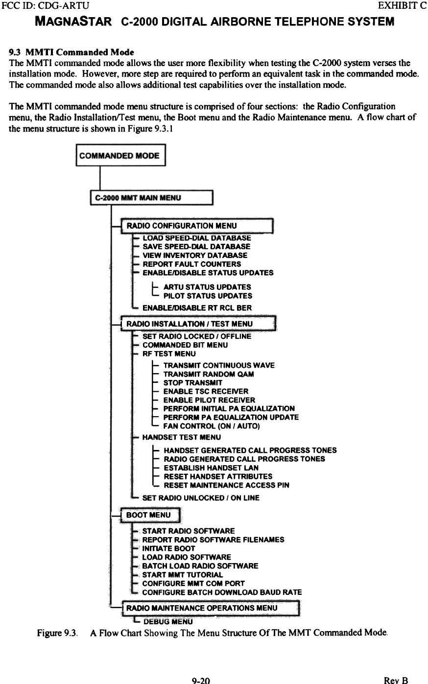
9.3 MMTI Commanded Mode
The MMTl commanded mode allows the user more flexibility when testing the C-2000 system verses the
installation mode. However, more step are required to perform an equivalent task in the commanded mode.
The commanded mode also allows additional test capabilities over the installation mode.
The MMTI commanded mode menu structure is comprised of four sections: the Radio Configuration
menu, the Radio Installation/Test menu, the Boot menu and the Radio Maintenance menu. A flow chart of
the menu structure is shown in Figure 9.3.1
~ RADIO CONFIGURATION MENU
LOAD SPEED-DIAL DATABASE
SAVE SPEED-DIAL DATABASE
VIEW INVENTORY DATABASE
REPORT FAULT COUNTERS
ENABLE/DISABLE STATUS UPDATES
t: ARTU STATUS UPDATES
PILOT STATUS UPDATES
ENABLE/DISABLE RT RCL BER
-I RADIO INSTALLATION I TEST MENU
SET RADIO LOCKED I OFFLINE
COMMANDED BIT MENU
RF TEST MENU
TRANSMIT CONTINUOUS WAVE
TRANSMIT RANDOM QAM
STOP TRANSMIT
ENABLE TSC RECEIVER
ENABLE PILOT RECEIVER
PERFORM INITIAL PA EQUALIZATION
PERFORM PA EQUALIZATION UPDATE
FAN CONTROL (ON I AUTO)
HANDSET TEST MENU
~HANDSET GENERATED CALL PROGRESS TONES
RADIO GENERATED CALL PROGRESS TONES
EST ABUSH HANDSET LAN
RESET HANDSET ATTRIBUTES
RESET MAINTENANCE ACCESS PIN
SET RADIO UNLOCKED I ON LINE
1--1 BOOT MENU
START RADIO SOFTWARE
REPORT RADIO SOF1WARE FILENAMES
INITIATE BOOT
LOAD RADIO SOF1WARE
BATCH LOAD RADIO SOFTWARE
START MMT TUTORIAL
CONFIGURE MMT COM PORT
CONFIGURE BATCH DOWNLOAD BAUD RATE
'--I RADIO MAINTENANCE OPERATIONS MENU
DEBUG MENU
A Flow Chart Showing The Menu Structure Of The MMT Commanded Mode.
Figure 9.3.
RevB9-20
FCC ill: CDG-ARTU EXHIBIT C
MAGNASTAR C-2000 DIGITAL AIRBORNE TELEPHONE SYSTEM
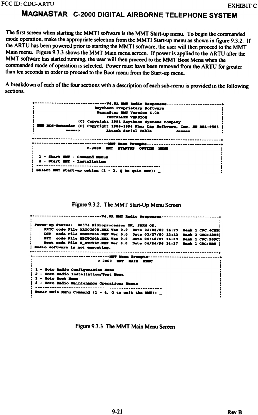
The first screen when starting the MMTI software is the MMT Start-up menu. To begin the conDnanded
mode operation, make the appropriate selection from the MMTI Start-up menu as shown in figure 9.3.2. If
the ARTU has been powered prior to starting the MMTI software. the user will then proceed to the MMT
Main menu. Figure 9.3.3 shows the MMT Main menu screen. If power is applied to the ARTU after the
MMT software has started running, the user will then proceed to the MMT Boot Menu when the
CODm1anded mode of operation is selected. Power must have been feDX)ved from the ARTU for greater
than ten seconds in order to proceed to the Boot menu from the Start-up menu.
A breakdown of each oftbe four sections with a description of each sub-~u is provided in the following
sections.
+ V'.OA ~ -.4io "8P0D8e +
: ~ Propzoietaryo 8of~ :
: ,..tar 87 v_.iOG '.0& :
: IU'rALL8a VDBI~ :
: (C) Copyright 1'" aQtlaeOD .,..t- C-. :
I - er (C) CGpJ'Z'ight 1"'-1'" PIaar ~ 8of~. X-. - 81,-'503 :
: > Wt~h aerial Cable < :
+ +
+ r ~ +
: C-3000 -.r ~ 0ftZ~ - :
: I
: 1 - 8t.an -.r - C-.a4 _. :
I 3 - 8t.&&'t. -.r - I_t.a11at.~ :
I I
I ,
: 881ect. -.r .t.aft-~ ~ioa C 1 - 3. 0 too ~it. -.r) I - I
Figure 9.3.2. The MMT Start-Up Menu Screen
+ V'.OA ~ 884io " +
, ,
, ,
: ~-ap 8taC... 80378 Kicroproc...or OK. 8aAK OK. :
: Aa'fC 0048 rile Aa'fCC'08.8D Vezo 0.0 DeC. 0'/08/00 1,.25 88M 1 cac.f.CD:
: ~ code rile ~'0A.8D Vezo 0.0 DeC. 03/27/00 12.13 88M 2 cac.12'8:
: arr ood8 rile KarrC'OA.8D Vezo 0.0 DeC. 05/18/" 18.03 88M 1 C8Cs20ee:
: 8ooC ood8 ril. ML-.cJ1C.8D Var 0.0 DeC8 0'/2'1'8 1,.27 88M 1 C8Cs'" :
: 884io -'~ i. - _ciag.
+ +
~ .~ : C-2000 ~ DX8 - :
, ,
, .
: 1 - ~ 88dio CODfigazo.ci- - :
: 2 - ~ 884io XA8C&11aCi-"_c - :
:J-~8ooC- :
: , - _0 88dio *iAt:--. aperati-. -- :
: :
: 8DCezo Kai. - C-- (1 - '. 0 to q,.it t.Joe ~). - I
I I
Figure 9.3.3 The MMT Main Menu Screen.
9-21 RevB
FCC ID: CDG-ARTU EXHIBIT C
MAGNAST AR C-2000 DIGITAL AIRBORNE TELEPHONE SYSTEM
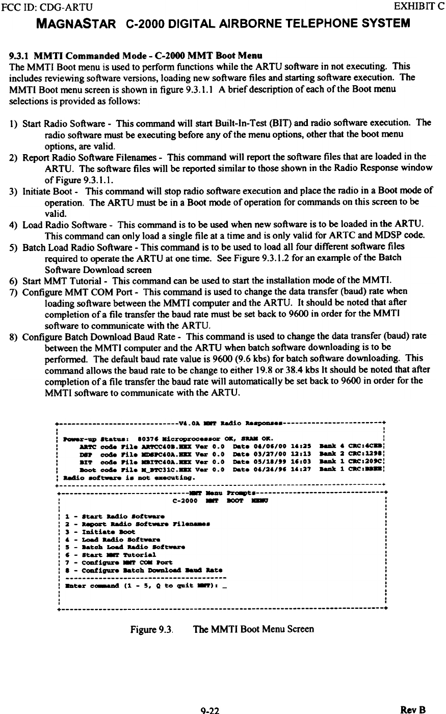
9.3.1 MMTI Commanded Mode - C-2000 MMT Boot Menu
The MMTI Boot menu is used to perfonn functions while the ARTU software in not executing. This
includes reviewing software versions, loading new software files and starting software execution. The
MMTI Boot menu screen is shown in figure 9.3. I. I A brief description of each of the Boot menu
selections is provided as follows:
I} Start Radio Software - This command will start Built-In-Test (BIT) and radio software execution. The
radio software must be executing before any of the menu options, other that the boot menu
options, are valid.
2} Report Radio Software Filenames - This command will report the software files that are loaded in the
ARTU. The software files will be reported similar to those shown in the Radio Response window
of Figure 9.3.1.1.
3} Initiate Boot - This command will stop radio software execution and place the radio in a Boot mode of
operation. The ARTU must be in a Boot mode of operation for commands on this screen to be
valid.
4} Load Radio Software - This command is to be used when new software is to be loaded in the ARTU.
This command can only load a single file at a time and is only valid for ARTC and MDSP code.
5} Batch Load Radio Software - This command is to be used to load all four different software files
required to operate the ARTU at one time. See Figure 9.3.1.2 for an example of the Batch
Software Download screen
6} Start MMT Tutorial- This command can be used to start the installation mode of the MMTI.
7} Configure MMT COM Port - This command is used to change the data transfer (baud) rate when
loading software between the MMTI computer and the ARTU. It should be noted that after
completion of a file transfer the baud rate must be set back to 9600 in order for the MMTI
software to communicate with the ARTU.
8} Configure Batch Download Baud Rate - This command is used to change the data transfer (baud) rate
between the MMTI computer and the ARTU when batch software downloading is to be
performed. The default baud rate value is 9600 (9.6 kbs) for batch software downloading. This
command allows the baud rate to be change to either 19.8 or 38.4 kbs It should be noted that after
completion of a file transfer the baud rate will automatically be set back to 9600 in order for the
MMTI software to communicate with the ARTU.
+ V6.0A -.r aadio "~e +
. .
. .
: ~~-ap .~a~.o 10376 .ic~oproce.8Or OK. SRA8 OK. :
: Aa~ coda rile ~60..B8X V~ 0.0 Da~e 0./06/00 ~.025 8aDk 6 c.cotc..:
: DS. coda rile 8D8.c.OA.B8X V~ 0.0 Date 03/27/00 12013 8aDk 2 c.c012'1:
: .r~ coda Pile ..r~.OA.B8X V~ 0.0 Da~e 05/11/" 16.03 8aDk 1 c.c.20'C:
: - coda rile --.~31C.B8X V~ 0.0 Date 0./2./'6 ~..27 8aDk 1 c.c.-:
: 88410 .of~ i. DOt -_t1ng.
+ +
+ -.. ~e +
: C-2000 - BOO!' - :
I .
. .
: 1 - start. b4io 8oftware :
: 2 - ~ Radio SOft-- ril_. :
: 3 - rDi~iat.e - :
: . - LO84 aadio SOf~ :
: 5 - Ba~cb LO84 b4io SOf~ :
: 6 - start. - fttorial :
: 7 - c~igure - ~ .~ :
: 1 - c~igure Batcb ~~ ..a4 aate :
: :
:8Dterc~(1-5.Qtoquit_).- :
. I
. I
. I
. .
+ +
The MMTI Boot Menu Screen
Figure 9.3.
Rev 8
Q.22
FCC ill: CDG-ARTU EXHIBIT C
MAGNASTAR C-2000 DIGITAL AIRBORNE TELEPHONE SYSTEM
'--V'.OA.-r Radio ..~ +
. I
I I
I I
I I
. I
I I
+ +
+ r 8aDD ~ +
: C-2000 -.r .- -- ~~~~ - :
I I
I I
: bur - - fil- into the queue . ~.~ . :
: bt.r P%L B8X file to a-l0a4 f~ C:\~ (88C to q8it): ~.B8X :
I .
I .
: bter - Di_.tic an fil- into tba QU"'. . -~.~ . :
: bter P%L8DD.8D file to a-l0a4 f~ C:\~ (88C to QUit): ~.B8X :
I I
I I
: bter - appliceti- fil- tatoo tM QU"'. . U'fCc-.~ . :
: 8ater P%L B8X file to a-l0a4 f~ C:\~ (8- to QUit): ~.B8X :
I I
I I
: ...ter - »8. fil.- into the QU"'. . .u..c-.B8X . :
: ...ter P%L B8X file to a-l0a4 f~ C:\~ (88C to QUit): _pc.-.B8X :
Figure 9.3.1.2. The MMTI Batch Software Download Menu Screen
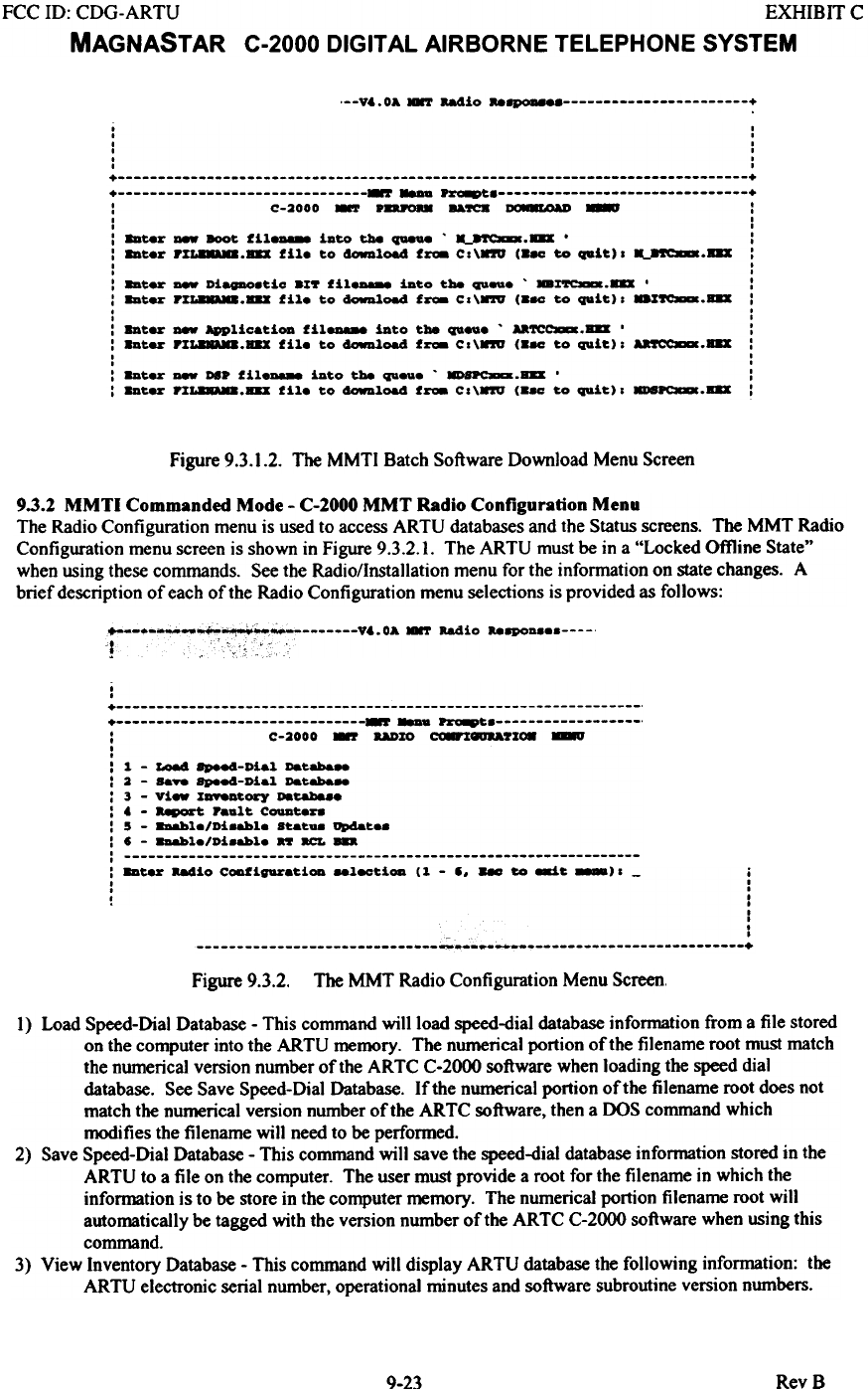
9.3.2 MMTI Commanded Mode - C-2000 MMT Radio Configuration Menu
The Radio Configuration menu is used to access ARTU databases and the Status screens. The MMT Radio
Configuration menu screen is shown in Figure 9.3.2.1. The ARTU must be in a "Locked Offline State"
when using these commands. See the Radio/lnstallation menu for the information on state changes. A
brief description of each of the Radio Configuration menu selections is provided as follows:
~--~-~"~~~ V,.OA .-r Radio "8POD ., C,
, ; ',,': 0':,'
I
I
+ + -. ~ : C-2000 - aADZO ~_7ZC8 ~
I
I
: 1 - Lo84 8pee4-Dial Databa-
: 2 - sa.. apee4-Dial Databa-
: 3 - vi- Z_tO&'Y Databa..
: . - ~ Paut COIIDt.8~.
: 5 - 8DAbl./Di.abl. 8t.tU8 ap4at..
: , - 8DAbl./Di.abl. n 8CL -
, ,
: 8Dt- a84io C-'ipratiOG _l8CtiOG (1 - I. -- ~ ~t -). - i
. I
. I
, I
. I
I
,
.
~ .
~ ~ +
Figure 9.3.2. The MMT Radio Configuration Menu Screen.
I) Load Speed-Dial Database - This command will load speed-dial database information from a file stored
on the computer into the ARTU memory. The numerical portion of the filename root must match
the numerical version number of the ARTC C-2000 software when loading the speed dial
database. See Save Speed-Dial Database. If the numerical portion of the filename root does not
match the numerical version number of the ARTC software, then a DOS command which
modifies the filename will need to be performed.
2) Save Speed-Dial Database - This command will save the speed-dial database information stored in the
ARTU to a file on the computer. The user must provide a root for the filename in which the
information is to be store in the computer memory. The numerical portion filename root will
automatically be tagged with the version number of the ARTC C-2000 software when using this
command.
3) View Inventory Database - This command will display ARTU database the following information: the
ARTU electronic serial number, operational minutes and software subroutine version numbers.
9-23 RevB
FCC 10: CDG-ARTU EXHIBIT C
MAGNASTAR C-2000 DIGITAL AIRBORNE TELEPHONE SYSTEM
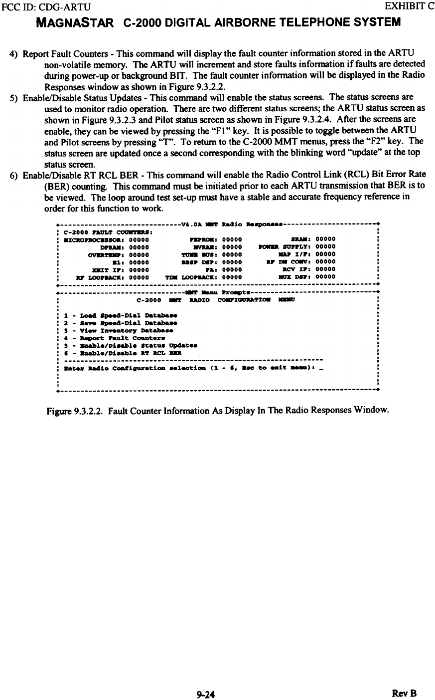
4) Report Fault Counters - This command will display the fault counter information stored in the ARTU
non-volatile memory. The ARTU will increment and store faults information if faults are detected
during power-up or background BIT. The fault counter information will be displayed in the Radio
Responses window as shown in Figure 9.3.2.2.
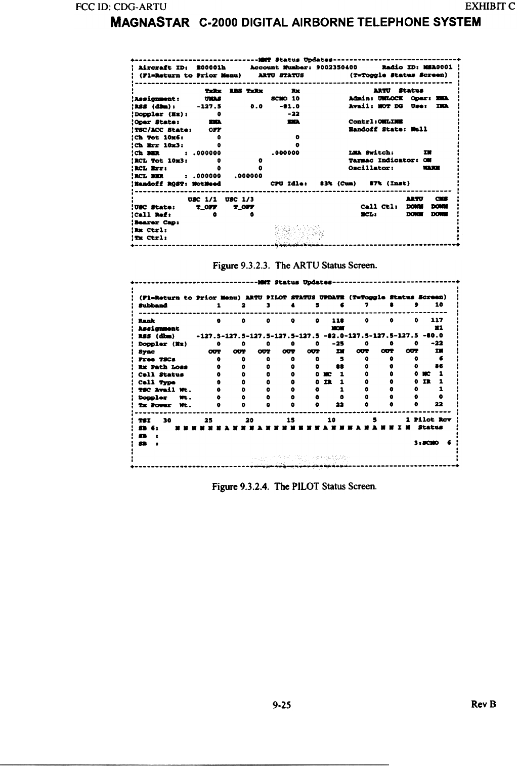
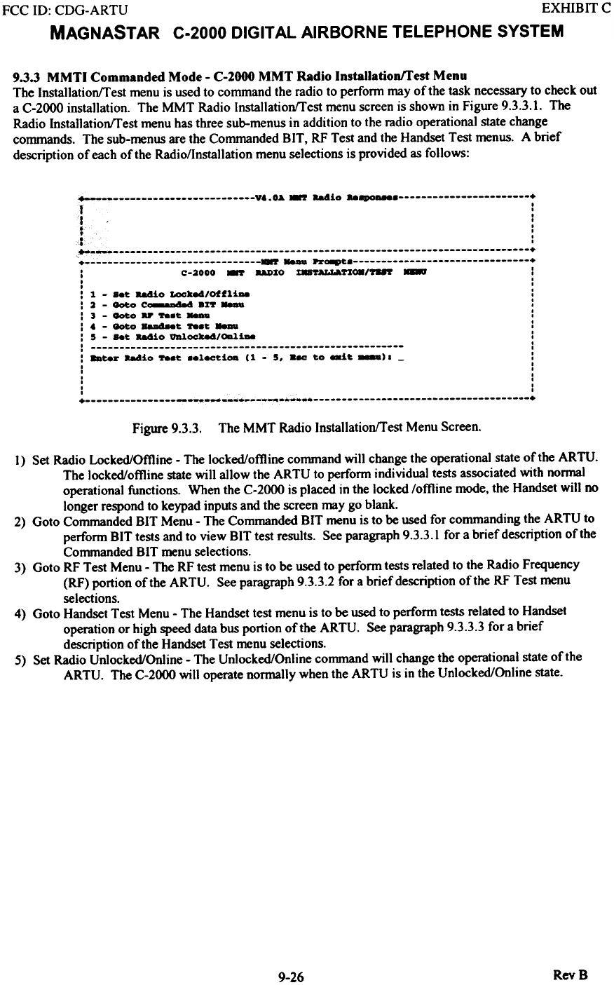
5) Enable/Disable Status Updates - This command will enable the status screens. The status screens are
used to monitor radio operation. There are two different status screens; the ARTU status screen as
shown in Figure 9.3.2.3 and Pilot status screen as shown in Figure 9.3.2.4. After the screens are
enable, they can be viewed by pressing the "FI" key. It is possible to toggle between the ARTU
and Pilot screens by pressing "T". To return to the C-2000 MMT menus, press the "F2" key. The
status screen are updated once a second corresponding with the blinking word "update" at the top
status screen.
6) Enable/Disable RT RCL BER - This command will enable the Radio Control Link (RCL) Bit Error Rate
(BER) counting. This command must be initiated prior to each ARTU transmission that BER is to
be viewed. The loop around test set-up must have a stable and accurate frequency reference in
order for this function to work.
+ V&.OA -.r Radio Reep0a8e +
: C-2000 nUL'r COUftD8: :
: mcao..oc.saoa: 00000 nP_, 00000 sag: 00000 :
: DPaM' 00000 8YaAK: 00000 -- BOPPLY: 00000 :
: ova_, 00000 'IUD MJ8: 00000 UP lIP' 00000 :
: 81, 00000 "SP DSP, 00000 ar ~ CO8V, 00000 :
: X8IT IP, 00000 PA: 00000 acv IF: 00000 :
: ar LOOP..cx, 00000 ~ LOOP..cK: 00000 .ox DSP' 00000 :
+ +
+ 8T _a Pr"-t +
: C-2000 8T aADIO CO8PI_TI~ - :
, '
, .
: 1 - ~ 8p.-4-Diel Dat8b8.- :
: 2 - - 8p884-Dial Dat~ :
: 3 - vi- I_tory Databa8e :
: & - ~ halt C~t8r. :
: 5 - 8D&ble/Di8&ble Statu. update. :
: I - 8D&ble/Di8&ble aT acL ... I
: :
: 8Dter aa4io Ccmfiga&-ati- _l~i- (1 - I. -- to ~t -). - :
, '
, .
, .
, '
+ +
Figme 9.3.2.2. Fault Counter Infonnation As Display In The Radio Responses Window.
RevB
9-24
FCC ill: CDG-ARTU EXHIBIT C
MAGNASTAR C-2000 DIGITAL AIRBORNE TELEPHONE SYSTEM
+ r Statu. ap4at +
: Aircx.1t %D. 800001b Accouat ~s '002350'00 aa4io %D: .-&0001 :
: (Pl...t-. to .ri- -) - ftA~S ('r-'rOftl. Stat- &cr.-) :
: :
: - US - Roc u~ Stat- :
: i_t. - ~ 10 Adain: ~ Oper' ~ :
:..S (488): -127.5 0.0 -81.0 A.ai1: 8Or DG v... %8a :
: Dopp1.r (Sa): 0 -22 :
:Oper Stat.: ~ ~ CODtr1so.L%88 :
:TSC/ACC Stat.s OFF BaDdoff Stat.: ..11 :
:Cb 'rot lOx6: 0 0 :
:Cb 8&'r 10.3: 0 0 :
:Cb ... : .000000 .000000 ~ switch: %8 I
I~L 'rot 10x3. 0 0 Taswac %D4icat_: ~ :
:~L 8&'r: 0 0 O.ci11at_: I
I~'" : .000000 .000000 :
:Baadoff aQ8T: ~ c.u %41.: 83' (CWa) ~ (%..~) :
: :
: vsc 1/1 U8C 1/3 U'fU C88 :
lusc Stat.: 'f-opr 'f-opr call ~1. ~ ~ :
: call ..f. 0 0 8CL. ~ ~ I
'Bearer cap. :
:. :-. C . '. .
," ~r1. ,'. c .
'"' ."fa ~r1. ,
~ ~~~~ ~
Figure 9.3.2.3. The ARTU Status Screen.
+ r Statu. update +
, ,
, ,
: (,.l...t-. to ~ior -) UW .I~ &'raWS _B (~le ftatua SO_) :
:hbb8D4 1 2 3 , 5 , 7 I , 10 :
: :
: RaM 0 0 0 0 0 111 0 0 0 117 :
: ...i.-t - Bl :
: us (418) -127.5-127.5-127.5-127.5-127.5 -12.0-127.5-127.5-127.5 -10.0 :
: Dopplar (B.) 0 0 0 0 0 -25 0 0 0 -22 :
: Syac oor oor oor oor oor IB oor ~ oor IB :
: Free ~C. 0 0 0 0 0 5 0 0 0 ':
: .. .atb Lo.. 0 0 0 0 0 II 0 0 0 I' :
: Call Statu. 0 0 0 0 0 ~ 1 0 0 0 ~ 1 :
: Cell ~ 0 0 0 0 0 x. 1 0 0 0 x. 1 :
: ~8C Awail Wt. 0 0 0 0 0 1 0 0 0 1:
: Dopplar Wt. 0 0 0 0 0 0 0 0 0 0 :
: ~ ~ Wt. 0 0 0 0 0 22 0 0 0 22 :
: :
: ~SI 30 25 20 15 10 5 1 .ilot acY :
: .. ,. B B . B B B A B . B A . B B B . . . A . . . A . A . . I. Statua :
:.. . :
:.. . 3.~ ':
, ,
, ,
, c'
, ,
+ ~-~~~ ~ +
Figure 9.3.2.4. The PILOT Status Screen.
RevB
9-25
FCC ID: CDG-ARTU EXHIBIT C
MAGNASTAR C-2000 DIGITAL AIRBORNE TELEPHONE SYSTEM
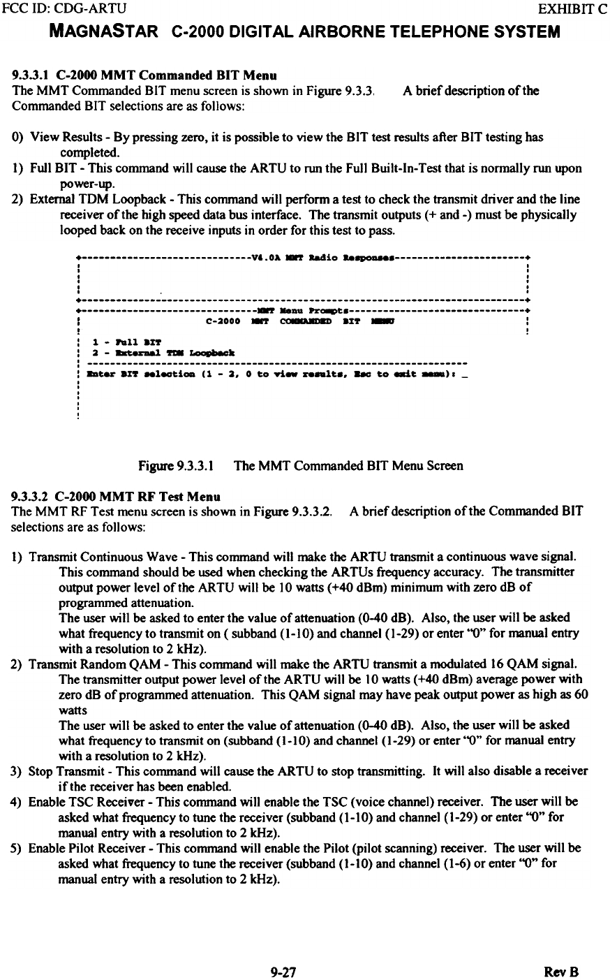
9.3.3 MMTI Commanded Mode - C-2000 MMT Radio Installationffest Menu
The Installationffest menu is used to command the radio to perfonn may of the task necessary to check out
a C-2000 installation. The MMT Radio Installationffest menu screen is shown in Figure 9.3.3.1. The
Radio Installationffest menu has three sub-menus in addition to the radio operational state change
commands. The sub-menus are the Commanded BIT. RF Test and the Handset Test menus. A brief
description of each of the Radio/lnstallation menu selections is provided as follows:
~ y. .0& -.7 aadio "8P0D888 +
f I
.
1 :
. I
.. .
. .
~ .
~ +
'+ 87 - ~~ +
: C-2000 -.7 UDIO I8~n~/"'" - :
I .
I .
: ~ - ..~ aa4io Loc-.4/OffliAe :
: 2 - ~o C_--"-" .z~ - :
:J-~oUft.~- :
: . - ~o ~~ ft.~ ..- :
: 5 - ..~ aa4io VDl~/ODli- :
: :
: 8Dte~ -.dio ft.~ ..18C~iOD (~ - 5. .aa ~o exi~ >. - :
. .
. .
. .
. .
. .
. .
+ ~ ~~.* +
The MMT Radio InstallationITest Menu Screen.
Figure 9.3.3.
1) Set Radio Locked/Offline - The locked/offline command will change the operational state of the ARTU.
The locked/offline state will allow the ARTU to perform individual tests associated with normal
operational functions. When the C-2000 is placed in the locked /offline mode, the Handset will no
longer respond to keypad inputs and the screen may go blank.
2) Goto Commanded BIT Menu - The Commanded BIT menu is to be used for commanding the ARTU to
perform BIT tests and to view BIT test results. See paragraph 9.3.3.1 for a brief description of the
Commanded BIT menu selections.
3) Goto RF Test Menu - The RF test menu is to be used to perform tests related to the Radio Frequency
(RF) portion of the ARTU. See paragraph 9.3.3.2 for a brief description of the RF Test menu
selections.
4) Goto Handset Test Menu - The Handset test menu is to be used to perform tests related to Handset
operation or high speed data bus portion of the ARTU. See paragraph 9.3.3.3 for a brief
description of the Handset Test menu selections.
5) Set Radio Unlocked/Online - The Unlocked/Online command will change the operational state of the
ARTU. The C-2000 will operate normally when the ARTU is in the Unlocked/Online State.
RevB
9-26
FCC ID: CDG-ARTU EXHIBIT C
MAGNASTAR C-2000 DIGITAL AIRBORNE TELEPHONE SYSTEM
A brief description oftbe
9.3.3.1 C-2000 MMT Commanded BIT Menu
The MMT Commanded BIT menu screen is shown in Figure 9.3.3,
Commanded BIT selections are as follows:
0) View Results - By pressing zero, it is possible to view the BIT test results after BIT testing has
completed.
I) Full BIT - This command will cause the ARTU to run the Full Built-In-Test that is nonnally run upon
power-up.
2) External TDM Loopback - This command will perform a test to check the transmit driver and the line
receiver of the high speed data bus interface. The transmit outputs (+ and -) must be physically
looped back on the receive inputs in order for this test to pass.
+ V&.OA ~ R84io ..~ +
. I
. I
. .
. .
. .
. .
+ +
+ ~ -.au ~ +
I C-2000 .., ~~ .%~ - :
t !
: 1 - ..11 ax"
: 2 - -~ .,. roo.-k
: : 8Bt.- ax" _l_t.i- (1 - 2. 0 t.o ri- ...~t." - t.o ~t. _)1 -
I
I
I
I
,
,
!
Figme 9.3.3.1 The MMT Commanded BIT Menu Screen
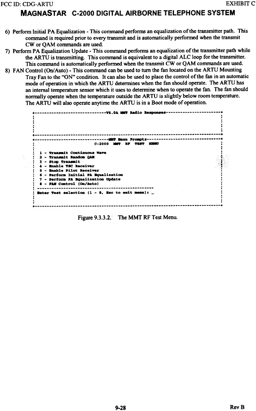
9.3.3.2 C-2000 MMT RF Test Menu
The MMT RF Test menu screen is shown in Figure 9.3.3.2.
selections are as fo\lows:
A brief description of the Commanded BIT
1) Transmit Continuous Wave - This command will make the ARTU transmit a continuous wave signal.
This command should be used when checking the ARTUs frequency accuracy. The transmitter
output power level of the ARTU will be]O watts (+40 dBm) minimum with zero dB of
programmed attenuation.
The user will be asked to enter the value of attenuation (0-40 dB). Also, the user will be asked
what frequency to transmit on ( subband (1-10) and channel (1-29) or enter "0" for manual entry
with a resolution to 2 kHz).
2) Transmit Random QAM - This command will make the ARTU transmit a modulated 16 QAM signal.
The transmitter output power level of the ARTU will be ] 0 watts (+40 dBm) average power with
zero dB of programmed attenuation. This QAM signal may have peak output power as high as 60
watts
The user will be asked to enter the value of attenuation (0-40 dB). Also, the user will be asked
what frequency to transmit on (subband (]-10) and channel (]-29) or enter "0" for manual entry
with a resolution to 2 kHz).
3) Stop Transmit - This command will cause the ARTU to stop transmitting. It will also disable a receiver
if the receiver has been enabled.
4) Enable TSC Receiver - This command will enable the TSC (voice channel) receiver. The user will be
asked what frequency to tune the receiver (subband (]-]O) and channel (1-29) or enter "0" for
manual entry with a resolution to 2 kHz).
5) Enable Pilot Receiver - This command will enable the Pilot (pilot scanning) receiver. The user will be
asked what frequency to tune the receiver (subband (]-]O) and channel (1-6) or enter "0" for
manual entry with a resolution to 2 kHz).
9-27 RevS
FCC 10: CDG-ARTU EXHIBIT C
MAGNASTAR C-2000 DIGITAL AIRBORNE TELEPHONE SYSTEM
6) Perfonn Initial PA Equalization - This command perfo~ an equalization of the transmitter path. This
command is required prior to every transmit and is automatically perfonned when the transmit
CW or QAM commands are used.
7) Perfonn P A Equalization Update - This command performs an equalization of the transmitter path while
the ARTU is transmitting. This command is equivalent to a digital ALC loop for the transmitter.
This command is automatically perfonned when the transmit CW or QAM commands are used.
8) FAN Control (On/Auto) - This command can be used to turn the fan located on the ARTU Mounting
Tray Fan to the "ON" condition. It can also be used to place the control of the fan in an automatic
mode of operation in which the ARTU determines when the fan should operate. The ARTU bas
an internal temperature sensor which it uses to determine when to operate the fan. The fan should
normally operate when the temperature outside the ARTU is slightly below room temperature.
The ARTU will also operate anytime the ARTU is in a Boot mode of operation.
+ V6.0A.-r aa4io "8PQD8e8 +
: :
, .
, .
, .
, .
: I
+ +
+ ~ 8aDu ~t +
: C-2000 .-r D - - :
: :
: 1 - 'rr..-it CODtia_. -- :
: 2 - 'rr..-it ~ QAX{
I 3 - St OP ~~ tJI
I --~ '. c
I 6 - _le 'r8C _iv.r 1
: 5 - 8II8hle .i1ot ..oeiv.r r
: ,- "rfoza Initial .A 8qaali.eti~ :
: 7 - hrfoza .A 8q1I8li..tiOD update :
: 8 - r- C~trol (~/A1Ito) :
: :
: 8Dter ~.t ..lectiOD (1 - 8. ..0 to eait ). - :
, '
, '
, '
, '
+ +
The MMT RF Test Menu.
Figure 9.3.3.2.'
RevB
9-28
FCC ID: CDG-ARTU EXHIBIT C
MAGNASTAR C-2000 DIGITAL AIRBORNE TELEPHONE SYSTEM
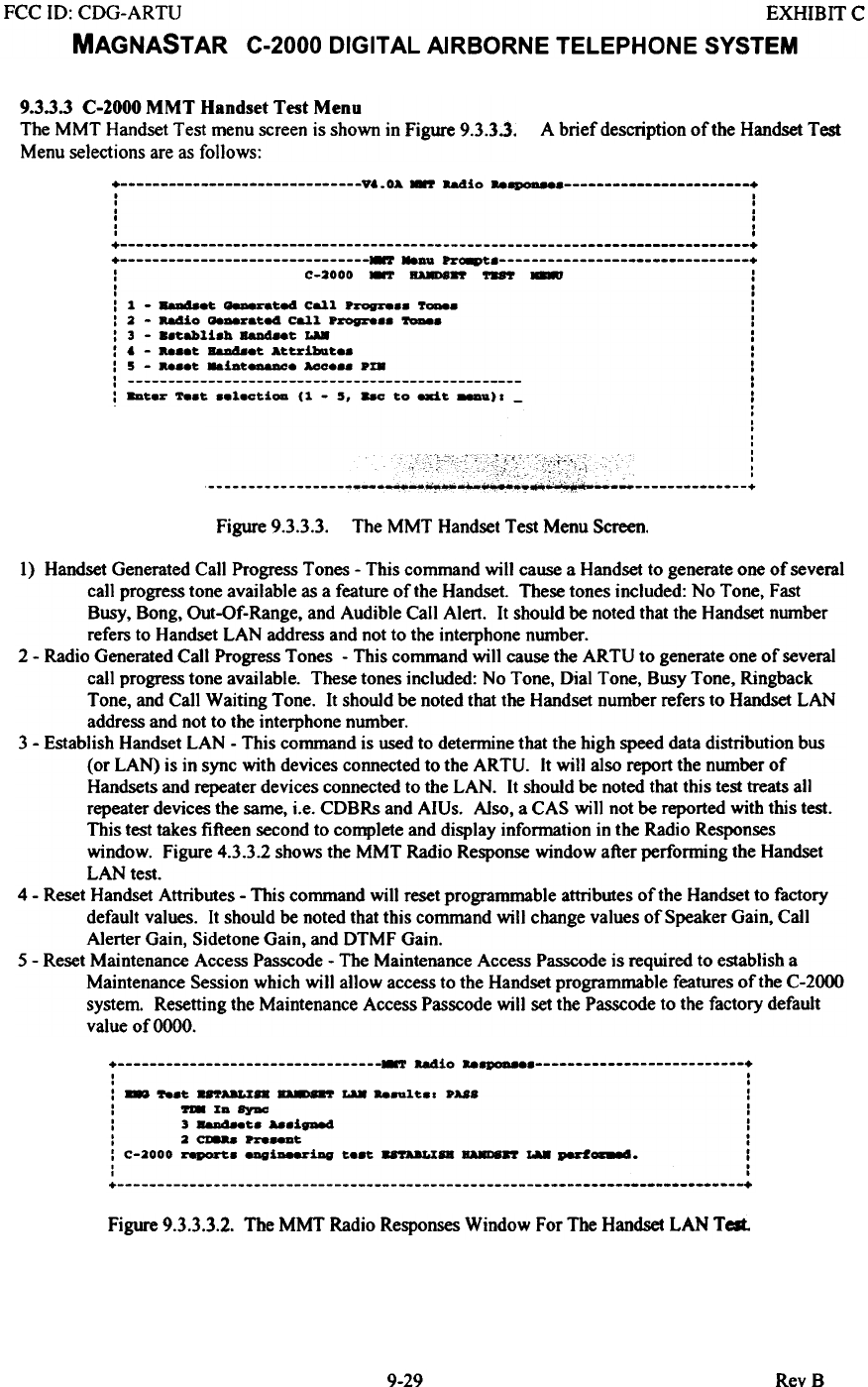
9.3.3.3 C-2000 MMT Handset Test Menu
The MMT Handset Test menu screen is shown in Figure 9.3.33.
Menu selections are as follows: A brief description of the Handset Test
+ vt. OA .-r aadio ..~ +
, ,
I f
f f
, f
f ,
I ,
+ +
+ r ~U ~O8Pt +
: C-2000 -.r BA88ft - - :
, ,
I ,
: 1 - BaD48.t -.tea Call P.-ogre.. 7-.. :
: 2 - 884io Qe-~.te4 Call P.-ogre.. -. :
: 3 - ..tabli.h 8aD4..t LA8 :
: t - t Baa48.t Att~ibat.. :
: 5 - t ..iat--. AGO... pm :
: :
: 8Dt.~ 7e.t ..l.ctioa (1 - 5. 8ac to exit 88Du) I - :
.
.
:
0
0
Figure 9.3.3.3. The MMT Handset Test Menu Screen.
1) Handset Generated Call Progress Tones - This command will cause a Handset to generate one of several
call progress tone available as a feature of the Handset. These tones included: No Tone, Fast
Busy, Bong, Out-Of-Range, and Audible Call Alert. It should be noted that the Handset number
refers to Handset LAN address and not to the interphone number.
2 - Radio Generated Call Progress Tones - This command will cause the ARTU to generate one of several
call progress tone available. These tones included: No Tone, Dial Tone, Busy Tone, Ringback
Tone, and Call Waiting Tone. It should be noted that the Handset number refers to Handset LAN
address and not to the interphone number.
3 - Establish Handset LAN - This command is used to determine that the high speed data distribution bus
(or LAN) is in sync with devices connected to the ARTU. It will also report the number of
Handsets and repeater devices connected to the LAN. It should be noted that this test treats all
repeater devices the same, i.e. CDBRs and AIUs. Also, a CAS will not be reported with this test.
This test takes fifteen second to complete and display infonnation in the Radio Responses
window. Figure 4.3.3.2 shows the MMT Radio Response window after performing the Handset
LAN test.
4 - Reset Handset Attributes - This command will reset programmable attributes of the Handset to factory
default values. It should be noted that this command will change values of Speaker Gain, Call
Alerter Gain, Sidetone Gain, and DTMF Gain.
5 - Reset Maintenance Access Passcode - The Maintenance Access Passcode is required to establish a
Maintenance Session which will allow access to the Handset programmable features of the C-2000
system. Resetting the Maintenance Access Passcode will set the Passcode to the factory default
value of 0000.
+ T &84io "8PQD8' +
I .
I .
: - 78.t. 8rrABLI8B -- LU "_lt8' PUS :
: 78 %a ~ :
: 3 8a11488t. A88ig-a I
: 2 cmaa pze_t :
: C-2000 report.8 _i-iDV t...t. ~8B _87 ~ ped0C8e4. I
I .
1 .
+ +
Figure 9.3.3.3.2. The MMT Radio Responses Window For The Handset LAN Tell
9-29 RevB
FCC ill: CDG-ARTU EXHIBIT C
MAGNASTAR C-2000 DIGITAL AIRBORNE TELEPHONE SYSTEM
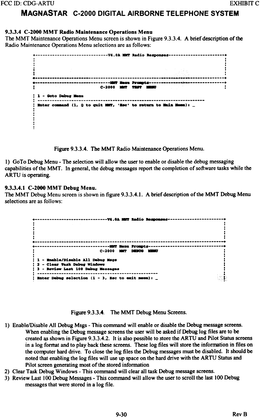
9.3.3.4 C-2000 MMT Radio Maintenance Operations Menu
The MMT Maintenance Operations Menu screen is shown in Figure 9.3.3.4. A brief description oftbe
Radio Maintenance Operations Menu selections are as follows:
+ V..OA.-r Radio Re8p0D8 +
I I
I I
I .
I .
I I
, I
I :
+ ~~~_.~ +
+ r ~ ~ +
I C-2000 -.r ~ - :
: 1 - _0 Deboag _..
: : bur c~ (1, Q to quit -, ,-, to -- to~. _)1-
I
I
I
I
I
I
I
I
I
Figure 9.3.3.4. The MMT Radio Maintenance Operations Menu.
1) GoTo Debug Menu - The selection will allow the user to enable or disable the debug messaging
capabilities of the MMT. In general, the debug messages report the completion of software tasks while the
ARTU is operating.
9.3.3.4.1 C-2000 MMT Debug Menu.
The MMT Debug Menu screen is shown in figure 9.3.3.4.1. A brief description of the MMT Debug Menu
selections are as follows:
+ V&.OA ~ 88410 "-.0-' +
I I
. I
. I
. .
I .
. .
. ,
, ,
+ +
+ ~..au ~ +
: C-2000 - ~ ~ :
I ,
I I
: 1 - 8D&bl./Ui8&bl. All Debug ..g. :
: 2 - Cl.- 'r88k Dabag WiDa-. I
: 3 - a-i- La.~ 100 Debug :
: j
: 8D~ Dabag ..l8C~iOD (1 - 3. ..0 ~o exi~ ). - ;!
Figure 9.3.3.4. The MMT Debug Menu Screens.
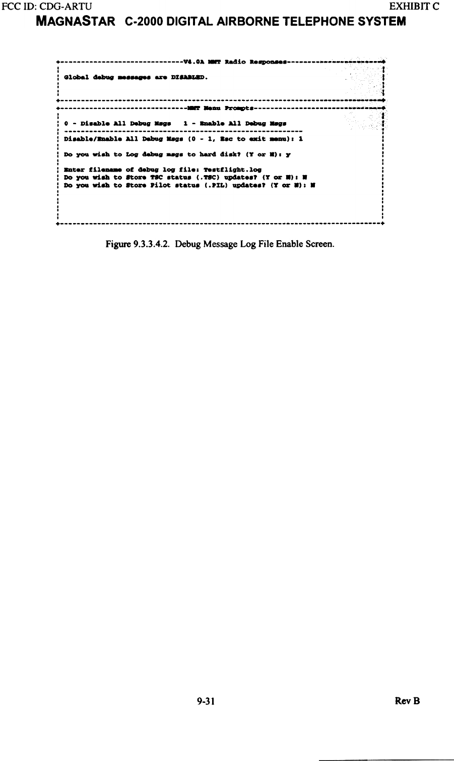
1) Enable/Disable All Debug Msgs - This command will enable or disable the Debug message screens.
When enabling the Debug message screens the user will be asked if Debug log files are to be
created as shown in Figure 9.3.3.4.2. It is also possible to store the ARTU and Pilot Status screens
in a log format and to play back these screens. These log files will store the information in files on
the computer hard drive. To close the log files the Debug messages must be disabled. It should be
noted that enabling the log files will use up space on the hard drive with the ARTU Status and
Pilot screen generating most of the stored information
2) Clear Task Debug Windows - This command will clear all task Debug message screens.
3) Review Last 100 Debug Messages - This command will allow the user to scroll the last 100 Debug
messages that were stored in a log file.
RevB
9-30
FCC ID: CDG-ARTU EXHIBIT C
MAGNAST AR C-2000 DIGITAL AIRBORNE TELEPHONE SYSTEM
+ vt. 0& ~ -.4io ..~ +
-r---
'fI
: Global d8bQV -- DI8UL8D. 1
It
: '.i
::::::::::::::::::::::::::::::::;;;-;;~-~;::::::::::::::::::::::::::::::::
'fI
: 0 - Di8abl. All D8!IQg "88 1 - ~l. All D8bag ..g. 1
: t
: Di8abl./~l. All D8!1Qg"'. (0 - 1, ..C to exit 88DD)' 1 :
I .
I .
: Do ~ ri8la to Log d8bIag to bar4 41u? (T or 8). Y I
I I
I I
: 8Dter fil8D888 of aebug log fil.. 788tflight.log :
: Do ~ ri8la to ft-. ~ 8tat.8 (. ftC) Qp48t..? (T or 8). 8 :
: Do you ri8la to Store pilot 8tat.8 (.PIL) Qp48t88? (T or 8). 8 :
I .
I I
I I
I I
I .
I I
I I
I I
+ +
Figure 9.3.3.4.2. Debug Message Log File Enable Screen.
RevB
9-31
FCC ill: CDG-ARTU EXHIBff C
MAGNASTAR C-2000 DIGITAL AIRBORNE TELEPHONE SYSTEM
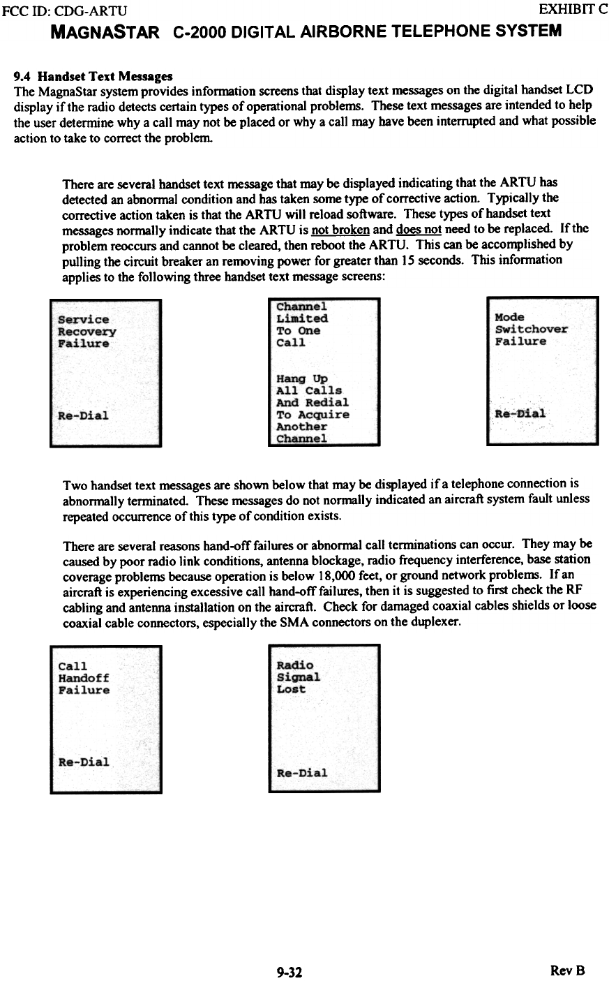
9.4 Handset Text Messages
The MagnaStar system provides infonnation screens that display text messages on the digital handset LCD
display if the radio detects certain types of operational problems. These text messages are intended to help
the user determine why a call may not be placed or why a call may have been interrupted and what possible
action to take to correct the problem
There are several handset text message that may be displayed indicating that the ARTU has
detected an abnonnal condition and has taken some type of corrective action. Typically the
corrective action taken is that the ARTU will reload software. These types of handset text
messages normally indicate that the ARTU is not broken and does not need to be replaced. If the
problem reoccurs and cannot be cleared, then reboot the ARTU. This can be accomplished by
pulling the circuit breaker an removing power for greater than IS seconds. This infonnation
applies to the following three handset text message screens:
Channel -
Limited
To One
Call
Mode
switchover
Failure
Service
Recovery
Failure
Hang Up
All Calls
And Redial
To Acquire
Another
C~~J,--
h-Dial
Re-Dial
Two handset text messages are shown below that may be displayed if a telephone connection is
abnonnally tenninated. These messages do not nonnally indicated an aircraft system fault unless
repeated occurrence of this type of condition exists.
There are several reasons hand-off failures or abnormal call tenninations can occur. They may be
caused by poor radio link conditions, antenna blockage, radio frequency interference, base station
coverage problems because operation is below 18,000 feet, or ground network proble~. If an
aircraft is experiencing excessive call hand-off failures, then it is suggested to first check the RF
cabling and antenna installation on the aircraft. Check for damaged coaxial cables shields or loose
coaxial cable connectors, especially the SMA connectors on the duplexer.
Radio
Signal
Lost
Call
Handoff
Failure
Re-Dial Re-Dial
RevB
9-32
FCC ill: CDG-ARTU EXHIBIT C
MAGNAST AR C-2000 DIGITAL AIRBORNE TELEPHONE SYSTEM
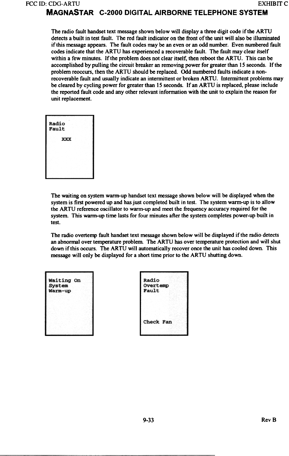
The radio fault handset text message shown below will display a three digit code if the ARTU
detects a built in test fault. The red fault indicator on the front of the unit will also be illuminated
if this message appears. The fault codes may be an even or an odd number. Even numbered fault
codes indicate that the ARTU has experienced a recoverable fault. The fault may clear itself
within a few minutes. If the problem does not clear itself, then reboot the ARTU. This can be
accomplished by pulling the circuit breaker an removing power for greater than 15 seconds. If the
problem reoccurs, then the ARTU should be replaced. Odd numbered faults indicate a non-
recoverable fault and usually indicate an intermittent or broken ARTU. Intermittent problems may
be cleared by cycling power for greater than 15 seconds. If an ARTU is replaced, please include
the reported fault code and any other relevant information with the unit to explain the reason for
unit replacement.
Radio
Fault
xxx
The waiting on system warm-up handset text message shown below will be displayed when the
system is first powered up and has just completed built in test. The system warm-up is to allow
the ARTU reference oscillator to warm-up and meet the frequency accuracy required for the
system. This warm-up time lasts for four minutes after the system completes power-up built in
test.
The radio overternp fault handset text message shown below will be displayed if the radio detects
an abnormal over temperature problem The ARTU has over temperature protection and will shut
down if this occurs. The ARTU will automatically recover once the unit has cooled down. This
message will only be displayed for a short time prior to the ARTU shutting down.
Radio
OVertemp
Fault
Waiting on
System
Warm-up
Check Fan
9-33 RevB
FCC ill: CDG-ARTU EXHIBIT C
MAGNASTAR C-2000 DIGITAL AIRBORNE TELEPHONE SYSTEM
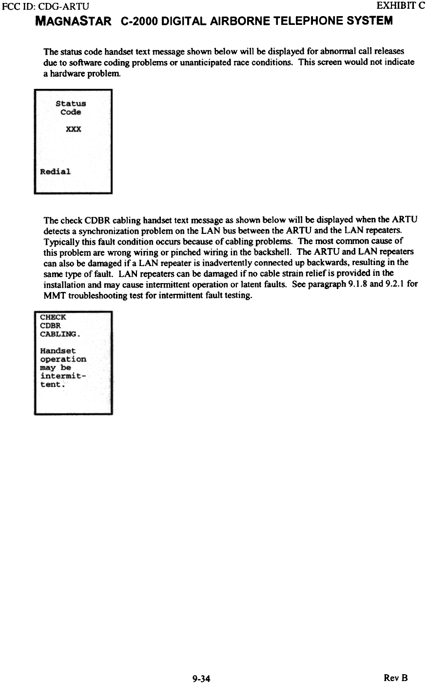
The status code handset text message shown below will be displayed for abnormal call releases
due to software coding problems or unanticipated race conditions. This screen would not indicate
a hardware problem
Status
Code
xxx
Redial
The check CDBR cabling handset text message as shown below will be displayed when the ARTU
detects a synchronization problem on the LAN bus between the ARTU and the LAN repeaters.
Typically this fault condition occurs because of cabling problems. The most common cause of
this problem are wrong wiring or pinched wiring in the backshell. The ARTU and LAN repeaters
can also be damaged if a LAN repeater is inadvertently connected up backwards, resulting in the
same type of fault. LAN repeaters can be damaged if no cable strain relief is provided in the
installation and may cause intermittent operation or latent faults. See paragraph 9.1.8 and 9.2.1 for
MMT troubleshooting test for intermittent fault testing.
RevB
9-34
FCC ill: CDG-ARTU EXHIBIT C
MAGNASTAR C-2000 DIGITAL AIRBORNE TELEPHONE SYSTEM
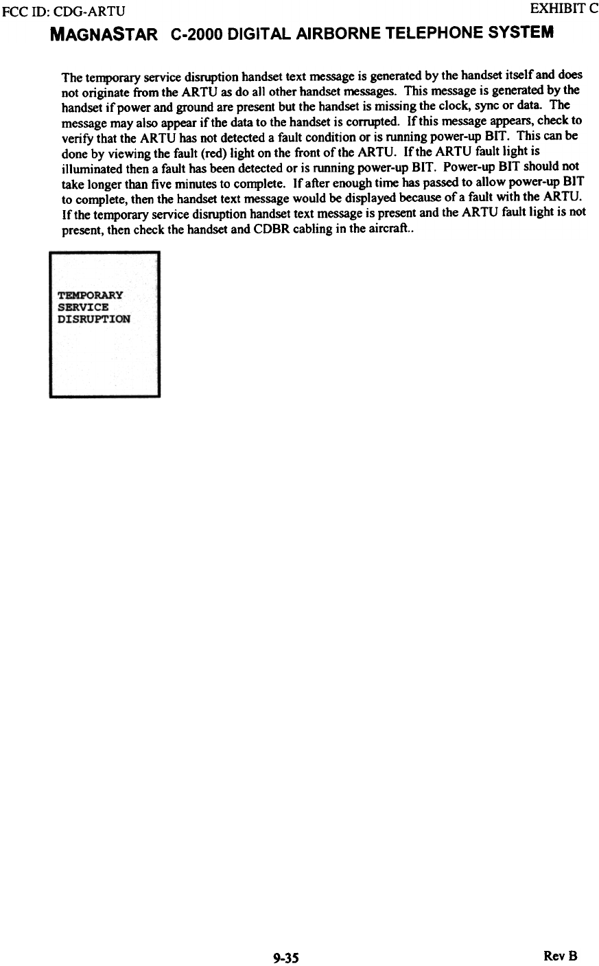
The temporary service disruption handset text message is generated by the handset itself and does
not originate from the ARTU as do all other handset messages. This message is generated by the
handset if power and ground are present but the handset is missing the clock, sync or data. The
message may also appear if the data to the handset is corrupted. If this message appears, check to
verify that the ARTU has not detected a fault condition or is running power-up BIT. This can be
done by viewing the fault (red) light on the front of the ARTU. If the ARTU fault light is
illuminated then a fault has been detected or is running power-up BIT. Power-up BIT should not
take longer than five minutes to complete. If after enough time has passed to allow power-up BIT
to complete, then the handset text message would be displayed because of a fault with the ARTU.
If the temporary service disruption handset text message is present and the ARTU fault light is not
present, then check the handset and CDBR cabling in the aircraft..
TEMPORARY
SERVICE
DISRUPTION
RevS
9-35