Raytheon IIS ARTU Air-Ground Radio System User Manual installation manual part two
Raytheon Company Air-Ground Radio System installation manual part two
Contents
installation manual part two
FCC ID: CDG-ARTU
MAGNASTAR
EXHIBITC
C-2000 DIGITAL AIRBORNE TELEPHONE SYSTEM
CDBR/AIU
a) The mounting location of each CDBR/AIU should be accessible at later times for
system checkout and troubleshooting.
b) Prior to unit installation, perform a visual inspection on each unit for damaged
connectors or mounting hardware.
c) When connecting device cabling to a unit, insure that the connectors are fully engaged
and that the screws joining the connectors are securely fastened. Also ensure that
proper cable strain relief is provided at the unit interface to eliminate possible latent
stress damage problems.
d) Only cables that are to be used with equipment presently installed in the aircraft shall
be connected to each unit (i.e. cables placed in the aircraft for future expansion of
system capabilities shall not be connected to a CDBR/AIU).
Note: Only one digital phone shall be connected to a CDBR digital handset port.
Do not connect more than one digital phone to a CDBR digital handset phone port.
(Do !!.2! make a "split" phone cable to connect two phones or two jacks to one
CDBR phone port.)
HANDSETS
5.1.16.1 Generallnfomation
a) Prior to Handset installation, perform a visual inspection of each Handset and
Handset cable for damaged connectors or mounting hardware.
b) When connecting a Handset to the Handset cabling, insure that the connector is fully
engaged.
c) After the Handset is installed in the aircraft, remove the Handset from its holder and
insure that the Handset cord ratchet mechanism functions properly.
d) Replace the Handset in the holder and insure that the Handset seats properly.
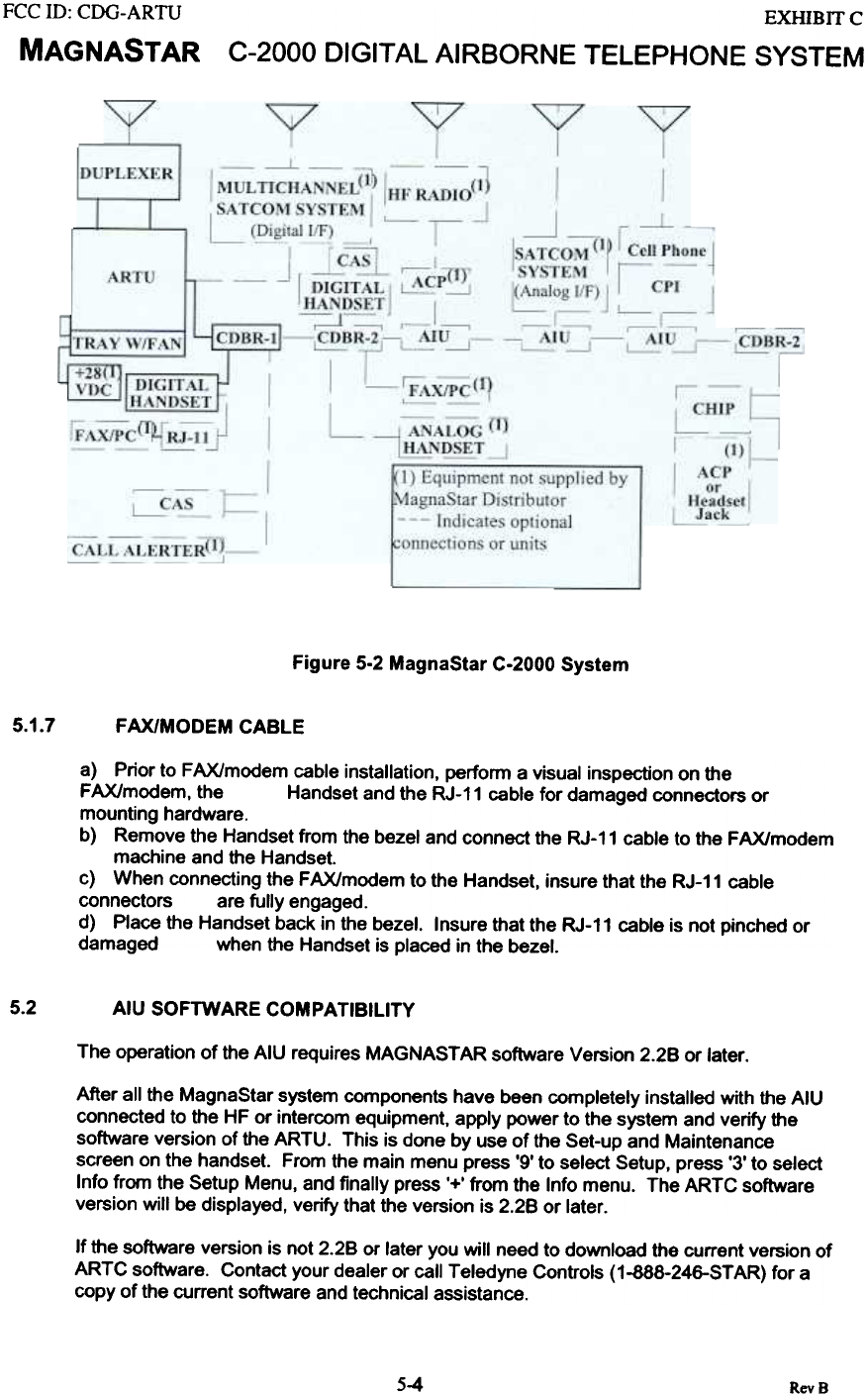
5.1.6.2.1 System Overview
The MagnaStar C-2000 Airborne Radio Telecommunications Unit (ARTU) operates a
Local Area Network (LAN) bus. which LAN repeaters such as the CDBRs and the CAS
use to interface with the ARTU. A Cabin Distribution Bus Repeater model 1 (CDBR-1) is
used to interface one or two digital handsets to the system. A Call Alerter Switch (CAS)
can be used to interface a ringer to each digital handset to the system.
5.1.6.2.2 CDBR-1/Handset Cable (W6)
The CDBR-1/Handset Cable is identified as cable W6 in the C-2000 Interface Control
Document (ICD). If needed, refer to paragraph 2.3.4.1 of the C-2000 ICD for specific
information about the pinouts or components of W6. W6 P1 connects to the CDBR-1 J3
or J4, and P2 provides a connection point for the digital handset
S-3 RevB
FCC ill: CDG-ARTU
MAGNASTAR EXHIBIT C
C-2000 DIGITAL AIRBORNE TELEPHONE SYSTEM
Figure 5-2 MagnaStar C-2000 System
5.1.7 FAX/MODEM CABLE
a) Prior to FAX/modem cable installation, perform a visual inspection on the
FAX/modem, the Handset and the RJ-11 cable for damaged connectors or
mounting hardware.
b) Remove the Handset from the bezel and connect the RJ-11 cable to the FAX/modem
machine and the Handset.
c) When connecting the FAX/modem to the Handset, insure that the RJ-11 cable
connectors are fully engaged.
d) Place the Handset back in the bezel. Insure that the RJ-11 cable is not pinched or
damaged when the Handset is placed in the bezel.
5.2 AIU SOFTWARE COMPATIBILITY
The operation of the AIU requires MAGNAST AR software Version 2.28 or later.
After all the MagnaStar system components have been completely installed with the AIU
connected to the HF or intercom equipment. apply power to the system and verify the
software version of the ARTU. This is done by use of the Set-up and Maintenance
screen on the handset. From the main menu press '9' to select Setup, press '3' to select
Info from the Setup Menu, and finally press '+' from the Info menu. The ARTC software
version will be displayed, verify that the version is 2.28 or later.
If the software version is not 2.28 or later you will need to download the current version of
ARTC software. Contact your dealer or call Teledyne Controls (1-888-246-STAR) for a
copy of the current software and technical assistance.
5-4 RevB
FCC ill: CDG-ARTU
MAGNASTAR EXHIBIT C
C-2000 DIGITAL AIRBORNE TELEPHONE SYSTEM
5.3 AIU FIELD ALIGNMENT PROCEDURE
The following alignment procedure should be used when an AIU is installed and
interfaced to a HF radio or to other equipment, which will require input from J3 pin 3 of
the AIU. This is a manual alignment procedure that adjusts the audio level that is output
at J3 pin 3 of the AIU. The level of this output audio should be set to the specification of
the extemal device that will be using it.
A. Tools And Required Equipment: The following items will be required:
1. Screwdriver: 1/16 Flat Head Adjustment Tool
2. Volt meter
B. Alignment Procedure: The following procedure outlines the required tasks to
perform this alignment.
~Procedure
1Using the specification of the external device. which will receive audio from J3
pin 3 of the AIU. note the nominal level which should be applied to its input for
normal operation.
Audio Input Level for the Extmal Device VAG RMS.
2. Connect the positive lead of the voltmeter to the AlU test point located on the
side of the AIU case and then place the negative lead on any point of the AIU
case. Set the meter to measure AC volts RMS.
3. Using one of the MagnaStar handsets setup a HF link:
From the handset's Main Menu,
Press '6' to select the "Link" option.
Press '3' to select "HF Radio" (this label can be customized).
4. With the HF link now connected continually press (or with ARTC 4.0A software
and above press and release repeatedly) anyone of the handset's numeric
keypad digits to generate a fixed tone. This tone will in turn generate and audio
signal at J3 pin 3 of the AIU.
5. Using the voltage measurement read on the voltmeter and the adjustment
tool/screwdriver, set the AIU audio output level to the level noted in step 1, by
turning the adjustment potentiometer located through the hole in the AIU cover.
6. Tenninate the call and remove the meter. Place the adhesive backed circular
aluminum cover PN 513917-2 packed with the unit over the AIU adjustment hole.
5-5 RevB
FCC ill: CDG-ARTU
MAGNASTAR
EXHIBIT C
C-2000 DIGITAL AIRBORNE TELEPHONE SYSTEM
EQUIPMENT CHECKOUT WIffi MAGNAST AR MAINTENANCE
TERMINAL (MMT)
6.0 EQUIPMENT CHECKOUT WITH MAGNASTAR MAINTENANCE TERMINAL (MMT) ..6-1
6.1 INTRODUCTION 6-1
6.2 TEST EQUIPMENT REQUIREMENTS 6-1
6.3 C-2000 INST ALLA TION CHECKOUT with MMT 6-2
6.3.1 MMT COMPUTER SET-UP 6-2
6.3.2 MMT CABLE CONNECTION "'...'...' " "..' "'.'.' 6-2
6.3.3 EXECUTING MMT SOFTW ARE 6-2
6.3.4 MMT OPERATION 6-3
6.3.5 INTRODUCnON TO THE MMT INSTALLATION TUTORIAL 6-4
6.3.6 C-2000 SYSTEM POWER UP 6-5
6.3.7 MMT COMMUNICATION VERIFICATION 6-6
6.3.8 START ARTU OPERATIONAL SOFTW ARE 6-7
6.3.9 LOCKED OFF-LINE STATE 6-10
6.3.10 ARTU MOUNTING TRAY FAN TEST 6-11
6.3.11 ARTU TRANSMITTER POWER OUTPUT MEASUREMENT 6-12
6.3.12 RECEIVE SIGNAL STRENGTH MEASUREMENT 6-14
6.3.13 HANDSET I LAN TEST 6-17
6.3.14 RESET MAINTENANCE ACCESS PIN 6-18
6.3.15 UNLOCKED ONLINE STATE 6-19
6.3.16 RECEIVE SIGNAL STRENGTH MEASUREMENT USING GENSTAR GROUND
ST A TION 6-20
6.3.17 C-2000 INSTALLATION CONCLUSION 6-22
RevB
6-i
FCC ID: CDG-ARTU
MAGNASTAR
EXHlBrrc
C-2000 DIGITAL AIRBORNE TELEPHONE SYSTEM
6.0 EQUIPMENT CHECKOUT WITH MAGNASTAR MAINTENANCE TERMINAL (MMT)
6.1 INTRODUCTION
The MagnaStar Maintenance Terminal (MMT) consists of a laptop computer executing application
software. The MMT is connected to the ARTU via the computer's serial port. The MMT is used
to control the ARTU and monitor its functions. The MMT software includes an Installation
Tutorial. This tutorial is a step-by-step procedural test that verifies the C-2000 installation. When
the tutorial runs a particular test, a description of the test, the expected results of the test, and the
actual results of the test will be displayed to the user. A troubleshoot screen is also available with
each test step that provides a short description of steps to use for troubleshooting the system.
The MMT is a very powerful tool for verifying and troubleshooting a MagnaStar C-2000
installation.
This section of the equipment checkout provides a text description for each individual test step of
the MMT and a procedure with the necessary steps to accomplish each test step. The text
describing the necessary steps to perform each test are shown in bold print.
Cable checkout, Section 4.0, and equipment installation, Section 5.0, should be completed before
starting this section. Troubleshooting procedures screens are available while using the MMTI.
These screens and troubleshooting information can be found in Section 9.0.
The following MMTI screen information corresponds with MMTI software version 4.0.A.
6.2 TEST EQUIPMENT REQUIREMENTS
The following list defines the test equipment necessary to completely check the functionality of
the C-2000 system using the MagnaStar Maintenance Terminal.
1) MagnaStar MMT Installation software version 4.0 (MX 902156)
2) 386 or 486 IBM compatible computer with 4 Megabytes of extended RAM
3) Power Meter or Thru-line Watt meter for 895 MHz (20 watt minimum capability @ 900 MHz)
4) MMT cable (MX 422632-801)
5) MagnaStar Loop-Around Test Set (MX 902185-802)
6-: RevS
FCC ill: CDG-ARTU
MAGNASTAR
EXHIBITC
C-2000 DIGITAL AIRBORNE TELEPHONE SYSTEM
6.3 C-2000 INSTAllATION CHECKOUT with MMT
The installer must know the following information before starting the MMT Installation:
a) The number of CDBRs and AIU's that are used in the installation.
b) The number of Handsets that are to be used in the installation.
c) If the location at which the installation is being performed will support
communications with a GTE AIRFONE GenStarTM System Ground Station.
6.3.1 MMT COMPUTER SET-UP
See Section 8 for computer set-up.
6.3.2 MMT CABLE CONNECTION
The MMT computer is to be connected to the ARTU using the MMT cable. (The MMT interface is a RS-
232C serial interface.)
Connect the 9 pin D type connector of the MMT cable to the "COM .. port of the MMT
computer.
Remove the protective cap from the MMT connector of the ARTU.
Connect the circular connector of the MMT cable to the MMT connector on the ARTU.
6.3.3 EXECUTING MMT SOFTWARE
The following commands are to be used to start execution of the MMT application software in the
computer.
If required. power up the computer and wait for the computer to complete the boot
process. It is assumed that the computer will boot up to the "C" drive with and
have no other applications running.
Change the directory to the MTU directory, type: "CD MTU and press "ENTER",
C:> cd mtu
To start execution of the MMT software from the MTU directory, type: "MMTI" and
press "ENTER".
C:\MTU> mmti
Note: when the computer is executing the MMT software. the computer will be
referenced as the "MMr .
RevB
6-2
FCC ID: CDG-ARTU
MAGNASTAR
EXHIBITC
C-2000 DIGITAL AIRBORNE TELEPHONE SYSTEM
6.3.4 MMT OPERATION
This step selects the installation tutorial mode of operation for the MMT from the from the start-up
options menu after the MMT software has started execution.
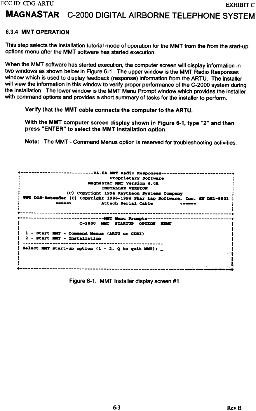
When the MMT software has started execution, the computer screen will display information in
two windows as shown below in Figure 6-1. The upper window is the MMT Radio Responses
window which is used to display feedback (response) information from the ARTU. The installer
will view the information in this window to verify proper performance of the C-2000 system during
the installation. The lower window is the MMT Menu Prompt window which provides the installer
with command options and provides a short summary of tasks for the installer to perform.
Verify that the MMT cable connects the computer to the ARTU.
With the MMT computer screen display shown in Figure 6-1, type "2" and then
press "ENTER" to select the MMT Installation option.
Note: The MMT - Command Menus option is reserved for troubleshooting activities.
+ V'.OA HNT Radio Re8PQaae +
: Proprietary Soft~e :
: MagDaStar HNT Version'. OA :
: IKS'1'ALLD VDS%c. :
: (C) Copyright 1.99' Raytheon Syst- C~ :
: ~ DOS-8xt8Dd8r (C) Copyright 1.986-1.99' Pbar Lap Soft~., %Dc. .. D81.-9S03 :
: > Attach Seria1. Cable < :
I I
I I
+ +
+ HNT ~u ~t +
I C-2000 ~ STARTUP OP'1'%c. .au :
I I
I I
: 1. - Start." - C~ NeDus ( UTO or CDB%) :
: 2 - Start." - %D8tallatiOD I
: I
: Select .-'!' .tart-up option (1. - 2, Q to QUit ~): - :
. f
I
I .
I J
I t
I .
+ ~~~~
Figure 6-1. MMT Installer display screen #1
6-3 RevB
MAGNASTAR C-2000 DIGITAL AIRBORNE TELEPHONE SYSTEM
6.3.5 INTRODUCTION TO THE MMT INSTAllATION TUTORIAL
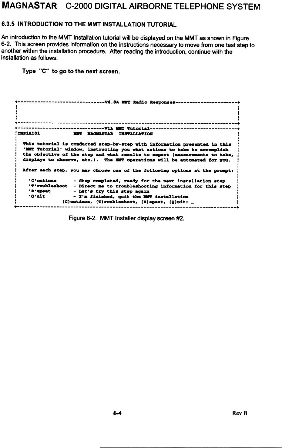
An introduction to the MMT Installation tutorial will be displayed on the MMT as shown in Figure
6-2. This screen provides information on the instructions necessary to move from one test step to
another within the installation procedure. After reading the introduction, continue with the
installation as follows:
Type "C" to go to the next screen.
+ V~.OA.-T -.dio Re8PQD8 +
I I
, I
, I
I ,
I I
I I
+ +
+ V~.-T Tutorial +
: ms~Ol .-T D8ASTAa m8TALLATX~ :
I I
I I
: fti. tutorial i. cODdlacted .tep-by-.tep with iAf~ti~ pr.._ted iD thi. :
: '-.or Tutorial' wiDdow, iD8tructiAg you what actioaa to take to acca8Pliah :
I the Objeotiv. of the .tep aDd what r..ult. to expect (...8Ur888Dt. to tak., :
: di8Playa to Ob8erve, etc.). ~.-T operati0D8 will be aut~te4 for you. I
I I
I I
: After -oh .tep, you ~ choo.. ODe of the followiDg optioaa at the PZ'a8Pt: :
I ,
I I
: ' c ' ~tiaa. - Step ca8Pl.ted, r.ady for th8 D8Xt iDatallatiOD .tep :
: '7'roubl..hoot - Direct.. to troubl..hootiDg iDfor8&tiOD for thi. .tep :
: '.'epeat - Let'. try thi. .tep agaiA I
: 'Q'uit - X'a fiDi.be4, quit th8 -.or iDatallatiOD :
I (C)~tiaa., (T)rouble.hoot, (a)epeat, (Q)uitl - :
+ +
Figure 6-2. MMT Installer display screen #2.
6-4 RevB
FCC ill: CDG-ARTU
MAGNASTAR
EXHIBIT C
C-2000 DIGITAL AIRBORNE TELEPHONE SYSTEM
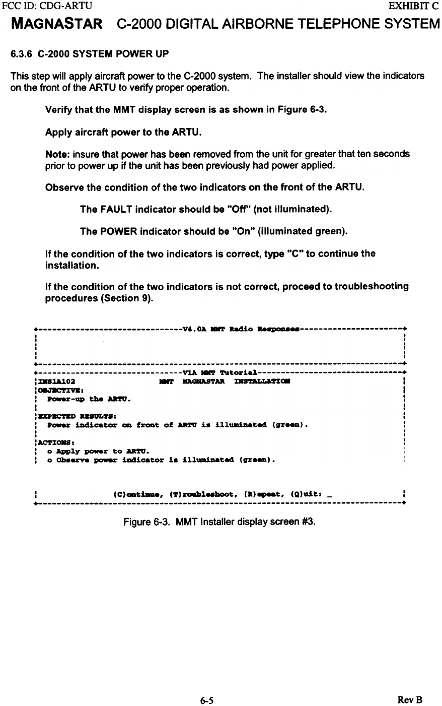
6.3.6 C-2000 SYSTEM POWER UP
This step will apply aircraft power to the C-2000 system. The installer should view the indicators
on the front of the ARTU to verify proper operation.
Verify that the MMT display screen is as shown in Figure 6-3.
Apply aircraft power to the ARTU.
Note: insure that power has been removed from the unit for greater that ten seconds
prior to power up if the unit has been previously had power applied.
Observe the condition of the two indicators on the front of the ARTU.
The FAULT indicator should be "Off" (not illuminated).
The POWER indicator should be "On" (illuminated green).
If the condition of the two indicators is correct, type "C" to continue the
installation.
If the condition of the two indicators is not correct, proceed to troubleshooting
procedures (Section 9).
+ V..OA NNT Radio ~ +
I ,
, ,
I I
I I
I I
I I
+ +
+ ~ NNT Tu~ori~ +
: D81A.102 .., ~TD. msULLA.ft~ I
:~I I
: Power-up tb8 U'IU. :
I I
I I
: DnCftD "~81 :
: Power ill4ic.~or OD f~~ of ARTU i. illuaiDa~ed (gZ'.~). :
I I
I I
:ACT%~I :
: 0 Apply poweZ' to D.ft. :
: 0 Ob8~ poweZ' iDdicatoZ' i. illuaiDa~ed (gZ"~). :
j (C)OD~iau8, (~)zoab~88boo~, (.)8P88~, (Q)ai~1 - :
+ +
Figure 6-3. MMT Installer display screen #3.
RevB
6-5
FCC ill: CDG-ARTU
MAGNASTAR
EXHffiIT C
C-2000 DIGITAL AIRBORNE TELEPHONE SYSTEM
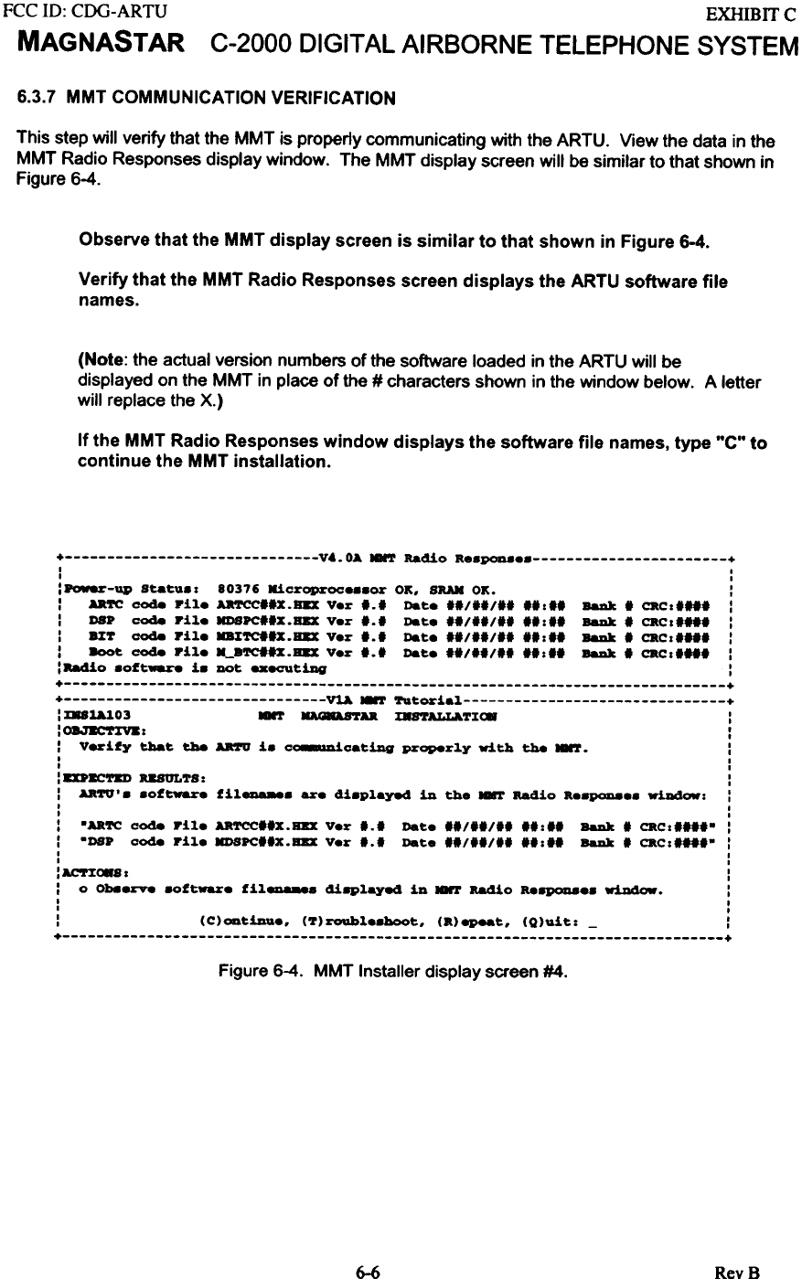
6.3.7 MMT COMMUNICATION VERIFICATION
This step will verify that the MMT is properly communicating with the ARTU. View the data in the
MMT Radio Responses display window. The MMT display screen will be similar to that shown in
Figure 6-4.
Observe that the MMT display screen is similar to that shown in Figure 6-4.
Verify that the MMT Radio Responses screen displays the ARTU software file
names.
(Note: the actual version numbers of the software loaded in the ARTU will be
displayed on the MMT in place of the # characters shown in the window below. A letter
will replace the X.)
If the MMT Radio Responses window displays the software file names, type "C" to
continue the MMT installation.
+ V..OA ~ Radio aesp0a8es +
I I
I I
:Pow8r-up Statusz 80376 Kicroproeessor OK. SRAN OK. :
: AaTC code rile ~IIX.s.x Ver 1.1 Date IIIIIIII 11:11 BaDk I CRCzlll1 :
: os. code rile HDSPCllx.BBX Ver 1.1 Date IIIIIIII 11:11 BaDk I CRCzIIII :
: 8%T code rile KaXTClIX.s.x Ver 1.1 Date IIIIIIII 11:11 BaDk I CRCzIIII :
: 8oot code rile M_8TC1IX.s.x Ver 1.1 Date IIIIIIII 11:1' BaDk, CRCz"" :
: -.410 sort~ is DOt -ecuting :
+ +
+ VlA MMT Tutorial +
: mBlAl03 ~Aa mSTALLA.TXC8 :
'O8.J.corxv.z I
I I
: Veriry that tha Aftr1 is c~cating properly with tha ~. :
I I
I I
: DnC'1'8D RUULTS: :
: Aa'l'U' s sor~e ril_s are displayed in the ~ Radio ae8P0D8es wiDdOlfz :
I I
I I
: -AaTC c0d8 rile ARTCC"X.BBX Ver 1.1 Date "/"1,' 11:11 BaDk I CRCzI",- :
: -os. c0d8 rile HDSPC"X.BBX Ver 1.1 Date fl/"/ll 11:11 BaDk I CRCz"I'- :
I I
I I
:AC'r:tC8Sz :
: 0 Oh8erve 8Ort~e ril- displayed in ~ Radio Re8P0D8es wiJIdow. :
I I
I ,
: (C)ootiDue. (T)roableshoot. (R)epeat. (Q)uit: - :
+ +
Figure 6-4. MMT Installer display screen #4.
6-6 RevS
FCC ill: CDG-ARTU
MAGNASTAR
EXHIBIT C
C-2000 DIGITAL AIRBORNE TELEPHONE SYSTEM
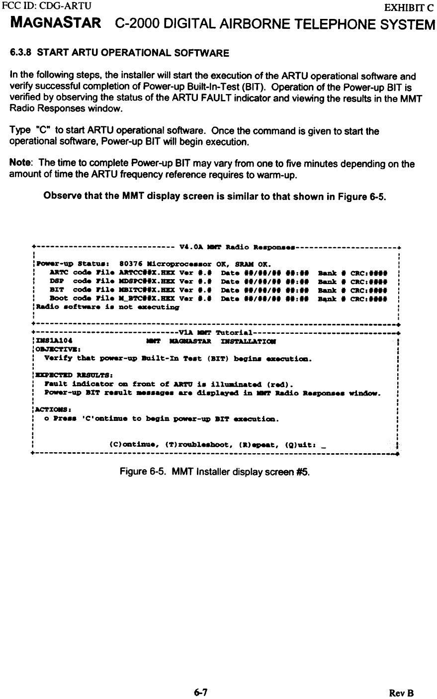
6.3.8 START ARTU OPERATIONAL SOFTWARE
In the following steps. the installer will start the execution of the ARTU operational software and
verify successful completion of Power-up Built-ln- Test (BIT). Operation of the Power-up BIT is
verified by observing the status of the ARTU FAULT indicator and viewing the results in the MMT
Radio Responses window.
Type "C" to start ARTU operational software. Once the command is given to start the
operational software. Power-up BIT will begin execution.
Note: The time to complete Power-up BIT may vary from one to five minutes depending on the
amount of time the ARTU frequency reference requires to warm-up.
Observe that the MMT display screen is similar to that shown in Figure 6-5.
+ V4.0A -.T Radio aespouaes +
I I
I I
:Pow8r-up Btatusz 80376 Microprocessor OK, BRAN OK. :
: AaTC code rile AaTCC'Ix.RBX Ver 1.1 Date .1/.'1'1 Ilzll BaDk I CRCzI'" :
: DBP code rile HDSPC"x.RBX Ver 1.1 Date "1"/'1 IIz" BaDk I CRcz.'" :
: BZT code rile HBZTCI.x.BBX Ver 1.1 Date "1"/" "zI' BaDk, CRcz"" :
: Boot code rile H_BTC"X.BBX Ver 1.1 Date '.1"1" "Z" ~. CRcz"" :
: Radio software is Dot executing :
, ,
I ,
+ +
+ ~ -.T Tutorial +
: mBU.lO. 8'1' KAC8AS'1'U ZRS'l'ALLA'1'I<8 t
: 08J8C'fIV8: I
: V.rify that pGW8r-ap BQilt-ID T..t (BI'1') begiua executioa. I
I I
I I
: DPBCftD auUL'l'S: :
: hult iDdicator CD front of AR'l'O i. ill1miDated (red). :
: Power-up 81'1' re.ult _..ag.. are 4iaplayed in -.T Radio a.8PQD8.. window. :
I I
I I
:AC'rZ~s I
I 0 Pr... 'C'CDtiDDe to begiD pGW8r-ap BIT ..ecutiCD. I
t I
I I
I I
I I
: (C)~tinu., (T)roabl.8hoot, (a)~t, (Q)1Iits - ~
+ +
Figure 6-5. MMT Installer display screen #5.
6--7 RevB
FCC 10: CDG-ARTU
MAGNASTAR
EXHIBITC
C-2000 DIGITAL AIRBORNE TELEPHONE SYSTEM
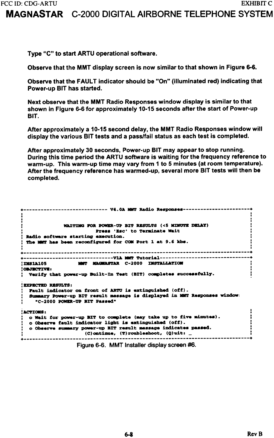
Type "c" to start ARTU operational software.
Observe that the MMT display screen is now similar to that shown in Figure 6-6.
Observe that the FAULT indicator should be "On" (illuminated red) indicating that
Power-up BIT has started.
Next observe that the MMT Radio Responses window display is similar to that
shown in Figure 6-6 for approximately 10-15 seconds after the start of Power-up
BIT.
After approximately a 10-15 second delay, the MMT Radio Responses window will
display the various BIT tests and a pass/fail status as each test is completed.
After approximately 30 seconds, Power-up BIT may appear to stop running.
During this time period the ARTU software is waiting for the frequency reference to
warm-up. This warm-up time may vary from 1 to 5 minutes (at room temperature).
After the frequency reference has warmed-up, several more BIT tests will then be
completed.
+ Vt.OA NNT Radio a..pQD8 +
I I
I I
I I
I I
: DZ~ 1'0. ~-OP B%T USULTS «5 HDO'rB ~T) :
: pr... 'B.c' to Texaioat. Wait :
: aa4io 8Of~. .taRing _cuti~. :
: ~ 8!' baa ~ recca.figured for ~ Port 1. at 9.6 kh8. :
I I
I I
+ +
+ ~ 8!' Tutorial +
: DSUJ.O5 8!' U'IU C-2000 mSTALL&T%<* :
:o ac"i'%V8. :
: Verify tbat power-up 8Qilt-%D Teat (B%T) CO8Pl.t.. 8Ucc...fu1.1.y. !
: BDBC'l'BD USOLTS:
: Fault iD4icator CD frCDt of ARTU i. extiDgUi.be4 (off).
: s-zy ~r-up B:IT r..ult _..ag. i. 4iaplay8d in ~ ".apoD8.. wiJJ4ow:
: .C-2000 ~-OP BrT pa..84.
: AC'nC8S : :
: 0 wait for paw8r-up 8I~ to CQ8Plete (aay take up to five aiaat..). :
: 0 Ob8erve fault iDdicator light i. .xtiDgui8bad (off). :
: 0 Ob8erve -ry ~-up 8%~ re.ult -.-ge iDdicate. paa-S. :
: (C)ODtimue, (~)roable8boot, (Q)uit: - :
+ +
Figure 6-6. MMT Installer display screen #6.
RevS
6-8
FCC 10: CDG-ARTU
MAGNASTAR EXHIBIT C
C-2000 DIGITAL AIRBORNE TELEPHONE SYSTEM
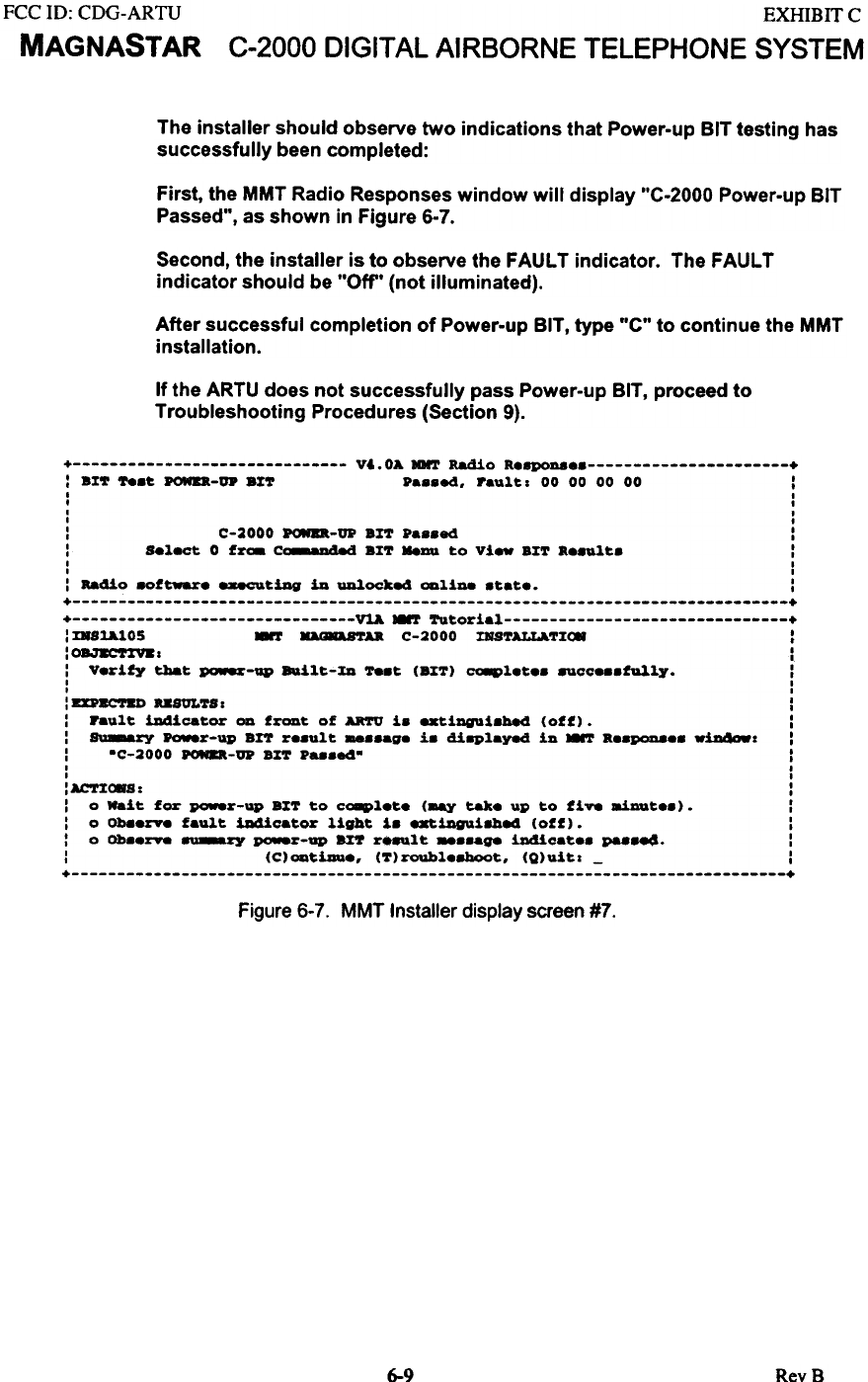
The installer should observe two indications that Power-up BIT testing has
successfully been completed:
First, the MMT Radio Responses window will display "C-2000 Power-up BIT
Passed", as shown in Figure 6-7.
Second, the installer is to observe the FAULT indicator. The FAULT
indicator should be "Off" (not illuminated).
After successful completion of Power-up BIT. type .'C" to continue the MMT
installation.
If the ARTU does not successfully pass Power-up BIT, proceed to
Troubleshooting Procedures (Section 9).
+ V&.OA HMT Radio Re8PQDa +
: .X~ 78.~ POWER-UP ax~ pa..ed. raul~: 00 00 00 00 :
. I
. I
, I
, I
: C-2000 ~-UP arr pa..ed :
: S.l8C~ 0 f~ C_auded .X'1' Meuu to vi- ax'1' a..ult. :
, ,
, ,
: Radio .of~ _tiDg iD UDloeked ~liDe .tat.. :
+ +
+ ~.-'!' '1'utorial +
: mSlAlOS .-r D.-aB'1'U C-2000 ms'1'ALLA.'1'X~ :
""-O=---=~-~ I
, : I
: V.rity ~t ~-up a.ilt-%D 78.t (B%'!') CO8pl.t.. 8Ucc...fu1~y. :
I I
I I
: UPBC'rBD USUL'1'S: :
: Fault iDdicator OD froDt of AR'1'U i. axtiDgui.hed (off). :
: S-zy ~r-up an r..ult _..ag. i. diaplay.a iD ~ ...P0D8'. wiD4ow: :
: .C-2000 POM8R-UP Brr P...ed. :
I ,
I ,
:AC'1':EC8S: :
: 0 Mait for po.er-up a%'1' to ca8pl.t. (aay ~. up to fiV8 aiDQt..). :
: 0 Oba.rY8 fault iD4icator light i. axtiDguiahed (off). :
: 0 Oh..rY8 ~ po.er-up err r.nlt _..age iDdicat.. paa~. :
: (C)ODtiDa., ('1')roahl.8hoot, (Q)uitz - :
+ +
Figure 6-7. MMT Installer display screen #7.
6-9 RevB
FCC ill: CDG-ARTU
MAGNASTAR
EXHIBITC
C-2000 DIGITAL AIRBORNE TELEPHONE SYSTEM
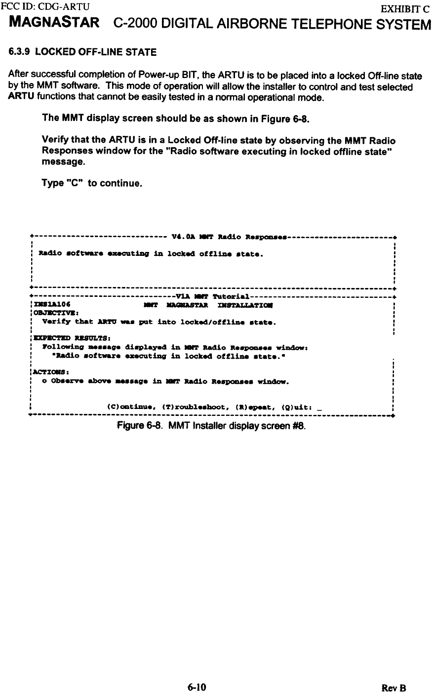
6.3.9 LOCKED OFF-LINE STATE
After successful completion of Power-up BIT. the ARTU is to be placed into a locked Off-line state
by the MMT software. This mode of operation will allow the installer to control and test selected
ARTU functions that cannot be easily tested in a normal operational mode.
The MMT display screen should be as shown in Figure 6-8.
Verify that the ARTU is in a Locked Off-line state by observing the MMT Radio
Responses window for the "Radio software executing in locked offline state"
message.
Type "C" to continue.
+ V..OA NNT aadio a.SP0D8.s +
I I
I .
: Radio software exeeu~iDg in locke4 offline s~a~.. :
I I
I .
I I
I I
I I
I I
+ +
+ VtA ~ Tu~orial +
: IaUlO6 ~ D8AS'rAR. x.8'rALLa.7X~ :
:OBJBC'nftz :
: Verify tha~ AaTO ... pQ~ in~o locked/offline s~a~.. :
I I
I I
: DP~-TKU RESULTS:
: Following _..age di8Played in Iarr Radio aeap0D8e. wiDdowz
: -Radio aoftware executiDg in locked offliDe atate.-
+ +
Figure 6-8. MMT Installer display screen #8.
6-10 RevB
I I
I I
:ACTZ~S: :
: 0 Ob88rv8 above -."9. in .-r Bad1o R..pcaa.. window. :
I I
I I
I I
I I
: (C)ODtinU.. (T)roubl..hoot. (R)epeat. (Q)uit: - :
FCC ID: CDG-ARTU
MAGNASTAR
EXHffiIT C
C-2000 DIGITAL AIRBORNE TELEPHONE SYSTEM
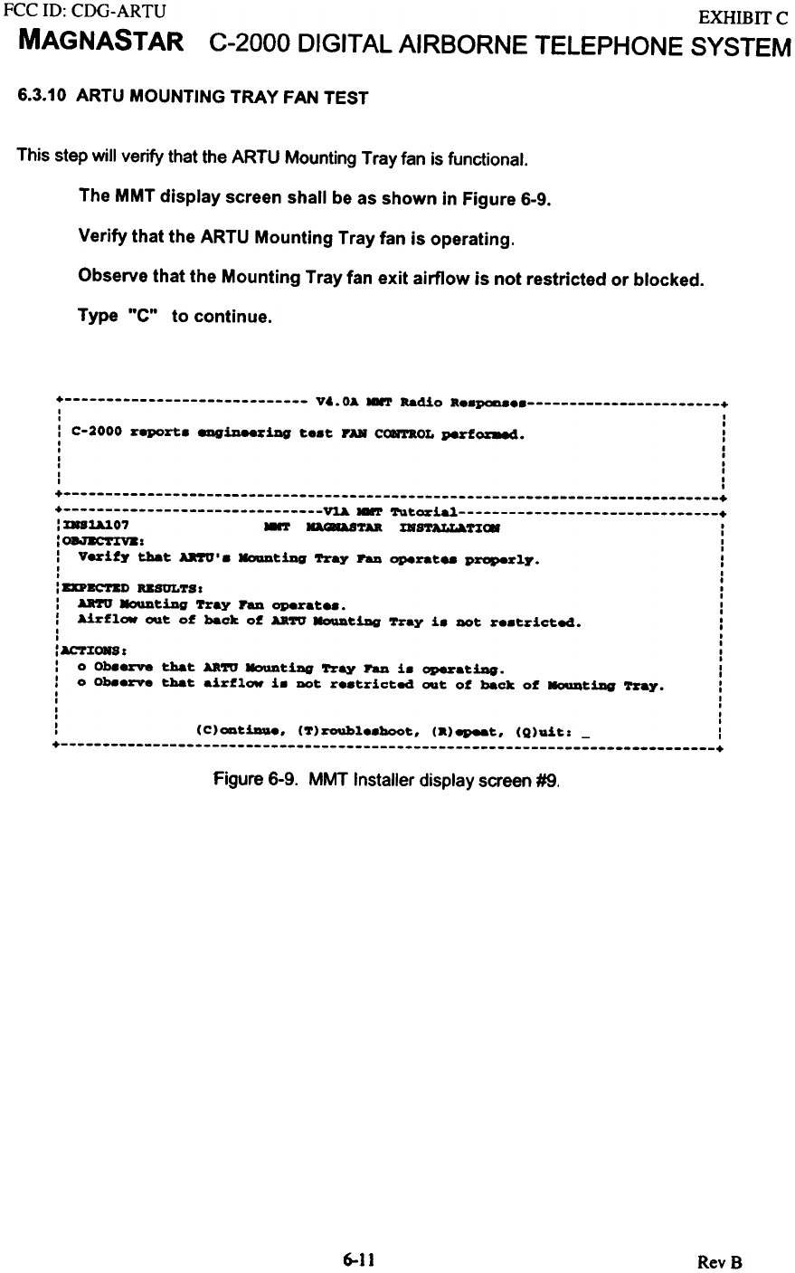
6.3.10 ARTU MOUNTING TRAY FAN TEST
This step will verify that the ARTU Mounting Tray fan is functional.
The MMT display screen shall be as shown in Figure 6-9.
Verify that the ARTU Mounting Tray fan is operating.
Observe that the Mounting Tray fan exit airflow is not restricted or blocked.
Type "C" to continue.
+ Vt.OA HMT Radio a..pooa +
I I
I I
: C-2000 report. ~~~iDg t..t FA» CC*TaOL perf~. :
I I
I I
I I
I I
I I
I I
+ +
+ ~ HMT TutQ&"~ +
: x..~O7 8T lI&8&S'l'AR mSTALLAT1:C8 :
:08J8C'r:EV8: :
: Vez-ifJ' that U'I'U'. KoaDtiDg '!'ray PaD operat.. ~1J'. :
I I
I I
: DPBC'l'BD USUL'l'S I :
: ARft MoIIDtiDg 'rray PaD operat... :
: Airfl~ ~t o~ back of AR'l'U NoaDtiDg 'l'ray i. QOt r..tricted. :
I I
I I
:AC'l'%~1 :
: 0 Ob8ezve that AR'l'U ~tiDg '!'ray PaD i. opezoatiDg. :
: 0 ob8.rve that air~l~ i. QOt r..tricted ~t of back of MoIIDtiDg '!'ray. :
I I
I I
I I
I I
: (C)ODt1au.. ('l')roUbl..boot. (a)epeet. (Q)uit: - :
+ +
Figure 6-9. MMT Installer display screen #9.
6-11 RevB
FCC ID: CDG-ARTU
MAGNASTAR
EXHIBITC
C-2000 DIGITAL AIRBORNE TELEPHONE SYSTEM
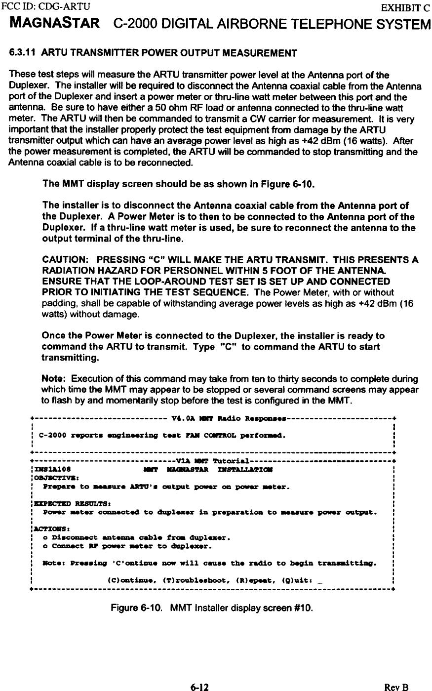
6.3.11 ARTU TRANSMITTER POWER OUTPUT MEASUREMENT
These test steps will measure the ARTU transmitter power level at the Antenna port of the
Duplexer. The installer will be required to disconnect the Antenna coaxial cable from the Antenna
port of the Duplexer and insert a power meter or thru-line watt meter between this port and the
antenna. Be sure to have either a 50 ohm RF load or antenna connected to the thru-line watt
meter. The ARTU will then be commanded to transmit a CW carrier for measurement. It is very
important that the installer properly protect the test equipment from damage by the ARTU
transmitter output which can have an average power level as high as +42 dBm (16 watts). After
the power measurement is completed. the ARTU will be commanded to stop transmitting and the
Antenna coaxial cable is to be reconnected.
The MMT display screen should be as shown in Figure 6-10.
The installer is to disconnect the Antenna coaxial cable from the Antenna port of
the Duplexer. A Power Meter is to then to be connected to the Antenna port of the
Duplexer. If a thru-line watt meter is used, be sure to reconnect the antenna to the
output terminal of the thru-line.
CAUTION: PRESSING "c" WILL MAKE THE ARTU TRANSMIT. THIS PRESENTS A
RADIATION HAZARD FOR PERSONNEL WITHIN 5 FOOT OF THE ANTENNA.
ENSURE THAT THE LOOP-AROUND TEST SET IS SET UP AND CONNECTED
PRIOR TO INITIATING THE TEST SEQUENCE. The Power Meter, with or without
padding, shall be capable of withstanding average power levels as high as +42 dBm (16
watts) without damage.
Once the Power Meter is connected to the Duplexer, the installer is ready to
command the ARTU to transmit. Type "C" to command the ARTU to start
transmitting.
Note: Execution of this command may take from ten to thirty seconds to complete during
which time the MMT may appear to be stopped or several command screens may appear
to flash by and momentarily stop before the test is configured in the MMT.
+ vt.OA HHT Radio R..p0a8 +
: I
: C-2OOO r.port. ~.x-iDG t..t PAR ~OL ~rf~. :
I ,
I ,
+ +
+ ~ MMT Tutorial +
: ms~O8 ~ D8AS'l'U mftALLl.tlI~ :
: 08JKC'1'IV8: :
: .r~ to -.ur. Aa'rO'. ~tPlt po-.r OD po-.r _t.r. :
I I
I I
: BDBC'l'BD USULTS: :
: .~ -ter ~ct~ to dupl_.r in pr.paratiOD to -a~ ~r ~tPI&t. :
I I
I I
:ACTI~S: :
: 0 Di.coaaect aut8DD& cable fro. 4upl_er. :
: 0 Coaaect BP ~r _ter to 4upl.-r. :
I I
I I
: Bot.: pzo_.iag 'C'ODtinU. - will caus. th. radio to begin t~ttiDG. :
I I
I I
: (C)oatiau.. (tI)roubl..hoot. (R)epeat. (Q)uit: - :
+ +
Figure 6-10. MMT Installer display screen #10.
6--12 RevB
FCC ill: CDG-ARTU
MAGNASTAR
EXHIBITC
C-2000 DIGITAL AIRBORNE TELEPHONE SYSTEM
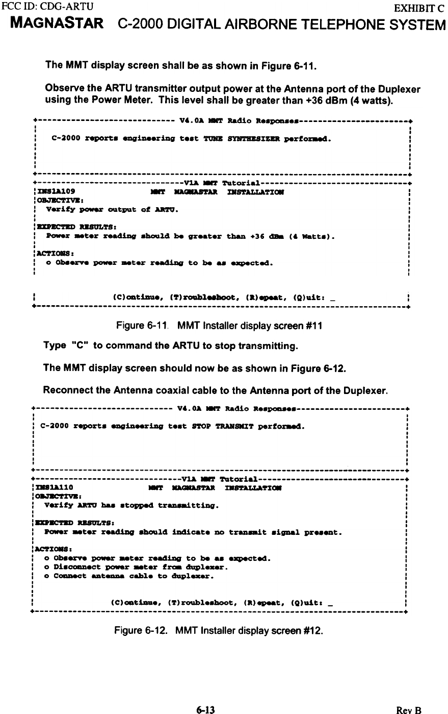
The MMT display screen shall be as shown in Figure 6-11.
Observe the ARTU transmitter output power at the Antenna port of the Duplexer
using the Power Meter. This level shall be greater than +36 dBm (4 watts).
+ V6.0A MHT Radio ae.POD.e +
I I
I .
: C-2000 report;. eqiDeeriDg te.t TOMB SYBTBUXZD perfoz-.cl. :
I I
I I
I .
I I
I I
I I
+ +
+ ~ MMT TUtorial +
: XBSU3.09 MMT ~U DS'l'ALLATXC8 :
:0BJBC'1'%V81 :
: Verify power OIItput of AR'1'IJ. :
I I
I I
: ZD~TED USULTS: :
: Pow.r ..ter re&diDg .bould be greater thaD +36 dB8 (6 Watt.). :
I I
I I
: AC'1'%~ : :
: 0 Ob88%V8 po-.r _ter r8a4iDg to be - expectad. :
I I
I I
: (C)OD~iDu., (7)roable8boo~, (.)epea~, (Q)ul~: - :
+ +
Figure 6-11, MMT Installer display screen #11
Type "C" to command the ARTU to stop transmitting.
The MMT display screen should now be as shown in Figure 6-12.
Reconnect the Antenna coaxial cable to the Antenna port of the Duplexer.
+ V'.OA HNT Radio a..p0a8 +
I I
I I
: C-2000 report. 811GiDeeriDg t..t S'l'OP TRANSIa'1' perfoz88c!. :
I I
I I
I I
I I
I I
I I
I I
I I
+ +
+ V~ ~ Tutorial +
: D81A1.10 ~ ~'1'U m8'1'ALLa.n~ :
:~r :
: Verify AaTU has .topped trU18aittiDg. :
I I
I I
: DnC'1'ZD USOLTS r :
: Po-.r -ter r.a4iDg .hOIald iDdicat. DO t~t .igDal pr..ent. :
I I
I I
:ACT%C8Sr :
: 0 Ob.8rV'8 power -ter readiDg to be - expected. :
: 0 Di.~.ct power _ter f~ d'iPlexer. :
: 0 C_t ant- cable to d1iplexer. :
I I
I I
I I
I I
: (C)ODtiDa., (~)roubl..hoot, (a)~t, (Q)uitl - :
+ +
Figure 6-12. MMT Installer display screen #12.
6-13 RevB
FCC ill: CDG-ARTU
MAGNASTAR
EXHffiIT C
C-2000 DIGITAL AIRBORNE TELEPHONE SYSTEM
6.3.12 RECEIVE SIGNAL STRENGTH MEASUREMENT
This step will use the ARTU to measure the Receive Signal Strength (RSS) of the C-2000 system
in an RF loop-around configuration using the MagnaStar Loop-Around Test Set. This test will
verify the performance of the aircraft RF interface between the ARTU and the Antenna.
In this test, the ARTU will transmit a OAM signal at frequency of 894.9495 MHz. This signal will
be frequency translated (i.e. mixed) by 45 MHz to a frequency of 849.9495 MHz and transmitted
back to the ARTU via the MagnaStar Loop-Around Test Set. Both the TSC and Pilot receivers
are tuned to the receive frequency. The installer is to the view the RSS value of the loop-around
signal to verify the RF signal path of the C-2000 system.
The following steps are to be used with the MagnaStar Loop-Around Test Set.
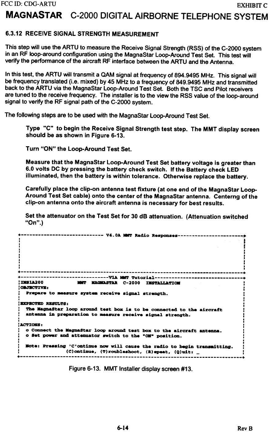
Type "C" to begin the Receive Signal Strength test step. The MMT display screen
should be as shown in Figure 6-13.
Turn "ON" the Loop-Around Test Set.
Measure that the MagnaStar Loop-Around Test Set battery voltage is greater than
6.0 volts DC by pressing the battery check switch. If the Battery check LED
illuminated, then the battery is within tolerance. Otherwise replace the battery.
Carefully place the clip-on antenna test fixture (at one end of the MagnaStar Loop-
Around Test Set cable) onto the center of the MagnaStar antenna. Centerng of the
clip-on antenna onto the aircraft antenna is necessary for best results.
Set the attenuator on the Test Set for 30 dB attenuation. (Attenuation switched
"On".)
+ v~. OA HNT Radio K8.P0D88 ~~
: t
'I,
I I
, I
I ,
I ,
I ,
I I
, I
, I
+ +
+ ~ MMT Tutorial +
: :laU200 8'r DaASTU C-2000 :EU~nC8 I
:08.7E'r:EV81 :
: Prepare to _a.ur8 8Y8t- r8C8i~ .igDal .treDgth. I
, I
, ,
: DPac-~ RB8ULTS I I
: Tbe HagnaStar loop aroaDd t..t box i. to be CODDeCted to the aircraft I
: _t- in preparati~ to ~ rec.i~ .ignal .tr8Dgth. :
, I
, I
: AC'l'ZORS I :
: 0 C-.ct the HagnaStar loop arouD4 t.at box to the aircraft ant_. :
: 0 s.t po.er aDd atteauator .-itch to the "OR- PO8iti~. :
I I
, I
: 8ot.: pr...iDg 'C.~tiDU. - will cau.. the radio to begin t~ttiDg. :
: (C)~tiDU.. (T)roubl..boot. (K)epeat. (Q)uitl - I
+ +
Figure 6-13. MMT Installer display screen #13.
6-14 RevB
FCC ill: CDG-ARTU
MAGNASTAR
EXHIBIT C
C-2000 DIGITAL AIRBORNE TELEPHONE SYSTEM
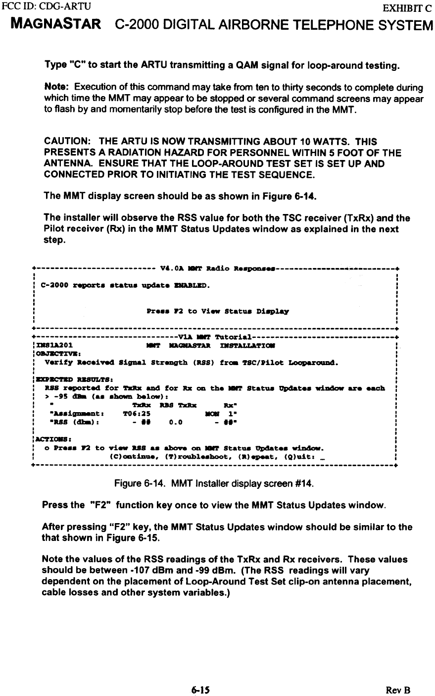
Type "C" to start the ARTU transmitting a QAM signal for loop-around testing.
Note: Execution of this command may take from ten to thirty seconds to complete during
which time the MMT may appear to be stopped or several command screens may appear
to flash by and momentarily stop before the test is configured in the MMT.
CAUTION: THE ARTU IS NOW TRANSMITTING ABOUT 10 WATTS. THIS
PRESENTS A RADIATION HAZARD FOR PERSONNEL WITHIN 5 FOOT OF THE
ANTENNA. ENSURE THAT THE LOOP-AROUND TEST SET IS SET UP AND
CONNECTED PRIOR TO INITIATING THE TEST SEQUENCE.
The MMT display screen should be as shown in Figure 6-14.
The installer will observe the RSS value for both the TSC receiver (TxRx) and the
Pilot receiver (Rx) in the MMT Status Updates window as explained in the next
step.
+ V&.OA MMT Radio ...~ +
I I
I I
: C-2000 report. .tatu. update BRABLZD. :
I I
I I
I I
I I
: Pr... P2 to Vi.. Statua ni8P~ :
I I
I I
+ +
+ ~.-T Tutorial +
: XR81A201 .-T HAl8ASTU m8'rALLA.'1'%~ :
:~: :
: V.rify aeceiv.4 SigDal Strength (US) fr~ '1'SC/Pilot ~. :
I I
I I
:DP~ USUL'1'S: :
: US reported for TxRx aJI4 for ... on the ~ Statua Updat.. wiaaow are .ach :
: > -95 dBa (.. .~ below): :
: - TxRx US TxRx :
: -A8.igD88Dt: '1'06:25 MOR 1" :
: -US (dba): - II 0.0 - II- :
I I
I I
:AC'1'%C88: :
: 0 Pr... r2 to vi- US a. above OD 8'J' Statua Q»dat.. w!D4OIf. :
: (C)oatiDue. ('1')roubl..hoot. (a)epeat. (Q)u!t: - :
+ +
Figure 6-14. MMT Installer display screen #14.
Press the "F2" function key once to view the MMT Status Updates window.
After pressing "F2" key, the MMT Status Updates window should be similar to the
that shown in Figure 6-15.
Note the values of the RSS readings of the TxRx and Rx receivers. These values
should be between -107 dam and -99 demo (The RSS readings will vary
dependent on the placement of Loop-Around Test Set clip-on antenna placement,
cable losses and other system variables.)
6-1S RevB
FCC ID: CDG-ARTU
MAGNASTAR
EXHIBIT C
C-2000 DIGITAL AIRBORNE TELEPHONE SYSTEM
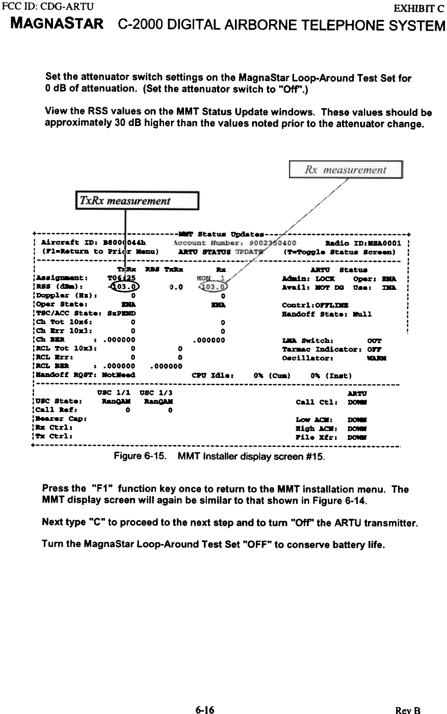
Set the attenuator switch settings on the MagnaStar Loop-Around Test Set for
0 dB of attenuation. (Set the attenuator switch to .'Off".)
View the RSS values on the MMT Status Update windows. These values should be
approximately 30 dB higher than the values noted prior to the attenuator change.
Rx measurement
+
"dio xD..aOOOl :
(~l.. StatU8 ScreeD) :
I
I
Aa'rO Stat- :
Ad8iD : LOCK Oper . aA. :
ATaJ.l.: 8OT DQ v... ma. :
I
I
CODtrl..OrI'LXD :
Rando!! Stat.: ~l. :
I
I
!
0.0
+ ~ S~a~U8 upaa~ : Aircraf~ XD: B800( 064h
: (Pl.bturn ~o Prj,c,r Menu) U'rU ftATUS
' ,
: 'l'2 :Rx RBS ~ Rx
:A8.i~~: 'r~
:US (~): ~
:Doppl.r (8s): 0 0
:Oper Sta~., BRA BRA
:'1'SC/ACC S~a~.: SsPOD
: Ch 'l'o~ lOx': 0 0
:Ch Err 10x3: 0 0
:Ch ... : .000000 .000000 ~ 8wi~ch: OUT
: acL 'ro~ 10x3 I 0 0 ~ :rJIdica~or I on
:RCL Errl 0 0 o.cil1a~orl""
:acL'" I .000000 .000000
:B8Ddoff -oftl Bathed CPO %41.. 0% (CIa) 0% (J:II8~)
' ,
: trSC 1/1 trSC 1/3 UTU
: trSC Sta~.: RaDQAM a.DQAK Call C~l: ~
:ca11 bfl 0 0
:Bearer Capl Low AC8: ~
:Rx Ctrl, High AC8: ~
:"- Cull Pil. Xfr: ~
+ Figure 6-15. MMT Installer display screen #15.
Press the "F1" function key once to return to the MMT installation menu. The
MMT display screen will again be similar to that shown in Figure 6-14.
Next type "C" to proceed to the next step and to turn "Oft" the ARTU transmitter.
Tum the MagnaStar Loop-Around Test Set "OFF" to conserve battery life.
6-16 Rev 8
FCC ID: CDG-ARTU
MAGNASTAR
EXHIBIT C
C-2000 DIGITAL AIRBORNE TELEPHONE SYSTEM
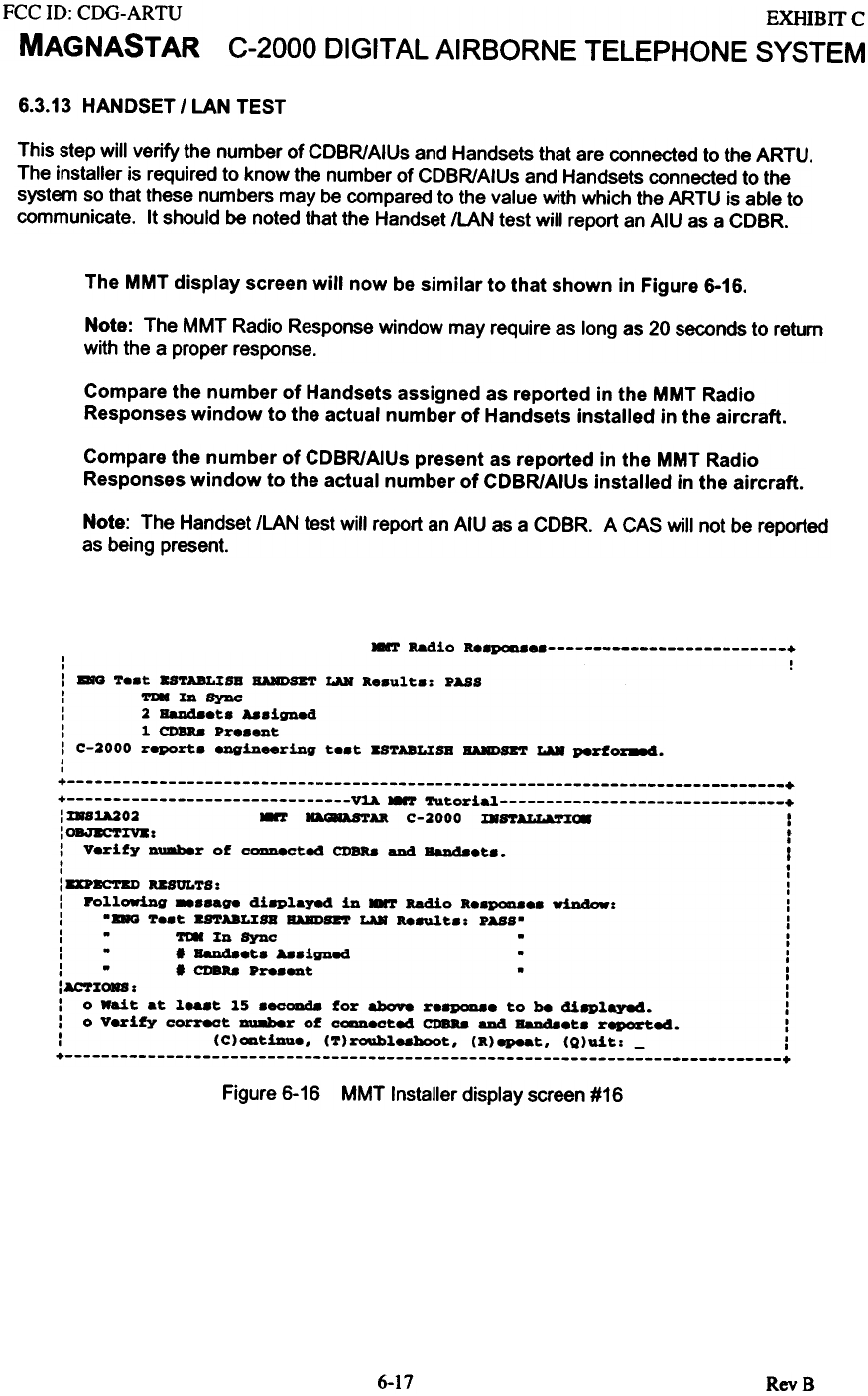
6.3.13 HANDSET I LAN TEST
This step will verify the number of CDBR/AIUs and Handsets that are connected to the ARTU.
The installer is required to know the number of CDBR/AIUs and Handsets connected to the
system so that these numbers may be compared to the value with which the ARTU is able to
communicate. It should be noted that the Handset ILAN test will report an AIU as a CDBR.
The MMT display screen will now be similar to that shown in Figure 6-16.
Note: The MMT Radio Response window may require as long as 20 seconds to return
with the a proper response.
Compare the number of Handsets assigned as reported in the MMT Radio
Responses window to the actual number of Handsets installed in the aircraft.
Compare the number of CDBR/AIUs present as reported in the MMT Radio
Responses window to the actual number of CDBR/AIUs installed in the aircraft.
Note: The Handset ILAN test will report an AIU as a COeR. A CAS will not be reported
as being present.
HMT Radio ...~ +
I I
I .
: ~ '!'e.t BSTABLXSB BARDSET LAB a..ult.. PASS
: Tl8XDSync
: 2 Ball48et. Aa8igned
: 1 CDBR.8 Pre.ent
: C-2000 report. eDgin_ring te.t BSTABLXSB BARDSET LU P8rfo~.
I
I
+ +
+ V~ ~ Tutoria~ +
: %881A202 ~ ~AK C-2000 mftALL&S':EI* I
: OBJBCT%V8 : f
: V.rify Duaber of CoaDeCted CDBa8 aDd BaJI48.t.. I
I I
I I
: DP8corBI) USULTS: :
: Po~~owiDg -.-ge di8P~ayed in 8'r Radio R..pQD8.. window: :
: -DO T..t U'1'ABL%8B BARDSB'l' LAB "8U~t.: PASS- :
: - 'rI8 %0 Sync - :
: - . BaJI48.t. A8.igned - :
: - . CDBa8 Pre._t - :
:~%ORS: :
: 0 Wait at ~...t ~5 .ec0Dd8 for abO98 r.8p0n8. to be di8P~aye4. :
: 0 Verify correct DU8ber of c-.cted CDBa8 aDd BaJI48.t. r~e4. :
: (C)ODt!Da., (T)roub~e8hoot, (R)epeat, (Q)uit: - :
+ +
Figure 6-16 MMT Installer display screen #16
6-17 RevB
FCC ill: CDG-ARTU
MAGNASTAR
EXHIBU C
C-2000 DIGITAL AIRBORNE TELEPHONE SYSTEM
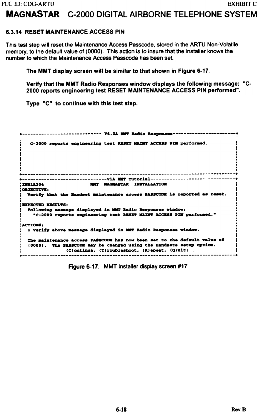
6.3.14 RESET MAINTENANCE ACCESS PIN
This test step will reset the Maintenance Access Passcode, stored in the ARTU Non-Volatile
memory, to the default value of (0000). This action is to insure that the installer knows the
number to which the Maintenance Access Passcode has been set.
The MMT display screen will be similar to that shown in Figure 6-17.
Verify that the MMT Radio Responses window displays the following message: "C-
2000 reports engineering test RESET MAINTENANCE ACCESS PIN performed".
Type "C" to continue with this test step.
+ V..O&.-T Ba4io ".poaa +
i C-2000 report. eDQ'iDeeriDG t_t a8n'r DIft ACC888 pm perfo~. :
I .
I .
I I
I I
I I
I I
I .
I .
I .
I I
+ +
+ ~ -.r Tutorial +
: %881A206 .., ~U :E88'rALLA.n.. :
:C8.I~-T~Y.1 :
: Verify that tha 8aDd8.t _iDt_. aO088. p~ i. reporte4 -~. :
I I
I I
: 8DBC'1'8D U8ULT8 I :
: rollowing _..ag. 41aplayed in .., aadio bapcma.. wiDdow: :
: .C-2000 report. engiDeeriDG t..t usn D%8T ACC888 pm perf~.. !
I '
I I
:AC'r:E~1 :
: 0 vez1fy ahoY8 _..&g8 418Pl&yed 111. ~ b410 h~.. wiDdow. :
I I
I I
: 'rh8 _1II.t- &co... PUSCOI8 ba8 - heeD ..t to the default Yalu. of :
: (0000). 'rh8 P~8CO18 -y be chaDge4 u.1Dg th. BaD48.t. ..tup Qpt1oa. :
: (C)ODt1Du., (~)roubl.8boot, (.)~t, (Q)u1tl - :
+ +
Figure 6-17. MMT Installer display screen #17
RevS
6-18
FCC ill: CDG-ARTU
MAGNASTAR
EXHIBITC
C-2000 DIGITAL AIRBORNE TELEPHONE SYSTEM
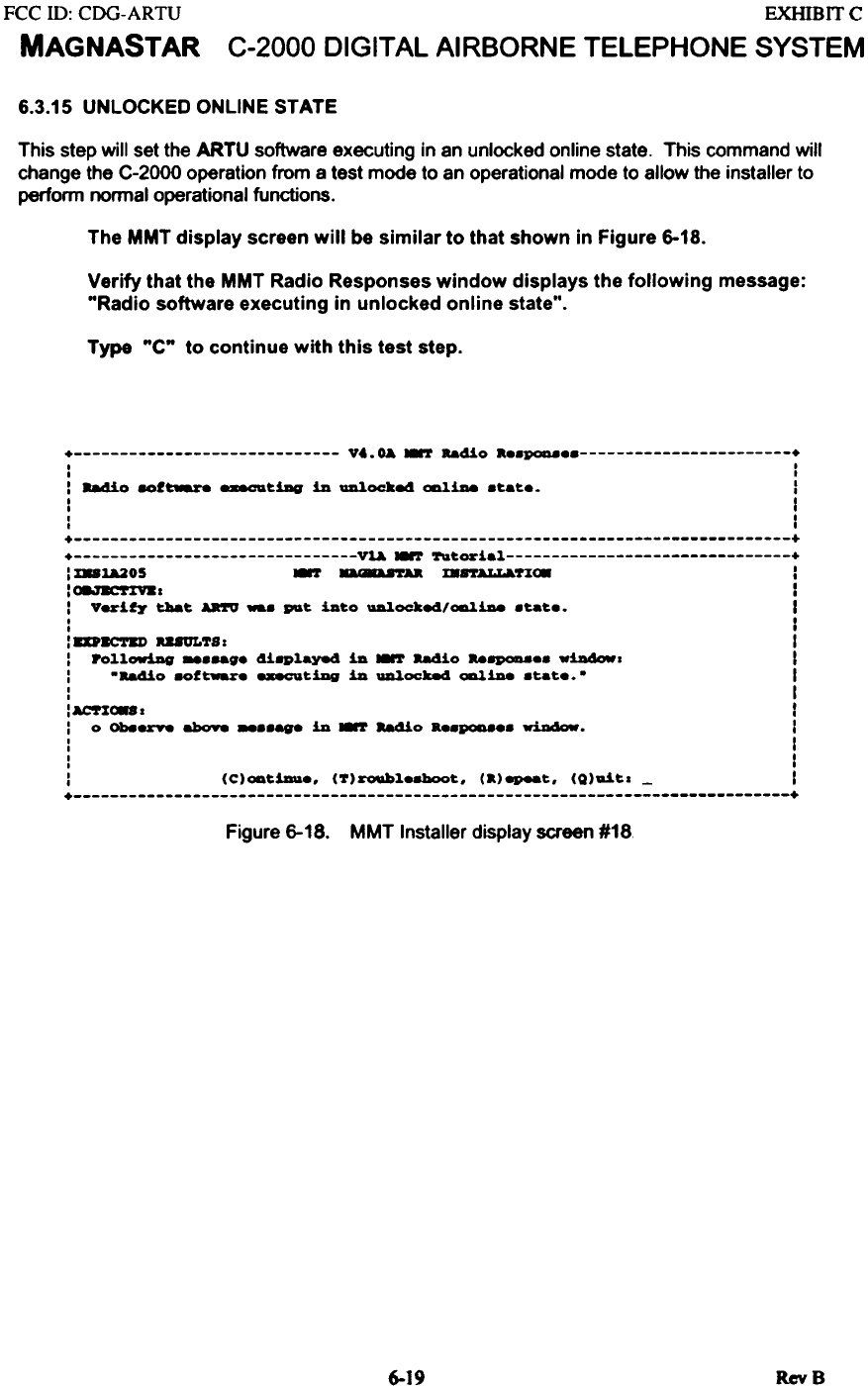
6.3.15 UNLOCKED ONLINE STATE
This step will set the ARTU software executing in an unlocked online state. This command will
change the C-2000 operation from a test mode to an operational mode to allow the installer to
perform normal operational functions.
The MMT display screen will be similar to that shown in Figure 6-18.
Verify that the MMT Radio Responses window displays the following message:
"Radio software executing in unlocked online state".
Type "C" to continue with this test step.
+ V..~ ~ Ra410 a..~ +
I I
I I
I 884io 8Of~ _tillg in ~oc:ke4 ~1De .tat.. I
I I
I I
I I
+ +
+ Vl& ~ Tutorial +
: %81&205 ~ a8U'rAa mrrALLa.UC8 I
I~~-T%Y.I I
: Verity t:!Iat AR'fV -. Pl&t into ~oc:ke4/~1De .tat.. I
I I
I I
: 8D8C'1'81) U8ULTS: I
: PolloriAg _..ag. 4i8Played in ~ Radio Ra8P0D8.. Willdowl I
: -Ra4io 8Of~. _tiDg in ~0cke4 ~1De .tat.. - I
: I
: ACT%C88 I I
: 0 ON8rY8 abo98 -..age in ~ Ra4io a..~.. ~. I
: I
: I
: (C)oatiDu., (7)roubl.8boot, (a)epeat, (Q)ait. - I
+ +
Figure 6-18. MMT Installer display screen #18.
RevB
6-19
EXHIBffC
C-2000 DIGITAL AIRBORNE TELEPHONE SYSTEM
FCC ill: CDG-ARTU
MAGNASTAR
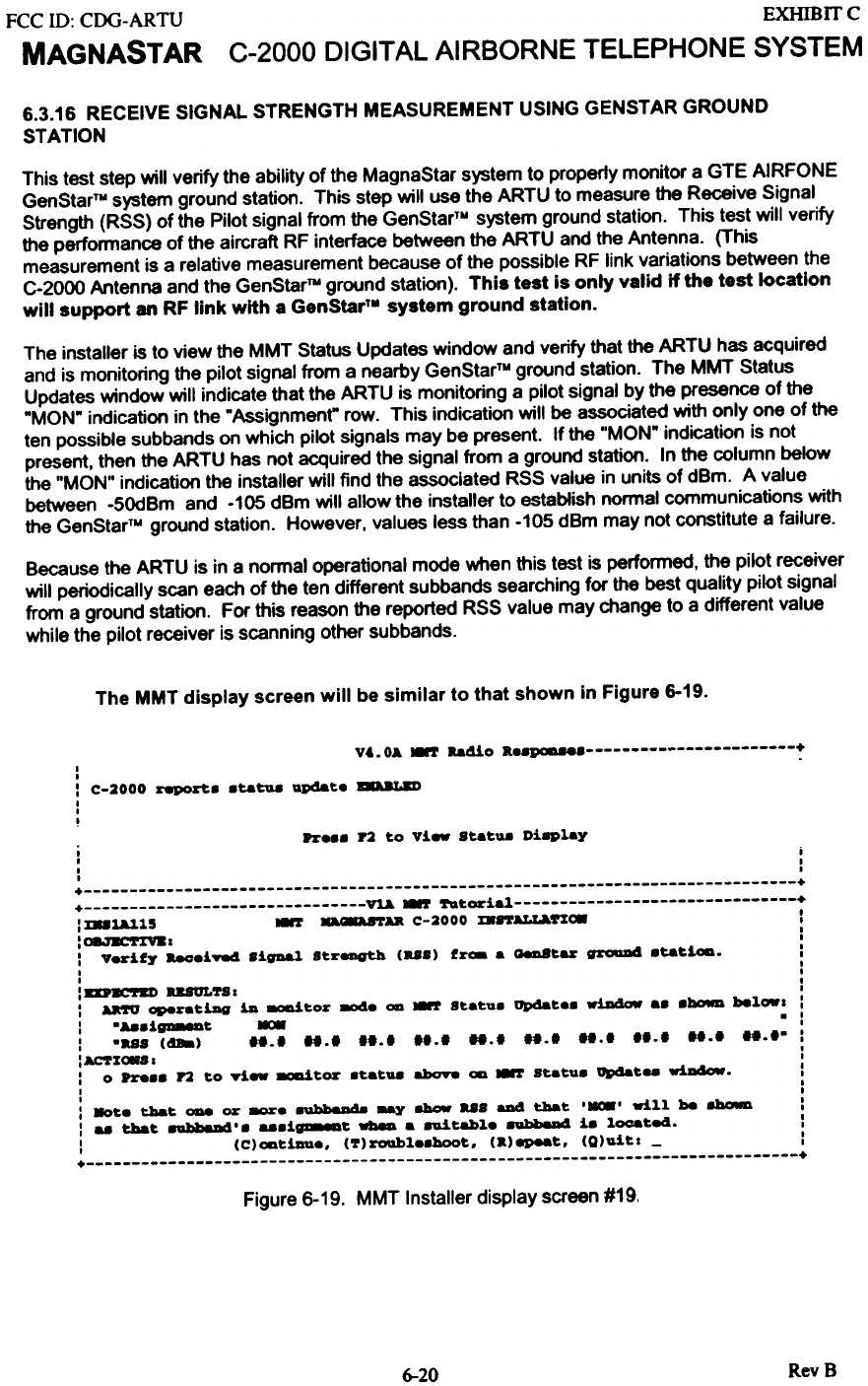
6.3.16 RECEIVE SIGNAL STRENGTH MEASUREMENT USING GENSTAR GROUND
STATION
This test step will verify the ability of the MagnaStar system to properly monitor a GTE AIRFONE
GenStarTU system ground station. This step will use the ARTU to measure the Receive Signal
Strength (RSS) of the Pilot signal from the GenStarTM system ground station. This test will verify
the performance of the aircraft RF interface between the ARTU and the Antenna. (This
measurement is a relative measurement because of the possible RF link variations between the
C-2000 Antenna and the GenStarTU ground station). This test is only valid if the test location
will support an RF link with a GenStarTM system ground station.
The installer is to view the MMT Status Updates window and verify that the ARTU has acquired
and is monitoring the pilot signal from a nearby GenStarN ground station. The MMT Status
Updates window will indicate that the ARTU is monitoring a pilot signal by the presence of the
"MON" indication in the "Assignment" row. This indication will be associated with only one of the
ten possible subbands on which pilot signals may be present. If the "MON" indication is not
present, then the ARTU has not acquired the signal from a ground station. In the column below
the "MON" indication the installer will find the associated RSS value in units of demo A value
between -5OdBm and -105 dBm will allow the installer to establish normal communications with
the GenStarTM ground station. However, values less than -105 dBm may not constitute a failure.
Because the ARTU is in a normal operational mode when this test is performed. the pilot receiver
will periodically scan each of the ten different subbands searching for the best quality pilot signal
from a ground station. For this reason the reported RSS value may change to a different value
while the pilot receiver is scanning other subbands.
The MMT display screen will be similar to that shown in Figure 6-19.
V&.OA ~ ..410 a..paD8e ~
I
I
: C-2000 ~Z't8 8tatua update 8A.~-8D
I
I
!Pr... P2 to vi- sut- Diaplay
,
, i
, '
, I
+ +
+ ~ ~ ~~ori.l +
: %DUllS ~ D8AftU C-2000 m8'1'Al.l,A.n~ :
"(8.,~-T~Y.1 I
I I
: Verify ~.iY84 .igDal S~reDQth (U.) f~. 08D8~ar grcRaDII .ta~iC8. :
I I
I I
:DP~-Tau USUL7S1 :
: U'fU ~r.~iJIQ iD ~~or 8)d. ~ ~ S~.~u. opcSa~.. wiDdOIf .. .~ bel~1 :
I .A8.i~~ - . :
: ."S (dBa) 11.1 1t.1 11.1 11.1 1t.1 11.1 1t.1 11.1 1t.1 11.1. :
:Acor%~SI :
: 0 Pr8.. r2 ~o yi- ~t.or .~.~U8 aboY8 ~ ~ S~.~U. opcSa~.. wiadow. :
I I
I I
: 80~. t:ba~ - or ~. ..~~Dd. ~ 8hCJW u. aDd t:ba~ ,-, .ill be 8bo.D :
: .. t:ba~ 8abb8M'. ...1~~ -- . 8Uitabl. 8abb8M i. loca~e4. :
: (C)~~iDD.. (7)roubl..hoot.. (a)epeat.. (Q)ui~1 - :
+ +
Figure 6-19. MMT Installer display screen #19.
RevB
6-20
FCC ill: CDG-ARTU
MAGNASTAR
EXHIBIT C
C-2000 DIGITAL AIRBORNE TELEPHONE SYSTEM
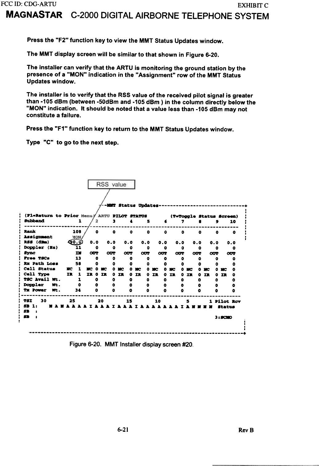
Press the "F2" function key to view the MMT Status Updates window.
The MMT display screen will be similar to that shown in Figure 6-20.
The installer can verify that the ARTU is monitoring the ground station by the
presence of a "MON" indication in the "Assignment" row of the MMT Status
Updates window.
The installer is to verify that the RSS value of the received pilot signal is greater
than -105 dBm (between -50dBm and -105 dBm) in the column directly below the
"MON" indication. It should be noted that a value less than -105 dBm may not
constitute a failure.
Press the "F1" function key to return to the MMT Status Updates window.
Type "C" to go to the next step.
RSS value
-~ Statu. Q»dat +
I
I
P%I.o'r ftATUS ('r-'ron1. Stat- 8ea"..o) :
3 6 5 , 1 8 , 10 :
I
I
000000000: I
I
.(9}o.o)
: (P3..bturn to ~ior
:8IIhbaDd 3.
I
, : RaIIk 3.08
: A8.i~t
: ass (488) ---' 0.0 0.0 0.0 0.0 0.0 0.0 0.0 0.0 0.0
: Doppler (B8) 3.3. 0 0 0 0 0 0 0 0 0
: 8YDe m 00'r 0U'1' 0U'1' 0U'1' 0U'1' 0U'1' 0U'1' 0U'1' 00'r
: Pree TSC. 3.3 0 0 0 0 0 0 0 0 0
: .. Path Lo8. 58 0 0 0 0 0 0 0 0 0
: Cell Stat- ~ 3. 8C 0 8C 0 8C 0.: 0.: 0.: 0.: 0': 0': 0
: Cell Type xa 3. nOD 0 non 0 xa 0 noxa 0 D 0 D 0
: TSC A?ail Wt. 3. 0 0 0 0 0 0 0 0 0
: Doppler .t. 0 0 0 0 0 0 0 0 0 0
: TX Power Wt. 3. 0 0 0 0 0 0 0 0 0
,
, : ~sx 30 25 20 3.5 3.0 5 3. Pilot aav
: SB 3.: . A . A A A A X A A A X A A A X A A A A A A A X A . . .. 8tat1l8
: S8 :
:.. : 3:~
, i
. ,
I
I
+
Figure 6-20. MMT Installer display screen #20.
6-21 RevB
FCC ID: CDG-ARTU
MAGNASTAR EXHIB IT C
C-2000 DIGITAL AIRBORNE TELEPHONE SYSTEM
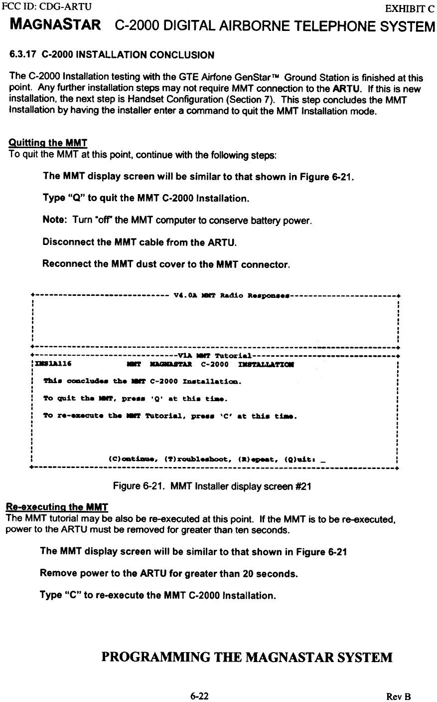
6.3.17 C-2000 INSTALLATION CONCLUSION
The C-2000 Installation testing with the GTE Airfone GenStarTM Ground Station is finished at this
point. Any further installation steps may not require MMT connection to the ARTU. If this is new
installation, the next step is Handset Configuration (Section 7). This step concludes the MMT
Installation by having the installer enter a command to quit the MMT Installation mode.
Quitting the MMT
To quit the MMT at this point. continue with the following steps:
The MMT display screen will be similar to that shown in Figure 6-21.
Type "Q" to quit the MMT C-2000 Installation.
Note: Turn "off'the MMT computer to conserve battery power.
Disconnect the MMT cable from the ARTU.
Reconnect the MMT dust cover to the MMT connector.
+ Vt.OA -.T Radio R..POD +
I I
I I
I I
I I
I ,
I ,
I I
I I
I I
I I
+ +
+ VlA ~ Tutorial +
: D8~]" 8'r orB C-2000 ~~ :
I I
I I
: ~. CODclude. the 8'r C-2000 XD8ta11atiOD. :
I I
I I
: To QDit the MNT, pr... '0' at thi. t!8e. :
I I
I I
: To r.-_cut. the 8'r Tutorial, pre.. 'c' at thi. t~. :
I I
I I
I I
I I
I I
I I
I I
I I
: (C)ODtiau8, (7)roQbl..boot, (a)epeat, (Q).t~1 - :
+ +
Figure 6-21. MMT Installer display screen #21
Re-executina the MMT
The MMT tutorial may be also be re-executed at this point. If the MMT is to be re-executed,
power to the ARTU must be removed for greater than ten seconds.
The MMT display screen will be similar to that shown in Figure 6.21
Remove power to the ARTU for greater than 20 seconds.
Type "C" to re-execute the MMT C-2000 Installation.
PROGRAMMING THE MAGNAST AR SYSTEM
6-22 RevS
FCC ill: CDG-ARTU
MAGNASTAR
EXHIBIT C
C-2000 DIGITAL AIRBORNE TELEPHONE SYSTEM
7-1
7-1
7-1
7-S
7-S
7-S
...7-6
...7-6
...7-7
...7-7
...7-8
...7-9
.7-10
.7-10
.7-11
.7-11
.1-12
.7-12
.7-12
.1-13
.7-13
.7-1S
.7-1S
.7-16
.1-16
.7-16
.7-17
.7-18
.7-18
.7-19
.7-19
.7-20
.7-20
,7-21
7-21
7-22
7-23
7-23
7-23
7-23
7-2S
7-25
7-26
7.0 PROGRAMMING THE MAGNASTAR SYSTEM 7.1 HANDSET CONFIGURATION SCREENS
7.1.1 CONFIGURATION SCREEN FLOW CHART 7.1.2 DETAILED CONFIGURATION SCREENS 7.1.2.1 Services Screen .".'."""""""""""""""""""""'...' 7.1.2.2 Main Menu 7.1.2.3 Checking Handset Setup Information Screens 7.1.2.4 Starting a Maintenance Session 7.1.2.5 Maintenance Screen #1 7.1.2.5.1 Changing the Passcode and Billing Mode 7.1.2.5.2 Inplane Numbers 7.1.2.5.3 Aircall Numbers 7.1.2.5.3.1 Disabling a Handset From Ringing with an Aircraft Aircall Number 7.1.2.5.3.2 Direct Call Pickup 7.1.2.5.4 SA TCOM TerminallD's 7.1.2.5.4.1 Disabling a Station From Ringing with a SATCOM Aircraft TerminallD
7.1.2.5.5 Call Waiting 7.1.2.5.6 Speed Dial 7.1.2.5.7 AIU Configuration - SATCOM 7.1.2.5.8 AIU Configuration - HF Radio 7.1.2.6 Maintenance Screen #2 7.1.2.6.1 Station Setup ,
7.1.2.6.2 Select Aero-H or Aero-l SATCOM Service ,
7.1.2.6.3 Ringer Enable/Disable ,
7.1.2.6.4 Dialing Plan 7.1.2.6.5 Default Link and Auto Link Switch 7.1.2.6.6 Service Availability and Call In Progress Indicators 7.1.2.6.7 MODEM Settings 7.1.2.6.8 Handset Attributes 7.1.2.7.1 Handset Alerter and RJ-l1 Gain Settings 7.1.2.7.2 Auxiliary Call Alerter and Auxiliary Call Alerter Cadence 7.1.2.7.3 Speaker Gain: 7.1.2.7.4 LED Blink Rates 7.1.2.7.5 Sidetone Gains. 7.1.2.7.6 Autodial DTMF Monitor 7.1.2.7.7 Microphone TX Gain 7.1.2.8 Aircall Screens , 7.1.2.8.1 Personal Aircall Number Register 7.1.2.8.2 Viewing Stored Aircall Numbers (Messages) 7.1.2.8.3 Viewing Programmed Aircall and SATCOM TerminallD Numbers 7.1.2.9 Remote Station Programming.. 7.1.2.10 CDBR-2 Station Setup 7.2 AIRCRAFT CONFIGURATION SHEET
7-i RevB