Raytheon IIS ARTU Air-Ground Radio System User Manual installation manual part three
Raytheon Company Air-Ground Radio System installation manual part three
Contents
installation manual part three
FCC ill: CDG-ARTU
MAGNASTAR
EXHIBITC
C-2000 DIGITAL AIRBORNE TELEPHONE SYSTEM
7.0 PROGRAMMING THE MAGNAST AR SYSTEM
7.1 HANDSET CONFIGURATION SCREENS
This section provides detailed information in support of the C-2000 user guide to help the installer with the configuration
programming of the MagnaStar system Included in this section are a flow chart of the maintenance set-up screens and
descriptions of the handset set-up screens. These screens apply to ARTU software version ARTCC40B.
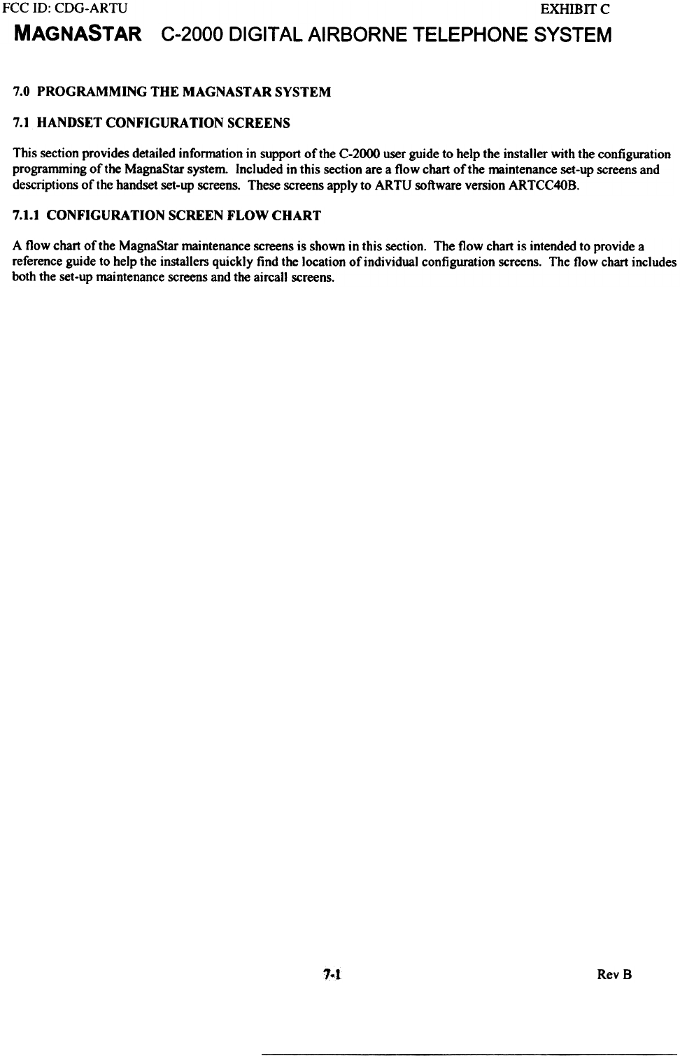
7.1.1 CONFIGURATION SCREEN FLOW CHART
A flow chart of the MagnaStar maintenance screens is shown in this section. The flow chart is intended to provide a
reference guide to help the installers quickly find the location of individual configuration screens. The flow chart includes
both the set-up maintenance screens and the airca]] screens.
1.1 RevS
FCC ID: CDG-ARTU
MAGNASTAR
EXHIBIT C
C-2000 DIGITAL AI RBORNE TELEPHONE SYSTEM
-4 Phone # I
6
AlU
Ring Handset wI
Aircraft Call
DIsable PTT
Decay
Sense
L: Label
+
4, Call Waiting
14 RevS
FCC ID: CDG-ARTU
MAGNASTAR
EXHIBUC
C-2000 DIGITAL AIRBORNE TELEPHONE SYSTEM
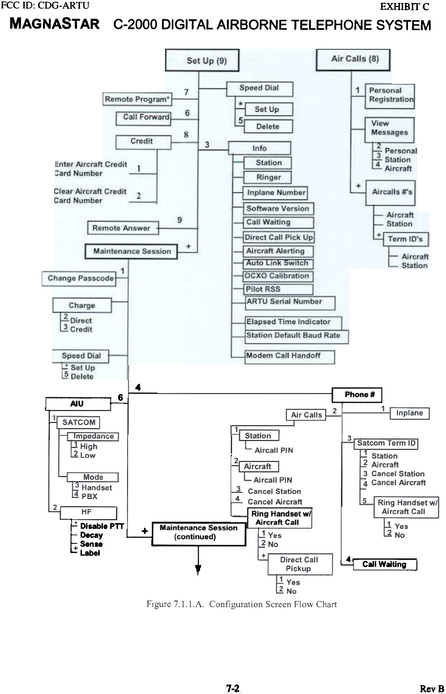
Figure 7. .8. Configuration Screen Flow Chart con't.
70.:3 Rev 8
FCC 10: CDG-ARTU
MAGNASTAR
EXHIBIT C
C-2000 DIGITAL AIRBORNE TELEPHONE SYSTEM
L--t Remote Station Assigned
I Main~n..ce I
1
Station Set Up I
S18tIon I
1 Cockpit
2 Coin
Uplink I
3 Voice
4 Fax
5TDO
*
4 5
+
r~;~~all Alerter I
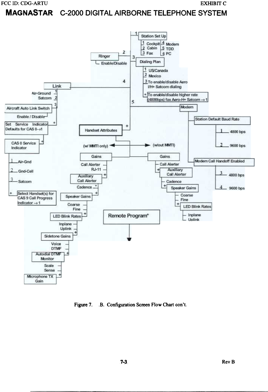
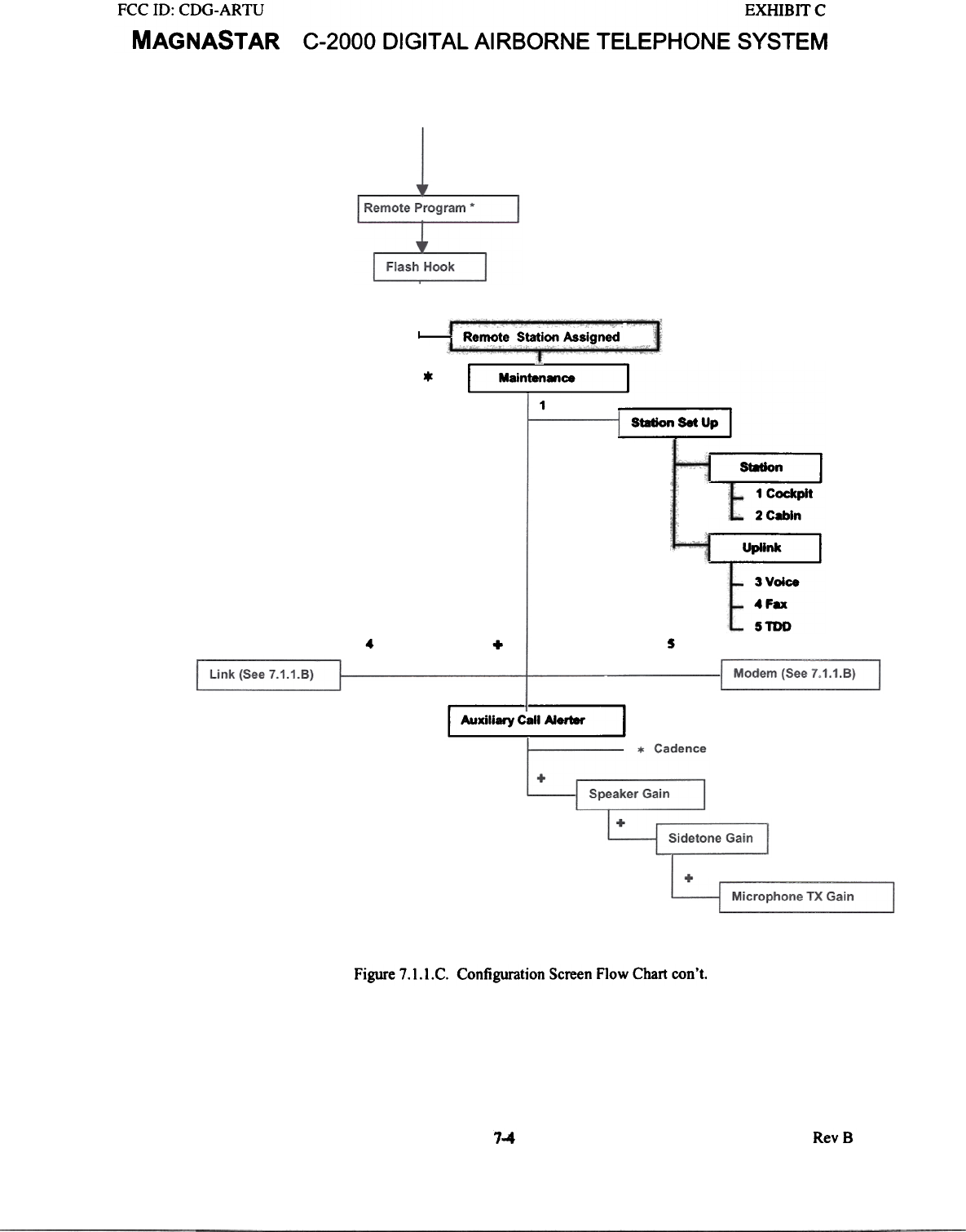
Figure 7.1.I.C. Configuration Screen Flow Chart con't.
7-4 RevS
FCC ID: CDG-ARTU
MAGNASTAR
EXHIBIT C
C-2000 DIGITAL AIRBORNE TELEPHONE SYSTEM
7.1.2 DETAILED CONFIGURATION SCREENS
The following section provides information about the individual configuration screens. This section is intended to provide
the installer with a visual reference to the configuration screens and is supplemental information to the user guide. However
it is not intended as a replacement for the user guide.
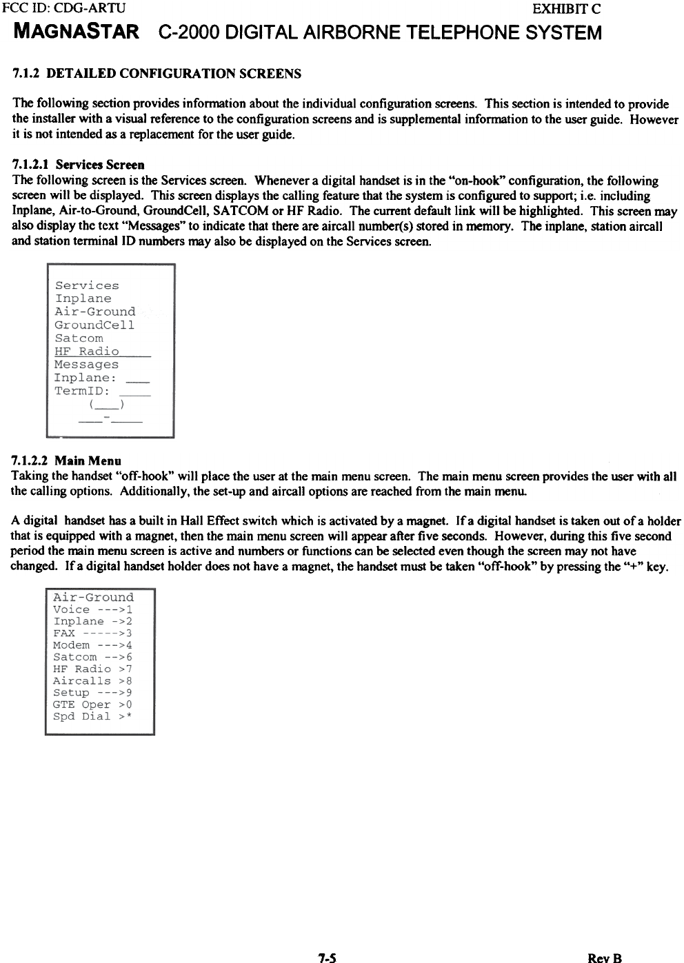
7.1.2.1 Services Screen
The following screen is the Services screen. Whenever a digital handset is in the "on-hook" configuration, the following
screen will be displayed. This screen displays the calling feature that the system is configured to support; i.e. including
Inplane, Air-to-Ground, GroundCeIl, SATCOM or HF Radio. The current default link will be highlighted. This screen may
also display thc tcxt "Messages" to indicate that there are aircall number(s) stored in memory. The inplane, Station aircall
and station terminal ID numbers may also be displayed on the Services screen.
7.1.2.2 Main Menu
Taking the handset "off-hook" will place the user at the main menu screen. The main menu screen provides the user with all
the calling options. Additionally, the set-up and aircall options are reached from the main menu.
A digital handset has a built in Hall Effect switch which is activated by a magnet. If a digital handset is taken out of a holder
that is equipped with a magnet, then the main menu screen will appear after five seconds. However, during this five second
period the main menu screen is active and numbers or functions can be selected even though the screen may not have
changed. If a digital handset holder does not have a magnet, the handset must be taken "off-hook" by pressing the "+" key.
7-5 RevB
FCC ID: CDG-ARTU
MAGNASTAR EXHmIT C
C-2000 DIGITAL AIRBORNE TELEPHONE SYSTEM
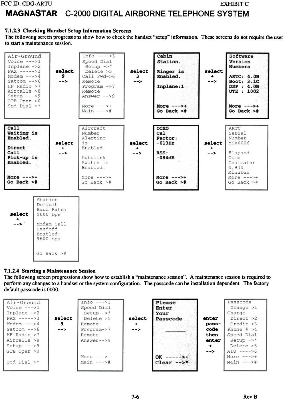
7.1.2.3 Checking Handset Setup Information Screens
The following screen progressions show how to check the handset "setup" information. These screens do not require the user
to start a maintenance session.
Cabin
Station Software
Version
Numbers
.elect
9
-->
Ringer is
Enabled. select
+
-->
select
3
--> ARTC
Boot
DSP
UTE
4o0B
3o1C
4o0B
1002
Inplane:l
More --->+
Go Back >t
More --->+
Go Back >t
OCXO
Cal
Factor
-0138z
Call
Waiting is
Enabled. select
+
-->
select
+
-->
select
+
-->
Direct
Call
Pick-up is
Enabled .
RSS:
-O84dB
More --->+
Go Back >t
More --->+
Go Back >t
select
+
-->
7.1.2.4 Starting a Maintenance Session
The following screen progressions show how to establish a "maintenance session". A maintenance session is required to
perfonn any changes to a handset or the system configuration. The passcode can be installation dependent. The factory
default passcode is 0000.
Please
Enter
Your
Passcode
select
9
-->
select
+
-->
enter
pass-
code
then
enter
+
-->
OK >+
Clear -->!
7-6 RevB
FCC ID: CDG-ARTU
MAGNASTAR
EXHIBITC
C-2000 DIGITAL AIRBORNE TELEPHONE SYSTEM
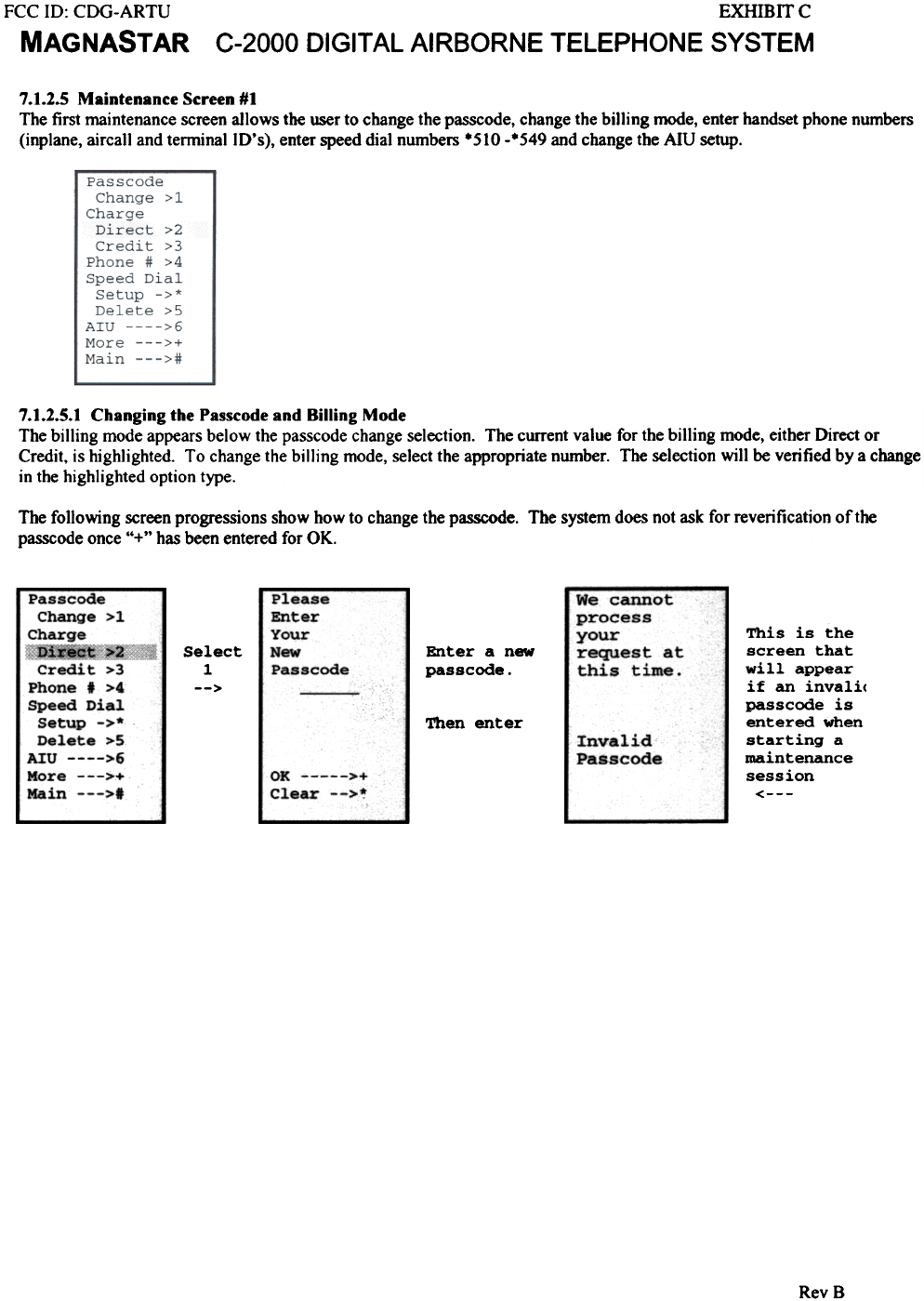
7.1.2.5 Maintenance Screen #1
The first maintenance screen allows the user to change the passcode, change the bi11ing mode, enter handset phone numbers
(inplane, aircall and terminal 10's), enter speed dial numbers .510 -.549 and change the AIU setup.
7.1.2.5.1 Changing the Passcode and Billing Mode
The billing mode appears below the passcode change selection. The current value for the billing mode, either Direct or
Credit. is highlighted. To change the billing mode, select the appropriate number. The selection will be verified by a change
in the highlighted option type.
The following screen progressions show how to change the passcode. The system does not ask for reverification of the
passcode once "+" has been entered for OK.
This is the
screen that
will appear
if an invali<
passcode is
entered when
starting a
maintenance
session
<---
Passcode
Change >1
Charge
~i~
Credit >3
Phone I >4
Speed Dial
Setup ->*
Delete >5
nu >6
More --->+
Main --->1
Select
1
-->
Enter a new
passcode.
We Co
proc'
your
requo
this
Please
Enter
Your
New
passcode
Then enter Invalid
Passcode
OK >+
Clear -->*
RevB
annat
ess
est at
time.
FCC ID: CDG-ARTU
MAGNASTAR
EXHIBITC
C-2000 DIGITAL AIRBORNE TELEPHONE SYSTEM
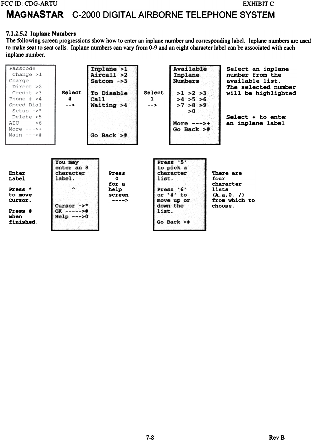
7.1.2.5.2 (nplane Numbers
The following screen progressions show how to enter an inplane number and corresponding label. Inplane numbers are used
to make seat to seat calls. Inplane numbers can vary from 0-9 and an eight character label can be associated with each
inplane number.
Inplane >1
Aircall >2
Satcom ->3
Available
Inplane
Numbers
Select an inplane
number from the
available list.
The selected number
will be highlighted
>1 >2 >3
>4 >5 >6
>7 >8 >9
>0
Select
4
-->
Select
1
--:>
To Disable
Call
Waiting >4
Select + to ente:
an inplane label
More --->+
Go Back >1
Go Back >.
Press-'S'
to pick a
character
list.
You may
enter an 8
character
label.
Enter
Label Press
0
for a
help
screen>
Press '6'
or '4' to
move up or
down the
list.
Press *
to move
cursor.
There are
four
character
lists
(A, a, 0, / )
from which to
choose.
cursor ->*
OK >t
Help --->0
Press'
when
finished Go Back >t
RevS7-8
FCC ill: CDG-ARTU
MAGNASTAR
EXHIBITC
C-2000 DIGITAL AIRBORNE TELEPHONE SYSTEM
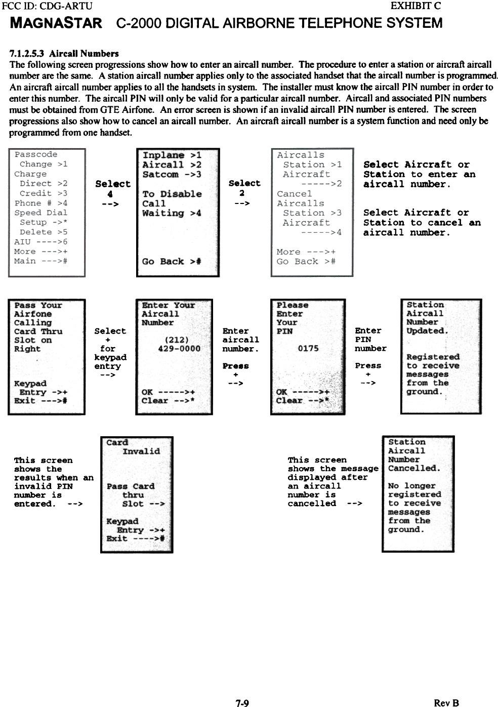
7.1.2.5.3 Aircall Numben
The following screen progressions show how to enter an aircall number. The procedure to enter a station or aircraft aircall
number are the same. A station aircall number applies only to the associated handset that the aircall number is programmed.
An aircraft aircall number applies to all the handsets in system The installer must know the aircall PIN number in order to
enter this number. The aircall PIN will only be valid for a particular aircail number. Aircall and associated PIN numbers
must be obtained from GTE Airfone. An error screen is shown if an invalid aircall PIN number is entered. The screen
progressions also show how to cancel an aircall number. An aircraft aircall number is a system function and need only be
programmed from one handset.
Inplane-;;:- i
Aircall >2
Satcom ->3 Select Aircraft or
Station to enter an
aircall number.
Select
4
-->
Select
2
-->
Select Aircraft or
Station to cancel an
aircall number.
To Disable
Call
Waiting >4
Go Back >t
Please
Enter
Your
PIN
Station
Aircall
Number
Updated.
Pass Your
Airfone
Calling
Card Thru
Slot on
RiQ'ht
~terYour
Aircall
Number Enter
PIN
number
Select
+
for
keypad
entry
-->
Enter
aircall
number.
(212)
429-0000 0175 Registered
to receive
messages
from the
ground.
Pr..s
+
-->
Press
+
-->
~.ypad
Entry ->+
Exit --->t 01: >+
c1.ear -->*
OK >+
Clear -->*
Station
Aircall
Number
Cancelled
Card
Invalid
This screen
shows the
results when an
invalid PIN
number is
entered. -->
This screen
shows the message
displayed after
an aircall
number is
cancelled -->
No longer
registered
to receive
messages
from the
ground.
Pass Card
thru
Slot -->
Keypad
Bntry ->+
Bxit >f
7-9 RevB
FCC ill: CDG-ARTU
MAGNASTAR
EXHffiIT C
C-2000 DIGITAL AIRBORNE TELEPHONE SYSTEM
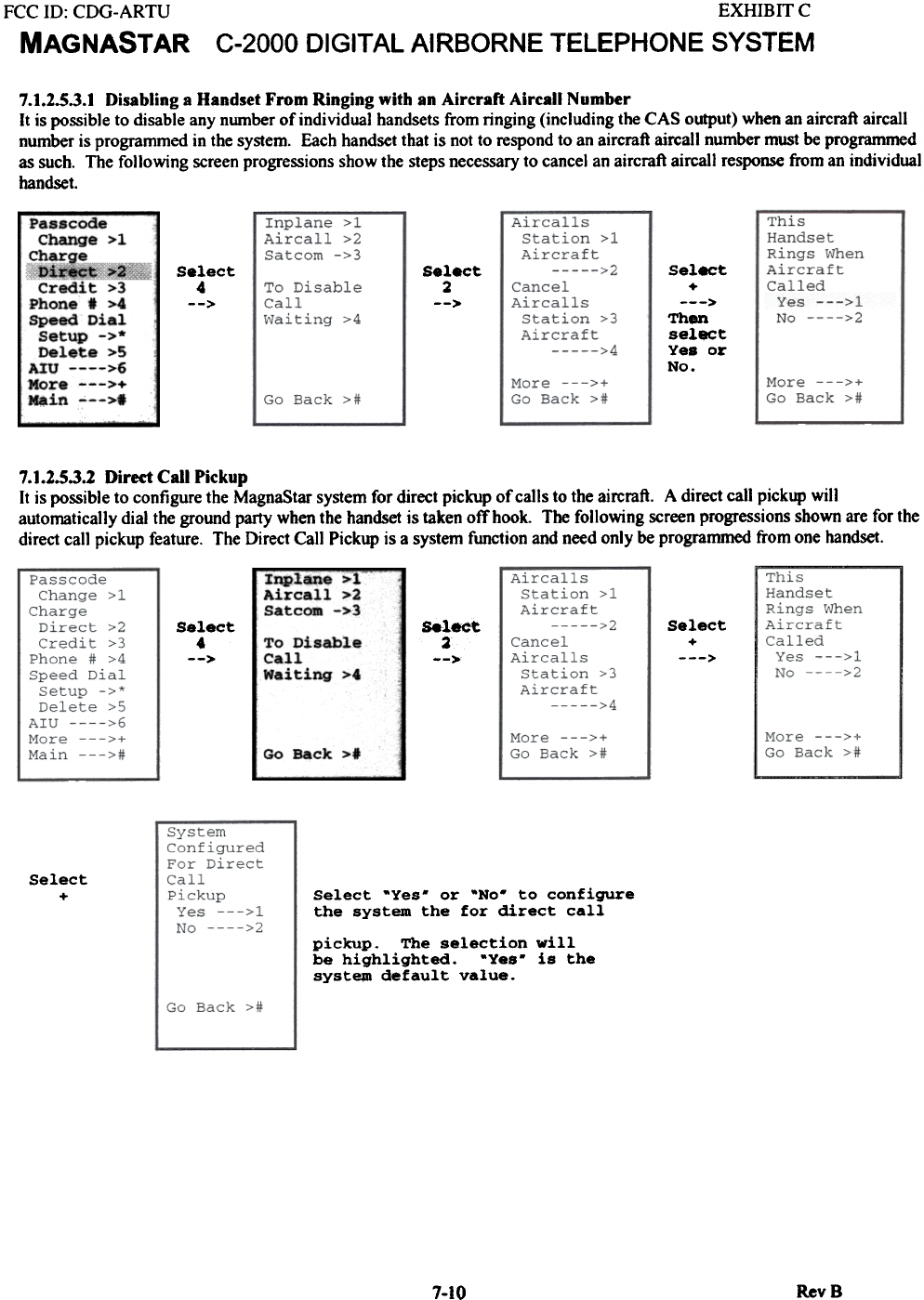
7.1.2.5.3.1 Disabling a Handset From Ringing with an Aircraft Aircall Number
It is possible to disable any nwnber of individual handsets from ringing (including the CAS output) when an aircraft aircall
nwnber is prograrnrned in the system. Each handset that is not to respond to an aircraft aircall number must be programmed
as such. The following screen progressions show the steps necessary to cancel an aircraft aircall response from an individual
handset.
Passc-o~
Change >1
charge
n~?!J
Credit >3
Phone' >4
Speed Dial
Setup ->*
Delete >5
AIU >6
More --->+
.in --->.
5e
Th
se
Ye
No
Select
4
-->
select
2
-->
7.1.2.5.3.2 Direct Call Pickup
It is possible to configure the MagnaStar system for direct pickup of calls to the aircraft. A direct call pickup will
automatically dial the ground party when the handset is taken off hook. The following screen progressions shown are for the
direct call pickup feature. The Direct Call Pickup is a system function and need only be programmed from one handset.
Inplane >1
Aircall >2
Satcom ->3 Select
+
--->
Select
.
-->
Select
2
-->
To Disable
Call
Waiting >4
Go Back >1
Select
+Select -Yes. or -No. to configure
the system the for direct call
pickup. The selection will
be highlighted. -Yes. is the
syst~ default value.
7-10 RevS
1.
+
en
1e
s '
ct
>
ct
or