Raytheon IIS ARTU Air-Ground Radio System User Manual installation manual part three
Raytheon Company Air-Ground Radio System installation manual part three
UserManual.wiki
>
Raytheon IIS
>
ARTU User Manual
>
installation manual part three
Contents
1.
installation manual part one
2.
installation manual part two
3.
installation manual part three
4.
installation manual part four
5.
installation manual part five
6.
installation manual part six
7.
installation manual part seven
installation manual part three
Navigation menu
Upload a User Manual
Namespaces
Wiki Guide
HTML
PDF
Info
Views
User Manual
Discussion / Help
Navigation
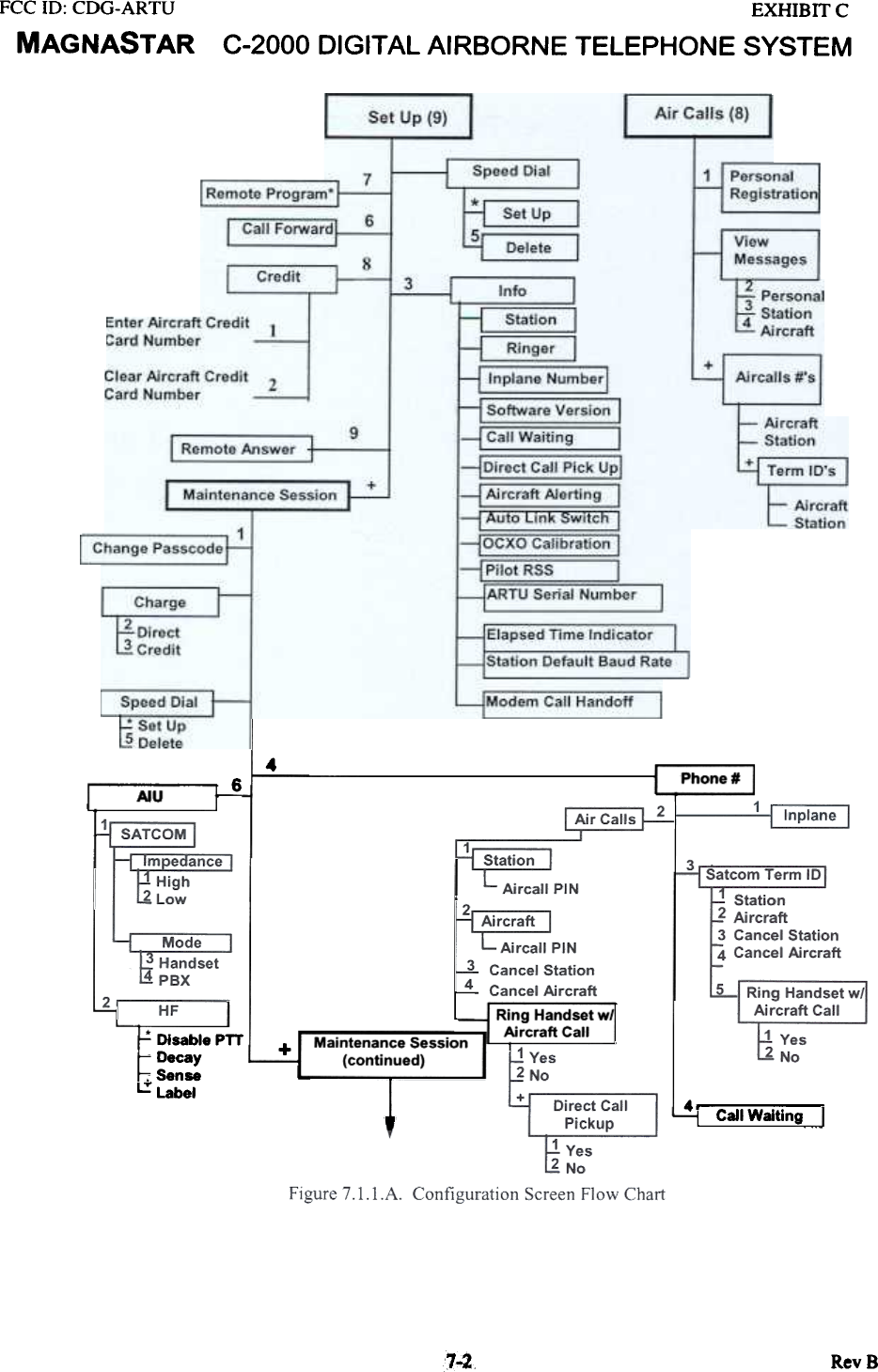
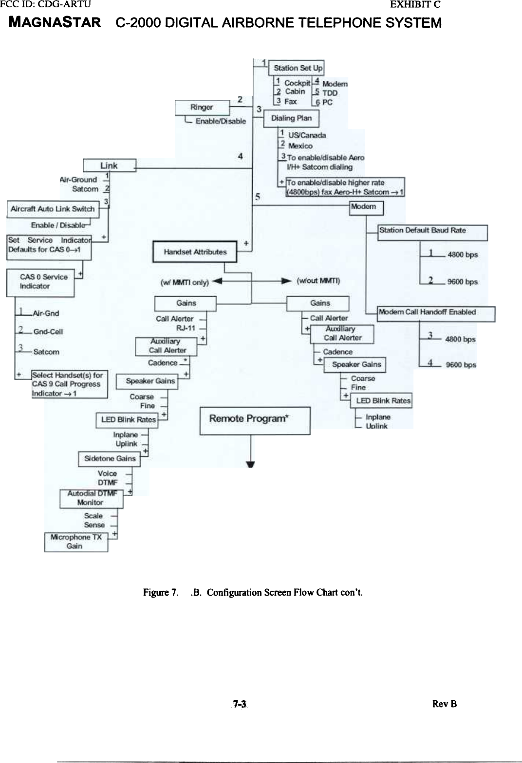
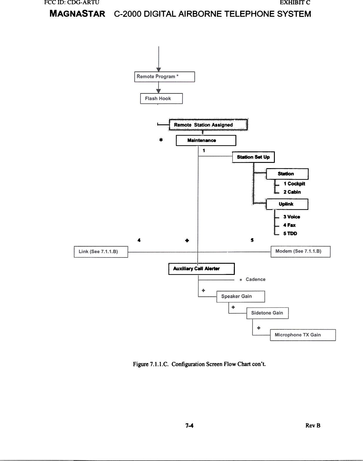
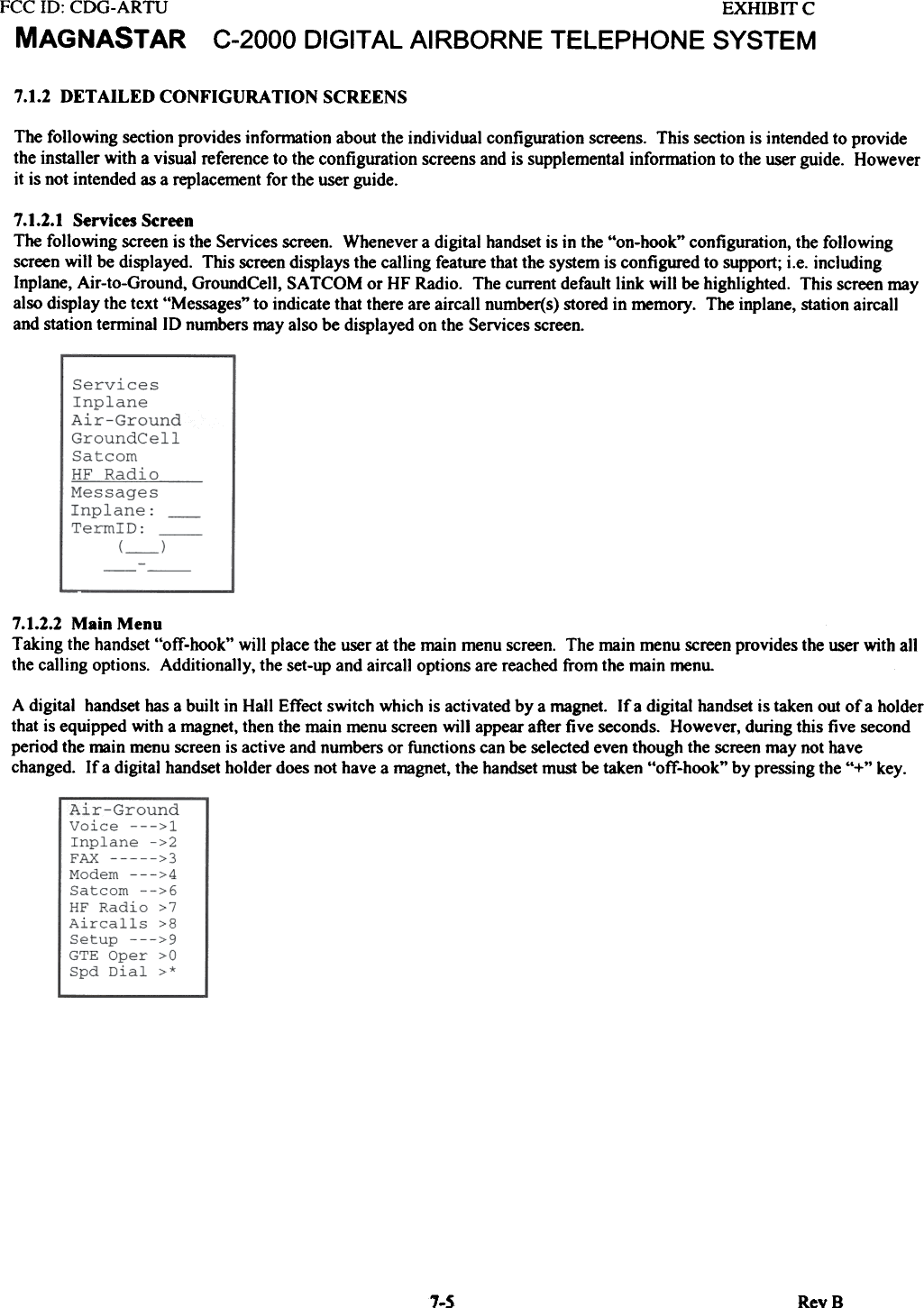
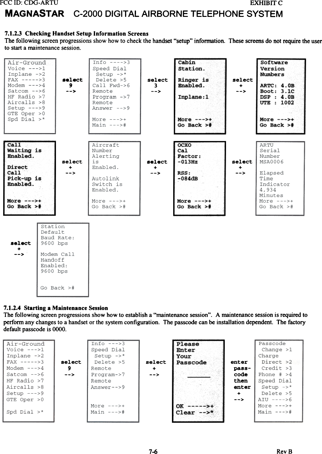
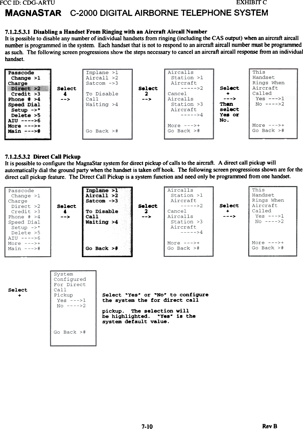
![FCC ill: CDG-ARTUMAGNASTAREXHIBITCC-2000 DIGITAL AIRBORNE TELEPHONE SYSTEM7.0 PROGRAMMING THE MAGNAST AR SYSTEM7.1 HANDSET CONFIGURATION SCREENSThis section provides detailed information in support of the C-2000 user guide to help the installer with the configurationprogramming of the MagnaStar system Included in this section are a flow chart of the maintenance set-up screens anddescriptions of the handset set-up screens. These screens apply to ARTU software version ARTCC40B.7.1.1 CONFIGURATION SCREEN FLOW CHARTA flow chart of the MagnaStar maintenance screens is shown in this section. The flow chart is intended to provide areference guide to help the installers quickly find the location of individual configuration screens. The flow chart includesboth the set-up maintenance screens and the airca]] screens.1.1 RevS](https://usermanual.wiki/Raytheon-IIS/ARTU.installation-manual-part-three/User-Guide-257061-Page-1.png)