Raytheon IIS ARTU Air-Ground Radio System User Manual installation manual part four
Raytheon Company Air-Ground Radio System installation manual part four
Contents
installation manual part four
FCC ill: CDG-ARTU
MAGNASTAR
EXHIBIT C
C-2000 DIGITAL AIRBORNE TELEPHONE SYSTEM
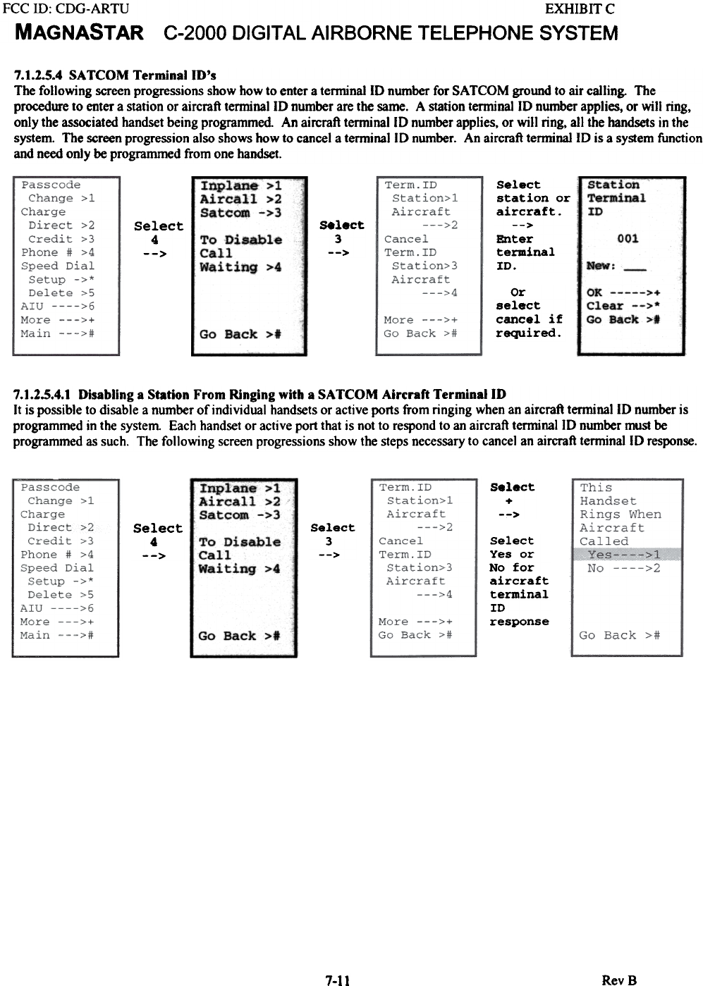
7.1.2.5.4 SATCOM Terminal ro's
The following screen progressions show how to enter a terminal 10 number for SATCOM ground to air calling. The
procedure to enter a station or aircraft terminal 10 number are the same. A station terminal 10 number applies, or will ring,
only the associated handset being programmed. An aircraft terminal 10 number applies, or will ring, all the handsets in the
system. The screen progression also shows how to cancel a terminal 10 number. An aircraft terminal 10 is a system function
and need only be programmed from one handset.
Station
Terminal
ID
Inplane > 1
Aircall >2
Satcom ->3 s.lect
3
-->
select
4
--> 001
select
station or
aircraft.
-->
Enter
terminal
ID.
To Disable
Call
Waiting >4 New:
OK >+
Clear -->*
Go Back >t
Or
select
cancel if
required.Go Back >t
7.1.2.5.4.1 Disabling a Station From Ringing with a SA TCOM Aircraft TerminailD
It is possible to disable a number of individual handsets or active ports from ringing when an aircraft terminallD number is
programmed in the system Each handset or active port that is not to respond to an aircraft terminallD number must be
programmed as such. The following screen progressions show the steps necessary to cancel an aircraft terminallD response.
Inplane > 1
Aircall >2
Satcom ->3
select
+
-->
Select
3
-->
Select
4
--> Select
Yes or
No for
aircraft
terminal
ID
response
To Disable
Call
Waiting >4
Go Back >.
RevB
7-11
EXHIBITC
C-2000 DIGITAL AIRBORNE TELEPHONE SYSTEM
FCC ill: CDG-ARTU
MAGNASTAR
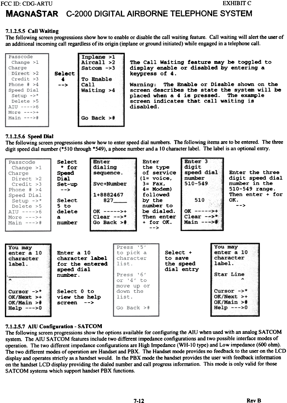
7.1.2.5.5 CaD Waiting
The following screen progressions show bow to enable or disable the call waiting feature. Call waiting will alert the user of
an additional incoming call regardless of its origin (inplane or ground initiated) while engaged in a telephone call.
Inplane>1
Aircall >2
Satcom ->3 The call Waiting feature may be toggled to
display enable or disabled by entering a
keypress of 4.
Select
4
--> Warning: The Enable or Disable shown on the
screen describe$ the $tate the system will be
placed when a 4 is pressed. The example
screen indicates that call waiting is
disabled.
To Enable
Call
Waiting >4
Go Back >#
7.1.2.5.6 Speed Dial
The following screen progressions show how to enter speed dial numbers. The following items are to be entered. The three
digit speed dial number (*510 through *549), a phone number and a 10 character label. The label is an optional entry.
--
Enter
dialing
sequence
Enter
the type
of service
(1= voice,
3= Fax,
4= Modem)
followed
by the
number to
be dialed.
Then enter
+ for OK.
-->
Sel-
*
Spe-
Dia
Set
Enter 3
digit
speed dial
number
510-549
Enter the three
digit speed dial
number in the
510-549 range.
Then enter + for
OK.
-->
Svc+Number
1+8882467
827 510
OK >+
Clear -->.
Main --->I
OK >+
Clear -->*
Go Back >t
Select
5 to
delete
a
number
You maY--
enter a 10
character
label.
You
ent'
cha
lab
Select +
to save
the speed
dial entry
Enter a 10
character label
for the entered
speed dial
number. Star Line "
CUrsor ->*
OK/Next >+
OK/Main >t
Help --->0
CUrsor ->*
OK/Next >+
OK/Main >1
Help --->0
Select 0 to
view the help
screen -->
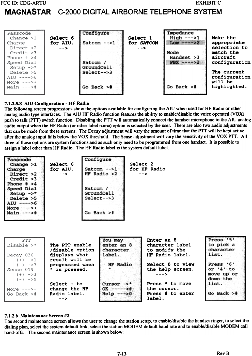
7.1.2.5.7 AIU Configuration - SATCOM
The fo)]owjng screen progressions show the options available for configuring the AlU when used wjth an analog SATCOM
system. The AlU SA TCOM features include two different impedance configurations and two possible interface modes of
operation. The two different impedance configurations are High Impedance (WH-IO type) and Low impedance (600 ohm).
The two different modes of operation are Handset and PBX. The Handset mode provides no feedback to the user on the LCD
display and operates strictly as a handset would. In the PBX mode the handset provides the user with feedback information
on the handset LCD display providing the dialed number and ca)] progress information. This mode is only valid for those
SA TCOM systems which support handset PBX functions.
RevS
7-12
ect
for
ed
1
-up
>
may
er a 10
racter
el.
FCC ID: CDG-ARTU
MAGNASTAR
EXHIB IT C
C-2000 DIGITAL AIRBORNE TELEPHONE SYSTEM
configure Impedance
~~~~~~~i
Select 1
for SAreOM
-->
Make the
appropriate
selection to
match the
aircraft
configuration
Select 6
for AIU.
--> Satcom -->1
Mode
Handset >3
~---~>2
SatcODl /
GroundCell
Select-->3
Go Back >1 Go Back >1
The current
configuration
will be
highlighted.
7.1.2.5.8 AIU Configuration - OF Radio
The following screen progressions show the options available for configuring the AIU when used for HF Radio or other
analog audio type interfaces. The AIU HF Radio function features the ability to enable/disable the voice operated (VOX)
push to talk (PTf) switch function. Disabling the PTf will automatically connect the handset microphone to the AIU analog
audio output when the HF Radio (or other label name) option is selected by the user. There are also two audio adjustments
that can be made from these screens. The Decay adjustment will vary the amount of time that the PTT will be kept active
after the analog input falls below the VOX threshold. The Sense adjustment will vary the sensitivity of the VOX PTf. All
three of these options are system functions and as such only need to be programmed from one handset. It is possible to
assign a label other than HF Radio. The HF Radio label is the system default label.
confi~
select 6
for AIU.
-->
Select 2
for HP Radio
-->
Satcom -->1
HF Radio >2
Passcode
Charige > 1
Charge
Direct >2
Credit >3
Phone I >4
Speed Dial
Setup ->*
Delete >5
AIU >6
More --->+
Main --->1
Satcom /
GroundCell
Select-->3
Go Back >1
Press '5'
to pick a
character
list.
Enter an 8
character label
to modify the
HF Radio label.
The PTT enable
/disable option
displays what
result will be
progranuned when
* is pressed.
You may
enter an 8
character
label.
HF Radio
ASelect 0 to view
the help screen.
--->
Press '6'
or '4' to
move up or-
down the
list.Select + to
change the HP
Radio label.
-->
Cursor ->.*
OK >.
Help --->0 Go Back >*
Press * to move
the cursor.
Press' to enter
label.
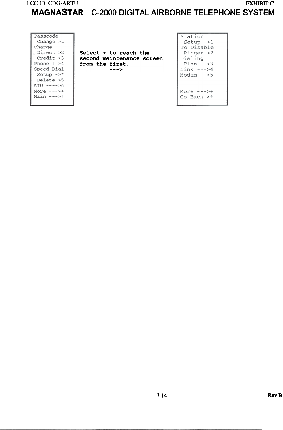
7.1.2.6 Maintenance Screen #2
The second maintenance screen allows the wer to change the station setup. to enable/disable the handset ringer. to select the
dialing plan, select the system default link, select the station MODEM default baud rate and to enable/disable MODEM call
hand-offs.. The second maintenance screen is shown below:
RevB
7~.3
FCC ill: CDG-ARTU
MAGNASTAR EXHIBIT C
C-2000 DIGITAL AI RBORNE TELEPHONE SYSTEM
Select + to reach the
second maintenance screen
from the first.
--->
7-14 RevB
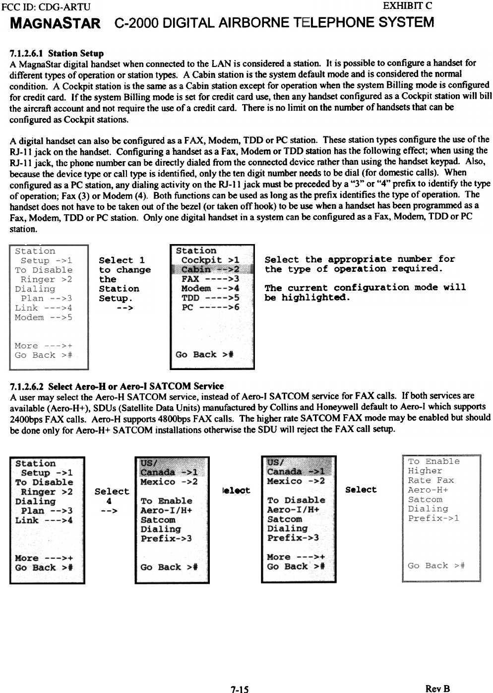
EXHIBIT C
LEPHONESYSTEM
FCC 10: CDG-ARTU
MAGNASTAR C-2000 DIGITAL AIRBORNE T
7.1.2.6.1 Station Setup
A MagnaStar digital handset when connected to the LAN is considered a station. It is possible to configure a handset for
different types of operation or station types. A Cabin station is the system default mode and is considered the normal
condition. A Cockpit station is the same as a Cabin station except for operation when the system Billing mode is configured
for credit card. If the system Billing mode is set for credit card use, then any handset configured as a Cockpit station will bill
the aircraft account and not require the use of a credit card. There is no limit on the number of handsets that can be
configured as Cockpit stations.
A digital handset can also be configured as a FAX, Modem, TDD or PC station. These station types configure the use of the
RJ-II jack on the handset. Configuring a handset as a Fax, Modem or TDD station has the following effect; when using the
RJ-II jack, the phone number can be directly dialed from the connected device mther than using the handset keypad Also,
because the device type or call type is identified, only the ten digit number needs to be dial (for domestic calls). When
configured as a PC station, any dialing activity on the RJ-II jack must be preceded by a "3" or "4" prefix to identify the type
of opemtion; Fax (3) or Modem (4). Both functions can be used as long as the prefix identifies the type of opemtion. The
handset does not have to be taken out of the bezel (or taken otThook) to be use when a handset has been programmed as a
Fax, Modem, TDD or PC station. Only one digital handset in a system can be configured as a Fax, Modem, TDD or PC
station.
Select the appropriate number for
the type of operation required.
Stati
Cock
Q.x
FAX
Mode
TDD
PC-
The current configuration mode will
be highlighted.
Select 1
to change
the
Station
Setup.
-->
Go Back >*
7.1.2.6.2 Select Aero-H or Aero-I SATCOM Service
A user may select the Aero-H SA TCOM service, instead of Aero-l SA TCOM service for FAX calls. If both services are
available (Aero-H+), SDUs (Satellite Data Units) manufactured by Collins and Honeywell default to Aero-l which supports
2400bps FAX calls. Aero-H supports 4800bps FAX calls. The higher rate SA TCOM FAX mode may be enabled but should
be done only for Aero-H+ SA TCOM installations otherwise the SDU will reject the FAX call setup.
us/
Cana~
Mexico
.~
Mexico ~I
>2
Station -
Setup ->1
To Disable
Ringer >2
Dialing
Plan -->3
Link --->4
Select
!elect
Select
4
--> To
Ae:(
Sa
Di~
Pr"
To
Ael
Sat
Dir:
Prf'
More --->+
Go Back >1
More --->+
Go Back >t Go Back >t
RevB
7-15
on
~!,~~l
~[c+"'"'>2
>3
III -->4
>5
>6
Disable
:-o-I/H+
~com
tling
}fix->3
an
:0-
:ca
lli
Ifi
able
I/H+
m
ng
x->3
FCC ill: CDG-ARTU
MAGNASTAR
EXHIB rr c
C-2000 DIGITAL AIRBORNE TELEPHONE SYSTEM
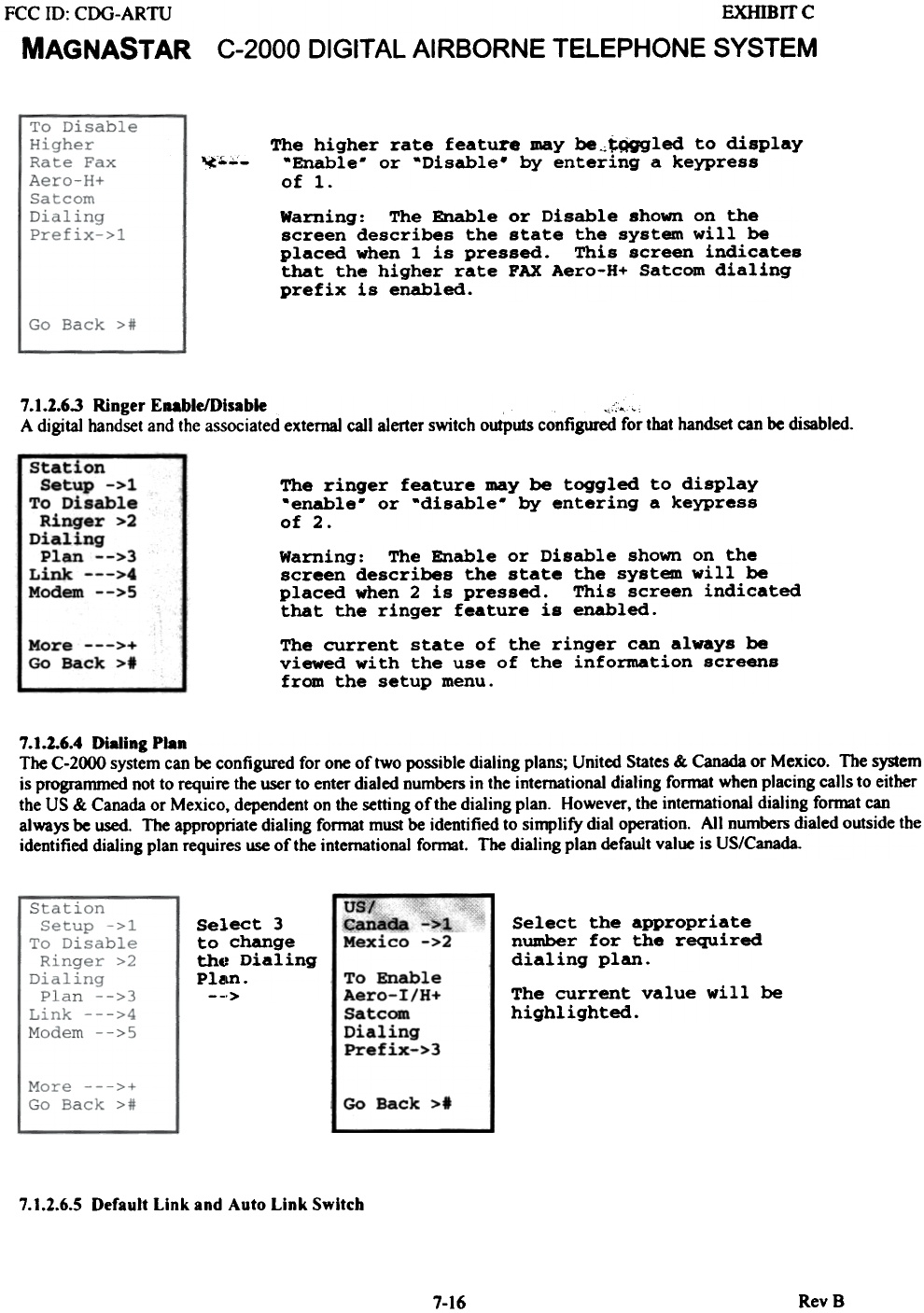
The higher rate feature may be~tQgg1ed to display
-Enable- or -Disable. by entering a keypress
of 1.
~..;;;-
Warning: The Enable or Disable shown on the
screen describes the state the system will be
placed when 1 is pressed. This screen indicates
that the higher rate PAX Aero-H+ Satcom dialing
prefix is enabled.
7.1.1.6.3 Ringer Enable/Disable ~::,,'
A digital handset and the associated external call alerter switch outputs configured for that handset can be disabled.
The ringer feature may be toggled to display
-enable- or -disable- by entering a keypress
of 2.
Warning: The Enable or Disable shown on the
screen describes the state the system will be
placed when 2 is pressed. This screen indicated
that the ringer feature is enabled.
The current state of the ringer can always be
viewed with the use of the information screens
from the setup menu.
7.1.2.6.4 Dialing Plan
The C-2000 system can be configured for one of two possible dialing plans; United States & Canada or Mexico. The system
is programmed not to require the user to enter dialed numbers in the international dialing format when placing calls to either
the US & Canada or Mexico, dependent on the setting of the dialing plan. However, the international dialing format can
always be used. The appropriate dialing format must be identified to simplify dial operation. All numbers dialed outside the
identified dialing plan requires use of the international format. The dialing plan default value is US/Canada.
uSj-
~na~
Mexico >1
.>2
Se1
to
thE
Pl!
Select the appropriate
nwnber for the required
dialing plan.
To Enable
Aero-I/H+
Satcom
Dialing
Prefix-»
The current value will be
highlighted.
Go Back >t
7.1.2.6.5 Default Link and Auto Link Switch
7-16 RevB
.ect 3
change
t Dialing
~n.
.>
EXHIBrrc
C-2000 DIGITAL AIRBORNE TELEPHONE SYSTEM
FCC ill: CDG-ARTU
MAGNASTAR
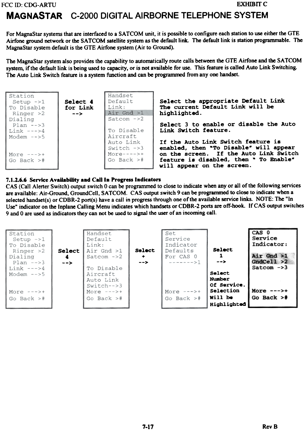
For MagnaStar systems that are interfaced to a SA TCOM unit, it is possible to configure each station to use either the GTE
Airfone ground network or the SA TCOM satellite system as the default link. The default link is station programmable. The
MagnaStar system default is the GTE Airfone system (Air to Ground).
The MagnaStar system also provides the capability to automatically route calls between the GTE Airfone and the SA TCOM
system, if the default link is being used to capacity, or is not available for use. This feature is called Auto Link Switching.
The Auto Link Switch feature is a system function and can be programmed from anyone handset.
Select the appropriate Default Link
The current Default Link will be
highlighted.
Select 4
for Link
-->
Select 3 to enable or disable the Auto
Link SWitch feature.
If the Auto Link SWitch feature is
enabled, then -To Disable- will appear
on the screen. If the Auto Link SWitch
feature is disabled, then - To Enable-
will appear on the screen.
7.1.2.6.6 Service Availability and Call In Progress Indieaton
CAS (Call Alerter Switch) output switch 0 can be programmed to close to indicate when any or all of the following services
are available: Air-Ground, GroundCell, SA TCOM. CAS oUtput switch 9 can be Progranuned to close to indicate when a
selected handset(s) or CDBR-2 port(s) have a call in progress through one of the available service links. NOTE: The t'In
Use" indicator on the Inplane Calling Menu indicates which handsets or CDBR-2 ports are off-hook. If CAS output switches
9 and 0 are used as indicators they can IK>t be used to signal the user of an incoming call.
---
CASO
service
Indicator:
Select
+
-->
Select
1
-->
Select
4
--> Air and >1
GndCell >2
Satcom ->3
More --->+
Go Qack >t
Select
Number
Of Service.
Selection
Will be
Highlighted
7-17 Rev 8
FCC ID: COG-ARTU
MAGNASTAR
EXHlBITC
C-2000 DIGITAL AIRBORNE TELEPHONE SYSTEM
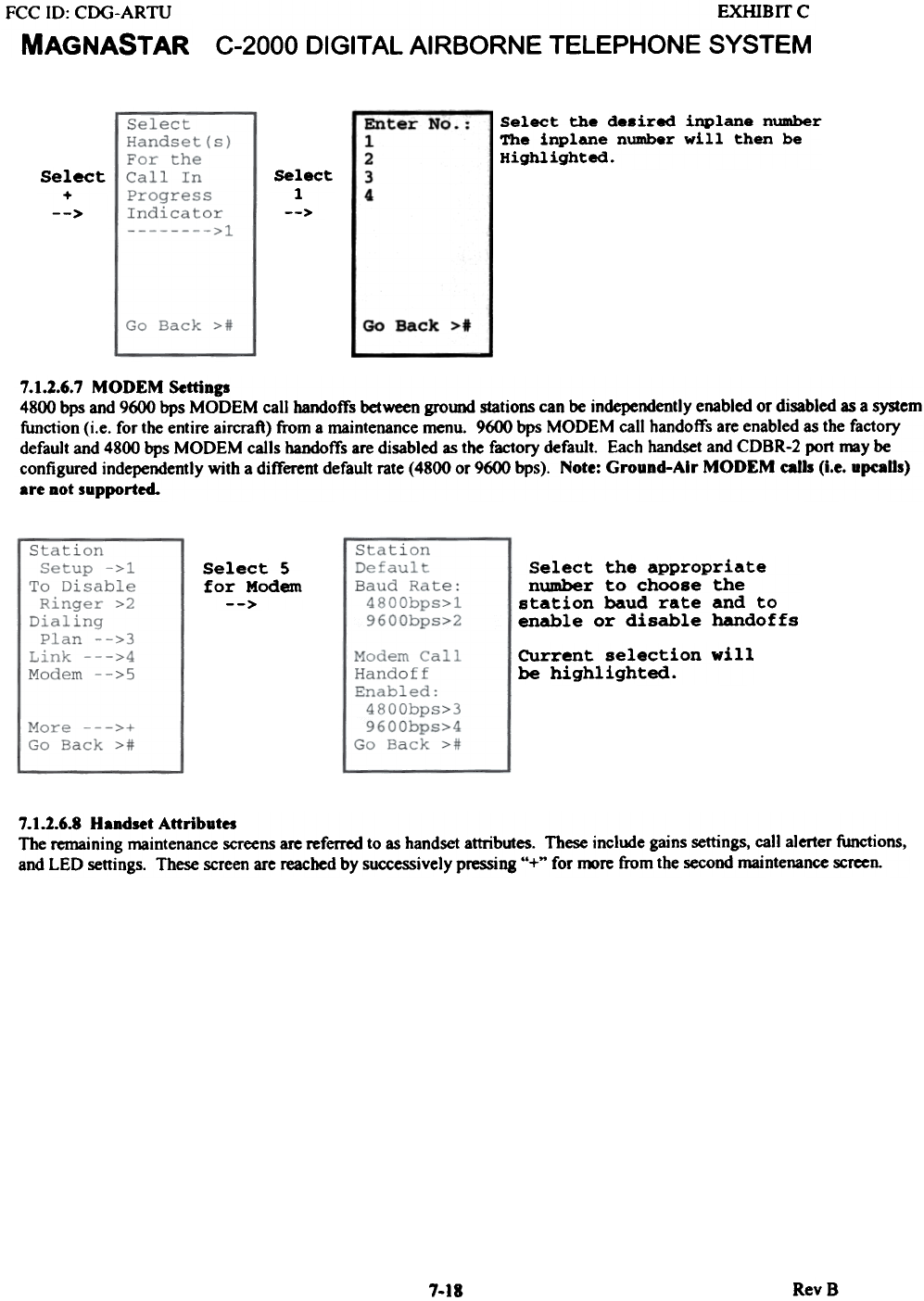
Select the de. ired inplane number
The inplane number will then be
Highlighted.
~--
Enter No
1
2
3
4
select
I
-->
Select
+
-->
Go Back >1
7.1.2..6.7 MODEM Settings
4800 bps and 9600 bps MODEM call bandoffs between ground stations can be independently enabled or disabled as a system
function (i.e. for the entire aircraft) from a maintenance menu. 9600 bps MODEM call handoffs are enabled as the factory
default and 4800 bps MODEM calls handoffs are disabled as the factory default. Each handset and CDBR-2 port may be
configured independently wjth a different default rate (4800 or 9600 bps). Note: Ground-Air MODEM eatls (i.e. upealls)
are Dot supported.
Select 5
for Modem
-->
Select the appropriate
number to choose the
station baud rate and to
enable or disable handoffs
CUrrent selection will
be highlighted.
7.1.2.6.8 Handset Attributes
The remaining maintenance screens are referred to as handset attributes. These include gains settings, call alerter functions,
and LED settings. These screen are reached by successively pressing "+" for roore from the second maintenance screen.
RevS
7.18