Rockwell Collins 6229210 TRANSPONDER User Manual P1
Rockwell Collins Inc TRANSPONDER P1
Contents
User Manual P1

component
maintenance
manual
TDR-94/94D (-004 Status
and Higher) ATC/Mode S
Transponder (ICA)
34-50-96
(with illustrated parts list)
Export Control Classification Notice (ECCN) for this document is 6E991.
© Copyright 2010 Rockwell Collins, Inc. All rights reserved.

May 20, 2010
TO: HOLDERS OF THE ROCKWELL COLLINS® TDR-94/94D (-004 STATUS AND HIGHER) ATC/MODE
S TRANSPONDER (ICA) COMPONENT MAINTENANCE MANUAL WITH IPL (CPN 523-0778502)
DESCRIPTION OF REVISION NO 13, MAY 20, 2010
This page shows all pages of the manual that are added, changed, or removed. Replace the specified pages of
the manual with the new pages supplied. Record the applicable data on the Record of Revisions page.
All changed pages keep data necessary to do maintenance on all equipment models. Black bars on the side
of the page identify changes.
PAGE
NUMBER
DESCRIPTION OF REVISION AND
REASON FOR CHANGE
SERVICE
BULLETIN
EFFECTIVITY
LEP-1 thru
LEP-14
Updated to reflect current revision. None All models
LOI-3 thru
LOI-5/LOI-6
Updated to reflect current revision. None All models
LOT-1, LOT-2 Updated to reflect current revision. None All models
INTRO-3 Revised Note explaining the use of XXX. None All models
2 Revised Equipment Covered Table 1 to add
new CPNs.
None 622-9352-310,
622-9352-410,
622-9210-310,
622-9210-410
23 thru 26, 28 Revised Assembly Identification Tables, Table 6
to include new CPNs.
622-9352-310,
622-9352-410,
622-9210-310,
622-9210-410
2007, 2009/
2010
Revised Assembly Revision Level and Diagram
Reference Table 2002 to add new cards.
All models
2008 Relocation of data. None All models
2048.1/2048.2 Added Power Amplifier Circuit Card A2
(CPN 687-0722-006), Maintenance Aid and
Schematic Changes Table 2006.1.
None All models
1

PAGE
NUMBER
DESCRIPTION OF REVISION AND
REASON FOR CHANGE
SERVICE
BULLETIN
EFFECTIVITY
2048.3/2048.4
thru 2048.7/
2048.8
Added Power Amplifier Circuit Card A2 (CPN
687-0722-006), Maintenance Aid Diagram
Figure 2008.1.
None All models
2048.9/2048.10
thru 2048.13/
2048.14
Added Power Amplifier Circuit Card A2 (CPN
687-0722-006), Schematic Diagram Figure
2008.2.
None All models
2146.1/2146.2 Added CPU-I/O Programmed Assembly A5
(CPN 653-3674-025, -026) and CPU-I/O Circuit
Card A5A1 (CPN 828-2700-004), Maintenance
Aid and Schematic Changes Table 2012.1.
None All models
2146.3/2146.4
thru 2146.9/
2146.10
Added CPU-I/O Programmed Assembly A5
(CPN 653-3674-025, -026) and CPU-I/O Circuit
Card A5A1 (CPN 828-2700-004), Maintenance
Aid Diagram Figure 2021.1.
None All models
2146.11/
2146.12 thru
2146.27/
2146.28
Added CPU-I/O Programmed Assembly A5
(CPN 653-3674-025, -026) and CPU-I/O Circuit
Card A5A1 (CPN 828-2700-004), Schematic
Diagram Figure 2021.2 .
None All models
2195/2196 Revised Video Processor Circuit Card A6 (CPN
687-0726-006) and Video Processor Circuit
Card Assembly A6 (CPN 983-8019-001),
Maintenance Aid and Schematic Changes
Table 2015.
None All models
2220.1/2220.2 Added Video Processor Circuit Card A6
(CPN 687-0726-007), Maintenance Aid and
Schematic Changes Table 2015.1.
None All models
2220.3/2220.4
thru 2220.9/
2220.10
Added Video Processor Circuit Card A6 (CPN
687-0726-007), Maintenance Aid Diagram
Figure 2028.1.
None All models
2220.11/
2220.12 thru
2220.25/
2220.26
Added Video Processor Circuit Card A6 (CPN
687-0726-007), Schematic Diagram Figure
2028.2.
None All models
2

PAGE
NUMBER
DESCRIPTION OF REVISION AND
REASON FOR CHANGE
SERVICE
BULLETIN
EFFECTIVITY
2239/2240 Revised IF Receiver, DPSK Detector, and
LVPS Circuit Card A7 (CPN 687-0727-005),
Maintenance Aid and Schematic Changes
Table 2017.
None All models
2259/2260,
2261/2262
Revised IF Receiver, DPSK Detector, and
LVPS Circuit Card A7 (CPN 687-0727-005),
Schematic Diagram (Sheets 6 and 7).
None All models
9005 Revised Special Test Equipment Required.
(Preferred List) Table 9002.
None All models
10004 thru
10005/10006
Updated Equipment Designator Prefixes
table to reflect current revision and addition
of top levels CPN 622-9210-310, -410, CPN
622-9352-310, -410; addition of Chassis
Assembly, Main CPN 653-2254-039, -040,
-041, -042 and addition of new figures 20 thru
24 CPN 687-0726-007, CPN 828-2700-004,
CPN 687-0722-006, CPN 653-0030-002 and
CPN 653-0030-003.
None All models
10007 thru
10011/10012
Updated Manufacturer's Code, Name and
Address Index to reflect current revision.
None All models
10008.1/
10008.2
New pages added to Manufacturer's Code,
Name and Address Index due to new/revised
data added on previous pages (data pushed
from previous page).
None All models
10014 thru
10016, 10023
thru 10040,
10050
Updated Equipment Designator Index to reflect
current revision.
None All models
3

PAGE
NUMBER
DESCRIPTION OF REVISION AND
REASON FOR CHANGE
SERVICE
BULLETIN
EFFECTIVITY
10014.1/
10014.2,
10024.1/
10024.2,
10026.1/
10026.2,
10028.1/
10028.2,
10032.1/
10032.2,
10034.1/
10034.2,
10036.1/
10036.2,
10038.2/
10038.2
New pages added to Equipment Designator
Index due to new/revised data added on
previous pages (data pushed from previous
page). These pages also updated to reflect
current revision.
None All models
10016.1/
10016.2,
10040.1/
10040.2
New pages added to Equipment Designator
Index due to new/revised data added on
previous pages (data pushed from previous
page).
None All models
10051 thru
10083/10084
Updated Numerical Index to reflect current
revision.
None All models
4

PAGE
NUMBER
DESCRIPTION OF REVISION AND
REASON FOR CHANGE
SERVICE
BULLETIN
EFFECTIVITY
10052.1/
10052.2,
10054.1/
10054.2,
10056.1/
10056.2,
10058.1/
10058.2,
10060.1/
10060.2,
10062.1/
10062.2,
10064.1/
10064.2,
10068.1/
10068.2,
10074.1/
10074.2,
10076.1/
10076.2,
10078.1/
10078.2,
10080.1/
10080.2,
10082.1/
10082.2
New pages added to Numerical Index due to
new/revised data added on previous pages
(data pushed from previous page). These
pages also updated to reflect current revision.
None All models
10085 thru
10090, 10091
thru 10101/
10102
Updated Optional Vendor Index to reflect
current revision.
None All models
10103/10104 Updated Figure 1 illustration and illustration
title to reflect current revision and addition
of top levels CPN 622-9210-310, -410, CPN
622-9352-310, -410.
None All models
10105 thru
10107/10108
Updated Figure 1 to reflect current revision,
addition of top levels (items 1Y thru 2A) and
correction of item 1X nomenclature.
None All models
5

PAGE
NUMBER
DESCRIPTION OF REVISION AND
REASON FOR CHANGE
SERVICE
BULLETIN
EFFECTIVITY
10111/10112,
10113 thru
10114.1/
10114.2
Updated Figure 2 to reflect current revision for
top level CPN 653-2255-006.
None All models
10121/10122 Updated Figure 4 illustration and illustration title
to reflect current revision and addition of top
levels CPN 653-2254-039, -040, -041, -042.
None All models
10123 thru
10127/10128
Updated Figure 4 to reflect current revision and
addition of top level items 1U thru 1X.
None All models
10124.1/
10124.2,
10126.3/
10126.4
New pages added to Figure 4 due to
new/revised data added on previous pages
(data pushed from previous page). These
pages updated to reflect current revision.
None All models
10157, 10158 Updated Figure 7 to reflect current next higher
assembly reference for item 1.
None All models
10158.1/
10158.2
New pages added to Figure 7 due to
new/revised data added on previous pages
(data pushed from previous page).
None All models
10349 thru
10366
Added new Figure 20, CPN 687-0726-007. None All models
10367 thru
10382
Added new Figure 21, CPN 828-2700-004. None All models
10383 thru
10396
Added new Figure 22, CPN 687-0722-006. None All models
10397/10398 Added new Figure 23, CPN 653-0030-002 (no
illustration required).
None All models
10399/10400 Added new Figure 24, CPN 653-0030-003 (no
illustration required).
None All models
6

TDR-94/94D (-004 Status
and Higher) ATC/Mode S
Transponder (ICA)
component maintenance manual
(with illustrated parts list)
This manual includes data for the equipment that follows:
Unit Model Collins Part No
ATC/Mode S Transponder TDR-94 622-9352-004, -005, -006, -007, -008, -108,
-207, -308, -309, -310, -408, -409, -410
ATC/Mode S Transponder TDR-94D 622-9210-004, -005, -006, -007, -008, -108,
-207, -308, -309, -310, -408, -409, -410
Rockwell Collins, Inc.
Printed in the United States of America Cedar Rapids, Iowa 52498
© Copyright 2010 Rockwell Collins, Inc. All rights reserved. CAGE Code: 4V792
523-0778502-Dg1113
1st Edition, Jul 01/1998
13th Revision, May 20/2010
7'5B&00B0$<B
34-50-96 T-1

ROCKWELL COLLINS
COMPONENT MAINTENANCE MANUAL with IPL
TDR-94, PART NO 622-9352
Export Control Classification Notice (ECCN) for this document is 6E991.
PROPRIETARY NOTICE
FREEDOM OF INFORMATION ACT (5 USC 552) AND DISCLOSURE OF CONFIDENTIAL
INFORMATION GENERALLY (18 USC 1905)
This document and the information disclosed herein are proprietary data of Rockwell Collins,
Inc. Neither this document nor the information contained herein shall be used, reproduced,
or disclosed to others without the written authorization of Rockwell Collins, Inc., except to the
extent required for installation or maintenance of recipient’s equipment. This document is
being furnished in confidence by Rockwell Collins, Inc. The information disclosed herein falls
within exemption (b) (4) of 5 USC 552 and the prohibitions of 18 USC 1905.
SOFTWARE COPYRIGHT NOTICE
© COPYRIGHT 2000-2010 ROCKWELL COLLINS, INC. ALL RIGHTS RESERVED.
All software resident in this equipment is protected by copyright.
We try to supply manuals that are free of errors, but some can occur. If a problem is
found with this manual, you can send the necessary data to Rockwell Collins. When
you report a specified problem, give short instructions. Include the manual part number,
the paragraph or figure number, and the page number.
To send data to Rockwell Collins about this manual:
Address: Rockwell Collins, Inc.
350 Collins Road NE, M/S 153-250
Cedar Rapids, IA 52498-0001
Email: techmanuals@rockwellcollins.com
To get more manuals:
Address: Rockwell Collins, Inc.
Customer Response Center
400 Collins Road NE, M/S 133-100
Cedar Rapids, IA 52498-0001
TELEPHONE: 1.888.265.5467
INTERNATIONAL: 1.319.265.5467
FAX NO: 319.295.4941
Email: response@rockwellcollins.com
34-50-96 T-2
May 20/10

ROCKWELL COLLINS
COMPONENT MAINTENANCE MANUAL with IPL
TDR-94, PART NO 622-9352
RECORD OF REVISIONS
REV
NO
ISSUE
DATE
DATE
INSERTED
BY REV
NO
ISSUE
DATE
DATE
INSERTED
BY
1 Ed Jul 1/98
1 Rev May 18/06
2 Rev Nov 02/06
3 Rev Nov 10/06
4 Rev Apr 17/07
5 Rev May 07/07
6 Rev Jul 31/07
7 Rev Mar 14/08
8 Rev Jun 20/08
9 Sep 25/08
10 Oct 13/08
11 Nov 7/08
12 Dec 16/09
13 May 20/10
34-50-96 RR-1/RR-2
May 20/10

ROCKWELL COLLINS
COMPONENT MAINTENANCE MANUAL with IPL
TDR-94, PART NO 622-9352
RECORD OF TEMPORARY REVISIONS
TEMPORARY
REV NO
PA G E
NUMBER
ISSUE
DATE
BY DATE
REMOVED
BY
1 Title Page Feb 25/99 Rockwell Collins Nov 1/00 Rockwell Collins
1 1 Feb 25/99 Rockwell Collins Nov 1/00 Rockwell Collins
2 198.44 Oct 28/99 Rockwell Collins Nov 8/02 Rockwell Collins
2 198.52 Oct 28/99 Rockwell Collins May 18/06 Rockwell Collins
3 198.35 Nov 30/99 Rockwell Collins Dec 22/99 Rockwell Collins
3 602 Nov 30/99 Rockwell Collins May 18/06 Rockwell Collins
4 198.35 Dec 22/99 Rockwell Collins Apr 17/01 Rockwell Collins
5 198.103 Jan 4/00 Rockwell Collins May 18/06 Rockwell Collins
5 198.114 Jan 4/00 Rockwell Collins May 18/06 Rockwell Collins
6 198.1 Jan 31/00 Rockwell Collins Apr 6/00 Rockwell Collins
7 198.11 Feb 28/00 Rockwell Collins May 18/06 Rockwell Collins
8 107 Mar 1/00 Rockwell Collins Jun 27/00 Rockwell Collins
9 198.1 Apr 6/00 Rockwell Collins Aug 29/02 Rockwell Collins
10 198.25 Apr 24/00 Rockwell Collins May 18/06 Rockwell Collins
11 107 Jun 27/00 Rockwell Collins Dec 22/00 Rockwell Collins
11 902 Jun 27/00 Rockwell Collins Dec 22/00 Rockwell Collins
12 101 Sep 27/00 Rockwell Collins Nov 8/02 Rockwell Collins
13 Title Page Nov 1/00 Rockwell Collins Dec 19/00 Rockwell Collins
13 1 Nov 1/00 Rockwell Collins Dec 19/00 Rockwell Collins
14 Title Page Dec 19/00 Rockwell Collins Jan 17/01 Rockwell Collins
14 1 Dec 19/00 Rockwell Collins Nov 8/02 Rockwell Collins
14 198.32 Dec 19/00 Rockwell Collins Aug 20/04 Rockwell Collins
14 1011 Dec 19/00 Rockwell Collins Jan 17/01 Rockwell Collins
14 1015 Dec 19/00 Rockwell Collins Mar 16/01 Rockwell Collins
15 107 Dec 22/00 Rockwell Collins Nov 26/01 Rockwell Collins
15 902 Dec 22/00 Rockwell Collins Nov 26/01 Rockwell Collins
16 Title Page Jan 17/01 Rockwell Collins Nov 8/02 Rockwell Collins
34-50-96 RTR-1
May 18/06

ROCKWELL COLLINS
COMPONENT MAINTENANCE MANUAL with IPL
TDR-94, PART NO 622-9352
RECORD OF TEMPORARY REVISIONS
TEMPORARY
REV NO
PA G E
NUMBER
ISSUE
DATE
BY DATE
REMOVED
BY
16 1011 Jan 17/01 Rockwell Collins Mar 16/01 Rockwell Collins
17 198.60 Feb 26/01 Rockwell Collins May 18/06 Rockwell Collins
17 198.73 Feb 26/01 Rockwell Collins May 18/06 Rockwell Collins
18 198.6 Mar 16/01 Rockwell Collins May 18/06 Rockwell Collins
18 198.17 Mar 16/01 Rockwell Collins May 18/06 Rockwell Collins
18 198.27 Mar 16/01 Rockwell Collins May 18/06 Rockwell Collins
18 TR-14, pg 5 Mar 16/01 Rockwell Collins Aug 20/04 Rockwell Collins
18 198.33 Mar 16/01 Rockwell Collins Aug 20/04 Rockwell Collins
18 1011 Mar 16/01 Rockwell Collins Oct 3/02 Rockwell Collins
18 1013 Mar 16/01 Rockwell Collins May 18/06 Rockwell Collins
18 1015 Mar 16/01 Rockwell Collins Jun 28/05 Rockwell Collins
19 198.35 Apr 17/01 Rockwell Collins May 17/01 Rockwell Collins
20 137 May 8/01 Rockwell Collins May 18/06 Rockwell Collins
20 198.91 May 8/01 Rockwell Collins May 18/06 Rockwell Collins
20 198.95 May 8/01 Rockwell Collins May 18/06 Rockwell Collins
20 198.102 May 8/01 Rockwell Collins May 18/06 Rockwell Collins
20 198.107 May 8/01 Rockwell Collins May 18/06 Rockwell Collins
20 198.113 May 8/01 Rockwell Collins May 18/06 Rockwell Collins
20 198.117 May 8/01 Rockwell Collins May 18/06 Rockwell Collins
21 108 May 17/01 Rockwell Collins May 18/06 Rockwell Collins
21 136 May 17/01 Rockwell Collins May 18/06 Rockwell Collins
21 198.16 May 17/01 Rockwell Collins May 18/06 Rockwell Collins
21 198.34 May 17/01 Rockwell Collins May 18/06 Rockwell Collins
21 198.35 May 17/01 Rockwell Collins May 18/06 Rockwell Collins
21 198.37 May 17/01 Rockwell Collins May 18/06 Rockwell Collins
21 198.88 May 17/01 Rockwell Collins May 18/06 Rockwell Collins
22 107 Nov 26/01 Rockwell Collins May 18/06 Rockwell Collins
34-50-96 RTR-2
May 18/06

ROCKWELL COLLINS
COMPONENT MAINTENANCE MANUAL with IPL
TDR-94, PART NO 622-9352
RECORD OF TEMPORARY REVISIONS
TEMPORARY
REV NO
PA G E
NUMBER
ISSUE
DATE
BY DATE
REMOVED
BY
22 902 Nov 26/01 Rockwell Collins May 14/03 Rockwell Collins
23 106 Dec 10/01 Rockwell Collins May 18/06 Rockwell Collins
23 107 Dec 10/01 Rockwell Collins May 18/06 Rockwell Collins
23 901 Dec 10/01 Rockwell Collins Aug 20/04 Rockwell Collins
23 902 Dec 10/01 Rockwell Collins Nov 22/02 Rockwell Collins
24 198.1 Aug 29/02 Rockwell Collins Nov 13/02 Rockwell Collins
25 198.64 Sep 26/02 Rockwell Collins May 18/06 Rockwell Collins
25 198.65 Sep 26/02 Rockwell Collins May 18/06 Rockwell Collins
25 198.66 Sep 26/02 Rockwell Collins May 18/06 Rockwell Collins
25 198.67 Sep 26/02 Rockwell Collins May 18/06 Rockwell Collins
25 198.78 Sep 26/02 Rockwell Collins May 18/06 Rockwell Collins
25 198.79 Sep 26/02 Rockwell Collins May 18/06 Rockwell Collins
25 198.80 Sep 26/02 Rockwell Collins May 18/06 Rockwell Collins
25 198.81 Sep 26/02 Rockwell Collins May 18/06 Rockwell Collins
26 1011 Oct 3/02 Rockwell Collins Jun 28/05 Rockwell Collins
27 Title Page Nov 8/02 Rockwell Collins Jan 19/05 Rockwell Collins
27 1 Nov 8/02 Rockwell Collins Jan 19/05 Rockwell Collins
27 101 Nov 8/02 Rockwell Collins May 18/06 Rockwell Collins
27 198.44 Nov 8/02 Rockwell Collins May 18/06 Rockwell Collins
28 140 Nov 13/02 Rockwell Collins Jun 25/04 Rockwell Collins
29 902 Nov 22/02 Rockwell Collins Aug 20/04 Rockwell Collins
30 198.71 Mar 7/03 Rockwell Collins May 18/06 Rockwell Collins
30 198.82 Mar 7/03 Rockwell Collins May 18/06 Rockwell Collins
31 902 May 14/03 Rockwell Collins Aug 20/04 Rockwell Collins
32 129 Jun 25/04 Rockwell Collins May 18/06 Rockwell Collins
32 140 Jun 25/04 Rockwell Collins Aug 20/04 Rockwell Collins
32 198.61 Jun 25/04 Rockwell Collins May 18/06 Rockwell Collins
34-50-96 RTR-3
May 18/06

ROCKWELL COLLINS
COMPONENT MAINTENANCE MANUAL with IPL
TDR-94, PART NO 622-9352
RECORD OF TEMPORARY REVISIONS
TEMPORARY
REV NO
PA G E
NUMBER
ISSUE
DATE
BY DATE
REMOVED
BY
32 198.75 Jun 25/04 Rockwell Collins May 18/06 Rockwell Collins
33 198.32 Aug 20/04 Rockwell Collins May 18/06 Rockwell Collins
33 901 Aug 20/04 Rockwell Collins May 18/06 Rockwell Collins
33 902 Aug 20/04 Rockwell Collins Oct 20/04 Rockwell Collins
34 140 Oct 20/04 Rockwell Collins Jan 19/05 Rockwell Collins
34 902 Oct 20/04 Rockwell Collins Apr 18/05 Rockwell Collins
35 Title Page Jan 19/05 Rockwell Collins Jun 28/05 Rockwell Collins
35 1 Jan 19/05 Rockwell Collins May 18/06 Rockwell Collins
35 140 Jan 19/05 Rockwell Collins May 18/06 Rockwell Collins
35 198.41 Jan 19/05 Rockwell Collins May 18/06 Rockwell Collins
36 902 Apr 18/05 Rockwell Collins Oct 7/05 Rockwell Collins
37 Title Page Jun 28/05 Rockwell Collins May 18/06 Rockwell Collins
37 198.38 Jun 28/05 Rockwell Collins May 18/06 Rockwell Collins
37 1011 Jun 28/05 Rockwell Collins May 18/06 Rockwell Collins
37 1015 Jun 28/05 Rockwell Collins May 18/06 Rockwell Collins
37 1016 Jun 28/05 Rockwell Collins May 18/06 Rockwell Collins
38 902 Oct 7/05 Rockwell Collins Jan 3/06 Rockwell Collins
39 902 Jan 3/06 Rockwell Collins Feb 22/06 Rockwell Collins
40 902 Feb 22/06 Rockwell Collins May 18/06 Rockwell Collins
34-50-96 RTR-4
May 18/06

ROCKWELL COLLINS
COMPONENT MAINTENANCE MANUAL with IPL
TDR-94, PART NO 622-9352
SERVICE BULLETIN LIST
SERVICE
BULLETIN NO
SUBJECT MANUAL
REVISION
NUMBER
MANUAL
REVISION
DATE
NOTE: Alert Service Bulletins are produced on blue colored paper with the heading ALERT.
When an ALERT Service Bulletin is received, take immediate action.
1 thru 12 These service bulletins are marked out on
the unit identification plate of each -004
status TDR-94 and TDR-94D.
1/0 Jul 1/98
13 Converts TDR-94 (-003 status) and TDR-94D
(-003 status) to -004 status
1/0 Jul 1/98
14 Reduce uncommanded transitions to standby
in burst tune applications
1/0 Jul 1/98
15 Reduce electromagnetic emissions 1/0 Jul 1/98
16 Add Diode Isolation to Strap Inputs 1/1 May 18/06
17 Convert -004 Status to -005 Status 1/1 May 18/06
18 Convert TDR-94 to TDR-94D 1/1 May 18/06
19 TCAS Bus Operation During Standby Mode
(Convert -004/005 Status to -006 Status)
1/1 May 18/06
20 SW Update and TCAS Bus Operation During
Standby Mode (Convert -004/005 Status to
-006 Status and Update -006 SW)
1/1 May 18/06
21 Intermittent TCAS Bus Failure 1/1 May 18/06
22 Reduce Electromagnetic Emmisions 1/1 May 18/06
23 Update Nameplate for JTSO Approval 1/1 May 18/06
24 Repair Instructions to Replace Obsolete
Synthesizer Board
1/1 May 18/06
25 Facilitate A7 Replacement Board Due to
Non-Procurable Part U104
1/1 May 18/06
26 Reduce Occurrences of Extremely Cold
Temp Failures at Start Up
1/1 May 18/06
501 Incorporate Elementary/Enhanced Surveillance
(Converts -004/005 Status to -007 Status)
1/1 May 18/06
502 Incorporate Elementary/Enhanced Surveillance
(Converts -007 Status to -008 Status)
1/1 May 18/06
503 Addition of ADS-B Capability (Convert
-007/008 Status to -108)
1/1 May 18/06
34-50-96 SBL-1
May 07/07

ROCKWELL COLLINS
COMPONENT MAINTENANCE MANUAL with IPL
TDR-94, PART NO 622-9352
SERVICE
BULLETIN NO
SUBJECT MANUAL
REVISION
NUMBER
MANUAL
REVISION
DATE
NOTE: Alert Service Bulletins are produced on blue colored paper with the heading ALERT.
When an ALERT Service Bulletin is received, take immediate action.
504 Rev 3 Add GAMA Label 102G "Selected Altitude"
Compatibility (Converts -007 Status to -207
Status, -008 Status to -308 Status and
-108 Status to -408 Status)
1/5 May 07/07
34-50-96 SBL-2
May 07/07

ROCKWELL COLLINS
COMPONENT MAINTENANCE MANUAL with IPL
TDR-94, PART NO 622-9352
LIST OF EFFECTIVE PAGES
SUBJECT PAGE DATE SUBJECT PAGE DATE
TITLE * T-1 May 20/10
* T-2 May 20/10
RECORD OF
REVISIONS * RR-1 May 20/10
RR-2 Blank
RECORD OF
TEMPORARY
REVISIONS RTR-1 May 18/06
RTR-2 May 18/06
RTR-3 May 18/06
RTR-4 May 18/06
SERVICE BULLETIN
LIST SBL-1 May 07/07
SBL-2 May 07/07
LIST OF EFFECTIVE
PAGES * LEP-1 May 20/10
* LEP-2 May 20/10
* LEP-3 May 20/10
* LEP-4 May 20/10
* LEP-5 May 20/10
* LEP-6 May 20/10
* LEP-7 May 20/10
* LEP-8 May 20/10
* LEP-9 May 20/10
* LEP-10 May 20/10
* LEP-11 May 20/10
* LEP-12 May 20/10
* LEP-13 May 20/10
* LEP-14 May 20/10
TA B L E O F
CONTENTS TC-1 Jun 20/08
TC-2 May 18/06
TC-3 Apr 17/07
TC-4 May 18/06
LIST OF
ILLUSTRATIONS LOI-1 May 18/06
LOI-2 Jun 20/08
* LOI-3 May 20/10
* LOI-4 May 20/10
* LOI-5 May 20/10
LOI-6 Blank
LIST OF TABLES * LOT-1 May 20/10
* LOT-2 May 20/10
INTRODUCTION INTRO-1 May 18/06
INTRO-2 May 18/06
* INTRO-3 May 20/10
INTRO-4 May 18/06
INTRO-5 May 18/06
INTRO-6 May 18/06
INTRO-7 May 18/06
INTRO-8 May 18/06
INTRO-9 May 18/06
INTRO-
10
Blank
DESCRIPTION AND
OPERATION 1 May 18/06
* 2 May 20/10
3May07/07
4May18/06
5May18/06
6May18/06
7May18/06
8May18/06
9May18/06
10 May 18/06
11 May 18/06
12 May 18/06
13 May 18/06
14 May 18/06
15 May 18/06
16 May 18/06
17 May 18/06
18 May 18/06
19 May 18/06
20 May 18/06
F 21 May 18/06
F22 Blank
* 23 May 20/10
* 24 May 20/10
* 25 May 20/10
* 26 May 20/10
*The asterisk indicates pages with content changed or added by the current change. F = Foldout Page
34-50-96 LEP-1
May 20/10

ROCKWELL COLLINS
COMPONENT MAINTENANCE MANUAL with IPL
TDR-94, PART NO 622-9352
LIST OF EFFECTIVE PAGES
SUBJECT PAGE DATE SUBJECT PAGE DATE
27 Jun 20/08
* 28 May 20/10
28.1 Jun 20/08
28.2 Blank
29 May 18/06
30 May 18/06
31 May 18/06
32 May 18/06
33 May 18/06
34 May 18/06
35 May 18/06
36 May 18/06
37 May 18/06
38 May 18/06
39 May 18/06
40 May 18/06
41 May 18/06
42 May 18/06
43 May 18/06
44 May 18/06
45 May 18/06
46 May 18/06
47 May 18/06
48 May 18/06
49 May 18/06
50 May 18/06
51 May 18/06
52 May 18/06
53 May 18/06
54 May 18/06
55 May 18/06
56 May 18/06
57 May 18/06
58 May 18/06
59 May 18/06
60 May 18/06
61 May 18/06
62 May 18/06
63 May 18/06
64 May 18/06
65 May 18/06
66 May 18/06
67 May 18/06
68 Blank
TESTING AND
FAULT ISOLATION 1001 Jun 20/08
1002 May 18/06
1003 May 18/06
1004 Blank
F 1005 May 18/06
F 1006 Blank
F 1007 May 18/06
F 1008 Blank
1009 May 18/06
1010 May 18/06
1011 May 18/06
1012 Jun 20/08
1013 May 18/06
1014 Mar 14/08
1015 May 18/06
1016 May 18/06
1017 May 18/06
1018 May 18/06
1019 May 18/06
1020 May 18/06
1021 May 18/06
1022 May 18/06
1023 May 18/06
1024 May 18/06
1025 May 18/06
1026 Nov 10/06
1027 May 18/06
1028 Dec 16/09
1028.1 Jun 20/08
1028.2 May 07/07
1028.3 May 07/07
1028.4 Blank
1029 Nov 10/06
1030 May 18/06
1031 Dec 16/09
1032 Jun 20/08
1032.1 May 07/07
1032.2 May 07/07
1033 Nov 10/06
*The asterisk indicates pages with content changed or added by the current change. F = Foldout Page
34-50-96 LEP-2
May 20/10

ROCKWELL COLLINS
COMPONENT MAINTENANCE MANUAL with IPL
TDR-94, PART NO 622-9352
LIST OF EFFECTIVE PAGES
SUBJECT PAGE DATE SUBJECT PAGE DATE
1034 May 18/06
1035 May 18/06
1036 Dec 16/09
1036.1 Jun 20/08
1036.2 May 07/07
1036.3 May 18/06
1036.4 Blank
1037 Jun 20/08
1038 May 07/07
1038.1 May 07/07
1038.2 Blank
1039 May 18/06
1040 Jun 20/08
1041 May 18/06
1042 May 18/06
1043 May 18/06
1044 Jun 20/08
1045 May 18/06
1046 Jun 20/08
1047 May 18/06
1048 Jun 20/08
1049 Jun 20/08
1050 Jun 20/08
1051 May 18/06
1052 May 18/06
1053 May 18/06
1054 May 18/06
1055 May 18/06
1056 May 18/06
1057 May 18/06
1058 May 18/06
1059 May 18/06
1060 May 18/06
1061 May 18/06
1062 May 18/06
1063 May 18/06
1064 May 18/06
1065 May 18/06
1066 May 18/06
1067 May 18/06
1068 May 18/06
1069 May 18/06
1070 May 18/06
1071 May 18/06
1072 May 07/07
1072.1 May 07/07
1072.2 May 07/07
1072.3 May 07/07
1072.4 May 07/07
1072.5 Jun 20/08
1072.6 Jun 20/08
1072.7 May 07/07
1072.8 Blank
1073 Apr 17/07
1074 May 18/06
1075 Apr 17/07
1076 May 18/06
1077 Apr 17/07
1078 May 18/06
1079 May 18/06
1080 May 18/06
1081 May 18/06
1082 May 18/06
1083 Dec 16/09
1084 Blank
SCHEMATIC AND
WIRING DIAGRAMS 2001 May 18/06
2002 May 18/06
2003 May 18/06
2004 May 18/06
2005 May 18/06
2006 May 18/06
* 2007 May 20/10
* 2008 May 20/10
* 2009 May 20/10
2010 Blank
2011 May 18/06
2012 Blank
F 2013 May 18/06
F 2014 Blank
F 2015 May 18/06
F 2016 Blank
2017 May 18/06
2018 Blank
*The asterisk indicates pages with content changed or added by the current change. F = Foldout Page
34-50-96 LEP-3
May 20/10

ROCKWELL COLLINS
COMPONENT MAINTENANCE MANUAL with IPL
TDR-94, PART NO 622-9352
LIST OF EFFECTIVE PAGES
SUBJECT PAGE DATE SUBJECT PAGE DATE
F 2019 May 18/06
F 2020 Blank
F 2021 May 18/06
F 2022 Blank
2023 May 18/06
2024 Blank
F 2025 May 18/06
F 2026 Blank
F 2027 May 18/06
F 2028 Blank
F 2029 May 18/06
F 2030 Blank
F 2031 May 18/06
F 2032 Blank
F 2033 May 18/06
F 2034 Blank
2035 May 18/06
2036 Blank
F 2037 May 18/06
F 2038 Blank
F 2039 May 18/06
F 2040 Blank
F 2041 May 18/06
F 2042 Blank
F 2043 May 18/06
F 2044 Blank
F 2045 May 18/06
F 2046 Blank
2047 May 18/06
2048 Blank
* 2048.1 May 20/10
2048.2 Blank
* F 2048.3 May 20/10
F 2048.4 Blank
* F 2048.5 May 20/10
F 2048.6 Blank
* F 2048.7 May 20/10
F 2048.8 Blank
* F 2048.9 May 20/10
F 2048.10 Blank
* F 2048.11 May 20/10
F 2048.12 Blank
* F 2048.13 May 20/10
F 2048.14 Blank
2049 May 18/06
2050 Blank
F 2051 May 18/06
F 2052 Blank
F 2053 May 18/06
F 2054 Blank
F 2055 May 18/06
F 2056 Blank
F 2057 May 18/06
F 2058 Blank
F 2059 May 18/06
F 2060 Blank
F 2061 May 18/06
F 2062 Blank
2063 May 18/06
2064 Blank
F 2065 May 18/06
F 2066 Blank
F 2067 May 18/06
F 2068 Blank
F 2069 May 18/06
F 2070 Blank
F 2071 May 18/06
F 2072 Blank
F 2073 May 18/06
F 2074 Blank
F 2075 May 18/06
F 2076 Blank
2077 May 18/06
2078 Blank
F 2079 May 18/06
F 2080 Blank
F 2081 May 18/06
F 2082 Blank
2083 May 18/06
2084 Blank
F 2085 May 18/06
F 2086 Blank
F 2087 May 18/06
F 2088 Blank
*The asterisk indicates pages with content changed or added by the current change. F = Foldout Page
34-50-96 LEP-4
May 20/10

ROCKWELL COLLINS
COMPONENT MAINTENANCE MANUAL with IPL
TDR-94, PART NO 622-9352
LIST OF EFFECTIVE PAGES
SUBJECT PAGE DATE SUBJECT PAGE DATE
F 2089 May 18/06
F 2090 Blank
2091 May 18/06
2092 May 18/06
F 2093 May 18/06
F 2094 Blank
F 2095 May 18/06
F 2096 Blank
F 2097 May 18/06
F 2098 Blank
F 2099 May 18/06
F 2100 Blank
F 2101 May 18/06
F 2102 Blank
F 2103 May 18/06
F 2104 Blank
F 2105 May 18/06
F 2106 Blank
F 2107 May 18/06
F 2108 Blank
F 2109 May 18/06
F 2110 Blank
F 2111 May 18/06
F 2112 Blank
F 2113 May 18/06
F 2114 Blank
F 2115 May 18/06
F 2116 Blank
F 2117 May 18/06
F 2118 Blank
2119 May 18/06
2120 Blank
F 2121 May 18/06
F 2122 Blank
F 2123 May 18/06
F 2124 Blank
F 2125 May 18/06
F 2126 Blank
F 2127 May 18/06
F 2128 Blank
F 2129 May 18/06
F 2130 Blank
F 2131 May 18/06
F 2132 Blank
F 2133 May 18/06
F 2134 Blank
F 2135 May 18/06
F 2136 Blank
F 2137 May 18/06
F 2138 Blank
F 2139 May 18/06
F 2140 Blank
F 2141 May 18/06
F 2142 Blank
F 2143 May 18/06
F 2144 Blank
F 2145 May 18/06
F 2146 Blank
* 2146.1 May 20/10
2146.2 Blank
* F 2146.3 May 20/10
F 2146.4 Blank
* F 2146.5 May 20/10
F 2146.6 Blank
* F 2146.7 May 20/10
F 2146.8 Blank
* F 2146.9 May 20/10
F 2146.10 Blank
* F 2146.11 May 20/10
F 2146.12 Blank
* F 2146.13 May 20/10
F 2146.14 Blank
* F 2146.15 May 20/10
F 2146.16 Blank
* F 2146.17 May 20/10
F 2146.18 Blank
* F 2146.19 May 20/10
F 2146.20 Blank
* F 2146.21 May 20/10
F 2146.22 Blank
* F 2146.23 May 20/10
F 2146.24 Blank
* F 2146.25 May 20/10
F 2146.26 Blank
*The asterisk indicates pages with content changed or added by the current change. F = Foldout Page
34-50-96 LEP-5
May 20/10

ROCKWELL COLLINS
COMPONENT MAINTENANCE MANUAL with IPL
TDR-94, PART NO 622-9352
LIST OF EFFECTIVE PAGES
SUBJECT PAGE DATE SUBJECT PAGE DATE
* F 2146.27 May 20/10
F 2146.28 Blank
2147 May 18/06
2148 May 18/06
F 2149 May 18/06
F 2150 Blank
F 2151 May 18/06
F 2152 Blank
F 2153 May 18/06
F 2154 Blank
F 2155 May 18/06
F 2156 Blank
F 2157 May 18/06
F 2158 Blank
F 2159 May 18/06
F 2160 Blank
F 2161 May 18/06
F 2162 Blank
F 2163 May 18/06
F 2164 Blank
F 2165 May 18/06
F 2166 Blank
F 2167 May 18/06
F 2168 Blank
F 2169 May 18/06
F 2170 Blank
2171 May 18/06
2172 Blank
F 2173 May 18/06
F 2174 Blank
F 2175 May 18/06
F 2176 Blank
F 2177 May 18/06
F 2178 Blank
F 2179 May 18/06
F 2180 Blank
F 2181 May 18/06
F 2182 Blank
F 2183 May 18/06
F 2184 Blank
F 2185 May 18/06
F 2186 Blank
F 2187 May 18/06
F 2188 Blank
F 2189 May 18/06
F 2190 Blank
F 2191 May 18/06
F 2192 Blank
F 2193 May 18/06
F 2194 Blank
* 2195 May 20/10
2196 Blank
F 2197 May 18/06
F 2198 Blank
F 2199 May 18/06
F 2200 Blank
F 2201 May 18/06
F 2202 Blank
F 2203 May 18/06
F 2204 Blank
F 2205 May 18/06
F 2206 Blank
F 2207 May 18/06
F 2208 Blank
F 2209 May 18/06
F 2210 Blank
F 2211 May 18/06
F 2212 Blank
F 2213 May 18/06
F 2214 Blank
F 2215 May 18/06
F 2216 Blank
F 2217 May 18/06
F 2218 Blank
F 2219 May 18/06
F 2220 Blank
* 2220.1 May 20/10
2220.2 Blank
* F 2220.3 May 20/10
F 2220.4 Blank
* F 2220.5 May 20/10
F 2220.6 Blank
* F 2220.7 May 20/10
F 2220.8 Blank
*The asterisk indicates pages with content changed or added by the current change. F = Foldout Page
34-50-96 LEP-6
May 20/10

ROCKWELL COLLINS
COMPONENT MAINTENANCE MANUAL with IPL
TDR-94, PART NO 622-9352
LIST OF EFFECTIVE PAGES
SUBJECT PAGE DATE SUBJECT PAGE DATE
* F 2220.9 May 20/10
F 2220.10 Blank
* F 2220.11 May 20/10
F 2220.12 Blank
* F 2220.13 May 20/10
F 2220.14 Blank
* F 2220.15 May 20/10
F 2220.16 Blank
* F 2220.17 May 20/10
F 2220.18 Blank
* F 2220.19 May 20/10
F 2220.20 Blank
* F 2220.21 May 20/10
F 2220.22 Blank
* F 2220.23 May 20/10
F 2220.24 Blank
* F 2220.25 May 20/10
F 2220.26 Blank
2221 May 18/06
2222 Blank
F 2223 May 18/06
F 2224 Blank
F 2225 May 18/06
F 2226 Blank
F 2227 May 18/06
F 2228 Blank
F 2229 May 18/06
F 2230 Blank
F 2231 May 18/06
F 2232 Blank
F 2233 May 18/06
F 2234 Blank
F 2235 May 18/06
F 2236 Blank
F 2237 May 18/06
F 2238 Blank
* 2239 May 20/10
2240 Blank
F 2241 May 18/06
F 2242 Blank
F 2243 May 18/06
F 2244 Blank
F 2245 May 18/06
F 2246 Blank
F 2247 May 18/06
F 2248 Blank
F 2249 May 18/06
F 2250 Blank
F 2251 May 18/06
F 2252 Blank
F 2253 May 18/06
F 2254 Blank
F 2255 May 18/06
F 2256 Blank
F 2257 May 18/06
F 2258 Blank
* F 2259 May 20/10
F 2260 Blank
* F 2261 May 20/10
F 2262 Blank
DISASSEMBLY 3001 May 18/06
3002 May 18/06
3003 May 18/06
3004 May 18/06
CLEANING 4001 May 18/06
4002 Blank
INSPECTION/
CHECK 5001 May 18/06
5002 Blank
REPAIR 6001 May 18/06
6002 May 18/06
6003 May 18/06
6004 Blank
ASSEMBLY 7001 May 18/06
7002 May 18/06
FITS AND
CLEARANCES 8001 May 18/06
8002 May 18/06
8003 May 18/06
8004 May 18/06
*The asterisk indicates pages with content changed or added by the current change. F = Foldout Page
34-50-96 LEP-7
May 20/10

ROCKWELL COLLINS
COMPONENT MAINTENANCE MANUAL with IPL
TDR-94, PART NO 622-9352
LIST OF EFFECTIVE PAGES
SUBJECT PAGE DATE SUBJECT PAGE DATE
SPECIAL TOOLS,
FIXTURES,
EQUIPMENT AND
CONSUMABLES 9001 May 18/06
9002 May 18/06
9003 May 18/06
9004 May 18/06
* 9005 May 20/10
9006 May 18/06
9007 May 18/06
9008 May 18/06
ILLUSTRATED
PARTS LIST 10001 Apr 17/07
10002 Apr 17/07
10003 Apr 17/07
* 10004 May 20/10
* 10004.1 May 20/10
10004.2 Blank
* 10005 May 20/10
10006 Blank
* 10007 May 20/10
* 10008 May 20/10
* 10008.1 May 20/10
10008.2 Blank
* 10009 May 20/10
* 10010 May 20/10
* 10010.1 May 20/10
10010.2 Blank
* 10011 May 20/10
10012 Blank
10013 Apr 17/07
* 10014 May 20/10
* 10014.1 May 20/10
10014.2 Blank
* 10015 May 20/10
* 10016 May 20/10
* 10016.1 May 20/10
10016.2 Blank
10017 Apr 17/07
10018 Apr 17/07
10019 Apr 17/07
10020 Apr 17/07
10021 Apr 17/07
10022 Apr 17/07
* 10023 May 20/10
* 10024 May 20/10
* 10024.1 May 20/10
10024.2 Blank
* 10025 May 20/10
* 10026 May 20/10
* 10026.1 May 20/10
10026.2 Blank
* 10027 May 20/10
* 10028 May 20/10
* 10028.1 May 20/10
10028.2 Blank
* 10029 May 20/10
* 10030 May 20/10
* 10030.1 May 20/10
10030.2 Blank
* 10031 May 20/10
* 10032 May 20/10
* 10032.1 May 20/10
10032.2 Blank
* 10033 May 20/10
* 10034 May 20/10
* 10034.1 May 20/10
10034.2 Blank
* 10035 May 20/10
* 10036 May 20/10
* 10036.1 May 20/10
10036.2 Blank
* 10037 May 20/10
* 10038 May 20/10
* 10038.1 May 20/10
10038.2 Blank
* 10039 May 20/10
* 10040 May 20/10
* 10040.1 May 20/10
10040.2 Blank
10041 Apr 17/07
10042 Apr 17/07
10043 Apr 17/07
10044 Apr 17/07
*The asterisk indicates pages with content changed or added by the current change. F = Foldout Page
34-50-96 LEP-8
May 20/10

ROCKWELL COLLINS
COMPONENT MAINTENANCE MANUAL with IPL
TDR-94, PART NO 622-9352
LIST OF EFFECTIVE PAGES
SUBJECT PAGE DATE SUBJECT PAGE DATE
10045 Apr 17/07
10046 Apr 17/07
10047 Apr 17/07
10048 Apr 17/07
10049 Apr 17/07
* 10050 May 20/10
* 10051 May 20/10
* 10052 May 20/10
* 10052.1 May 20/10
10052.2 Blank
* 10053 May 20/10
* 10054 May 20/10
* 10054.1 May 20/10
10054.2 Blank
* 10055 May 20/10
* 10056 May 20/10
* 10056.1 May 20/10
10056.2 Blank
* 10057 May 20/10
* 10058 May 20/10
* 10058.1 May 20/10
10058.2 Blank
* 10059 May 20/10
* 10060 May 20/10
* 10060.1 May 20/10
10060.2 Blank
* 10061 May 20/10
* 10062 May 20/10
* 10062.1 May 20/10
10062.2 Blank
* 10063 May 20/10
* 10064 May 20/10
* 10064.1 May 20/10
10064.2 Blank
* 10065 May 20/10
* 10066 May 20/10
* 10066.1 May 20/10
10066.2 Blank
* 10067 May 20/10
* 10068 May 20/10
* 10068.1 May 20/10
10068.2 Blank
* 10069 May 20/10
* 10070 May 20/10
* 10070.1 May 20/10
10070.2 Blank
* 10071 May 20/10
* 10072 May 20/10
* 10072.1 May 20/10
10072.2 Blank
* 10073 May 20/10
* 10074 May 20/10
* 10074.1 May 20/10
10074.2 Blank
* 10075 May 20/10
* 10076 May 20/10
* 10076.1 May 20/10
10076.2 Blank
* 10077 May 20/10
* 10078 May 20/10
* 10078.1 May 20/10
10078.2 Blank
* 10079 May 20/10
* 10080 May 20/10
* 10080.1 May 20/10
10080.2 Blank
* 10081 May 20/10
* 10082 May 20/10
* 10082.1 May 20/10
10082.2 Blank
* 10083 May 20/10
10084 Blank
* 10085 May 20/10
* 10086 May 20/10
* 10087 May 20/10
* 10088 May 20/10
* 10088.1 May 20/10
10088.2 Blank
* 10089 May 20/10
* 10090 May 20/10
10090.1 Dec 16/09
10090.2 Blank
* 10091 May 20/10
* 10092 May 20/10
*The asterisk indicates pages with content changed or added by the current change. F = Foldout Page
34-50-96 LEP-9
May 20/10

ROCKWELL COLLINS
COMPONENT MAINTENANCE MANUAL with IPL
TDR-94, PART NO 622-9352
LIST OF EFFECTIVE PAGES
SUBJECT PAGE DATE SUBJECT PAGE DATE
* 10093 May 20/10
* 10094 May 20/10
* 10094.1 May 20/10
10094.2 Blank
* 10095 May 20/10
* 10096 May 20/10
* 10096.1 May 20/10
10096.2 Blank
* 10097 May 20/10
* 10098 May 20/10
* 10098.1 May 20/10
10098.2 Blank
* 10099 May 20/10
* 10100 May 20/10
* 10101 May 20/10
10102 Blank
* F 10103 May 20/10
F 10104 Blank
* 10105 May 20/10
* 10106 May 20/10
* 10106.1 May 20/10
* 10106.2 May 20/10
* 10107 May 20/10
10108 Blank
F 10109 Apr 17/07
F 10110 Blank
* F 10111 May 20/10
F 10112 Blank
* 10113 May 20/10
* 10114 May 20/10
* 10114.1 May 20/10
10114.2 Blank
10115 Apr 17/07
10116 Blank
F 10117 Apr 17/07
F 10118 Blank
10119 Apr 17/07
10120 Apr 17/07
* F 10121 May 20/10
F 10122 Blank
* 10123 May 20/10
* 10124 May 20/10
* 10124.1 May 20/10
10124.2 Blank
* 10125 May 20/10
* 10126 May 20/10
* 10126.1 May 20/10
* 10126.2 May 20/10
* 10126.3 May 20/10
10126.4 Blank
* 10127 May 20/10
10128 Blank
10129 Apr 17/07
10130 Apr 17/07
F 10131 Apr 17/07
F 10132 Blank
10133 Apr 17/07
10134 Apr 17/07
10135 Apr 17/07
10136 Apr 17/07
10137 Apr 17/07
10138 Apr 17/07
10139 Apr 17/07
10140 Blank
F 10141 Apr 17/07
F 10142 Blank
F 10143 Apr 17/07
F 10144 Blank
10145 Apr 17/07
10146 Apr 17/07
10147 Jun 20/08
10148 Apr 17/07
10149 Apr 17/07
10150 Apr 17/07
10151 Apr 17/07
10152 Blank
F 10153 Apr 17/07
F 10154 Blank
F 10155 Apr 17/07
F 10156 Blank
* 10157 May 20/10
* 10158 May 20/10
* 10158.1 May 20/10
10158.2 Blank
*The asterisk indicates pages with content changed or added by the current change. F = Foldout Page
34-50-96 LEP-10
May 20/10

ROCKWELL COLLINS
COMPONENT MAINTENANCE MANUAL with IPL
TDR-94, PART NO 622-9352
LIST OF EFFECTIVE PAGES
SUBJECT PAGE DATE SUBJECT PAGE DATE
10159 Apr 17/07
10160 Apr 17/07
10161 Apr 17/07
10162 Apr 17/07
10163 Apr 17/07
10164 Apr 17/07
10165 Apr 17/07
10166 Blank
F 10167 Apr 17/07
F 10168 Blank
F 10169 Apr 17/07
F 10170 Blank
F 10171 Apr 17/07
F 10172 Blank
F 10173 Apr 17/07
F 10174 Blank
10175 Apr 17/07
10176 Apr 17/07
10177 Apr 17/07
10178 Apr 17/07
10179 Apr 17/07
10180 Apr 17/07
10181 Apr 17/07
10182 Apr 17/07
10183 Apr 17/07
10184 Blank
10185 Apr 17/07
10186 Blank
F 10187 Apr 17/07
F 10188 Blank
10189 Apr 17/07
10190 Apr 17/07
10191 Apr 17/07
10192 Blank
10193 Apr 17/07
10194 Apr 17/07
10195 Apr 17/07
10196 Blank
F 10197 Apr 17/07
F 10198 Blank
F 10199 Apr 17/07
F 10200 Blank
F 10201 Apr 17/07
F 10202 Blank
F 10203 Apr 17/07
F 10204 Blank
10205 Apr 17/07
10206 Apr 17/07
10207 Apr 17/07
10208 Apr 17/07
10209 Apr 17/07
10210 Blank
10211 Apr 17/07
10212 Apr 17/07
10213 Apr 17/07
10214 Blank
F 10215 Apr 17/07
F 10216 Blank
F 10217 Apr 17/07
F 10218 Blank
F 10219 Apr 17/07
F 10220 Blank
F 10221 Apr 17/07
F 10222 Blank
10223 Apr 17/07
10224 Apr 17/07
10225 Apr 17/07
10226 Jun 20/08
10227 Apr 17/07
10228 Blank
10229 Apr 17/07
10230 Apr 17/07
10231 Apr 17/07
10232 Apr 17/07
F 10233 Apr 17/07
F 10234 Blank
F 10235 Apr 17/07
F 10236 Blank
F 10237 Apr 17/07
F 10238 Blank
F 10239 Apr 17/07
F 10240 Blank
10241 Dec 16/09
10242 Dec 16/09
*The asterisk indicates pages with content changed or added by the current change. F = Foldout Page
34-50-96 LEP-11
May 20/10

ROCKWELL COLLINS
COMPONENT MAINTENANCE MANUAL with IPL
TDR-94, PART NO 622-9352
LIST OF EFFECTIVE PAGES
SUBJECT PAGE DATE SUBJECT PAGE DATE
10242.1 Dec 16/09
10242.2 Blank
10243 Jun 20/08
10244 Apr 17/07
10245 Apr 17/07
10246 Apr 17/07
10247 Apr 17/07
10248 Blank
F 10249 Apr 17/07
F 10250 Blank
F 10251 Apr 17/07
F 10252 Blank
10253 Apr 17/07
10254 Apr 17/07
10255 Jun 20/08
10256 Apr 17/07
10257 Apr 17/07
10258 Blank
10259 Apr 17/07
10260 Apr 17/07
10261 Apr 17/07
10262 Blank
F 10263 Apr 17/07
F 10264 Blank
F 10265 Apr 17/07
F 10266 Blank
10267 Apr 17/07
10268 Apr 17/07
10269 Apr 17/07
10270 Apr 17/07
10271 Apr 17/07
10272 Apr 17/07
10273 Apr 17/07
10274 Blank
10275 Apr 17/07
10276 Apr 17/07
10277 Jun 20/08
10278 Apr 17/07
10279 Apr 17/07
10280 Apr 17/07
10281 Apr 17/07
10282 Blank
10283 Apr 17/07
10284 Blank
F 10285 Apr 17/07
F 10286 Blank
10287 Apr 17/07
10288 Apr 17/07
10289 Apr 17/07
10290 Blank
10291 Apr 17/07
10292 Apr 17/07
10293 Apr 17/07
10294 Apr 17/07
F 10295 Apr 17/07
F 10296 Blank
F 10297 Apr 17/07
F 10298 Blank
F 10299 Apr 17/07
F 10300 Blank
F 10301 Apr 17/07
F 10302 Blank
10303 Apr 17/07
10304 Jun 20/08
10305 Apr 17/07
10306 Apr 17/07
10307 Apr 17/07
10308 Apr 17/07
10309 Apr 17/07
10310 Apr 17/07
10311 Apr 17/07
10312 Apr 17/07
F 10313 Apr 17/07
F 10314 Blank
F 10315 Apr 17/07
F 10316 Blank
F 10317 Apr 17/07
F 10318 Blank
F 10319 Apr 17/07
F 10320 Blank
10321 Dec 16/09
10322 Apr 17/07
10323 Apr 17/07
10324 Apr 17/07
*The asterisk indicates pages with content changed or added by the current change. F = Foldout Page
34-50-96 LEP-12
May 20/10

ROCKWELL COLLINS
COMPONENT MAINTENANCE MANUAL with IPL
TDR-94, PART NO 622-9352
LIST OF EFFECTIVE PAGES
SUBJECT PAGE DATE SUBJECT PAGE DATE
10325 Apr 17/07
10326 Apr 17/07
10327 Apr 17/07
10328 Apr 17/07
10329 Apr 17/07
10330 Apr 17/07
F 10331 Apr 17/07
F 10332 Blank
F 10333 Apr 17/07
F 10334 Blank
F 10335 Apr 17/07
F 10336 Blank
F 10337 Apr 17/07
F 10338 Blank
10339 Apr 17/07
10340 Apr 17/07
10341 Apr 17/07
10342 Apr 17/07
10343 Apr 17/07
10344 Apr 17/07
10345 Apr 17/07
10346 Apr 17/07
10347 Apr 17/07
10348 Apr 17/07
* 10349 May 20/10
* 10350 May 20/10
* 10351 May 20/10
* 10352 May 20/10
* F 10353 May 20/10
F 10354 Blank
* F 10355 May 20/10
F 10356 Blank
* F 10357 May 20/10
F 10358 Blank
* F 10359 May 20/10
F 10360 Blank
* 10361 May 20/10
* 10362 May 20/10
* 10363 May 20/10
* 10364 May 20/10
* 10365 May 20/10
* 10366 May 20/10
* 10367 May 20/10
* 10368 May 20/10
* 10369 May 20/10
10370 Blank
* F 10371 May 20/10
F 10372 Blank
* F 10373 May 20/10
F 10374 Blank
* F 10375 May 20/10
F 10376 Blank
* F 10377 May 20/10
F 10378 Blank
* 10379 May 20/10
* 10380 May 20/10
* 10381 May 20/10
* 10382 May 20/10
* 10383 May 20/10
10384 Blank
* F 10385 May 20/10
F 10386 Blank
* F 10387 May 20/10
F 10388 Blank
* F 10389 May 20/10
F 10390 Blank
* F 10391 May 20/10
F 10392 Blank
* 10393 May 20/10
* 10394 May 20/10
* 10395 May 20/10
* 10396 May 20/10
* 10397 May 20/10
10398 Blank
* 10399 May 20/10
10400 Blank
SPECIAL
PROCEDURES 11001 May 18/06
11002 Blank
REMOVAL 12001 May 18/06
12002 Blank
INSTALLATION 13001 May 18/06
*The asterisk indicates pages with content changed or added by the current change. F = Foldout Page
34-50-96 LEP-13
May 20/10

ROCKWELL COLLINS
COMPONENT MAINTENANCE MANUAL with IPL
TDR-94, PART NO 622-9352
LIST OF EFFECTIVE PAGES
SUBJECT PAGE DATE SUBJECT PAGE DATE
13002 Blank
SERVICING 14001 May 18/06
14002 Blank
STORAGE
INCLUDING
TRANSPORTATION 15001 May 18/06
15002 Blank
REWORK 16001 May 18/06
16002 Blank
APPENDIX A A-1 May 18/06
A-2 Blank
*The asterisk indicates pages with content changed or added by the current change. F = Foldout Page
34-50-96 LEP-14
May 20/10

ROCKWELL COLLINS
COMPONENT MAINTENANCE MANUAL with IPL
TDR-94, PART NO 622-9352
TABLE OF CONTENTS
SUBJECT PAGE
INTRODUCTION ....................................................................................................................INTRO-1
1. Introduction ................................................................................................................. INTRO-1
A. General ................................................................................................................. INTRO-1
B. Uncommon Abbreviations/Acronyms.................................................................... INTRO-3
C. General Advisories ............................................................................................... INTRO-8
DESCRIPTION AND OPERATION......................................................................................... 1
1. General .......................................................................................................................1
2. Purpose of Equipment ................................................................................................ 4
3. Equipment Specifications ........................................................................................... 4
4. Equipment Description ............................................................................................... 20
A. Mechanical Description......................................................................................... 20
B. Electrical Description ............................................................................................ 28.1
C. Controls and Indicators......................................................................................... 28.1
5. Installation Data .......................................................................................................... 29
6. System Theory of Operation....................................................................................... 29
A. Introduction ........................................................................................................... 29
B. Radar Systems ..................................................................................................... 29
C. ATCRBS Operation............................................................................................... 31
D. ATCRBS with Mode S........................................................................................... 37
E. Typical TDR 94/94D ATC/Mode S Transponder Installations................................ 57
7. Integrated Circuit Descriptions.................................................................................... 63
TESTING AND FAULT ISOLATION ........................................................................................ 1001
1. Introduction ................................................................................................................. 1001
2. Test Equipment ........................................................................................................... 1001
3. Test Procedures.......................................................................................................... 1001
A. Use of Test Procedures ........................................................................................ 1001
B. Final Performance (Customer Acceptance) Test .................................................. 1001
C. Detailed Performance Test.................................................................................... 1001
D. Alignment Procedures .......................................................................................... 1002
4. Fault Isolation.............................................................................................................. 1002
A. Fault Isolation Philosophy ..................................................................................... 1002
B. Troubleshooting Approach .................................................................................... 1002
C. Troubleshooting Aids............................................................................................. 1003
5. Procedures ................................................................................................................. 1009
A. TDR-94/94D Final Performance (Customer Acceptance) Test Procedure............ 1009
B. TDR-94/94D Alignment Procedures ..................................................................... 1072.7
6. Reply Pulse Characteristics........................................................................................ 1081
A. ATCRBS Replies................................................................................................... 1081
B. ATCRBS SPI......................................................................................................... 1081
C. ATCRBS Reply Pulse Shape ................................................................................ 1081
34-50-96 TC-1
Jun 20/08

ROCKWELL COLLINS
COMPONENT MAINTENANCE MANUAL with IPL
TDR-94, PART NO 622-9352
TABLE OF CONTENTS
SUBJECT PAGE
D. ATCRBS Reply Pulse Spacing Tolerances ........................................................... 1082
E. Mode S Replies .................................................................................................... 1082
F. Mode S Preamble ................................................................................................. 1082
G. Mode S Data Pulses ............................................................................................. 1082
H. Mode S Reply Pulse Shape.................................................................................. 1082
7. Non-Procurable Parts Replacements ......................................................................... 1083
SCHEMATIC AND WIRING DIAGRAMS................................................................................ 2001
1. Introduction ................................................................................................................. 2001
2. Modification History .................................................................................................... 2001
3. Schematic Changes Page, Maintenance Aid, and Schematic Diagrams ................... 2005
A. Schematic Changes Page .................................................................................... 2005
B. Maintenance Aid Diagrams................................................................................... 2005
C. Schematic Diagrams............................................................................................. 2005
D. Configuration Effectivity ........................................................................................ 2005
DISASSEMBLY....................................................................................................................... 3001
1. Introduction ................................................................................................................. 3001
2. Precautions and General Techniques......................................................................... 3001
3. Disassembly Procedures ............................................................................................ 3001
A. General ................................................................................................................. 3001
B. Separation of the RFPA Chassis Assembly from the Main Chassis Assembly.... 3002
C. Separation of the IF Receiver Chassis Assembly from the Main Chassis
Assembly .............................................................................................................. 3003
D. RFPA Chassis Disassembly................................................................................. 3004
E. IF Receiver Chassis Disassembly ....................................................................... 3004
F. MMT-150 Mounting Tray Disassembly Instructions .............................................. 3004
CLEANING .............................................................................................................................4001
1. Introduction ................................................................................................................. 4001
INSPECTION/CHECK ............................................................................................................ 5001
1. Introduction ................................................................................................................. 5001
2. Procedures ................................................................................................................. 5001
REPAIR................................................................................................................................... 6001
1. Introduction ................................................................................................................. 6001
2. Repair Tools and Supplies .......................................................................................... 6001
3. Procedures ................................................................................................................. 6003
4. Electrically Programmable Integrated Circuits ........................................................... 6003
ASSEMBLY............................................................................................................................. 7001
34-50-96 TC-2
May 18/06

ROCKWELL COLLINS
COMPONENT MAINTENANCE MANUAL with IPL
TDR-94, PART NO 622-9352
TABLE OF CONTENTS
SUBJECT PAGE
1. Introduction ................................................................................................................. 7001
2. Precautions and General Techniques......................................................................... 7001
3. Assembly Procedures................................................................................................. 7001
A. General ................................................................................................................. 7001
B. Installation of the RFPA Chassis and IF Receiver Chassis Assemblies to the
Main Chassis Assembly........................................................................................ 7001
4. Storage ....................................................................................................................... 7002
FITS AND CLEARANCES...................................................................................................... 8001
1. Introduction ................................................................................................................. 8001
2. Procedures ................................................................................................................. 8001
SPECIAL TOOLS, FIXTURES, EQUIPMENT AND CONSUMABLES ................................... 9001
1. Introduction ................................................................................................................. 9001
2. Standard Test Equipment ........................................................................................... 9001
3. Special Test Equipment .............................................................................................. 9001
4. Tools ........................................................................................................................... 9008
5. Consumables.............................................................................................................. 9008
ILLUSTRATED PARTS LIST .................................................................................................. 10001
1. Introduction ................................................................................................................. 10001
A. General ................................................................................................................. 10001
B. How to Use This Illustrated Parts List................................................................... 10001
C. Manufacturer's Code, Name, and Address Index ................................................. 10001
D. Equipment Designator Index................................................................................. 10001
E. Numerical Index .................................................................................................... 10002
F. Optional Vendor Index .......................................................................................... 10002
G. Detailed Parts List................................................................................................. 10002
H. Equipment Designator Prefixes ............................................................................ 10004
2. Manufacturer's Code, Name, and Address Index ....................................................... 10007
3. Equipment Designator Index ...................................................................................... 10013
4. Numerical Index.......................................................................................................... 10051
5. Optional Vendor Index ................................................................................................ 10085
6. Detailed Parts List....................................................................................................... 10103
SPECIAL PROCEDURES ...................................................................................................... 11001
1. Introduction ................................................................................................................. 11001
2. Procedures ................................................................................................................. 11001
REMOVAL .............................................................................................................................. 12001
1. Introduction ................................................................................................................. 12001
INSTALLATION....................................................................................................................... 13001
34-50-96 TC-3
Apr 17/07

ROCKWELL COLLINS
COMPONENT MAINTENANCE MANUAL with IPL
TDR-94, PART NO 622-9352
TABLE OF CONTENTS
SUBJECT PAGE
1. Introduction ................................................................................................................. 13001
SERVICING ............................................................................................................................ 14001
1. Introduction ................................................................................................................. 14001
STORAGE INCLUDING TRANSPORTATION ........................................................................ 15001
1. Introduction ................................................................................................................. 15001
2. Storage After Assembly .............................................................................................. 15001
REWORK ............................................................................................................................... 16001
1. Introduction ................................................................................................................. 16001
APPENDIX A .......................................................................................................................... A-1
1. Integrated Circuit Descriptions.................................................................................... A-1
34-50-96 TC-4
May 18/06

ROCKWELL COLLINS
COMPONENT MAINTENANCE MANUAL with IPL
TDR-94, PART NO 622-9352
LIST OF ILLUSTRATIONS
FIGURE PAGE
1 TDR-94/94D ATC Mode S Transponder.............................................................. 1
2 Assembly Identification Diagram......................................................................... 21
3 ATCRBS, PSR and SSR System ....................................................................... 30
4 Air Traffic Presentation on the ATC Radarscope ................................................ 32
5 ATCRBS, SSR Antenna Radiation Pattern ........................................................ 34
6 ATCRBS Interrogator Pulse ............................................................................... 35
7 Transponder 4096 Reply Code, Signal Format .................................................. 36
8 Gillham Altitude, ARINC 572, Encoding Scheme .............................................. 37
9 Mode S, PSR and SSR System ......................................................................... 38
10 Mode S, All-Call, and Discrete Addressing, Interrogation Format ..................... 45
11 Mode S Discrete Addressing, Pulse P6 Definition ............................................. 46
12 Mode S, SSR Antenna Radiation Pattern .......................................................... 49
13 Mode S, T
ransponder Reply Code Pulse Format .............................................. 50
14 Mode S, Reply Code Summary ......................................................................... 55
15 TDR-94/94D ATC Mode S Transponder Strapping Options ............................... 58
16 TDR-94 ATC/Mode S Transponder, with CTL-92/92A Transponder Control Unit,
Typical Installation Diagram ............................................................................... 59
17 TDR-94 ATC/Mode S Transponder, With CTL-92/92A Transponder Control and
CADC Altitude Source, Typical Installation Diagram .......................................... 60
18 TDR-94D ATC/Mode S Transponder, Datalink and TCAS Installation, With
CSDB Control and CADC Altitude Data Source, Typical Installation Diagram ... 61
19 TDR-94D ATC/Mode S Transponder, with ARINC 429 Tuning Source, Typical
Installation Diagram ........................................................................................... 62
20 Basis Logic Gate Descriptions............................................................................ 66
21 Basis Operational Amplifier Descriptions............................................................ 66
1001 TDR-94/94D Test Setup Diagram (Preferred Method)........................................ 1005
1002TDR-94/94D Test Setup Diagram (Alternate Method) ........................................ 1007
1003 Airborne Position Extended Squitter Test 9.3, Input Data and Results............... 1057
1004 GPS Bus/Airborne Position Extended Squitter/Time Tag Verification Test 9.3A,
Input Data and Results ....................................................................................... 1057
34-50-96 LOI-1
May 18/06

ROCKWELL COLLINS
COMPONENT MAINTENANCE MANUAL with IPL
TDR-94, PART NO 622-9352
LIST OF ILLUSTRA
TIONS
FIGURE PAGE
1005 GPS Bus/Airborne Position Extended Squitter/Time Tag Verification Test 9.3B,
Input Data and Results ....................................................................................... 1059
1006 Surface Position Extended Squitter Test 9.5, Input Data and Results ................ 1060
1007 GPS Bus/Airborne Surface Position Extended Squitter/Time Tag Verification
Test 9.5A, Input Data and Results ...................................................................... 1061
1008 GPS Bus/Airborne Surface Position Extended Squitter/Time Tag Verification
Test 9.5B, Input Data and Results ...................................................................... 1062
1009 FMS/INS Primary Data Test 9.6, Input Data and Results ................................... 1063
1010 FMS/INS Primary Data Test 9.6A, Input Data and Results................................. 1064
1011 Aircraft Identification Squitter Test 9.7, Input Data and Results.......................... 1065
1012 Aircraft Identification Squitter Test 9.7A, Input Data and Results ....................... 1066
1013 Aircraft Identification Message Test 9.7B, Input Data and Results ..................... 1067
1014 AIS/ADSS Primary Data Test 9.8, Input Data and Results................................. 1068
1015 SIL Designator Requirements Test 14A.0, Input Data and Results .................... 1069
1016 Configuration Select S0 Discrete Test 16.10A.1, Input Data and Results .......... 1070
1017 Configuration Select S1 Discrete Test 16.10A.2, Input Data and Results .......... 1071
1018 Airborne Position Extended Squitter Test 9.3C, Input Data and Results ............ 1072
1019 GPS Bus / Airborne Position Extended Squitter / Time Tag Test 9.3D, Input
Data and Results ................................................................................................ 1072.1
1020 GPS Bus / Surface Position Extended Squitter / Time Tag Verification Test
9.5C, Input Data and Results.............................................................................. 1072.2
1021 GPS Bus / Surface Position Extended Squitter / Time Tag Verification Test 9.5D 1072.3
1022 Aircraft Identification Massage (-408 ONLY) Test 9.7C....................................... 1072.4
1023 Aircraft Identification Massage (-308, -309 ONLY) Test 9.7D ............................. 1072.5
1024 AIS/ADSS Primary Data (-308, -309, -408, -409) Test 9.8B............................... 1072.6
2001 High Voltage Power Supply Circuit Card A1 (CPN 687-0721-002), Maintenance
Aid Diagram ........................................................................................................ 2013
2002 High Voltage Power SupplyCircuit Card A1 (CPN 687-0721-002), Schematic
Diagram .............................................................................................................. 2015
2003 High Voltage Power Supply Circuit Card A1 (CPN 687-0721-003), Maintenance
Aid Diagram ........................................................................................................ 2019
34-50-96 LOI-2
Jun 20/08

ROCKWELL COLLINS
COMPONENT MAINTENANCE MANUAL with IPL
TDR-94, PART NO 622-9352
LIST OF ILLUSTRA
TIONS
FIGURE PAGE
2004 High Voltage Power Supply Circuit Card A1 (CPN 687-0721-003), Schematic
Diagram .............................................................................................................. 2021
2005 Power Amplifier Circuit Card A2 (CPN 687-0722-003), Maintenance Aid
Diagram .............................................................................................................. 2025
2006 Power Amplifier Circuit Card A2 (CPN 687-0722-003), Schematic Diagram...... 2031
2007 Power Amplifier Circuit Card A2 (CPN 687-0722-004), Maintenance Aid
Diagram .............................................................................................................. 2037
2008 Power Amplifier Circuit Card A2 (CPN 687-0722-004), Schematic Diagram...... 2043
2008.1 Power Amplifier Circuit Card A2 (CPN 687-0722-006), Maintenance Aid
Diagram .............................................................................................................. 2048.3
2008.2 Power Amplifier Circuit Card A2 (CPN 687-0722-006), Schematic Diagram...... 2048.9
2009 Modulator Circuit Card A3 (CPN 687-0723-004), Maintenance Aid Diagram..... 2051
2010 Modulator Circuit Card A3 (CPN 687-0723-004), Schematic Diagram............... 2055
2011 Modulator Circuit Card A3 (CPN 687-0723-005), Maintenance Aid Diagram..... 2065
2012 Modulator Circuit Card A3 (CPN 687-0723-005), Schematic Diagram............... 2069
2013 Synthesizer Circuit Card A4 (CPN 687-0724-002), Maintenance Aid Diagram .. 2079
2014 Synthesizer Circuit Card A4 (CPN 687-0724-002), Schematic Diagram ............ 2081
2015 Synthesizer Circuit Card A4 (CPN 687-0724-003), Maintenance Aid Diagram .. 2085
2016 Synthesizer Circuit Card A4 (CPN 687-0724-003), Schematic Diagram ............ 2087
2017 CPU-I/O Programmed Assembly A5 (CPN 653-3674-001 thru -018),
Maintenance Aid Diagram................................................................................... 2092
2018 CPU-I/O Circuit Card A5A1 (CPN 828-2700-002), Maintenance Aid Diagram... 2093
2019 CPU-I/O Programmed Assembly A5 (CPN 653-3674-001 thru -018) and
CPU-I/O Circuit Card A5A1 (CPN 828-2700-002), Schematic Diagram............. 2101
2020 CPU-I/O Circuit Card A5A1 (CPN 828-2700-003), Maintenance Aid Diagram... 2121
2021 CPU-I/O Circuit Card A5A1 (CPN 828-2700-003), Schematic Diagram............. 2129
2021.1 CPU-I/O Programmed Assembly A5 (CPN 653-3674-025, -026) and CPU-I/O
Circuit Card A5A1 (CPN 828-2700-004), Maintenance Aid Diagram ................. 2146.3
2021.2 CPU-I/O Programmed Assembly A5 (CPN 653-3674-025, -026) and CPU-I/O
Circuit Card A5A1 (CPN 828-2700-004), Schematic Diagram ........................... 2146.11
34-50-96 LOI-3
May 20/10

ROCKWELL COLLINS
COMPONENT MAINTENANCE MANUAL with IPL
TDR-94, PART NO 622-9352
LIST OF ILLUSTRA
TIONS
FIGURE PAGE
2022 Partial Schematic of Video Processor Circuit Card A6, (CPN 687-0726-004 at
REV D)................................................................................................................ 2147
2023 Video Processor Circuit Card A6 (CPN 687-0726-004), Maintenance Aid
Diagram .............................................................................................................. 2149
2024 Video Processor Circuit Card A6 (CPN 687-0726-004), Schematic Diagram .... 2157
2025 Video Processor Circuit Card A6 (CPN 687-0726-005), Maintenance Aid
Diagram .............................................................................................................. 2173
2026 Video Processor Circuit Card A6 (CPN 687-0726-005), Schematic Diagram .... 2181
2027 Video Processor Circuit Card A6 (CPN 687-0726-006) and Video Processor
Circuit Card Assembly A6 (CPN 983-8019-001), Maintenance Aid Diagram ..... 2197
2028 Video Processor Circuit Card A6 (CPN 687-0726-006) and Video Processor
Circuit Card Assembly A6 (CPN 983-8019-001), Schematic Diagram ............... 2205
2028.1 Video Processor Circuit Card A6 (CPN 687-0726-007), Maintenance Aid
Diagram .............................................................................................................. 2220.3
2028.2 Video Processor Circuit Card A6 (CPN 687-0726-007), Schematic Diagram .... 2220.11
2029 IF Receiver, DPSK Detector, and LVPS Circuit Card A7 (CPN 687-0727-004),
Maintenance Aid Diagram................................................................................... 2223
2030 IF Receiver, DPSK Detector, and LVPS Circuit Card A7 (CPN 687-0727-004),
Schematic Diagram............................................................................................. 2231
2031 IF Receiver, DPSK Detector, and LVPS Circuit Card A7 (CPN 687-0727-005),
Maintenance Aid Diagram................................................................................... 2241
2032 IF Receiver, DPSK Detector, and LVPS Circuit Card A7 (CPN 687-0727-005),
Schematic Diagram............................................................................................. 2249
1 TDR-94/94D ATC/Mode S Transponder (CPN 622-9210-004, -005, -006, -007,
-008, -108, -207, -309, -409, -308, -408, -310, -410, 622-9352-004, -005, -006,
-007, -008, -108, -207, -309, -409, -308, -408, -310, -410)................................. 10103
2 Chassis Assembly, RFPA (CPN 653-2255-001, -003, -004, -005, -006)............. 10109
3 Chassis Assembly, Receiver (CPN 653-2256-005, -006) ................................... 10117
4 Chassis Assembly, Main (CPN 653-2254-011, -012, -015, -016, -017, -018,
-019, -020, -021, -022, -023, -024, -025, -026, -027, -028, -029, -030, -039,
-040, -041, -042) ................................................................................................. 10121
5 Synthesizer Circuit Card A4 (CPN 687-0724-003) ............................................. 10129
6 Modulator Circuit Card A3 (CPN 687-0723-005) ................................................ 10137
34-50-96 LOI-4
May 20/10

ROCKWELL COLLINS
COMPONENT MAINTENANCE MANUAL with IPL
TDR-94, PART NO 622-9352
LIST OF ILLUSTRA
TIONS
FIGURE PAGE
7 Power Amplifier Circuit Card A2 (CPN 687-0722-004) ....................................... 10151
8 IF Receiver, DPSK Detector, and LVPS Circuit Card A7 (CPN 687-0727-005) .. 10161
9 High Voltage Power Supply Circuit Card A1 (CPN 687-0721-003)..................... 10185
10 CPU-I/O Circuit Card A5 (CPN 828-2700-002) .................................................. 10193
11 CPU I/O Circuit Card A5 (CPN 828-2700-003)................................................... 10211
12 Video Processor Circuit Card A6 (CPN 687-0726-006)...................................... 10229
13 Power Amplifier Circuit Card A2 (CPN 687-0722-003) ....................................... 10247
14 Modulator Circuit Card A3 (CPN 687-0723-004) ................................................ 10259
15 Synthesizer Assembly A4 (CPN 687-0724-002)................................................. 10275
16 High Voltage Power Supply Circuit Card A1 (CPN 687-0721-002)..................... 10283
17 Video Processor Circuit Card A6 (CPN 687-0726-004)...................................... 10291
18 Video Processor Circuit Card A6 (CPN 687-0726-005)...................................... 10309
19 IF Receiver, DPSK Detector, and LVPS Circuit Card A7 (CPN 687-0727-004) .. 10327
20 Video Processor Circuit Card A6 (CPN 687-0726-007)...................................... 10349
21 CPU I/O Circuit Card A5 (CPN 828-2700-004)................................................... 10367
22 Power Amplifier Circuit Card A2 (CPN 687-0722-006) ....................................... 10383
23 Test Select Resistor (CPN 653-0030-002).......................................................... 10397
24 Test Select Resistor (CPN 653-0030-003).......................................................... 10399
34-50-96 LOI-5/LOI-6
May 20/10

ROCKWELL COLLINS
COMPONENT MAINTENANCE MANUAL with IPL
TDR-94, PART NO 622-9352
LIST OF TABLES
TABLE PAGE
1 Equipment Covered ............................................................................................ 2
2 Related Publications ........................................................................................... 3
3 ** Deleted ** Abbreviations and Symbols ........................................................... 3
4 Equipment Specifications ................................................................................... 4
5 Environmental Qualifications Form ..................................................................... 18
6 Assembly Identification Tables............................................................................ 23
7 Mode S, Interrogation Code Summary ............................................................... 42
8 Integrated Circuit Descriptions............................................................................ 63
1001 Final Performance (Customer Acceptance) Test. ............................................... 1009
1002 Alignment Procedure .......................................................................................... 1072.7
1003 TDR-94/94D Non-Procurable Parts Replacements ............................................ 1083
2001 Modification History ............................................................................................ 2001
2002 Assembly Revision Level and Diagram Reference ............................................ 2006
2003 High Voltage Power Supply Circuit Card A1 (CPN 687-0721-002), Maintenance
Aid and Schematic Changes............................................................................... 2011
2004 High Voltage Power Supply Circuit Card A1 (CPN 687-0721-003), Maintenance
Aid and Schematic Changes............................................................................... 2017
2005 Power Amplifier Circuit Card A2 (CPN 687-0722-003), Maintenance Aid and
Schematic Changes............................................................................................ 2023
2006 Power Amplifier Circuit Card A2 (CPN 687-0722-004), Maintenance Aid and
Schematic Changes............................................................................................ 2035
2006.1 Power Amplifier Circuit Card A2 (CPN 687-0722-006), Maintenance Aid and
Schematic Changes............................................................................................ 2048.1
2007 Modulator Circuit Card A3 (CPN 687-0723-004), Maintenance Aid and
Schematic Changes............................................................................................ 2049
2008 Modulator Circuit Card A3 (CPN 687-0723-005), Maintenance Aid and
Schematic Changes............................................................................................ 2063
2009 Synthesizer Circuit Card A4 (CPN 687-0724-002), Maintenance Aid and
Schematic Changes............................................................................................ 2077
2010 Synthesizer Circuit Card A4 (CPN 687-0724-003), Maintenance Aid and
Schematic Changes............................................................................................ 2083
34-50-96 LOT-1
May 20/10

ROCKWELL COLLINS
COMPONENT MAINTENANCE MANUAL with IPL
TDR-94, PART NO 622-9352
LIST OF TABLES
TABLE PAGE
2011 CPU-I/O Programmed Assembly A5 (CPN 653-3674-001 thru -018) and
CPU-I/O Circuit Card A5A1 (CPN 828-2700-002), Maintenance Aid and
Schematic Changes............................................................................................ 2091
2012 CPU-I/O Circuit Card A5A1 (CPN 828-2700-003), Maintenance Aid and
Schematic Changes............................................................................................ 2119
2012.1 CPU-I/O Programmed Assembly A5 (CPN 653-3674-025, -026) and CPU-I/O
Circuit Card A5A1 (CPN 828-2700-004), Maintenance Aid and Schematic
Changes.............................................................................................................. 2146.1
2013 Video Processor Circuit Card A6 (CPN 687-0726-004), Maintenance Aid and
Schematic Changes............................................................................................ 2147
2014 Video Processor Circuit Card A6 (CPN 687-0726-005), Maintenance Aid and
Schematic Changes............................................................................................ 2171
2015 Video Processor Circuit Card A6 (CPN 687-0726-006) and Video Processor
Circuit Card Assembly A6 (CPN 983-8019-001), Maintenance Aid and
Schematic Changes............................................................................................ 2195
2015.1 Video Processor Circuit Card A6 (CPN 687-0726-007), Maintenance Aid and
Schematic Changes............................................................................................ 2220.1
2016 IF Receiver, DPSK Detector, and LVPS Circuit Card A7 (CPN 687-0727-004),
Maintenance Aid and Schematic Changes ......................................................... 2221
2017 IF Receiver, DPSK Detector, and LVPS Circuit Card A7 (CPN 687-0727-005),
Maintenance Aid and Schematic Changes ......................................................... 2239
6001 Repair Materials Required. ................................................................................ 6001
8001 Circuit Board Fits and Clearances ...................................................................... 8001
9001 Standard Test Equipment Required. ................................................................... 9001
9002 Special Test Equipment Required. (Preferred List) ............................................ 9002
9003 Special Test Equipment Required. (Alternate List)............................................. 9005
34-50-96 LOT-2
May 20/10

ROCKWELL COLLINS
COMPONENT MAINTENANCE MANUAL with IPL
TDR-94, PART NO 622-9352
INTRODUCTION
TASK 34-50-96-99C-801-A01
1. Introduction
SUBTASK 34-50-96-99C-001-A01
A. General
NOTE: Specialized sophisticated test equipment and extensive depot level repair training
are required for testing the equipment covered in this manual. Therefore, this
manual may not be used to test or repair the subject equipment unless the using
facility has been specifically authorized by Rockwell Collins, Inc. to do so. This
manual does not need to be kept current if it is only used for reference purposes.
(1) This component maintenance manual (with illustrated parts list) includes maintenance
instructions prepared with ATA Specification 2200 Information Standards for Aviation
Maintenance for the Rockwell Collins TDR-94/94D.
(2) This component maintenance manual gives procedures that let an approved repair
person, who does not know the equipment, repair the equipment to a serviceable
condition. The procedures help approved repair personnel with maintenance of a line
replaceable unit (LRU). The procedures are not for an aircraft mechanic.
(3) The sections that follow give maintenance instructions:
(a) The Description and Operation section gives the function, description, operation,
and control of the unit. Mechanical and electrical descriptions of primary
subassemblies are also given.
(b) The Testing and Fault Isolation section contains the procedures to identify the
condition of the unit and isolate a fault (if there is one). Then the repair person can
find the applicable steps to correct the problem.
(c) The Schematics and Wiring Diagrams section contains the schematic diagrams,
wiring, and interconnecting diagrams of circuit cards, modules, and subassemblies
of the unit.
(d) The Disassembly section contains the procedures to disassemble the unit for
a repair or part replacement.
(e) The Cleaning section contains special procedures necessary to clean the unit and
general procedures to handle the unit.
(f) The Inspection/Check section contains the procedures necessary to examine the
unit for damage and see if the part or assembly is serviceable.
34-50-96 INTRO-1
May 18/06

ROCKWELL COLLINS
COMPONENT MAINTENANCE MANUAL with IPL
TDR-94, PART NO 622-9352
(g) The Repair section contains the repair procedures and instructions for the repair of
disassembled equipment assemblies.
(h) The Assembly section contains the procedures to make the disassembled
assemblies/modules into a full unit.
(i) The Fits and Clearances section gives all fits, clearances, and torque values used
in procedures to assemble the unit.
(j) The Special Tools, Fixtures, Equipment and Consumables section gives a
summary list of tools, fixtures, test equipment, and consumable items. These
items are necessary to complete maintenance procedures given in the component
maintenance manual.
(k) The Illustrated Parts List section contains the data necessary to get replacement
parts. An equipment designator index, a numerical index, and an optional vendor
index (where applicable) are given. Views given of each assembly, subassembly or
unit help you find and identify parts in the detailed parts list.
(l) The Special Procedures section contains procedures that are necessary as a result
of other maintenance procedures. These procedures are not included in other
sections of the component maintenance manual.
(m) The Storage Including Transportation section contains data to prepare the unit
for storage or transportation. This section includes special handling, packaging,
storage, and preservation instructions.
CAUTION: THE MATERIAL IN THIS MANUAL CAN POSSIBLY CHANGE. BEFORE
YOU DO MAINTENANCE OPERATIONS ON THE EQUIPMENT
INCLUDED IN THIS MANUAL, MAKE SURE THAT YOU HAVE A
COMPLETE AND UP TO DATE MANUAL. REFER TO THE APPLICABLE
MANUAL AND SERVICE BULLETIN INDEXES.
(4) Engineering source data as of May 18/06 was used to prepare this manual. Rockwell
Collins has made sure that the procedures given in this manual are serviceable.
• Procedures given in the Testing/Fault Isolation section have been done on
Jul 1/98 to make sure the procedures are serviceable.
• Procedures given in the Disassembly section have been done on Jul
1/98 to make sure the procedures are serviceable.
• Procedures given in the Assembly section have been done on Jul 1/98
to make sure the procedures are serviceable.
(5) This manual uses the Maintenance Task Oriented Support System (MTOSS) for task
and subtask identification. The maintenance tasks and other data have special MTOSS
34-50-96 INTRO-2
May 18/06

ROCKWELL COLLINS
COMPONENT MAINTENANCE MANUAL with IPL
TDR-94, PART NO 622-9352
numbers given for use with electronic data processing (EDP). The user of this manual
can ignore the MTOSS numbers.
(6) Obey all warnings and cautions given in each section of the manual, and the general
warnings and cautions given in this Introduction section.
NOTE: References to unit part numbers that end in XXX are applicable
to all statuses listed in this manual.
SUBTASK 34-50-96-99C-002-A01
B. Uncommon Abbreviations/Acronyms
ABBREVIATIONS/SYMBOLS IDENTIFICATION
ACAS Airbourne Collision Avoidance System
Address See Mode S address
A/D (or a/d) Analog-to-digital (Usually this refers to the process of, or circuit
involved in, converting an analog signal into a digital form.)
ADLP Airbourne Data Link Processor
ADS-B Automatic Dependent Surveillance-Broadcast
AP Alignment Procedures: This is a series of procedures appropriate
for those circuits or functions equipped with adjustable components;
variable or test select resistors, trim capacitors, etc. An adjustment
step is performed as a result of a detailed test step which has
shown that a particular performance parameter has drifted beyond
the specified normal limits. Depending on adjustment component
accessibility, disassembly may be required. The primary objective
of these procedures is to optimize unit performance. Parameter
tolerances may be more stringent for alignment than for normal testing.
Altitude This normally refers to pressure altitude as supplied by an external
sensor and data supplied by an altitude encoder.
ARINC Aeronautical Radio, Incorporated
ASA (or asa) Airplane Separation Assurance
ATCRBS Air Traffic Control Radar Beacon System
ATE Automatic test equipment
BCD Binary coded decimal
BITE (or bite) Built-In Test Equipment
BNR (or Bnr or Bin) Binary
34-50-96 INTRO-3
May 20/10

ROCKWELL COLLINS
COMPONENT MAINTENANCE MANUAL with IPL
TDR-94, PART NO 622-9352
ABBREVIATIONS/SYMBOLS IDENTIFICATION
CAT or ATP Customer Acceptance Test or Acceptance Test Procedure. A
maintenance test procedure used on a new or newly repaired unit to
evaluate its ability to perform its intended purpose. No disassembly
is allowed. All external input and output parameters are evaluated.
Successful completion of this test gives reasonable assurance that the
unit will operate satisfactorily when properly installed. Adaptation is
allowed for unique features and applications.
CFDIU Central Fault Display Interface Unit
CFDS Centralized Fault Display System
CRT Cathode ray tube
CSDB Commercial standard digital bus
DDT (or ddt) Downlink Data Transfer
DLP Data Link Processor
downlink Refers to the message signal path (radio contact) from an airborne
transmitter to a ground receiver (see also uplink which refers to the
opposite path)
DPSK (or dpsk) Differential Phase Shift Keying. (Refers to the method of logic
differentiation used in mode S message transfer.)
DPT Detailed Performance Test. A comprehensive maintenance procedure
used only on a repair bench for detailed evaluation of performance
capability. Disassembly is required. The objective of this procedure
is to verify and locate a failure detected in a higher level test; CAT or
FPT. This procedure may lead to an alignment or repair procedure and
must be followed by the FPT after the necessary repair action.
ELM (or elm) Extended Length Message (112 bits, as opposed to the normal 56-bit
message length)
FIFO (or fifo) First In, First Out (Refers to a particular data transfer method.)
FPT Final Performance Test. The most detailed test necessary for a
fully assembled unit. The objective of this test is to prove that any
repair action has successfully corrected a detected fault and the final
assembly process has not adversely affected unit performance. This
test must be performed in its entirety and with no interruption after
any repair or disassembly action.
GNSS Global Navigation Satellite System
Host airplane An airplane equipped with a collision warning system
I/O Input/Output
Intruder airplane An airplane entering a defined volume of protected airspace near
a host airplane
34-50-96 INTRO-4
May 18/06

ROCKWELL COLLINS
COMPONENT MAINTENANCE MANUAL with IPL
TDR-94, PART NO 622-9352
ABBREVIATIONS/SYMBOLS IDENTIFICATION
IRS Inertial Reference System
LRU Line replaceable unit
MCDU Maintenance Control Display Unit
Mode S (or mode S) Mode Select. Identifies an air traffic control transponder with unique
airplane identification and data handling capabilities. The mode S
transponder is an important first step toward eventual air traffic control
automation.
Mode S address The unique code assigned to a mode S/TCAS-equipped airplane.
The address is assigned by the appropriate regulatory agency at the
time of installation and is not alterable by the crew. The TCAS and
ground control uses this address to selectively interrogate the airborne
transponder.
MOPS Minimum Operation Performance Specification. Performance
standards published by the Radio Technical Commission for
Aeronautics (RTCA), used for avionics certification and by the FAA as
the basis for technical standard orders (TSO's)
MSSS Mode-S Specific Services
MTL (or mtl) Minimum Trigger Level (often understood to be synonymous with MDS
- Minimum Discernible Signal). (Refers to unit sensitivity.)
NM Nonvolatile Memory
NMI (or nmi) Nautical Mile: An international unit of linear measure equal to one
minute of arc of a great circle of the earth = 6,076.11549 ft. (1,852 m.),
as opposed to statute mile = 5,280 ft. (1,609 m.)
PAM Pulse Amplitude Modulation
PA (or pa) In the radio electronics environment, PA refers to Power Amplifier or
Pulse Amplitude. In the TCAS environment, PA refers to Proximity
Advisory. PA is a TCAS I function that provides a warning of the
approach of an intruder airplane with less than 1200 feet of vertical
separation and within four nmi of the host airplane.
PDP (or pdp) Parallel Data Processing
PPI (or ppi) Plan Position Indicator: Typically refers to the ground ATC scope
PPM (or ppm) Pulse Position Modulation
PSR Primary Surveillance Radar. That part of the ATC radar system that
locates the airplane by radar echo detection. See also SSR.
PWM (or pwm) Pulse-width modulation
RA Resolution Advisory. RA is a TCAS II function that provides a
warning of, and suggested evasive maneuver(s) to provide adequate
separation from, a threatening intruder airplane.
34-50-96 INTRO-5
May 18/06

ROCKWELL COLLINS
COMPONENT MAINTENANCE MANUAL with IPL
TDR-94, PART NO 622-9352
ABBREVIATIONS/SYMBOLS IDENTIFICATION
Reply Refers to the response of an airborne transponder to an interrogation
from a ground or airborne interrogator
RIP Receiving Inspection Procedure. A procedure to detect possible
shipping damage. Includes shipping carton unpacking instructions.
RP or RI Repair Procedures or Repair Instructions. Refers to those unique
procedures or instructions appropriate for product repair, that may be
beyond normal shop maintenance practices. These procedures can
require unique tools and supplies and are located in the Repair section.
RTS Return To Service (Test). A maintenance procedure used in a flightline
environment, either in the airplane or on a bench, to detect a possible
failure in an LRU. No disassembly is allowed. The primary objective is
to isolate a reported or suspected failure to either the installation or
the LRU. Possible result and disposition can be:
RESULT DISPOSITION
No trouble found Unit can be returned to service unless trouble
report suggests need for further testing; like
a possible intermittent fault.
Inconclusive or
marginal results Unit should be sent to repair for additional
and more detailed testing
Failure detected Unit should be sent to repair.
SAW (or saw) Surface Acoustic Wave
SDI Source destination identifier. Refers to that part of the CSDB data
word which defines the unit location (left side, right side, or remote). In
ARINC 429, the equivalent function is called SSM (Sign Status Matrix).
SLS (or sls) Side Lobe Suppression
SLC Sensitivity Level Control
SMD Surface Mounted Device
spr sync (synchronization) phase reversal. Refers to the technique used
to identify a logic 1 in uplink or downlink message protocol.
squitter A recognition transmission not in response to an interrogation for
use in TCAS surveillance. This term is also used to describe the
continuous transmissions by DME ground stations.
SSM Sign status matrix. Refers to that part of the ARINC 429 data word
which defines the unit location (left or right side). In CSDB, the
equivalent function is called SDI (Source/Destination Identifier)
SSR Secondary Surveillance Radar. That part of the ATC radar system that
solicits a reply from the airborne transponder. See also PSR.
34-50-96 INTRO-6
May 18/06

ROCKWELL COLLINS
COMPONENT MAINTENANCE MANUAL with IPL
TDR-94, PART NO 622-9352
ABBREVIATIONS/SYMBOLS IDENTIFICATION
TA Traffic Advisory. A TCAS II function that provides a warning of an
approaching intruder airplane with less than 1200 feet of vertical
separation. The warning time varies depending upon altitude and
precedes the time of anticipated protected airspace penetration.
TCAS Traffic alert and Collision Avoidance System
TCAS I A proximity warning system capable of at least 45-degree intruder
bearing resolution with a minimum warning range of at least four nmi.
TCAS II A proximity warning, threat-and-resolution advisory and alerting
system capable of 8-degree intruder bearing resolution performance,
producing a maximum 40-second warning, and issuing vertical escape
maneuver advisories.
TCAS III Also known as Enhanced TCAS. A proximity warning system similar to
TCAS II, but issuing horizontal as well as vertical escape maneuver
advisories.
Tdoa Time difference of arrival. A means of calculating location based on
plotting hyperbolic lines of position computed by measuring the time of
arrival of a baseline transmitter signal and subsequent signals from
other transmitters.
TSP Trouble Shooting Procedures. Sometimes synonymous with Fault
Isolation Procedures. Refers to procedures for detailed circuit analysis
and is used to locate or identify a faulty component, module, or circuit
function. Disassembly is required. This is usually a branch of the
DPT, where the failure may be initially detected, and is followed by an
alignment or repair action.
UART Universal Asynchronous Receiver-Transmitter. Refers to the integrated
circuit device which receives, temporarily stores, translates, and
transmits the serial data. Data is processed between either CSDB or
ARINC 429 and the format needed by the internal data processing
circuits.
Udt Uplink data transfer (see also ddt)
uplink Refers to the message signal path (radio contact) from a ground
transmitter to an airborne receiver (see also downlink which refers to
the opposite path)
UUT Unit Under Test
WOW Weight-On-Wheels
34-50-96 INTRO-7
May 18/06

ROCKWELL COLLINS
COMPONENT MAINTENANCE MANUAL with IPL
TDR-94, PART NO 622-9352
SUBTASK 34-50-96-99C-003-A01
C. General Advisories
WARNING: BEFORE HANDLING ANY UNIT OR UNIT COMPONENT, GROUND
THE REPAIR OPERATOR THROUGH A CONDUCTIVE WRIST
STRAP OR OTHER DEVICE THAT USES A 470K- OR 1M- SERIES
RESISTOR TO PREVENT PERSONNEL INJURY BY LIMITING
CURRENT THROUGH THE WRIST STRAP TO GROUND.
WARNING: THIS UNIT EXHIBITS A HIGH DEGREE OF FUNCTIONAL RELIABILITY.
NEVERTHELESS USERS MUST KNOW THAT IT IS NOT PRACTICAL
TO MONITOR FOR ALL CONCEIVABLE SYSTEM FAILURES
AND, HOWEVER UNLIKELY, IT IS POSSIBLE THAT ERRONEOUS
OPERATION COULD OCCUR WITHOUT A FAULT INDICATION.
THE PILOT HAS THE RESPONSIBILITY TO FIND SUCH AN
OCCURRENCE BY MEANS OF CROSS-CHECKS WITH REDUNDANT
OR CORRELATED DATA AVAILABLE IN THE COCKPIT.
WARNING: SERVICE PERSONNEL ARE TO OBEY STANDARD SAFETY
PRECAUTIONS, SUCH AS WEARING SAFETY GLASSES,
TO PREVENT PERSONAL INJURY WHILE INSTALLING OR
DOING MAINTENANCE ON THIS UNIT.
WARNING: THIS UNIT MAY HAVE PIECE PARTS THAT CONTAIN MATERIALS
(SUCH AS BERYLLIUM OXIDE, ACIDS, LITHIUM, RADIOACTIVE
MATERIAL, MERCURY, ETC) THAT CAN BE HAZARDOUS TO YOUR
HEALTH. IF THE PIECE PART ENCLOSURE IS BROKEN, HANDLE THE
PIECE PART IN ACCORDANCE WITH OSHA REQUIREMENTS 29CFR
1910.1000 OR SUPERSEDING DOCUMENTS TO PREVENT PERSONAL
CONTACT WITH OR INHALATION OF HAZARDOUS MATERIALS. SINCE
IT IS VIRTUALLY IMPOSSIBLE TO DETERMINE WHICH PIECE PARTS
DO OR DO NOT CONTAIN SUCH HAZARDOUS MATERIALS, DO NOT
OPEN OR DISASSEMBLE PIECE PARTS FOR ANY REASON.
WARNING: USE CARE WHEN USING SEALANTS, SOLVENTS AND OTHER
CHEMICAL COMPOUNDS. DO NOT EXPOSE TO EXCESSIVE HEAT
OR OPEN FLAME. USE ONLY WITH ADEQUATE VENTILATION.
AVOID PROLONGED BREATHING OF VAPORS AND AVOID
PROLONGED CONTACT WITH SKIN. OBSERVE ALL CAUTIONS
AND WARNINGS GIVEN BY THE MANUFACTURER.
WARNING: REMOVE ALL POWER TO THE UNIT BEFORE DISASSEMBLING
IT. DISASSEMBLING THE UNIT WITH POWER CONNECTED
IS DANGEROUS TO LIFE.
CAUTION: TURN OFF POWER BEFORE DISCONNECTING ANY UNIT FROM
WIRING. DISCONNECTING THE UNIT WITHOUT TURNING POWER OFF
MAY CAUSE VOLTAGE TRANSIENTS THAT CAN DAMAGE THE UNIT.
34-50-96 INTRO-8
May 18/06

ROCKWELL COLLINS
COMPONENT MAINTENANCE MANUAL with IPL
TDR-94, PART NO 622-9352
CAUTION: ESDS DEVICES ARE SUBJECT TO DAMAGE BY EXCESSIVE LEVELS
OF VOLTAGE AND/OR CURRENT, JUST AS ARE MORE CONVENTIONAL
SEMICONDUCTOR DEVICES. HOWEVER, THE PRECAUTIONS
NORMALLY USED TO PROTECT SEMICONDUCTORS ARE NOT
SUFFICIENT FOR THE PROTECTION OF ESDS DEVICES BECAUSE
OF THEIR VERY HIGH ELECTRICAL RESISTANCE. THE LOW-ENERGY
SOURCE THAT MOST COMMONLY DESTROYS ESDS DEVICES IS THE
HUMAN BODY WHICH, IN CONJUNCTION WITH NONCONDUCTIVE
GARMENTS AND FLOOR COVERINGS, GENERATES AND RETAINS
STATIC ELECTRICITY. IN ORDER TO ADEQUATELY PROTECT ESDS
DEVICES, THE DEVICE AND EVERYTHING THAT CONTACTS IT
MUST BE BROUGHT TO GROUND POTENTIAL BY PROVIDING
A CONDUCTIVE SURFACE AND DISCHARGE PATHS. THE
FOLLOWING PRECAUTIONS MUST BE FOLLOWED:
• DEENERGIZE OR REMOVE ALL POWER AND SIGNAL
SOURCES AND LOADS.
• PLACE THE UNIT ON GROUNDED CONDUCTIVE SURFACE.
• GROUND THE REPAIR OPERATOR THROUGH A CONDUCTIVE WRIST
STRAP OR OTHER DEVICE THAT USES A 470-K OR 1-M SERIES
RESISTOR TO PREVENT UNIT OR UNIT COMPONENT DAMAGE.
• GROUND ANY TOOLS, SUCH AS SOLDERING EQUIPMENT, THAT
WILL CONTACT THE UNIT. CONTACT WITH THE OPERATOR'S
HAND PROVIDES A SUFFICIENT GROUND FOR TOOLS THAT
ARE OTHERWISE ELECTRICALLY ISOLATED.
• WHEN ESDS DEVICES AND ASSEMBLIES ARE NOT IN THE
UNIT, THEY SHOULD BE ON THE CONDUCTIVE WORK SURFACE
OR IN CONDUCTIVE CONTAINERS.
• WHEN A DEVICE OR ASSEMBLY IS INSERTED OR REMOVED FROM
A CONTAINER, THE OPERATOR SHOULD MAINTAIN CONTACT
WITH THE CONDUCTIVE PORTION OF THE CONTAINER.
• DO NOT USE PLASTIC BAGS UNLESS THEY HAVE BEEN
IMPREGNATED WITH A CONDUCTIVE MATERIAL.
• DO NOT HANDLE ESDS DEVICES UNNECESSARILY OR REMOVE
THEM FROM THEIR PACKAGES UNTIL ACTUALLY USED OR TESTED.
• TO PREVENT DAMAGE BY TRANSIENT VOLTAGES, ONLY SOLDERING
IRONS THAT MEET THE GUIDELINES STATED IN THE JOINT
INDUSTRY STANDARD, J-STD-001, APPENDIX A, SHOULD BE USED.
(1) Observe all warnings and cautions listed within each section as well as the general
warnings and cautions listed in the Introduction section of this manual.
34-50-96 INTRO-9/INTRO-10
May 18/06
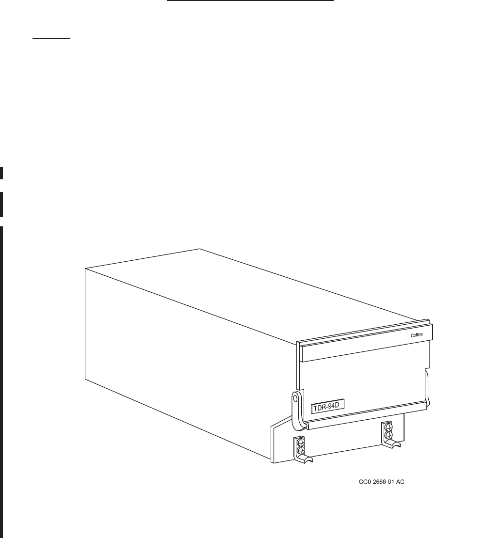
ROCKWELL COLLINS
COMPONENT MAINTENANCE MANUAL with IPL
TDR-94, PART NO 622-9352
DESCRIPTION AND OPERATION
TASK 34-50-96-870-801-A01
1. General
A. The TDR 94/94D ATC/Mode S Transponder is a solid state, airborne, air traffic control (ATC)
transponder that responds to ATCRBS (Air Traffic Control Radar Beacon System) Mode A
and Mode C interrogations as well as Mode S (Mode Select) interrogations. The Mode-S
transponder differs from earlier ATCRBS transponders in the capability of responding to
discretely addressed interrogations and by the capability of receiving and sending data
link communications. The TDR 94D Mode S Transponder is also capable of operating
through either of two antennas for use in diversity installations for air to air surveillance
and communications.
B. Figure 1/GRAPHIC 34-50-96-99B-001-A01 shows an overall view of the equipment. Table
1/Table 34-50-96-99A-001-A01 is a list of equipment covered in this manual. Table 2/Table
34-50-96-99A-002-A01 is a list of related publications. Table 3, Abbreviations and Symbols,
has been moved to the Introduction section of this manual.
TDR-94/94D ATC Mode S Transponder
Figure 1/GRAPHIC 34-50-96-99B-001-A01
34-50-96 Page 1
May 18/06

ROCKWELL COLLINS
COMPONENT MAINTENANCE MANUAL with IPL
TDR-94, PART NO 622-9352
EQUIPMENT
TYPE DESCRIPTION COLLINS PART
NUMBER
TDR-94 TDR-94 Mode A, C, and S transponder primarily for non-TCAS
applications; including CLASS 3A Automatic Dependent
Surveillance-Broadcast (ADS-B) capability. The -005 unit
is the same as the -004 unit but has improved software
to properly report altitude resolution, when the altitude
data is derived from a Gillham-based altitude encoder.
The -006 is the same as a -005 but has improved software to
prevent non-Collins TCAS systems displaying a TCAS flag, or
intermittent TCAS flag, when the TCAS is in the Standby mode.
The -007 unit has the capability to process aircraft Flight
Identification inputs and to support expanded ground station
Surveillance Identifier (SI) codes.
The -008 status provides Elementary and Enhanced
Surveillance functionality for Proline4/21 integrated systems
that use IOC-851A, 3100, 4000, or 4100 Input/Output
Concentrators. The -008 status may also be used in
non-integrated installations.
The -108 status is the same as the -008 but adds Automatic
Dependent Surveillance-Broadcast (ADS-B) functionality.
The -207, -308 and -408 is the same as the -007, -008, and
-108 respectively but adds GAMA Label 102G "Selected
Altitude" compatibility.
622-9352-004, -005,
-006, 007, -008, -108,
-207, -308, -309,
-310, -408, -409, -410
TDR-94D
(Cont)
TDR-94D Mode A, C, and S diversity transponder with full TCAS
compatibility features; including CLASS 3A/ADS-B capability.
The -005 unit is the same as the -004 unit but has improved
software to properly report altitude resolution, when the
altitude data is derived from a Gillham-based altitude encoder.
The -006 is the same as a -005 but has improved software to
prevent non-Collins TCAS systems displaying TCAS flag, or
intermittent TCAS flag, when the TCAS is in the Standby mode.
622-9210-004, -005,
-006, -007, -008,
-108, -207, -308,
-309, -310, -408,
-409, -410
Equipment Covered Cont.
Table 1/Table 34-50-96-99A-001-A01
34-50-96 Page 2
May 20/10

ROCKWELL COLLINS
COMPONENT MAINTENANCE MANUAL with IPL
TDR-94, PART NO 622-9352
EQUIPMENT
TYPE DESCRIPTION COLLINS PART
NUMBER
TDR-94D
(Cont)
The -007 unit has the capability to process aircraft
Flight Identification inputs and to support expanded
ground station Surveillance Identifier (SI) codes.
The -008 status provides Elementary and Enhanced
Surveillance functionality for Proline 4/21 integrated systems
that use IOC-851A, 3100, 4000, or 4100 Input/Output
Concentrators. The -008 status may also be used in
non-integrated installations.
The -108 status is the same as the -008 but adds Automatic
Dependent Surveillance-Broadcast (ADS-B) functionality.
The -207, -308, and -408 is the same as the -007, -008, and
-108 respectively but adds GAMA Label 102G "Selected
Altitude" compatibility.
Equipment Covered
Table 1/Table 34-50-96-99A-001-A01
PUBLICATION ATA NO COLLINS PART
NUMBER
Rockwell Collins Avionics Standard Shop Practices Manual, Instruction
Manual
None 523-0768039
Collins Pro Line II Comm/Nav/Pulse System, Installation Manual None 523-0772719
Collins TDR-94/94D Mode S Transponder System, Instruction Book
(Flightline Maintenance)
None 523-0775652
Collins CTL-92T TCAS Control, Component Maintenance Manual 34-40-84 523-0776595
Collins RTU-870A/870T Radio Tuning Unit, Component Maintenance
Manual
23-80-80 523-0774068
Collins CTL-X2/X2A/22C Controls, Instruction Book (Repair Manual) 23-80-80 523-0772495
Related Publications
Table 2/Table 34-50-96-99A-002-A01
Table 3/Table 34-50-96-99A-003-A01 ** Deleted **
34-50-96 Page 3
May 07/07

ROCKWELL COLLINS
COMPONENT MAINTENANCE MANUAL with IPL
TDR-94, PART NO 622-9352
TASK 34-50-96-870-802-A01
2. Purpose of Equipment
A. The TDR-94/94D ATC/Mode S Transponder is the airborne transponder for ATCRBS and
provides the data link processing function for ATC. The TDR-94/94D provides mode A, mode
C, and special identification replies to ATCRBS interrogations for tracking, identification,
and altitude reporting purposes. In addition, the TDR-94/94D is capable of receiving and
sending mode S message formats that will be required for air traffic control automation. The
added data link capability allows the transponder to perform additional air traffic control
and airplane separation assurance (ASA) functions. In mode S operation each airplane is
assigned a unique address code. This code can be used to direct interrogations to a specific
airplane. The reply also contains this unique address to identify the sending airplane.
TASK 34-50-96-870-803-A01
3. Equipment Specifications
A. Table 4/Table 34-50-96-99A-036-A01 lists the environmental and equipment specifications
for the TDR-94/94D Transponder.
CHARACTERISTIC SPECIFICATION
Certification
TSO
FAA TDR-94
TSO-C112, 3A2, 121, 010
TDR-94D
TSO-C112, 3A2, 121, 011
RTCA DO-181A (through change 2c “TCAS Change No. 7 Compatibility”), DO-144
Software, RTCA DO-178A (Level 2), DO-178B (Level B)
Software, EUROCAE ED-12A, ED-12B
Deutsche Bundespost FTZ A44652010
ICAO Annex 10
Environmental
RTCA DO-160C, refer to Table 5/Table 34-50-96-99A-037-A01 for additional
information
EUROCAE ED-14B
Physical
Equipment Specifications Cont.
Table 4/Table 34-50-96-99A-036-A01
34-50-96 Page 4
May 18/06

ROCKWELL COLLINS
COMPONENT MAINTENANCE MANUAL with IPL
TDR-94, PART NO 622-9352
CHARACTERISTIC SPECIFICATION
Size
Height 84.6 mm (3.33 in)
Width 124.5 mm (4.90 in)
Length 353.2 mm (13.91 in)
Weight 3.8 kg (8.5 lb)
Mounting MMT-150 Mounting Tray; 1/2 ATR, short, dwarf (Refer to Pro Line II
Comm/NAV/Pulse Installation Manual for additional information.)
Mating Connector Thinline II, qty 2, 60-pin (Kits: CPN: 628-8661-001/002 or 628-8660-001/002)
(Refer to Pro Line II Comm/Nav/Pulse Installation Manual for additional
information.)
Cooling Convection
If installed transponder is in an enclosed area with minimum air flow, it is
advisable for the installer to mount a small fan in the vicinity to generate air flow
around the unit. Although not required, use of the fan will result in reduced
component temperatures and corresponding increase in reliability.
Time between overhaul On condition of failure or as required by Federal Regulations (see example
below), other regulations may apply. Consult appropriate regulatory documents
and agencies for complete information.
Regulatory requirement for
flightline test
FAR 91.413 ATC TRANSPONDER TESTS AND INSPECTIONS.
"(a) No person may use an ATC transponder that is specified in Part 125
§91.24 (a), §121.345, §127.123 (b), or §135.143 (c) of this chapter unless,
within the preceding 24 calendar months, that ATC transponder has been
tested and inspected and found to comply with Appendix F of Part 43 of this
chapter; and following any installation or maintenance on an ATC transponder
where data correspondence error could be introduced, the integrated system
has been tested, inspected, and found to comply with paragraph Appendix
E of Part 43 of this chapter."
Power requirements 27.5 ±2.5 V dc at 28 watts nominal, 100 watts peak
Transmitter
Frequency 1090 ±1 MHz
Power output 250 watts min and 625 watts max (measured at the unit’s antenna connector
terminated into a 50-ohm resistive load.)
Load impedance 50 nominal
VSWR 1.5:1 service max; 3:1 survival
Receiver
Equipment Specifications Cont.
Table 4/Table 34-50-96-99A-036-A01
34-50-96 Page 5
May 18/06

ROCKWELL COLLINS
COMPONENT MAINTENANCE MANUAL with IPL
TDR-94, PART NO 622-9352
CHARACTERISTIC SPECIFICATION
Frequency 1030 ±0.2 MHz from ATCRBS interrogators and
1030 ±0.01 MHz from Mode-S interrogators
IF 60 MHz nominal
Sensitivity 73 dBm ±4 dBm
Reply modes ATCRBS mode A
ATCRBS mode C
ATCRBS mode A/Mode S All Call
ATCRBS mode C/Mode S All Call
Mode S, short (56-bit)
Mode S, long (112-bit)
Reply rate
ATCRBS 500 15-pulse replies/sec, or
1200 15-pulse replies in 100 ms - burst
Equipment Specifications Cont.
Table 4/Table 34-50-96-99A-036-A01
34-50-96 Page 6
May 18/06

ROCKWELL COLLINS
COMPONENT MAINTENANCE MANUAL with IPL
TDR-94, PART NO 622-9352
CHARACTERISTIC SPECIFICATION
Mode S 50 short including 16 long replies in 1 sec, or
18 short including 6 long replies in 100 ms, or
8shortincluding4longrepliesin25ms,or
4 short including 2 long in 1.6 ms
ATCRBS SLS
Max of 10% replies and sls
initiated
P1 pulse is MTL +3 dB to -21 dBm and
P2 equal to or greater than P1
Max of 10% replies and sls
may be initiated
P1 pulse is MTL to MTL +3 dB and
P2 equal to or greater than P1
Minimum of 90% replies
andnosls
P1 pulse is MTL +3 dB to -21 dBm, and
P1 pulse is min of 9 dB greater than P2
No P2 pulse occurs at 2.0 ±0.7 ȝs after leading edge of P1, or
P2 pulse duration is less than 0.3 ȝs
Mode S side lobe
suppression
Max of 10%
Electrical
Primary power (P1-58) 27.5, ±2.5, V dc
Primary power common
(P1-60)
27.5 V dc common
Data bus:
CSDB:
Structure 8-bits/byte, 6-bytes/block
Rate 12.5 kbps, 10-frames/s nominal, 18-blocks/frame max
Data blocks (All labels are in hexadecimal form.)
A0: altitude data; input
1E: ATC code/altitude; input or output
1F: ATC data; output
F3: diagnostic data; output
ARINC 429:
Structure 8-bits/byte, 4-bytes/word
Rate 5-words/sec min
Equipment Specifications Cont.
Table 4/Table 34-50-96-99A-036-A01
34-50-96 Page 7
May 18/06

ROCKWELL COLLINS
COMPONENT MAINTENANCE MANUAL with IPL
TDR-94, PART NO 622-9352
CHARACTERISTIC SPECIFICATION
Data labels (All labels are in octal form.)
*013: TDR and TCAS control, input/output
*015: Altitude select limits, input/output
*016: Mode S control, input/output
*031: ATC Transponder Control, input/output
*200: Gillham altitude encoder data, input/output
*203: TDR altitude data to TCAS, input/output
204: TDR corrected barometric altitude to TCAS, output
272: TCAS coordination data, part 1, output
273: TCAS data for downlink message formats 16, 20, 21, input
274: TCAS coordination data, part 2, output
274: TCAS data for downlink message formats 0 and 16, input
275: TCAS control, part 1, output
275: TCAS acknowledge, input
276: TCAS control, part 2, output
277: TCAS acknowledge, input
277: Diagnostic data request, input
350: Maintenance data, output
352: Control maintenance word pass-through
371: Equipment ident, output
* These labels are normally echoed and/or passed through to the TCAS as
received, except for the SSM which may be different depending on the state of
the transponder.
Tuning inputs Monitored only if Burst Mode (P2-59) is not selected; i.e., P2-59 is open
P2-31
P2-32
CSDB, A
CSDB, B
P2-17
P2-18
ARINC 429, A (tune input port A)
ARINC 429, B (tune input port A)
P2-13
P2-14
ARINC 429, A (tune input port B)
ARINC 429, B (tune input port B)
P2-21
P2-22
ARINC 429, A (tune input port C)
ARINC 429, B (tune input port C)
P2-27*
P2-28*
*ARINC 429, A (FMS/IRS data in)
*ARINC 429, B (FMS/IRS data in)
P2-39*
P2-40*
*ARINC 429, A (AIS/ADS data in)
*ARINC 429, B (AIS/ADS data in)
P2-49*
P2-50*
*ARINC 429, A (GPS data in)
*ARINC 429, B (GPS data in)
Equipment Specifications Cont.
Table 4/Table 34-50-96-99A-036-A01
34-50-96 Page 8
May 18/06

ROCKWELL COLLINS
COMPONENT MAINTENANCE MANUAL with IPL
TDR-94, PART NO 622-9352
CHARACTERISTIC SPECIFICATION
*These busses can be
set for low speed (12.5
kHz) or high speed (100
kHz) operation using
their associated low/high
speed selection straps
(see Chart 1).
Chart 1. Low/High Speed Bus Selection.
Bus Name Bus Pins Strap Name Strap Pin GND
GPS Data In J2-49/50 GPS_Lo/Hi_Sel J1-18 High Speed
FMS/IRS Data In J2-27/27 FMS/IRS_Lo/Hi_Sel J1-24 High Speed
AIS/ADS Data In J2-39/40 AIS/ADS_Lo/Hi_Set J1-57 High Speed
Altitude inputs
P2-33
P2-34
CSDB, A (altitude input port A)
CSDB, B (altitude input port A)
P2-35
P3-36
CSDB, A (altitude input port B)
CSDB, B (altitude input port B)
P2-25**
P2-26**
ARINC 429/575, A (altitude input port A)
ARINC 429/575, B (altitude input port A)
P2-29**
P2-30**
ARINC 429/575, A (altitude input port B)
ARINC 429/575, B (altitude input port B)
** On the -008/-108
statuses only, the Altitude
Port A/B High Speed
Select discrete input
(P1-26) selects the bus
speed (100 or 12.5 kbps).
Data outputs
P2-23
P2-24
CSDB, A (Bus 1)
CSDB, B (Bus 1)
P2-15
P2-16
ARINC 429, A (Port A)
ARINC 429, B (Port B)
P2-19
P2-20
ARINC 429, A (Port A)
ARINC 429, B (Port B)
Equipment Specifications Cont.
Table 4/Table 34-50-96-99A-036-A01
34-50-96 Page 9
May 18/06

ROCKWELL COLLINS
COMPONENT MAINTENANCE MANUAL with IPL
TDR-94, PART NO 622-9352
CHARACTERISTIC SPECIFICATION
Peripheral data
P2-1
P2-2
ARINC 429, A (Comm A/B input)
ARINC 429, B (Comm A/B input)
P2-3
P2-4
ARINC 429, A (Comm A/B output)
ARINC 429, B (Comm A/B output)
P2-5
P2-6
ARINC 429, A (Comm C/D input)
ARINC 429, B (Comm C/D input)
P2-7
P2-8
ARINC 429, A (Comm C/D output)
ARINC 429, B (Comm C/D output)
P2-9
P2-10
ARINC 429, A (TCAS coord data input)
ARINC 429, B (TCAS coord data input)
P2-11
P2-12
ARINC 429, A (TCAS coord data output)
ARINC 429, B (TCAS coord data output)
Discrete inputs
P1-1
P1-2
P1-3
P1-4
P1-5
P1-6
P1-7
P1-8
P1-9
P1-10
P1-11
P1-12
B4, ARINC 572 altitude input
B2, ARINC 572 altitude input
B1, ARINC 572 altitude input
A4, ARINC 572 altitude input
A2, ARINC 572 altitude input
A1, ARINC 572 altitude input
D4, ARINC 572 altitude input
D2, ARINC 572 altitude input
C4, ARINC 572 altitude input
C2, ARINC 572 altitude input
C1, ARINC 572 altitude input
Common, ARINC 572 altitude input
Equipment Specifications Cont.
Table 4/Table 34-50-96-99A-036-A01
34-50-96 Page 10
May 18/06

ROCKWELL COLLINS
COMPONENT MAINTENANCE MANUAL with IPL
TDR-94, PART NO 622-9352
CHARACTERISTIC SPECIFICATION
Mode S address discretes
P1-32
P1-33
P1-34
P1-35
P1-36
P1-37
P1-38
P1-39
P1-40
P1-41
P1-42
P1-43
P1-44
P1-45
P1-46
P1-47
P1-48
P1-49
P1-50
P1-51
P1-52
P1-53
P1-54
P1-55
P1-56
Common
B1
B2
B3
B4
B5
B6
B7
B8
B9
B10
B11
B12
B13
B14
B15
B16
B17
B18
B19
B20
B21
B22
B23
B24
Single discrete straps
P2-51 Antenna, dual/single select (gnd = single bottom antenna used and all diversity
functions are inhibited)
P2-56 CSDB/ARINC 429 control select (gnd = CSDB control bus is selected for
control of data input)
P2-60 ADLP select (gnd = ADLP included in installation)
P1-13 TCAS installed (gnd = TCAS included in installation)
NOTE: There is no provision for TCAS control in CSDB. Therefore, the
TDR-94D will not report TCAS capability in its replies to interrogations
when CSDB is enabled (P2-56 grounded), even if TCAS is selected
(P1-13 grounded) and dual antenna enabled (P2-51 open).
Equipment Specifications Cont.
Table 4/Table 34-50-96-99A-036-A01
34-50-96 Page 11
May 18/06

ROCKWELL COLLINS
COMPONENT MAINTENANCE MANUAL with IPL
TDR-94, PART NO 622-9352
CHARACTERISTIC SPECIFICATION
P1-17 (-004 thru -007
status only)
IRS enable (gnd = transponder uses IRS/FMS data input on P1-2-27 and
P2-28)
P1-17 (-008/-108 status
only)
Configuration select 1 (See Combination Discretes below)
P1-18 GPS Lo/Hi speed select (gnd = enables the transponder to send high speed
DGPS information to an on-board GNNS receiver via the Comm-C/D Output
bus (P2-7 and P2-8) using a modified Williamsburg protocol).
P1-19 (-004 thru -007
status only)
MSSS enable (gnd = transponder is enables to perform Mode-S specific
functions)
Functional I/O
P2-55 Standby discrete (gnd = in standby)
P1-28 (-004 thru -007
status only)
Automatic altitude select enable (gnd = auto alt select enabled)
P1-28 (-008/-108 status
only)
Configuration select 0 ( See Combination Discretes below)
P1-14 Control Altitude Select (See Combination Discretes below) (gnd = port A
altitude data supplied on control port, port B same as open), (open = ports A
and B altitude selectable via altitude type select discretes, P2-41/42)
P2-53 Air/ground discrete #1 (gnd = WOW); continue replying to all interrogations
while on the ground.
P1-27 Air/ground discrete #2 (gnd = WOW); inhibit replies to ATCRBS,
ATCRBS/Mode-S All-call, and Mode-S only All-call interrogations when on
the ground
P2-48 Reporting altitude port select (gnd = port B)
P2-59 Burst tune enable (gnd = burst)
NOTE: In Burst Tune mode the control port strapping (P2-57/58) is ignored.
Burst tune data is accepted on ports A, B, and C as 30 ARINC-429
words spaced over an interval of 1.5 seconds with 500 msec dwell
time on each port (dwell time is suspended when data is present).
Continuous data is always accepted if available. If continuous data is
available on part B, then the burst data on ports A and C will be ignored.
Equipment Specifications Cont.
Table 4/Table 34-50-96-99A-036-A01
34-50-96 Page 12
May 18/06

ROCKWELL COLLINS
COMPONENT MAINTENANCE MANUAL with IPL
TDR-94, PART NO 622-9352
CHARACTERISTIC SPECIFICATION
P1-15
P1-30
Cross-side input (connected to opposite TDR P1-30, gnd input = command to
standby)
Cross-side output (connected to opposite TDR P1-15, gnd output = active
mode)
(These connections are used in dual burst-tune TDR installations to ensure that
only one transponder is operating at a time)
P1-31 Fault monitor output (28 V dc = valid, 200 mA max)
P1-26 (-004 thru -007
status only)
Acquisition squitter inhibit (when grounded, this discrete commands the
transponder to stop executing the acquisition squitter (DF=11) function).
P1-26 (-008/ -108 status
only)
Altitude port A/B high speed select. When ground, the transponder accepts
altitude data from altitude ports A and B at a 100 kbps rate. When open, the
transponder accepts altitude data from altitude ports A and B at a 12.5 kbps
rate.
P1-59 Extended squitter disable discrete input (gnd = transponder must not perform
the extended squitter functions but it must continue to perform all required
acquisition squitter functions; open = transponder must perform all extended
squitter functions as well as all acquisition squitter functions.)
P1-29 Suppression input/output pulse (connected to all other L-band equipment)
P1-25 Suppression shield (this pin is used for proper termination of suppression
input/output shield)
P1-16 SPI (remote ident) input (gnd = ident on)
Maintenance specific:
P2-38 (-004 thru
-007 status)
P1-19 (-008/-108 status)
Self-test inhibit (gnd = all self-test and squitter functions are inhibited) (for
maintenance purposes only)
P2-37, 38 (-008/-108
status)
GPS time tag high and low inputs (respectively). This differential input pair is
conditioned on the CPU-I/O card to provided a positive-going pulse to the
NMIinputoftheCPU.
P2-54 (-004 thru -008
status)
Self-test discrete (gnd = enable self-test or diagnostic mode) (for bench
test/maintenance purposes only)
P2-54 (-108 status) ADS-B SIL Designator
Equipment Specifications Cont.
Table 4/Table 34-50-96-99A-036-A01
34-50-96 Page 13
May 18/06

ROCKWELL COLLINS
COMPONENT MAINTENANCE MANUAL with IPL
TDR-94, PART NO 622-9352
CHARACTERISTIC SPECIFICATION
Combination discrete
straps: P1-14,
P2-41, P2-42, )
(-004thru-007status
only)
P1-14 P2-41 P2-42 Altitude Type Selected
open gnd gnd ARINC 429 on ARINC ports A and B
open open gnd CSDB on CSDB ports A and B
open gnd open ARINC 575 on ARINC ports A and B
open open open ARINC 572 (Gillham) on the Gillham parallel port
gnd gnd gnd Port A altitude on the selected control bus
(either ARINC 429 or CSDB) and port B altitude
type ARINC 429 on ARINC port B.
gnd open gnd Port A altitude on the selected control bus
(either ARINC 429 or CSBB) and port B altitude
type CSDB on CSDB port B.
gnd gnd open Port A altitude on the selected control bus
(either ARINC 429 or CSDB) and port B altitude
type ARINC 575 on ARINC port B
gnd open open Port A altitude on the selected control bus
(either ARINC 429 or CSDB) and port B altitude
type Gillham on the Gillham parallel port.
Combination discrete
straps: P1-17, P1-28,
P2-41, P2-42 )
(-008/-108 status only)
P2-42 P2-41 P1-17 P1-28 Configuration Selected
See Note 1 Open Open Standard TDR Configuration per
-007 and Note 6
See Note 1 Open Ground Standard TDR Configuration with
GAMA 429 FMS (ignores label 335)
Ground Open Ground Open Proline 4/21 Concentrated Inputs
on FMS/IRS and AIS/ADS Buses.
A dual AHS installation is indicated
when P2-42 is ground
Ground Ground Ground Open Proline 4/21 Concentrated Inputs
on FMS/IRS and AIS/ADS Buses.
A ground on P2-41 disables GPS
data on the FMS/IRS and AIS/
ADS Buses. GPS data is then
accepted only on the GPS and A429
Altitude Port B inputs (P2-29, 30).
When P2-41 is open circuit, GPS
selection is restricted.
A dual AHS installation is indicated
when P2-42 is ground
Open Open Ground Open Proline 4/21 Concentrated Inputs
on FMS/IRS and AIS/ADS Buses.
A tripple installation is indicated
with P2-42 open circuit.
Equipment Specifications Cont.
Table 4/Table 34-50-96-99A-036-A01
34-50-96 Page 14
May 18/06

ROCKWELL COLLINS
COMPONENT MAINTENANCE MANUAL with IPL
TDR-94, PART NO 622-9352
CHARACTERISTIC SPECIFICATION
Open Ground Ground Open Proline 4/21 Concentrated Inputs
on FMS/IRS and AIS/ADS Buses.
A ground on P2-41 disables GPS
data on the FMS/IRS and AIS/
ADS Buses. GPS data is then
accepted only on the GPS and A429
Altitude Port B inputs (P2-29, 30).
WhenP2-41isopencircuit,GPS
selection is restricted.
A tripple installation is indicated
with P2-42 open circuit.
See Note 1 Ground Ground Reserved for future configuration
assignment.
Notes:
1. When Config Sel 1 and 0 are '00' or '01', the standard TDR configuration
is selected and Altitude Sel 1 or 0 function in the normal manner to
select the altitude type provided to the altitude ports. When Config Sel
1 and 0 are '10', concentrated inputs supply data to the transponder. In
this configuration, altitude data (labels 203 and 204) is supplied to the
transponder via the selected control bus or the concentrated inputs. All
other air data parameters are provided on the concentrated buses. The
Control/Altitude Select input (P1-14) controls whether the transponder
accepts altitude data from the Selected Control Bus or as directed by the
Config Sel 0 and 1 discretes. When the configuration discrete inputs indicate
that all other altitude data is accepted via the concentrated buses, the altitude
select discrete inputs are not needed and can be reassigned to other select
functions. No configuration is currently assigned to configuration select input
of '11'. This is reserved for a future configuration assignment.
2. Note that configuration discretes P1-17 and P1-28 are logic 1 with the input
grounded and logic 0 with the input open circuit.
3. Note that altitude select discretes P2-42 and P2-41 are logic 1 with the input
open circuit and logic 0 with the input grounded.
4. The -008 and -108 status TDR-94/94D adds the following capabilities to the
standard configuration:
ವLow/high speed selection of the ARINC 429 Altitude Port A and B inputs.
ವAcceptance of label 102 via the ARINC 429 Altitude Port A and B inputs.
Standard TDR Configuration for the -007 status release is defined in the above
row (labelled -004 thru -007 status only) by discrete straps P1-14, P2-41, and
P2-42.
Equipment Specifications Cont.
Table 4/Table 34-50-96-99A-036-A01
34-50-96 Page 15
May 18/06

ROCKWELL COLLINS
COMPONENT MAINTENANCE MANUAL with IPL
TDR-94, PART NO 622-9352
CHARACTERISTIC SPECIFICATION
GAMA Configuration:This configuration is the same as the standard TDR
Configuration for the -007 status release, except that the transponder will not
accept label 335, since the data contained in this label does not represent track
angle rate in the GAMA configuration.
P2-43, P2-44, P2-45 Max airspeed programming (gnd to P2-52)
P2-43 P2-44 P2-45 Definition
open open open none selected
gnd open open 0 to 75 knots
open gnd open 75 to 150 knots
gnd gnd open 150 to 300 knots
open open gnd 300 to 600 knots
gnd open gnd 600 to 1200 knots
open gnd gnd more than 1200 knots
gnd gnd gnd (not defined)
P2-46, P2-47 SDI input (gnd to P2-52)
P2-46 P2-47 Definition
open open (not used)
open gnd side 1
gnd open side 2
gnd gnd (not used)
P2-57, P2-58 Control port select (gnd to P2-52)
P2-57 P2-58 Definition
gnd open Port A selected (P2-17, P2-18)
open open Port B selected (P2-13, P2-14)
open gnd Port C selected (P2-21, P2-22)
gnd gnd (reserved for internal self-test)
Equipment Specifications Cont.
Table 4/Table 34-50-96-99A-036-A01
34-50-96 Page 16
May 18/06

ROCKWELL COLLINS
COMPONENT MAINTENANCE MANUAL with IPL
TDR-94, PART NO 622-9352
CHARACTERISTIC SPECIFICATION
P1-22, P1-21, P1-20,
P1-23
The configuration of these pins tells the
transponder the vehicle type in which it is installed.
Chart 2. Type_X Select Straps (Type Set A)
Aircraft Type Set A (Type_3 (P1-23) = open)
Type_2 Type_1 Type_0
P1-22 P1-21 P1-20 Code Meaning
open open open 0 No aircraft type information
open open gnd 1 Small (<12 500 lb)
open gnd open 2 Medium (12 500 to 75 000 lb)
open gnd gnd 3 Large (75 000 to 190 000 lb)
gnd open open 4 Extra large (190 000 to 300 000 lb)
gnd open gnd 5 Heavy (>300 000 lb)
gnd gnd open 6 High performance
gnd gnd gnd 7 Rotor craft
Chart 3. Type_X Select Straps (Type Set B)
Aircraft Type Set B (Type_3 (P1-23) = gnd)
Type_2 Type_1 Type_0
P1-22 P1-21 P1-20 Code Meaning
open open open 0 No aircraft type information
open open gnd 1 Glider/sail plane
open gnd open 2 Lighter-than-air
open gnd gnd 3 Parachutist/skydiver
gnd open open 4 Surface vehicle
gnd open gnd 5 Fixed ground or tethered obstruction
gnd gnd open 6 Unmanned aerial vehicle
gnd gnd gnd 7 Unassigned
Equipment Specifications
Table 4/Table 34-50-96-99A-036-A01
34-50-96 Page 17
May 18/06

ROCKWELL COLLINS
COMPONENT MAINTENANCE MANUAL with IPL
TDR-94, PART NO 622-9352
CONDITIONS DO-160C PARA
NO SPECIFICATION
Temp and Altitude
Low Operating Temp
High Operating Temp
Low Storage Temp
High Storage Temp
Altitude
4.0
4.5.1
4.5.3
4.5.1
4.5.2
4.6.1
Categories 'A2' and 'E1'.
-55 °C (-67 °F)
+70 °C (+158 °F)
-65 °C (-85 °F)
+85 °C (+185 °F)
Category 'A2'. Certified for installation in a controlled
temperature location in an aircraft where pressures are no
lower than an altitude equivalent of 4600 m (15 000 ft) msl.
Category 'E1'. Certified for installation in a nonpressurized
but noncontrolled temperature location in an aircraft that is
operated at altitudes up to 21 300 m (70 000 ft) msl.
Temperature Variation 5.0 Category 'B'. Certified for installation in a controlled or
noncontrolled temperature location in the aircraft.
Humidity 6.0 Category 'B'. Certified for a Severe Humidity Environment.
Shock
Operational
Crash Safety:
Impulse
Sustained
7.0
7.2
7.3
7.3.1
7.3.2
Tested at 6 g peak (11 ±2 ms duration, 6 positions)
Tested at 15 g, 6 positions
Tested at 12 g, 6 positions
Vibration 8.0 Categories C, L, M, and Y
Category C: Certified for fuselage mounting in a fixed wing
turbojet or turbofan aircraft.
Category L: Certified for fuselage mounting in a fixed wing
aircraft having multiple reciprocating or turbopropeller
engines and a weight over 5700 kg (12 500 lb).
Category M: Certified for fuselage mounting in a fixed
wing aircraft having multiple, or a single reciprocating or
turbopropeller engines and a weight less than 5700 kg
(12 500 lb).
Category Y: Certified for fuselage mounting in piston or
turbojet rotary wing aircraft.
Explosion Proofness 9.0 Category E1: Certified for installation in an environment in
which uncovered flammable fluids or vapors exist, either
continuously or intermittently.
Waterproofness 10.0 Category X (no test required): Certified for installation
in locations not subject to falling water (including
condensation), rainwater, or sprayed water.
Environmental Qualifications Form Cont.
Table 5/Table 34-50-96-99A-037-A01
34-50-96 Page 18
May 18/06

ROCKWELL COLLINS
COMPONENT MAINTENANCE MANUAL with IPL
TDR-94, PART NO 622-9352
CONDITIONS DO-160C PARA
NO SPECIFICATION
Fluids Susceptibility 11.0 Category X (no test required): Certified for installation in
locations not exposed to fluid contamination from fuel,
hydraulic fluids, oil, solvents, etc.
Sand and Dust 12.0 Category X: (no test required): Certified for installation in
locations not subject to blowing sand and dust.
Fungus Resistance 13.0 Category F: Fungus test not performed. However, the
unit is composed entirely of non-nutrient materials and is
therefore classified as Category F.
Salt Spray 14.0 Category X: Certified for installation in locations not
subject to a salt atmosphere.
Magnetic Effect 15.0 Category Z: Unit causes a 1° deflection of an
uncompensated compass at a distance less than 0.3 m
(1.0 ft).
Power Input 16.0 Category Z: Certified for use on aircraft electrical systems
not applicable to any other category. For example, a dc
system from a variable range generator where a small
capacity or no battery is floating on the dc bus.
Voltage Spike 17.0 Category A: Certified for installation in systems where a
high degree of voltage spike protection is required.
Audio Frequency
Conducted Susceptibility -
power inputs
18.0 Category Z: Certified for use on aircraft electrical systems
not applicable to any other category. For example, a dc
system from a variable range generator where a small
capacity or no battery is floating on the dc bus.
Induced Signal
Susceptibility
19.0 Category Z: Certified for operation in systems where
interference-free operation is required.
RF Susceptibility (radiated
and conducted)
20.0 Category R: Certified for operation in systems where
bench testing is allowed to meet the high intensity radiated
field (HIRF) associated with the normal environment
intended for the unit installation.
Emission of RF Energy 21.0 Category Z: Certified for operation in systems where
interference-free operation is required.
Lightning Induced
Transient Susceptibility
22.0 Category Z3Z3: Certified for installation in a moderate
environment, such as the more electromagnetically open
areas of an aircraft composed principally of metal (e.g.,
cockpit).
Environmental Qualifications Form Cont.
Table 5/Table 34-50-96-99A-037-A01
34-50-96 Page 19
May 18/06

ROCKWELL COLLINS
COMPONENT MAINTENANCE MANUAL with IPL
TDR-94, PART NO 622-9352
CONDITIONS DO-160C PARA
NO SPECIFICATION
Lightning Direct Effects 23.0 Category X (no test required): Certified for operation in
which lightning effects are insignificant or not applicable.
Icing 24.0 Category X (no test performed): Certified for installation in
a location not subject to ice formation.
Environmental Qualifications Form
Table 5/Table 34-50-96-99A-037-A01
TASK 34-50-96-870-804-A01
4. Equipment Description
A. Mechanical Description
(1) The TDR-94/94D is a half-ATR short low rack mounted unit. Electrical connections
are made through two ThinLine II, 60-pin connectors. Refer to Table 4/Table
34-50-96-99A-036-A01, Equipment Specifications, for additional mount and mating
connector information.
(2) Refer to the Collins Pro Line II Comm/Nav/Pulse System Installation Manual,
523-0772719, for mounting and dimensional information.
(3) Figure 2/GRAPHIC 34-50-96-99B-002-A01 lists the three major subassemblies in
the TDR-94/94D. The main chassis occupies the center of the unit and includes the
high-voltage power supply card A1 at the front, the CPU-I/O card A5, and video
processor card A6 assemblies in the center-rear. One of the two main rear connectors
is mounted on each of these circuit cards. As viewed from the front, A5 is on the left
side, and A6 is on the right.
(4) The two outer subassemblies are the RFPA chassis assembly on the left and the IF
receiver chassis assembly on the right. Each of these also contains various circuit card
assemblies. These are all illustrated in Figure 2/GRAPHIC 34-50-96-99B-002-A01.
Table 6/Table 34-50-96-99A-004-A01 also gives listings showing the top level
configuration as well as the configurations of each of these major subassemblies.
34-50-96 Page 20
May 18/06
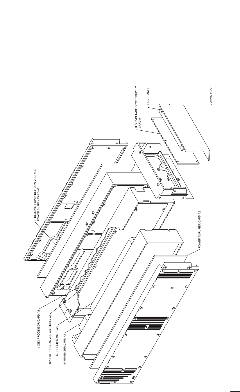
ROCKWELL COLLINS
COMPONENT MAINTENANCE MANUAL with IPL
TDR-94, PART NO 622-9352
Assembly Identification Diagram
Figure 2/GRAPHIC 34-50-96-99B-002-A01
34-50-96 Page 21/22
May 18/06

ROCKWELL COLLINS
COMPONENT MAINTENANCE MANUAL with IPL
TDR-94, PART NO 622-9352
TDR-94 Top Level, Configuration Matrix
TDR-94
622-9352- REV MAIN CHASSIS
CPN 653-2254-
RFPA CHASSIS
CPN 653-2255-
IF/RCVR/DPSK/
LVPS CHASSIS
CPN 653-2256-
004 V (SB 13) 012 004 005
004 W (SB 14) 016 004 005
004 AC 016 005 005
004 AT 016 005 006
005 AE (SB17) 018 005 005
005 AT 018 005 006
006 AG 020 005 005
006 AH 022 005 005
006 AT 022 005 006
007 AL 024 005 005
007 AT 024 005 006
008 AR 026 005 006
108 AR 028 005 006
207 BF 030 005 006
308 BJ 032 005 006
408 BJ 034 005 006
309 BM 036 005 006
409 BM 038 005 006
310 BW 040 005 006
410 BW 042 005 006
Assembly Identification Tables Cont.
Table 6/Table 34-50-96-99A-004-A01
34-50-96 Page 23
May 20/10

ROCKWELL COLLINS
COMPONENT MAINTENANCE MANUAL with IPL
TDR-94, PART NO 622-9352
TDR-94D Top Level, Configuration Matrix
TDR-94D
622-9210- REV MAIN CHASSIS
CPN 653-2254-
RFPA CHASSIS
CPN 653-2255-
IF/RCVR/DPSK/
LVPS CHASSIS
CPN 653-2256-
004 U (SB13) 011 001 005
004 V (SB 14) 015 001 005
004 AB 015 003 005
004 AK 015 006 005
004 AV 015 006 006
005 AD (SB17) 017 003 005
005 AK 017 006 005
005 AV 017 006 006
006 AG 019 003 005
006 AJ 021 003 005
006 AK 021 006 005
006 AV 021 006 006
007 AN 023 006 005
007 AV 023 006 006
008 AU 025 006 006
108 AU 027 006 006
207 BF 029 006 006
308 BJ 031 006 006
408 BJ 033 006 006
309 BM 035 006 006
409 BM 037 006 006
310 BW 039 006 006
410 BW 041 006 006
Assembly Identification Tables Cont.
Table 6/Table 34-50-96-99A-004-A01
34-50-96 Page 24
May 20/10

ROCKWELL COLLINS
COMPONENT MAINTENANCE MANUAL with IPL
TDR-94, PART NO 622-9352
Main Chassis Assembly (With SB 13 and SB 14 Installed), Configuration Matrix.
VIDEO PROC CCA A6
CPU-I/O PROG
ASSY A5
MAIN
CHASSIS CPN
653-2254-
REV HVPS CCA A1
CPN 687-0721- CPN
687-0726-
CPN
983-8019-
CPN
653-3674-
011 (-94D) AA 002 005 001
015 (-94D) - 002 004 003
015 (-94D) B 002 005 003
015 (-94D) F 003 005 003
015 (-94D) J 003 006 003
017 (-94D) - 002 005 005
017 (-94D) C 003 005 005
017 (-94D) F 003 006 005
019 (-94D) - 003 005 007
019 (-94D) C 003 006 007
021 (-94D) - 003 005 009
021 (-94D) B 003 005 011
021 (-94D) E 003 006 011
023 (-94D) - 003 005 013
023 (-94D) B 003 006 013
025 (-94D) - 003 006 015
025 (-94D) A 003 001 015
027 (-94D) - 003 006 015
027 (-94D) A 003 006 017
029 (-94D) - 003 006 019
029 (-94D) A 003 006 019
031 (-94D) - 003 001 021
033 (-94D) - 003 006 021
035 (-94D) - 003 001 023
037 (-94D) - 003 006 023
039 (-94D) - 003 001 025
041 (-94D) - 003 007 025
Assembly Identification Tables Cont.
Table 6/Table 34-50-96-99A-004-A01
34-50-96 Page 25
May 20/10

ROCKWELL COLLINS
COMPONENT MAINTENANCE MANUAL with IPL
TDR-94, PART NO 622-9352
Main Chassis Assembly (With SB 13 and SB 14 Installed), Configuration Matrix. (Cont.)
VIDEO PROC CCA A6
CPU-I/O PROG
ASSY A5
MAIN
CHASSIS CPN
653-2254-
REV HVPS CCA A1
CPN 687-0721- CPN
687-0726-
CPN
983-8019-
CPN
653-3674
012 (-94) - 002 005 002
016 (-94) - 002 004 004
016 (-94) B 002 005 004
016 (-94) E 003 005 004
016 (-94) H 003 006 004
018 (-94) - 002 005 006
018 (-94) B 003 005 006
018 (-94) E 003 006 006
020 (-94) - 003 005 008
020 (-94) D 003 006 008
022 (-94) - 003 005 010
022 (-94) B 003 005 012
022 (-94) E 003 006 012
024 (-94) - 003 005 014
024 (-94) B 003 006 014
026 (-94) - 003 001 016
028 (-94) - 003 006 016
028 (-94) A 003 006 018
030 (-94) - 003 006 020
030 (-94) A 003 006 020
032 (-94) - 003 001 022
034 (-94) - 003 006 022
036 (-94) - 003 001 024
038 (-94) - 003 006 024
040 (-94) - 003 001 026
042 (-94) - 003 007 026
Assembly Identification Tables Cont.
Table 6/Table 34-50-96-99A-004-A01
34-50-96 Page 26
May 20/10

ROCKWELL COLLINS
COMPONENT MAINTENANCE MANUAL with IPL
TDR-94, PART NO 622-9352
Programmed Assembly, Configuration Matrix
CPU-I/O PROGRAMMED
ASSEMBLY A5
PROGRAMMED
ASSEMBLY
CPU-I/O CCA
A5A1
CPN 653-3674- REV CPN 831-6270- CPN 828-2700-
001 - 002
002 - 002
003 - 002
004 - 002
005 - 002
006 - 002
007 - 007 002
008 - 007 002
009 - 008 002
010 - 008 002
011 - 009 002
012 - 009 002
013 - 010 002
014 - 010 002
015 - 003
015 B 108 003
016 - 003
016 B 108 003
017 - 003
017 A 109 003
018 - 003
018 A 109 003
019 - 011 002
019 A 011 002
020 - 011 002
020 A 011 002
021 - 110 003
022 - 110 003
Assembly Identification Tables Cont.
Table 6/Table 34-50-96-99A-004-A01
34-50-96 Page 27
Jun 20/08

ROCKWELL COLLINS
COMPONENT MAINTENANCE MANUAL with IPL
TDR-94, PART NO 622-9352
Programmed Assembly, Configuration Matrix (Cont.)
CPU-I/O PROGRAMMED
ASSEMBLY A5
PROGRAMMED
ASSEMBLY
CPU-I/O CCA
A5A1
CPN 653-3674- REV CPN 831-6270- CPN 828-2700-
023 - 111 003
024 - 111 003
025 - 112 004
026 - 112 004
RFPA Chassis Assembly, Configuration Matrix
RFPA
CHASSIS
ASSEMBLY
SYNTHESIZER
CCA A4 MODULATOR CCA A3
POWER
AMPLIFIER
CCA A2
CPN 653-2255- REV CPN 687-0724- CPN 687-0723- CPN 687-0722-
001 V 002 004 003
001 AD 002 005 003
001 AE 003 005 003
003 W 002 004 004
003 AE 003 004 004
004 Y 002 004 003
004 AE 003 004 003
005 Y 002 004 004
005 AD 002 005 004
005 AE 003 005 004
006 AC 002 005 004
006 AE 003 005 004
005 AK 003 005 004 or 006
006 AK 003 005 004 or 006
Assembly Identification Tables Cont.
Table 6/Table 34-50-96-99A-004-A01
34-50-96 Page 28
May 20/10

ROCKWELL COLLINS
COMPONENT MAINTENANCE MANUAL with IPL
TDR-94, PART NO 622-9352
IF Receiver Chassis Assembly, Configuration Matrix
IF RECEIVER
CHASSIS
IF RCVR/LVPS
CCA A7
653-2256- REV CPN 687-0727-
005 P 004
006 W 005
Assembly Identification Tables
Table 6/Table 34-50-96-99A-004-A01
B. Electrical Description
(1) Refer to Table 4/Table 34-50-96-99A-036-A01, Equipment Specifications, for detailed
listing and descriptions of all input/output signals used in the TDR-94/94D Transponder.
C. Controls and Indicators
(1) Refer to the system pilot's guide or operation section of the system installation manual
for complete descriptions of indicators and displays.
34-50-96 Page 28.1/28.2
Jun 20/08

ROCKWELL COLLINS
COMPONENT MAINTENANCE MANUAL with IPL
TDR-94, PART NO 622-9352
TASK 34-50-96-870-805-A01
5. Installation Data
A. Refer to the TDR-94/94D Installation Section in the Pro Line II Comm/Nav/Pulse System
Installation Manual for installation information relative to the TDR-94/94D Mode S
Transponder.
TASK 34-50-96-870-806-A01
6. System Theory of Operation
SUBTASK 34-50-96-870-001-A01
A. Introduction
(1) The air traffic control radar beacon system (ATCRBS) is a surveillance system in
wide use to locate and identify airplanes within an airspace. However, because of
increasing air traffic, this system is expanding to include additional facilities for airborne
collision avoidance. To gain a good understanding of Mode S transponder operation, it
is necessary to understand the operation of the existing air traffic control (ATC) system.
(2) If this is your first contact with the ATCRBS and related equipment, this paragraph
will give you an overall description of the present ATCRBS and then expand that
understanding into the new Mode S system.
SUBTASK 34-50-96-870-002-A01
B. Radar Systems
(1) Refer to Figure 3/GRAPHIC 34-50-96-99B-070-A01. The ATCRBS consists of a
primary surveillance radar (PSR) and a secondary surveillance radar (SSR). The
large rotating radar antenna that can be seen at or near most air terminals is that of
the PSR. This system uses conventional radar to locate all airplanes within its range
in terms of range and azimuth. It transmits a burst of energy and then measures the
time to an echo. The time thus measured is converted into range (refer to the note
below for additional information). The direction the antenna is pointing at the time of
echo detection establishes the azimuth to the reflecting target. This target information is
displayed Figure 3/GRAPHIC 34-50-96-99B-070-A01 on the air traffic controller's PPI
(Plan Position Indicator).
NOTE: The time is easily converted into range. The mathematical formula
for distance is: D = velocity x time. The propagation velocity of radio
energy is usually expressed as 12.359 μs / radar mile.
34-50-96 Page 29
May 18/06
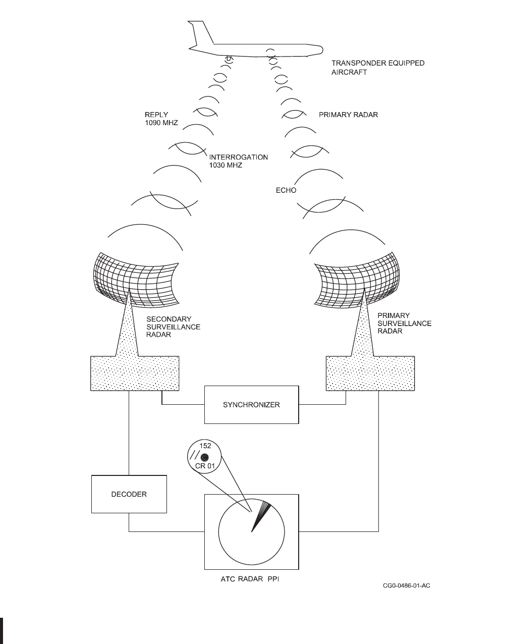
ROCKWELL COLLINS
COMPONENT MAINTENANCE MANUAL with IPL
TDR-94, PART NO 622-9352
ATCRBS, PSR and SSR System
Figure 3/GRAPHIC 34-50-96-99B-070-A01
34-50-96 Page 30
May 18/06

ROCKWELL COLLINS
COMPONENT MAINTENANCE MANUAL with IPL
TDR-94, PART NO 622-9352
SUBTASK 34-50-96-870-003-A01
C. ATCRBS Operation
(1) ATCRBS Interrogation Modes
(a) The SSR system interrogates the airplane transponder for airplane identity and
altitude. The interrogations are in the form of two modes: mode A for airplane
identity and mode C which is used to request altitude information (refer to the note
below for additional information).
NOTE: In the original definition of ATC modes, two other modes were defined;
mode B and mode D. These also differ only in pulse spacing with mode B
pulses spaced 17 μs, and mode D pulses spaced 25 μs. Mode D was
widely used in Great Britain but recently the aviation industry
has settled on mode A for ATCRBS operation and mode C for
altitude reporting. Modes B and D have been largely abandoned.
The US Military uses a system similar to ATCRBS. It is known as IFF
(Identification - Friend or Foe). As this name implies, it is concerned
primarily with mission security. Three modes are defined; modes 1, 2, and
3. Mode 3 is common to the civil mode A with a pulse spacing of 8 μs. This
allows air traffic control visibility of all airplanes, both civil and military.
(b) All pulses are 0.8 μs wide. The interrogations from the ground station are at
a frequency of 1030 MHz. The transponder replies at a frequency of 1090
MHz. The received signal from the airborne transponder is decoded by the
ground system and displayed on the ATC radar screen (see Figure 4/GRAPHIC
34-50-96-99B-071-A01). The replies produce either a single or double slash target
display on the controller screen. The controller can also elect to display the airplane
identification number (as selected by the aircrew) and altitude.
34-50-96 Page 31
May 18/06
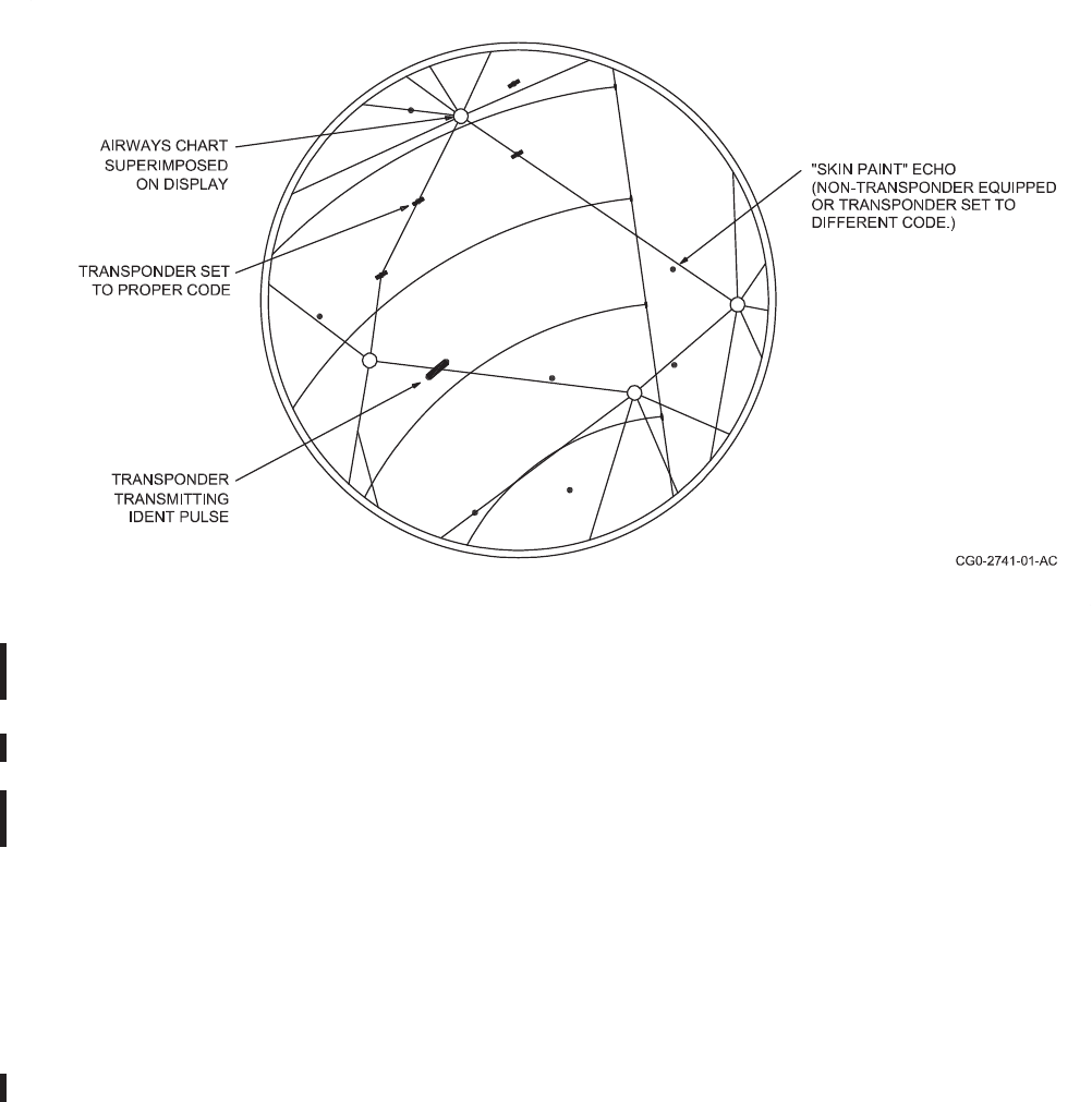
ROCKWELL COLLINS
COMPONENT MAINTENANCE MANUAL with IPL
TDR-94, PART NO 622-9352
Air Traffic Presentation on the ATC Radarscope
Figure 4/GRAPHIC 34-50-96-99B-071-A01
(2) SSR System Interrogation Description
(a) Refer to Figure 5/GRAPHIC 34-50-96-99B-072-A01 and Figure 6/GRAPHIC
34-50-96-99B-073-A01. The SSR uses a rotating directional antenna to transmit
two pulses which are identified as P1 and P3. The spacing of these pulses
determines the mode. In mode A the pulses are spaced 8 μs while in mode C
the pulses are spaced 21 μs. The SSR also uses an omnidirectional antenna to
transmit a third pulse designated P2. This pulse is transmitted 2 μs after the P1
pulse and provides a reference for side lobe suppression (SLS). The amplitude of
the P2 pulse is about the same as the peak side lobe of the directional antenna.
Ty p i c ally, this is about 18 dB below the peak of the directional (main) beam.
(b) Refer to Figure 5/GRAPHIC 34-50-96-99B-072-A01. Notice the two airplanes on
the drawing. Airplane A is shown within the main lobe of the directional antenna.
The amplitude of the P1 and P3 pulses will be substantially greater here than the
P2 pulse radiated from the omnidirectional antenna. Therefore, the transponder in
this airplane will interpret this interrogation as valid.
(c) Airplane B, however, is outside the main lobe and within one of the side lobes.
The P1 and P3 pulses detected here will be the result of side lobe radiation.
Recall that the P2 pulse is transmitted by an omnidirectional antenna and is about
34-50-96 Page 32
May 18/06

ROCKWELL COLLINS
COMPONENT MAINTENANCE MANUAL with IPL
TDR-94, PART NO 622-9352
equal in amplitude to that of the peak side lobe. Therefore, the P2 pulse detected
by airplane B will be at least as great in amplitude as the P1/P3 pulses. The
transponder in airplane B will detect this relationship in pulses and discard the
interrogation as invalid, because the P2 pulse is not substantially less than the
P1/P3 pulses. As a further safeguard against replies to late-arriving echoes to
this invalid interrogation, the transponder suppresses replies to all interrogations
for an additional 25 to 45 μs. In addition, the receiver is desensitized for reception
of P1/P3 pulses. The rationale here is that if the side lobes are detectable, then
the main lobe must be much greater.
34-50-96 Page 33
May 18/06
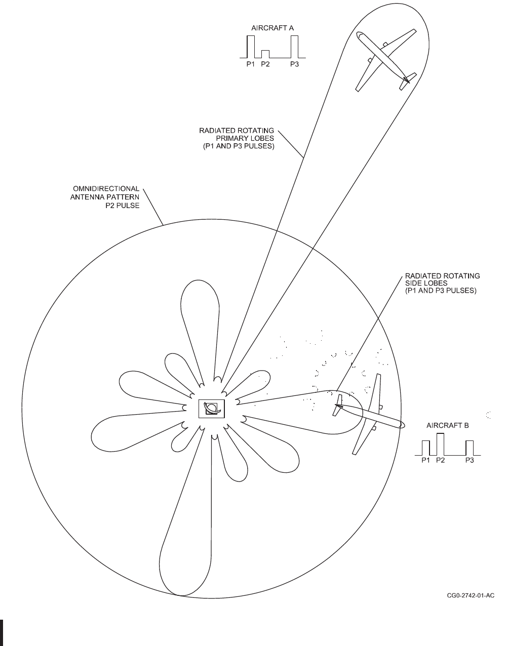
ROCKWELL COLLINS
COMPONENT MAINTENANCE MANUAL with IPL
TDR-94, PART NO 622-9352
ATCRBS, SSR Antenna Radiation Pattern
Figure 5/GRAPHIC 34-50-96-99B-072-A01
34-50-96 Page 34
May 18/06
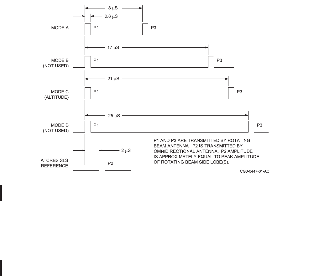
ROCKWELL COLLINS
COMPONENT MAINTENANCE MANUAL with IPL
TDR-94, PART NO 622-9352
ATCRBS Interrogator Pulse
Figure 6/GRAPHIC 34-50-96-99B-073-A01
(3) ATC Transponder Replies
(a) As mentioned earlier, the most common transponder modes are mode A and mode
C. Mode A provides ident (identification) information, while mode C provides altitude
data. The reply formats are very similar, differing only in pulse spacing (delay).
(b) The ATCRBS mode A transponder reply signal is shown in Figure 7/GRAPHIC
34-50-96-99B-074-A01. Notice that the signal can consist of from 2 to 16 pulses.
The two framing pulses F1 and F2 are always present and spaced 20.3 μs. An
identification pulse may be transmitted 4.35 μs after the last framing pulse F2. The
intervening pulses, A1 through D4, make up the coded reply. The X pulse is not
used. The coded reply consists of twelve pulses; four groupings of three pulses
each. These groupings give four digits of octal data. The digits are formed by
the sum of the pulse (bit) values; 1, 2, or 4, which can produce a digit value from
0 through 7. The A group (A1, A2, and A4) makes up the first digit, the B group
makes up the second digit, etc. (On the figure, a pulse outlined with a solid line
indicates that the pulse is present. A pulse outlined with dashed lines indicates the
position for that pulse when it is present.) The pulse configuration on the figure
indicates a reply code 1324. The first digit, 1, is formed by the presence of only the
A1 pulse. The second digit, 3, is formed by the presence of B1 and B2 (1 + 2 =
3). A digit 7 is formed when all three pulses of the group are present (1 + 2 + 4 =
34-50-96 Page 35
May 18/06
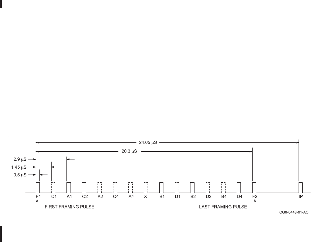
ROCKWELL COLLINS
COMPONENT MAINTENANCE MANUAL with IPL
TDR-94, PART NO 622-9352
7). Therefore, a reply sequence with all pulses present constitutes a code 7777.
The X pulse is not defined in ATCRBS replies. This combination of four digits,
each ranging from 0 through 7, makes 4096 (212) different codes possible which
explains the label 4096 code.
(c) The ATCRBS mode C transponder reply consists of the same framing pulses F1
and F2 but spaced 21 μs. The intervening pulses, A1 through D4 (except for D1),
make up the coded reply. The coding scheme is defined by ARINC 572, commonly
referred to as the Gillham code, and provides encoded altitude data in the range of
-1000 to 127 000 feet, to the nearest 100 feet. Recall that in mode A the individual
bits assume a binary value which combines into four, three-bit groups, each group
forming an octal digit. In mode C the individual pulses are combined into three
groups. The A, B, and D (except for bit D1) pulses are grouped into two four-bit
groups to encode the altitude to the nearest 500 feet. The C pulses provide the
100-feet deviation (above or below) from the 500-feet level. The mode C encoding
scheme is described in Figure 8/GRAPHIC 34-50-96-99B-075-A01. Notice that the
bit pattern does not follow a conventional binary progression. This scheme was
designed to provide a sequence in which only one bit changes at a time as the
altitude increases or decreases.
(d) The upper part of the table consists of a matrix of numbers arranged into rows
and columns. These numbers can be referred to as segment numbers. To find
the altitude to the nearest 500 feet, represented by a given bit pattern, you must
first find the segment that corresponds to that bit sequence. Multiply the segment
number by 500 and subtract 1000 (or subtract 2 from the segment number and
then multiply by 500).
(e) The 100-feet altitude is not as easy. To determine the 100-feet level, it is first
necessary to decide whether the 500-feet segment is odd or even. Knowing that,
you add or subtract 0, 100, or 200 feet to or from the 500-feet level depending on
the C bit sequence as shown in the lower portion of the table.
Transponder 4096 Reply Code, Signal Format
Figure 7/GRAPHIC 34-50-96-99B-074-A01
34-50-96 Page 36
May 18/06
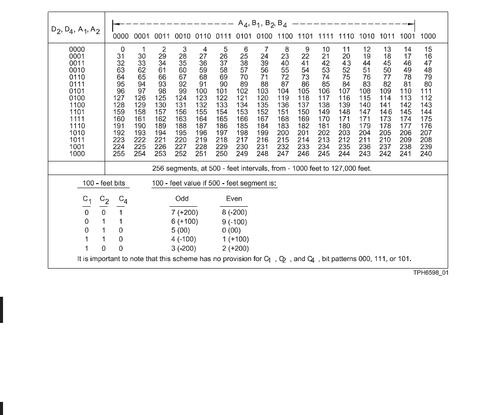
ROCKWELL COLLINS
COMPONENT MAINTENANCE MANUAL with IPL
TDR-94, PART NO 622-9352
Gillham Altitude, ARINC 572, Encoding Scheme
Figure 8/GRAPHIC 34-50-96-99B-075-A01
SUBTASK 34-50-96-870-004-A01
D. ATCRBS with Mode S
(1) Introduction
(a) Refer to Figure 9/GRAPHIC 34-50-96-99B-076-A01. Mode S substantially
enhances the capability of the ATCRBS by adding data link and select interrogation
features. The data link capability includes air to air information exchange, ground to
air (data uplink or Comm A), air to ground (data downlink or Comm B), and multisite
(ground station-to-ground station) message protocol. The mode S transponder can
also function as part of an airborne separation assurance (ASA) system when
interfaced with a Traffic alert and Collision Avoidance System (TCAS).
34-50-96 Page 37
May 18/06
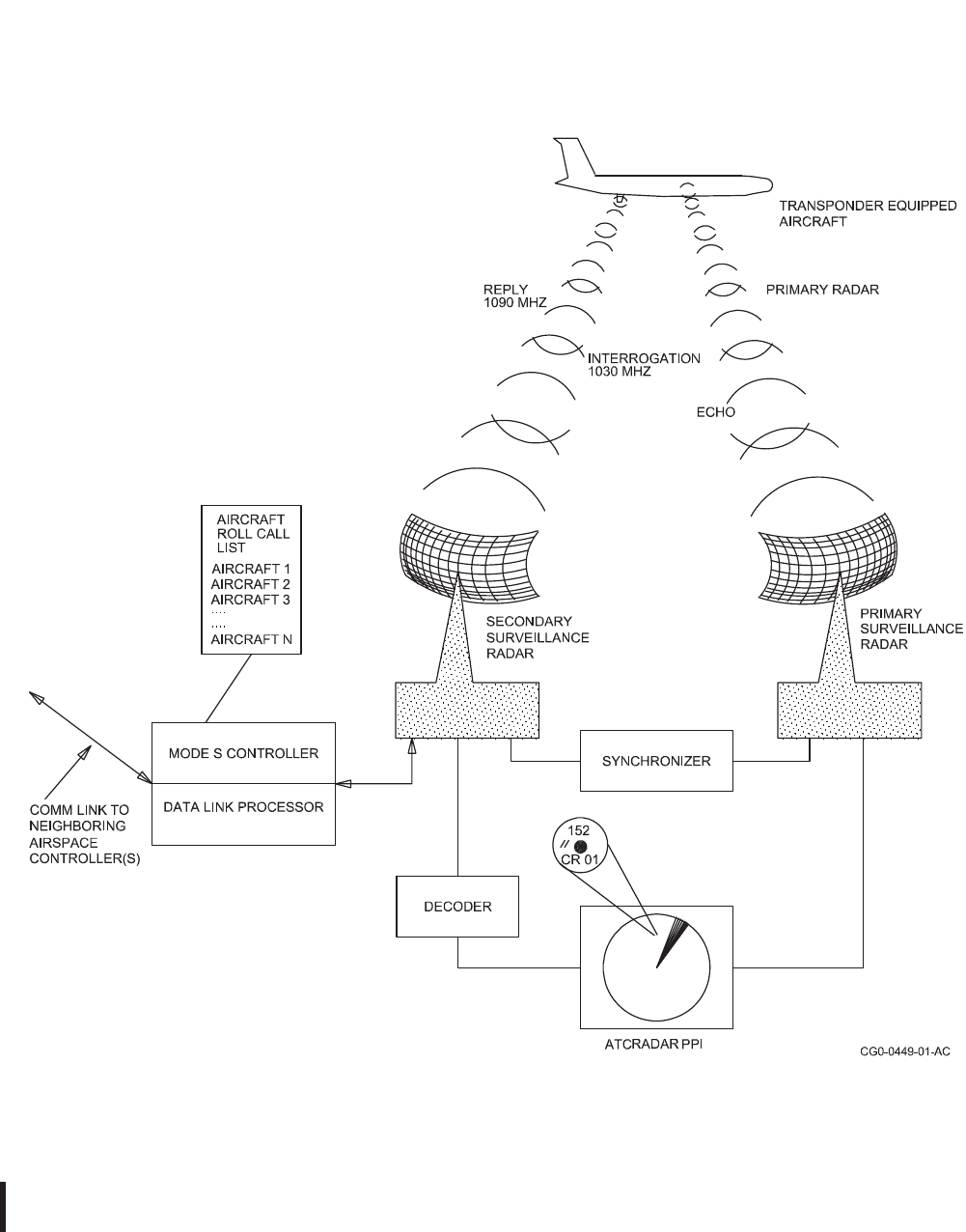
ROCKWELL COLLINS
COMPONENT MAINTENANCE MANUAL with IPL
TDR-94, PART NO 622-9352
Mode S, PSR and SSR System
Figure 9/GRAPHIC 34-50-96-99B-076-A01
34-50-96 Page 38
May 18/06

ROCKWELL COLLINS
COMPONENT MAINTENANCE MANUAL with IPL
TDR-94, PART NO 622-9352
(2) Mode S Interrogation Modes
(a) Eight different formats of interrogation are used in mode S. These eight can be
summarized as three basic types. These are shown in Figure 10/GRAPHIC
34-50-96-99B-077-A01 and Figure 11/GRAPHIC 34-50-96-99B-078-A01. Table
7/Table 34-50-96-99A-038-A01 is a summary of all eight. The three basic types
are as follows:
1Universal ATCRBS All Call
This interrogation is in the form of P1, P3, and an 0.8 μs P4 pulse. This
interrogation is recognized by all non mode S transponders in the airspace.
ATCRBS transponders reply as usual with the 4096 identification code
for mode A interrogations and altitude data for mode C. Mode S
transponders do not react to this interrogation.
2Mode S Only All Call
The second type is the same as the previous universal ATCRBS All Call
interrogation except that the P4 pulse is 1.6 μs long. This interrogation is
recognized only by mode S transponders. However, mode S transponders may
suppress replies if in the lockout condition. Mode S transponders in lockout
reply only to the select address interrogation.
3Mode S (Select) Interrogation
The third interrogation type is directed to a specific Mode-S equipped airplane.
This interrogation is in the form of P1, P2, and P6. The presence of the P2
pulse at the normal ATCRBS SLS location effectively suppresses
the non mode S transponder reply.
(b) This variety of interrogation capability gives the ground controller the flexibility of
addressing airplanes of immediate interest, as opposed to processing replies from
every airplane in the area.
(c) All of the Mode-S uplink or interrogation message formats are summarized in
Table 7/Table 34-50-96-99A-038-A01. The fields are described in the following
paragraphs. These descriptions mirror Document RTCA/DO 181 with minor
changes to clarify the text.
1Address/Parity (AP)
The 24 bit AP field contains the parity overlaid on the address. The field
appears at the end of all transmissions for uplink interrogations and downlink
replies, except for Downlink Format (DF) number 11.
2Acquisition Special (AQ)
The 1 bit AQ field designates uplink format (UF) numbers 0 and
16 as acquisition transmissions and repeats as received by the
transponder in DF numbers 0 and 16.
34-50-96 Page 39
May 18/06

ROCKWELL COLLINS
COMPONENT MAINTENANCE MANUAL with IPL
TDR-94, PART NO 622-9352
3Comm B Data Selector (BDS)
This 8 bit BDS field in UF number 1 contains the identity of the
ground-initiated Comm B register whose contents appear in the
MV field of the corresponding reply.
4Designator Identification (DI)
The 3 bit DI field identifies the coding within the special designator (SD) field in
UF numbers 4, 5, 20, and 21. The codes are defined as follows:
DI DEFINITION
0 SD contains Interrogator Identification (IIS) information. IIS data is
basically the same as the II field except that it appears as a subfield in
multisite data protocol.
1 SD contains multisite information
2 SD contains extended squitter control information
3-6 (not assigned)
7 SD contains extended data readout requests
5Interrogator Identification (II)
The 4 bit II field identifies the interrogator and appears in UF number 11 (Mode
S only all call).
6Message, Comm A (MA)
The 56 bit MA field contains messages directed to the airplane during Comm A
interrogations (UF numbers 20 and 21).
7Message, Comm C (MC)
The 80 bit MC field contains one of a sequence of segments transmitted to the
transponder in the extended length message (ELM) (112 bits) using
UF number 24.
8Message, Comm U (MU)
The 56 bit MU field contains information used in air to air message exchanges
and is part of the long special surveillance interrogation using UF number 16.
This message field does not use the Comm A protocol.
9Number of C Segment (NC)
The 4 bit NC field provides the number of a segment transmitted in an uplink
ELM message and is part of the Comm C interrogation using UF number 24.
10Protocol (PC)
The 3 bit PC field contains operating commands to the transponder
and is part of surveillance and Comm-A interrogations using UF
numbers 4, 5, 20, and 21. The codes used in this field are as follows:
34-50-96 Page 40
May 18/06

ROCKWELL COLLINS
COMPONENT MAINTENANCE MANUAL with IPL
TDR-94, PART NO 622-9352
PC DESCRIPTION
0 No changes in transponder state
1 Nonselective all call lockout
2 - 3 (not assigned)
4 Close out B
5 Close out C
6 Close out D
7 (not assigned)
11Probability of Reply (PR)
The 4 bit PR field contains commands to the transponder to specify
the reply probability to the mode S only all call interrogation, UF
number 11. A command to disregard any lockout state
can also be given. The assigned codes are as follows:
PR DESCRIPTION
0 Reply with probability = 1
1 Reply with probability = 1/2
2 Reply with probability = 1/4
3 Reply with probability = 1/8
4 Reply with probability = 1/16
5 -7 Do not reply
8 Disregard lockout, reply with probability = 1
9 Disregard lockout, reply with probability = 1/2
10 Disregard lockout, reply with probability = 1/4
11 Disregard lockout, reply with probability = 1/8
12 Disregard lockout, reply with probability = 1/16
13 -15 Do not reply
After receiving a mode S only all call containing a PR code other than 0 or 8,
the transponder will execute a random process and make a reply decision,
for this interrogation, in accordance with the command probability. Random
occurrence of replies enables the interrogator to acquire closely-spaced
airplanes whose replies would otherwise synchronously garble each other.
12Reply Control (RC)
The 2 bit RC field designates the transmitted segment as initial (0), intermediate
(1), or final (3). An RC field (3) is used to request a Comm D downlink action by
the transponder. RC is part of the Comm C interrogation, UF number 24.
13Reply Length (RL)
The 1 bit RL field commands a reply in DF number 0 if the bit is logic 0, and a
reply in DF number 16 if the bit is logic 1.
14Reply Request (RR)
The 5 bit RR field contains the length and content of the reply
34-50-96 Page 41
May 18/06

ROCKWELL COLLINS
COMPONENT MAINTENANCE MANUAL with IPL
TDR-94, PART NO 622-9352
requested by the interrogators. The RR field is part of the surveillance
and Comm A interrogations using UF numbers 4, 5, 20, and 21.
The codes used in the RR field are described as follows:
RR REPLY LENGTH MB CONTENT
0 - 15 short -------------
16 long Air-initiated Comm B
17 long Extended capability
18 long Flight ID
19 long TCAS resolution advisory report
20 - 31 long Not assigned
If the first bit of the RR code is logic 1, then the decimal equivalent of the last
four bits designates the requested source.
15Special Designator (SD)
The 16 bit SD field contains control codes affecting the transponder protocol
and is part of surveillance and Comm A interrogations using UF numbers 4, 5,
20, and 21. The content is specified by the DI field. A 4-bit IIS subfield is within
all SD fields of UF numbers 4, 5, 20, and 21 if the DI code is 0, 1, or 7. The IIS
is used to specify the interrogator identifier.
16Uplink Format (UF)
UF is a general term referring to the first field in all uplink formats and is the
transmission descriptor in all interrogations. UF refers to all messages
described in Table 7/Table 34-50-96-99A-038-A01.
FORMAT
NUMBER UPLINK BIT FORMAT
HEX/
DEC UF SHORT MESSAGE STRUCTURE MESSAGE TYPE
0 / 0 0 0000 3RL: 1 4AQ: 1 BDS:
810AP: 24
SHORT
SPECIAL (Air-Air)
SURVEILLANCE
1 / 1 0 0001 Length, content, and structure undefined AP: 24
2 / 2 0 0010 AP: 24
3 / 3 0 0011 AP: 24
NOT PRESENTLY
DEFINED
OR NOT USED
4 / 4 0 0100 PC: 3 RR: 5 DI: 3 SD: 16 AP: 24
SURVEILLANCE,
ALTITUDE
REQUEST
Mode S, Interrogation Code Summary Cont.
Table 7/Table 34-50-96-99A-038-A01
34-50-96 Page 42
May 18/06
ROCKWELL COLLINS
COMPONENT MAINTENANCE MANUAL with IPL
TDR-94, PART NO 622-9352
FORMAT
NUMBER UPLINK BIT FORMAT
5 / 5 0 0101 PC: 3 RR: 5 DI: 3 SD: 16 AP: 24
SURVEILLANCE,
IDENTITY
REQUEST
6 / 6 0 0110 Length, content, and structure undefined AP: 24
7 / 7 0 0111 AP: 24
8 / 8 0 1000 AP: 24
9 / 9 0 1001 AP: 24
A / 10 0 1010 AP: 24
NOT PRESENTLY
DEFINED
OR NOT USED
B / 11 0 1011 PR: 4 II: 4 19 (ALL ONES)AP: 24 MODE S ONLY,
ALL-CALL
C / 12 0 1100 Length, content, and structure undefined AP: 24
D / 13 0 1101 AP: 24
E / 14 0 1110 AP: 24
NOT PRESENTLY
DEFINED
OR NOT USED
F / 15 0 1111 AP: 24
LEGEND: XX: M designates a field containing M bits, Ndenotes free space with N available bits.
FIELD DESIGNATORS:
AP = Address/Parity
AQ = Acquisition Special
BDS = Comm-B Data Selector
DI = Designator Identification
II = Interrogator Identification
PC = Protocol
PR = Probability of Reply
RL = Reply Length
RR = Reply Request
SD = Special Designator
UF = Uplink Format
HEX/
DEC UF LONG MESSAGE STRUCTURE MESSAGE TYPE
01/ 16 1 0000 3RL: 1 4AQ: 1 -18- MU-56 AP: 24 LONG SPECIAL
SURVEILLANCE
11/ 17 1 0001 Length, content, and structure undefined AP: 24
12/ 18 1 0010 AP: 24
13/ 19 1 0011 AP: 24
NOT DEFINED
OR NOT USED
14/ 20 1 0100 PC: 3 RR: 5 DI: 3 SD: 16 MA: 56 AP: 24
COMM-A,
ALTITUDE
REQUEST
15/ 21 1 0101 PC: 3 RR: 5 DI: 3 SD: 16 MA: 56 AP: 24
COMM-A,
IDENTITY
REQUEST
Mode S, Interrogation Code Summary Cont.
Table 7/Table 34-50-96-99A-038-A01
34-50-96 Page 43
May 18/06

ROCKWELL COLLINS
COMPONENT MAINTENANCE MANUAL with IPL
TDR-94, PART NO 622-9352
FORMAT
NUMBER UPLINK BIT FORMAT
16/ 22 1 0110 Length, content, and structure undefined P: 24
17/ 23 1 0111 P: 24
NOT PRESENTLY
DEFINED
OR NOT USED
18/ 24
(see
note)
11 RC: 2 NC: 4 MC: 80 AP: 24
COMM-C,
EXTENDED
LENGTH
MESSAGE
LEGEND:
XX: M designates a field containing M bits, Ndenotes free space with N available bits.
NOTE:
Format number 18 / 24 is defined as the beginning with "11" in the first two bit positions while the following
three bits vary with the interrogation content; i.e., two bits are the C field and the remaining bit is in the
NC field.
FIELD DESIGNATORS:
AP = Address/Parity
AQ = Acquisition Special
DI = Designator Identification
MA = Message, Comm-A
MC = Message, Comm-C
MU = Message, Comm-U
NC = Number of C-Segment
PC = Protocol
RC = Reply Control
RL = Reply Length
RR = Reply Request
SD = Special Designator
UF = Uplink Format
Mode S, Interrogation Code Summary
Table 7/Table 34-50-96-99A-038-A01
34-50-96 Page 44
May 18/06
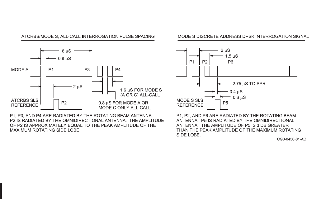
ROCKWELL COLLINS
COMPONENT MAINTENANCE MANUAL with IPL
TDR-94, PART NO 622-9352
Mode S, All-Call, and Discrete Addressing, Interrogation Format
Figure 10/GRAPHIC 34-50-96-99B-077-A01
34-50-96 Page 45
May 18/06
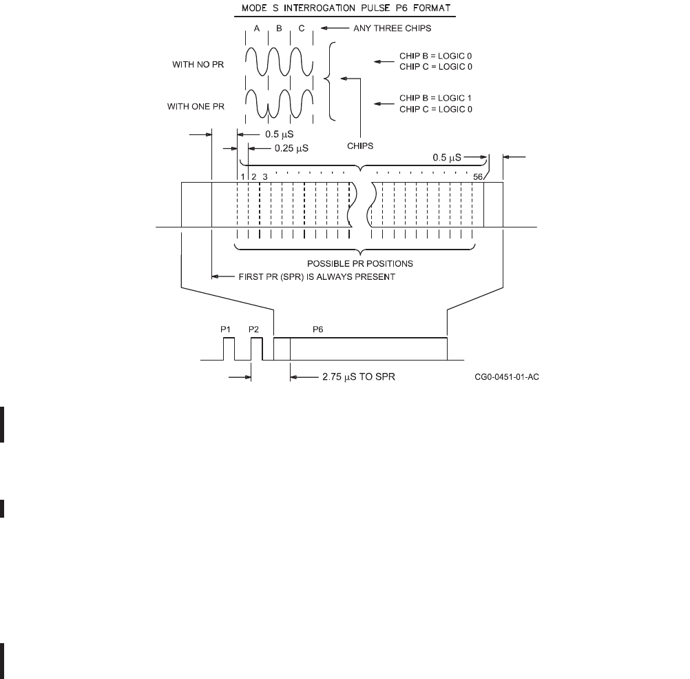
ROCKWELL COLLINS
COMPONENT MAINTENANCE MANUAL with IPL
TDR-94, PART NO 622-9352
Mode S Discrete Addressing, Pulse P6 Definition
Figure 11/GRAPHIC 34-50-96-99B-078-A01
(3) Mode S SSR Radiation Pattern and SLS
(a) Refer to Figure 12/GRAPHIC 34-50-96-99B-079-A01. In mode S, the
omnidirectional antenna transmits pulse P5 as the SLS reference pulse. The P5
pulse occurs within the P6 pulse and is timed 0.4 μs before the first spr. Thus, if the
amplitude of P5 is sufficient to blank the first spr of P6, the interrogation is most
likely from a side lobe and not from the main lobe. In this case the spr is hidden
from the transponder and the reply is suppressed.
(b) The transmission of mode S interrogation uses a technique known as binary
differential phase shift keying (DPSK). This technique is illustrated in Figure
11/GRAPHIC 34-50-96-99B-078-A01. For greater detail, refer to the information
below.
(c) The SSR mode S interrogation pulse spacing and identification is different from
earlier ATCRBS. Notice that the rotating beam transmits two different pulse
combinations. For all call interrogations, the transmitted pulses are P1, P3, and
P4. In these interrogations the SLS reference pulse P2 is transmitted by the
omnidirectional antenna as in conventional ATCRBS. The P1-to-P3 pulse spacing is
either 8 μs (for mode A) or 21 μs (for mode C), also as in ATCRBS. The P4 pulse
follows the P3 pulse by 2 μs and can be either 0.8 μs (the same as P1 and P3) or 1.6
34-50-96 Page 46
May 18/06

ROCKWELL COLLINS
COMPONENT MAINTENANCE MANUAL with IPL
TDR-94, PART NO 622-9352
μs. The pulse width of P4 determines the all-call objective. A 0.8 μs pulse is only for
non-mode S transponders, while the 1.6 μs pulse is only for mode S transponders.
(d) The mode S discrete addressing interrogation takes yet another form. For this
interrogation the rotating beam antenna transmits pulses P1, P2, and P6. P1 and
P2 are 0.8 μs pulses spaced 2 μs between leading edges. P6 is a single pulse that
is either 16.00 or 30.00 μs long. A data technique known as DPSK decodes the
information transmitted in the P6 pulse. This technique involves the detection of the
phase relationship of the signal at certain intervals. These intervals are referred to
as chips. Therefore, timing is the critical factor in this decoding process. Each chip is
defined as an unmodulated interval of 0.25 μs and may be in phase or out of phase
with the preceding chip. If it is out of phase, it is recognized as representing a bit
value of 1. A chip that is in phase with the preceding chip represents a bit value of 0.
(e) As shown in Figure 10/GRAPHIC 34-50-96-99B-077-A01, P6 begins 1.5 μs after
the start of pulse P2. At 1.25 μs after the start of P6, the first phase reversal (pr)
occurs. This first pr is identified as the sync phase reversal (spr). This spr must
be detected in order to enable a reply response. The final chip is followed by a 0.5
μs guard interval. This prevents the trailing edge of P6 from interfering with the
demodulation process.
(f) The ground mode S interrogator system uses a monopulse processing scheme to
determine the azimuth bearing to the airplane. This scheme requires only a single
reply from an airborne transponder, as opposed to the two replies necessary in the
earlier ATCRBS system to establish the azimuth to the airplane. In this scheme, the
monopulse system generates two separate patterns; a single (sum) pattern and a
dual lobe (difference) pattern. The ratio of the energy received by the sum pattern to
the energy received by the difference pattern determines the bearing of the airplane
from the antenna beam centerline. The address (derived from the reply) and
location (azimuth and range) of the mode S airplane is entered into a roll-call file.
This file can be visualized as a list of the mode S-equipped airplanes within their
assigned airspace. On a later scan, the mode S airplane is discretely addressed.
This discrete address contains a command field that is used to desensitize the mode
S transponder to further mode S all-call interrogations. This desensitization is called
Mode S Lockout. The ATCRBS-only transponders are not affected by this lockout
technique and mode S transponders continue to reply to ATCRBS interrogations.
(g) When a mode S-equipped airplane moves from one assigned airspace into another,
the first ground interrogator can communicate with the next interrogator and pass
airplane information to that second interrogator. This communication link can be via
ground lines or radio link. If this method is used, the mode S lockout is not disabled
on the affected airplane and the second interrogator will schedule discrete roll-call
interrogations for that airplane as needed. This technique makes it possible to
increase the airplane handling capacity of the ground interrogator.
34-50-96 Page 47
May 18/06

ROCKWELL COLLINS
COMPONENT MAINTENANCE MANUAL with IPL
TDR-94, PART NO 622-9352
(h) In regions where mode S interrogators are not connected via ground or radio link,
the protocol for the transponder allows it to be in mode S lockout only for those
interrogators that have the airplane on the roll-call list. This enables a second
ground interrogator to acquire an airplane into its assigned airspace using the
all-call technique as previously described.
34-50-96 Page 48
May 18/06
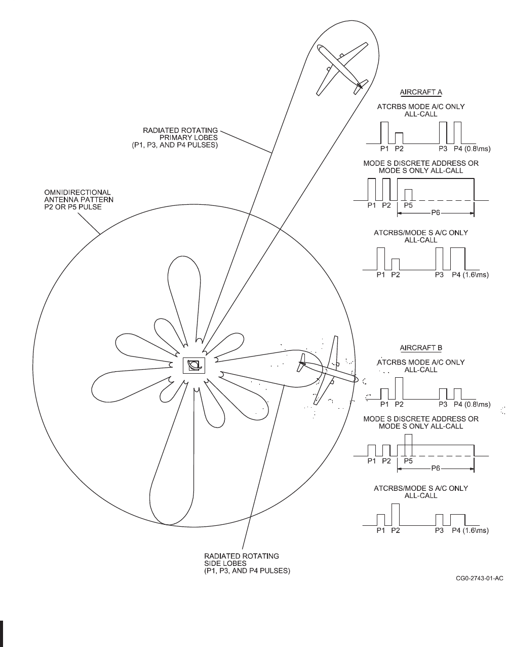
ROCKWELL COLLINS
COMPONENT MAINTENANCE MANUAL with IPL
TDR-94, PART NO 622-9352
Mode S, SSR Antenna Radiation Pattern
Figure 12/GRAPHIC 34-50-96-99B-079-A01
34-50-96 Page 49
May 18/06
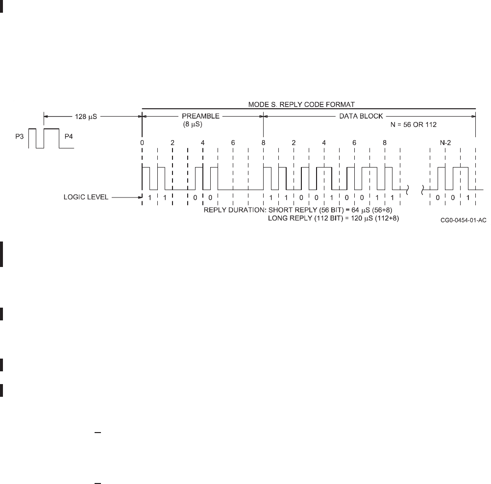
ROCKWELL COLLINS
COMPONENT MAINTENANCE MANUAL with IPL
TDR-94, PART NO 622-9352
(4) Mode S Transponder Replies
(a) Typically, the ground-based interrogator tracks an airplane throughout its assigned
airspace. The mode S transponder equipped airplane responds to mode S
interrogations with the ATCRBS 4096 code and the mode S reply format. During
each scan, the SSR interrogations are in both mode A and mode C. The mode S
transponder reply uses a technique known as pulse position modulation (PPM). This
is illustrated in Figure 13/GRAPHIC 34-50-96-99B-080-A01. A pulse transmitted
in the first half of the interval represents a logic 1, while a pulse transmitted in the
second half represents a logic 0. In addition to the message data contained within
each reply transmission, the mode S interrogation also contains a 24-bit discrete
address. This uniquely identifies the reply and provides for a large number of
airplanes, each with its own distinct address. The mode S reply format is described
in the following paragraphs.
Mode S, T
ransponder Reply Code Pulse Format
Figure 13/GRAPHIC 34-50-96-99B-080-A01
(5) Mode S Reply Description
(a) The reply pulse pattern is shown in Figure 13/GRAPHIC 34-50-96-99B-080-A01.
The reply data block is formed by PPM encoding of the reply data. The first pulse
occurs 128 μs after the start of the P4 interrogation pulse. The mode S transponder
reply to an ATCRBS interrogation is identical to the reply transmitted by a non mode
S transponder (see Figure 7/GRAPHIC 34-50-96-99B-074-A01). However, the reply
to a mode S interrogation can assume several different formats as summarized
in Figure 14/GRAPHIC 34-50-96-99B-081-A01. The fields are described in the
following paragraphs.
1Announced Address (AA)
The 24-bit AA field contains the airplane address in the clear (no special
coding) and is used in DF number 11.
2Altitude Code (AC) Field
The 13 bit AC field contains the altitude code and is used in downlink format
34-50-96 Page 50
May 18/06

ROCKWELL COLLINS
COMPONENT MAINTENANCE MANUAL with IPL
TDR-94, PART NO 622-9352
(DF) numbers 0, 4, 16, and 20. The field is similar to that shown in Figure
7/GRAPHIC 34-50-96-99B-074-A01 except that the X bit is defined as the M
bit. In mode S the M bit may be used in the future for encoding the
altitude in metric units. Zero is transmitted in each of the 13 bits if
altitude information is not available.
3Address/Parity (AP) Field
The 24 bit AP field contains the parity overlaid on the address and appears
at the end of all transmissions on both uplink interrogations and
downlink replies (except for DF number 11).
4Capability, Transponder (CA) Field
The 3 bit CA field reports transponder capability and is used in DF number 11,
i.e. the Mode S All Call reply. The CA codes are defined as follows:
CA DESCRIPTION
0 No communications capability (surveillance only)
1 - 3 Not used
4 Comm A and Comm B capability, ability to set code 7 on the ground
5 Comm A and Comm B capability, ability to set code 7 airbourne
6 Comm A, Comm B, ability to set code 7 on the ground or airbourne
7 Indicates DR is not = 0; or FS = 2, 3, 4, or 5, either airborne or on ground
CA codes 1 - 3 were used by earlier mode S transponders that did not have the
ability to set code 7.
5Crosslink Capability (CC) Field
This 1-bit CC field indicates the ability of the transponder to support the
crosslink capability, i.e. decode the contents of the BDS field in UF number 0
interrogation and respond with the contents of the specified ground-initiated
Comm B register in the MV field of the corresponding DF number 16 reply.
Codes are: logic 0 if aircraft supports crosslink capability; logic 1 if aircraft
cannot support crosslink capability.
6Downlink Format (DF)
Field DF is a general term referring to the first field in all downlink format and is
the transmission descriptor in all replies. DF refers to all messages described
in Figure 14/GRAPHIC 34-50-96-99B-081-A01.
34-50-96 Page 51
May 18/06

ROCKWELL COLLINS
COMPONENT MAINTENANCE MANUAL with IPL
TDR-94, PART NO 622-9352
7Downlink Request (DR) Field
The 5 bit DR field is used to request extraction of downlink messages from the
transponder by the interrogator. The codes are defined as follows:
DR DESCRIPTION
0 No downlink request
1 Request to send Comm B message
2 TCAS information available
3 TCAS information available and request to send Comm B message
4 Comm B broadcast #1 available
5 Comm B broadcast #2 available
6 TCAS information and Comm B broadcast #1 available
7 TCAS information and Comm B broadcast #2 available
8 - 15 (Not assigned)
16 - 31 Comm D, not implemented in TDR-94/94D Class 3A
Mode S Transponders
8Flight Status (FS) Field
The 3 bit FS field reports the flight status of the
airplane. The codes are defined as follows:
FS ALERT SPI AIRBORNE/ON THE GROUND
0 no no airborne
1 no no on the ground
2 yes no airborne
3 yes no on the ground
4 yes yes either
5 no yes either
6 - 7 (Not assigned)
9Identification (ID) Field
The 13 bit ID field contains the 4096 identification code as selected
by the operator.
10ELM Control (KE) Field
The 1 bit KE field defines the content of the ND and MD fields in Comm D
replies, i.e. DF number 24. This function is not implemented in the
TDR-94/94D Class 3A Mode S Transponders.
11Message Comm B (MB) Field
The 56 bit MB field contains messages transmitted to the interrogator. In those
formats that use the ground initiated Comm B protocol, the MB field contains
an 8 bit subfield (BDS) defining the contents of the Comm B message. BDS is
expressed in two 4-bit groups identified as BDS1 and BDS2.
34-50-96 Page 52
May 18/06

ROCKWELL COLLINS
COMPONENT MAINTENANCE MANUAL with IPL
TDR-94, PART NO 622-9352
12Extended Squitter Message (ME) Field
The 56 bit ME field is used to transmit extended squitter Automatic Dependent
Surveillance (ADS) and Aircraft Identification (AI) in DF number 17 messages.
13Message Comm V (MV) Field
The 56 bit MV field contains information used in the air to air exchanges
between mode S transponders and is part of the long special surveillance reply
using DF number 16. Note that this message field does not follow the
Comm B protocol.
14Number of D Segment (ND) Field
The 4 bit ND field provides the number of the segment transmitted in a
downlink ELM and is part of the Comm D reply. It is not implemented in the
TDR-94/94D Class 3A Mode S Transponders.
15Parity/Interrogator Identity (PI) Field
The 24 bit PI field contains the parity overlaid on the interrogator identity code.
16Reply Information (RI) Field
The 4 bit RI field (used in special surveillance replies DF
numbers 0 and 16) reports the airspeed capability and type of
reply to an interrogating airplane. Codes are defined as follows:
RI DESCRIPTION
0 No on-board TCAS
1 (Not assigned)
2 On-board TCAS with resolution capability inhibited
3 On-board TCAS with vertical-only resolution capability (TCAS II)
4 On-board TCAS with vertical and horizontal resolution capability
(TCAS III)
5 - 7 (Not assigned)
8 - 15 Indicates that downlink is an acquisition reply,
further defined as follows:
8 No maximum airspeed data available
9 Airspeed up to 75 knots
10 Airspeed is greater than 75, up to and including 150 knots
11 Airspeed is greater than 150, up to and including 300 knots
12 Airspeed is greater than 300, up to and including 600 knots
13 Airspeed is greater than 600, up to and including 1200 knots
14 Airspeed is greater than 1200 knots
15 (Not assigned)
Bit 14 of this field is the AQ bit of the interrogation.
34-50-96 Page 53
May 18/06

ROCKWELL COLLINS
COMPONENT MAINTENANCE MANUAL with IPL
TDR-94, PART NO 622-9352
17Sensitivity Level (SL) Field
This 3-bit UM field reports the sensitivity level at which the TCAS unit
is currently operating. This field appears in special surveillance
reply formats DF numbers 0 and 16 (for TCAS compatible
transponders only). The codes are defined as follows:
0 = No TCAS sensitivity level reported
1 = TCAS is operating at sensitivity level 1
2 = TCAS is operating at sensitivity level 2
3 = TCAS is operating at sensitivity level 3
4 = TCAS is operating at sensitivity level 4
5 = TCAS is operating at sensitivity level 5
6 = TCAS is operating at sensitivity level 6
7 = TCAS is operating at sensitivity level 7
Note the SL field has no meaning for aircraft that set RI = 0, 1, or 2 (no on
board capability to generate resolution advisories).
18Utility Message (UM) Field
The 6 bit UM field contains transponder status readouts and are
used in DF numbers 4, 5, 20, and 21.
19Vertical Status (VS) Field
The 1 bit VS field indicates the airplane is airborne (VS = 0), or the airplane is
on the ground (VS = 1). This field is used in DF numbers 0 and 16.
20Free and Unassigned Coding Space Fields
Free coding space contains all zeros as transmitted by the interrogators
and transponders. Unassigned coding space existing within fields
is reserved for possible future use.
34-50-96 Page 54
May 18/06
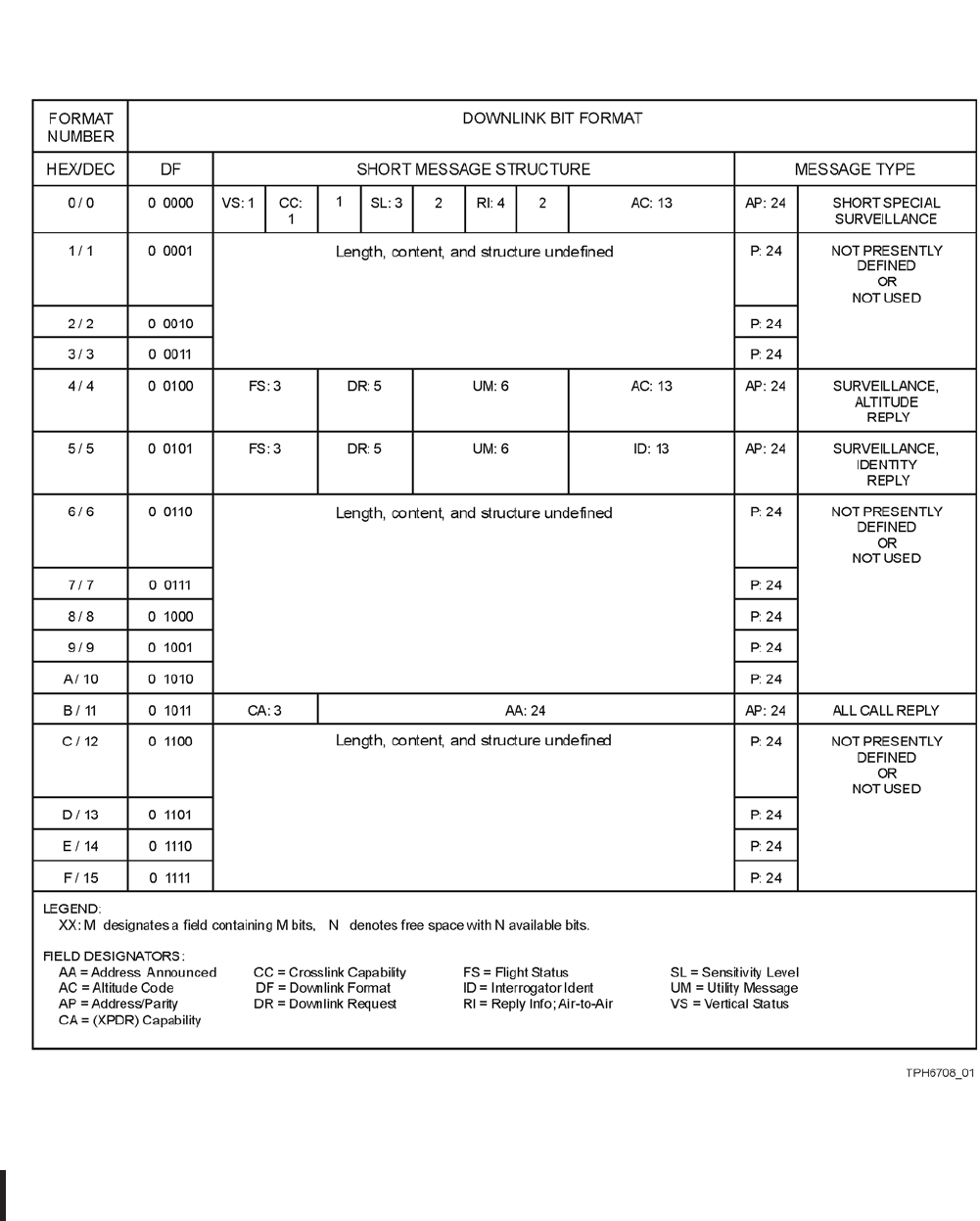
ROCKWELL COLLINS
COMPONENT MAINTENANCE MANUAL with IPL
TDR-94, PART NO 622-9352
Mode S, Reply Code Summary
Figure 14 (Sheet 1 of 2)/GRAPHIC 34-50-96-99B-081-A01
34-50-96 Page 55
May 18/06
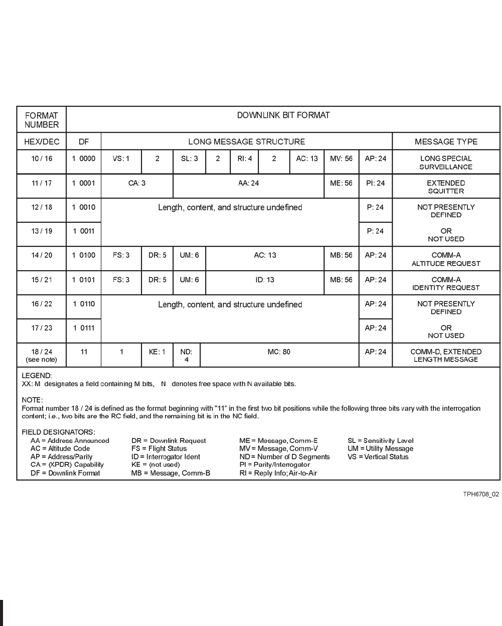
ROCKWELL COLLINS
COMPONENT MAINTENANCE MANUAL with IPL
TDR-94, PART NO 622-9352
Mode S, Reply Code Summary
Figure 14 (Sheet 2 of 2)/GRAPHIC 34-50-96-99B-081-A01
34-50-96 Page 56
May 18/06

ROCKWELL COLLINS
COMPONENT MAINTENANCE MANUAL with IPL
TDR-94, PART NO 622-9352
SUBTASK 34-50-96-870-005-A01
E. Typical TDR 94/94D ATC/Mode S Transponder Installations
(1) Introduction
(a) This paragraph gives you an overview of the TDR 94/94D operating environment.
For installation detail, refer to the TDR 94/94D ATC/Mode S Transponder,
Installation Manual which is contained in the Collins Pro Line II Comm/Nav/Pulse
System Installation Manual, CPN 523-0772719.
(b) The TDR 94/94D ATC/Mode S Transponder offers a wide range of installation
options. First you should recognize the difference between the TDR 94 and the
TDR 94D; the TDR 94 is for single antenna installations, while the TDR 94D can
operate with single or dual antenna installations. You are likely to find the TDR 94D
in most TCAS installations because dual antennas are required in TCAS.
(c) Both transponders can accept control data in CSDB or ARINC 429 format; this is
set at installation by means of special external straps and is determined by the type
of control being used.
(d) The following paragraphs and accompanying diagrams describe various installation
configurations. The first diagram, Figure 15/GRAPHIC 34-50-96-99B-082-A01,
shows the various strapping options that must be considered for all installations.
These strapping options are applicable to all installations even though they are
not shown on the other block diagrams.
34-50-96 Page 57
May 18/06
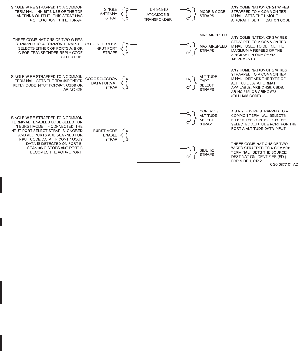
ROCKWELL COLLINS
COMPONENT MAINTENANCE MANUAL with IPL
TDR-94, PART NO 622-9352
TDR-94/94D ATC Mode S Transponder Strapping Options
Figure 15/GRAPHIC 34-50-96-99B-082-A01
(2) TDR-94 with CSDB Code Selection
(a) Figure 16/GRAPHIC 34-50-96-99B-083-A01 shows a TDR 94 installation with a
CTL 92/92A CSDB transponder control unit and an altitude encoder. This type
of encoder typically supplies altitude data in Gillham code (ARINC 572) format.
The encoder data can be supplied to the CTL 92/92A or directly to the TDR 94.
However, because the encoder is likely to be located in the radio rack, with or near
the transponder, most installations will have the encoder connected directly to the
transponder to keep the wire run short.
(b) Figure 17/GRAPHIC 34-50-96-99B-084-A01 shows an installation using a Central
Air Data Computer (CADC) for altitude data which is similar to Figure 16/GRAPHIC
34-50-96-99B-083-A01. In each of these cases, external strapping is required
according to the type of altitude data being used.
(c) An alternate installation configuration is possible using ARINC 429 code selection.
In this case, an ARINC 429 source, such as an FMS, would be shown in place
of the CTL 92/92A with appropriate strapping as shown of Figure 15/GRAPHIC
34-50-96-99B-082-A01.
34-50-96 Page 58
May 18/06
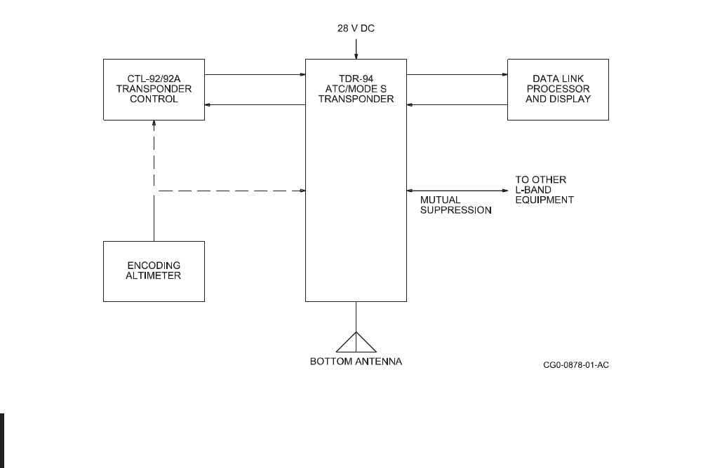
ROCKWELL COLLINS
COMPONENT MAINTENANCE MANUAL with IPL
TDR-94, PART NO 622-9352
(d) In TCAS installations using Gillham code encoders, two independent encoders
are required for monitoring redundancy and integrity. In this case, one encoder is
connected to the transponder, while the other supplies data to the CTL-92/92A. In
the control the altitude data is converted to CSDB data which is supplied to the
CTL-92T. The CSDB data is converted here to ARINC 429 and supplied to the
transponder. In the transponder the altitude from the directly-connected encoder is
compared to the ARINC 429 data from the other encoder. If the two altitude sources
do no agree within 500 feet, a diagnostic code is generated.
TDR-94 ATC/Mode S Transponder, with CTL-92/92A Transponder Control
Unit, Typical Installation Diagram
Figure 16/GRAPHIC 34-50-96-99B-083-A01
34-50-96 Page 59
May 18/06
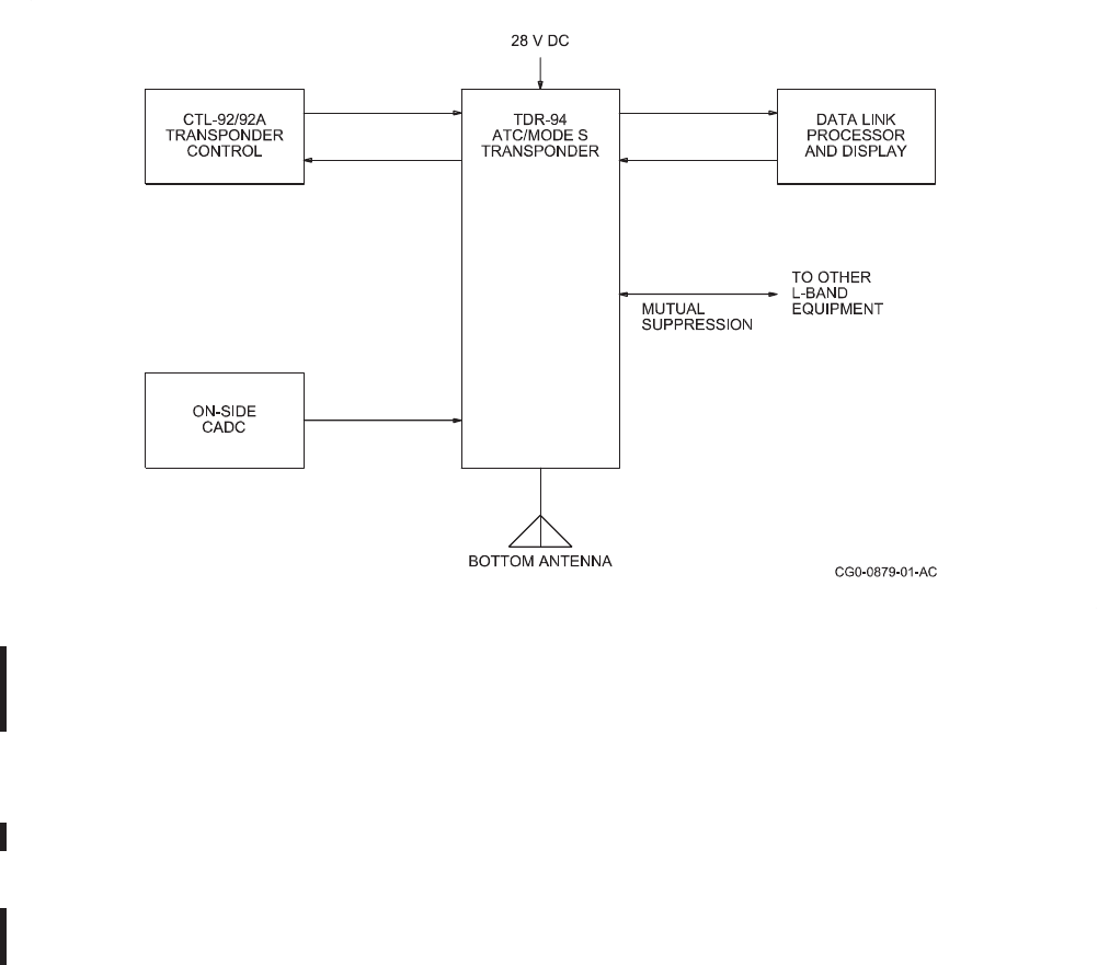
ROCKWELL COLLINS
COMPONENT MAINTENANCE MANUAL with IPL
TDR-94, PART NO 622-9352
TDR-94 ATC/Mode S Transponder, With CTL-92/92A Transponder Control and CADC
Altitude Source, Typical Installation Diagram
Figure 17/GRAPHIC 34-50-96-99B-084-A01
(3) TDR-94D with CSDB Code Selection and Dual Antenna Operation
(a) Figure 18/GRAPHIC 34-50-96-99B-085-A01 shows a TDR 94D in a TCAS
installation with a CSDB control and dual antennas. If the transponder is operated
with only a single antenna, a special strap is required. The diagram also shows a
CADC for altitude data. This can be an encoder as shown in Figure 16/GRAPHIC
34-50-96-99B-083-A01. Either way, appropriate strapping is required. The
CTL-92T, a requirement for TCAS control, is connected between the TDR-94D and
the CTL-92/92A. In this installation, transponder control data is entered on the
CTL-92/92A, and the TCAS control data is added to the data word in the CTL-92T.
34-50-96 Page 60
May 18/06
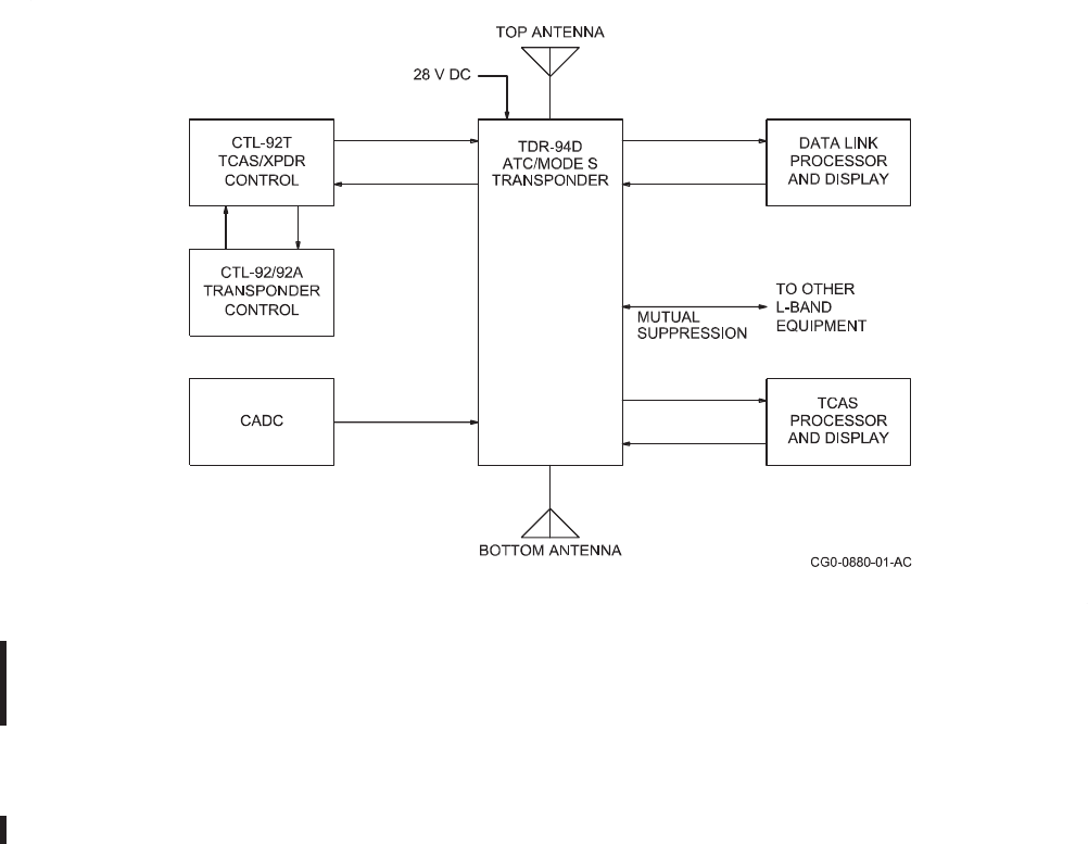
ROCKWELL COLLINS
COMPONENT MAINTENANCE MANUAL with IPL
TDR-94, PART NO 622-9352
TDR-94D ATC/Mode S Transponder, Datalink and TCAS Installation, With CSDB Control
and CADC Altitude Data Source, Typical Installation Diagram
Figure 18/GRAPHIC 34-50-96-99B-085-A01
(4) TDR-94D/TCAS with ARINC 429 Code Selection and Dual Antenna
(a) Figure 19/GRAPHIC 34-50-96-99B-086-A01 shows a TDR 94D in a relatively
complex installation. This can be seen as a typical TCAS and data link installation
using an ARINC 429 source for code selection.
34-50-96 Page 61
May 18/06
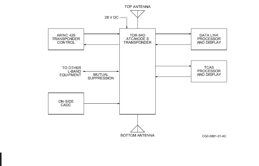
ROCKWELL COLLINS
COMPONENT MAINTENANCE MANUAL with IPL
TDR-94, PART NO 622-9352
TDR-94D ATC/Mode S Transponder, with ARINC 429 Tuning Source, Typical Installation Diagram
Figure 19/GRAPHIC 34-50-96-99B-086-A01
34-50-96 Page 62
May 18/06

ROCKWELL COLLINS
COMPONENT MAINTENANCE MANUAL with IPL
TDR-94, PART NO 622-9352
TASK 34-50-96-870-807-A01
7. Integrated Circuit Descriptions
A. The TDR-94/94D uses numerous types of integrated circuits. Always refer to the Illustrated
Parts List (IPL) when replacement parts are necessary. Table 8/Table 34-50-96-99A-039-A01
shows the different types of integrated circuits that the TDR-94/94D uses. Refer to the
manufacturer's data manuals (or WEB sites) if special data is necessary.
IC TYPE DESCRIPTION
Refer to Figure
20/GRAPHIC 34-
50-96-99B-087-A01
Basic Logic Gate Descriptions
Refer to Figure
21/GRAPHIC 34-
50-96-99B-088-A01
Basic Operational Amplifier Descriptions
02 +5V Precision Voltage Reference/Temperature Transducer
117 Adjustable 3-Terminal Positive Voltage Regulator (1.2 to 37V)
1596 Balance Modulator Demodulator Microcircuit
1825 High Speed Pulse Width Modulator Regulator
10135 2X J-K Master/Slave Flip Flop
12093 Low Power Prescaler
2222A 4X 2222A Transistor Package
22V10C Programmed PAL
26LS32 4X Differential Line Receiver
28HC256 32k x 8-Bit EEPROM
29F010 128k x 8-Bit Flash Memory
3127 High Frequency Low Current Transmitter Array
317L Adjustable Positive Voltage Regulator
31015 ARINC 429 Receiver/Transmitter ASIC
580 Voltage Reference
7C109 128k x 8-Bit Static RAM
7C291L Programmed 2k x 8-Bit UV EPROM
7C291L Programmed 2k x 8-Bit UV EPROM
7130 1k x 8-Bit Dual Port Static RAM
Integrated Circuit Descriptions Cont.
Table 8/Table 34-50-96-99A-039-A01
34-50-96 Page 63
May 18/06

ROCKWELL COLLINS
COMPONENT MAINTENANCE MANUAL with IPL
TDR-94, PART NO 622-9352
IC TYPE DESCRIPTION
74AHC1G04 Inverting Buffer
74HC259 8-Bit Addressable Latch/1 of 8 Decoder
74HC373 Octal 3-State Inverting D-Type Transparent Latch
74HC74 Dual D-Type Flip Flop with Set and Reset
74HCT244 Octal 3- State Buffer
74AC245 Octal Bus Transceiver, 3-State Non-Inverting
74AC374 OctalD-TypeFlipFlopwith3-StateOutputs
74HCT74 Dual D-Type Flip Flop
7800-10B Pulse Decoder Gate Array
80C196KC 16-Bit Microcontroller
831-7172-001 Programmed FPGA
835-1681-030 Memory Decode and Mux Logic Microcircuit
9638 Dual Differential Line Driver
9665-052 Message Processor Gate Array
AD580TH Low Drift Voltage Reference
AS214-92 0.1-3 GHz SPDT Switch
ATtiny 13 Programmed 8-Bit Microcontroller
ERA-2SM RF/MMIC Surface Mount Amplifier
ERA-5SM RF/MMIC Surface Mount Amplifier
JMS-5LH Double Balance RF Mixer (Surface Mount Package)
LM235 Temperature Sensor
LM317M Adjustable Positive Voltage Regulator
LMX2326TM Frequency Synthesis Phase-Lock Loop Microcircuit
M27C256B-70C6 Programmed 32k x 8-Bit UV EPROM
MAX2606EUT-T Voltage-Controlled Oscillator Microcircuit
MAX693A Microprocessor Supervisory Circuit
MB1501 Serial Input Phase-Lock Loop Frequency Synthesizer
MC149680 Modulator/Demodulator Microcircuit
MC74HC4316AD Quad Switch Microcircuit
MMPQ2907 Quad General Purpose PNP Transistor Package
Integrated Circuit Descriptions Cont.
Table 8/Table 34-50-96-99A-039-A01
34-50-96 Page 64
May 18/06

ROCKWELL COLLINS
COMPONENT MAINTENANCE MANUAL with IPL
TDR-94, PART NO 622-9352
IC TYPE DESCRIPTION
MSA-0686 RF/MMIC Amplifier Microcircuit
MSA-386 RF/MMIC Amplifier Microcircuit
RF MIXER Double Balance RF Mixer (Surface Mount Package)
RMS-5 Double Balance RF Mixer (Surface Mount Package)
SGA-4586 Cascadeable 50-Ohm Amplifier
SL1451 Wide-Band Phase Lock Loop FM Detector
SN74BNT2244ADB Octal Buffer and Line/MOS Drivers with 3-State Outputs
UPC1663GV Ultra Wide-Band Amplifier
UPC2712TB MMIC Wide-Band Amplifier
Integrated Circuit Descriptions
Table 8/Table 34-50-96-99A-039-A01
34-50-96 Page 65
May 18/06
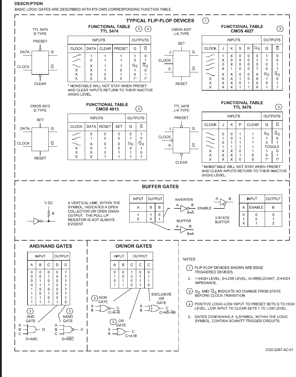
ROCKWELL COLLINS
COMPONENT MAINTENANCE MANUAL with IPL
TDR-94, PART NO 622-9352
Basis Logic Gate Descriptions
Figure 20/GRAPHIC 34-50-96-99B-087-A01
34-50-96 Page 66
May 18/06
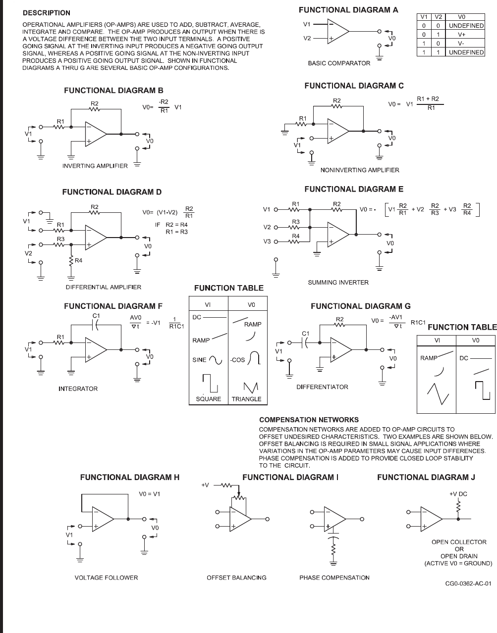
ROCKWELL COLLINS
COMPONENT MAINTENANCE MANUAL with IPL
TDR-94, PART NO 622-9352
Basis Operational Amplifier Descriptions
Figure 21/GRAPHIC 34-50-96-99B-088-A01
34-50-96 Page 67/68
May 18/06

ROCKWELL COLLINS
COMPONENT MAINTENANCE MANUAL with IPL
TDR-94, PART NO 622-9352
TESTING AND FAULT ISOLATION
TASK 34-50-96-700-801-A01
1. Introduction
A. Performance (customer acceptance) test procedures, calibration procedures, and
schematics for the -004, -005, -006, -007, -008, -108, -308, -309, -408, and -409 statuses of
the TDR-94/94D Mode S Transponder are provided in this section.
TASK 34-50-96-700-802-A01
2. T
est Equipment
A. Refer to the Special Tools, Fixtures, and Equipment section for information on the test
equipment required.
TASK 34-50-96-700-803-A01
3. T
est Procedures
SUBTASK 34-50-96-700-001-A01
A. Use of Test Procedures
NOTE: Testing is restricted to only authorized Rockwell Collins service centers.
(1) Use Table 1001/Table 34-50-96-99A-009-A01, Final Performance (Customer
Acceptance) Test to determine if the TDR-94/94D is operating properly. Use the
alignment procedures in Table 1002/Table 34-50-96-99A-010-A01 to calibrate the
TDR-94/94D.
SUBTASK 34-50-96-700-002-A01
B. Final Performance (Customer Acceptance) Test
(1) The Final Performance (Customer Acceptance) Test, Table 1001/Table
34-50-96-99A-009-A01, is performed with the cover on the unit and provides a relatively
high degree of assurance that the TDR-94/94D is properly operating. The final
performance test is essentially a return-to-service test. The final performance test
can also be used as a customer acceptance or receiving inspection test. After any
repairs, all final performance test steps must be successfully completed with the cover
installed before returning a unit to service. The final performance test can also be used
to isolate a fault to a functional area, thus determining which alignment procedures
may be applicable. Some of the performance criteria have been adjusted to allow for
the tolerances of typical test equipment.
SUBTASK 34-50-96-700-003-A01
C. Detailed Performance Test
(1) The detailed performance test is combined with the final performance test in Table
1001/Table 34-50-96-99A-009-A01.
34-50-96 Page 1001
Jun 20/08

ROCKWELL COLLINS
COMPONENT MAINTENANCE MANUAL with IPL
TDR-94, PART NO 622-9352
SUBTASK 34-50-96-700-004-A01
D. Alignment Procedures
(1) Refer to Table 1002/Table 34-50-96-99A-010-A01 for the alignment procedures for
the TDR-94/94D. If the final performance (customer acceptance) test successfully
completes, no alignment procedures are required.
TASK 34-50-96-810-801-A01
4. Fault Isolation
SUBTASK 34-50-96-810-001-A01
A. Fault Isolation Philosophy
CAUTION: REFER TO ADVISORIES PARAGRAPH IN THE INTRODUCTION FOR
ESDS HANDLING CAUTION AND COMPONENT WARNING.
(1) This section provides the primary information that repair personnel should use to isolate
faults in the TDR 94/94D. All sections of this manual have important data to aid in the
total repair and understanding of the unit. These sections are referenced, as necessary,
to facilitate completion of the repair tasks.
(2) Defective avionics equipment will usually fall into one of two categories: failure with a
specific complaint and failures with an unspecified complaints. The function of this
section is to guide fault isolation, first to a specific malfunction, then to the applicable
circuit area. Voltages and waveforms, in addition to the theory of operation help the
technician to isolate the faulty parts.
(3) Fault isolation and troubleshooting are performed using the test equipment listed in the
Special Tools, Fixtures, Equipment and Consumables section of this manual.
SUBTASK 34-50-96-810-002-A01
B. Troubleshooting Approach
(1) Unspecified Complaint
(a) Troubleshooting a unit with an unspecified complaint requires the technician to test
the unit according to the performance test to determine if a fault actually exists. In
cases where the unit passes all portions of the test and no fault is discovered, the
unit can be returned to the aircraft as good and reinstalled. However, an actual fault
may still persist and all associated equipment and aircraft wiring should be checked.
(b) When a unit does fail the performance test, the next objective is to isolate the actual
fault or faults, and begin in-depth troubleshooting procedures. Begin by performing
the specific fault isolation procedure(s) in this section.
34-50-96 Page 1002
May 18/06

ROCKWELL COLLINS
COMPONENT MAINTENANCE MANUAL with IPL
TDR-94, PART NO 622-9352
(2) Specified Complaint
(a) Maintenance tags that indicate specific complaints help expedite the troubleshooting
process. The technician may, in many cases, choose to omit the performance test
and proceed directly to the any applicable fault isolation procedure.
SUBTASK 34-50-96-810-003-A01
C. Troubleshooting Aids
(1) Maintenance Aid Diagrams - Maintenance aid diagrams are provided in the Schematics
and Wiring Diagrams section of this manual, facing the schematic diagrams, to aid in
component location and identification/location of test points. Waveforms (if applicable)
are shown at troubleshooting test points.
(2) Maintenance Aid and Schematic Change Pages - Maintenance Aid and Schematic
Change Pages are included in the Schematic and Wiring Diagrams section of this
manual to provide information on schematic changes necessitated by production
changes of service bulletin modifications.
(3) Schematic Diagrams - Schematic diagrams are provided in the Schematic and Wiring
Diagrams section of this manual as an aid to signal tracing and fault isolation.
(4) Fault Isolation and Diagnostic Procedures - Digital circuit card troubleshooting will be
accomplished using standard digital troubleshooting techniques with standard test
equipment.
34-50-96 Page 1003/1004
May 18/06
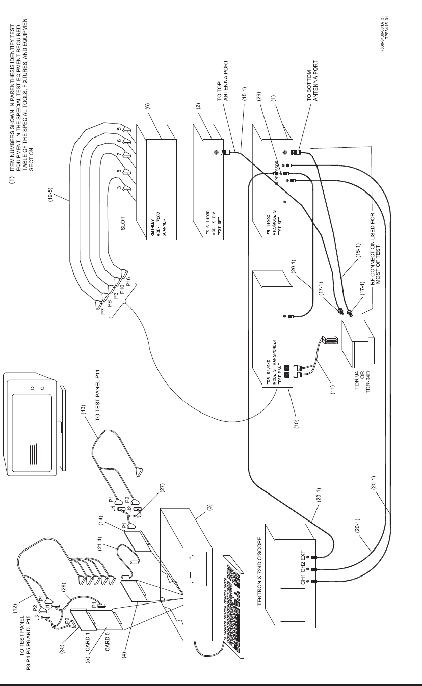
ROCKWELL COLLINS
COMPONENT MAINTENANCE MANUAL with IPL
TDR-94, PART NO 622-9352
TDR-94/94D Test Setup Diagram (Preferred Method)
Figure 1001/GRAPHIC 34-50-96-99B-020-A01
34-50-96 Page 1005/1006
May 18/06
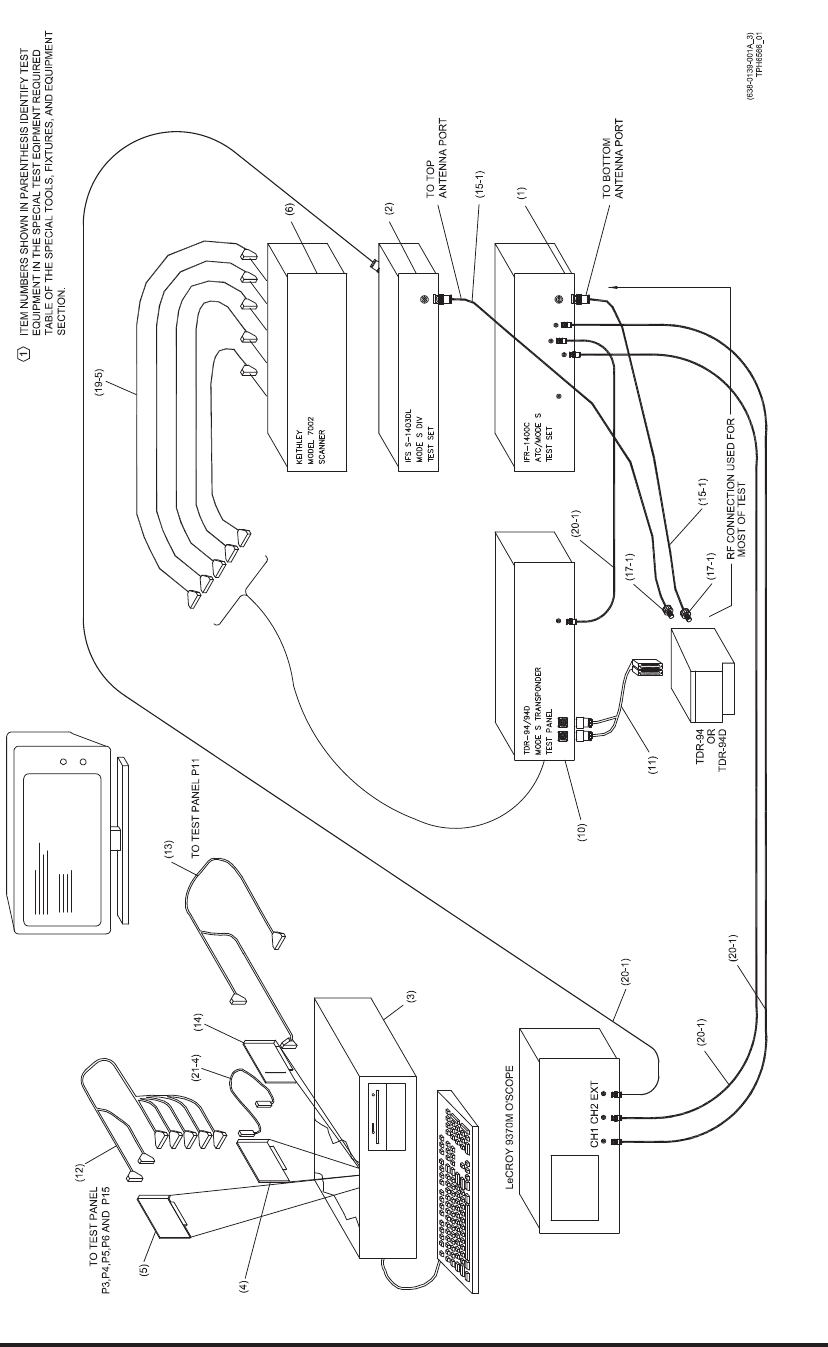
ROCKWELL COLLINS
COMPONENT MAINTENANCE MANUAL with IPL
TDR-94, PART NO 622-9352
TDR-94/94D Test Setup Diagram (Alternate Method)
Figure 1002/GRAPHIC 34-50-96-99B-036-A01
34-50-96 Page 1007/1008
May 18/06

ROCKWELL COLLINS
COMPONENT MAINTENANCE MANUAL with IPL
TDR-94, PART NO 622-9352
TASK 34-50-96-810-802-A01
5. Procedures
SUBTASK 34-50-96-810-004-A01
A. TDR-94/94D Final Performance (Customer Acceptance) Test Procedure
STEP PROCEDURE DESIRED RESULTS
0.0 SETUP INSTRUCTIONS
0.1 Preferred Setup: Connect TDR-94/94D as shown in Figure
1001/GRAPHIC 34-50-96-99B-020-A01. Test equipment
item numbers (XX) that appear in the illustration identify
test equipment in Table 9002/Table 34-50-96-99A-032-A01
of the Special Tools, Fixtures, and Equipment section.
Alternate Setup: Connect TDR-94/94D as shown in Figure
1002/GRAPHIC 34-50-96-99B-036-A01. Test equipment
item numbers (XX) that appear in the illustration identify test
equipment in the Special Tools, Fixtures, and Equipment
section Table 9003/Table 34-50-96-99A-042-A01.
NOTE: Interrogation power levels and transmitter output
power are referenced to the rear connector(s)
of the unit under test (UUT). The insertion loss
of coaxial cables between the UUT and the test
equipment must be accounted for.
Final Performance (Customer Acceptance) Test. Cont.
Table 1001/Table 34-50-96-99A-009-A01
34-50-96 Page 1009
May 18/06

ROCKWELL COLLINS
COMPONENT MAINTENANCE MANUAL with IPL
TDR-94, PART NO 622-9352
STEP PROCEDURE DESIRED RESULTS
0.2 AUTOMATIC TEST EQUIPMENT (FINAL) TESTS
Preferred Setup: The TDR-94 and TDR-94D are
“semi-automatically” tested on a station configured per Figure
1001/GRAPHIC 34-50-96-99B-020-A01 and Table 9002/Table
34-50-96-99A-032-A01. Test software is listed in Table
9002/Table 34-50-96-99A-032-A01. Insert Disk 1 and run
SETUP procedure.
Alternate Setup: The TDR-94 and TDR-94D are
"semi-automatically" tested on a station configured per Figure
1002/GRAPHIC 34-50-96-99B-036-A01and Table 9003/Table
34-50-96-99A-042-A01. Test software is listed in Table
9003/Table 34-50-96-99A-042-A01. Insert Disk 1 and run
SETUP procedure.
NOTE: Software is written/used by the factory, and may
contain specifications which are actually tighter than
required per the performance test requirements
(ptr). Therefore, refer to this test document for test
specifications for those automatic tests which fail.
0.3 IFR S-1403DL SETUP INFORMATION
The IFR S-1403DL test set must have C-Menu setup information
stored into memory for proper operation. Ensure that all
S-Menus (including S-Menu 00) are turned off. Set the following
C-Menu configuration and save it to store locations 1 and 2.
C-10 "f01 ATC" ANT B "off"
C-50 Counts "10s"
C-71 Trig Source "Selfinterr"
C-72 All On, Cal
C-73 All On
C-74 All On
C-75 ANT A mod source: "Int", ANT A Enable: "On"
C-76 S menu Radix: Octal
0.4 TEST CONDITIONS
Final data is to be taken after a 30 minute warm-up with
primary power applied. Perform the setup instructions in Table
1002/Table 34-50-96-99A-010-A01 for standard switch settings
prior to running an automatic test.
Final Performance (Customer Acceptance) Test. Cont.
Table 1001/Table 34-50-96-99A-009-A01
34-50-96 Page 1010
May 18/06

ROCKWELL COLLINS
COMPONENT MAINTENANCE MANUAL with IPL
TDR-94, PART NO 622-9352
STEP PROCEDURE DESIRED RESULTS
0.5 BUS NAMING CONVENTIONS
When reading this test procedure, the terms CSDB and PLII
are used interchangeably to denote the Commercial Standard
Digital Bus, commonly known as the Pro-Line II bus at Rockwell
Collins, Inc.
The ARINC 429 data bus is commonly called the ARINC bus or
the 429 bus and either term may appear in documentation.
Selection of busses from the test software will refer to port "A"
as port 0, port "B" as port 1, and port "C" as port 2.
1.0 RECEIVER TESTS
Perform the following tests on both the top and bottom antenna
ports for the TDR-94D. For the TDR-94, perform only those
tests specified for the bottom channel.
1.1 MTL Test
Test MTL is defined as the minimum interrogation power level
which produces a reply rate of at least 90%.
Determine the minimum interrogation level (MTL) required to
obtain at least a 90% reply rate for the following interrogations.
Verify that these levels are between -75 and -79 dBm.
Interrogations
A. MODE-S only All-Call
B. ATCRBS MODE-A/MODE-S All-Call
C. ATCRBS MODE-C
NOTE: If the MTL cannot be established within the specification
limits, A7R127 and/or A7R137 (CPN 833-6008-020)
may be added as required to adjust temperature
compensation. Refer to the A7 maintenance aid
diagram for component location. This information is
provided for reference only, after initial values are
determined in production, no further temperature
compensation adjustments should be necessary.
TOP BOTTOM
_____ _____
_____ _____
_____ _____
NOTE: Refertostep22.0in
Table 1002/Table 34-
50-96-99A-010-A01,
Alignment Procedure.
1.2 Sensitivity Variation with Frequency Test
Using ATCRBS MODE-C interrogations, ensure that MTL does
not vary by more than ±1 dB for interrogation frequencies
between 1029.8 and 1030.2 MHz.
TOP BOT
1029.8 MHz ____ ____
1030.2 MHz ____ ____
Final Performance (Customer Acceptance) Test. Cont.
Table 1001/Table 34-50-96-99A-009-A01
34-50-96 Page 1011
May 18/06

ROCKWELL COLLINS
COMPONENT MAINTENANCE MANUAL with IPL
TDR-94, PART NO 622-9352
STEP PROCEDURE DESIRED RESULTS
1.3 Receiver Bandwidth Test
Vary the interrogation RF frequency to 1007, 1053, 1060, and
1150 MHz. Verify the MODE-A interrogation level, required to
produce 90% reply efficiency is greater than -17 dBm.
TOP BOT
1007 MHz ____ ____
1053 MHz ____ ____
1060 MHz ____ ____
1150 MHz ____ ____
1.4 Dynamic Range Test
Verify a minimum reply rate of at least 90% for the following
interrogations at input signal levels of -73 dBm and -19 dBm.
Interrogations
A. MODE-S only All-Call
B. ATCRBS MODE-A/MODE-S All-Call
C. ATCRBS MODE-C
Signal level (dBm)
-73dBm -19dBm
TOPBOT TOPBOT
___ ___ ___ ___
___ ___ ___ ___
___ ___ ___ ___
1.5 Sensitivity Limit Test
For the following interrogations at a -81 dBm input signal level,
verify that the reply rate does not exceed 10%.
Interrogations
A. MODE-S only All-Call
B. ATCRBS MODE-A/MODE-S All-Call
C. ATCRBS MODE-C
TOP BOTTOM
_____ _____
_____ _____
_____ _____
1.6 Undesired Replies
For this test, squitter must be disabled by setting Self-Test Inhibit
discrete input, P2-38 (-004 thru -007) or P1-19 (-008, -108,
-308, -309, -408, -409) to ground. Turn off all interrogations.
Verify that the ATCRBS random replies are less than 5 per
second and the MODE-S replies are less than 1 per 10
seconds, averaged over a period of at least 30 seconds.
After this test, turn interrogations back on and remove the
ground from P2-38 or P1-19.
TOP BOT
ATCRBS ____ ____
MODE-S ____ ____
2.0 TRANSMITTER REQUIREMENTS
Unless otherwise specified, perform the following tests on both
the top and bottom antenna ports using a MODE-S test set. For
the TDR-94, you must do only the tests for the bottom antenna
port.
2.1 Transmitter Frequency Test
Ensure that the output transmitter frequency is 1090 ±0.5 MHz. _____ MHz
Final Performance (Customer Acceptance) Test. Cont.
Table 1001/Table 34-50-96-99A-009-A01
34-50-96 Page 1012
Jun 20/08

ROCKWELL COLLINS
COMPONENT MAINTENANCE MANUAL with IPL
TDR-94, PART NO 622-9352
STEP PROCEDURE DESIRED RESULTS
2.2 Transmitter Power Test
a. Interrogate ATCRBS interrogations at a rate of 450 per
second, or MODE-S interrogations at a rate of 50 per
second. Verify that the output transmitter power is between
315 and 500 watts measured at the strongest reply pulse.
Verify that the weakest pulse is within 1 dB of the strongest
for ATCRBS replies and within 2 dB for MODE-S replies.
Verify the weakest pulse exceeds 250 watts.
Strongest ATCRBS pulse Spec: 315 to 500 watts
Weakest ATCRBS pulse Spec: = strongest ±1 dB
Weakest MODE-S pulse Spec: = strongest ±2 dB
TOP BOTTOM
_____ _____
_____ _____
_____ _____
NOTE: Record the peak level of the strongest pulse in dBm to
use as a reference for measurements made in step 2.3.
CAUTION: BEFORE PERFORMING STEP B, SEPARATE
THE TRANSMITTER MODULE FROM THE MAIN
CHASSIS AND DISCONNECT HIGH VOLTAGE
FROM THE TRANSMITTER. FAILURE TO DO
THIS WILL RESULT IN SEVERE DAMAGE TO
THE SPECTRUM ANALYZER. ALL COVERS
MUST REMAIN INTACT FOR DATA TO BE VALID.
b. Connect the transmitter output directly to the spectrum
analyzer. Ensure that the 1090 MHz L.O. leakage from the
antenna port is less than -70 dBm when not transmitting.
Reconnect high voltage to the transmitter and reassemble
the transmitter module to the main chassis after completing
the test.
1090 MHz L.O. leakage Spec: less than -70 dBm
TOP BOTTOM
_____ _____
Final Performance (Customer Acceptance) Test. Cont.
Table 1001/Table 34-50-96-99A-009-A01
34-50-96 Page 1013
May 18/06

ROCKWELL COLLINS
COMPONENT MAINTENANCE MANUAL with IPL
TDR-94, PART NO 622-9352
STEP PROCEDURE DESIRED RESULTS
2.2
(Cont)
(This test applies to TDR-94D only.)
c. Set the self-test inhibit discrete to active to prevent
squittering. Ensure that the transmitter power output of the
nonselected antenna is attenuated at least 20 dB relative
to the selected antenna during the time the transmitter is
transmitting on the other antenna port. Set the self-test
inhibit discrete to disable after completing the test.
Nonselected antenna power Spec: MIN. 20 dB attenuation _____
2.3 Transmitter Spectrum and Reply Pulse Shape
Set up to transmit only MODE-S replies at 50/second. Observe
the output spectrum with a spectrum analyzer. Use a 100-kHz
resolution bandwidth or less. Use the peak level reference
recorded in step 2.2. for the measurements below. Verify the
spectrum does not exceed the following limits:
Frequency Difference
(MHz from Carrier) Spec:
>= 1.3 and <7 3
>= 7 and <23 20
>= 23 and <78 40
>= 78 60
Max Relative Response
(dB down from peak ref)
TOP BOTTOM
_____ _____
_____ _____
_____ _____
_____ _____
2.4 Reply Pulse Shape
For both ATCRBS and MODE-S replies, verify that the pulse
rise time is less than 100 ns and that the pulse decay time is
less than 200 ns.
ATCRBS
MODE-S
TOP BOTTOM
RISE FALL RISE FALL
____ ____ ____ ____
____ ____ ____ ____
If these results are not met,
select A3C216 test select
value from page 10150 (figure
6) to get results into specs.
2.5 Burst Tests
For these tests, verify correct replies and output power for all
interrogations.
2.5.1 ATCRBS Burst Tests
Verify that at least 120 ATCRBS 15-pulse replies can be
generated in 100 ms. Repeat the test at a once per second rate.
TOP BOTTOM
_____ _____ (x)
Final Performance (Customer Acceptance) Test. Cont.
Table 1001/Table 34-50-96-99A-009-A01
34-50-96 Page 1014
Mar 14/08

ROCKWELL COLLINS
COMPONENT MAINTENANCE MANUAL with IPL
TDR-94, PART NO 622-9352
STEP PROCEDURE DESIRED RESULTS
2.5.2 MODE-S Burst Tests
Verify the following MODE-S reply capabilities:
50 MODE-S replies in a 1-second interval including
at least 16 long replies.
TOP BOTTOM
_____ _____ (x)
18 MODE-S replies in a 100-ms interval including
at least 6 long replies. _____ _____ (x)
8 MODE-S replies in a 25-ms interval including at
least 4 long replies. _____ _____ (x)
4 MODE-S replies in a 1.6-ms interval including at
least 2 long replies.
_____ _____ (x)
2.6 MODE-A Reply Format, Ident Interval, and Reply Delay
Inject a normal MODE-A interrogation on the bottom channel
only. Select 7777 ident code on the test bench control head
simulator (computer). Verify IFR displays a 7777 code. Ensure
the downlink first framing pulse occurs 3.00 ±0.45 ˩safterthe
P3 leading edge of the interrogation input. Momentarily activate
the Ident switch and verify that the SPI pulse is present for 18
±2 seconds. Verify that the ATCRBS Downlink modulation has
pulse widths of 0.45 ±0.05 ˩s. Verify the following spacings
from the first framing pulse. All spacing and width tolerances
are ±50 ns. Repeat the reply delay test on the top channel
(TDR-94D only).
Downlink first framing pulse.
Spec: 3.00 ±0.45 ˩s after P3 input
TOP BOTTOM
_____ ws _____ ws
SPI pulse time
Spec: 18 ±2 seconds
BOTTOM
_____ s
ATCRBS Downlink pulse width
Spec: 0.45 ±0.05 ˩s
BOTTOM
_____ ws
Final Performance (Customer Acceptance) Test. Cont.
Table 1001/Table 34-50-96-99A-009-A01
34-50-96 Page 1015
May 18/06

ROCKWELL COLLINS
COMPONENT MAINTENANCE MANUAL with IPL
TDR-94, PART NO 622-9352
STEP PROCEDURE DESIRED RESULTS
2.6
(Cont)
Reply Pulse Position (˩s)
C1 1.45 ±50 ns
A1 2.90 ±50 ns
C2 4.35 ±50 ns
A2 5.80 ±50 ns
C4 7.25 ±50 ns
A4 8.70 ±50 ns
B1 11.60 ±50 ns
D1 13.05 ±50 ns
B2 14.50 ±50 ns
D2 15.95 ±50 ns
B4 17.40 ±50 ns
D4 18.85 ±50 ns
2ND framing pulse 20.30 ±50 ns
SPI 24.65 ±50 ns
BOTTOM
_______ (x)
_______ (x)
_______ (x)
_______ (x)
_______ (x)
_______ (x)
_______ (x)
_______ (x)
_______ (x)
_______ (x)
_______ (x)
_______ (x)
_______ (x)
_______ (x)
2.7 MODE-C Reply Format and Reply Delay
Interrogate with a normal MODE-C signal on the bottom
channel only. Select the Gillham discretes as the altitude
source by disconnecting rear connector P2 pins 41 and 42
from ground. Verify that F1 of the ATCRBS reply occurs 3.00
±0.45 ˩s after the interrogation P3 leading edge. Observe the
transmitted MODE-C reply. Verify that each of the Gillham ALT
bits will go low individually with a 39-k pull-down resistor. Use
the following table listed to locate the Gillham ALT bits. Repeat
the reply delay test on the top channel (TDR-94D only).
ATCRBSF1spacingfromP3
Spec: 3.00 ±0.45 ˩s
TOP BOTTOM
_____ ws _____ ws
Final Performance (Customer Acceptance) Test. Cont.
Table 1001/Table 34-50-96-99A-009-A01
34-50-96 Page 1016
May 18/06

ROCKWELL COLLINS
COMPONENT MAINTENANCE MANUAL with IPL
TDR-94, PART NO 622-9352
STEP PROCEDURE DESIRED RESULTS
2.7
(Cont)
LOCATION SIGNAL NAME
P1-1 Gillham ALT B4
P1-2 Gillham ALT B2
P1-3 Gillham ALT B1
P1-4 Gillham ALT A4
P1-5 Gillham ALT A2
P1-6 Gillham ALT A1
P1-7 Gillham ALT D4
P1-8 Gillham ALT D2
P1-9 Gillham ALT C4
P1-10 Gillham ALT C2
P1-11 Gillham ALT C1
F2 (2nd Framing Pulse)
Bit Reply Pulse
Toggles Spacing
(BOTTOM) from F1 (s)
_____ 17.40
_____ 14.50
_____ 11.60
_____ 8.70
_____ 5.80
_____ 2.90
_____ 18.85
_____ 15.95
_____ 7.25
_____ 4.35
_____ 1.45
_____ 20.30
3.0 DECODER TESTS
Unless otherwise specified, perform the following tests at -74
dBm and -20 dBm interrogation levels at each antenna port.
3.1 MODE-A P3 Deviation Negative, Max
Interrogate MODE-A with a P3 deviation of -0.9 sonthe
appropriate channel. Verify that the reply rate is NOT GREATER
than 10%.
Signal level (dBm)
-74 -20
BOT _____ _____
TOP _____ _____
3.2 MODE-A P3 Deviation Positive, Max
Interrogate MODE-A with a P3 deviation of +0.9 sonthe
appropriate channel. Verify that the reply rate is NOT GREATER
than 10%.
Signal level (dBm)
-74 -20
BOT _____ _____
TOP _____ _____
3.3 MODE-A Pulse Width, Narrow
Interrogate MODE-A with 0.30 s pulse width at a level of -45
dBm on the appropriate channel. Verify that the reply rate is
NOT GREATER than 10%.
Signal level (dBm)
-45
BOT _____
TOP _____
3.4 MODE-A Pulse Width, Normal
Interrogate MODE-A with 0.60 s pulse width on the
appropriate channel. Verify AT LEAST 90% MODE-A replies
are transmitted.
Signal level (dBm)
-74 -20
BOT _____ _____
TOP _____ _____
3.5 MODE-A P3 Deviation Negative, Min
Interrogate MODE-A with a P3 deviation of -0.30 sonthe
appropriate channel. Verify AT LEAST 90% MODE-A replies
are transmitted.
Signal level (dBm)
-74 -20
BOT _____ _____
TOP _____ _____
Final Performance (Customer Acceptance) Test. Cont.
Table 1001/Table 34-50-96-99A-009-A01
34-50-96 Page 1017
May 18/06

ROCKWELL COLLINS
COMPONENT MAINTENANCE MANUAL with IPL
TDR-94, PART NO 622-9352
STEP PROCEDURE DESIRED RESULTS
3.6 MODE-A P3 Deviation Positive, Min
Interrogate MODE-A with a P3 deviation of +0.30 sonthe
appropriate channel. Verify AT LEAST 90% MODE-A replies
are transmitted.
Signal level (dBm)
-74 -20
BOT _____ _____
TOP _____ _____
3.7 MODE-C P3 Deviation Negative, Max
Interrogate MODE-C with a P3 deviation of -0.90 sonthe
appropriate channel. Verify that the reply rate is NOT GREATER
than 10%.
Signal level (dBm)
-74 -20
BOT _____ _____
TOP _____ _____
3.8 MODE-C P3 Deviation Positive, Max
Interrogate MODE-C with a P3 deviation of +0.90 sonthe
appropriate channel. Verify that the reply rate is NOT GREATER
than 10%.
Signal level (dBm)
-74 -20
BOT _____ _____
TOP _____ _____
3.9 MODE-C P3 Deviation Negative, Min
Interrogate MODE-C with a P3 deviation of -0.30 sonthe
appropriate channel. Verify that the reply rate is AT LEAST 90%.
Signal level (dBm)
-74 -20
BOT _____ _____
TOP _____ _____
3.10 MODE-C P3 Deviation Positive, Min
Interrogate MODE-C with a P3 deviation of +0.30 sonthe
appropriate channel. Verify that the reply rate is AT LEAST 90%.
Signal level (dBm)
-74 -20
BOT _____ _____
TOP _____ _____
4.0 ATCRBS SLS TEST
Perform the following tests at MTL +3 dB or -74 dBm. Test also
at -60 dBm, -40 dBm, and -22 dBm input signal levels. Conduct
the following tests on the bottom antenna port for both TDR-94
and TDR-94D. Repeat the tests on the top antenna port of the
TDR-94D only.
4.1 MODE-C P2 at -1 dB
Interrogate with a MODE-C P1, P2, P3 triad with P2 at -1 dB.
DeviatetheP2position+0.2and-0.2s. Verify that the reply
rate is NOT GREATER than 10%.
Signal level (dBm)
-74 -60 -40 -22
BOT________
TOP ________
4.2 MODE-C P2 at -9 dB
Interrogate with a MODE-C P1, P2, P3 triad with P2 at -9 dB.
Verify that the reply rate is AT LEAST 90%.
Signal level (dBm)
-74 -60 -40 -22
BOT________
TOP ________
4.3 MODE-C P2 at 0 dB
Interrogate with a MODE-C P1, P2, P3 triad with P2 at 0 dB.
Set P2 pulse width to 0.60 s and verify that the reply rate is
NOT GREATER than 1%.
Signal level (dBm)
-74 -60 -40 -22
BOT________
TOP ________
Final Performance (Customer Acceptance) Test. Cont.
Table 1001/Table 34-50-96-99A-009-A01
34-50-96 Page 1018
May 18/06

ROCKWELL COLLINS
COMPONENT MAINTENANCE MANUAL with IPL
TDR-94, PART NO 622-9352
STEP PROCEDURE DESIRED RESULTS
4.4 MODE-A P2 at 0 dB
Interrogate with a MODE-A P1, P2, P3 triad with P2 at 0 dB.
Deviate the P2 position +0.65 sand-0.65s and verify that
the reply rate is AT LEAST 90%.
Signal level (dBm)
-74 -60 -40 -22
BOT________
TOP ________
4.5 SLS Suppression Interval
Interrogate with a P1, P2, ATCRBS suppression pair with P2
at 0 dB relative to P1. Follow with a normal MODE-A P1, P3
interrogation. Delay the second interrogation 26 sfromP2
of the first interrogation and verify that the reply rate is NOT
GREATER than 10%. Delay the second interrogation 44 s
from P2 of the first interrogation and verify that replies are
generated in response to the second interrogation at a rate of
AT LEAST 90%.
Second interrogation delayed 26 s. NOT GREATER than 10%
ATCRBS reply
________
Second interrogation delayed 44 s. AT LEAST 90% replies
to second interrogation
________
5.0 MODE-S SLS TEST
Perform the following tests at MTL +3 dB or -73 dBm and also at
-22 dBm interrogation input signal levels applied to the bottom
antenna port. Repeat the test for the top antenna port of the
TDR-94D only.
5.1 P5 Greater than P6
Ensure that a P5 pulse overlaying the SPR (Sync Phase
Reversal) of a MODE-S interrogation results in a reply rate of
NOT GREATER than 10% if its amplitude is greater than P6
by 3 dB.
Signal level (dBm)
-73 -22
BOT _____ _____
TOP _____ _____
5.2 P5 Less Than P6
Ensure that a P5 pulse overlaying the SPR of a MODE-S
interrogation results in greater than 99% replies if its amplitude
is less than P6 by 12 dB
Signal level (dBm)
-73 -22
BOT _____ _____
TOP _____ _____
6.0 ALL-CALL DECODER TEST
Perform the following tests at MTL +1 dB or -75 dBm and also
at -22 dBm interrogation input signal levels. Unless otherwise
specified, test the bottom antenna port for the TDR-94, and
both antenna ports for the TDR-94D.
Final Performance (Customer Acceptance) Test. Cont.
Table 1001/Table 34-50-96-99A-009-A01
34-50-96 Page 1019
May 18/06

ROCKWELL COLLINS
COMPONENT MAINTENANCE MANUAL with IPL
TDR-94, PART NO 622-9352
STEP PROCEDURE DESIRED RESULTS
6.1 P4 Pulse Width Variation, ATCRSB/MODE-S All-Call
a. Interrogate with a P1, P3, P4 ATCRBS/MODE-S ALL-CALL.
VarytheP4pulsewidthfrom1.45to1.75s. Ensure that
the downlink MODE-S reply rate exceeds 90%.
Signal level (dBm)
-75 -22
BOT _____ _____
TOP _____ _____
b. Ensure the downlink first preamble pulse occurs 128.00
±0.50 s after the P4 pulse leading edge.
Signal level (dBm)
-75 -22
BOT _____ _____
TOP _____ _____
c. Ensure that the downlink modulation has proper spacing and
widths for the preamble and information pulses. All spacing
and width tolerances are ±30 ns.
Signal level (dBm)
-75 -22
BOT _____ _____
TOP _____ _____
6.2 MODE-S Address
Ensure that the MODE-S address bits will go low individually
witha1.82-k pull-down resistor and remain high individually
witha18.2-k pull-down resistor. Use the following table to
locate and address the MODE-S address bits.
NOTE: TDR-94/94D transponders -004 status and later, read
and accept the MODE-S Address during power-on
initialization only. If the MODE-S Address is changed
after power-on initialization, the address will not
be accepted for use in replies to interrogations.
Consequently, if the MODE-S Address provided to
the UUT is changed, power to the UUT may have to
be cycled before proceeding with this test.
NOTE: If the resistor pull-down tests are performed at an
assembly level test, the top-level test may substitute
a short-to-ground, or open circuit, for 1.82 k and
18.2 k , respectively. Conduct this test for the bottom
antenna port only and at a convenient input signal level.
Final Performance (Customer Acceptance) Test. Cont.
Table 1001/Table 34-50-96-99A-009-A01
34-50-96 Page 1020
May 18/06

ROCKWELL COLLINS
COMPONENT MAINTENANCE MANUAL with IPL
TDR-94, PART NO 622-9352
STEP PROCEDURE DESIRED RESULTS
6.2
(Cont) SIGNAL NAME LOCATION
MODE-S ADDR B1 P1-33
MODE-S ADDR B2 P1-34
MODE-S ADDR B3 P1-35
MODE-S ADDR B4 P1-36
MODE-S ADDR B5 P1-37
MODE-S ADDR B6 P1-38
MODE-S ADDR B7 P1-39
MODE-S ADDR B8 P1-40
MODE-S ADDR B9 P1-41
MODE-S ADDR B10 P1-42
MODE-S ADDR B11 P1-43
MODE-S ADDR B12 P1-44
MODE-S ADDR B13 P1-45
MODE-S ADDR B14 P1-46
MODE-S ADDR B15 P1-47
MODE-S ADDR B16 P1-48
MODE-S ADDR B17 P1-49
MODE-S ADDR B18 P1-50
MODE-S ADDR B19 P1-51
MODE-S ADDR B20 P1-52
MODE-S ADDR B21 P1-53
MODE-S ADDR B22 P1-54
MODE-S ADDR B23 P1-55
MODE-S ADDR B24 P1-56
_____
_____
_____
_____
_____
_____
_____
_____
_____
_____
_____
_____
_____
_____
_____
_____
_____
_____
_____
_____
_____
_____
_____
_____
Final Performance (Customer Acceptance) Test. Cont.
Table 1001/Table 34-50-96-99A-009-A01
34-50-96 Page 1021
May 18/06

ROCKWELL COLLINS
COMPONENT MAINTENANCE MANUAL with IPL
TDR-94, PART NO 622-9352
STEP PROCEDURE DESIRED RESULTS
6.3 P4 Pulse Width Variation, ATCRBS-ONLY ALL
Interrogate with a P1, P3, P4 ATCRBS-Only All-Call. Vary the
P4 pulse width from 0.60 to 1.00 s. Verify that the reply rate
is NOT GREATER than 10%.
Signal level (dBm)
-75 -22
BOT _____ _____
TOP _____ _____
6.4 P4 Pulse Width Variation, ATCRBS/MODE-S ALL CALL
Interrogate with a P1, P3, P4 ATCRBS/MODE-S All-Call. Set
theP4pulsewidthto1.1and2.4s. Verify that the reply rate
is NOT GREATER than 10%.
Signal level (dBm)
-75 -22
BOT _____ _____
TOP _____ _____
6.5 P4 Minimum Pulse Width, ATCRBS-ONLY ALL CALL
Interrogate with a P1, P3, P4 ATCRBS-Only All-Call. Set P4
pulse width to 0.30 s. Verify that an ATCRBS reply occurs
within 3.00 ±0.50 s from P3, at a rate of AT LEAST 90%, and
the MODE-S reply rate is NOT GREATER than 10%.
10% or < MODE-S reply
90% or > ATCRBS reply
Signal level (dBm)
-75 -22
BOT _____ _____
TOP _____ _____
BOT _____ _____
TOP _____ _____
6.6 P4 Position Variation, ATCRBS/MODE-S ALL CALL
Interrogate with normal P1, P3, P4 ATCRBS/MODE-S All-Call
interrogations. Deviate the P4 position ±50 ns. Verify that the
All-Call replies are transmitted at a rate of AT LEAST 90%.
Signal level (dBm)
-75 -22
BOT _____ _____
TOP _____ _____
6.7 P4 Amplitude 6 dB Below P3
Interrogate with ATCRBS/MODE-S All-Call interrogations.
Adjust the P4 amplitude 6 dB below the amplitude of P3. Verify
that the MODE-S reply rate is NOT GREATER than 10% and
the ATCRBS rate is AT LEAST 90%.
10% or < MODE-S reply
90% or > ATCRBS reply
Signal level (dBm)
-75 -22
BOT _____ _____
TOP _____ _____
BOT _____ _____
TOP _____ _____
Final Performance (Customer Acceptance) Test. Cont.
Table 1001/Table 34-50-96-99A-009-A01
34-50-96 Page 1022
May 18/06

ROCKWELL COLLINS
COMPONENT MAINTENANCE MANUAL with IPL
TDR-94, PART NO 622-9352
STEP PROCEDURE DESIRED RESULTS
6.8 P4 Deviation, ATCRBS/MODE-S ALL CALL
Interrogate with ATCRBS/MODE-S All-Call interrogations.
DeviateP4±0.30s and verify that the ATCRBS reply rate is
AT LEAST 90% and the MODE-S reply rate is NOT GREATER
than 10%.
10% or < MODE-S reply
90% or > ATCRBS reply
Signal level (dBm)
-75 -22
BOT _____ _____
TOP _____ _____
BOT _____ _____
TOP _____ _____
6.9 P4 Amplitude 1 dB Below P3
Interrogate with ATCRBS-Only All-Call interrogation having a
signal level of -73 dBm. Adjust the P4 amplitude 1 dB below
amplitude of P3. Verify that the reply rate is NOT GREATER
than 10%.
Signal level (dBm)
-73
BOT _____
TOP _____
7.0 MODE-S DECODER TEST
Perform the following tests at MTL +1 dB or -75 dBm and also
-22 dBm interrogation levels. Test the bottom antenna port of
the TDR-94, and both antenna ports of the TDR-94D. Set the
ADLP select to active. If air/ground discrete is set to airborne,
cycle power before beginning tests.
Signal level (dBm)
-75 -22
BOT _____ _____
TOP _____ _____
7.1 MODE-S Reply Delay
Interrogate with Uplink Format UF=11 interrogations. Verify that
the first downlink preamble pulse occurs 128.00 ±0.25 s after
the SPR (Sync Phase Reversal) of the interrogation inputs.
Verify that the Downlink Response is DF=11.
7.2 SPR Deviation -Low
Interrogate with Uplink Format UF=11 interrogations. Deviate
the SPR position over +50 and -50 ns. Verify that the DF=11
downlink response rate is AT LEAST 90%.
+50 ns
-50 ns
Signal level (dBm)
-75 -22
BOT _____ _____
TOP _____ _____
BOT _____ _____
TOP _____ _____
Final Performance (Customer Acceptance) Test. Cont.
Table 1001/Table 34-50-96-99A-009-A01
34-50-96 Page 1023
May 18/06

ROCKWELL COLLINS
COMPONENT MAINTENANCE MANUAL with IPL
TDR-94, PART NO 622-9352
STEP PROCEDURE DESIRED RESULTS
7.3 SPR Deviation -High
Interrogate with Uplink Format UF=11 interrogations. Deviate
the SPR position to +200 ns and -200 ns. Verify that the DF=11
downlink response rate is NOT GREATER than 10%.
+200 ns
-200 ns
Signal level (dBm)
-75 -22
BOT _____ _____
TOP _____ _____
BOT _____ _____
TOP _____ _____
7.4 UF = 5/DF = 5
Interrogate with Uplink Format UF=5 interrogations. Verify that
the downlink response is DF=5. Conduct this test for bottom
antenna port only and at a convenient input signal level.
BOTTOM _____
7.5 UF = 5 Different Address
Interrogate with Uplink Format UF=5 interrogations that have
an address different than that of the unit under test. Verify no
reply occurs other than normal DF=11 squitter transmissions.
Conduct this test for the bottom antenna port only and at a
convenient input signal level.
BOTTOM _____
7.6 UF = 21/DF = 21
Interrogate with Uplink Format UF=21 interrogations. Verify that
the downlink response is DF=21. Conduct this test for bottom
antenna port only and at a convenient input signal level.
BOTTOM _____
7.7 UF = 0, Max Airspeed
Interrogate with Uplink Format UF=0 interrogations. Verify
that the MAX AIR SPEED bits independently toggle in the
downlink response of DF=0 when discrete pins P2-43, 44, 45
are switched. Conduct this test for bottom antenna port only
and at a convenient input signal level.
BOTTOM _____
7.8 UF = 11, Low-Level
Interrogate with Uplink Format UF=11 interrogations that have
an input signal level at MTL or -76 dBm. Trigger the scope
from the generator output of the IFR. Connect the transmitter
jack of the IFR to the vertical scope channel. Use the delayed
sweep function of the scope to view the first reply pulse with a
horizontal rate of 50 ns/div. Verify the jitter of the pulse does not
exceed 160 ns total (±80 ns.).
Signal level (dBm)
-76 -22
BOT _____ _____
TOP _____ _____
Final Performance (Customer Acceptance) Test. Cont.
Table 1001/Table 34-50-96-99A-009-A01
34-50-96 Page 1024
May 18/06

ROCKWELL COLLINS
COMPONENT MAINTENANCE MANUAL with IPL
TDR-94, PART NO 622-9352
STEP PROCEDURE DESIRED RESULTS
8.0 INTERFERENCE TEST
Perform the following tests for UF=11 MODE-S interrogations
at signal levels of -68 and -22 dBm. Inject an interference
pulse of 0.80 s duration, at a carrier frequency of 1030 MHz,
but incoherent with the interrogation signal. Test the bottom
antenna port for the TDR-94, and both antenna ports for the
TDR-94D.
NOTE: For steps 8.1 and 8.2, the interference pulse
can be coincident with a group of 3 or more
phase transitions spaced 0.25 s.
8.1 Interference Level 3 dB Less Than Signal Level
Verify that when the interference pulse overlays the MODE-S
interrogation anywhere after the Sync Phase Reversal, the reply
rate exceeds 50% if the interference amplitude is 3 dB less than
the interrogation signal level.
Signal level (dBm)
-68 -22
BOT _____ _____
TOP _____ _____
8.2 Interference Level 9 dB Less Than Signal Level
Verify that when the interference pulse overlays the MODE-S
interrogation anywhere after the MODE-S P1 pulse leading
edge, the reply rate is AT LEAST 90% if the interference
amplitude is 9 dB less than the interrogation signal level.
Signal level (dBm)
-68 -22
BOT _____ _____
TOP _____ _____
9.0 SQUITTER TEST
For this test, turn off the input interrogations.
9.1 Dual Antenna Squitter Rate
Ensure that squitter is generating a DF=11 (Acquisition Squitter)
reply at an average rate of 1.0 Hz, alternating between the top
and bottom antenna ports for the TDR-94D, and fixed on the
bottom antenna port for the TDR-94.
____ (check if okay)
9.2 Single Antenna Squitter Rate
Ensure that grounding the single antenna strap (by selecting
single antenna active on the test computer) prevents squitter
transmissions on the top antenna port, and that the bottom
antenna port alone continues to squitter at a 1.0-Hz rate.
NOTE: Unit input power must be cycled to recognize the
Single Antenna Strap discrete change.
____ (check if okay)
Final Performance (Customer Acceptance) Test. Cont.
Table 1001/Table 34-50-96-99A-009-A01
34-50-96 Page 1025
May 18/06

ROCKWELL COLLINS
COMPONENT MAINTENANCE MANUAL with IPL
TDR-94, PART NO 622-9352
STEP PROCEDURE DESIRED RESULTS
9.3 Airborne Position Extended Squitter (-004 through -007 and
-207 status TDR-94/94D)
a. Ensure that neither Air/Ground Discrete #1 or #2 (P2-53
or P1-27) are connected to ground (i.e., establishes the
airborne state).
b. Via the GPS/GNSS Input Data Bus, provide the transponder
with the appropriate labels and data indicated in Figure
1003/GRAPHIC 34-50-96-99B-021-A01. Each data
parameter shall be updated at least once per second.
c. Verify that the transponder properly transmits an
“Even_Second" DF=17 Extended Squitter transmission that
has the exact structure for the 'ME" field as shown in Figure
1003/GRAPHIC 34-50-96-99B-021-A01.
d. Verify that the transponder properly transmits the Airborne
Position Message at random intervals that are uniformly
distributed over the range from 0.4 to 0.6 second.
e. Verify that the transponder properly transmits the Airborne
Position alternately from the top and bottom antenna ports
for the TDR-94D and from the bottom antenna port only for
the TDR-94.
f. Verify the transponder continues to transmit DF=11
Acquisition Squitters while continuing to transmit the
Airborne Position Squitter Messages as specified in previous
steps c, d, and e.
g. Maintain the data inputs as provided in step b with
the exception that the UTC Time input should be
changed to read as indicated in Figure 1003/GRAPHIC
34-50-96-99B-021-A01.
h. Verify that the transponder properly transmits an
"Odd_Second" DF=17 Extended Squitter transmission that
has the exact structure for the "ME" field shown in Figure
1003/GRAPHIC 34-50-96-99B-021-A01.
Final Performance (Customer Acceptance) Test. Cont.
Table 1001/Table 34-50-96-99A-009-A01
34-50-96 Page 1026
Nov 10/06

ROCKWELL COLLINS
COMPONENT MAINTENANCE MANUAL with IPL
TDR-94, PART NO 622-9352
STEP PROCEDURE DESIRED RESULTS
9.3A GPS Bus/Airborne Position Extended Squitter/Time Tag
Verification (-108 status TDR-94/94D only)
a. Ensure that neither Air/Ground Discrete #1 or #2 (P2-53
or P1-27) are connected to ground (i.e., establishes the
airborne state).
b. Ensure that neither Configuration Select discrete 0 or 1
(P1-28 or P1-17) are connected to ground.
c. Ensure that ARINC 429 label 203 is not present on the
selected Altitude Input Bus.
d. Provide the transponder with a GPS Time Tag signal via the
GPS Time Tag input (P2-37 high, P2-38 low). The GPS
Time Tag signal is a differential (0-5 Vdc) 1 ms pulse that
repeats once per second.
e. Via the GPS/GNSS Input Data Bus, provide the transponder
with the appropriate labels and data indicated in Figure
1004/GRAPHIC 34-50-96-99B-022-A01. Each data
parameter must be updated at least one time each second.
f. Verify that the transponder properly transmits an
Even-Second DF=17 Extended Squitter transmission that
has the exact structure for the "ME" field indicated in Figure
1004/GRAPHIC 34-50-96-99B-022-A01.
g. Verify that the transponder properly transmits the Airborne
Position Message at random intervals that are uniformly
distributed over the range from 0.4 to 0.6 seconds.
h. Verify that the transponder properly transmits the Airborne
Position alternately from the top and bottom antenna ports
of the TDR-94D and from the bottom antenna port only of
the TDR-94.
i. Verify that the transponder continues to transmit DF=11
Acquisition Squitters while continuing to transmit the
Airborne Position Squitter messages indicated in steps f,
g, and h. above.
j. Verify that the transponder properly transmits an Odd-Second
DF=17 Extended Squitter transmission that has the
exact structure for the "ME" field indicated in Figure
1004/GRAPHIC 34-50-96-99B-022-A01.
Final Performance (Customer Acceptance) Test. Cont.
Table 1001/Table 34-50-96-99A-009-A01
34-50-96 Page 1027
May 18/06

ROCKWELL COLLINS
COMPONENT MAINTENANCE MANUAL with IPL
TDR-94, PART NO 622-9352
STEP PROCEDURE DESIRED RESULTS
9.3B GPS Bus/Airborne Position Extended Squitter/Time Tag
Verification (-008 status TDR-94/94D only)
a. Ensure that neither Air/Ground Discrete #1 or #2 (P2-53
or P1-27) are connected to ground (i.e., establishes the
airborne state).
b. Ensure that neither Configuration Select discrete 0 or 1
(P1-28 or P1-17) are connected to ground.
c. Ensure that ARINC 429 label 203 is not present on the
selected Altitude Input Bus.
d. Provide the transponder with a GPS Time Tag signal via the
GPS Time Tag input (P2-37 high, P2-38 low). The GPS
Time Tag signal is a differential (0-5 Vdc) 1 ms pulse that
repeats once per second.
e. Via the GPS/GNSS Input Data Bus, provide the transponder
with the appropriate labels and data indicated in Figure
1004/GRAPHIC 34-50-96-99B-022-A01 (for step e of test
9.3A). Each data parameter must be updated at least one
time each second.
f. Interrogate the transponder with the MODE-S interrogations
indicated in Figure 1005/GRAPHIC 34-50-96-99B-023-A01
to request BDS register 0.5.
g. Verify that the transponder responds properly with two DF=20
replies that have the exact structures for the "MB" field
indicated in Figure 1005/GRAPHIC 34-50-96-99B-023-A01.
h. Repeat step f. as necessary.
i. Verify that the transponder responds properly with two DF=20
replies that have the exact structures for the "MB" field
indicated in Figure 1005/GRAPHIC 34-50-96-99B-023-A01.
NOTE: Steps h. and i. may have to be repeated to get an
odd encoding since the transponder alternates the
encoding of latitude and longitude data on odd and
even intervals at rates of either 100 or 200 ms.
9.3C GPS Bus / Airborne Position Extended Squitter / Time Tag
Verification (-408/-409 )
Final Performance (Customer Acceptance) Test. Cont.
Table 1001/Table 34-50-96-99A-009-A01
34-50-96 Page 1028
Dec 16/09

ROCKWELL COLLINS
COMPONENT MAINTENANCE MANUAL with IPL
TDR-94, PART NO 622-9352
STEP PROCEDURE DESIRED RESULTS
a. Ensure that both Air/Ground Discrete #1 (P2-53) and
Air/Ground Discrete #2 (P1-27) are NOT connected to ground
(i.e., establish the airborne state).
b. Ensure that both Configuration Select “0” (P1-28) and
Configuration Select “1” (P1-17) are NOT connected to ground.
c. Ensure that there is no Arinc 429 Label 203 present on the
selected Altitude Input Bus.
d. Provide the transponder unit with a GPS Time Tag signal via
the GPS Time Tag inputs (P2-37 High, P2-38 Low). The GPS
time tag signal shall be a differential (0 –5 vdc) 1 millisecond
pulse, at a repetition rate of 1 per second.
e. Via the GPS/GNSS Input Data Bus, provide the transponder
with the appropriate labels and data indicated in Figure
1018/GRAPHIC 34-50-96-99B-089-A01. Each data parameter
shall be updated at least once per second.
f. Verify that the transponder properly transmits an
”Even-Second” DF=17 Extended Squitter transmission having
the exact structure for the ”ME” field indicated in Figure
1018/GRAPHIC 34-50-96-99B-089-A01.
NOTE: The single Antenna Bit (RF bit 40) will be set to a "0"
for the TDR-94D and a "1" for the TDR-94.
g. Verify that the transponder properly transmits the Airborne
Position Message at random intervals that are uniformly
distributed over the range from 0.4 to 0.6 seconds (i.e., 0.5
+/-0.1 seconds).
h. Verify that the transponder properly transmits the Airborne
Position alternately from the top and bottom antenna ports for
the TDR-94D and from the bottom antenna only for the TDR-94.
i. Verify that the transponder continues to transmit DF=11
Acquisition Squitters while continuing to transmit the Airborne
Position Squitter Messages as specified steps f, g, and h.
j. Verify that the transponder properly transmits an
”Odd-Second” DF=17 Extended Squitter transmission having
the exact structure for the ”ME” field indicated in Figure
1018/GRAPHIC 34-50-96-99B-089-A01.
9.3D GPS Bus / Airborne Position Extended Squitter / Time Tag
Verification (-308, -309 ONLY)
Final Performance (Customer Acceptance) Test. Cont.
Table 1001/Table 34-50-96-99A-009-A01
34-50-96 Page 1028.1
Jun 20/08

ROCKWELL COLLINS
COMPONENT MAINTENANCE MANUAL with IPL
TDR-94, PART NO 622-9352
STEP PROCEDURE DESIRED RESULTS
a. Ensure that both Air/Ground Discrete #1 (P2-53) and
Air/Ground Discrete #2 (P1-27) are NOT connected to ground
(i.e., establish the airborne state).
b. Ensure that both Configuration Select “0” (P1-28) and
Configuration Select “1” (P1-17) are NOT connected to ground.
c. Ensure that there is no Arinc 429 Label 203 present on the
selected Altitude Input Bus.
d. Provide the transponder unit with a GPS Time Tag signal via
theGPSTimeTaginputs(P2-37High,P2-38Low). TheGPS
time tag signal shall be a differential (0 –5 vdc) 1 millisecond
pulse, at a repetition rate of 1 per second.
e. Via the GPS/GNSS Input Data Bus, provide the transponder
with the appropriate labels and data indicated in Figure
1019/GRAPHIC 34-50-96-99B-090-A01. Each data parameter
shall be updated at least once per second.
f. Interrogate the transponder with the Mode-S interrogation
indicated in Figure 1019/GRAPHIC 34-50-96-99B-090-A01 to
request BDS Register 0,5.
g. Verify that the transponder responds properly with two
DF=20 replies containing the exact structures for the ”MB” field
indicated in Figure 1019/GRAPHIC 34-50-96-99B-090-A01.
NOTE: The single Antenna Bit (RF bit 40) will be set to a "0"
for the TDR94D and a "1" for the TDR-94.
NOTE: Steps f and g may need to be repeated in order
to get an even encoding since the transponder
is alternating encoding of latitude and longitude
data on odd and even intervals at rates of either
100 or 200 milliseconds.
h. Repeat step f as needed.
Final Performance (Customer Acceptance) Test. Cont.
Table 1001/Table 34-50-96-99A-009-A01
34-50-96 Page 1028.2
May 07/07

ROCKWELL COLLINS
COMPONENT MAINTENANCE MANUAL with IPL
TDR-94, PART NO 622-9352
STEP PROCEDURE DESIRED RESULTS
i. Verify that the transponder responds properly with two
DF=20 replies containing the exact structures for the ”MB” field
indicated in Figure 1019/GRAPHIC 34-50-96-99B--A01.
NOTE: The single Antenna Bit (RF bit 40) will be set to a "0"
for the TDR94D and a "1" for the TDR-94.
NOTE: Stepshandimayneedtoberepeatedinordertoget
an even encoding since the transponder is alternating
encoding of latitude and longitude data on odd and
even intervals at rates of either 100 or 200 milliseconds.
Final Performance (Customer Acceptance) Test. Cont.
Table 1001/Table 34-50-96-99A-009-A01
34-50-96 Page 1028.3/1028.4
May 07/07

ROCKWELL COLLINS
COMPONENT MAINTENANCE MANUAL with IPL
TDR-94, PART NO 622-9352
STEP PROCEDURE DESIRED RESULTS
9.4 Acquisition Squitter Inhibit (-004 through -007 and -207 status
TDR-94/94D)
a. Connect the Acquisition Squitter Inhibit (F) Discrete (P1-26)
to ground. Verify that the transponder ceases to transmit
DF=11 Acquisition Squitter messages but continues to
transmit either airborne or Surface Position Squitter DF=
17 messages.
b. Set the Aquisition Squitter Inhibit (F) discrete (P1-26) to open
before continuing to the next step.
9.5 Surface Position Extended Squitter (-004 through -007 and
-207 status TDR-94/94D)
a. Connect either Air/Ground Discrete #1 (P2-53) or Air/Ground
Discrete #2 (P1-27) to ground (i.e., establish the surface
state).
b. Via the GPS/GNSS Input Data Bus, provide the transponder
with the appropriate labels and data indicated in Figure
1006/GRAPHIC 34-50-96-99B-024-A01 . Each data
parameter is updated at least once per second.
c. Verify that the transponder properly transmits an
"Even_Second" DF=17 Extended Squitter transmission that
has the exact structure for the “ME" fieldas shown in Figure
1006/GRAPHIC 34-50-96-99B-024-A01.
d. Verify that the transponder properly transmits the Surface
Position Message at random intervals that are uniformly
distributed over the range from 0.4 to 0.6 second.
e. Verify that the transponder properly transmits the Surface
Position alternately from the top antenna port for the
TDR-94D and from the bottom antenna port only for the
TDR-94.
f. Verify the transponder continues to transmit DF=11
Acquisition Squitters while continuing to transmit the Surface
Position Squitter Messages indicated in steps c, d, and e.
g. Maintain the data inputs as provided in step b with the
exception that the UTC Time input should be changed to read
as shown in Figure 1006/GRAPHIC 34-50-96-99B-024-A01.
Final Performance (Customer Acceptance) Test. Cont.
Table 1001/Table 34-50-96-99A-009-A01
34-50-96 Page 1029
Nov 10/06

ROCKWELL COLLINS
COMPONENT MAINTENANCE MANUAL with IPL
TDR-94, PART NO 622-9352
STEP PROCEDURE DESIRED RESULTS
h. Verify that the transponder properly transmits an
"Odd_Second" DF=17 Extended Squitter transmission that
has the exact structure for the "ME" field as shown in Figure
1006/GRAPHIC 34-50-96-99B-024-A01.
9.5A GPS Bus/Surface Position Extended Squitter/Time Tag
Verification (-108 status TDR-94/94D only)
a. Connect either air/ground discrete #1 or #2 (P2-53 or P1-27)
to ground (i.e., establishes the surface state).
b. Ensure that neither configuration select discrete 0 or 1
(P1-28 or P1-17) are connected to ground.
c. Provide the transponder with a GPS Time Tag signal via the
GPS Time Tag inputs (P2-37 high, P2-38 low). The GPS
Time Tag signal is a differential (0-5 Vdc) 1 ms pulse, that
repeats once per second.
d. Via the GPS/GNSS Input Data Bus, provide the transponder
with the appropriate labels and data indicated in Figure
1007/GRAPHIC 34-50-96-99B-025-A01. Each data
parameter must be updated at least one time each second.
e. Verify that the transponder properly transmits an
Even-Second DF=17 Extended Squitter Transmission that
has the exact structure for the "ME" field indicated in Figure
1007/GRAPHIC 34-50-96-99B-025-A01.
f. Verify that the transponder properly transmits the Surface
Position Message at random intervals that are uniformly
distributed over the range from 0.4 to 0.6 seconds.
g. Verify that the transponder properly transmits the Surface
Position from the top antenna port only of the TDR-94D and
from the bottom antenna port only of the TDR-94.
h. Verify that the transponder does not transmit DF=11
Acquisition Squitters while transmitting the Surface Position
Squitter Messages indicated in steps e, f, and g.
i. Do not provide the transponder with a GPS Time Tag signal
via the GPS Time Tag inputs (P2-37 high, P2-38 low).
j. Verify that the transponder properly transmits an Odd-Second
DF=17 Extended Squitter transmission that has the
exact structure for the "ME" field indicated in Figure
1007/GRAPHIC 34-50-96-99B-025-A01.
Final Performance (Customer Acceptance) Test. Cont.
Table 1001/Table 34-50-96-99A-009-A01
34-50-96 Page 1030
May 18/06

ROCKWELL COLLINS
COMPONENT MAINTENANCE MANUAL with IPL
TDR-94, PART NO 622-9352
STEP PROCEDURE DESIRED RESULTS
9.5B GPS Bus/Airborne Surface Extended Squitter/Time Tag
Verification (-008 status TDR-94/94D only)
a. Connect either air/ground discrete #1 or #2 (P2-53 or P1-27)
to ground (i.e., establishes the surface state).
b. Ensure that neither configuration select discrete 0 or 1
(P1-28 or P1-17) are connected to ground.
c. Provide the transponder with a GPS Time Tag signal via the
GPS Time Tag inputs (P2-37 high, P2-38 low). The GPS
Time Tag signal is a differential (0-5 Vdc) 1 ms pulse, that
repeats once per second.
d. Via the GPS/GNSS Input Data Bus, provide the transponder
with the appropriate labels and data indicated in Figure
1007/GRAPHIC 34-50-96-99B-025-A01 (for step d of test
9.5A). Each data parameter must be updated at least one
time each second.
e. Interrogate the transponder with the MODE-S interrogations
indicated in Figure 1008/GRAPHIC 34-50-96-99B-026-A01
to request BDS register 0,6.
f. Verify that the transponder responds properly with two DF=20
replies that have the exact structures for the "MB" field
indicated in Figure 1008/GRAPHIC 34-50-96-99B-026-A01.
g. Do not provide the transponder with a GPS Time Tag signal
via the GPS Time Tag inputs (P2-37 high, P2-38).
h. Repeat step e. as necessary.
i. Verify that the transponder responds properly with two DF=20
replies that have the exact structure for the "MB" field in
Figure 1008/GRAPHIC 34-50-96-99B-026-A01.
NOTE: Steps h and i may have to be repeated to get an
odd encoding since the transponder alternates the
encoding of latitude and longitude data on odd and
even intervals at rates of either 100 or 200 ms.
9.5C GPS Bus / Surface Position Extended Squitter / Time Tag
Verification/ (-408/-409)
a. Connect either Air/Ground Discrete #1 (P2-53) or Air/Ground
Discrete #2 (P1-27) to ground (i.e., establish the surface state).
Final Performance (Customer Acceptance) Test. Cont.
Table 1001/Table 34-50-96-99A-009-A01
34-50-96 Page 1031
Dec 16/09

ROCKWELL COLLINS
COMPONENT MAINTENANCE MANUAL with IPL
TDR-94, PART NO 622-9352
STEP PROCEDURE DESIRED RESULTS
b. Ensure that both Configuration Select “0” (P1-28) and
Configuration Select “1” (P1-17) are NOT connected to ground.
c. Provide the transponder unit with a GPS Time Tag signal via
the GPS Time Tag inputs (P2-37 High, P2-38 Low). The GPS
time tag signal shall be a differential (0 –5 vdc) 1 millisecond
pulse, at a repetition rate of 1 per second.
d. Via the GPS/GNSS Input Data Bus, provide the transponder
with the appropriate labels and data indicated in Figure
1020/GRAPHIC 34-50-96-99B-091-A01. Each data parameter
shall be updated at least once per second.
e. Verify that the transponder properly transmits an
”Even-Second” DF=17 Extended Squitter transmission having
the exact structure for the ”ME” field indicated in Figure
1020/GRAPHIC 34-50-96-99B-091-A01.
f. Verify that the transponder properly transmits the Surface
Position Message at random intervals that are uniformly
distributed over the range from 0.4 to 0.6 seconds (i.e., 0.5
+/-0.1 seconds).
g. Verify that the transponder properly transmits the Surface
Position from the top antenna port only for the TDR-94D and
from the bottom antenna only for the TDR-94.
h. Verify that the transponder does not transmit DF=11
Acquisition Squitters while transmitting the Surface Position
Squitter Messages as specified steps e, f, and g.
i. Do NOT provide the transponder unit with a GPS Time Tag
signal via the GPS Time Tag inputs (P2-37 High, P2-38 Low).
j. Verify that the transponder properly transmits an
”Odd-Second” DF=17 Extended Squitter transmission having
the exact structure for the ”ME” field Figure 1020/GRAPHIC
34-50-96-99B-091-A01.
9.5D GPS Bus / Surface Position Extended Squitter / Time Tag
Verification (-308, -309 ONLY)
a. Connect either Air/Ground Discrete #1 (P2-53) or Air/Ground
Discrete #2 (P1-27) to ground (i.e., establish the surface state).
b. Ensure that both Configuration Select “0” (P1-28) and
Configuration Select “1” (P1-17) are NOT connected to ground.
Final Performance (Customer Acceptance) Test. Cont.
Table 1001/Table 34-50-96-99A-009-A01
34-50-96 Page 1032
Jun 20/08

ROCKWELL COLLINS
COMPONENT MAINTENANCE MANUAL with IPL
TDR-94, PART NO 622-9352
STEP PROCEDURE DESIRED RESULTS
c. Provide the transponder unit with a GPS Time Tag signal via
the GPS Time Tag inputs (P2-37 High, P2-38 Low). The GPS
time tag signal shall be a differential (0 –5 vdc) 1 millisecond
pulse, at a repetition rate of 1 per second.
d. Via the GPS/GNSS Input Data Bus, provide the transponder
with the appropriate labels and data indicated in Figure
1021/GRAPHIC 34-50-96-99B-092-A01. Each data parameter
shall be updated at least once per second.
e. Interrogate the transponder with the Mode-S interrogation
indicated in Figure 1021/GRAPHIC 34-50-96-99B-092-A01 to
request BDS Register 0,6.
f. Verify that the transponder responds properly with two DF
20 replies containing the exact structures for the “MB” field
indicated in Figure 1021/GRAPHIC 34-50-96-99B-092-A01.
NOTE: Steps e and f may need to be repeated in order
to get an even encoding since the transponder
is alternating encoding of latitude and longitude
data on odd and even intervals at rates of either
100 or 200 milliseconds.
g. Do NOT provide the transponder unit with a GPS Time Tag
signal via the GPS Time Tag inputs (P2-37 High, P2-38 Low).
h. Repeat step e as needed.
i. Verify that the transponder responds properly with two DF
20 replies containing the exact structures for the “MB” field
indicated in Figure 1021/GRAPHIC 34-50-96-99B-092-A01.
Final Performance (Customer Acceptance) Test. Cont.
Table 1001/Table 34-50-96-99A-009-A01
34-50-96 Page 1032.1
May 07/07

ROCKWELL COLLINS
COMPONENT MAINTENANCE MANUAL with IPL
TDR-94, PART NO 622-9352
STEP PROCEDURE DESIRED RESULTS
9.6 FMS/INS Primary Data(-004 through -007 and -207 status
TDR-94/94D)
a. Ensure that neither Air/Ground Discrete #1 or #2 (P2-53
or P1-27) are connected to ground (i.e., establishes the
airborne state).
b. Via the FMS/IRS Input Data Bus, provide the transponder
with the appropriate labels and data indicated in Figure
1009/GRAPHIC 34-50-96-99B-027-A01. Each data
parameter is updated at least once per second.
c.Via the selected ARINC-429 Altitude Input Data Bus, provide
the transponder with the appropriate labels and data
indicated in Figure 1009/GRAPHIC 34-50-96-99B-027-A01.
Each data parameter is updated at least once per second.
d. Connect the IRS ENABLE (F) Discrete (P1-17) to ground to
select the FMS/IRS input as the primary navigation data
source.
e. Verify that the transponder properly transmits a DF=17
Extended Squitter transmission that has the exact structure
for the “ME" field shown in Figure 1009/GRAPHIC
34-50-96-99B-027-A01.
9.6A FMS/INS Primary Data (-008 and -108 status TDR-94/94D only)
a. Ensure that neither Air/Ground Discrete #1 or #2 (P2-53
or P1-27) are connected to ground (i.e., establishes the
airborne state).
b. Ensure that all GPS labels are removed from the GPS Input
Data Bus.
c. Via the FMS/IRS Input Data Bus, provide the transponder
with the appropriate labels and data indicated in Figure
1010/GRAPHIC 34-50-96-99B-028-A01. Each data
parameter must be updated at least once per second.
d. Via the selected ARINC-429 Altitude Input Data Bus, provide
the transponder with the appropriate label and data indicated
in Figure 1010/GRAPHIC 34-50-96-99B-028-A01. Each
data parameter must be updated at least once per second.
e. Interrogate the transponder with the MODE-S interrogation
indicated in Figure 1010/GRAPHIC 34-50-96-99B-028-A01
to request BDS register 0,5.
Final Performance (Customer Acceptance) Test. Cont.
Table 1001/Table 34-50-96-99A-009-A01
34-50-96 Page 1032.2
May 07/07

ROCKWELL COLLINS
COMPONENT MAINTENANCE MANUAL with IPL
TDR-94, PART NO 622-9352
STEP PROCEDURE DESIRED RESULTS
9.6A
(Cont)
f. Verify that the transponder responds properly with two DF=20
replies that have the exact structure for the "MB" field in
Figure 1010/GRAPHIC 34-50-96-99B-028-A01.
NOTE: It may be necessary to repeat steps e. and f. to get an
even encoding since the transponder alternates the
encoding of latitude and longitude data on odd and
even intervals at rates of either 100 and 200 ms.
g. Repeat step e. as necessary.
h. Verify that the transponder responds properly with two
DF=20 replies that have the exact structures for the "MB"
field in Figure 1010/GRAPHIC 34-50-96-99B-028-A01.
NOTE: It may be necessary to repeat steps g and h to get an
even encoding since the transponder alternates the
encoding of latitude and longitude data on odd and
even intervals at rates of either 100 and 200 ms.
i. Remove ARINC-429 labels 310, 311, and 313 from the
FMS/IRS Input Data Bus.
9.7 Aircraft Identification Squitter (-004 through -007 and -207
status TDR-94/94D)
a. Ensure that Ground Speed Data provided to the transponder
via either the GPS/GNSS or FMS/IRS Input Data Buses is
setto0.
b. Connect either Air/Ground Discrete #1 or #2 (P2-53 or
P1-27) to ground (i.e., establishes the surface state).
c. Verify that TYPE_3 (F) (P1-23) discrete input is in the
open-circuit state in order to select Aircraft Type Set A.
d. Connect TYPE_2 (F) and TYPE_0 (F) discrete inputs (P1-22
and P1-20) to ground to select Aircraft Type 5, (Heavy,
>300,000 lbs).
e. Via the selected Control Input Data Bus, provide the
transponder with the appropriate labels and data indicated in
Figure 1011/GRAPHIC 34-50-96-99B-029-A01. Each data
parameter must be updated at least once per second.
Final Performance (Customer Acceptance) Test. Cont.
Table 1001/Table 34-50-96-99A-009-A01
34-50-96 Page 1033
Nov 10/06

ROCKWELL COLLINS
COMPONENT MAINTENANCE MANUAL with IPL
TDR-94, PART NO 622-9352
STEP PROCEDURE DESIRED RESULTS
9.7
(Cont)
f. Verify that the transponder properly transmits a DF=17
Extended Squitter transmission that has the exact structure
for the "ME" field indicated in Figure 1011/GRAPHIC
34-50-96-99B-029-A01.
g. Verify that the transponder properly transmits the Aircraft
Identification Message that has same "ME" field given in
step f at random intervals that are uniformly distributed over
the range from 9.6 to 10.4 seconds.
h. Ensure that neither Air/Ground Discrete #1 or #2 (P2-53
or P1-27) are connected to ground (i.e., establishes the
airborne state).
i. Verify that the transponder properly transmits the Aircraft
Identification Message that has same "ME" field given in
step f at random intervals that are uniformly distributed over
the range from 4.8 to 5.2 seconds.
9.7A Aircraft Identification Squitter (-108 status TDR-94/94D only)
a. Ensure that Ground Speed Data provided to the transponder
via the GPS/GNSS or FMS/IRS Input Data Buses is set to 0
or not available.
b. Connect either Air/Ground Discrete #1 or #2 (P2-53 or
P1-27) to ground (i.e., establishes the surface state).
c. Verify that the TYPE_3 (F) discrete input (P1-23) is in the
open-circuit state to select Aircraft Type Set A.
d. Connect TYPE_2 (F) and TYPE_0 (F) discrete inputs (P1-22
and P1-20) to ground to select Aircraft Type 5 (greater than
300,000 pounds).
e. Via the selected Control Input Data Bus, provide the
transponder with the appropriate labels and data indicated in
Figure 1012/GRAPHIC 34-50-96-99B-030-A01. Each data
parameter must be updated at least once per second.
f. Verify that the transponder properly transmits a DF=17
Extended Squitter transmission that has the exact
structure for the "ME" field in Figure 1012/GRAPHIC
34-50-96-99B-030-A01.
g. Connect TYPE_3 (F) discrete input (P-23) to ground to select
Aircraft Type Set B.
Final Performance (Customer Acceptance) Test. Cont.
Table 1001/Table 34-50-96-99A-009-A01
34-50-96 Page 1034
May 18/06

ROCKWELL COLLINS
COMPONENT MAINTENANCE MANUAL with IPL
TDR-94, PART NO 622-9352
STEP PROCEDURE DESIRED RESULTS
9.7A
(Cont)
h. Connect TYPE _1 (F) discrete input (P1-21) to ground and
verify that TYPE_2 (F) and TYPE_0 (F) discrete inputs
(P1-22 and P1-20) are in the open-circuit state to select
Aircraft Type 2 (lighter-than-air).
i. Verify that the transponder properly transmits a DF=17
Extended Squitter transmission that has the exact
structure for the "ME" field in Figure 1012/GRAPHIC
34-50-96-99B-030-A01.
j. Verify that the transponder properly transmits the Aircraft
Identification Message that has the "ME" field from step i
at random intervals that are uniformly distributed over the
range from 9.6 to 10.4 seconds.
k. Ensure that neither Air/Ground Discrete #1 or #2 (P2-53
or P1-27) are connected to ground (i.e., establishes the
airborne state.
l. Verify that the transponder properly transmits the Aircraft
Identification Message that has the "ME" field from step i
at random intervals that are uniformly distributed over the
range from 4.8 to 5.2 seconds.
9.7B Aircraft Identification Message (-008 status TDR-94/94D only)
a. Ensure that Ground Speed Data provided to the transponder
via the GPS/GNSS or FMS/IRS Input Data Buses is set to 0
or not available.
b. Connect either Air/Ground Discrete #1 or #2 (P2-53 or
P1-27) to ground (i.e., establishes the surface state).
c. Verify that the TYPE_3 (F) discrete input (P1-23) is in the
open-circuit state to select Aircraft Type Set A.
d. Connect TYPE_2 (F) and TYPE_0 (F) discrete inputs (P1-22
and P1-20) to ground to select Aircraft Type 5 (greater than
300,000 pounds).
e. Via the selected Control Input Data Bus, provide the
transponder with the appropriate labels and data indicated
in Figure 1012/GRAPHIC 34-50-96-99B-030-A01 (for step
e of test 9.7A). Each data parameter must be updated at
least once per second.
Final Performance (Customer Acceptance) Test. Cont.
Table 1001/Table 34-50-96-99A-009-A01
34-50-96 Page 1035
May 18/06

ROCKWELL COLLINS
COMPONENT MAINTENANCE MANUAL with IPL
TDR-94, PART NO 622-9352
STEP PROCEDURE DESIRED RESULTS
9.7B
(Cont)
f. Interrogate the transponder with the MODE-S interrogations
indicated Figure 1013/GRAPHIC 34-50-96-99B-031-A01
to request BDS register 0, 8.
g. Verify that the transponder responds properly with a DF=20
reply that has the exact structure for the "MB" field in Figure
1013/GRAPHIC 34-50-96-99B-031-A01.
h. Connect the TYPE_3 discrete input (P1-23) to ground to
select Aircraft Type Set B.
i. Connect the TYPE_1 (F) discrete input (P1-21) to ground and
verify that the TYPE_2 (F) and TYPE_0 (F) discrete inputs
(P1-22 and P1-20) are both in the open-circuit state to select
Aircraft Type 2 (lighter-than-air).
j. Repeat step f.
k. Verify that the transponder responds properly with a DF=20
reply that has the exact structure for the "MB" field in Figure
1013/GRAPHIC 34-50-96-99B-031-A01.
9.7C Aircraft Identification Squitter (-408/-409)
a. Ensure that Ground Speed Data provided to the transponder
via either the GPS/GNSS or FMS/IRS Input Data buses is set
to ZERO or is NOT Available.
b. Connect either Air/Ground Discrete #1 (P2-53) or Air/Ground
Discrete #2 (P1-27) to ground (i.e., establish the surface state).
c. Verify that TYPE_3 (F) (P1-23) discrete input is in the
open-circuit state in order to select Aircraft Type Set A.
d. Connect TYPE_2 (F) (P1-22) and TYPE_0 (F) (P1-20)
discrete inputs to ground in order to select Aircraft Type 5, i.e.,
Heavy (>300,000 lbs.).
e. Via the selected Control Input Data Bus, provide the
transponder with the appropriate labels and data indicated in
Figure 1022/GRAPHIC 34-50-96-99B-093-A01. Each data
parameter shall be updated at least once per second.
NOTE: All characters are set equal to the ICAO
ANNEX 10 Character "U".
Final Performance (Customer Acceptance) Test. Cont.
Table 1001/Table 34-50-96-99A-009-A01
34-50-96 Page 1036
Dec 16/09

ROCKWELL COLLINS
COMPONENT MAINTENANCE MANUAL with IPL
TDR-94, PART NO 622-9352
STEP PROCEDURE DESIRED RESULTS
f. Verify that the transponder properly transmits a DF=17
Extended Squitter transmission having the exact structure
for the ”ME” field indicated in Figure 1022/GRAPHIC
34-50-96-99B-093-A01.
g. Connect TYPE_3 (F) (P1-23) discrete input to ground in
order to Select Aircraft Type Set B.
h. Connect TYPE_1 (F) (P1-21) discrete input to ground and
verify that TYPE_2 (F) (P1-22) and TYPE_0 (F) (P1-20) are in
the open-circuit state in order to Select
i. Verify that the transponder properly transmits a DF=17
Extended Squitter transmission having the exact structure
for the ”ME” field indicated in Figure 1022/GRAPHIC
34-50-96-99B-093-A01.
j. Verify that the transponder properly transmits the Aircraft
Identification Message having the "ME" field given in step f. at
random intervals that are uniformly distributed over the range
from 9.6 to 10.4 seconds (i.e., 10.0+/- 0.4 seconds).
k. Ensure that both Air/Ground Discrete #1 (P2-53) and
Air/Ground Discrete #2 (P1-27) are NOT connected to ground
(i.e., establish the airborne state).
l. Verify that the transponder properly transmits the Aircraft
Identification Message having the ”ME” field given in step f. at
random intervals that are uniformly distributed over the range
from 4.8 to 5.2 seconds (i.e., 5.0 +/- 0.2 seconds).
9.7D Aircraft Identification Message -308, -309 ONLY
a. Ensure that Ground Speed Data provided to the transponder
via either the GPS/GNSS or FMS/IRS Input Data buses is set
to ZERO or is NOT Available.
b. Connect either Air/Ground Discrete #1 (P2-53) or Air/Ground
Discrete #2 (P1-27) to ground (i.e., establish the surface state).
c. Verify that TYPE_3 (F) (P1-23) discrete input is in the
open-circuit state in order to select Aircraft Type Set A.
d. Connect TYPE_2 (F) (P1-22) and TYPE_0 (F) (P1-20)
discrete inputs to ground in order to select Aircraft Type 5, i.e.,
Heavy (>300,000 lbs.).
Final Performance (Customer Acceptance) Test. Cont.
Table 1001/Table 34-50-96-99A-009-A01
34-50-96 Page 1036.1
Jun 20/08

ROCKWELL COLLINS
COMPONENT MAINTENANCE MANUAL with IPL
TDR-94, PART NO 622-9352
STEP PROCEDURE DESIRED RESULTS
e. Via the selected Control Input Data Bus, provide the
transponder with the appropriate labels and data indicated in
Figure 1023/GRAPHIC 34-50-96-99B-094-A01. Each data
parameter shall be updated at least once per second.
f. Interrogate the transponder with the Mode-S interrogation
indicated in Figure 1023/GRAPHIC 34-50-96-99B-094-A01 to
request BDS Register 0,8.
g. Verify that the transponder responds properly with a DF20
reply containing the exact structure for the ”MB” field indicated
in Figure 1023/GRAPHIC 34-50-96-99B-094-A01.
h. Connect TYPE_3 (F) (P1-23) discrete input to ground in
order to Select Aircraft Type Set B.
i. Connect TYPE_1 (F) (P1-21) discrete input to ground and
verify that TYPE_2 (F) (P1-22) and TYPE_0 (F) (P1-20) are
in the open-circuit state in order to Select Aircraft Type 2, i.e.,
Lighter-than-Air.
j. Repeat Step f
k. Verify that the transponder responds properly with a DF20
reply containing the exact structure for the ”MB” field indicated
in Figure 1023/GRAPHIC 34-50-96-99B-094-A01.
9.8 AIS/ADSS Primary Data (-008 and -108 status TDR-94/94D)
a. Ensure that neither Air/Ground discrete inputs #1 or #2
(P2-53 or P1-27) are connected to ground (i.e., establishes
the airborne state).
b. Ensure that all GPS labels are removed from the GPS Input
Data Bus.
c. Ensure that all GPS labels are removed from the FMS/IRS
Input Data Bus.
d. Ensure that Configuration Select S0 discrete input (P1-28)
is in the open-circuit state.
e. Connect Configuration Select S1 discrete input (P1-17) to
ground to select configuration 2.
f. Via the AIS/ADS Input Data Bus, provide the transponder
with the appropriate labels and data indicated in Figure
1014/GRAPHIC 34-50-96-99B-032-A01. Each data
parameter must be updated at least once per second.
Final Performance (Customer Acceptance) Test. Cont.
Table 1001/Table 34-50-96-99A-009-A01
34-50-96 Page 1036.2
May 07/07

ROCKWELL COLLINS
COMPONENT MAINTENANCE MANUAL with IPL
TDR-94, PART NO 622-9352
STEP PROCEDURE DESIRED RESULTS
g. Interrogate the transponder with the MODE-S interrogations
indicated in Figure 1014/GRAPHIC 34-50-96-99B-032-A01
to request BDS register 0,5.
Final Performance (Customer Acceptance) Test. Cont.
Table 1001/Table 34-50-96-99A-009-A01
34-50-96 Page 1036.3/1036.4
May 18/06

ROCKWELL COLLINS
COMPONENT MAINTENANCE MANUAL with IPL
TDR-94, PART NO 622-9352
STEP PROCEDURE DESIRED RESULTS
9.8
(Cont)
h. Verify that the transponder responds properly with DF=20
replies that have the exact structures for the "MB" field in
Figure 1014/GRAPHIC 34-50-96-99B-032-A01.
9.8B AIS/ADSS Primary Data (-308, -309, -408, -409)
a. Ensure that both Air/Ground Discrete #1 (P2-53) and
Air/Ground Discrete #2 (P1-27) are NOT connected to ground
(i.e., establish the airborne state).
b. Ensure that all GPS labels are removed from the GPS Input
Data Bus.
c. Ensure that all GPS labels are removed from the FMS IRS
Input Bus.
d. Ensure that Configuration Select ‘S0’ (P1-28) discrete input
is in the open-circuit state.
e. Connect Configuration Select ‘S1’ (P1-17) discrete to ground
in order to select Configuration 2.
f. Via the AIS/ADS Input Data Bus, provide the transponder
with the appropriate labels and data indicated in Figure
1024/GRAPHIC 34-50-96-99B-095-A01. Each data parameter
shall be updated at least once per second.
g. Interrogate the transponder with the Mode-S interrogation
indicated in Figure 1024/GRAPHIC 34-50-96-99B-095-A01 to
request BDS Register 0,5.
h. Verify that the transponder responds properly with DF=20
replies containing the exact structures for the ”MB” field
indicated in Figure 1024/GRAPHIC 34-50-96-99B-095-A01.
9.9 Illegal Configuration Select Check (-008 , -108, -308, -309,
-408, and -409 status TDR-94/94D only).
a. Do not change the existing settings from Test 9.8.
b. Connect Configuration Select S0 discrete input (P1-28) to
ground to select configuration 3.
c. Verify bit 14 in label 353 on the TDR Output Bus is set to 1.
d. Ensure that the Configuration Select S0 and S1 discrete
inputs (P1-28 and P1-17) are both set to the open-circuit
state to select configuration 0 before you continue to the
next test.
10.0 ATCRBS LIMITING
Final Performance (Customer Acceptance) Test. Cont.
Table 1001/Table 34-50-96-99A-009-A01
34-50-96 Page 1037
Jun 20/08

ROCKWELL COLLINS
COMPONENT MAINTENANCE MANUAL with IPL
TDR-94, PART NO 622-9352
STEP PROCEDURE DESIRED RESULTS
Test the bottom antenna port for the TDR-94, and both antenna
ports for the TDR-94D.
10.1 500 Hz Rate
InterrogatewithMODE-Cata500-Hzratewithaninputlevelof
-75 dBm. Verify that the reply rate is AT LEAST 90%.
TOP BOTTOM
_____ (x) _____ (x)
10.2 750 Hz Rate
Interrogate with MODE-C at a 750-Hz rate and adjust the input
level to -45 dBm. Verify that the average reply rate is LESS
THAN 90%.
TOP BOTTOM
_____ (x) _____ (x)
11.0 STANDBY/ON CROSS-FEED
For these tests, the Burst Enable strap, P2-59, must be
grounded (set to active). The input (P1-15) "ground" state must
be verified at 2.0 V dc; additional tests may be conducted at 0
to 2.0 V dc. The input "open" state must be verified at 15 V
dc; additional testing may be conducted using an open circuit
input. The output (P1-30) "high impedance" state must be
verified to sink less than 100 A from a > +20 volt source, and
its "low-impedance" state must be verified to sink 1.0 ma at an
output level less than 1.0 V dc.
11.1 High Impedance State Test
Set STBY/ON XF IN to the active state (ground P1-15) and
verify that STBY/ON XF OUT (P1-30) is in a high-impedance
state. Also verify the unit is in Standby Mode and does not
respond to interrogations.
STBY/ON XF OUT HIGH IMPEDANCE
Unit is in standby.
_____ (x)
_____ (x)
11.2 Low Impedance State Test
Set STBY/ON XF IN to the inactive state (P1-15 open
circuit) and verify that STBY/ON XF OUT (P1-30) is in a
low-impedance state. Also verify the unit is active and responds
to interrogations in normal fashion.
STBY/ON XF OUT HIGH IMPEDANCE
Unit is in active.
_____ (x)
_____ (x)
12.0 FAIL-WARNING REQUIREMENTS
Final Performance (Customer Acceptance) Test. Cont.
Table 1001/Table 34-50-96-99A-009-A01
34-50-96 Page 1038
May 07/07

ROCKWELL COLLINS
COMPONENT MAINTENANCE MANUAL with IPL
TDR-94, PART NO 622-9352
STEP PROCEDURE DESIRED RESULTS
12.1 Bad MODE-S Discrete Address Input
Remove power from the UUT and ground all MODE-S Discrete
Address inputs. Restore power to the UUT. After initialization
has been completed, ensure that Fail-Warning output, P1-31, is
active low (less than 1.5 V dc).
12.2 Restored MODE-S Discrete Address Input
Remove power from the UUT and set MODE-S Discrete
Address Inputs for a valid address, i.e. one where all such
inputs are not the same (ground or open). Restore power to the
UUT and after initialization has been completed, ensure that
Fail-Warning output, P1-31, is set high (greater than 23 V dc
when loaded with 140 ohms).
Method: Interrogate the unit with MODE-S interrogations set for
address 52525252. Set the computer strapping for a MODE-S
UUT address of 52525252. Cycle the power and verify that
the fail-warn light comes on. Set the computer strapping for
a MODE-S UUT address of 00000000. Cycle the power and
verify that the Fail warning light goes out. Reset the computer
strapping for a MODE-S UUT address of 52525252 and cycle
the power.
Fail warning lamp on
Switches off with a bad address
_____ (x)
_____ (x)
Final Performance (Customer Acceptance) Test. Cont.
Table 1001/Table 34-50-96-99A-009-A01
34-50-96 Page 1038.1/1038.2
May 07/07

ROCKWELL COLLINS
COMPONENT MAINTENANCE MANUAL with IPL
TDR-94, PART NO 622-9352
STEP PROCEDURE DESIRED RESULTS
13.0 MUTUAL SUPPRESSION REQUIREMENTS
Ensure that a mutual suppression output pulse occurs that
brackets any transmissions at an amplitude of 20 volts or more.
Verify that a suppression pulse of 15 volts or more prevents
ATCRBS decoding during that pulse's time interval. Verify
decoder suppression for both top and bottom antenna ports
on the TDR-94D, and only for the bottom antenna port on the
TDR-94.
Output pulse 20 or > volts
ATCRBS suppression
___ (x)
TOP ___ (x) BOT ___ (x)
14.0 SELF TEST REQUIREMENTS (-004 through -008 status
TDR-94/94D only)
Ensure that the UUT initiates Self-Test by grounding the
Self-Test Discrete, P2-54. Only one Self-Test cycle should be
executed each time the P2-54 discrete input is grounded. Verify
that the label 350 output word SSM code changes from 11 to
10 to 01 and back to 11 (normal operation). Transitions from 11
to 10 to 11 are also acceptable.
Method: Switch the Air/ground discrete to ground. Use
"Select card type" (31) from the computer menu to select
CONTROL-ALT CARD TYPE. Use menu option (9), "Control
Select Lines", to set the control to ARINC bus 0. Use menu
option (36) "TDR Bus A", to change to ARINC label 350. Note
the 350 word displayed on the computer screen. Set the
Self-Test discrete to active and update the 350 word display
by rapidly selecting option 11 three times and pushing the
enter key. Verify that the third two-digit number in the 350 word
changes from 60 to 40 to 20 then back to 60, or from 60 to 40
back to 60. Reset the Self-Test discrete to inactive.
NOTE: The 350 word may blank at the first update,
if so repeat procedure.
Unit executes a self test cycle ____ (x)
Final Performance (Customer Acceptance) Test. Cont.
Table 1001/Table 34-50-96-99A-009-A01
34-50-96 Page 1039
May 18/06

ROCKWELL COLLINS
COMPONENT MAINTENANCE MANUAL with IPL
TDR-94, PART NO 622-9352
STEP PROCEDURE DESIRED RESULTS
14A.0 SIL Designator Requirements (-108, -308, -309, -408, -409
status TDR-94/94D only)
a. Verify that the SIL Designator discrete input, P2-54 is in the
open-circuit state.
b. Interrogate to transponder with MODE-S interrogation as
indicated in Figure 1015/GRAPHIC 34-50-96-99B-033-A01
to request BDS register 6,5 (Aircraft Operational Status).
c. Verify that the transponder responds properly with a
DF=20 reply that has the "MB" field indicated in Figure
1015/GRAPHIC 34-50-96-99B-033-A01.
d. Connect the SIL Designator discrete input, P2-54, to ground
to initiate a higher Surveillance Integrity Level.
e. Interrogate the transponder with the MODE-S interrogations
indicated in Figure 1015/GRAPHIC 34-50-96-99B-033-A01
to request BDS register 6,5.
f. Verify that the transponder responds properly with a
DF=20 reply that has the "MB" field indicated in Figure
1015/GRAPHIC 34-50-96-99B-033-A01.
g. Remove the ground from SIL Designator discrete input,
P2-54.
15.0 TDR-94D DIVERSITY TEST
15.1 Bottom Signal Greater Than Top Signal
Interrogate into the top antenna port with a UF=11 MODE-S
interrogation that has a signal level of -53 dBm. Interrogate into
the bottom antenna port with a UF=11 signal at -50 dBm that
is delayed not less than 100 ns from the top signal. Verify that
the reply transmits on the bottom antenna port at a rate of AT
LEAST 90%, and replies from the top antenna port are at a
rate NOT GREATER than 10%.
90% or > replies on the bottom antenna port,
10% or < on top antenna port
____ (x)
Final Performance (Customer Acceptance) Test. Cont.
Table 1001/Table 34-50-96-99A-009-A01
34-50-96 Page 1040
Jun 20/08

ROCKWELL COLLINS
COMPONENT MAINTENANCE MANUAL with IPL
TDR-94, PART NO 622-9352
STEP PROCEDURE DESIRED RESULTS
15.2 Top Signal Greater Than Bottom Signal
Interrogate into the bottom antenna port with an UF=11
MODE-S signal at -53 dBm. Interrogate into the top antenna
port with a UF=11 signal at -50 dBm that is delayed not less than
100 ns from the bottom signal. Verify that the reply transmits on
the top antenna port at a rate of AT LEAST 90%, and replies
from the bottom antenna port are NOT GREATER than 10%.
90% or > replies on the bottom antenna port,
10% or < on top antenna port
____ (x)
15.3 Top Signal Leads Bottom Signal
Interrogate into the top antenna port with a UF=11 MODE-S
signal at -73 dBm. Interrogate into the bottom antenna port with
a UF=11 signal at -50 dBm that is delayed not more than 350
ns from the top signal. Verify that the reply transmits on the top
antenna port at a rate of AT LEAST 90%, and replies from the
bottom antenna port are NOT GREATER than 10%.
90% or > replies on the bottom antenna port,
10% or < on top antenna port
____ (x)
15.4 Bottom Signal Leads Top Signal
Interrogate into the bottom antenna port with a UF=11 MODE-S
signal at -73 dBm. Interrogate into the top antenna port with a
UF=11 signal at -50 dBm that is delayed not more 350 ns from
the bottom signal. Verify that the reply transmits on the bottom
antenna port at a rate of AT LEAST 90%, and replies from the
top antenna port are NOT GREATER than 10%.
90% or > replies on the bottom antenna port,
10% or < on top antenna port
____ (x)
16.0 I/O REQUIREMENTS
Ensure that the following tests meet the appropriate ARINC 429
or CSDB specification.
16.1 Comm-A/B I/O
Set ADLP Present Discrete, P2-60, to its active state (ground).
Verify that data can be received on the Comm A/B serial input
port, P2-1 and P2-2. Also verify that data is transmitted on the
Comm A/B serial output port, P2-3 and P2-4. Data may be
transmitted at a low repetition rate.
Comm-A/B I/O operation O.K. ____ (x)
Final Performance (Customer Acceptance) Test. Cont.
Table 1001/Table 34-50-96-99A-009-A01
34-50-96 Page 1041
May 18/06

ROCKWELL COLLINS
COMPONENT MAINTENANCE MANUAL with IPL
TDR-94, PART NO 622-9352
STEP PROCEDURE DESIRED RESULTS
16.2 ADLP Present Discrete (P2-60)
Verify that when this discrete is ground, the Comm-A/B
serial/output bus, P2-3 and P2-4, transmits appropriate ARINC
429 words at a 100 kBps rate.
Present Discrete operation O.K. ____ (x)
16.3 TX/XT I/O Ports (Applies to TDR-94D only)
Ensure that data can be received on the TX port, P2-9 and
P2-10, and transmitted on the XT port, P2-11 and P2-12.
Ensure that grounding the TCAS Select [F] Discrete input,
P1-13, results in periodic transmissions on the XT bus. When
the TCAS Select [F] discrete input is open, there should be no
transmissions on the XT bus. Verify that the word transmissions
have a bit rate of 100 kbps.
DatacanbereceivedontheTXport.
Data can be transmitted on the XT port.
TCAS Select operation O.K.
____ (x)
____ (x)
____ (x)
16.4 Altitude Inputs
a. Set the S-1403 function to 1 (ATCRBS).
Set IFR display select to XPDR CODE.
Set XPDR CODE switch on IFR to AC2 FEET.
Set ARINC altitude on the test computer to output standard
ARINC 429 on PORT 0.
Set the altitude select on the computer menu for ARINC 429
altitude, PORT 0
Verify that the altitude data displayed on the IFR matches
data being sent by the test computer.
ARINC Altitude operation O.K. ____ (x)
b. Set ARINC altitude on the test computer to output standard
ARINC 429 on PORT 1. Verify the IFR does not display
valid altitude. Set the altitude select on the computer menu
for ARINC 429 altitude, PORT 1. Verify that the altitude
data displayed on the IFR matches data being sent by the
test computer.
ARINC Altitude operation O.K. ____ (x)
Final Performance (Customer Acceptance) Test. Cont.
Table 1001/Table 34-50-96-99A-009-A01
34-50-96 Page 1042
May 18/06

ROCKWELL COLLINS
COMPONENT MAINTENANCE MANUAL with IPL
TDR-94, PART NO 622-9352
STEP PROCEDURE DESIRED RESULTS
16.4
(Cont)
c. Set the test computer to output PLII altitude on PLII altitude
PORT 0. Change the ARINC bus used for altitude data in the
previous steps to ADLP. Verify the IFR does not display valid
altitude. Set the altitude select on the computer menu for
PLII altitude, PORT 0. Verify that the altitude data displayed
on the IFR matches data being sent by the test computer.
PLII Altitude operation O.K. ____ (x)
d. Set the test computer to output PLII altitude on PLII altitude
PORT 1. Verify the IFR does not display valid altitude. Set
the altitude select on the computer menu for PLII altitude,
PORT 1. Verify that the altitude data displayed on the IFR
matches data being sent by the test computer.
PLII Altitude operation O.K. ____ (x)
e. Set the altitude select lines to GILLHAM. Verify the altitude
displayed on the IFR matches what the test computer shows
is being sent.
GILLHAM Altitude operation O.K. ____ (x)
16.5 ARINC 429 Control Selection
a. Select ARlNC control. Use the PLII/A429 Control Select
to set the control discretes for ARINC 0 input (ARINC 429
PORT 0). Set the ARINC control bus to PORT 0 on the test
computer. Monitor label 350 on the TDR bus and verify that
valid data is returned.
ARINC 0 operation O.K. ____ (x)
b. Set the control discretes for ARINC 1 input (ARINC 429
PORT 1). Verify that valid data is not returned. Set the
ARINC control bus to PORT 1 on the test computer. Monitor
label 350 on the TDR bus and verify that valid data is
returned.
ARINC 1 operation O.K. ____ (x)
c. Set the control discretes for ARINC 2 input (ARINC 429
PORT 2). Verify that valid data is not returned. Set the
ARINC control bus to PORT 2 on the test computer. Verify
that valid data is returned.
ARINC 2 operation O.K. ____ (x)
Final Performance (Customer Acceptance) Test. Cont.
Table 1001/Table 34-50-96-99A-009-A01
34-50-96 Page 1043
May 18/06

ROCKWELL COLLINS
COMPONENT MAINTENANCE MANUAL with IPL
TDR-94, PART NO 622-9352
STEP PROCEDURE DESIRED RESULTS
16.5
(Cont)
d. Set the Burst Enable to active and verify that burst data can
be extracted from all three ports. Reset the burst enable
discrete to inactive.
Burst Enable discrete operation O.K. ____ (x)
16.6 CSDB/PLII Control Selection
Set the CSDB (PLII)/A429 Control Select discrete to PLII
(ground P2-56). Set the PLII output on the test computer to
output data on the control bus (P2-31, 32). Verify that PLII
echo is transmitted on PLII output bus (P2-23, 24 ), Option 40
on the computer.
CSDB/A429 Control Select/CSDB operation O.K. ____ (x)
16.7 Source Ident Straps (P2-46 and P2-47)
a. Connect P2-46 to P2-50 (common). Open circuit P2-47.
Verify that the TDR output data reflects side two in the SDI
bits if ARINC 429 configured, or SI bits if CSDB configured.
Method A: Set SDI discretes to 1. Set PLIIdatatoSDI1using
option 39 on the computer. Verify unit responds with valid data
on the PLII bus.
Source Ident Straps operation O.K. ____ (x)
b. Connect P2-47 to P2-50 (common). Open circuit P2-46.
Verify that the TDR output data reflects side two in the
SDI bits if ARINC 429 is configured, or SI bits if CSDB is
configured.
Method B: Set SDI discretes to 2. Verify no valid data is echoed
on the PLII bus.
Source Ident Straps operation O.K. ____ (x)
16.8 Self-Test Inhibit Discrete (P2-38 for -004, -005, -006, -007,
-207 status TDR-94/94D or P1-19 for -008/-108, -308/-309/
-408/-409 status TDR-94/94D)
Verify that when this discrete input (P2-38 or P1-19) is
grounded, the unit suspends monitoring and test functions
associated with squitter generation.
Reduce signal level to a low level that will not cause replies.
Ensure that the IFR test set indicates squitter output. Switch
the Self-Test inhibit discrete to active (ground). Verify squitter
generation is suspended. Reset the Self-Test inhibit to inactive.
Self-Test Inhibit Discrete operation O.K. ____ (x)
Final Performance (Customer Acceptance) Test. Cont.
Table 1001/Table 34-50-96-99A-009-A01
34-50-96 Page 1044
Jun 20/08

ROCKWELL COLLINS
COMPONENT MAINTENANCE MANUAL with IPL
TDR-94, PART NO 622-9352
STEP PROCEDURE DESIRED RESULTS
16.9 Air/Ground Discretes
16.9.1 Air/Ground Discrete #1 (P2-53)
Ensure that grounding the Air/Ground Discrete #1, P2-53, sets
bit 6 (vertical status) in DF=1 downlink replies to 1.
Verify that transponder continues to reply to ATCRBS and
MODE-S interrogations when the Air/Ground Discrete #1,
P2-53, is connected to ground.
Verify that bit 6 (Vertical Status) in DF= 0 downlink replies is
set to 0 when the Air/Ground Discrete #1 is disconnected from
ground.
Air/Ground Discrete #1 operation O.K. ____ (x)
16.9.2 Air/Ground Discrete #2 (P1-27)
Ensure that grounding the Air/Ground Discrete #2, P1-27, sets
bit 6 (vertical status) in DF=0 downlink replies to 1.
Verify that the transponder continues to reply properly to
ATCRBS interrogations while the Air/Ground Discrete #2,
P1-27, is connected to ground.
Verify that transponder DOES NOT reply to ATCRBS
interrogations while the Air/Ground Discrete #2, P1-27, is
connected to ground.
Verify that bit 6 (Vertical Status) in DF=0 downlink replies is
set to 0 when the Air/Ground Discrete #2 is disconnected from
ground.
Air/Ground Discrete #2 operation O.K. ____ (x)
Final Performance (Customer Acceptance) Test. Cont.
Table 1001/Table 34-50-96-99A-009-A01
34-50-96 Page 1045
May 18/06

ROCKWELL COLLINS
COMPONENT MAINTENANCE MANUAL with IPL
TDR-94, PART NO 622-9352
STEP PROCEDURE DESIRED RESULTS
16.10 Auto Altitude Selection Test (-004 through -006 status
TDR-94/94D)
NOTE: The Auto Altitude Selection test applies to -004
through -006 status TDR-94 and TDR-94D units only.
a. Establish ARINC-429 Control for the UUT and ensure that
the UUT is configured for altitude selections as follows:
PIN NAME PIN NUMBER CONDITION
CNTRL/ALT P1-14 OPEN
AS0 P2-41 GROUND
AS1 P2-42 GROUND
AUTO ALT SEL P1-28 OPEN
ALT PORT SEL P2-48 OPEN
Ensure that the Alternate Source Select Bit (bit 14) is "0" in the
"031" control word provided to the UUT.
Alternate Source Select bit is "0". ____ (x)
b. Connect a valid ARINC-429 Altitude source to Altitude Port
B of the UUT (P2-29, 30). Select XPONDER MODE, AC2,
on the IFR test set and interrogate the UUT with standard
MODE-C ATCRBS interrogations. Verify that the altitude
displayed by the IFR test set is "EEEE".
Displayed altitude is "EEEE". ____ (x)
c. Connect Auto Alt Sel (P1-28) to ground and continue to
interrogate the UUT with standard MODE-C ATCRBS
interrogations. Verify that the altitude displayed by the IFR
test set is the same as that provided by the altitude source
connected to altitude Port B.
Displayed altitude matches Port B source altitude. ____ (x)
16.10A Configuration Select Discretes (-008, -108, -308, -309, -408,
-409 TDR-94/94D only)
Final Performance (Customer Acceptance) Test. Cont.
Table 1001/Table 34-50-96-99A-009-A01
34-50-96 Page 1046
Jun 20/08

ROCKWELL COLLINS
COMPONENT MAINTENANCE MANUAL with IPL
TDR-94, PART NO 622-9352
STEP PROCEDURE DESIRED RESULTS
16.10A.1 Configuration Select S0 (P1-28)
a. Verify that Configuration Select S0 and S1 discrete inputs
P1-28 and P1-17 are in the open-circuit state to select
configuration 0.
b. Via FMS/IRS Input Data Bus, provide the transponder
with the appropriate label and data indicated in Figure
1016/GRAPHIC 34-50-96-99B-034-A01. Each data
parameter must be updated at least once per second.
c. Interrogate the transponder with the MODE-S interrogations
indicated in Figure 1016/GRAPHIC 34-50-96-99B-034-A01
to request BDS register 5,0.
d. Verify that the transponder responds properly with a DF=20
reply that has the "MB" field in Figure 1016/GRAPHIC
34-50-96-99B-034-A01.
e. Connect Configuration Select S0 discrete input P1-28 to
ground to select configuration 1.
f. Interrogate the transponder with the MODE-S interrogation
indicated in Figure 1016/GRAPHIC 34-50-96-99B-034-A01
to request BDS register 5,0.
g. Verify that the transponder responds properly with a
DF=20 reply that has the "MB" field indicated in Figure
1016/GRAPHIC 34-50-96-99B-034-A01.
h. Remove the ground from Configuration Select S0 discrete
input P1-28.
i. Remove ARINC label 335 from the FMS/IRS Data Input Bus.
16.10A.2 Configuration Select S1 (P1-17)
a. Connect Configuration Select S1 discrete input P1-17 to
ground to select configuration 2.
b. Verify that Altitude Select AS0 and AS1 discrete inputs P2-41
and P2-42 are in the open-circuit state.
c. Ensure that no GPS data is being applied to the transponder
via the GPS Input Data Bus.
d. Via the FMS/IRS Input Data Bus, provide the transponder
with the labels and data indicated in Figure 1017/GRAPHIC
34-50-96-99B-035-A01. Each data parameter must be
updated at least once per second.
Final Performance (Customer Acceptance) Test. Cont.
Table 1001/Table 34-50-96-99A-009-A01
34-50-96 Page 1047
May 18/06

ROCKWELL COLLINS
COMPONENT MAINTENANCE MANUAL with IPL
TDR-94, PART NO 622-9352
STEP PROCEDURE DESIRED RESULTS
16.10A.2
(Cont)
e. Interrogate the transponder with the MODE-S interrogations
in Figure 1017/GRAPHIC 34-50-96-99B-035-A01 to request
BDS register 0,5.
f. Verify that the transponder responds properly with a
DF=20 reply that has the Type Code indicated in Figure
1017/GRAPHIC 34-50-96-99B-035-A01 for the "MB" field.
g. Remove the ground from Configuration Select S1 discrete
input P1-17.
h. Interrogate the transponder with the MODE-S interrogation
indicated in Figure 1017/GRAPHIC 34-50-96-99B-035-A01
to request BDS register 0,5.
i. Verify that the transponder responds properly with a DF=20
reply that has the Type Code for the "MB" field indicated in
Figure 1017/GRAPHIC 34-50-96-99B-035-A01.
16.11 Remote Ident Test
a. Ensure that the SPI IDENT (F) discrete input, P1-16, is in
the open-circuit state.
SPI IDENT (F) is in open-circuit state. ____ (x)
b. Interrogate the UUT with standard ATCRBS MODE-A
interrogations. Verify that the reply displayed on the IFR test
set DOES NOT indicate "ID".
IFR reply does not indicate "ID". ____ (x)
c. Momentarily connect the SPI IDENT (F) discrete input,
P1-16, to ground. Verify that the reply displayed on the IFR
test set indicates "ID" for approximately 18 seconds.
IFR reply indicates "ID" for approximately 18 sec. ____ (x)
16.12 FMS/IRS Lo/Hi Select Discrete (P1-24) (-008, -108, -308, -309,
-408, -409 TDR-94/94D only)
a. Connect the FMS/IRS Lo/Hi Select input P1-24 to ground.
Cycle UUT power off and then back on so that the
transponder accepts the configuration change.
b. Repeat FMS/INS Primary Data test 9.6A and verify
high-speed operation of the FMS/INS Input Data Bus (P2-27,
P2-28).
Final Performance (Customer Acceptance) Test. Cont.
Table 1001/Table 34-50-96-99A-009-A01
34-50-96 Page 1048
Jun 20/08

ROCKWELL COLLINS
COMPONENT MAINTENANCE MANUAL with IPL
TDR-94, PART NO 622-9352
STEP PROCEDURE DESIRED RESULTS
16.12
(Cont)
c. Remove the ground from FMS/INS Lo/Hi Select Discrete,
P1-24. Cycle UUT power off and then back on so that the
transponder accepts the configuration change.
d. Repeat FMS/INS Primary Data test 9.6A and verify
low-speed operation of the FMS/INS Input Data Bus (P2-27,
P2-28)
16.13 AIS/ADS Lo/Hi Select Discrete (P1-57) (-008, -108, -308, -309,
-408, -409 TDR-94/94D only)
a. Connect the AIS/ADS Lo/Hi Select Discrete, P1-57 to
ground. Cycle UUT power off and then back on so that the
transponder accepts the configuration change.
b. Repeat AIS/ADSS Primary Data test 9.8 and verify
high-speed operation of AIS/ADS Input Data Bus (P2-39,
P2-40).
c. Remove the ground from the AIS/ADS Lo/Hi Select Discrete,
P1-24. Cycle UUT power off and then back on so that the
transponder accepts the configuration change.
d. Repeat AIS/AADSS Primary Data test 9.8 and verify
low-speed operation of AIS/ADS Input Data Bus (P2-39,
P2-40).
16.14 GPS Lo/Hi Select Discrete (P1-18) (-008 , -108, -308, -309,
-408, -409 TDR-94/94D only)
a. Connect the GPS Lo/Hi Select Discrete, P1-18, to ground.
Cycle UUT power off and then back on so that the
transponder accepts the configuration change.
b. Repeat GPS Bus/Airborne Position Extended Squitter test
9.3A (for -108 status TDR-94/94D), test 9.3B (for -008 status
TDR-94/94D), test 9.3C (for -408, -409 status) or test 9.3D
(for -308, -309 status) and verify high-speed operation of
GPS Input Data Bus (P2-49, P2-50).
c. Remove the ground from GPS Lo/Hi Select Discrete,
P1-18 . Cycle UUT power off and then back on so that the
transponder accepts the configuration change.
d. Repeat GPS Bus/Airborne Position Extended Squitter test
9.3A (for -108 status TDR-94/94D) or test 9.3B (for -008
status TDR-94/94D) and verify low-speed operation of GPS
Input Data Bus P2-49, P2-50.
Final Performance (Customer Acceptance) Test. Cont.
Table 1001/Table 34-50-96-99A-009-A01
34-50-96 Page 1049
Jun 20/08

ROCKWELL COLLINS
COMPONENT MAINTENANCE MANUAL with IPL
TDR-94, PART NO 622-9352
STEP PROCEDURE DESIRED RESULTS
16.15 Altitude Port A/B Lo/Hi Select Discrete (P1-26) (-008, -108,
-308, -309, -408, -409 TDR-94/94D only)
a. Connect Altitude Port A/B Lo Hi Select Discrete, P1-26, to
ground. Cycle UUT power off and then back on so that the
transponder accepts the configuration change.
b. Verify high-speed operation of the Altitude Port A Input Data
Bus (P2-25, P2-26).
c. Remove the ground from Altitude Port A/B Lo/Hi Select
Discrete, P1-26. Cycle UUT power off and then back on so
that the transponder accepts the configuration change.
d. Verify low-speed operation of the Altitude Port A Input Data
Bus (P2-25, P2-26).
16.16 Maximum Airspeed Select Discretes (P2-43, P2-44, P2-45)
(-008, -108, -308, -309, -408, -409 TDR-94/94D only)
a. Connect either of Air/Ground discrete inputs #1 or #2 (P2-53
or P1-27) to ground (i.e., establishes a surface state).
b. Verify on the TDR Output Bus (P2-15, P2-16) that bits 22
through 25 of ARINC label 276 are set correctly for the
input states of the Maximum Airspeed Select Discretes as
indicated below. UUT power must be cycled off and then
back on each time the maximum airspeed configuration is
changed.
P2-45 P2-44 P2-43 LABEL 276
MAX A/S MAX A/S MAX A/S MSB LSB
BIT 17 BIT 16 BIT 15 22 24
OPEN OPEN OPEN 000
OPEN OPEN GROUND 001
OPEN GROUND OPEN 010
GROUND OPEN OPEN 100
Final Performance (Customer Acceptance) Test. Cont.
Table 1001/Table 34-50-96-99A-009-A01
34-50-96 Page 1050
Jun 20/08

ROCKWELL COLLINS
COMPONENT MAINTENANCE MANUAL with IPL
TDR-94, PART NO 622-9352
STEP PROCEDURE DESIRED RESULTS
17.0 TRANSPONDER TESTS AND INSPECTIONS
COMPLIANCE WITH CODE OF FEDERAL
REGULATIONS (CFR), TITLE 14, CHAPTER 1,
FEDERAL AVIATION ADMINISTRATION, DEPARTMENT
OF TRANSPORTATION, PART 43, APPENDIX
F-ATC TRANSPONDER TESTS AND INSPECTIONS.
THE FOLLOWING TESTS OR NOTATIONS HAVE BEEN
ADDED TO MORE EASILY DEMONSTRATE COMPLIANCE
WITH CFR, TITLE 14, CHAPTER 1, PART 43, APPENDIX F,
FOR RETURNING THE TDR-94/94D TRANSPONDER TO
SERVICE.
17.1 Radio Reply Frequency (Appendix F, Paragraph (a)(4))
The requirement to demonstrate proper compliance with this
paragraph has been stated in step 2.1. of this procedure, and
will not be repeated here.
17.2 Suppression (Appendix F, Paragraph (b)(1))
The requirement to demonstrate proper compliance with this
paragraph has been stated in step 4.3. of this procedure and
will not be repeated here.
NOTE: RTCA DO-181 paragraph 2.2.5.1.a. and c. set the
limits at 10% versus the 1% limit set by CFR, TITLE 14,
CHAPTER 1, PART 43, APPENDIX F, Paragraph (b)(1).
17.3 Suppression (Appendix F, Paragraph (b)(2))
The requirement to demonstrate proper compliance with this
paragraph has been stated in step 4.2. of this procedure, and
will not be repeated here.
17.4 Receiver Sensitivity ( Appendix F, Paragraph (c)(1))
The requirement to demonstrate proper compliance with this
paragraph has been stated in step 1.1. of this procedure and
will not be repeated here.
Final Performance (Customer Acceptance) Test. Cont.
Table 1001/Table 34-50-96-99A-009-A01
34-50-96 Page 1051
May 18/06

ROCKWELL COLLINS
COMPONENT MAINTENANCE MANUAL with IPL
TDR-94, PART NO 622-9352
STEP PROCEDURE DESIRED RESULTS
17.5 Receiver Sensitivity (Appendix F, Paragraph (c)(2))
MTL is defined as the minimum interrogation power level which
produces a reply rate of at least 90%.
Interrogate the transponder with standard MODE-A
interrogations, and verify that the MTL is between -75 and -79
dBm.
Interrogate the transponder with standard MODE-C
interrogations, and verify that the MTL is between -75 and -79
dBm. Verify that the difference between the MODE-A MTL and
the MODE-C MTL does not exceed 1 dB.
Difference between MODE-A MTL and MODE-C MTL is 1dB
or less.
____ (x)
17.6 Radio Frequency (RF) Peak Output Power (Appendix F,
Paragraphs (d)(iii) and (d)(v))
The requirement to demonstrate proper compliance with these
paragraphs has been stated in step 2.2.A. of this procedure
and will not be repeated here.
17.7 MODE-S Diversity Transmission Channel
Isolation Appendix F, Paragraph (e)
The requirement to demonstrate proper compliance with this
paragraph has been stated in step 2.2.C. of this procedure and
will not be repeated here.
17.8 MODE-S Address (Appendix F, Paragraph (f))
Ensure that some of the MODE-S Discrete Address inputs to
the UUT are set to open circuit and some are shorted to ground.
A MODE-S Address of all 0s, or all 1s, is NOT acceptable
and will result in a Fail/Warn condition. Likewise, a MODE-S
Address of all 0s or all 1s will result in the UUT remaining in
the "STANDBY" mode.
NOTE: The MODE-S Address is binary, however, when
using the IFR S-1403 and manual test software the
MODE-S Address must be is entered in octal.
If the Address is changed at this time, UUT power must be
removed and then reapplied to make the TDR Transponder
recognize and use the new address.
Final Performance (Customer Acceptance) Test. Cont.
Table 1001/Table 34-50-96-99A-009-A01
34-50-96 Page 1052
May 18/06

ROCKWELL COLLINS
COMPONENT MAINTENANCE MANUAL with IPL
TDR-94, PART NO 622-9352
STEP PROCEDURE DESIRED RESULTS
17.8
(Cont)
Interrogate the transponder with UF=4 interrogations using the
same address as that provided to the UUT, and at a nominal
rate of 50 per second. Verify that the transponder properly
replies with DF=4 and with AT LEAST a 90% reply ratio.
Interrogate the transponder with at least two UF=4 interrogations
using addresses that are different than the discrete address
provided to the UUT, at a nominal rate of 50 per second. Verify
that the transponder does not reply to the interrogations.
17.9 MODE-S Formats (Appendix F, Paragraph (g))
PART A: ALTITUDE/MODE-C/UF=4/UF=20
Ensure that Gillham Altitude is selected via the Altitude Selects
and set the discrete Gillham Altitude inputs as follows:
Gillham Altitude Bits
BITPOSITION D2D4A1A2A4B1B2B4C1C2C4
----------------------------------------------------------------------------------------------------------
Data: 01010101010
(49,950 to 50,050 feet)
"1" indicates connection to ground (selected)
"0" indicates open-circuited (not selected)
Reference (Gillham code 2524).
Interrogate the transponder with standard MODE-C
interrogations. Verify that the transponder replies with the
altitude value provided via the Gillham inputs.
Interrogate the transponder with MODE-S UF=4 interrogations
with the PC, RR, DI and SD fields set to 0, and the MODE-S
address set the same as that provided to the transponder. Verify
that the transponder replies with the altitude value provided
via the Gillham inputs.
Interrogate the transponder with MODE-S UF=20 interrogations
and that have the MODE-S address set the same as that
provided to the transponder. Verify that the transponder replies
with the altitude value provided via the Gillham inputs.
Final Performance (Customer Acceptance) Test. Cont.
Table 1001/Table 34-50-96-99A-009-A01
34-50-96 Page 1053
May 18/06

ROCKWELL COLLINS
COMPONENT MAINTENANCE MANUAL with IPL
TDR-94, PART NO 622-9352
STEP PROCEDURE DESIRED RESULTS
17.9
(Cont)
Gillham Altitude Bits
BITPOSITION D2D4A1A2A4B1B2B4C1C2C4
----------------------------------------------------------------------------------------------------------
Data: 00101010100
(24, 250 to 24,350 feet)
"1" indicates connection to ground (selected)
"0" indicates open-circuited (not selected)
Reference (Gillham code 5210).
PART B: IDENT/MODE-A/UF=5/UF=21
Via the selected control bus, supply the transponder with a valid
4096 identification code.
Interrogate the transponder with standard MODE-A
interrogations. Verify that the transponder replies with the Ident
Code provided via the control bus.
Interrogate the transponder with MODE-S UF=5 interrogations
with the PC, RR, DI and SD fields set to 0, and the MODE-S
address set the same as that provided to the transponder.
Verify that the transponder replies with the Ident Code provided
via the control bus.
Interrogate the transponder with MODE-S UF=21 interrogations
and that have the MODE-S address set the same as that
provided to the transponder. Verify that the transponder replies
with the Ident Code provided via the control bus.
Final Performance (Customer Acceptance) Test. Cont.
Table 1001/Table 34-50-96-99A-009-A01
34-50-96 Page 1054
May 18/06

ROCKWELL COLLINS
COMPONENT MAINTENANCE MANUAL with IPL
TDR-94, PART NO 622-9352
STEP PROCEDURE DESIRED RESULTS
17.10 MODE-S All-Call Interrogations (Appendix F, Paragraph (h))
Interrogate the transponder with MODE-S ONLY ALL-CALL
(UF=11) interrogations. Verify that the transponder replies with
DF=11 replies that have the same MODE-S Address as the one
provided to the transponder via the discrete MODE-S Address
inputs.
Verify that the Transponder replies with DF=11 replies that have
the "CA" field set to one of the following "0, 4, 5, or 7".
NOTE: RTCA Document No. DO-181, paragraph 2.2.14.4.5,
Change 3, pages 4-5, totally redefined the "CA" filed.
Prior to Change 3, the "CA" field was defined for codes "0"
through "3" only, and the code remained fixed for the UUT after
the installation was completed.
Change 3, now defines codes "0, 4, 5, 6, and 7" with codes "1,
2, and 3" being "Not Defined". In addition, the "CA" field is no
longer fixed, but will be dynamic depending on the UUT status
at the time of reply.
17.11 ATCRBS-ONLY All-Call Interrogations (Appendix F, Paragraph
(i))
Interrogate the transponder with ATCRBS MODE-A ONLY
ALL-CALL interrogations that have the nominal pulse spacing
and signal level of -50 dBm. Verify that the transponder does
not reply to the interrogations. Essentially, a reply ratio NOT
GREATER THAN 1% constitutes the NO REPLY condition.
Interrogate the transponder with ATCRBS MODE-C ONLY
ALL-CALL interrogations having the nominal pulse spacing
and signal level of -50 dBm. Verify that the transponder does
not reply to the interrogations. Essentially, a reply ratio NOT
GREATER THAN 1% constitutes the NO REPLY condition.
17.12 Squitter Appendix F, Paragraph (j)
The requirement to demonstrate proper compliance with
this paragraph has been stated in steps 9.1 and 9.2 of this
procedure and will not be repeated here.
18.0 MAINTENANCE FAULT COUNTER RESET
The steps of this test may be accomplished using option 17 of
the automatic test program if so desired.
Final Performance (Customer Acceptance) Test. Cont.
Table 1001/Table 34-50-96-99A-009-A01
34-50-96 Page 1055
May 18/06

ROCKWELL COLLINS
COMPONENT MAINTENANCE MANUAL with IPL
TDR-94, PART NO 622-9352
STEP PROCEDURE DESIRED RESULTS
18.1 Reset Function
After completion of all tests, reset the maintenance fault counter
by entering the current date as the Last Maintenance Date via
the ARINC control bus word having Label = 277, bits 31, 30 =
10, and data for the current date as follows:
BITS DATA
29 Month (BCD Tens)
25 - 28 Month (BCD Units)
21 - 24 Day (BCD Tens)
17 - 20 Day (BCD Units)
13 - 16 Year (BCD Tens)
9 - 12 Year (BCD Units)
Fault counter has been reset. ____ (x)
18.2 Reset Function Close Out
Enter ARINC control word having Label = 277, bits 31, 30 =
11, and data as follows:
BITS DATA
17 - 29 PAD
12 - 16 0
9-11 1
Verify that the UUT responds on the TDR Output Bus with
a ARINC word having Label = 351, bits 31, 30 = 11, and
maintenance date data in the same format as that given in
step 18.1.
19.0 Service Bulletin Tests
19.1 Verify SW Version Date
Send an ARINC label 277 with bits 31,30 set to 0 to request an
ARINC label 351 from the UUT.
Verify that the UUT responds by transmitting an ARINC label
351 data word on the TDR Output Bus that has bits 31, 30 set
to 0 and the Last Software Version date data given in the same
format as shown in the table of test 18.1.
Final Performance (Customer Acceptance) Test.
Table 1001/Table 34-50-96-99A-009-A01
34-50-96 Page 1056
May 18/06
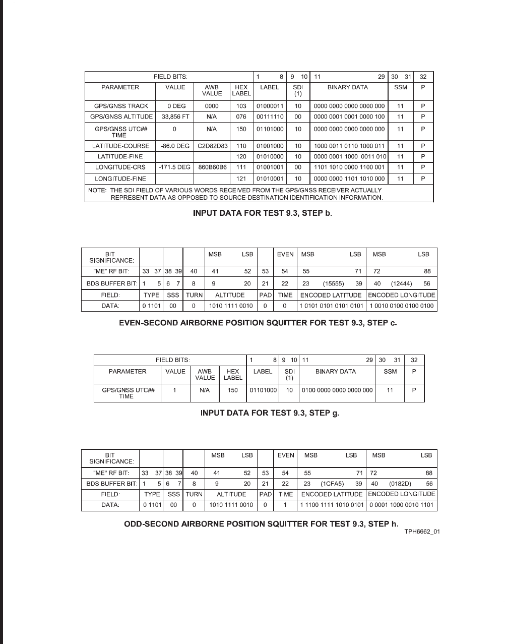
ROCKWELL COLLINS
COMPONENT MAINTENANCE MANUAL with IPL
TDR-94, PART NO 622-9352
Airborne Position Extended Squitter Test 9.3, Input Data and Results
Figure 1003/GRAPHIC 34-50-96-99B-021-A01
34-50-96 Page 1057
May 18/06
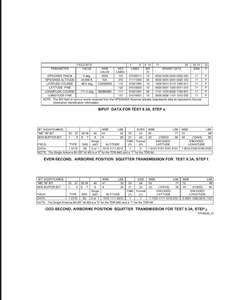
ROCKWELL COLLINS
COMPONENT MAINTENANCE MANUAL with IPL
TDR-94, PART NO 622-9352
GPS Bus/Airborne Position Extended Squitter/Time Tag Verification Test 9.3A, Input Data and Results
Figure 1004/GRAPHIC 34-50-96-99B-022-A01
34-50-96 Page 1058
May 18/06
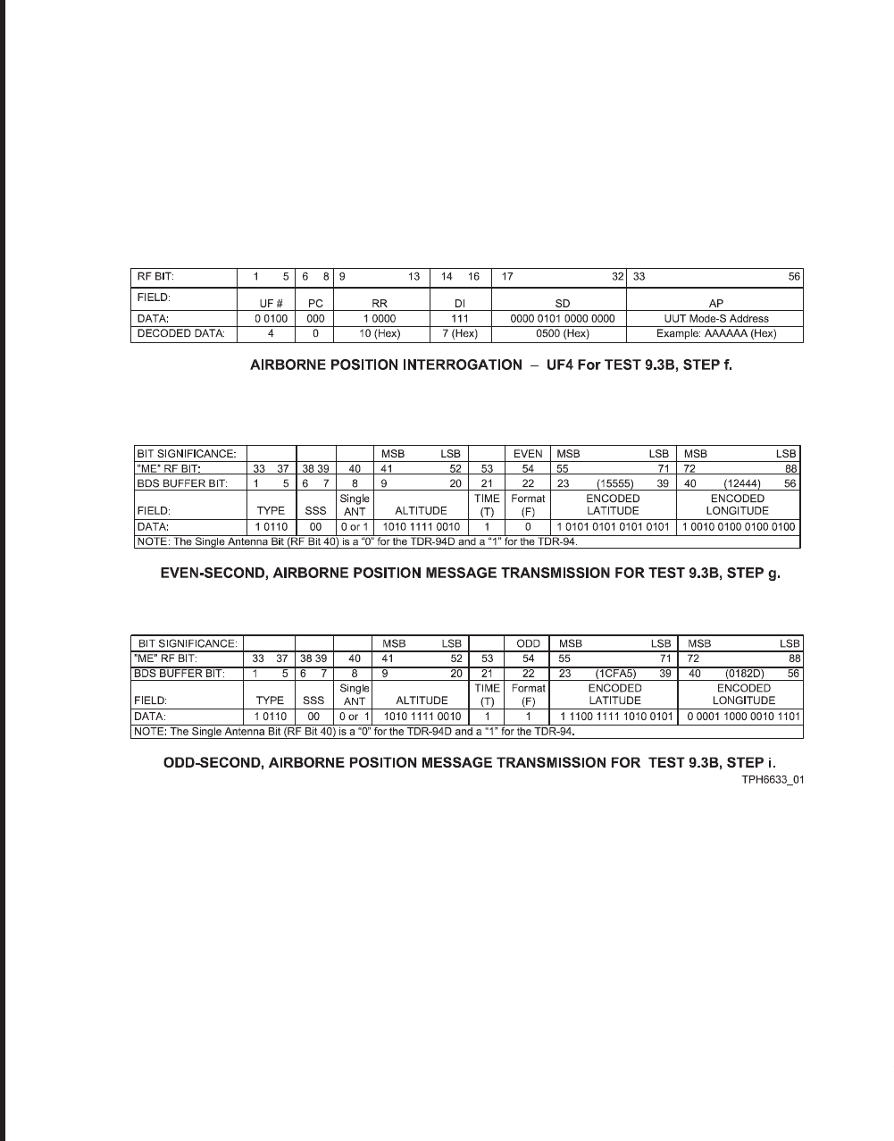
ROCKWELL COLLINS
COMPONENT MAINTENANCE MANUAL with IPL
TDR-94, PART NO 622-9352
GPS Bus/Airborne Position Extended Squitter/Time Tag Verification Test 9.3B, Input Data and Results
Figure 1005/GRAPHIC 34-50-96-99B-023-A01
34-50-96 Page 1059
May 18/06
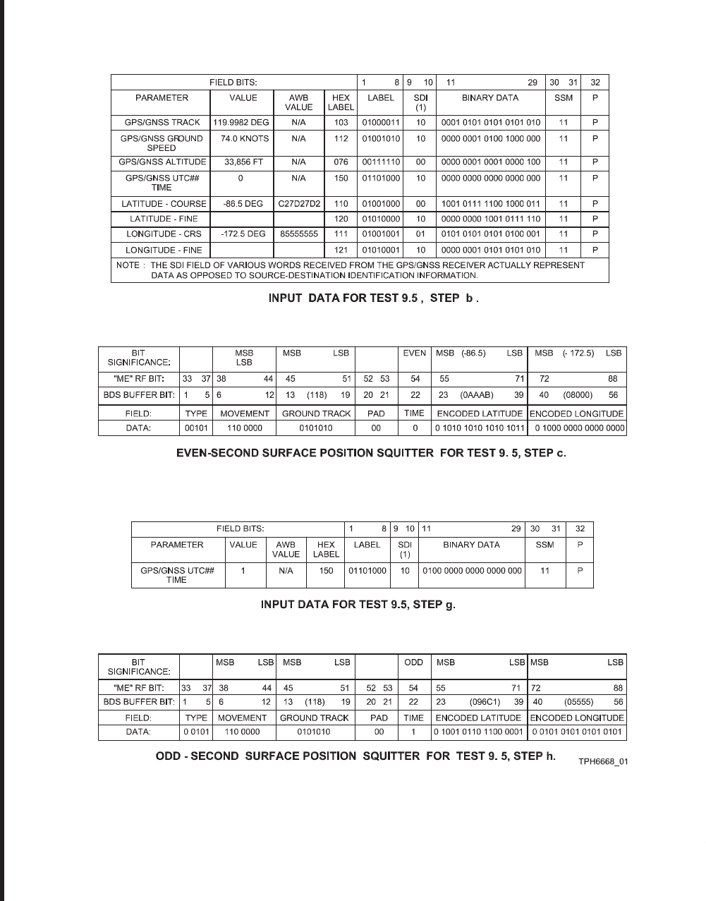
ROCKWELL COLLINS
COMPONENT MAINTENANCE MANUAL with IPL
TDR-94, PART NO 622-9352
Surface Position Extended Squitter Test 9.5, Input Data and Results
Figure 1006/GRAPHIC 34-50-96-99B-024-A01
34-50-96 Page 1060
May 18/06
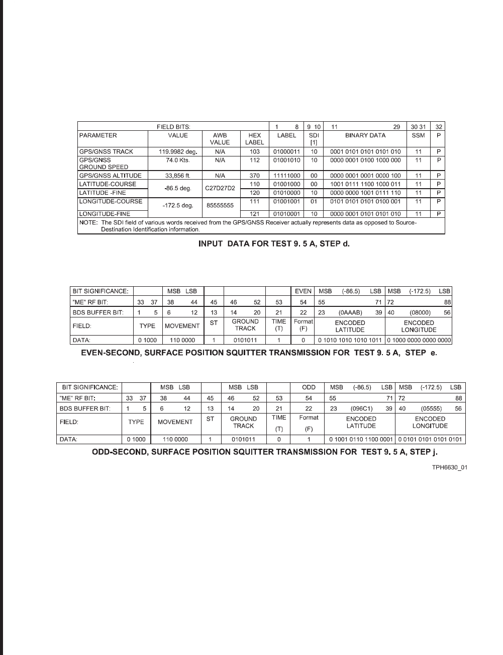
ROCKWELL COLLINS
COMPONENT MAINTENANCE MANUAL with IPL
TDR-94, PART NO 622-9352
GPS Bus/Airborne Surface Position Extended Squitter/Time Tag Verification
Test 9.5A, Input Data and Results
Figure 1007/GRAPHIC 34-50-96-99B-025-A01
34-50-96 Page 1061
May 18/06
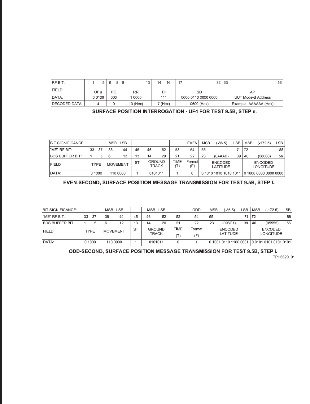
ROCKWELL COLLINS
COMPONENT MAINTENANCE MANUAL with IPL
TDR-94, PART NO 622-9352
GPS Bus/Airborne Surface Position Extended Squitter/Time Tag Verification
Test 9.5B, Input Data and Results
Figure 1008/GRAPHIC 34-50-96-99B-026-A01
34-50-96 Page 1062
May 18/06
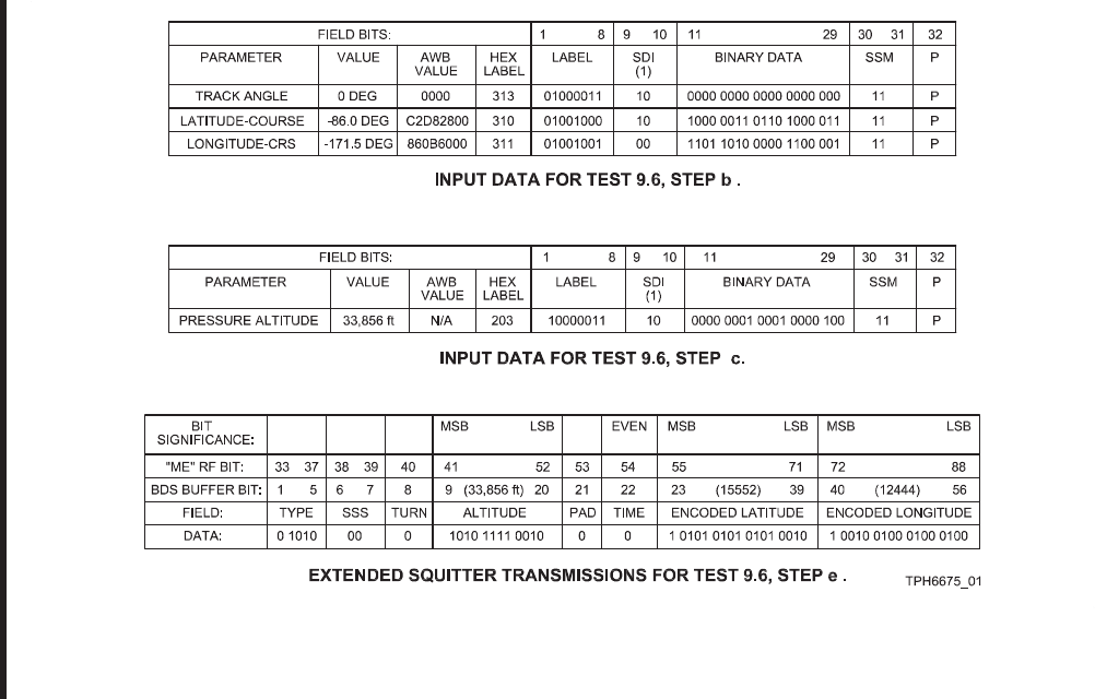
ROCKWELL COLLINS
COMPONENT MAINTENANCE MANUAL with IPL
TDR-94, PART NO 622-9352
FMS/INS Primary Data Test 9.6, Input Data and Results
Figure 1009/GRAPHIC 34-50-96-99B-027-A01
34-50-96 Page 1063
May 18/06
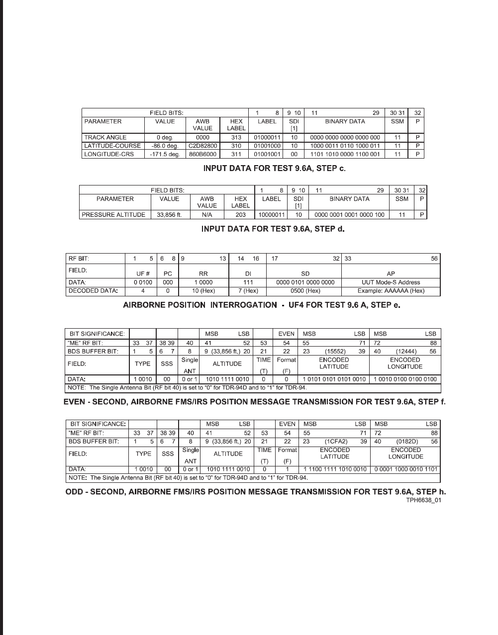
ROCKWELL COLLINS
COMPONENT MAINTENANCE MANUAL with IPL
TDR-94, PART NO 622-9352
FMS/INS Primary Data Test 9.6A, Input Data and Results
Figure 1010/GRAPHIC 34-50-96-99B-028-A01
34-50-96 Page 1064
May 18/06
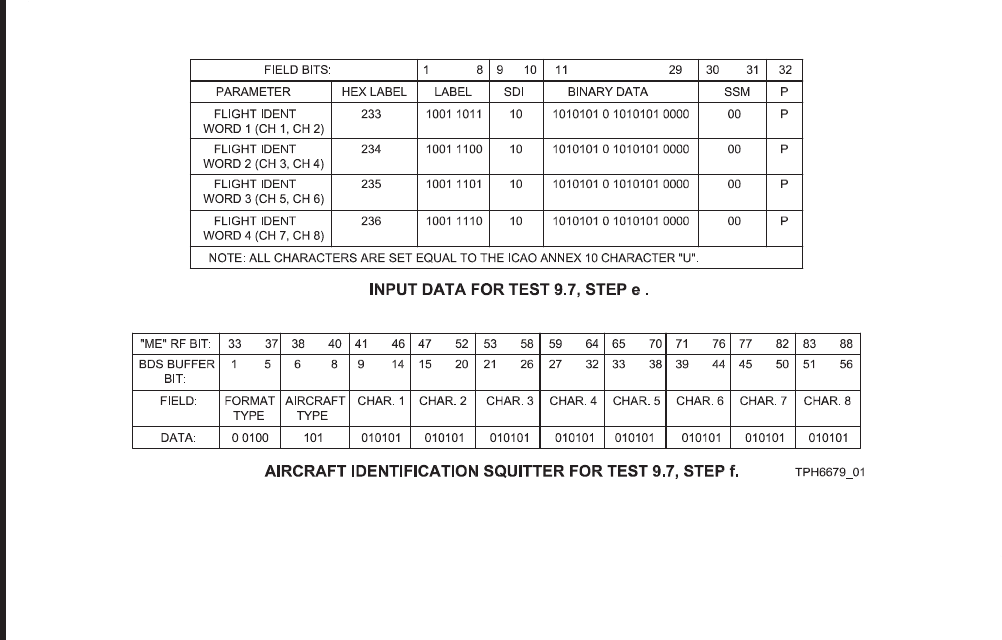
ROCKWELL COLLINS
COMPONENT MAINTENANCE MANUAL with IPL
TDR-94, PART NO 622-9352
Aircraft Identification Squitter Test 9.7, Input Data and Results
Figure 1011/GRAPHIC 34-50-96-99B-029-A01
34-50-96 Page 1065
May 18/06
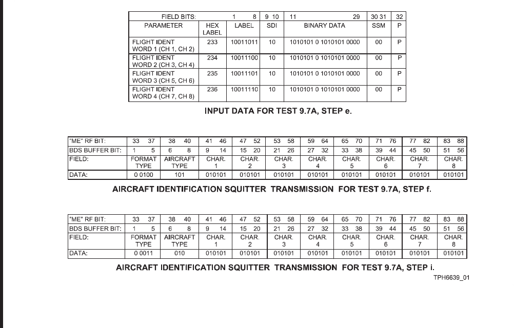
ROCKWELL COLLINS
COMPONENT MAINTENANCE MANUAL with IPL
TDR-94, PART NO 622-9352
Aircraft Identification Squitter Test 9.7A, Input Data and Results
Figure 1012/GRAPHIC 34-50-96-99B-030-A01
34-50-96 Page 1066
May 18/06
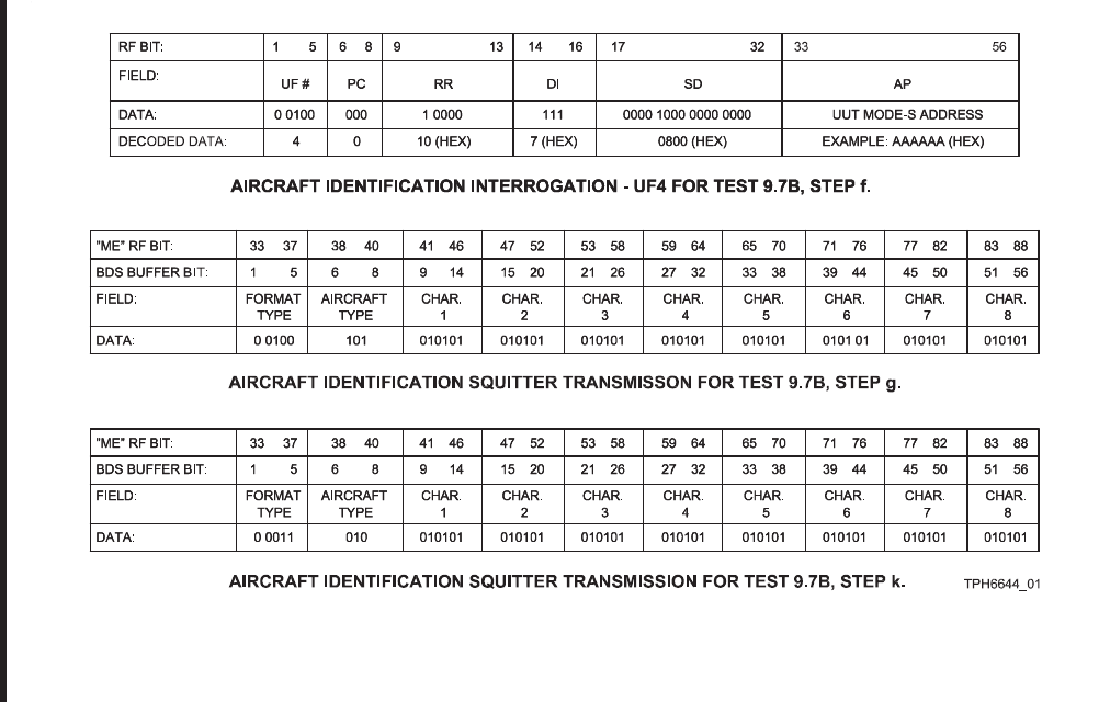
ROCKWELL COLLINS
COMPONENT MAINTENANCE MANUAL with IPL
TDR-94, PART NO 622-9352
Aircraft Identification Message Test 9.7B, Input Data and Results
Figure 1013/GRAPHIC 34-50-96-99B-031-A01
34-50-96 Page 1067
May 18/06
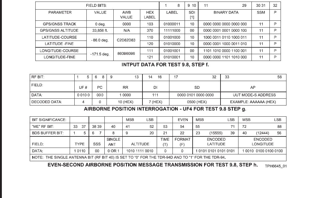
ROCKWELL COLLINS
COMPONENT MAINTENANCE MANUAL with IPL
TDR-94, PART NO 622-9352
AIS/ADSS Primary Data Test 9.8, Input Data and Results
Figure 1014/GRAPHIC 34-50-96-99B-032-A01
34-50-96 Page 1068
May 18/06
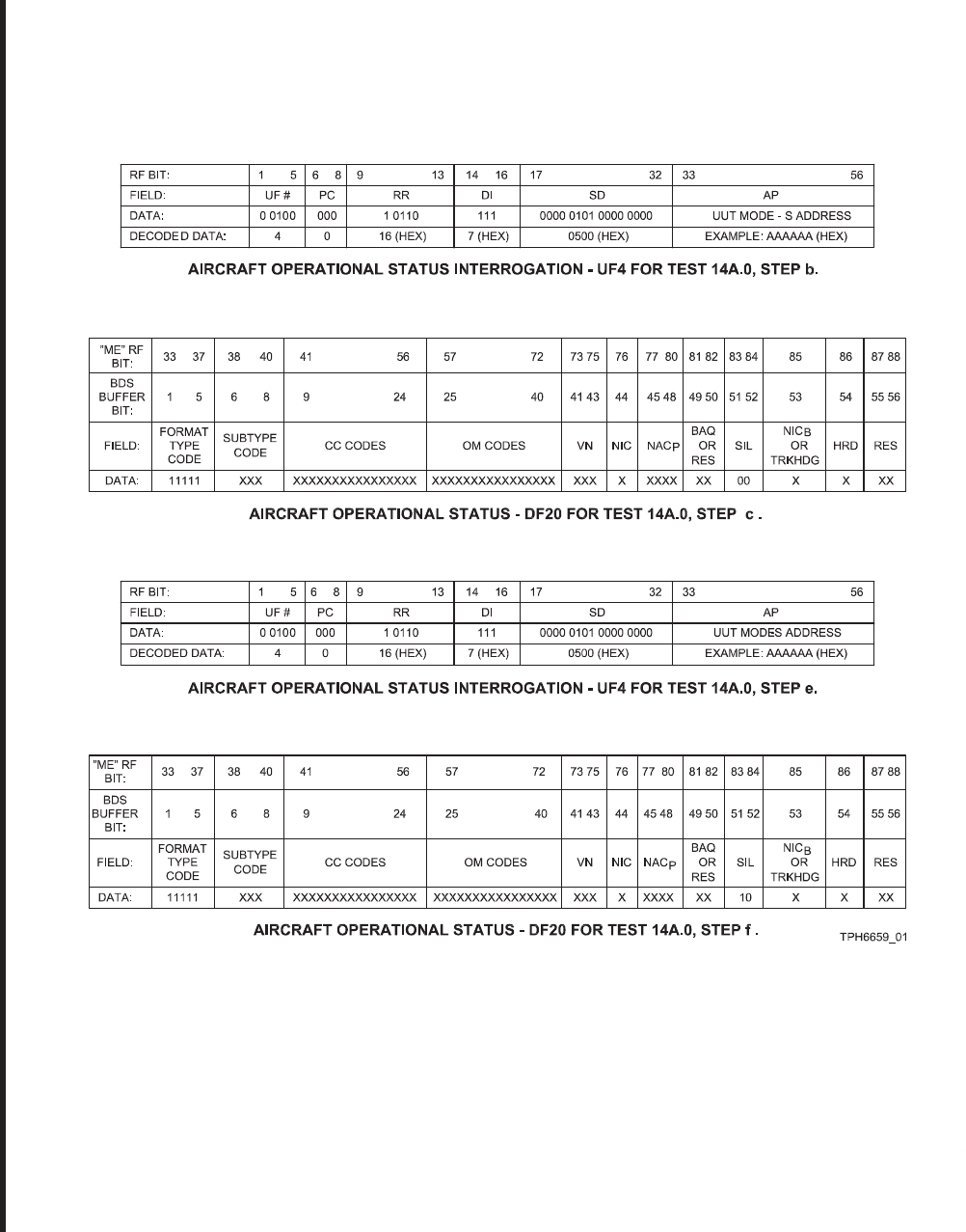
ROCKWELL COLLINS
COMPONENT MAINTENANCE MANUAL with IPL
TDR-94, PART NO 622-9352
SIL Designator Requirements Test 14A.0, Input Data and Results
Figure 1015/GRAPHIC 34-50-96-99B-033-A01
34-50-96 Page 1069
May 18/06
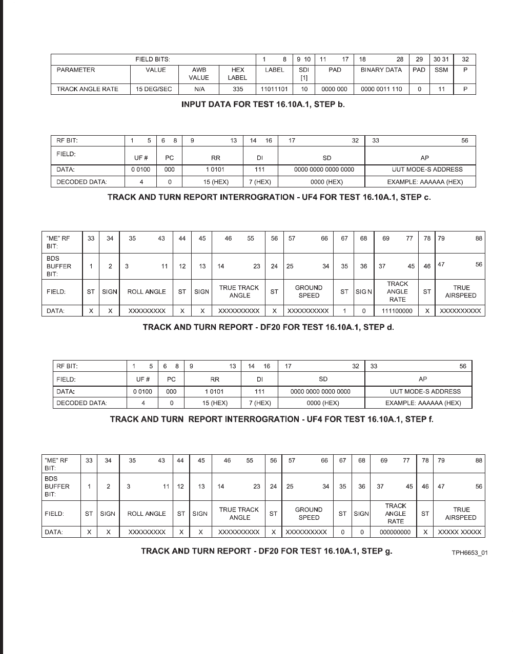
ROCKWELL COLLINS
COMPONENT MAINTENANCE MANUAL with IPL
TDR-94, PART NO 622-9352
Configuration Select S0 Discrete Test 16.10A.1, Input Data and Results
Figure 1016/GRAPHIC 34-50-96-99B-034-A01
34-50-96 Page 1070
May 18/06
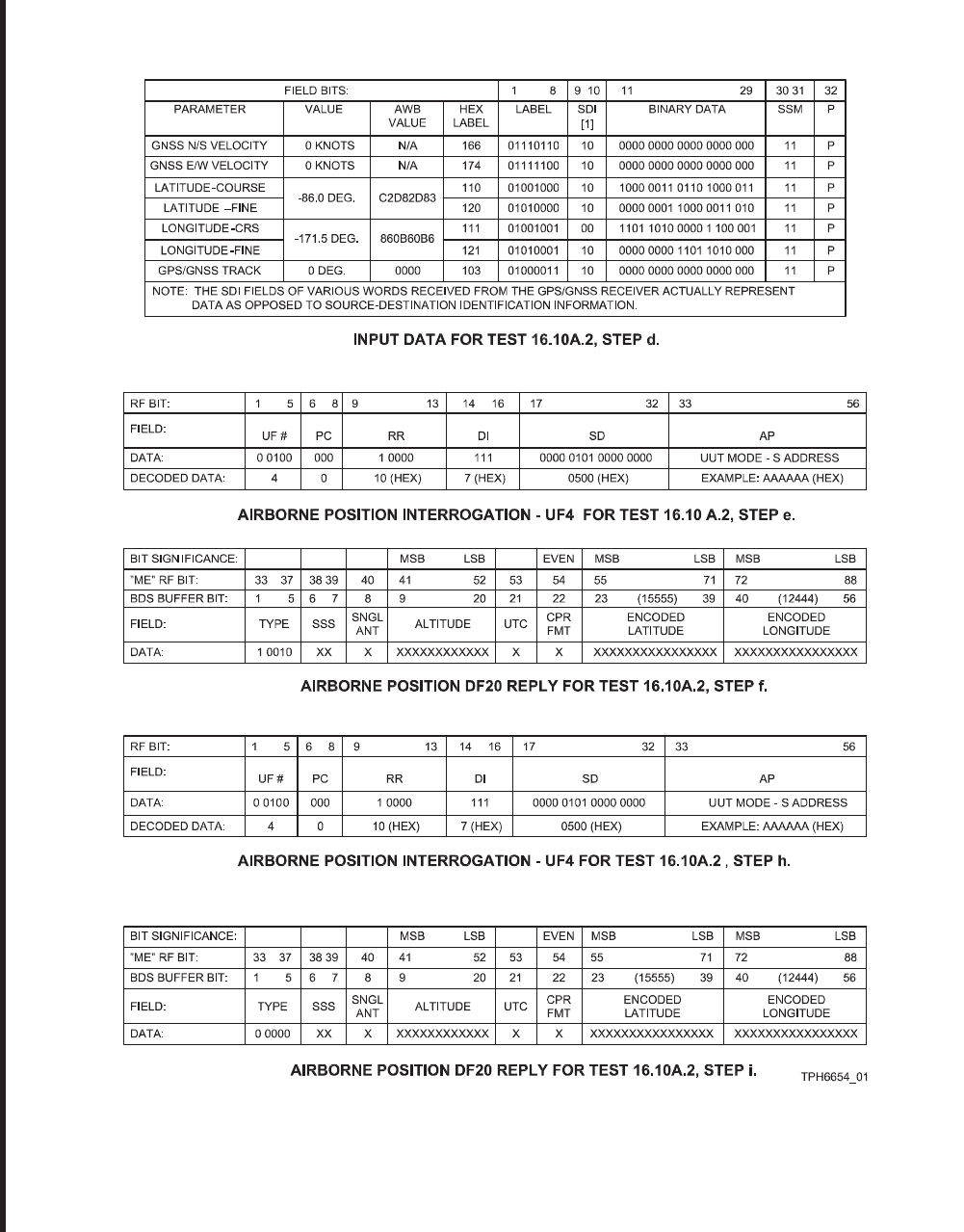
ROCKWELL COLLINS
COMPONENT MAINTENANCE MANUAL with IPL
TDR-94, PART NO 622-9352
Configuration Select S1 Discrete Test 16.10A.2, Input Data and Results
Figure 1017/GRAPHIC 34-50-96-99B-035-A01
34-50-96 Page 1071
May 18/06
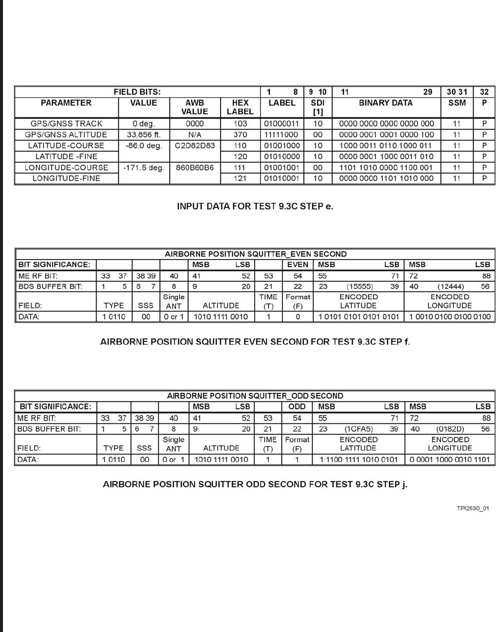
ROCKWELL COLLINS
COMPONENT MAINTENANCE MANUAL with IPL
TDR-94, PART NO 622-9352
Airborne Position Extended Squitter Test 9.3C, Input Data and Results
Figure 1018/GRAPHIC 34-50-96-99B-089-A01
34-50-96 Page 1072
May 07/07
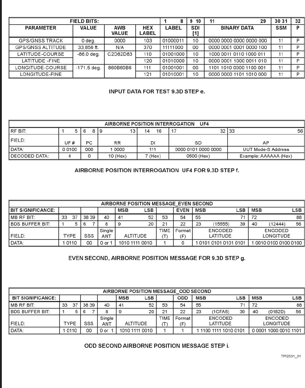
ROCKWELL COLLINS
COMPONENT MAINTENANCE MANUAL with IPL
TDR-94, PART NO 622-9352
GPS Bus / Airborne Position Extended Squitter / Time Tag Test 9.3D, Input Data and Results
Figure 1019/GRAPHIC 34-50-96-99B-090-A01
34-50-96 Page 1072.1
May 07/07
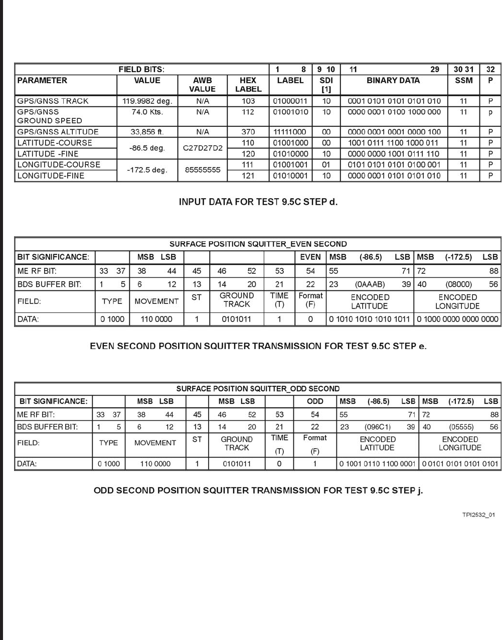
ROCKWELL COLLINS
COMPONENT MAINTENANCE MANUAL with IPL
TDR-94, PART NO 622-9352
GPS Bus / Surface Position Extended Squitter / Time Tag Verification Test 9.5C, Input Data and Results
Figure 1020/GRAPHIC 34-50-96-99B-091-A01
34-50-96 Page 1072.2
May 07/07
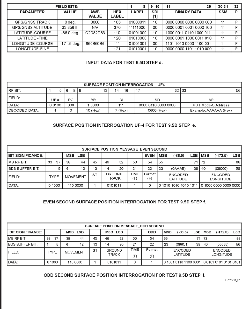
ROCKWELL COLLINS
COMPONENT MAINTENANCE MANUAL with IPL
TDR-94, PART NO 622-9352
GPS Bus / Surface Position Extended Squitter / Time Tag Verification Test 9.5D
Figure 1021/GRAPHIC 34-50-96-99B-092-A01
34-50-96 Page 1072.3
May 07/07
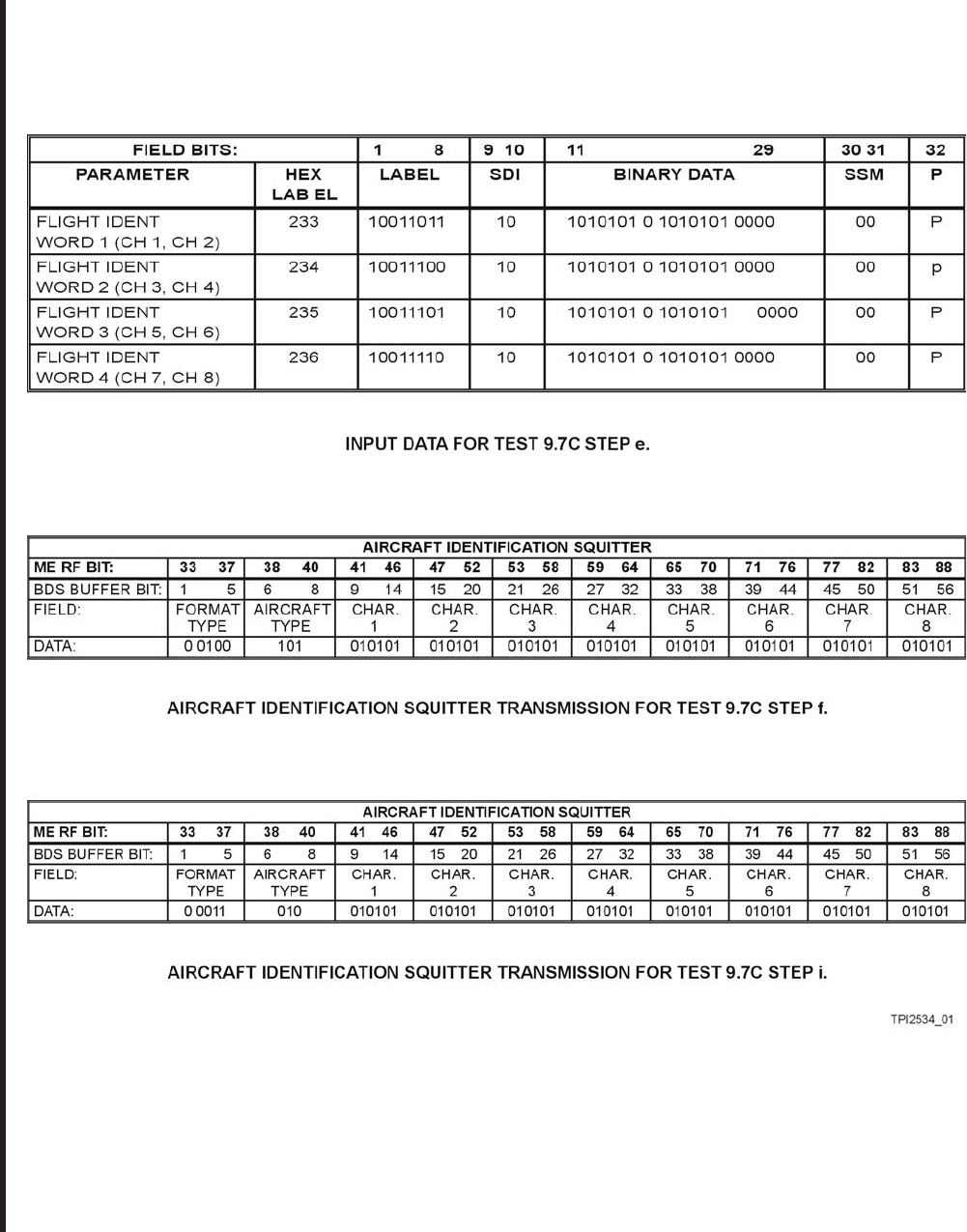
ROCKWELL COLLINS
COMPONENT MAINTENANCE MANUAL with IPL
TDR-94, PART NO 622-9352
Aircraft Identification Massage (-408 ONLY) Test 9.7C
Figure 1022/GRAPHIC 34-50-96-99B-093-A01
34-50-96 Page 1072.4
May 07/07
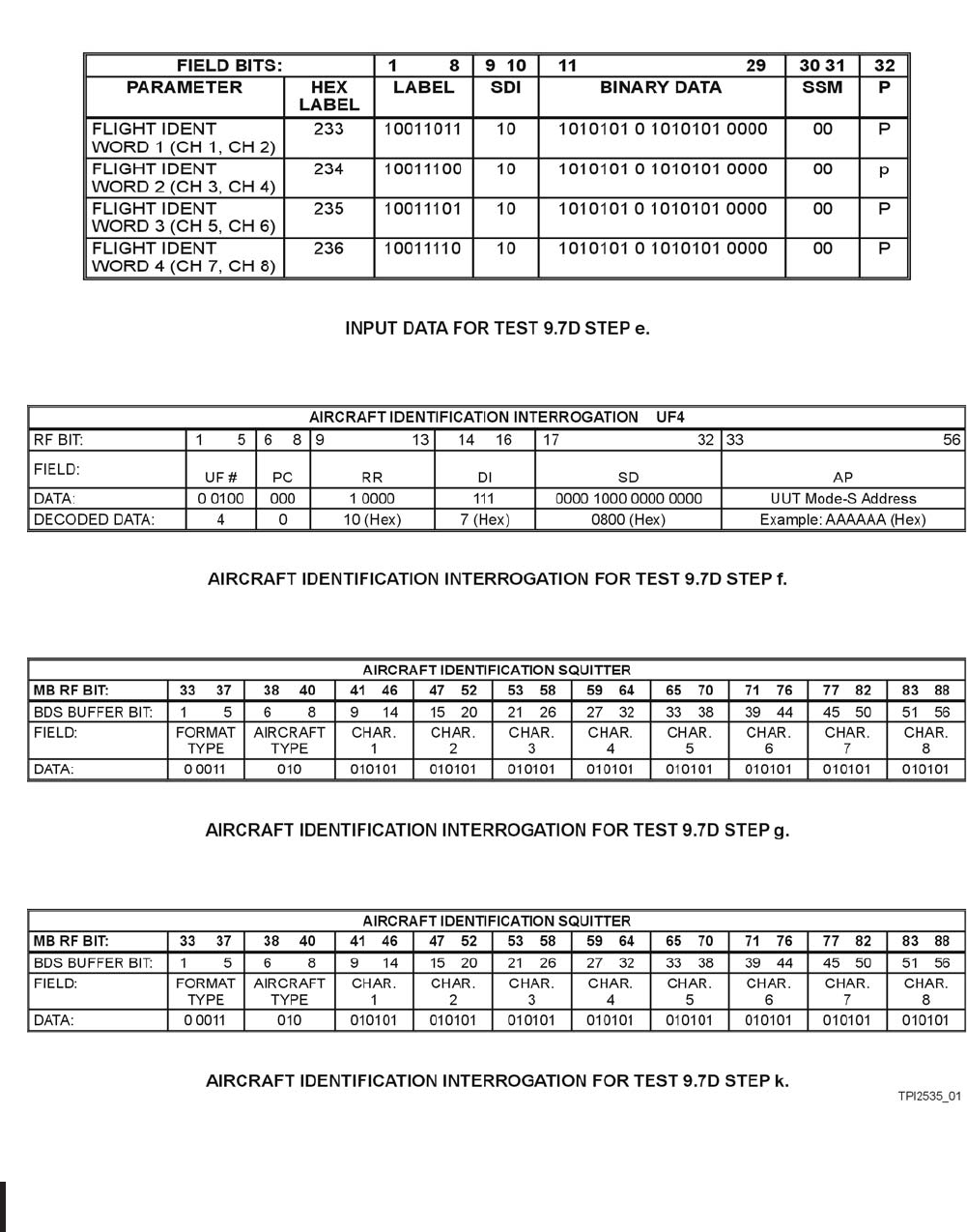
ROCKWELL COLLINS
COMPONENT MAINTENANCE MANUAL with IPL
TDR-94, PART NO 622-9352
Aircraft Identification Massage (-308, -309 ONLY) Test 9.7D
Figure 1023/GRAPHIC 34-50-96-99B-094-A01
34-50-96 Page 1072.5
Jun 20/08
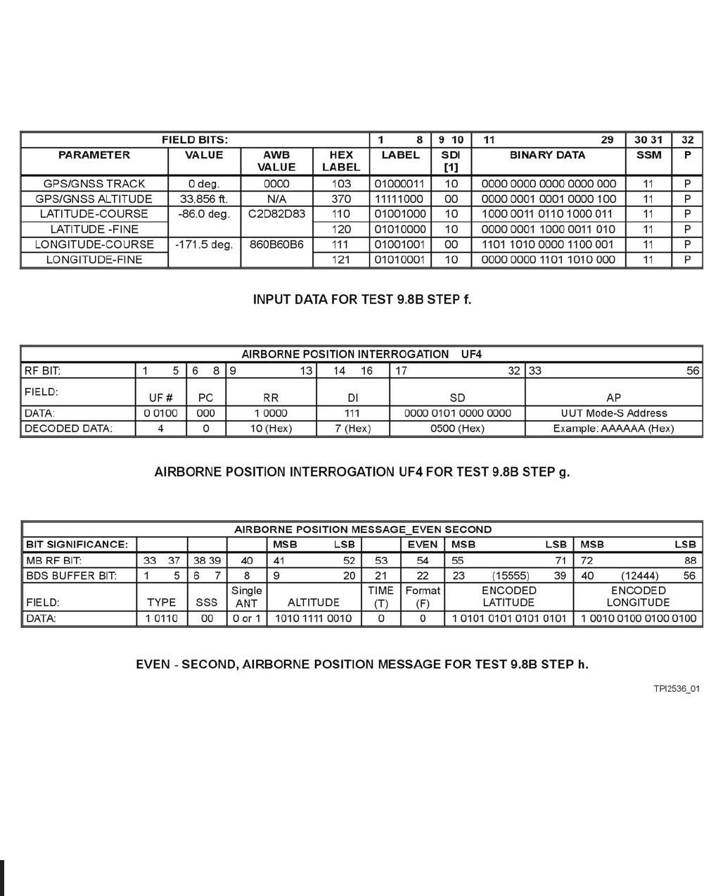
ROCKWELL COLLINS
COMPONENT MAINTENANCE MANUAL with IPL
TDR-94, PART NO 622-9352
AIS/ADSS Primary Data (-308, -309, -408, -409) Test 9.8B
Figure 1024/GRAPHIC 34-50-96-99B-095-A01
34-50-96 Page 1072.6
Jun 20/08

ROCKWELL COLLINS
COMPONENT MAINTENANCE MANUAL with IPL
TDR-94, PART NO 622-9352
SUBTASK 34-50-96-810-005-A01
B. TDR-94/94D Alignment Procedures
STEP PROCEDURE DESIRED RESULTS
0.0 SETUP INSTRUCTIONS
0.1 Remove UUT dust cover. Connect TDR-94/94D as shown
in Figure 1002/GRAPHIC 34-50-96-99B-036-A01 or Figure
1001/GRAPHIC 34-50-96-99B-020-A01. Test equipment item
numbers (XX) that appear in the test setup diagrams are identified
in Table 9003/Table 34-50-96-99A-042-A01 or Table 9002/Table
34-50-96-99A-032-A01 of the Special Tools, Fixtures, and
Equipment section.
0.2 Set up IFR 1400C front panel as follows:
SWITCH POSITION
DISPLAY SELECT FREQ MHZ
DME REPLY EFFICENXPDR MODE C
TAC A N O F F
DBL INTERR 000.0
/INTRF PULSE OFF
PRF 50
SQTR ON
IDENT OFF
F2/P2-F1/P1 F2/P2
XPDR P2/P3 DEV 0.00
P2,P3 CAL,CAL
FREQ 1030
FUNCTION SELECT XPDR
DELTA F 0.00 OFF
DMEP2DEV,P2 0.0,CAL
XPDR PULSE WIDTH 0.80 CAL
SLS/ECHO -0, OFF
RANGE/VEL/ACCEL 00000
IN/OUT, -1 NMI/NORM OUT, NORM
RF LEVEL -DBM 90
CW/NORM/OFF NORM
SUPPRESSOR OFF
SYNC T0/TAC/TD T0
SUPPRESSOR VAR ADJ to 15V P-P
CAL MARKS 1.45 US
AUTO MAN/MAN STEP MAN
FREQ STEP RATE OFF
Alignment Procedure Cont.
Table 1002/Table 34-50-96-99A-010-A01
34-50-96 Page 1072.7/1072.8
May 07/07

ROCKWELL COLLINS
COMPONENT MAINTENANCE MANUAL with IPL
TDR-94, PART NO 622-9352
STEP PROCEDURE DESIRED RESULTS
0.3 Set up rear of ATC-1400C/S1403C test set as follows:
SWITCH POSITION
DECODER NARROW
EQUALIZER OFF
SELF-INTERR OFF
INST DIM LOW
ADDRESS 10101100
0.4 Set up front panel of 5359A time synthesizer as follows:
SWITCH POSITION
SLOPE N
LEVEL +2V
SYNC DELAY PRESET
OUTPUT POLARITY NORM, POS
AMPLITUDE ADJ to 2.5V
OFFSET OFF, 0
0.5 Set up rear of 5359A time synthesizer as follows:
SWITCH POSITION
EXT TIMING DISABLE
EVENTS,SLOPE P
FREQ-STD INT
ADDRESS 0001000
NOTE: Interrogation power levels and transmitter output power
levels specified in this document are referenced to the
rear connector(s) of the Unit Under Test (UUT). The
insertion loss of coaxial cables between the UUT and
the test equipment must be accounted for.
NOTE: Perform alignment steps 1.X for Receiver IF/LVPS
Assembly, CPN 687-0727-004. Perform alignment steps
2.X for Receiver IF/LVPS Assembly, CPN 687-0727-005.
1.0 Receiver IF/LVPS Assembly, Alignment for CPN 687-0727-004 or prior.
1.1 Monitor the +5 V dc output at J7-26 with a DVM. Adjust A7R507 if
necessary
Verify a reading between 4.99
to 5.01 V dc.
1.2 Monitor J7-33 on Video Processor A6 with an oscilloscope.
Alignment Procedure Cont.
Table 1002/Table 34-50-96-99A-010-A01
34-50-96 Page 1073
Apr 17/07

ROCKWELL COLLINS
COMPONENT MAINTENANCE MANUAL with IPL
TDR-94, PART NO 622-9352
STEP PROCEDURE DESIRED RESULTS
1.3 Set the MODE-S test set to generate ATCRBS MODE-C
interrogations and apply to the bottom antenna connector. Set the
interrogation rate to 450 per second
1.4 a. Set the MODE-S test set signal strength to -79 dBm. Monitor
the Bottom Video signal at A6P22-Pin 33. Adjust A7R131 fully
clockwise.
NOTE: Theoscilloscopemustbesettotheaveraging
mode to properly measure the video pulse at the
low signal levels required.
Adjust A7R140 for an
observed video level of 0.7
volts peak.
b. Set the MODE-S test set signal strength to -77 dBm. Adjust A7R131 for an
observed video level of 0.7
volts peak.
c. Verify that the reply rate is between 90% and 100%. If not,
readjust A7R140 for desired result.
Reply rate is between 90%
and 100%.
1.5 Set the signal strength to -31 dBm. Adjust A7R133 for desired
results.
Amplitude of the P1 pulse at
J7-33 is 5.00 ±0.05 volts.
1.6 Repeat steps 1.4 and 1.5 as required.
1.7 Monitor the positive end of A6C67 on top side of the card.
1.8 Interrogate with a normal MODE-S signal at -27 dBm. Adjust
A6R118 until the ditch-slope waveform resulting from P1 has the
desired results.
16.2 ±0.2 microseconds wide
at its base.
1.9 Do steps 1.10 thru 1.16 for the TDR-94D only. Apply MODE-C
interrogations to the UUT top antenna connector.
1.10 a. Set the MODE-S test set signal strength to -79 dBm. Monitor
the Top Video signal at A6P22-Pin 31. Adjust A7R124 fully
clockwise.
NOTE: Theoscilloscopemustbesettotheaveraging
mode to properly measure the video pulse at the
low signal levels required.
Adjust A7R111 for an
observed video level of 0.7
volts peak.
b. Set the MODE-S test set signal strength to -77 dBm. Adjust A7R124 for an
observed video level of 0.7
volts peak.
Alignment Procedure Cont.
Table 1002/Table 34-50-96-99A-010-A01
34-50-96 Page 1074
May 18/06

ROCKWELL COLLINS
COMPONENT MAINTENANCE MANUAL with IPL
TDR-94, PART NO 622-9352
STEP PROCEDURE DESIRED RESULTS
1.11 Verify that the reply rate is between 90% and 100%. If not,
readjust A7R111 for a reply rate between 90% and 100%.
NOTE: If the Minimum Trigger Level (MTL) cannot be established
within the specified limits, or if the MTL does not
stay within the specified limits over the operational
temperature range, the A7R127 (for the Top channel)
and/or A7R137 (for the Bottom channel) (CPN
705-3543-020) may be added as needed.
1.12 Set the MODE-S test set signal strength for -31 dBm. Adjust
A7R123 for desired results.
Amplitude of the P1 pulse at
J7-31is5.00±0.05volts.
1.13 Repeat steps 1.11 and 1.12 as required.
1.14 a. Set the MODE-S test set signal strength to -50 dBm. Measure
and note the amplitude of the P1 pulse at J7-31.
b. Apply the same input signal level to the bottom channel.
Measure and note the amplitude of the P1 pulse at J7-33.
c. Verify that the two amplitudes are within 0.1 volts of each
other. If this is not the case, reduce the stronger of the two
measurements by adjusting the appropriate Slope Adjust,
A7R123 or A7R133, until the difference is less than 0.1 volts.
NOTE: If this readjustment is performed, then the MTL
must be readjusted in accordance with either step
1.4 or 1.11, whichever is appropriate for the Top or
Bottom channel requiring adjustment.
____ V
_____V
Voltagedifferenceshouldbe
less than 0.1 volt
1.15 Monitor the positive end of A6C59 on the Video Processor board.
1.16 Set the MODE-S test set signal strength to -27 dBm. Adjust
A6R117 on the Video Processor board such that the ditch-slope
waveform resulting from P1 has the desired results.
NOTE: Extra care must be taken in the adjustments made in
the following steps 1.17 through 1.19. DPSK trimmer
capacitor A7C301 adjustments should be made in very
small increments or steps. These adjustments are critical
to the performance of the UUT. Capacitor A7C301 should
only be adjusted at the board or card level (if possible).
16.2 ±0.2 ȝswideatitsbase
Alignment Procedure Cont.
Table 1002/Table 34-50-96-99A-010-A01
34-50-96 Page 1075
Apr 17/07

ROCKWELL COLLINS
COMPONENT MAINTENANCE MANUAL with IPL
TDR-94, PART NO 622-9352
STEP PROCEDURE DESIRED RESULTS
1.17 To align the DPSK Demodulator VCO, interrogate
the bottom channel with MODE-S ONLY ALL-CALL
interrogations having a signal strength of -60 dBm.
Vary the interrogation center frequency above 1030 MHz until the
reply rate reduces to 90% and note the frequency as the upper
frequency limit.
Vary the interrogation center frequency below 1030 MHz and note
the frequency as the lower frequency limit.
Adjust A7C306 such that the two limit frequencies are equidistant
from 1030.00 MHz. Verify that both frequencies are removed from
1030 MHz by at least 0.6 MHz. If exact centering of the center
frequency is difficult to achieve, the adjustment should be made
to slightly favor the higher frequency limit.
_____
_____
1.18 The IF bandwidth may be adjusted with A7R305. Adjustment
of A7R305 is critical to the performance of the unit and should
not be performed at the top-level assembly unless necessary. If
adjustment of A7R205 is necessary, then the frequency centering
adjustments performed in step 1.17 must be rechecked.
1.19 To align the DPSK demodulator VCO, interrogate the top channel
with a Mode-S Only All-Call interrogations having a signal level of
-60 dBm and a center frequency of 1030.0 MHz. Monitor A7TP303
with the oscilloscope and slowly adjustA7C352 for the cleanest
and most square observed signal pulses.
NOTE: DPSK adjustments are interactive. Steps 1.17
through 1.19 should be rechecked prior to continuing
with the following procedures.
1.20 Monitor J7-33. Interrogate the bottom channel with MODE-A
or MODE-C interrogations having a signal level of -67 dBm
and measure the video amplitude of P1 observed. Turn off all
interrogations to the UUT.
NOTE: Enable the Self-Test function and adjust A7R122 such
that the observed self-test signal P1 is equal to the video
amplitude previously observed within ±0.2 volts.
Alignment Procedure Cont.
Table 1002/Table 34-50-96-99A-010-A01
34-50-96 Page 1076
May 18/06