Siemens Canada Siemens Milltronics Process Instruments LR250 SITRANS LR 250 TANK LEVEL PROBING RADAR User Manual JE01 LR250 LUI
Siemens Canada Ltd. - Siemens Milltronics Process Instruments SITRANS LR 250 TANK LEVEL PROBING RADAR JE01 LR250 LUI
Contents
USERS MANUAL

i
mmmmm
Table of Contents
Table of Contents
Table of Contents ...............................................................................................................i
Safety Notes ...........................................................................................................................................1
Safety marking symbols ............................................................................................................1
The Manual ............................................................................................................................................1
FCC Conformity ......................................................................................................................................2
Application Examples .................................................................................................................2
Support ....................................................................................................................................................2
Abbreviations and Identifications ...........................................................................................2
SITRANS LR250 ..................................................................................................................4
Applications ..................................................................................................................................5
SITRANS LR250 System Implementation ..............................................................................6
Programming ................................................................................................................................6
SITRANS LR250 Approvals and Certificates .........................................................................6
Specifications ....................................................................................................................7
SITRANS LR250 ..................................................................................................................................... 7
Power............................................................................................................................................. 7
Performance................................................................................................................................. 7
Interface ........................................................................................................................................ 8
Mechanical................................................................................................................................... 8
Environmental .............................................................................................................................. 9
Process.......................................................................................................................................... 9
Approvals (verify against device nameplate)..................................................................... 10
Programmer (infrared keypad) .............................................................................................. 10
Installation ........................................................................................................................11
Mounting location ...............................................................................................................................12
Location on a nozzle .................................................................................................................14
Polarization reference point ...................................................................................................14
Mounting Instructions .......................................................................................................................15
Mounting: Threaded Version .................................................................................................15
Horn Location on Nozzles ....................................................................................................... 16
Mounting: Stillpipe or Bypass (Sidepipe) ............................................................................16
Pipe requirements..................................................................................................................... 16
Mounting: Horn with Extension .............................................................................................18
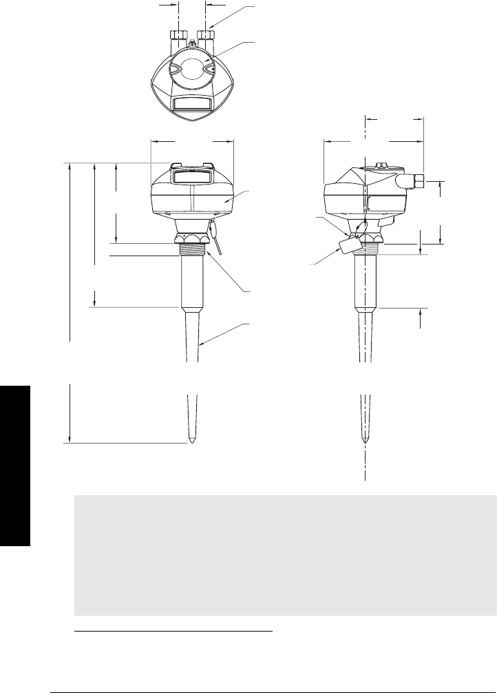
SITRANS LR250 Dimensions ..................................................................................................19
Threaded Horn Antenna.......................................................................................................... 19
Dimensions: Horn with extensions ....................................................................................... 20
Dimensions: Flanged Horn...................................................................................................... 21
Dimensions: Flanges ..........................................................................................................................22
Wiring ................................................................................................................................24
Power .....................................................................................................................................................24
Connecting SITRANS LR250 .............................................................................................................24
Wiring setups for hazardous area installations ..........................................................................25
Intrinsically Safe wiring........................................................................................................... 25
Non-incendive wiring (only for USA/Canada) ....................................................................28
Wiring drawing (Intrinsically Safe: FM/CSA) ...............................................................................29

ii
mmmmm
Table of Contents
Wiring drawing (Non-incendive: FM/CSA) ...................................................................................30
Instructions specific to hazardous area installations ................................................................31
Quick Start ........................................................................................................................33
Activating SITRANS LR250 ...............................................................................................................33
Measurement mode (RUN mode) ........................................................................................ 33
Programming SITRANS LR250 .........................................................................................................34
The handheld programmer and PROGRAM mode display .............................................34
Quick Start Wizard via the handheld programmer ...........................................................35
Level application example ................................................................................................................37
Auto False Echo Suppression ................................................................................................37
Quick Start Wizard via SIMATIC PDM .................................................................................38
Device Description (DD).......................................................................................................... 38
Quick Start Wizard steps......................................................................................................... 39
Using Linearization via the Quick Start wizard ..................................................................42
Local Operation Interface ..............................................................................................46
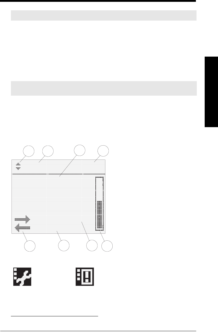
The LCD Display ..................................................................................................................................46
Key functions in Measurement mode ..................................................................................47
PROGRAM mode display......................................................................................................... 48
Navigation view......................................................................................................................... 48
Programming via the handheld programmer ...............................................................................49
Echo Profile Viewing ................................................................................................................51
Operating SITRANS LR250 via SIMATIC PDM ...........................................................52
Functions in SIMATIC PDM ..............................................................................................................52
SIMATIC PDM Rev. 6.0, SP2 Features .................................................................................52
Accessing Functions ................................................................................................................52
Online Display ............................................................................................................................ 53
Changing parameter settings using SIMATIC PDM .........................................................53
Configuring a new device .......................................................................................................54
Calibrating LR 460 via PDM ....................................................................................................54
Reset ............................................................................................................................................ 55
Configuration Flag Reset (HART only).................................................................................. 55
Auto False Echo Suppression ................................................................................................ 55
Echo profile saving.................................................................................................................... 57
Trend Diagram (Level Trend over Time).............................................................................. 57
Application Examples ....................................................................................................58
Example 1: Liquid resin in storage vessel, level measurement .....................................58
Example 2: Horizontal vessel with volume measurement ...............................................59
Parameter Reference .....................................................................................................61
Pull-down menus via SIMATIC PDM ...................................................................................61
Quick Start Wizard ..............................................................................................................................61
Appendix A: Alphabetical Parameter List ..................................................................93
Appendix B: Programming Chart ..................................................................................95
Appendix C: Troubleshooting ........................................................................................97
Communication Troubleshooting ....................................................................................................97
Generally: ....................................................................................................................................97
Specifically: .................................................................................................................................97
General Fault Codes ...........................................................................................................................98

iii
mmmmm
Table of Contents
Fault Codes ...........................................................................................................................................98
Operation Troubleshooting .............................................................................................................101
Appendix D: Maintenance ...........................................................................................104
Unit Repair and Excluded Liability ................................................................................................104
Appendix E: Technical Reference ..............................................................................105
Principles of Operation ....................................................................................................................105
Echo Processing ...............................................................................................................................105
Measurement Response .......................................................................................................106
Typical Receiver Signal ........................................................................................................ 106
Echo Lock ............................................................................................................................................107
Loss of Echo (LOE) ..................................................................................................................107
Fail-safe Mode ...................................................................................................................................107
Fail-safe Timers .......................................................................................................................107
Fail-safe value ..........................................................................................................................107
Far Range (Range Extension) .........................................................................................................108
False-Echo Suppression .................................................................................................................108
Near Range (Blanking) ..........................................................................................................108
Auto False-Echo Suppression ..............................................................................................108
mA Output ...........................................................................................................................................110
Maximum Process Temperature Chart .....................................................................111
Process Pressure/Temperature derating curves ................................................................112
Horn Antenna or Wave Guide – ANSI Hole Pattern, 150# ............................................113
Horn Antenna or Wave Guide DN Hole Pattern, PN16 ..................................................113
Appendix F: Loop power ..............................................................................................114
Typical Connection Drawing ................................................................................................114
Allowable operating area of SITRANS LR250 ..................................................................114
Curve 1 (General Purpose, Intrinsically Safe, Non-incendive) ....................................114
Curve 2 (Flameproof, Increased Safety, Explosion-proof) ............................................115
Startup Curve ...........................................................................................................................115
Appendix G: Special Applications .............................................................................116
Application Example: Stillpipe ..............................................................................................116
Appendix H: HART Communications ........................................................................117
SIMATIC PDM ...................................................................................................................................117
HART Device Description (DD) ......................................................................................................117
HART Communicator 375 ......................................................................................................118
Supported HART Commands: ........................................................................................................121
Universal and Common Practice Commands ..................................................................121
Device Specific Commands ..................................................................................................121
Appendix L: Software Revision History ....................................................................122
Glossary ..........................................................................................................................123
Index ................................................................................................................................127
LCD menu structure ......................................................................................................130

iv
mmmmm
Table of Contents
7ML19985JE01 SITRANS LR250 (HART) – INSTRUCTION MANUAL Page 1
mmmmm
SITRANS LR250
Safety Notes
Special attention must be paid to warnings and notes highlighted from the rest of the text
by grey boxes.1
Safety marking symbols
The Manual
This manual will help you set up your SITRANS LR250 for optimum performance. We
always welcome suggestions and comments about manual content, design, and
accessibility. Please direct your comments to techpubs.smpi@siemens.com.
For other Siemens Milltronics level measurement manuals, go to:
www.siemens.com/level and look under Level Measurement..
WARNING: relates to a caution symbol on the product, and means
that failure to observe the necessary precautions can result in death,
serious injury, and/or considerable material damage.
WARNING1: means that failure to observe the necessary
precautions can result in death, serious injury, and/or considerable
material damage.
Note: means important information about the product or that part of the operating
manual.
1. This symbol is used when there is no corresponding caution symbol on the product.
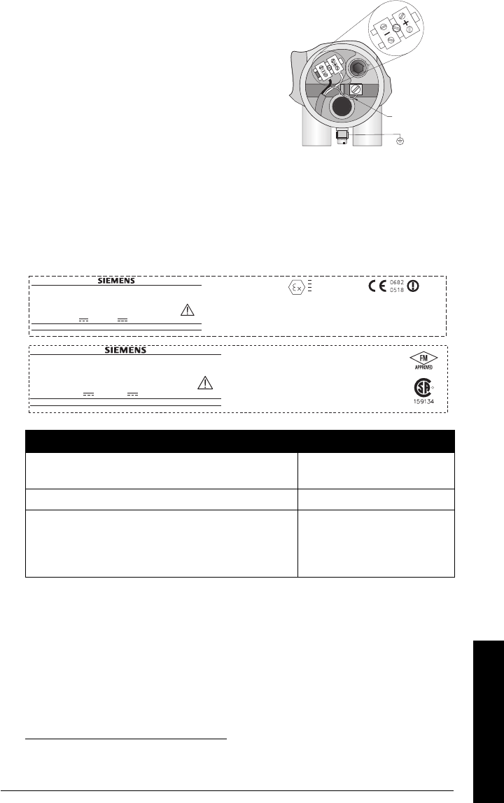
In manual On product Description
Earth (ground) Terminal
Protective Conductor Terminal
(Label on product: yellow background.) WARNING: refer
to accompanying documents (manual) for details.
Notes:
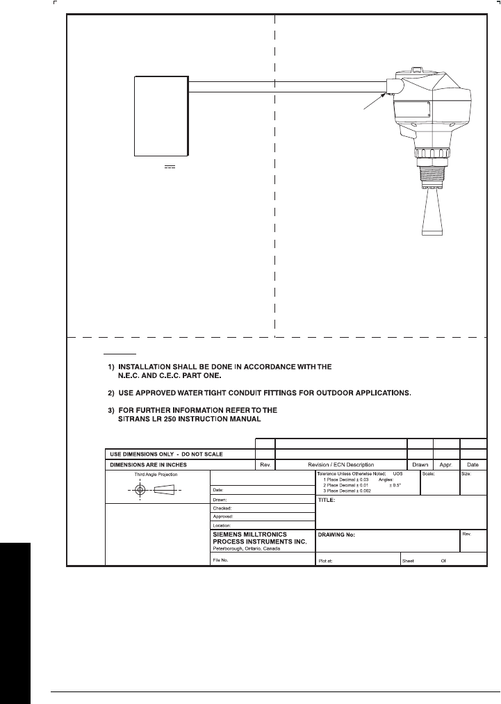
• Please follow the installation and operating procedures for a quick, trouble-free
installation and to ensure the maximum accuracy and reliability of your SITRANS LR250.
• This manual applies to the SITRANS LR250 (HART) only.

Page 2 SITRANS LR250 (HART) – INSTRUCTION MANUAL 7ML19985JE01
mmmmm
SITRANS LR250
FCC Conformity
US Installations only: Federal Communications Commission (FCC) rules
Application Examples
The application examples used in this manual illustrate typical installations using
SITRANS LR250. Because there is often a range of ways to approach an application,
other configurations may also apply.
In all examples, substitute your own application details. If the examples do not apply to
your application, check the applicable parameter reference for the available options.
Standard applications are found in the main body of the manual: for more specialized
applications, please see
Appendix G: Special Applications
, page 116.
Support
If you have questions you can access our 24-hour hotline at:
www.siemens.com/automation/support-request
Phone: +49 180 50 50 222.
Abbreviations and Identifications
WARNING: Changes or modifications not expressly approved by
Siemens Milltronics could void the user’s authority to operate the
equipment.
Notes:
• This equipment has been tested and found to comply with the limits for a Class A
digital device, pursuant to Part 15 of the FCC Rules. These limits are designed to
provide reasonable protection against harmful interference when the equipment is
operated in a commercial environment.
• This equipment generates, uses, and can radiate radio frequency energy and, if not
installed and used in accordance with the instruction manual, may cause harmful
interference to radio communications. Operation of this equipment in a residential
area is likely to cause harmful interference to radio communications, in which case
the user will be required to correct the interference at his own expense.
Short
form Long Form Description Units
A/D Analog to digital
CE / FM /
CSA
Conformitè Europèene /
Factory Mutual / Canadian
Standards Association
safety approval

7ML19985JE01 SITRANS LR250 (HART) – INSTRUCTION MANUAL Page 3
mmmmm
SITRANS LR250
CiInternal capacitance
D/A Digital to analog
DAC Digital Analog Converter
DCS Distributed Control System control room apparatus
FV Full Vacuum
ESD Electrostatic Discharge
HART Highway Addressable
Remote Transducer
IiInput current mA
IoOutput current mA
IS Intrinsically Safe safety approval
LiInternal inductance mH
LRV Lower Range Value value for process empty level 4 mA1
LSL Lower Sensor Limit below which no PV is
anticipated
mH milliHenry 10-3 Henry
µF microFarad 10-6 Farad
µsmicrosecond 10-6 Second
PED Pressure Equipment
Directive safety approval
pF pico Farads 10-12 Farad
ppm parts per million
PV Primary Variable measured value
SV Secondary Variable equivalent value
TVT Time Varying Threshold sensitivity threshold
UiInput voltage V
UoOutput voltage V
URV Upper Range Value value for process full level 20 mA1
USL Upper Sensor Limit above which no PV is
anticipated
1. 100% is most commonly set to 20 mA, and 0% to 4 mA: however, the settings
can be reversed.
Short
form Long Form Description Units

Page 4 SITRANS LR250 (HART) – INSTRUCTION MANUAL 7ML19985JE01
mmmmm
SITRANS LR250
SITRANS LR250
SITRANS LR250 is a 2-wire loop-powered, continuous level measuring instrument that
utilizes advanced pulse radar technology at 25 GHz. The instrument consists of an
electronic component coupled to the antenna and process connection. It is very easy to
install and set up, using either the infrared hand-held programmer locally, or using
SIMATIC PDM from a remote location.
Communication is via HART1. Signals are processed using Process Intelligence which
has been field-proven in over 500,000 applications worldwide (ultrasonic and radar).
SITRANS LR250 is available in numerous versions, several of which are approved for use
in hazardous areas. The approval rating is shown on the device nameplate.
Process Connections
The device is available with threaded or flange type process connections with a horn
antenna.
1. HART® is a registered trademark of the HART Communication Foundation.
Application
Type
LR250
Version Approval Rating Valid for: Wiring
Non-
hazardous
General
Purpose
CSAUS/C, FM, CE US/Canada,
Europe
See
page 29
Hazardous
Intrinsically
Safe (barrier
required)
ATEX II 1 G, EEx ia IIC T4
ATEX 1D, EEx tD A20 IP67 T90 °C Europe
See
page 29
IECEx SIR 05.0031X
Ex ia IIC T4
EX tD A20 IP67 T90 °C
International
FM/CSA:
Class I, Div. 1, Groups A, B, C, D
Class II, Div. 1, Groups E, F, G
Class III T4
US/Canada See
page 29
Non-
incendive
FM/CSA:
Class I, Div. 2, Groups A, B, C, D T5
US/Canada See
page 30
7ML19985JE01 SITRANS LR250 (HART) – INSTRUCTION MANUAL Page 5
mmmmm
SITRANS LR250
Applications
SITRANS LR250 is designed to measure liquid levels in a variety of applications:
• liquid bulk storage vessels
• simple process vessels with gentle agitation
• liquids
• slurries
Notes:
• Please refer to device nameplate for approval information.
• SITRANS LR250 is to be used only in the manner outlined in this manual, otherwise
protection provided by the equipment may be impaired.
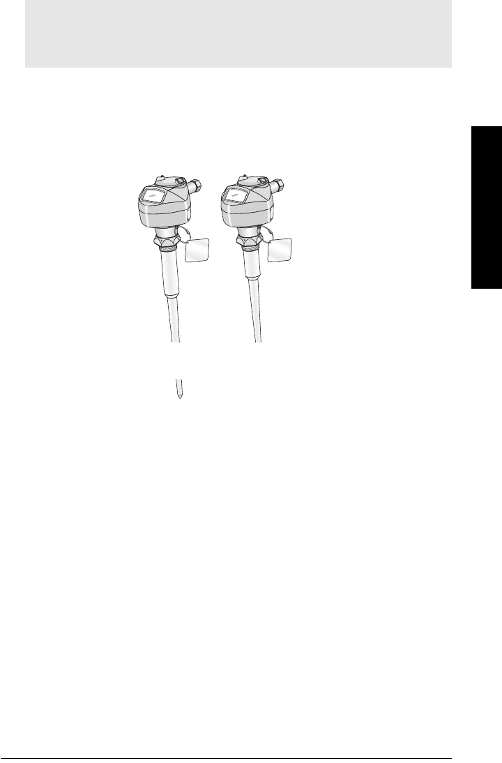
shield length: 100 mm (4"): use for
nozzles of 100 mm (4") or less in
length
shield length 250 mm (10"):
use for long nozzles of 250 mm (10")
or less in length
GRAPHIC TO BE UPDATE
D
Page 6 SITRANS LR250 (HART) – INSTRUCTION MANUAL 7ML19985JE01
mmmmm
SITRANS LR250
SITRANS LR250 System Implementation
SITRANS LR2501supports HART2communication protocol, and SIMATIC PDM software.
Programming
SITRANS LR250 carries out its level measurement function according to the set of built-in
parameters. You can make parameter changes via the hand programmer, via a PC using
SIMATIC PDM, or via a HART Handheld Communicator.
SITRANS LR250 Approvals and Certificates
1. Depending on the system design, the power supply may be separate from the
PLC, or integral to it.
2. A 250 Ohm resistor may be required if the loop resistance is less than 250 Ohms.
Note: Please see
Approvals (verify against device nameplate)
on page 10 for an
approvals listing.
active PLC
HART modem
SITRANS LR250
power supply1
Typical PLC/mA configuration with HART
R2= 250 Ω
HART
communicator
GRAPHIC TO BE UPDATE
D

7ML19985JE01 SITRANS LR250 (HART) – INSTRUCTION MANUAL Page 7
mmmmm
Specifications
Specifications
SITRANS LR250
Power
• Maximum 30 V DC
• 4 to 20 mA
Performance
Reference operating conditions according to IEC 60770-1
• ambient temperature +15 to +25 °C (+59 to +77 °F)
• humidity 45% to 75% relative humidity
• ambient pressure 860 to 1060 mbar g (86000 to 106000 N/m2 g)
Measurement Accuracy (measured in accordance with IEC 60770-1)
• non-linearity (accuracy) the greater of: 10 mm (0.4"), or 0.10% of High
Calibration point value (including hysteresis and
non-repeatability)
• non-repeatability 5 mm (included in non-linearity specification)
• deadband (resolution) 5 mm (included in non-linearity specification)
Analog Output Accuracy (measured in accordance with IEC 60770-1)
• non-linearity (accuracy) 0.125% of Span (including hysteresis and non-
repeatability)
• non-repeatability 0.025% of Span (included in non-linearity
specification)
• deadband (resolution) 0.0375% of Span (included in non-linearity
specification)
Note: Siemens Milltronics makes every attempt to ensure the accuracy of these
specifications but reserves the right to change them at any time.
Nominal 24 V DC at
max. 550 Ohm: For other configurations, see the chart in
Appendix J:
Loop power
on page 130

Page 8 SITRANS LR250 (HART) – INSTRUCTION MANUAL 7ML19985JE01
mmmmm
Specifications
Frequency 25.0 GHz
Measurement range10.3 to 20 m (1 to 65 ft)
Update time at 4 mA 1 second
Update time digital ≤ 1.5 seconds
Blanking distance242 mm (1.65") from end of horn
Influence of ambient temperature < 0.006% / K (average over full temperature range,
referenced to maximum range)
Dielectric constant
• 1.5" and 2" horns εr >3
• 3" and 4" horns εr > 2
Memory:
• non-volatile EEPROM
• no battery required.
Interface
• HART standard, integral to analog output
• configuration Siemens SIMATIC PDM (PC), or
HART handheld communicator, or
Siemens Milltronics infrared hand-held programmer
• analog output 4 to 20 mA ± 0.02 mA accuracy (for detail, see non-
linearity under
Analog Output Accuracy
on page 7)
• display (local)3dot matrix with bar graph (representing level)
Mechanical
Process Connections:
• threaded connection 1.5” or 2" NPT, BSP, or G [BS EN ISO 228-1]
• flange connection 2", 3", 4" (ANSI 150, 300#), 50, 80, 100 mm (PN16, 40, JIS 10K)
• materials 316 L stainless steel, optional Hastelloy C22
Antenna:
• horn standard 1.5" (40mm) , 2" (48 mm), 3" (75 mm), and 4" (95
mm) horn, optional 100 mm (4") horn extension
• materials 316L stainless steel with PTFE emitter
optional Hastelloy C22 with PTFE emitter
1. Minimum range is horn length + 50 mm. For the reference point for each configuration, see
SITRANS LR250 Dimensions
on page 19
2. See
Near Range (Blanking)
on page 108 for more details.
3. Display quality will be degraded in temperatures below –25 °C (–13 °F) and above +65 °C (+149 °F).

7ML19985JE01 SITRANS LR250 (HART) – INSTRUCTION MANUAL Page 9
mmmmm
Specifications
Enclosure
• construction aluminum, polyester powder-coated
• conduit entry 2 x M20x1.5, or 2 x ½" NPT
• ingress protection Type 4X/NEMA 4X, Type 6/NEMA 6, IP 67, IP68 (see note
below)
Weight
• standard model < 3 kg (6.6 lb) 37.5 mm (1.5") threaded connection with horn
antenna
Environmental
• location indoor/ outdoor
• altitude 5000 m (16,404 ft) max.
• ambient temperature −40 to +80 °C (−40 to +176 °F)
• relative humidity suitable for outdoor
Type 4X/NEMA 4X, Type 6/NEMA 6, IP67, IP68 enclosure
(see note below)
• installation category I
• pollution degree 4
Process
•temperature
1−40 to 150 °C (−40 to 302 °F)
(at process connection)
• pressure (vessel)1Refer to
Process Pressure/Temperature derating curves
on
page 107 onwards.
Notes:
• Please check the ambient and operating temperatures under
Enclosure
on page 9,
and
Approvals (verify against device nameplate)
on page 10; also check
Approvals
(verify against device nameplate)
on page 10, for the specific configuration you are
about to use or install.
• Use appropriate conduit seals to maintain IP or NEMA rating.
1. The specifications apply to the standard horn only. The maximum temperature is dependent on
the process connection, antenna materials, and vessel pressure. For more detail, or for other
configurations, see
Maximum Process Temperature Chart
on page 111, and
Process Pressure/
Temperature derating curves
beginning on page 112.

Page 10 SITRANS LR250 (HART) – INSTRUCTION MANUAL 7ML19985JE01
mmmmm
Specifications
Approvals (verify against device nameplate)
•General CSA
US/C, FM, CE
• Radio Europe (R&TTE), FCC, Industry Canada
• Hazardous Intrinsically Safe (Europe) ATEX II 1G, EEx ia IIC T4
ATEX II 1D, EEx tD A20 IP67 T90 °C
(International) IECEx SIR 05.0031X, Ex ia IIC T4,
EX tD A20 IP67 T90 °C
(US/Canada) FM/CSA: (barrier required)1
Class I, Div. 1, Groups A, B, C, D
Class II, Div. 1, Groups E, F, G
Class III T4
Non-incendive (US/Canada) FM/CSA2 Class I, Div. 2,
Groups A, B, C, D T5
Programmer (infrared keypad)
Siemens Milltronics Infrared IS (Intrinsically Safe) Hand Programmer for hazardous and
all other locations (battery is non-replaceable)
• approval ATEX II 1 G, EEx ia IIC T4, certificate SIRA 01ATEX2147
FM/CSA: Class I, Div. 1, Groups A, B, C, D
• ambient temperature −20 to 40 °C (−5 to 104 °F)
• interface proprietary infrared pulse signal
• power 3 V lithium battery
• weight 150 g (0.3 lb)
• color black
• Part Number 7ML5830-2AJ
1. See
Wiring drawing (Intrinsically Safe: FM/CSA)
on page 29 for drawing number 23650653.
2. See
Wiring drawing (Non-incendive: FM/CSA)
on page 30 for drawing number 23650673.

7ML19985JE01 SITRANS LR250 (HART) – INSTRUCTION MANUAL Page 11
mmmmm
Installation
Installation
1
WARNINGS:
• Installation shall only be performed by qualified personnel and in
accordance with local governing regulations.
• SITRANS LR250 is to be used only in the manner outlined in this manual,
otherwise protection provided by the device may be impaired.
• Never attempt to loosen, remove, or disassemble process connection
or instrument housing while vessel contents are under pressure.
• This product is designated as a Pressure Accessory per Directive
97/23/EC and is not intended for use as a safety device.
• Materials of construction are chosen based on their chemical
compatibility (or inertness) for general purposes. For exposure to
specific environments, check with chemical compatibility charts
before installing.
• The user is responsible for the selection of bolting and gasket materials
which will fall within the limits of the flange and its intended use and
which are suitable for the service conditions.
• Improper installation may result in loss of process pressure.
Notes:
• For European Union and member countries, installation must be according to ETSI
EN 302372.
• Refer to the device nameplate for approval information.
• The Process Device Tag shall remain with the process pressure boundary
assembly1. In the event the instrument package is replaced, the Process Device Tag
shall be transferred to the replacement unit.
• SITRANS LR250 units are hydrostatically tested, meeting or exceeding the
requirements of the ASME Boiler and Pressure Vessel Code and the European
Pressure Equipment Directive.
• The serial numbers stamped in each process connection body provide a unique
identification number indicating date of manufacture.
Example: MMDDYY – XXX (where MM = month, DD = day, YY = year, and
XXX= sequential unit produced
Further markings (space permitting) indicate flange configuration, size, pressure
class, material, and material heat code.
1. The process pressure boundary assembly comprises the components that act as a barrier
against pressure loss from the process vessel: that is, the combination of process connection
body and emitter, but normally excluding the electrical enclosure.
Page 12 SITRANS LR250 (HART) – INSTRUCTION MANUAL 7ML19985JE01
mmmmm
Installation
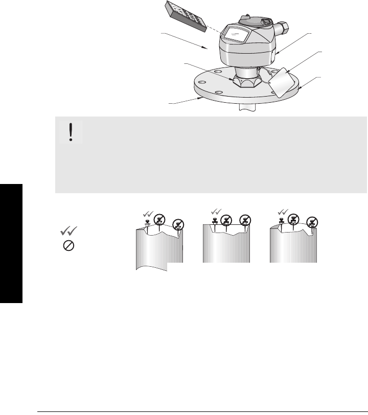
Mounting location
Recommendations:
• Maintain ambient temperature within –40 to +80 °C (–40 to +176 °F).
• Provide easy access for viewing the display and programming via the hand
programmer.
• Provide an environment suitable to the housing rating and materials of construction.
• Use a sunshield if the instrument will be exposed to direct sunlight (even though the
LCD has UV protection).
Precautions:
• Avoid interference to the emission cone from obstructions or from the fill path.
• Avoid central locations on vessels.
WARNING: For vessels with conical or parabolic tops, avoid
mounting the instrument at the centre. (The concavity of the top can
focus echoes into the centre, giving false readings.)
Note: Under certain circumstances, it may be acceptable to mount SITRANS LR250 at
the centre of a flat-topped tank: please discuss this with your Siemens Milltronics
representative.
process temperature
–40 to +150 °C (–40 to +302 °F)
ambient temperature
(surrounding enclosure volume)
–40 °C to 80 °C (–40 °F to 176 °F)
hand programmer
nameplate
process
device tag
customer-
supplied
flange
Coni
Fl at
Flat Parabolic Conical
preferred
undesirable
GRAPHIC TO BE UPDATED
7ML19985JE01 SITRANS LR250 (HART) – INSTRUCTION MANUAL Page 13
mmmmm
Installation
Keep the emission cone free of interference:
• Make allowance for the emission cone spreading (see table showing
beam width
on page 21).
• Locate the antenna away from the side wall, to avoid interference from indirect
echoes.
• Avoid interference from objects such as ladders or pipes, which can cause false
echoes.
• Make sure the emission cone does not intersect the fill path:
allowance for beam width
beam
width
Notes:
• beam width (defined at –3dB
boundary) depends on horn size:
see table showing
beam width
on page 21
• For more detail on false echoes,
see
Appendix F: Technical
Reference
on page 102.
GRAPHIC TO BE UPDATED
Page 14 SITRANS LR250 (HART) – INSTRUCTION MANUAL 7ML19985JE01
mmmmm
Installation
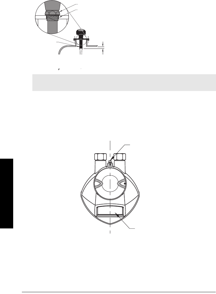
Location on a nozzle
On a nozzle, the horn should protrude a minimum or 100 mm (4") to avoid interference.
A manhole cover is typically a covered nozzle with a diameter 610 mm (24”) or greater. To
provide optimum signal conditions on a manhole cover, locate the horn off-center,
typically 100 mm (4") from the side.
Polarization reference point
For best results on a tank with obstructions, or a stillpipe with openings, orient the front
or back of the device toward the obstructions (see
Mounting: Stillpipe or Bypass
(Sidepipe)
on page 117 for an illustration.)
Note: For details on other applications, see
Appendix G: Special Applications
on
page 109.
10 mm
(0.4")
retaining collar
threaded connection
shield
GRAPHIC TO BE UPDATEDGRAPHIC TO BE UPDATED
polarization
reference point
display
7ML19985JE01 SITRANS LR250 (HART) – INSTRUCTION MANUAL Page 15
mmmmm
Installation
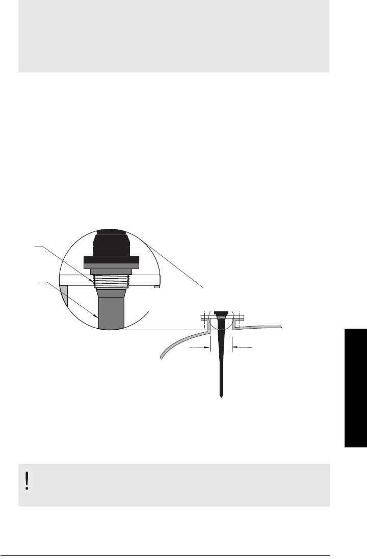
Mounting Instructions
Mounting: Threaded Version
1. Before inserting SITRANS LR250 into its mounting connection, check to ensure the
threads are matching, to avoid damaging them.
2. Simply screw SITRANS LR250 into the process connection, and hand tighten, or use
a wrench. For pressure applications, it will be necessary to use PTFE tape (or other
appropriate thread sealing compound) and tighten the process connection beyond
hand tight.
You can use 1.5” or 2” threaded process connections. There are three thread types: NPT,
BSP, and G.
A torque of 40 N-m (30 ft.lbs) is recommended
3. If you want to rotate the enclosure, use a 2 mm Allen key to loosen the set-screws
that secure the locking ring.
4. Once the enclosure is in a suitable position, tighten the set-screws. .
Notes:
• The device can be rotated past 360° without damage. When mounting, rotate the
head so the polarization dot faces the closest wall. In stilling well applications, line
up the polarization dot with the vent hole.
• Do not rotate the enclosure after programming and vessel calibration, otherwise an
error may occur, caused by a polarity shift of the transmit pulse.
WARNING: For pressure applications, it will be necessary to use
PTFE tape or other appropriate thread sealing compound, and to
tighten the process connection beyond hand-tight.
min. I.D. 100 mm (4")
Max. nozzle height 100 mm (4")
316 S.S.
PTFE
GRAPHIC TO BE UPDATED
Page 16 SITRANS LR250 (HART) – INSTRUCTION MANUAL 7ML19985JE01
mmmmm
Installation
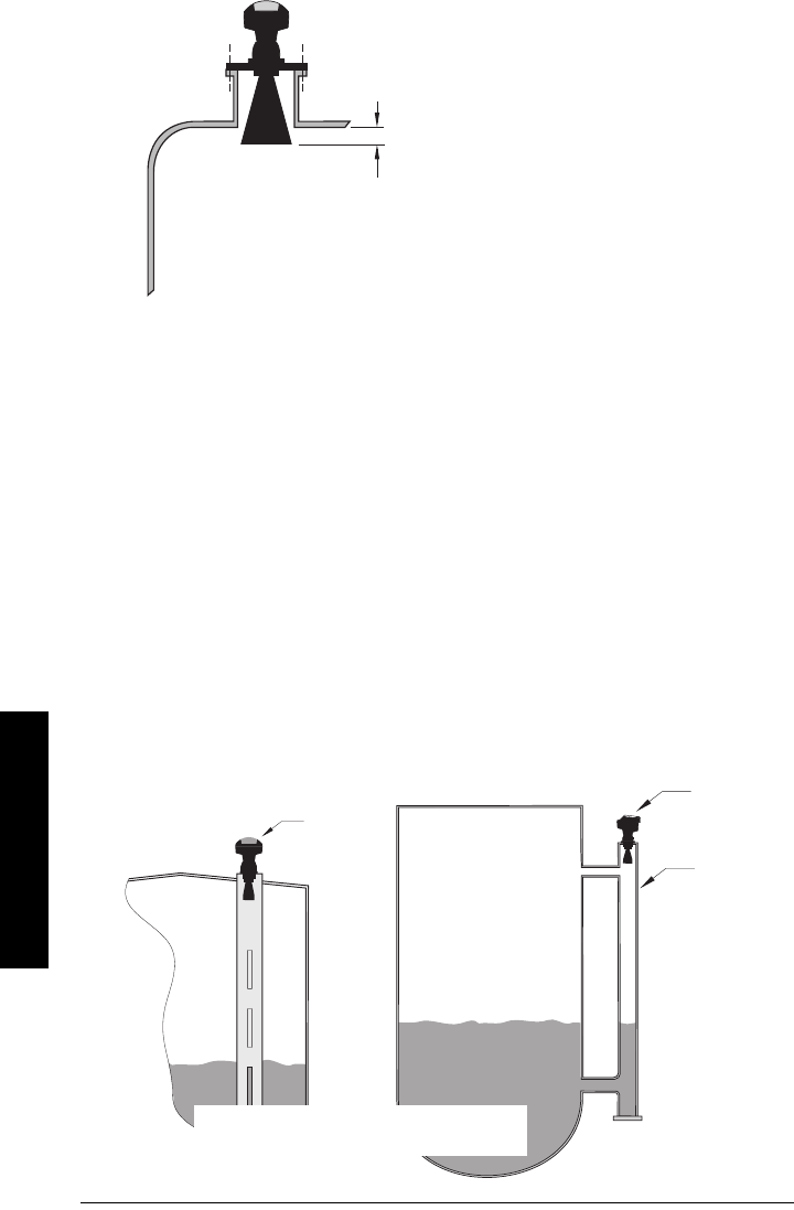
Horn Location on Nozzles
Mounting: Stillpipe or Bypass (Sidepipe)
This mounting arrangement is an alternative to the waveguide antenna option. It is used
for products with an εr less than 3 or for extremely turbulent or vortex conditions. It can
also be used to provide optimum signal conditions on foaming materials.
Pipe requirements
Diameter
Suitable pipe diameters are 50 mm (2”) to 100 mm (4”).
Smoothness
One continuous length of metallic pipe is preferred, without joints. If joints are
unavoidable, you must machine them to close tolerances (± 0.25 mm [± 0.010”]) and weld
a connecting sleeve on the outside.
10 mm (0.4")
GRAPHIC TO BE UPDATED
The end of the horn should protrude a
minimum of 10 mm (0.4”) to avoid inter-
ference with the nozzle
optimum
diameter
80 mm (3”)
align display
window with
vents
align
display
window
with
stillpipe
slots
Mounting on a bypass
Mounting on a stillpipe
GRAPHIC TO BE UPDATED

7ML19985JE01 SITRANS LR250 (HART) – INSTRUCTION MANUAL Page 17
mmmmm
Installation
See
Propagation Factor
on page 66 for the related propagation factor.
Ensure there is a vent at the upper end of the side pipe to equalize pressure and keep the
liquid-level in the pipe constant with the liquid-level in the vessel.
Mounting: Horn with Extension
Use this combination if the nozzle is long and
the diameter is small.
A 100 mm (4") horn extension is available.
GRAPHIC TO BE UPDATED
Page 18 SITRANS LR250 (HART) – INSTRUCTION MANUAL 7ML19985JE01
mmmmm
Installation
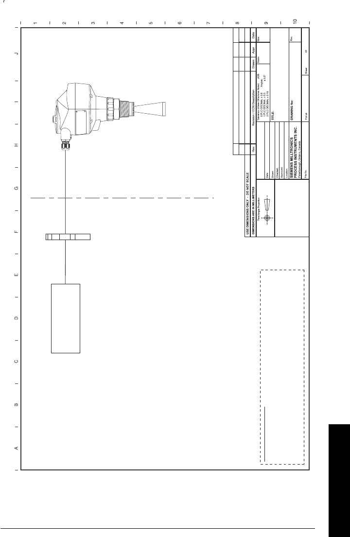
SITRANS LR250 Dimensions
Threaded Horn Antenna1
Notes:
• Process temperature and pressure capabilities are dependent upon information on
the process device tag. Reference drawing listed on the tag is available on our
website. Go to the product page for SITRANS LR250 at: xxxxxxx.
• Signal amplitude increases with horn diameter, so use the largest practical size.
• Optional waveguide extensions and/or purging1 system can be installed between
the flange and the antenna.
1. An optional purging system provides an inlet on the flange where cooling air or cleaning fluid
may be supplied. The air or liquid passes through the flange and exits the inside of the horn to
clean the antenna system.
ref. point
threaded cover
enclosure/
electronics
????
shield length (internal)
standard: 100 mm (4")
optional: 250 mm (10")
std. 296 mm (11.7") min.
option 446 mm (17.6") max.
158 mm
(6.2")
154 mm
(6.1") 185 mm
(7.3")
mounting thread
1/2" NPT cable entry
(or alternatively, M20 cable gland)
process device
tag
retaining
collar
109 mm
(4.3")
121 mm
(4.8")
50 mm
(2.0")
std. 575 mm (22.6") min.
option 725 mm (28.5") max.
23 mm (0.9")
GRAPHIC TO BE UPDATED

7ML19985JE01 SITRANS LR250 (HART) – INSTRUCTION MANUAL Page 19
mmmmm
Installation
Dimensions: Horn with extensions
Page 20 SITRANS LR250 (HART) – INSTRUCTION MANUAL 7ML19985JE01
mmmmm
Installation
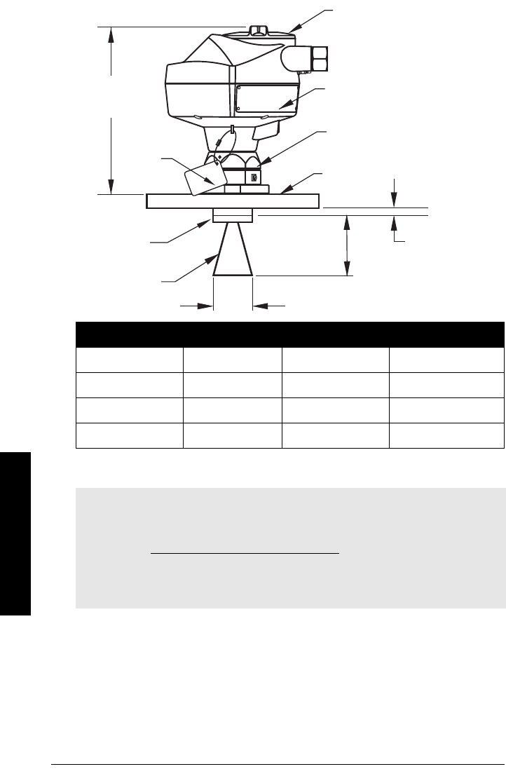
Dimensions: Flanged Horn
Nominal Horn Size Horn O.D. Horn Height beam width1
1. – 3dB in E-plane.
37.5 mm (1.5") 40.0 mm (1.57”) 100 mm (3.93") 19 degrees
50 mm (2”) 47.8 mm (1.88”) 96 mm (3.78”) 15 degrees
80 mm (3”) 74.8 mm (2.94”) 164 mm (6.46”) 10 degrees
100 mm (4”) 94.8 mm (3.73”) 214 mm (8.43”) 8 degrees
Notes:
• Process temperature and pressure capabilities are dependent upon information on
the process device tag. Reference drawing listed on the tag is available on our
website at www.siemens.com/processautomation, on the product page for
SITRANS LR250, under Process Connection Specifications.
• Signal amplitude increases with horn diameter, so use the largest practical size.
• Optional extensions can be installed between the flange and the antenna.
Ø 80 mm
(3")
enclosure/electronics
name-plate
flange
horn
reference
point
retaining collar
process
device
tag
187 mm (7.4")
GRAPHIC TO BE UPDATED
7 mm
(0.27")
horn
height
horn O.D.
7ML19985JE01 SITRANS LR250 (HART) – INSTRUCTION MANUAL Page 21
mmmmm
Installation
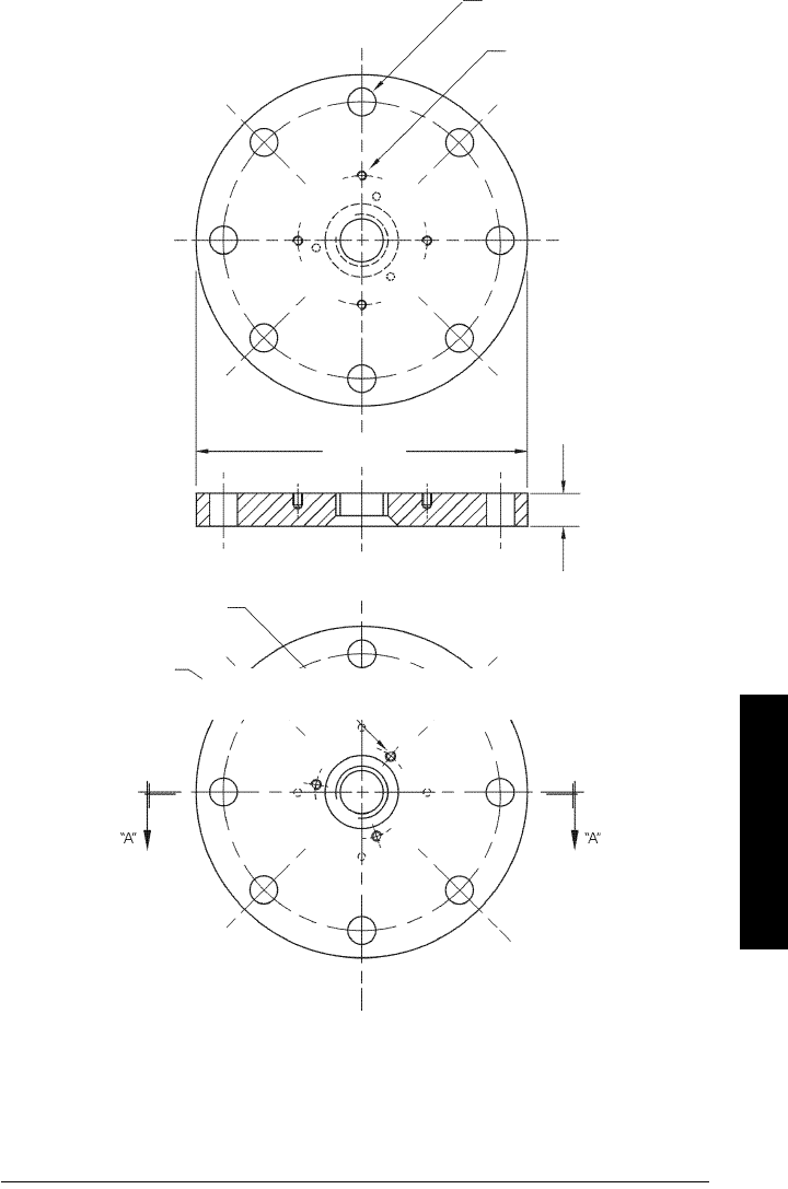
Dimensions: Flanges
See chart on page 23 for further details on flange sizes.
process side
20 mm (0.8”), nominal
enclosure
mounting holes
(threaded)
bolt hole Ø
bolt hole
circle Ø
flange O.D.
horn/waveguide
mounting holes
(threaded)
GRAPHIC TO BE UPDATED

Page 22 SITRANS LR250 (HART) – INSTRUCTION MANUAL 7ML19985JE01
mmmmm
Installation
Pipe size Flange Size Flange O.D. Bolt Hole
Circle Ø Bolt Hole Ø Number
of Bolts
2” ANSI 150# 6.0” 4.75” 0.7” 4
3” ANSI 150# 7.5” 6.0” 0.75” 4
4” ANSI 150# 9.0” 7.50” 0.75” 8
2” ANSI 300#** 6.50” 5.00” 0.75” 4
3” ANSI 300# 8.25” 6.62” 0.88” 8
4” ANSI 300# 10.00” 7.88” 0.88” 8
50 mm DIN PN 16 165 mm 125 mm 18 mm 4
80 mm DIN PN 16 200 mm 160 mm 18 mm 8
100 mm DIN PN 16 220 mm 180 mm 18 mm 8
50 mm DIN PN 40 165 mm 125 mm 18 mm 4
80 mm DIN PN 40 200 mm 160 mm 18 mm 8
100 mm DIN PN 40 235 mm 190 mm 22 mm 8
50 mm JIS 10K 155 mm 120 mm 19 mm 4
80 mm JIS 10K 185 mm 150 mm 19 mm 8
100 mm JIS 10K 210 mm 175 mm 19 mm 8

7ML19985JE01 SITRANS LR250 (HART) – INSTRUCTION MANUAL Page 23
mmmmm
Installation
Page 24 SITRANS LR250 (HART) – INSTRUCTION MANUAL 7ML19985JE01
mmmmm
Wiring
Wiring
Power
Connecting SITRANS LR250
1
WARNINGS:
The DC input terminals shall be supplied from a source providing
electrical isolation between the input and output, in order to meet
the applicable safety requirements of IEC 61010-1.
All field wiring must have insulation suitable for rated voltages.
WARNINGS:
• Check the nameplate on your instrument, to verify the approval rating.
• Use appropriate conduit seals to maintain IP or NEMA rating.
•Read
Instructions specific to hazardous area installations
on page 31.
Notes:
• Use twisted pair cable: AWG 22 to 14 (0.34 mm2 to 2.5 mm2).
• Separate cables and conduits may be required to conform to standard
instrumentation wiring practices or electrical codes.
1. Depending on the approval rating, glands and plugs may be supplied with your
instrument.
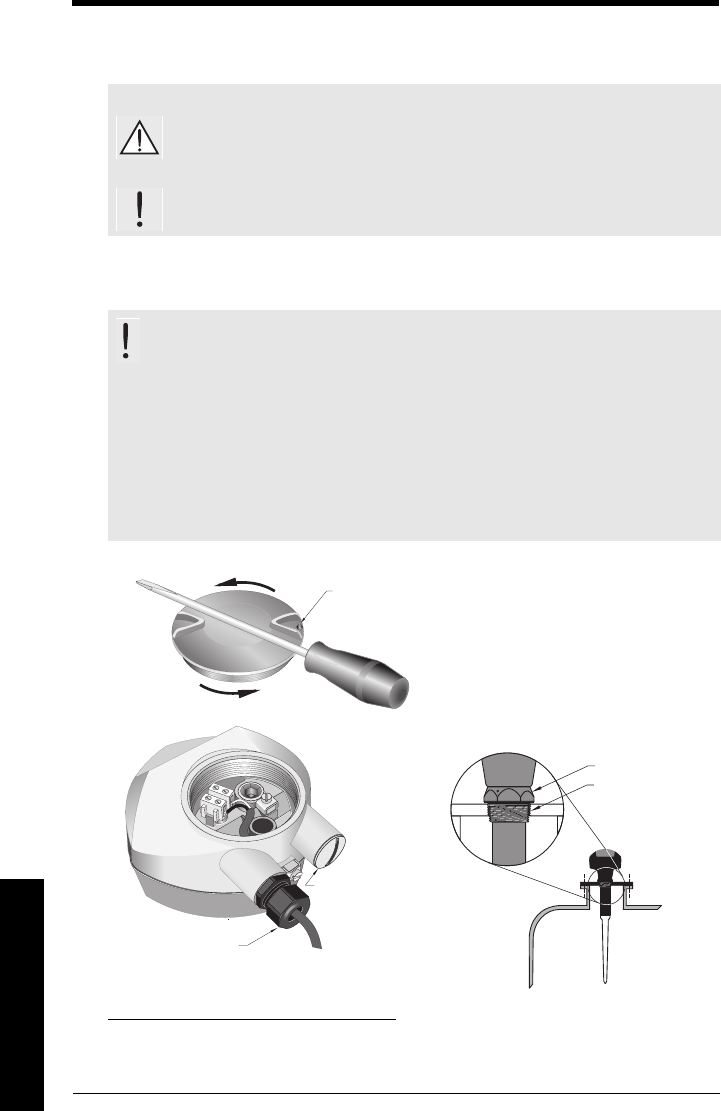
Use a 2 mm Allen key to loosen the lid-lock set screw.
Unscrew the cover for access to the terminals. Use a
screwdriver for added leverage, if necessary.
cable gland1
(or NPT cable entry)
If you want to rotate the enclosure, use the 2 mm
Allen key to loosen the locking ring.
locking ring
threaded connection
plug1
7ML19985JE01 SITRANS LR250 (HART) – INSTRUCTION MANUAL Page 25
mmmmm
Wiring
1. Strip the cable jacket for approximately 70 mm
(2.75") from the end of the cable, and thread
the wires through the gland1.
2. Connect the wires to the terminals as shown:
the polarity is identified on the terminal block.
3. Ground the instrument according to local
regulations.
4. Tighten the gland to form a good seal.
Wiring setups for hazardous
area installations
There are five wiring options for hazardous area installations. In all cases, check the
nameplate on your instrument, and confirm the approval rating.
1. Intrinsically Safe wiring
1. If cable is routed through conduit, use only approved suitable-size hubs for
waterproof applications.
Approval Rating Valid for:
ATEX II 1 G, EEx ia IIC T4
ATEX II 1 D, EEx tD A20 IP67 T90 °C Europe
IECEx SIR 05.0031X, Ex ia IIC T4, Ex tD A20 IP67 T90 °C International
FM/CSA:
Class I, Div. 1, Groups A, B, C, D
Class II, Div. 1, Groups E, F, G
Class III
US/Canada
cable shield
(if used)
WARNING: Possible Static Hazard, Do Not Rub Or Clean On Site.
Exia per drawing: 23650653
Class I, Div1,Group A,B,C,D
Class III
Class II, Div1,Group G
CANADA: 267P - LR 250
HART
R
FCC ID: NJA - LR 250
Pmax = 0.8 W
Ci=15nF
Temp.Code:T4
Vmax = 30V
Li=0.1mH
Imax = 120mA
SITRANS LR 250
Made in Canada
Siemens Milltronics Process Instruments Inc., Peterborough
7ML1234-56789-0ABC-D
Encl.: NEMA / TYPE 4X, 6, IP67, IP68
Amb.Temp.: – 40 °C to 80 °C
Power Rating: 24V Max., 4 - 20mA
Nom., 30 V
Serial No: GYZ / S1034567
WARNING: Possible Static Hazard, Do Not Rub Or Clean On Site.
Ii = 120 mA
Ui = 30V
Li = 0.1mH
Pi = 0.8W
Ci = 15nF
HART
II 1 D IP68 Txx
II 1 G EEx ia IIC T4
03ATEX2142X
IECEx SIR 05.0031X
Ex ia IIC T4
SIRA
SITRANS LR 250
Made in Canada
Siemens Milltronics Process Instruments Inc., Peterborough
7ML1234-56789-0ABC-D
Encl.: NEMA / TYPE 4X, 6, IP67, IP68
Amb.Temp.: – 40 °C to 80 °C
Power Rating: 24V Max., 4 - 20mA
Nom., 30 V
Serial No: GYZ / S1034567
Page 26 SITRANS LR250 (HART) – INSTRUCTION MANUAL 7ML19985JE01
mmmmm
Wiring
• For power demands see
Curve 1 (General Purpose, Intrinsically Safe, Non-
incendive)
on page 111.
• For wiring requirements:
Europe/International: Follow local regulations.
US/Canada: Download
Wiring drawing (Intrinsically Safe: FM/CSA)
drawing number 23650563 from the product page of our
website at: ##### or see page 29.
• Approved dust-tight and water-tight conduit seals are required for outdoor
NEMA 4X / type 4X / NEMA 6, IP67, IP68 locations.
• Recommended intrinsically safe barriers are listed on page 26.
• Refer to
Instructions specific to hazardous area installations
on page 31.
PLC Input Modules
Note: Selecting a suitable PLC input module, power supply, or barrier requires
knowledge about Intrinsic Safety and the application. It is the responsibility of the
installer to ensure that the intrinsically safe installation complies with both the
apparatus approval requirements and the relevant national code of practice.
Notes:
• The following list is not exhaustive: there are many IS power supplies and barriers
on the market which will work with the LR 250.
• The PLC input modules and barriers listed below have all been tested and are
functionally compatible with the LR 250.
Manufacturer Part Number
Siemens SM331 PCS7 HART Input Module
Stahl Type 9461 Analog Input 2-Wire HART Module (for IS1)
Siemens 4 x Analog Input I 2-Wire HART Module (for ET200iSP)
Bartec Profibus Interface - 8 x 4...20mA Input Module
ABB AI930N 4 x Analog Input HART Module (for S900)
Siemens SM331 2 x Analog Input HART Module (for ET200M)
Siemens SM331 4 x Analog Input Module (for ET200M)

7ML19985JE01 SITRANS LR250 (HART) – INSTRUCTION MANUAL Page 27
mmmmm
Wiring
Passive Shunt Diode Barriers
How to select a passive barrier for SITRANS LR 250
1. Make sure that the barrier safety description is suitable for the LR 250 Intrinsically
Safe (IS) input parameters.
2. Determine the maximum end-to-end resistance of the barrier (Re-e) from the data
sheet.
3. Determine other loop resistance (Rloop): for example, sense resistance, displays,
and/or PLC inputs.
4. Calculate Rworking = Re-e + Rloop.
5. Determine any non-linear voltage drops due to the barrier (Vbarrier) from the barrier
data sheet (for example, voltage drops due to diodes).
6. Calculate Vworking = Vsupply – Vbarrier.
Using Vworking and Rworking, confirm that operation is within the shaded area of
the graph
Loop Voltage versus Loop Resistance
on page 111
Active barriers (repeating barriers)
Note: A well regulated supply voltage is required.
Manufacturer Part Number
MTL 787SP+ (Dual Channel)
MTL 7787P+ (Dual Channel)
Stahl 9001/01-280-100-10 (Single Channel)
Stahl 9002/01-280-110-10 (Dual Channel)
Manufacturer Part Number
MTL 706
MTL 7206
Stahl 9001/51-280-110-14
Pepperl+Fuchs KSD2-CI-S-Ex
Pepperl+Fuchs KFD2-STC3-Ex1
MTL E02009 - verify
MTL E02010

Page 28 SITRANS LR250 (HART) – INSTRUCTION MANUAL 7ML19985JE01
mmmmm
Wiring
2. Non-incendive wiring (only for USA/Canada)
• For power demands see
Curve 1 (General Purpose, Intrinsically Safe, Non-
incendive)
on page 111.
• For wiring requirements download
Wiring drawing (Non-incendive: FM/CSA)
drawing number 23650637 from the product page of our website at: #####, or see
page 30.
Approval Rating Valid for:
FM/CSA:
Class I, Div. 2, Groups A, B, C, D T5 US/Canada
Class I, Div. 2,
Group A,B,C,D
Temp. Code: T5
This device complies with Part 15 of the FCC Rules.
Operation is subject to the following two conditions
1)This device may not cause harmful interference and
2)This device must accept any interference received,
including interference that may cause undesired operation
CANADA: 267P - LR 250
FCC ID: NJA - LR 250
26 Ghz HART
R
SITRANS LR 250
Made in Canada
Siemens Milltronics Process Instruments Inc., Peterborough
7ML1234-56789-0ABC-D
Encl.: NEMA / TYPE 4X, 6, IP67, IP68
Amb.Temp.: – 40 °C to 80 °C
Power Rating: 24V Max., 4 - 20mA
Nom., 30 V
Serial No: GYZ / S1034567
7ML19985JE01 SITRANS LR250 (HART) – INSTRUCTION MANUAL Page 29
mmmmm
Wiring
Wiring drawing (Intrinsically Safe: FM/CSA)
Product Group
FOR INTERNAL
USE ONLY
2365065300
S. NGUYEN
PETERBOROUGH
25 / JULY / 2005
RADAR
FOR APPROVAL
0
E. DE SIMONE
R. CLYSDALE
1:1 1
1
NTS
B
SITRANS LR 250, HART
INTRINSICALLY SAFE
CONNECTION DIAGRAM
23650653
0
RPC SN
JULY
25/2005
NOTES:
1. ANY CSA / FM INTRINSICALLY SAFE BARRIER / POWER SUPPLY, WITH ITS OUTPUT
VOLTAGE (Uo) NOT EXCEEDING 30 V AND ITS OUTPUT CURRENT (Io) LIMITED BY
LOAD RESISTANCE (Ro); SUCH THAT Io = Uo / Ro, DOES NOT EXCEED 120 mA
2. APPROVED DUST-TIGHT AND WATER-TIGHT CONDUIT SEALS ARE REQUIRED
FOR CLASS II, DIV.1, Gr. E, F, G AND OUTDOOR NEMA 4X / TYPE 4X LOCATIONS
3. THE MAXIMUM VOLTAGE OF THE NON-INTRINSICALLY SAFE APPARATUS
MUST NOT EXCEED 250 V rms.
4. UNDER THE ENTITY EVALUATION CONCEPT, THE LR 200 HAS THE
FOLLOWING:
Ui = 30 VOLTS D.C. Ii = 120 mA Pi = 0.8W
Ci=15nF Li=0.1mH
5. SUBSTITUTION OF COMPONENTS MAY IMPAIR INTRINSIC SAFETY.
6. INSTALL PER NEC / CEC
7. USE SUPPLY WIRES RATED FOR 10 ° ABOVE.
8. EXTERNAL BONDING HUBS ARE REQUIRED WHEN BOTH CONDUIT ENTRIES ARE USED.
THE ENTITY EVALUATION CONCEPT IS A METHOD USED TO DETERMINE
ACCEPTABLE COMBINATIONS OF INTRINSICALLY SAFE APPARATUS AND
CONNECTED ASSOCIATED APPARATUS THAT HAVE NOT BEEN
INVESTIGATED IN SUCH COMBINATION.
HAZARDOUS AREA
NON-HAZARDOUS AREA
SAFE AREA APPARATUS
INTRINSICALLY SAFE
(SEE NOTE 1)
Load
4–20mA
ENTITY CONCEPT DEFINITION: THE ENTITY CONCEPT ALLOWS THE INTERCONNECTIONS OF INTRINSICALLY
SAFE APPARATUS TO ASSOCIATED APPARATUS NOT SPECIFICALLY EXAMINED IN SUCH COMBINATIONS.
THE CRITERIA FOR INTERCONNECTION IS THAT THE VOLTAGE AND CURRENT WITH INTRINSICALLY SAFE
APPARATUS CAN RECEIVE AND REMAIN INTRINSICALLY SAFE, CONSIDERING FAULTS, MUST BE EQUAL OR
GREATER THAN THE VOLTAGE (Uo) AND CURRENT (Io) LEVELS WHICH CAN BE DELIVERED BY
THE ASSOCIATED APPARATUS, CONSIDERING FAULTS AND APPLICABLE FACTORS. IN ADDITION, THE MAX.
UNPROTECTED CAPACITANCE (Ci) AND INDUCTANCE (Li) OF THE INTRINSICALLY SAFE APPARATUS, INCL.
INTERCONNECTING WIRING, MUST BE EQUAL OR LESS THAN THE CAPACITANCE AND INDUCTANCE WHICH
CAN BE SAFELY CONNECTED TO THE ASSOCIATED APPARATUS.
TO BE REPLACED WITH FLIP-OUT PAGE 23650653
Page 30 SITRANS LR250 (HART) – INSTRUCTION MANUAL 7ML19985JE01
mmmmm
Wiring
Wiring drawing (Non-incendive: FM/CSA)
TO BE REPLACED WITH FLIP-OUT PAGE 23650637
Product Group
FOR INTERNAL
USE ONLY
2365063700
S. NGUYEN
PETERBOROUGH
20 / JULY / 2005
RADAR
FOR CONSTRUCTION
0
T. LITTLE
R. CLYSDALE
1:1 11
NTS
A
SITRANS LR 250
CLASS I, Div. 2
CONNECTION DRAWING
23650637 0
RPC SN JULY
20/2005
NON-HAZARDOUS LOCATION
(SAFE)
HAZARDOUS LOCATION
CLASS I, DIV.2, GROUPS A, B, C, D
24 V
POWER
SUPPLY
SITRANS LR 250
1/2 “ NPT
NOTES:
METAL CONDUIT

7ML19985JE01 SITRANS LR250 (HART) – INSTRUCTION MANUAL Page 31
mmmmm
Wiring
Instructions specific to hazardous area
installations
(Reference European ATEX Directive 94/9/EC,
Annex II, 1/0/6)
The following instructions apply to equipment covered by certificate number SIRA
03ATEX2142X:
1. For use and assembly, refer to the main instructions.
2. The equipment is certified for use as Category 1GD equipment.
3. The equipment may be used with flammable gases and vapors with apparatus group
IIC and temperature class T4.
4. The equipment is certified for use in an ambient temperature range of –40 °C to
80 °C.
5. The equipment has not been assessed as a safety related device (as referred to by
Directive 94/9/EC Annex II, clause 1.5).
6. Installation and inspection of this equipment shall be carried out by suitably trained
personnel in accordance with the applicable code of practice (EN 60079-14 and
EN 60079-17 in Europe).
7. Repair of this equipment shall be carried out by suitably trained personnel in
accordance with the applicable code of practice (e.g. EN 60079-19 within Europe).
8. Components to be incorporated into or used as replacements in the equipment shall
be fitted by suitably trained personnel in accordance with the manufacturer’s
documentation.
9. The ‘X’ suffix to the certificate number relates to the following special conditions for
safe use:
a. Parts of the enclosure may be non-conducting and may generate an ignition-
capable level of electrostatic charge under certain extreme conditions. The user
should ensure that the equipment is not installed in a location where it may be
subjected to external influences which might cause a build-up of electrostatic
charge on non-conducting surfaces.
b. As either Aluminum, Magnesium, Titanium or Zirconium
may be used at the
accessible surface of the equipment, in the event of rare incidents, ignition
sources due to impact and friction sparks could occur. This shall be considered
when the SITRANS LR 250 is being installed in locations that specifically require
group II, category 1G equipment.
(continued on next page)

Page 32 SITRANS LR250 (HART) – INSTRUCTION MANUAL 7ML19985JE01
mmmmm
Wiring
10. The certification of this equipment relies upon the following materials used in its
construction:
Aluminum alloy ANSI ref. A380.0 (aluminum enclosure option)
Valox 365 (injection moulded plastic enclosure option)
Ultem 1010 (window on plastic enclosure option)
Stycast 2651-40FR encapsulant, catalyst II
The detailed composition of Aluminum A380.0 as used in the metal enclosure
(threaded lid option only) is as follows:
Si – 8.5%, Fe – 1.3%, Cu – 3.5%, Mn – 0.5%, Mg – 0.1%, Ni – 0.1%, Zn – 3%,
Sn – 0.35%, others – 0.5%, Al - balance
In applications requiring category 1G or 1/2G equipment, SITRANS LR250 must not
be exposed to materials to which the wetted parts1 of the instrument are not
resistant.
11. Equipment Marking
The equipment marking contains at least the information on the product nameplate.
1. Any surface (probe, o-rings, gaskets) exposed to the process fluid or gas.
LR 250 Version Approval Rating Nameplate
Intrinsically Safe
ATEX II 1 G, EEx ia IIC T4
ATEX II 1 D, EEx tD A20 IP67 T90 °C
IECEx SIR 05.0031X, Ex ia IIC, Ex tD
A20 IP67 T90 °C T4
FM/CSA:
Class I, Div. 1, Groups A, B, C, D
Class II, Div. 1, Groups E, F, G
Class III T4
See page 25
Non-incendive FM/CSA:
Class I, Div. 2, Groups A, B, C, D T5 See page 28
7ML19985JE01 SITRANS LR250 (HART) – INSTRUCTION MANUAL Page 33
mmmmm
Quick Start
Quick Start
A Quick Start wizard groups together all the settings you need for a simple application.
There are two ways to access the wizard:
•
Quick Start Wizard via the handheld programmer
on page 35
•
Quick Start Wizard via SIMATIC PDM
on page 38
Activating SITRANS LR250
Power up the instrument. SITRANS LR250 automatically starts up in Measurement (RUN)
mode.
Measurement mode (RUN mode)
1
If more than one fault is present, the status indicator and text for each fault alternate at
2 second intervals. See
General Fault Codes
on page 79 for a list.
Note: SITRANS LR250 supports SIMATIC PDM version 6.0 with SP2.
Note: Keep infrared devices such as laptops, cell phones, and PDAs, away from
SITRANS LR250 to prevent inadvertent operation.
1. In response to a key press request. For details, see
Navigating in PROGRAM mode
on page 73.
LEVEL
[M]
21.40 °C
DATA EXCH.
18.91
134
2
65
Normal operation
7
8
1 – toggle indicator for linear units
or %
2 – selected operation: level, space,
or distance
3 – measured value (level, space or
distance)
4 – units
5 – bar graph indicates level
6 – secondary region indicates
electronics temperature, echo
confidence, loop current, or
distance1
7 – text area displays status
messages
8 – device status indicator
S: 0 LOE S: 53 CONFIG LO
Fault present
Page 34 SITRANS LR250 (HART) – INSTRUCTION MANUAL 7ML1998JE01
mmmmm
Quick Start
Programming SITRANS LR250
• For detailed information see
Appendix F: Local Operation Interface
on page 94. or
Parameter Reference
on page 41.
• To program SITRANS LR250 using the Quick Start wizard, follow the instructions
below.
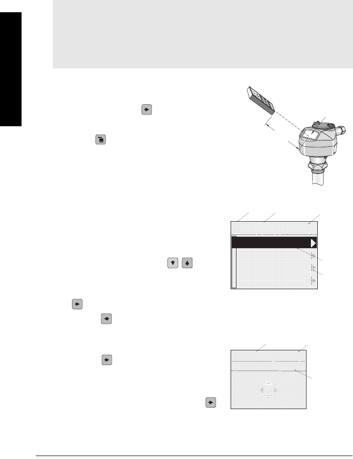
The handheld programmer and PROGRAM mode display
• Point the programmer at the display (from a
maximum distance of 600 mm [2 ft.]), then
press Right ARROW to activate
PROGRAM mode and open menu level 1.
(Mode opens the menu level last
displayed in PROGRAM mode within the last
10 minutes, unless power has been cycled
since then. Then menu level 1 will be
displayed.)
•Use ARROW keys to navigate to a menu item.
The current selection is highlighted and the
level number is shown. A pointer is visible if a
lower level exists.
• Press Down or Up ARROWS to scroll
to the next selection.
• At higher menu levels press Right ARROW
to open the next menu level or Left
ARROW to back up one level.
• At the lowest menu level, parameters are
listed, and no pointers are visible. Press Right
ARROW to open parameter view.
• In parameter view, the parameter name and
number are displayed, as well as current
selection or value. Press Right ARROW
to open Edit mode.
Notes:
• See
Appendix F: Local Operation Interface
on page 94 for more detailed information
on the programmer and the LCD display.
• SITRANS LR250 automatically returns to Measurement mode after a period of
inactivity in PROGRAM mode (between 15 seconds and two minutes, depending on
the menu level).
INPUT 2.2.1
SENSOR CALIB
VOL CONVERSION
VOLUME BREAKPT
ECHO PROC.
SENSOR CALIB
APPLICATIO..
2.2.1.2
LIQUID
PREVIOUS
NEXT
BACK EDIT
handheld programmer
(ordered separately)
Max. 600 mm
(2 ft)
display
menu
pointer
parameter
number
parameter
selection
unlocked
icon
GRAPHIC TO
BE REVISED
current item
number
current
item
parameter name
7ML19985JE01 SITRANS LR250 (HART) – INSTRUCTION MANUAL Page 35
mmmmm
Quick Start
• The current selection is highlighted.
If required, scroll to a new selection or key in a new
value and press Right ARROW to accept it. The LCD
displays the new value.
• Press Mode to return to Measurement mode.
Quick Start Wizard via the handheld programmer
1. Quick Start
a. Point the programmer at the display (from a maximum distance of 600 mm [2 ft.]),
then press Right ARROW to activate PROGRAM mode and open menu level 1.
b. Press Right ARROW twice to navigate to menu item 1.1 and open parameter
view.
c. Press Right ARROW to open Edit mode or Down ARROW to accept default
values and move directly to the next item.
d. To change a setting, scroll to the desired item or key in a new value.
e. After modifying a value, press Right ARROW to accept it and press Down
ARROW to move to the next item.
f. Quick Start settings take effect only after you select Yes to Apply changes in step 1.7.
1.1. Application Type
1.2. Response Rate
Sets the reaction speed of the device to measurement changes in the target range.
Use a setting just faster than the maximum filling or emptying rate (whichever is
greater). Slower settings provide higher accuracy: faster settings allow for more
level fluctuation
Notes:
• The wizard is a complete package and the settings are inter-related.
• Because the settings are inter-related, the initial Quick Start parameter values are
not default values and do not necessarily reflect the current device configuration.
• Do not use the Quick Start wizard to modify individual parameters: see instead
Parameter Reference
on page 41.
Options
LIQUID
SOLID
LIQUID LOW DK (low dielectric liquid)
Options
SLOW 0.1 m/minute
MED 1.0 m/minute
FAST 10.0m/minute
APPLICATIO..
2.2.1.2
SOLID
LIQUID LOW DK
LIQUID
Page 36 SITRANS LR250 (HART) – INSTRUCTION MANUAL 7ML1998JE01
mmmmm
Quick Start
1.3. Sensor Units
Select the units for the Quick Start variables (high and low calibration point, and level,
distance, or space)
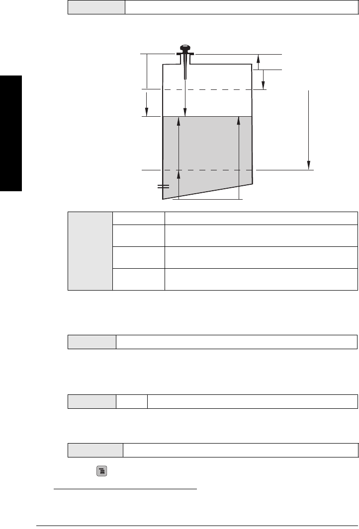
1.4. Operation
1
1.5. Low Calibration Point
Distance from Sensor Reference to Low Calibration Point: usually process empty
level. (See 1.4. Operation for an illustration.)
1.6. High Calibration Point
Distance from Sensor Reference to High Calibration Point: usually process full level.
(See 1.4. Operation for an illustration.)
1.7. Apply? (Apply changes)
In order to save the Quick Start settings it is necessary to select Yes to apply changes.
Press Mode to return to Measurement mode. SITRANS LR250 is now ready to operate.
Options M, CM, MM, FT, IN
Options
NO SERVICE
LEVEL Distance to material surface referenced from Low Calibration
Point (process empty level).
SPACE Distance to material surface referenced from High Calibration
Point (process full level).
DISTANCE Distance to material surface referenced from Sensor
Reference Point.
1. The point to which all of the above parameters are referenced. See
SITRANS LR 250
Dimensions
on page 14.
Values Range: 0.0000 to 20.000 m
Values Range 0.0000 to 20.000 m
Options YES, NO
high
calibration
point
low calibration point
level
space
distance
sensor reference
point1
Operation types
GRAPHIC TO
BE REVISED
7ML19985JE01 SITRANS LR250 (HART) – INSTRUCTION MANUAL Page 37
mmmmm
Quick Start
Level application example
Auto False Echo Suppression
If SITRANS LR250 displays a false high level, or the reading is fluctuating between the
correct level and a false high level, you can use the Auto False Echo Suppression
parameters to prevent false echo detection. See
2.2.5. TVT (Auto False Echo Suppression)
setup
on page 41 for instructions.
Quick Start Setting Description
APPLICATION LIQUID
RESPONSE RATE SLOW Response rate = 0.1 m/minute.
UNITS m
OPERATION LEVEL Material level referenced from Low Calibration Point.
LOW CALIBRATION POINT 15.5 Process empty level.
HIGH CALIBRATION POINT 1.0 Process full level.
APPLY? (CHANGES) YES Save new settings.
Sensor
Reference
Point
Level
Low
Calibration
Point
High
Calibration
Point 15.5 m
1.0 m
SITRANS LR250
The application is a vessel that
takes an average 3 hours to fill and
3 weeks to empty.
Fill rate = 0.09 m/minute (15.5 / 180).
Response rate has been set to
slow: 0.1 m/minute, or slightly faster
than the fill rate
GRAPHIC TO BE
REVISED
Page 38 SITRANS LR250 (HART) – INSTRUCTION MANUAL 7ML1998JE01
mmmmm
Quick Start
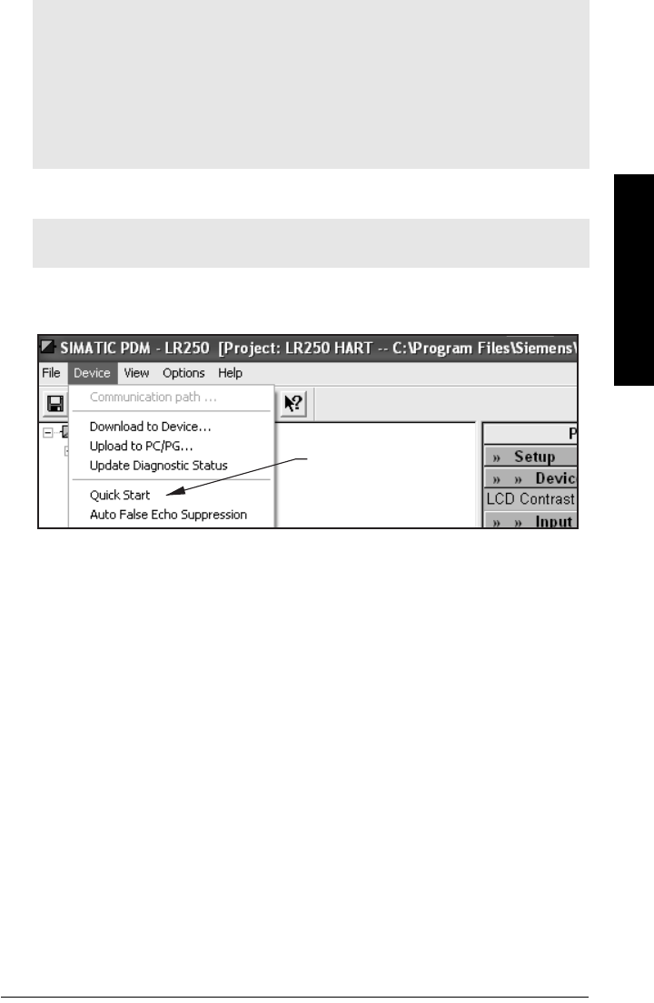
Quick Start Wizard via SIMATIC PDM
The graphical Quick Start Wizard groups together all the settings you need to make for a
simple application into 4 steps.
To use HART or PROFIBUS PA, you will need a PC configuration tool: we recommend
SIMATIC PDM.
Please consult the operating instructions or online help for details on using SIMATIC
PDM. (Application Guides for setting up Siemens HART and PROFIBUS PA instruments
with SIMATIC PDM are available on our website: www.siemens.com/
processautomation.)
Device Description (DD)
You will need the DD for SIMATIC PDM version 6.0 with SP2. You can locate the DD in
Device Catalog, under Sensors/Level/Echo/Siemens Milltronics/SITRANS LR250. If you do
not see SITRANS LR250 under Siemens Milltronics, you can download the DD from the
product page of our website at: https://pia.khe.siemens.com/index.asp?Nr=7427, under
Downloads.
Save the files to your computer, and extract the zipped file to an easily accessed location.
Launch SIMATIC PDM – Manager Device Catalog, browse to the unzipped DD file and
select it.
Configuring a new device
1. Set Address (default for PROFIBUS PA is 126; for HART is 0).
• Press Right ARROW to activate PROGRAM mode and open menu level 1.
• Press Down ARROW repeatedly to navigate to COMMUNICATION (menu
item 5).
• Press Right ARROW to display the parameter list.
• Scroll to DEVICE ADDRESS and press Right ARROW to open parameter
view.
• If required, Press Right ARROW to open Edit mode. Key in a new value and
press Right ARROW to accept it. The LCD displays the new value in
parameter view.
• Press Mode to exit PROGRAM mode
2. You will need the most up-to-date Device Description (DD) for your instrument.
Launch SIMATIC PDM – Manager Device Catalog, browse to the unzipped DD file
and select it.
3. Launch SIMATIC Manager and create a new project for LR250. Application Guides
for setting up HART and PROFIBUS PA devices with SIMATIC PDM.can be
downloaded from the product page of our website at:
https://pia.khe.siemens.com/index.asp?Nr=7427
4. Open the menu Device – Reset and click on Factory Reset.
5. Upload parameters to the PC/PG.
6. Calibrate the device via the Quick Start Wizard.
7ML19985JE01 SITRANS LR250 (HART) – INSTRUCTION MANUAL Page 39
mmmmm
Quick Start
Quick Start Wizard steps
Quick Start steps
Launch SIMATIC Manager, create a new project, open the menu Device – Quick Start,
and follow steps 1 to 5.
Notes:
• The Quick Start settings are not independent parameters. The settings are inter-
related, and changes only apply when you click Transfer at the end of step 4.
• Do not use the Quick Start Wizard to modify individual parameters: see instead
Parameter Reference
on page 41.
• Click BACK to return and revise settings, or Cancel to exit the Quick Start.
• The layout of the dialog boxes shown may vary according to the resolution setting for
your computer monitor.
Note: The layout of the dialog boxes shown may vary according to the resolution
setting for your computer monitor.
Quick
Start
Page 40 SITRANS LR250 (HART) – INSTRUCTION MANUAL 7ML1998JE01
mmmmm
Quick Start
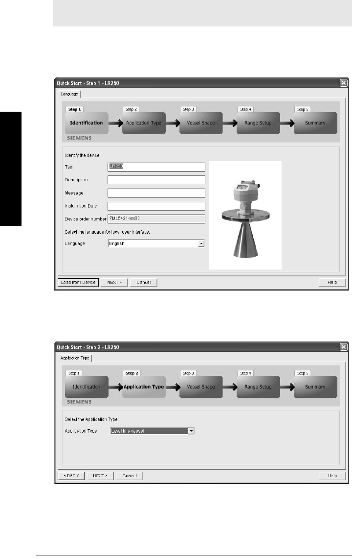
Step 1 – Identification
Click NEXT to accept the default values. (Description, Message, and Installation Date
fields can be left blank.)
Step 2 – Application
Select the application type, and click NEXT.
Note: At any stage after step 1, you can click BACK, to return and revise settings, or
Cancel to exit the Quick Start.
7ML19985JE01 SITRANS LR250 (HART) – INSTRUCTION MANUAL Page 41
mmmmm
Quick Start
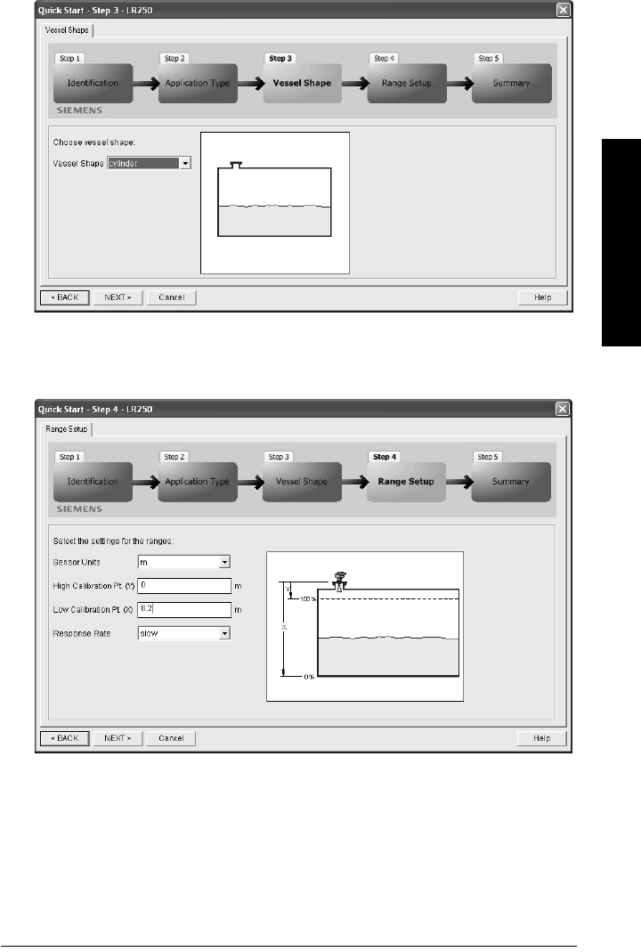
Step 3 – Vessel Shape
Select the vessel shape, and click NEXT.
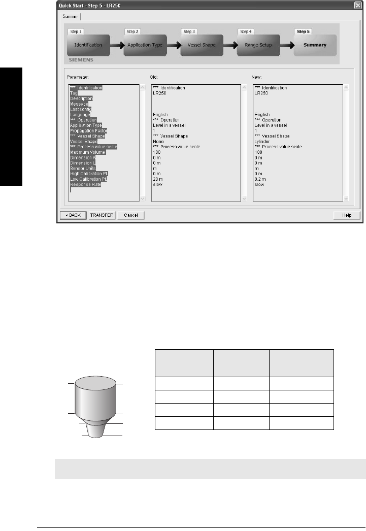
Step 4 – Range
Set the parameters, and click NEXT.
Page 42 SITRANS LR250 (HART) – INSTRUCTION MANUAL 7ML1998JE01
mmmmm
Quick Start
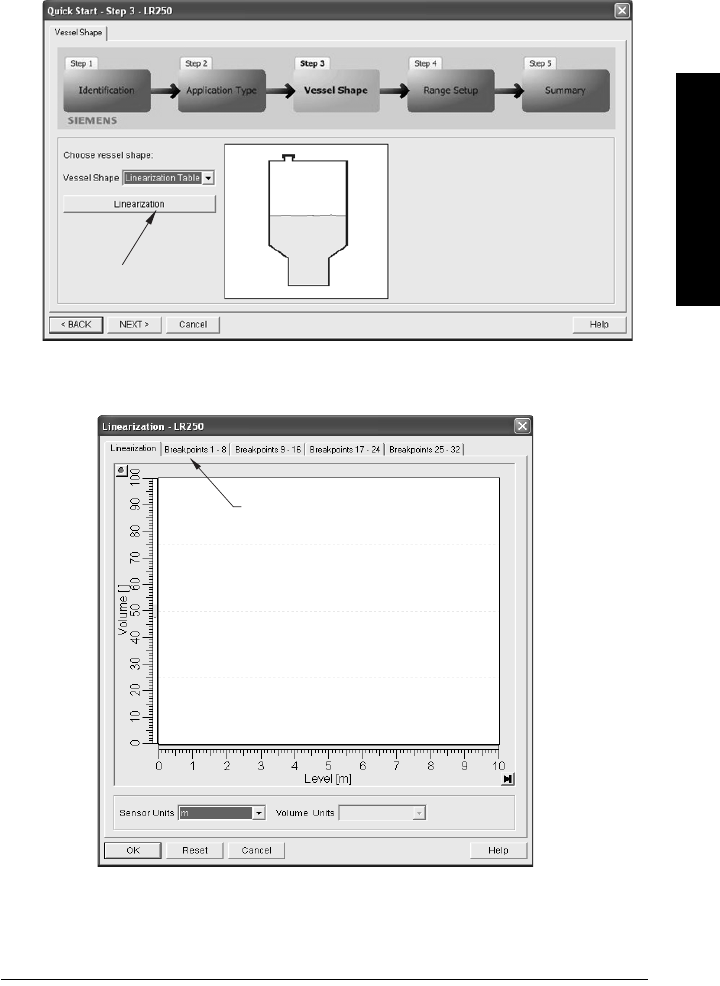
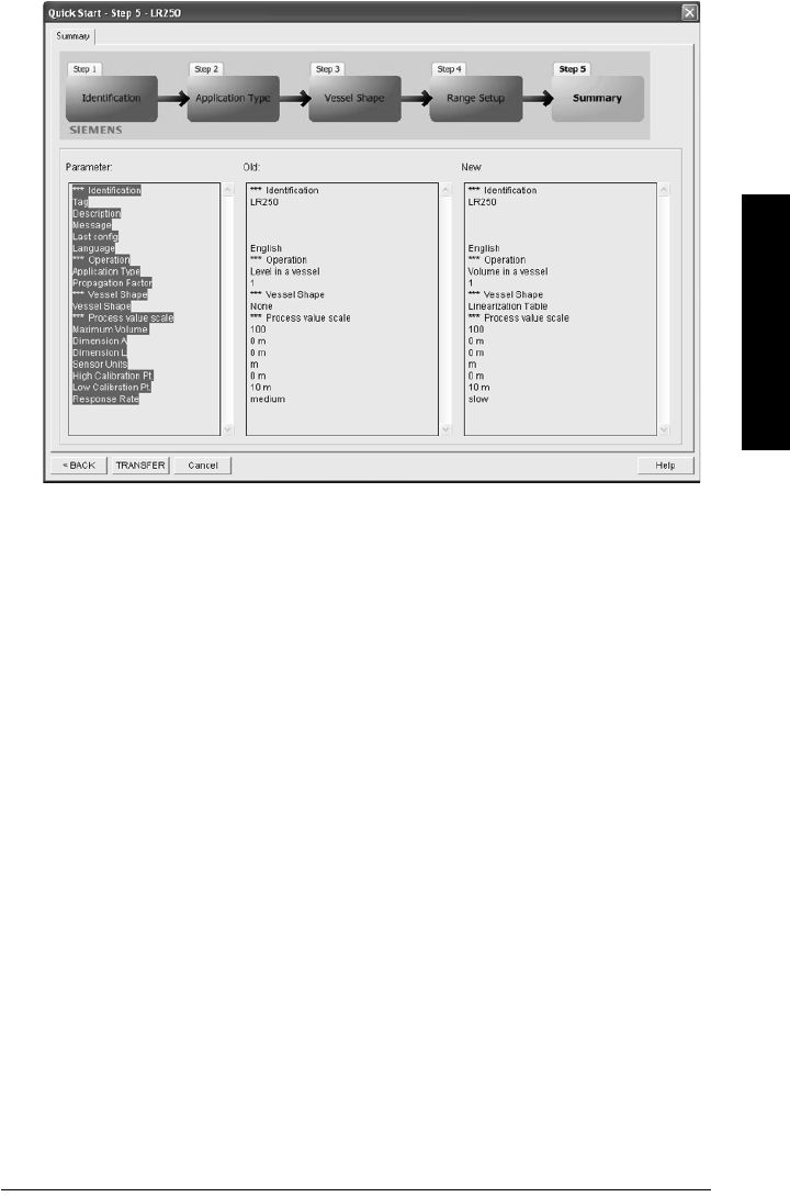
Step 5 – Summary
Check parameter settings, and click BACK to return and revise values, or FINISH to
transfer values to the device.
The message Quick Setup was successful will appear. Click OK.
Using Linearization via the Quick Start wizard
You can use the linearization feature to define a more complex vessel shape and enter up
to 32 level breakpoints where the corresponding volume is known. The values
corresponding to 100% and 0% levels must be entered. The breakpoints can be ordered
from top to bottom, or the reverse.
Ex ample:
Note: values are for example purposes only.
420
9
5
0
Breakpoint
number
3
2
1
Breakpoint
Number
Level value
(m)
Volume value
(l)
10 0
25500
393000
4208000
Level
value
7ML19985JE01 SITRANS LR250 (HART) – INSTRUCTION MANUAL Page 43
mmmmm
Quick Start
Open the menu Device – Quick Start:
1. In Step 1 – Identification, press Next, to accept default values.
2. In Step 2 – Application, select a volume application type, for example Volume in a
vessel, and press Next.
3. In Step 3 – Vessel Shape, choose the vessel shape option Linearization Table and
click Linearization.
a. In the Linearization window click on the appropriate Breakpoint tab to open the
dialog window.
linearization
Breakpoints 1 - 8
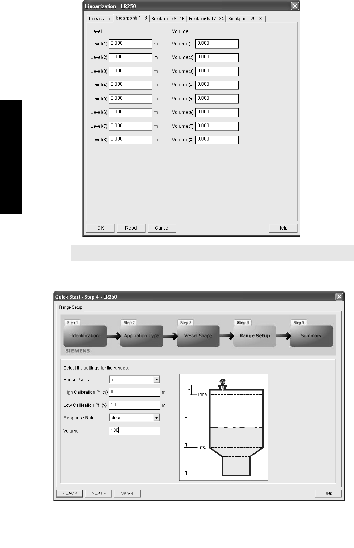
Page 44 SITRANS LR250 (HART) – INSTRUCTION MANUAL 7ML1998JE01
mmmmm
Quick Start
b. Enter the desired level and volume values, and press OK.
c. In the Step 3 window, click NEXT.
4. In Step 4 – Range Setup, enter parameter values, and click NEXT.
Note: Reset resets values to the values in the offline table.
7ML19985JE01 SITRANS LR250 (HART) – INSTRUCTION MANUAL Page 45
mmmmm
Quick Start
5. In Step 5 – Summary, check parameter values. Click BACK to return and revise
values, or FINISH to transfer values to the device.
The message Quick Setup was successful will appear. Click OK.
Page 46 SITRANS LR250 (HART) – INSTRUCTION MANUAL 7ML19985JE01
mmmmm
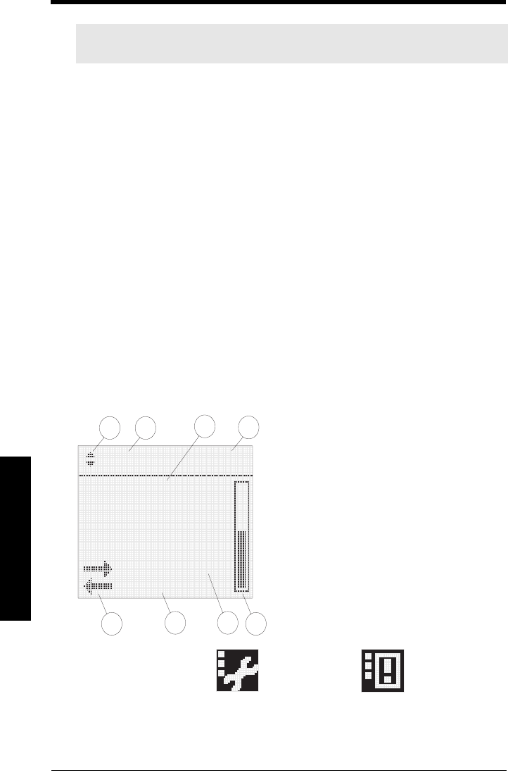
Local Interface
Local Operation Interface
• The handheld programmer allows you to change parameter values and set
operating conditions to suit your specific application.
• View settings on the LCD display, or request an echo profile, in PROGRAM mode.
• View the measured value and additional status information, on the LCD display in
Measurement mode (RUN mode).
Parameter access
Parameters are identified by name and organized into function groups, then arranged in a
hierarchical menu structure (see
LCD menu structure
on page 115). For example:
The LCD Display
Measurement mode (RUN mode)
Normal operation
If more than one fault is present, the status indicator and text for each fault alternate at
2 second intervals. See
General Fault Codes
on page 79 for a list.
Note: The complete range of parameters is only accessible via PDM. See
Parameter
Reference
on page 47 for a complete list with instructions.
2. SETUP
2.2. INPUT
2.2.1 SENSOR CALIB
2.2.1.13. RESPONSE RATE
LEVEL
[M]
21.40 °C
DATA EXCH.
18.91
134
2
65
7
8
1 – measured value (level, space or distance)
2 – toggle indicator for linear values or %
3 – level, distance, or space
4 – units
5 – bar graph indicates level
6 – secondary region indicates electronics
temperature, echo confidence, loop
current, or distance in response to a key
press. (See
Key functions in
Measurement mode
on page 47).
7 – text area displays status messages
8 – device status indicator
S: 0 LOE S: 53 CONFIG LO
Fault present
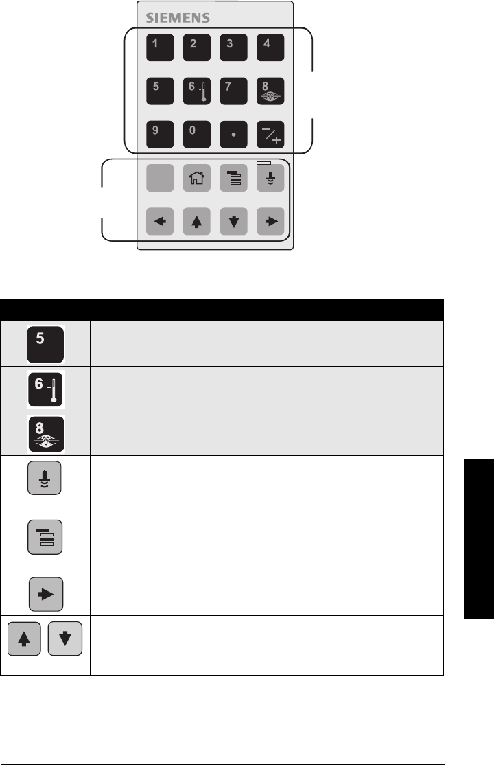
7ML19985JE01 SITRANS LR250 (HART) – INSTRUCTION MANUAL Page 47
mmmmm
Local Interface
Handheld Programmer (Part No. 7ML5830-2AJ)
Key functions in Measurement mode
Key Function Result
Updates the loop
current. New value is displayed in LCD secondary region.
Updates internal
enclosure temperature
reading.
New value is displayed in LCD secondary region.
Updates echo
confidence value. New value is displayed in LCD secondary region.
Updates distance
measurement. New value is displayed in LCD secondary region.
Mode opens
PROGRAM mode.
Opens the menu level last displayed in this power cycle,
unless power has been cycled since exiting PROGRAM
mode or more than 10 minutes have elapsed since
PROGRAM mode was used. Then top level menu will be
displayed.
Right ARROW
opens PROGRAM
mode.
Opens the top level menu.
Up or Down ARROW
toggles between
linear units and
percent.
LCD displays measured value in either linear units or
percent.
C
numeric keys
function keys
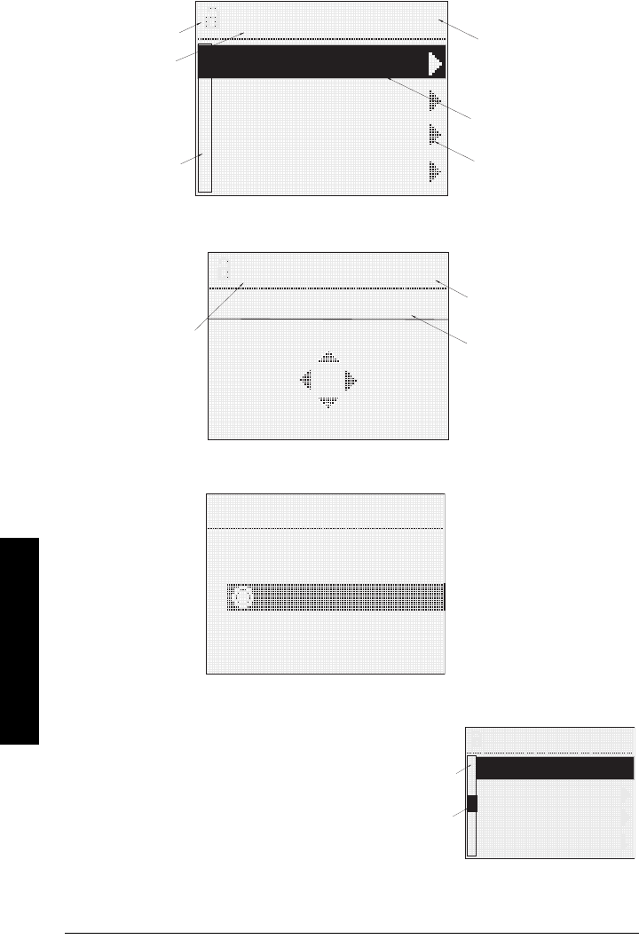
Page 48 SITRANS LR250 (HART) – INSTRUCTION MANUAL 7ML19985JE01
mmmmm
Local Interface
PROGRAM mode display
Navigation view
Parameter view
Edit view
Menu bar in navigation view
INPUT 2.2.1
SENSOR CALIB
VOL CONVERSION
VOLUME BREAKPT
ECHO PROC.
SENSOR CALIB
current item
number
lock/unlock
icon
pointer
current item
current
menu
menu bar
(see below
for details)
parameter
name
parameter
number
parameter
name
APPLICATIO..
2.2.1.2
LIQUID
PREVIOUS
NEXT
BACK EDIT
APPLICATIO..
2.2.1.2
SOLID
LIQUID LOW DK
LIQUID
• A visible menu bar indicates the menu list is
too long to display all items.
• The depth and relative position of the item
band on the menu bar indicates the length of
the menu list, and approximate position of the
current item in the list.
• A deeper band indicates fewer items.
• A band halfway down the menu bar indicates
the current item is halfway down the list.
SENSOR CAL
2.2.1.6
LOW CALIB. PT.
HIGH CALIB. PT.
NEAR RANGE
FAR RANGE
LOW CALIB. PT.
HIGH CALIB. PT.
menu
bar
item
band
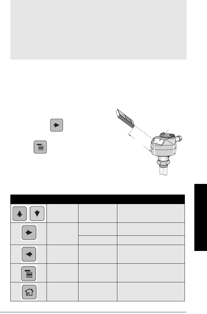
7ML19985JE01 SITRANS LR250 (HART) – INSTRUCTION MANUAL Page 49
mmmmm
Local Interface
Programming via the handheld programmer
The handheld programmer allows you to change parameter values and set operating
conditions to suit your specific application.
• For the complete list of parameters with instructions, see
Parameter Reference
on page 47.
•See
LCD menu structure
on page 115 for a chart.
1. Enter PROGRAM mode
• Point the programmer at the display (from a
maximum distance of 600 mm [2 ft.]).
•Right ARROW activates PROGRAM
mode and opens menu level 1.
•Mode opens the menu level last
displayed in PROGRAM mode within the
last 10 minutes, or menu level 1 if power
has been cycled since then.
2. Navigating: key functions in Navigation mode
Notes:
• Do not use the Quick Start settings if you want to modify an individual parameter.
• The Quick Start wizard groups the settings required for a simple application into one
package and the settings are inter-related.
• Because the settings are inter-related, the initial Quick Start parameter values are
not default values and do not necessarily reflect the current device configuration.
• SITRANS LR250 automatically returns to Measurement mode after a period of
inactivity in PROGRAM mode (between 25 seconds and 10 minutes, depending on
the menu level).
Key Name Menu level Function
Up or Down
ARROW menu or parameter Scroll to previous or next menu or
parameter.
Right ARROW menu Go to first parameter in the selected
menu, or open next menu.
parameter Open Edit mode.
Left ARROW menu or parameter Open parent menu.
Mode menu or parameter Change to MEASUREMENT mode.
Home menu or parameter Open top level menu at first item:
menu 1, item 1.
display
handheld programmer
(ordered separately)
Max. 600 mm (2 ft)
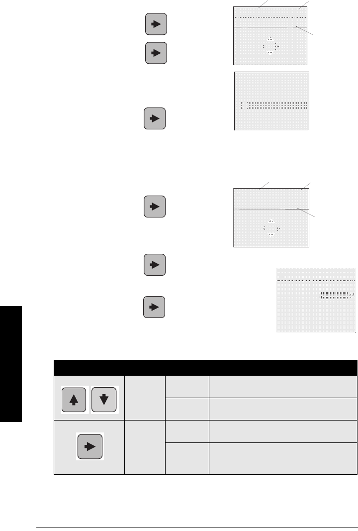
Page 50 SITRANS LR250 (HART) – INSTRUCTION MANUAL 7ML19985JE01
mmmmm
Local Interface
3. Editing in PROGRAM mode
Selecting a listed option
a. Navigate to the desired parameter.
b. Press Right ARROW to open
parameter view.
c. Press Right ARROW again to open
Edit mode. The current selection is
highlighted.
Scroll to a new selection.
d. Press Right ARROW to accept it
The LCD returns to parameter view and
displays the new selection.
Changing a numeric value
a. Navigate to the desired parameter.
b. Press Right ARROW to open
parameter view. The current value is
displayed.
c. Press Right ARROW again to open Edit mode.
The current value is highlighted.
d. Key in a new value.
e. Press Right ARROW to accept it. The LCD returns
to parameter view and displays the new selection.
Key functions in Edit mode
Key Name Function
Up or
Down
ARROW
Selecting
options Scrolls to item.
Numeric
editing
- Increments or decrements digits
- Toggles plus and minus sign
Right
ARROW
Selecting
options
- Accepts the data (writes the parameter)
- Changes from Edit to Navigation mode
Numeric
editing
- Moves cursor one space to the right
- or with cursor on Enter sign, accepts the data
and changes from Edit to Navigation mode
parameter
name
current
selection
parameter
number
APPLICATIO..
2.2.1.2
LIQUID
PREVIOUS
NEXT
BACK EDIT
APPLICATIO..
2.2.1.2
SOLID
LIQUID LOW DK
LIQUID
current
value
parameter
number
LOW CALIB..
2.2.1.6
20.000 M
PREVIOUS
NEXT
BACK EDIT
parameter
name
LOW CALIB..
2.2.1.6
20.000 M
+20.000
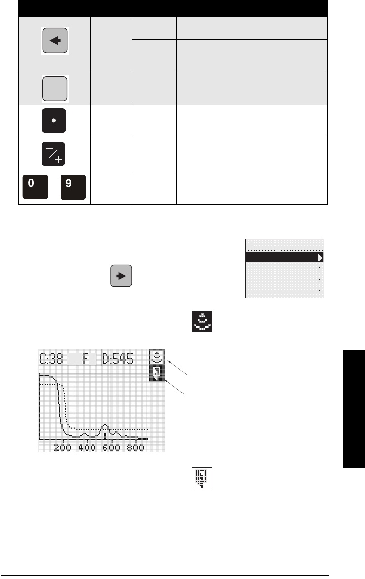
7ML19985JE01 SITRANS LR250 (HART) – INSTRUCTION MANUAL Page 51
mmmmm
Local Interface
Echo Profile Viewing
1. In PROGRAM mode, navigate to LEVEL METER >
DIAGNOSTICS > ECHO PROFILE
2. Press Right ARROW to request a profile.
3. In the Profile screen, press Up ARROW
to select the Transmit icon, and
Right ARROW to update the profile.
4. Press Down ARROW to select the Exit
icon, then Right ARROW to return to
previous menu.
Left
ARROW:
Selecting
options
Cancels Edit mode without changing the
parameter
Numeric
editing
- Moves cursor to plus/minus sign if this is the
first key pressed
- or moves cursor one space to the left.
Clear Numeric
editing Erases the display.
Decimal
point
Numeric
editing Enters a decimal point.
Plus or
minus sign
Numeric
editing Changes the sign of the entered value.
to
Numeral Numeric
editing Enters the corresponding character.
Key Name Function (Cont’d)
C
DIAGNOSTICS
3.1
ECHO PROFILE
MEAS. VALUES
REMAIN. DEV. LIFE
REMAIN. SENS.LIFE
ECHO PROFILE
MEAS. VALUES
REMAIN. DEV. LIFE
REMAIN. SENS.LIFE
transmit icon, selected
transmit icon, unselected
exit icon, selected
exit icon, unselected

Page 52 SITRANS LR250 (HART) – INSTRUCTION MANUAL 7ML19985JE01
mmmmm
SIMATIC PDM
Operating SITRANS LR250 via
SIMATIC PDM
SIMATIC PDM is a software package used to commission and maintain SITRANS LR250 and
other process devices. Please consult the operating instructions or online help for details on
using SIMATIC PDM. (You can find more information at www.fielddevices.com: go to Products
and Solutions > Products and Systems > Process Device Manager.)
Functions in SIMATIC PDM
SIMATIC PDM monitors the process values, alarms and status signals of the device. It allows
you to display, compare, adjust, verify, and simulate process device data.
For information on adjusting parameter values and viewing the results, see
Alternatively, enter
values for Point and Offset directly into the dialog boxes.
on page 56 and
Accessing Functions
on page 57.
SIMATIC PDM Rev. 6.0, SP2 Features
The graphical interface facilitates the following tasks:
• Configuring LR250 for a simple application: see
Quick Start Wizard via SIMATIC
PDM
on page 38.
• Volume measurement in an irregular vessel: see
Using Linearization via the Quick
Start wizard
on page 42.
• Level monitoring: see
Online Display
on page 53
• Echo monitoring: see
Echo profile saving
on page 56
• Level trend monitoring: see
Alternatively, enter values for Point and Offset directly
into the dialog boxes.
on page 56
• False Echo Suppression: see
Auto False Echo Suppression Setup
on page 55 and
Manual TVT Shaper
on page 56.
Accessing Functions
You have access to a number of functions via pull-down menus from the menu bar View
menus include: Display (real-time), Echo Profile, and Trend (level over time) diagram, among
others.
Note: For a complete list of parameters with instructions, see Parameter Reference
starting on page 61.
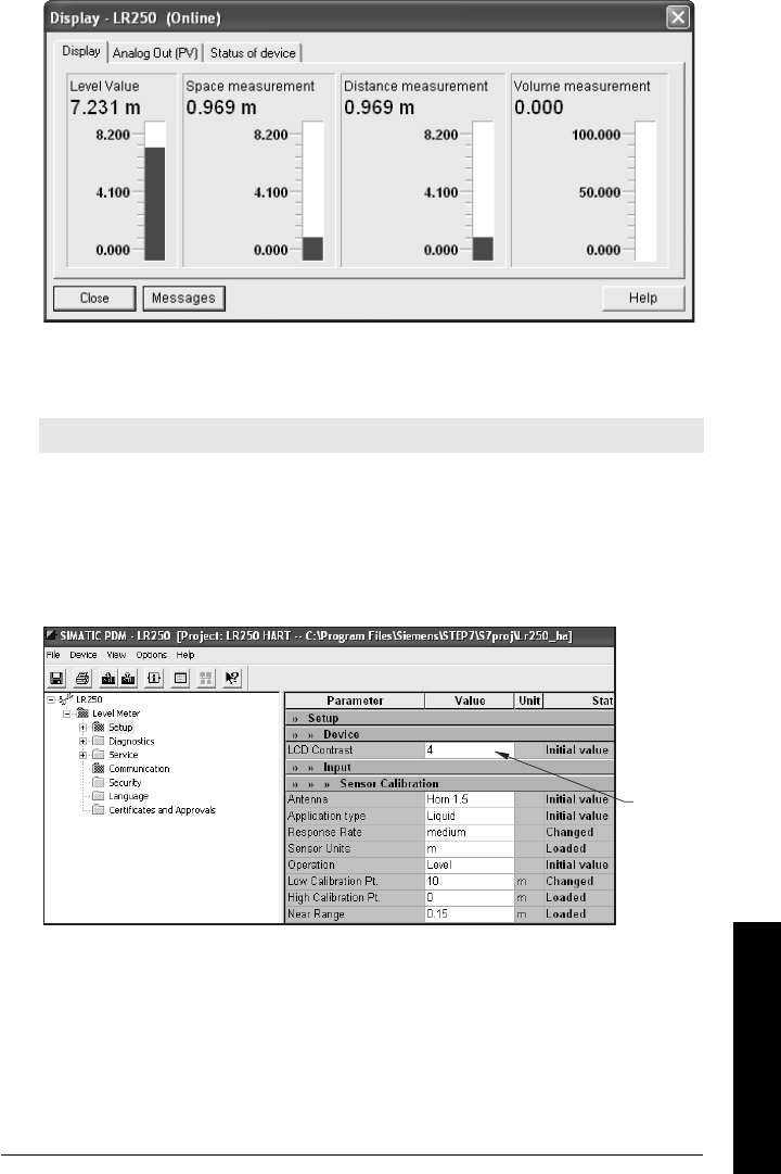
7ML19985JE01 SITRANS LR250 (HART) – INSTRUCTION MANUAL Page 53
mmmmm
SIMATIC PDM
Online Display
The online display allows you to compare outputs in real time. Open the menu View – Display.
Changing parameter settings using SIMATIC PDM
1. Launch SIMATIC PDM, connect to SITRANS LR250, and upload data from the
device.
2. Adjust parameter values in the parameter value field then press Enter. The status
fields read Changed..
3. Open the Device menu, click on Download to device, then use File – Save, to save
parameter settings. The status fields are cleared.
Parameters accessed via pull-down menus
See
Pull-down menus via SIMATIC PDM
on page 43 for a complete list of parameters that can
be accessed only via pull-down menus in SIMATIC PDM.
Note: For a complete list of parameters, see
Parameter Reference
on page 61.
value
fields

Page 54 SITRANS LR250 (HART) – INSTRUCTION MANUAL 7ML19985JE01
mmmmm
SIMATIC PDM
Configuring a new device
Device Description (DD)
You will need the DD for SIMATIC PDM version 6.0 with SP2. You can locate the DD in
Device Catalog, under Sensors/Level/Echo/Siemens Milltronics/SITRANS LR 460. If you do
not see SITRANS LR 460 under Siemens Milltronics, you can download the DD from the
product page of our website at: https://pia.khe.siemens.com/index.asp?Nr=14655, under
Downloads.
Save the files to your computer, and extract the zipped file to an easily accessed location.
Launch SIMATIC PDM – Manager Device Catalog, browse to the unzipped DD file and
select it.
1. Set Address (default for PROFIBUS PA is 126; for HART is 0).
• Point the handheld programmer at the display then press Mode to activate
PROGRAM mode, menu item 1.0.
• Press Down ARROW , Right ARROW , Right ARROW to navigate to
Address (menu item 2.1.2).
• Press Right ARROW to open Edit mode: the PROGRAM icon will flash.
• If required, key in a new value and press Right ARROW to accept it. The LCD
displays the new value and the PROGRAM icon disappears.
2. You will need the most up-to-date Device Description (DD) for your instrument.
Launch SIMATIC PDM – Manager Device Catalog, browse to the unzipped DD file
and select it.
3. Launch SIMATIC Manager and create a new project for LR 460. Application Guides
for setting up HART and PROFIBUS PA devices with SIMATIC PDM.can be
downloaded from the product page of our website at:
https://pia.khe.siemens.com/index.asp?Nr=14655
4. Open the Menu Device – Reset and click on Factory Reset.
5. Upload parameters to the PC/PG.
6. Calibrate the device.
Calibrating LR 460 via PDM
•See
Quick Start Wizard via SIMATIC PDM
on page 30 and follow 4 steps to setup
for a simple application.
• Open the menu Device – Sensor Calibration to set parameters individually.
• For a complete list of parameters see
Parameter Reference
on page 43.

7ML19985JE01 SITRANS LR250 (HART) – INSTRUCTION MANUAL Page 55
mmmmm
SIMATIC PDM
Reset
Device Reset
This has the same effect as cycling power. It does not reset any parameters.
Factory Reset
Use Factory Reset to reset all parameters excluding device addresses to the default
settings.
1. Open the menu Device – Reset and click on Factory Reset.
2. After the reset is complete upload parameters to the PC/PG.
Configuration Flag Reset (HART only)
To reset the configuration flag to zero, open the menu Device – Configuration Flag Reset
and execute a reset.
Auto False Echo Suppression
Use this parameter to learn a new TVT curve, to avoid false echoes caused by
obstructions. See
Auto False-Echo Suppression
on page 71 for a more detailed
explanation, and
Auto False Echo Suppression
on page 74 for instructions
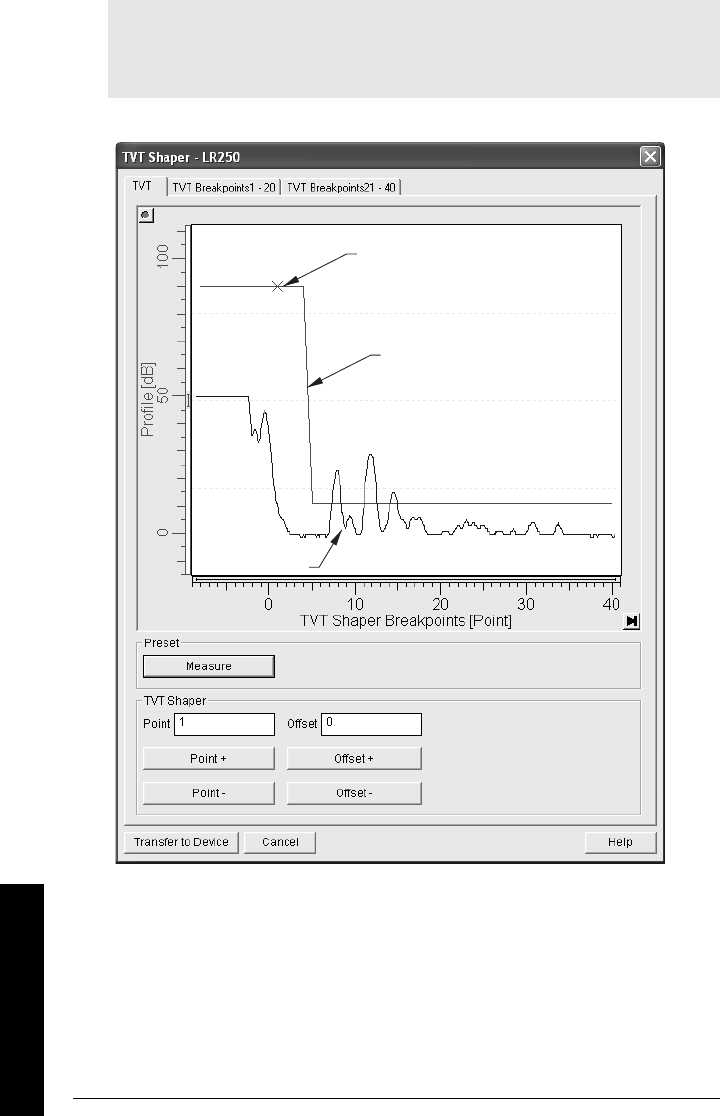
Page 56 SITRANS LR250 (HART) – INSTRUCTION MANUAL 7ML19985JE01
mmmmm
SIMATIC PDM
Manual TVT Shaper
Open the menu Device – TVT Shaper
• Change the position of the X cursor on the TVT curve using the Point+ and Point–
buttons: raise and lower the curve using Offset+ and Offset–.
• Alternatively, enter values for Point and Offset directly into the dialog boxes.
Notes:
• For more details, see
Auto False-Echo Suppression
on page 75.
• Double click each axis and record the Xscale and Data Scale values, so that you can
restore the default view by resetting to these values.
TVT curve
X cursor
echo profile
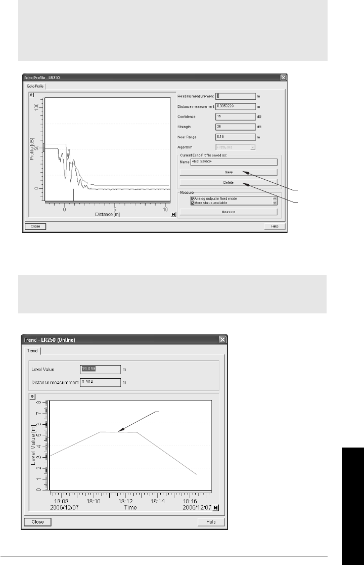
7ML19985JE01 SITRANS LR250 (HART) – INSTRUCTION MANUAL Page 57
mmmmm
SIMATIC PDM
Echo profile saving
Trend Diagram (Level Trend over Time)
Open the menu View – Trend
Notes:
• Double click each axis and record the Xscale and Data Scale values, so that you can
restore the default view by resetting to these values.
• You can save a profile or delete a saved profile.
• After saving a profile open menu View – Show echo profile.
Notes:
• Double click each axis and record the Xscale and Data Scale values, so that you can
restore the default view by resetting to these values.
delete
save
trend line
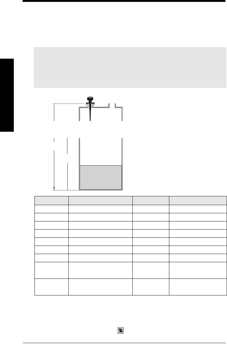
Page 58 SITRANS LR250 (HART) – INSTRUCTION MANUAL 7ML19985JE01
mmmmm
Applications
Application Examples
You can use these examples as setup references. Enter the values in the parameter
tables to select the corresponding functions.
Example 1: Liquid resin in storage vessel, level
measurement
Return to Measurement: press Mode to start normal operation.
Notes:
• The minimum distance from the flange face to the target is limited by near range
2.2.1.11.
• Only set 2.2.5.6 (Auto False Echo Suppression) if the product is at least 2 m (78”)
away from the flange face. If it is closer, leave 2.2.5.6 at 1 until the level drops
and the distance increases beyond 2 m (78”).
Parameter Description Value Function
2.2.1.5 operation Level Level
2.2.7.1 measurement response Med 1 m/minute
2.2.1.4 units Mmeters
2.2.1.6 low calibration point 55 m
2.2.1.7 high calibration point 4.5 4.5 m
2.4.1 Failsafe timer 22 minutes
2.4.2 Failsafe Material Level HI Hi
2.2.5.7 Auto False-Echo
Suppression Distance
[Distance1
minus 0.42 m]
1. Distance to product from reference point.
Sets length of learned
TVT curve2 to use
2. For more details see
Range (Auto Suppression Range)
on page 75 and
Auto
False Echo Suppression
on page 74.
2.2.5.6 Auto False-Echo
Suppression
2 then
1
Enables the use of
learned TVT curve2.
The application is to obtain a level
measurement and corresponding 4 to 20 mA
output proportional to resin levels in a
storage vessel.
Low Calibration Point is the bottom of the
tank, which is 5 m from the antenna flange
face. High Calibration Point is 4.5 m from the
vessel bottom. The maximum rate of filling or
emptying is about 0.2 m/min.
In the event of a loss of echo, SITRANS LR250
is to go into Failsafe Hi after 2 minutes.
4.5 m
Low Cal
Point
5 m 100% Level
0% Level
High
Cal
Point
Sensor
reference
point
GRAPHIC TO BE UPDATE
D
7ML19985JE01 SITRANS LR250 (HART) – INSTRUCTION MANUAL Page 59
mmmmm
Applications
Example 2: Horizontal vessel with volume measurement
The application is to obtain a level measurement and corresponding 4 to 20 mA output
proportional to vessel volume in a chemical vessel.
Low Calibration Point is the bottom of the tank, which is 3.5 m from the antenna flange
face. High Calibration Point is 3.0 m from the vessel bottom. The maximum rate of filling or
emptying is about 0.2 m/min. Selecting tank shape i at 2.2.2.1 (Vessel Shape), and entering
values for A and L, will give a volume reading instead of level.
In the event of a loss of echo, SITRANS LR250 is to go into Failsafe Hi after 2 minutes.
Notes:
• The minimum distance from the flange face to the target is limited by near range
2.2.1.11.
• Only set 2.2.5.6 Auto False Echo Suppression if the product is at least 2 m (78”)
away from the flange face. If it is closer, leave 2.2.5.6 at 1 until the level drops
and the distance increases beyond 2 m (78”).
Volume
reading
3.0 m
3.5 m
A
2.2.3.2
A
2.2.3.2
L
2.2.3.3
Hi Cal
Point
Low
Cal
Point
100% = 8000 liters
Sensor
reference
point
GRAPHIC TO BE UPDATE
D
Page 60 SITRANS LR250 (HART) – INSTRUCTION MANUAL 7ML19985JE01
mmmmm
Applications
Return to Measurement: press Mode to start normal operation.
Parameter Description Values Function
2.2.1.5 operation Level Volume replaces Level when
a tank shape is selected at
2.2.2.1
2.2.7.1 measurement
response
Med 1 m/minute
2.2.1.4 units Mmeters
2.2.1.6 low calibration point 3.5 3.5 m
2.2.1.7 high calibration point 33 m
2.2.2.1 vessel shape iparabolic ends
2.2.3.1 maximum volume 8000 8000 liters
2.2.3.2 vessel dimension A .8 0.8 meters
2.2.3.3 vessel dimension L 66 meters
2.4.1 Failsafe timer 22 minutes
2.4.2 Failsafe HI Hi
2.2.5.7
Auto False-Echo
Suppression Range
[Distance1
minus 0.42 m]
1. Distance to product from reference point.
Sets length of learned TVT
curve2 to use
2. For more details see
Range (Auto Suppression Range)
on page 75 and
Auto
False Echo Suppression
on page 74. For an explanation, see
Auto False-Echo
Suppression
on page 108.
2.2.5.6 Auto False-Echo
Suppression
2 then
1
Enables the use of learned
TVT curve2.

7ML19985JE01 SITRANS LR250 (HART) – INSTRUCTION MANUAL Page 61
mmmmm
Parameters
Parameter Reference
Parameters are identified by name and organized into function groups. Menus arranged
on up to five levels give access to associated features and options.
Parameters accessible via the handheld programmer are preceded by a number. (See
LCD menu structure
on page 115 for a chart.) Parameters not preceded by a number are
accessible only via SIMATIC PDM.
Some parameters are accessible in SIMATIC PDM via pull-down menus. Where those
parameters can also be accessed via the handheld programmer, they are found in the
numbered list, and directions for SIMATIC PDM are given beside the individual
parameter. Page references for further information can be found under
Pull-down menus
via SIMATIC PDM
below.
Pull-down menus via SIMATIC PDM
Quick Start Wizard
The Quick Start wizard groups together all the settings you need to configure for a simple
application.
• The wizard is a complete package and settings are inter-related.
• Because the settings are inter-related, the initial Quick Start parameter values are
not default values and do not necessarily reflect the current device configuration.
• Do not use the wizard to modify individual parameters.
• You can access the Quick Start wizard either via SIMATIC PDM, or via the handheld
programmer.
Device menus page View menus page
Communication path - Display -
Download to device
Upload to PC/PG
Update diagnostic status
-
-
-
Trend
Echo Profile
Show Echo Profile
Status
Read Analog Value
Clear Faults
Peak Values
Wear
37
37
37
-
-
-
52
48
Quick Start
Auto False Echo Suppression
TVT shaper
62
74
76
Maintenance
Selftest
Reset
Configuration Flag Reset
87
-
87
-
D/A Trim
Write Locking
42
48
Simulate AO 42
HART Communication
Simulation
87
42
Sensor Calibration 50
Page 62 SITRANS LR250 (HART) – INSTRUCTION MANUAL 7ML19985JE01
mmmmm
Parameters
1. Quick Start
1.1. Application Type
1.2. Response Rate
Sets the reaction speed of the device to measurement changes in the target range.
Use a setting just faster than the maximum filling or emptying rate (whichever is
greater). Slower settings provide higher accuracy: faster settings allow for more level
fluctuation
1.3. Sensor Units
Select the units for the Quick Start variables (high and low calibration point, and level,
distance, or space).
1.4. Operation
Operation types1
Options
LIQUID
SOLID
LIQUID LOW DK (low dielectric liquid)
Options
SLOW 0.1 m/minute
MED 1.0 m/minute
FAST 10.0m/minute
Options M, CM, MM, FT, IN
Options
NO SERVICE
LEVEL Distance to material surface referenced from Low Calibration
Point (process empty level).
SPACE Distance to material surface referenced from High Calibration
Point (process full level).
DISTANCE Distance to material surface referenced from Sensor
Reference Point.
1. The point from which level measurement is referenced. See
SITRANS LR 200 Dimen-
sions
on page 14 for the standard rod antenna. See
Appendix D: Flange Adapter Ver-
sions
on page 83 for other configurations.
high
calibration
point
low calibration point
level
space
distance
sensor reference point1

7ML19985JE01 SITRANS LR250 (HART) – INSTRUCTION MANUAL Page 63
mmmmm
Parameters
1.5. Low Calibration Point
Distance from Sensor Reference to Low Calibration Point: usually process empty
level. (See Operation types for an illustration.)
1.6. High Calibration Point
Distance from Sensor Reference to High Calibration Point: usually process full level.
(See Operation types for an illustration.)
1.7. Apply? (Apply changes)
In order to save the Quick Start settings it is necessary to select Yes and apply
changes.
2. Setup
2.1. Device
2.1.1. LCD Contrast
Allows you to adjust the LCD contrast. to improve readability.
2.2. Input
2.2.1. Sensor Calibration
2.2.1.1. Antenna
Identifies horn configuration and automatically adjusts the Near Range
(blanking) distance to suit.
Use this parameter to reset the Near Range (blanking) distance, if your horn
has to be replaced by one of a different type.
Values Range: 0.0000 to 20.000 m
Values Range 0.0000 to 20.000 m
Options YES, NO
Notes:
• See
Programming via the handheld programmer
on page 32 or
Appendix M:
Operating SITRANS LR 200 (PROFIBUS PA) via SIMATIC PDM
on page 118 for
instructions.
• Default settings in the parameter tables are indicated with an asterisk (*) unless
explicitly stated.
• Values shown in the following tables can be entered via the handheld programmer.
Values Range: 0 (High contrast) to 20 (Low contrast). Default: 8
Options 1.5" horn
2" horn
3" horn
4" horn
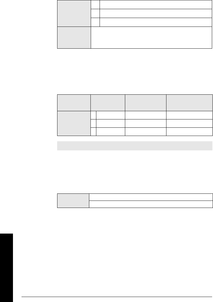
Page 64 SITRANS LR250 (HART) – INSTRUCTION MANUAL 7ML19985JE01
mmmmm
Parameters
2.2.1.2. Application
Automatically configures the device to operate in the chosen application
type, by changing one or more of the following parameters: 2.2.1.14.
Propagation Factor , 2.2.4.1.2. Position , and/or 2.2.4.4.3. Low dK Material
Tracking .
You can configure each of the related parameters, to suit your particular
application.
2.2.1.3. Response Rate
Sets the reaction speed of the device to measurement changes in the target
range.
Use a setting just faster than the maximum filling or emptying rate
(whichever is greater). Slower settings provide higher accuracy: faster
settings allow for more level fluctuation.
2.2.1.4. Sensor Units
Units the sensor is measuring in.
Options
SOLID
*LIQUID
LIQUID LOW DK (low dielectric liquid)
Related
parameters
2.2.1.14. Propagation Factor
2.2.4.1.2. Position
2.2.4.4.3. Low dK Material Tracking
Related
parameters
Response
Rate Fill Rate Empty Rate
*slow 0.1 m/minute 0.1 m/minute
medium 1 m/minute 1 m/minute
fast 10 m/minute 10 m/minute
Note: Changing Response Rate resets Fill Rate and Empty Rate.
Values m, cm, mm, ft, in
Default: m
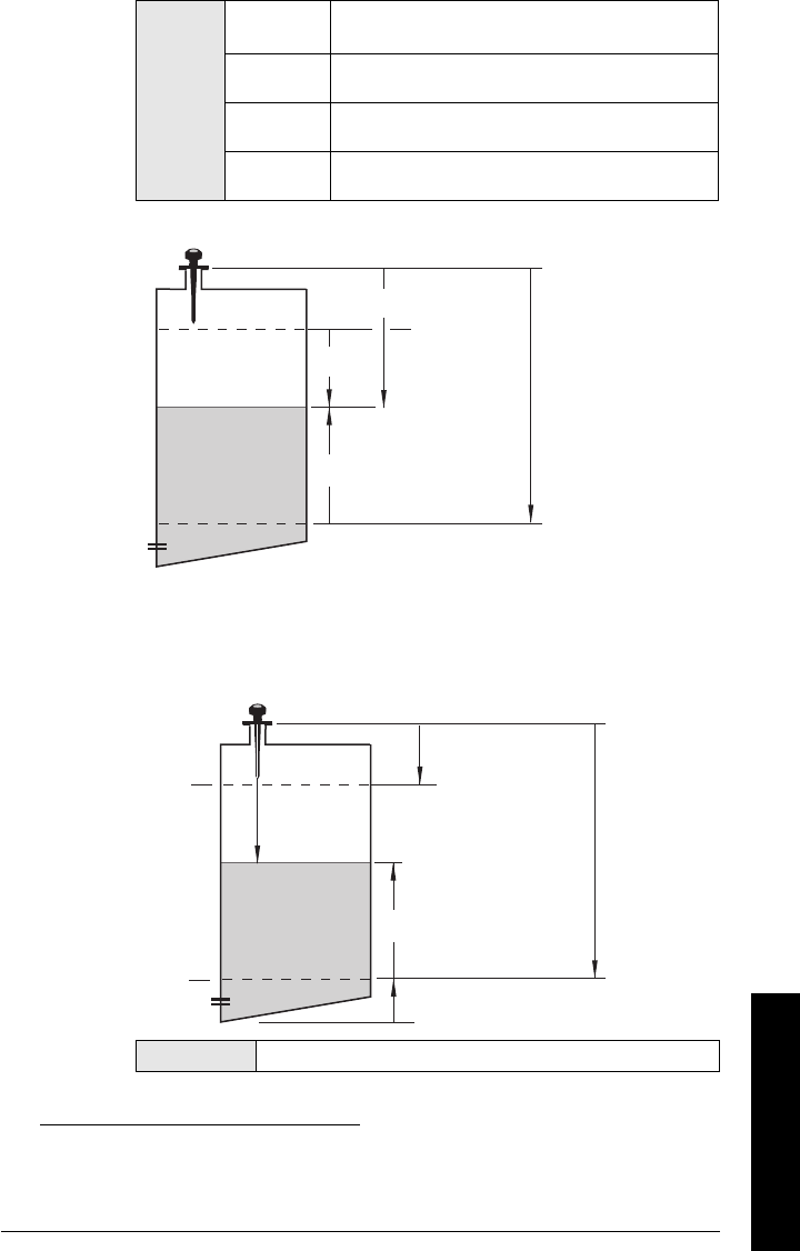
7ML19985JE01 SITRANS LR250 (HART) – INSTRUCTION MANUAL Page 65
mmmmm
Parameters
2.2.1.5. Operation
Operation types1
2.2.1.6. Low Calibration Pt.
Distance from Sensor Reference to Low Calibration Point (corresponding to
Low Level Point). Unit is defined in Sensor units. (In SIMATIC PDM, go to
Device menu > Sensor Calibration, then click on Additional Information, to
see an illustration.)
2
Options
NO SER-
VICE
LEVEL Distance to material surface referenced from Low
Calibration Point (process empty level).
SPACE Distance to material surface referenced from High
Calibration Point (process full level).
DISTANCE Distance to material surface referenced from Sensor
Reference Point.
1. The point from which level measurement is referenced. See
SITRANS LR 200 Dimen-
sions
on page 14 for the standard rod antenna. See
Appendix D: Flange Adapter Ver-
sions
on page 83 for other configurations.
Values Range: 0 to 20 m. Default 20.000 m
high
calibration
point
low
calibration
point
level
space
distance
sensor
reference point1
High Level Point
(default: 100%)
sensor
reference
point2
Low Level Point
(default: 0%)
Level
Low
Calibration
Point
High
Calibration
Point
Level Offset
Sensor
value1
Page 66 SITRANS LR250 (HART) – INSTRUCTION MANUAL 7ML19985JE01
mmmmm
Parameters
2.2.1.7. High Calibration Pt.
Distance from Sensor Reference to High Calibration Point (corresponding to
High Level Point). Unit is defined in Sensor units. (In SIMATIC PDM, go to
Device menu > Sensor Calibration, then click on Additional Information, to
see an illustration.)
2.2.1.12. Near Range
The range in front of the device (measured from the sensor reference point)
within which any echoes will be ignored, defined in sensor units. This is
sometimes referred to as blanking or a dead zone. The factory set range is
dependent on the horn type.
Compensates, for example if the sensor head is changed.
2.2.1.13. Far Range
Allows the material level to drop below Low Calibration Point without
generating a Loss of Echo (LOE) state, defined in %. This is sometimes
referred to as Range Extension.
Use this feature if the measured surface can drop below the Low Cal. Point
in normal operation. Enter value as a percentage of Low Calibration Point.
2.2.1.14. Propagation Factor
Compensates for the change in microwave velocity from propagation in free
space.The value is used to compensate for changes in microwave velocity
due to propagation within a metal stillpipe, instead of in free space.
2. The value produced by the echo processing which represents the distance from sen-
sor reference point to the target.
Values Range: 0 to 20 m. Default 0.000 m
Options
Range: 0 to 20 m
Antenna Type Near Range Default Setting
1.5" horn 0.185 m (7.28")
2" horn 0.217 m (8.54")
3" horn 0.250 m (9.84")
4" horn 0.305 m (12.01")
Options Range: 0 to >1300 (max. value depends on Low Cal-
ibration Point settin). Default 5.000%
Values Range: 0.3000 to 1.5000
Default: 1.0 0 0
Pipe Size (I.D.)a
a. Since pipe dimensions may vary slightly, the propagation factor
may also vary.
Propagation Factor
50 mm (2”) 0.990
80 mm (3”) 0.996
100 mm (4”) 0.998
150 mm (6”) 0.999
200 mm (8”) 1.000
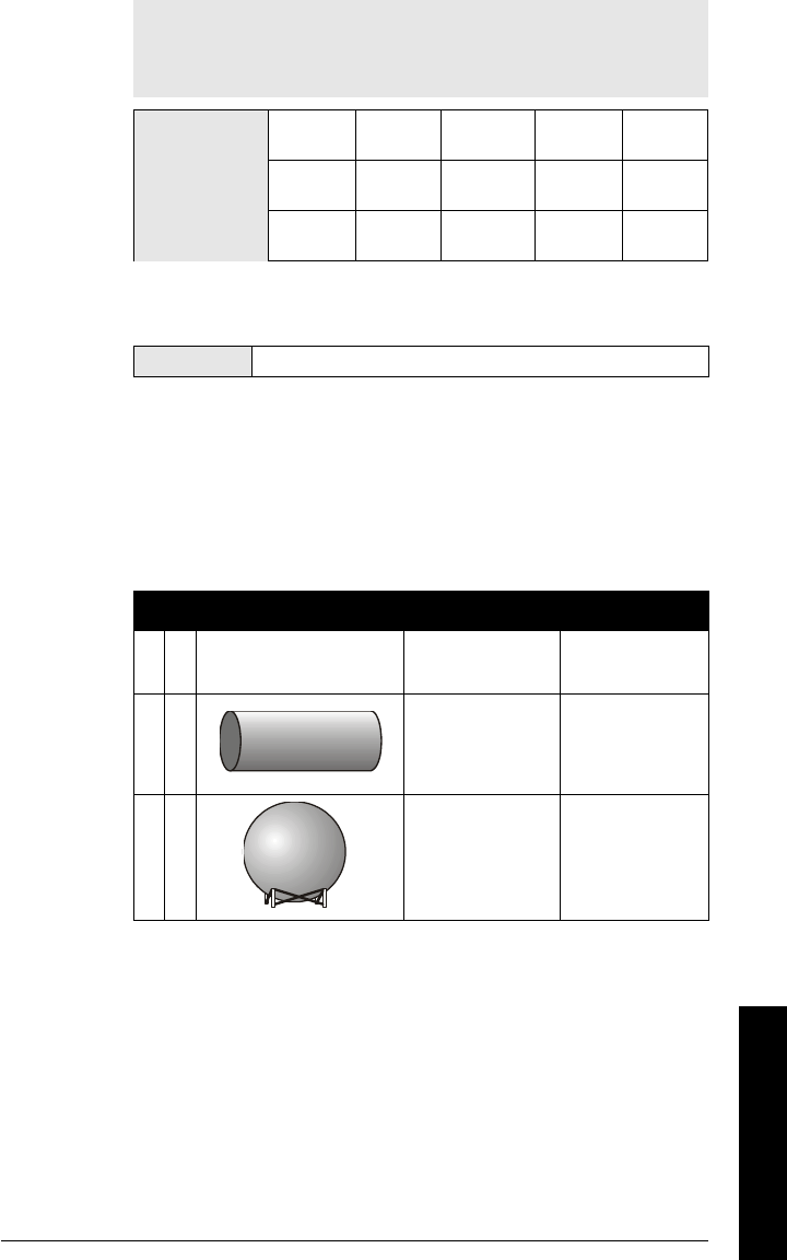
7ML19985JE01 SITRANS LR250 (HART) – INSTRUCTION MANUAL Page 67
mmmmm
Parameters
2.2.1.15. Level Offset
A constant offset that can be added to Level to form Level output. The unit is
defined in Sensor Units.
2.2.2. Volume conversion
Carries out a volume conversion from a level value.
2.2.2.1. Vessel Shape
Defines the vessel shape and allows the LR250 to calculate volume instead of
level. If "none" is selected, no volume conversion is performed. Select the
vessel shape matching the monitored vessel or reservoir.
Note: When operating with a waveguide antenna or stillpipe, values for
the parameter
2.2.4.4.3. Low dK Material Tracking
and for the propagation
factor should be set according to the antenna/pipe size: see the table
below..
Antenna/Pipe
Size (I.D.) 50 mm (2”) 80 mm (3”) 100 mm (4”) 150 mm
(6”)
200 mm
(8”)
Propagation
Factor 0.990 0.9957 0.9965 0.999 0.9994
Low dK material
tracking value
Cal Lo –
700 mm
Cal Lo –
1000 mm
Cal Lo –
1000 mm
Cal Lo –
1000 mm
Cal Lo –
1000 mm
Values Default: 0 m
Vessel Shape Description Also required
a* None no volume calculation
required N/A
bflat end horizontal
cylinder maximum volume
c sphere maximum volume
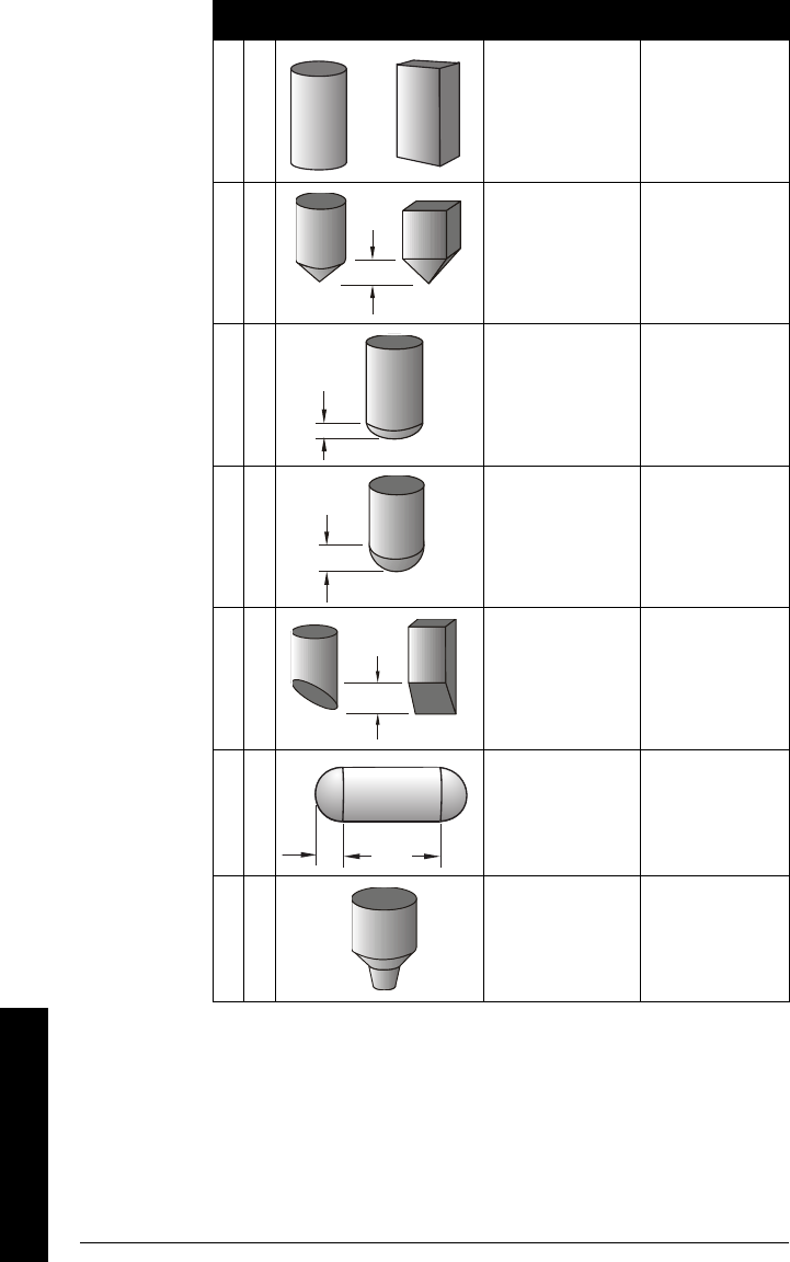
Page 68 SITRANS LR250 (HART) – INSTRUCTION MANUAL 7ML19985JE01
mmmmm
Parameters
dupright, linear (flat
bottom) maximum volume
e
conical or pyramidal
bottom maximum volume,
dimension A
f parabolic bottom maximum volume,
dimension A
g half-sphere bottom
maximum volume,
dimension A
h flat sloped bottom maximum volume,
dimension A
iparabolic end
horizontal cylinder
maximum volume,
dimension A,
dimension L
j
linearization table
(level/volume
breakpoints)
maximum volume,
level breakpoints,
volume breakpoints
Vessel Shape Description Also required
A
A
A
A
AL
7ML19985JE01 SITRANS LR250 (HART) – INSTRUCTION MANUAL Page 69
mmmmm
Parameters
2.2.3. Volume Breakpoints
2.2.3.1. Maximum Volume
The maximum volume of the tank. Enter the vessel volume corresponding to
High Calibration Point. For example, if your maximum vessel volume is 8000 L,
enter a value of 8000. The units of volume are not entered, but are implied.
2.2.3.2. Dimension A
The height of the vessel bottom in sensor units when the bottom is conical,
pyramidal, parabolic, spherical, or flat -sloped. If the vessel is horizontal with
parabolic ends, the depth of the end. See 2.2.2.1. Vessel Shape for an
illustration.
2.2.3.3. Dimension L
Length of the cylindrical section of a horizontal parabolic end vessel, in
sensor units. See 2.2.2.1. Vessel Shape for an illustration.
2.2.3.4. Table 1-8
If your vessel shape is more complex than any of the preconfigured shapes,
you can define the shape as a series of segments. A value is assigned to each
level breakpoint and a corresponding value is assigned to each volume
breakpoint. Level values are defined in sensor units. Volume units are defined
by the user but are not explicitly stated in the SITRANS LR250.
Enter up to 32 level breakpoints, where the corresponding volume is known.
The values corresponding to 100% and 0% levels must be entered. The
breakpoints can be ordered from top to bottom, or the reverse.
Breakpoints are grouped into four tables: Table 1-8, Table 9-16, Table 17-24,
and Table 25-32.
Entering breakpoints via the hand-held programmer:
a. Go to the appropriate table for the particular breakpoint you wish to
adjust: for example, go to Table 1-8 for breakpoint 1.
Values Range: 0.0000 to 99999
Default: 100.0
Related Parameters
Low Calibration Point
High Calibration Point
Vessel Shape
Values Range: 0.0000 to 99999 in units
Default: 0.0
Related Parameters Vessel Shape
Values Range: 0.0000 to 99999 in units
Default: 0.0
Related Parameters Vessel Shape
Level Values Range: 0.0000 to 99999 (m, cm, mm, ft, in)
Default: 0.0
Volume Values Range: 0.0000 to 99999
Default: 0.0
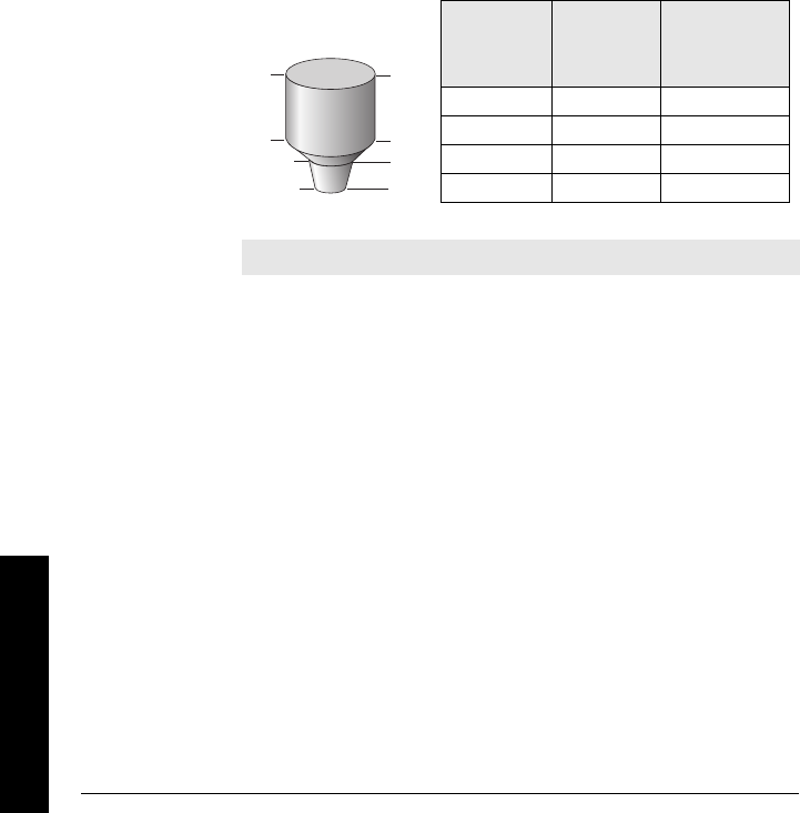
Page 70 SITRANS LR250 (HART) – INSTRUCTION MANUAL 7ML19985JE01
mmmmm
Parameters
a. Under Table 1-8, go to
2.2.3.4.1. Level 1
to enter the level value for the
breakpoint 1.
a. Under Table 1-8, go to
2.2.3.4.2. Vol 1
to enter the volume value for
the breakpoint 1
a. Repeat steps a to c, till values have been entered for all required
breakpoints.
2.2.3.4.1. Level 1
a. Press Right ARROW to open Edit mode.
b. Enter level value and press Right ARROW to accept it.
c. Press Down ARROW to move to corresponding volume
breakpoint.
2.2.3.4.2. Vol 1
a. Press Right ARROW to open Edit mode.
b. Enter volume value and press Right ARROW to accept it.
c. Press Down ARROW to move to next level breakpoint.
See example below for illustration.
Example:
Entering breakpoints via PDM:
a. Level values are defined in Sensor Units. If you want to change the
unit, go to Input > Sensor Calibration > Sensor Units and make a
new selection.
a. Go to > Volume conversion and select Linearization Table option.
a. Go to > Volume breakpoints > Table 1-8 and enter values for level
and volume breakpoints in table.
a. Repeat step c till values have been entered for all required
breakpoints using other tables as required.
Note: values are for example purposes only.
420
9
5
0
Breakpoint
number
3
2
1
Breakpoint
Number
Level
value
(m)
Volume
value
(l)
10 0
25500
3 9 3000
4 20 8000
Level
value
7ML19985JE01 SITRANS LR250 (HART) – INSTRUCTION MANUAL Page 71
mmmmm
Parameters
2.2.4. Echo Processing
2.2.4.1. Echo select
2.2.4.1.1. Algorithm
Selects the algorithm to be applied to the echo profile to extract the true
echo.
2.2.4.1.2. Position
Defines where on the echo the distance measurement is determined.
2.2.4.1.3. Echo Threshold
Sets the minimum echo confidence that the echo must meet in order to
prevent a Loss of Echo condition and the expiration of the LOE timer.
When Echo Confidence exceeds the Confidence Threshold, the echo is
evaluated.
Use this feature when an incorrect material level is reported.
Options
*FFirst echo
LLargest echo (reserved for SMPI service
personnel)
BLF Best of Largest or First echo (reserved for
SMPI service personnel)
Note: If dielectric of fluid to be monitored is less than 3, we recommend
setting Position to 4 (Hybrid) and
2.2.4.4.3. Low dK Material Tracking
to
0.5 m (1.64 ft).
Options
Center
*Hybrid (Center and CLEF)
CLEF (Constrained Leading Edge Fit)
Related
parameters
2.2.4.4.Tank Bottom Algorithm
(see below)
Values Range: 0 to 99
Default: 10
Related
Parameters LOE Timer

Page 72 SITRANS LR250 (HART) – INSTRUCTION MANUAL 7ML19985JE01
mmmmm
Parameters
2.2.4.2. Sampling
2.2.4.2.1. Echo Lock
Selects the measurement verification process.
If a material agitator or mixer is used in the monitored vessel, Echo Lock
should be set for Maximum Verification or Material Agitator to avoid
agitator blade detection.
2.2.4.2.4. Sampling up1
Once echo is outside the window, a specified number of consecutive
echoes must appear above the echo locked onto, before measurement is
accepted as valid.
2.2.4.2.5. Sampling down1
Once echo is outside the window, a specified number of consecutive
echoes must appear below the echo locked onto, before measurement is
accepted as valid.
2.2.4.2.6. Window1
A "distance window" centered on the echo, used to derive the reading.
When a new measurement is in the window, the window is re-centered
and the reading is calculated (see Display before Auto False Echo
Suppression, page 75 for an illustration).
When the value is 0, the window is automatically calculated after each
measurement.
• For slower Measurement Response values, the window is narrow.
• For faster Measurement Response values, the window becomes
progressively wider.
Note: Ensure the agitator is always running while SITRANS LR250 is
monitoring the vessel, to avoid stationary blade detection.
Options
Lock Off
Maximum Verification
*Material Agitator
Tot al L o ck
Related
parameters
Fill Rate
Empty Rate
Echo Lock Sampling
Echo Lock Window
Algorithm
1. This parameter is for use only by Siemens Milltronics service technicians.
Note: The echo lock window is stored as standard sample, but
displayed sensor units. Any value entered for the echo lock window will
be rounded to the nearest sample.
7ML19985JE01 SITRANS LR250 (HART) – INSTRUCTION MANUAL Page 73
mmmmm
Parameters
2.2.4.3. Filtering
2.2.4.3.3. Damping Filter
The time constant for the damping filter. The engineering unit is always in
seconds. This is an exponential filter. When a change occurs in teh input,
the output will be at 63.2% of the change in one time constatn, and will be
at full change after 5 time constants
We recommend setting
2.2.4.1.2. Position
to 4 (Hybrid Algorithm) and
setting
2.2.4.4. Tank Bottom Algorithm
to 0.5 m (1.64).
2.2.4.4. Tank Bottom Algorithm
2.2.4.4.3. Low dK Material Tracking
Compensates for materials with a low dK value, which may cause the tank
bottom to be reported as the level instead of the actual material level at
low level conditions.
If the dK of the material is less than 3 we recommend setting this
parameter to 0.5 m.
2.2.4.5. Noise
2.2.4.5.1. Confidence
Measures echo reliability. It displays the echo confidence of the
measurement echo from the last shot. Confidence Threshold defines the
minimum criterion for echo confidence.
Open the menu View – Profile.
2.2.4.5.2. Strength
Displays the absolute strength (in dB above 1 µV rms) of the echo selected
as the measurement echo.
Open the menu View – Profile.
Values Range: 0 to 100.000 s
Default: 10.000 m
Values *0Range: 0 to 20 m (0 to 65.6 ft)
0.5 m Default: 0.0 m
Related
parameters
2.2.4.1.2.Position
(see above)
Values (view only) 0 to 99
---- Shot not used
Related Parameters Confidence Threshold
Values (view only) –20 to 99
Page 74 SITRANS LR250 (HART) – INSTRUCTION MANUAL 7ML19985JE01
mmmmm
Parameters
2.2.4.5.3. Noise Average
Displays the average ambient noise (in dB above 1 µV rms) of a noise
profile. Noise level is a combination of transient noise and receiving
circuitry. After a measurement, the values from the previous noise shot
will be displayed.
Open the menu View – Noise.
2.2.5. TVT (Auto False Echo Suppression) setup
First SITRANS LR250 learns the echo profile. Then the learned profile, or part of the
learned profile, is used to screen out false echoes. See Display before Auto False
Echo Suppression on page 75 for examples.
2.2.5.1. TVT Hover Level
Defines in percent how high the TVT (Time Varying Threshold) curve is placed
above the echo profile, with respect to largest echo. When SITRANS LR250 is
located in the center of the vessel, lower this parameter to prevent multiple
echo detections. (
For an illustration, see
Display before Auto False Echo
Suppression
and
Example after Auto False Echo Suppression
, page 75)
2.2.5.6. Auto False Echo Suppression
Enables a ’learned’ TVT curve to be used in place of the default TVT curve.
Use this feature to ignore false echoes before the material echo. Set Auto
Suppression Range first. (See below for an illlustration.)
a. Rotate the instrument for best signal (lower false-echo amplitude).
b. Go to Range, and set the value (see
2.2.5.7. Range (Auto
Suppression Range)
).
c. Open the menu Device – Auto False Echo Suppression and select
the option to change it.
d. Select Learn. The device will automatically revert to On (Use
Learned TVT) after a few seconds.
Notes:
• If modifying these parameters via SIMATIC PDM, close all online windows.
• This function works best when the vessel is empty or nearly empty. Use it
only if there is a minimum distance of 2 meters from the radar instrument to
the material.
• Set Auto False Echo Suppression and Auto False Echo Suppression Distance
during startup, if possible.
• If the vessel contains an agitator, the agitator should be running.
Values Range: 0 to 100%
Default: 40%
Options
0Off
1On (Enable Auto False Echo Suppression)
2"Learn" the TVT curve
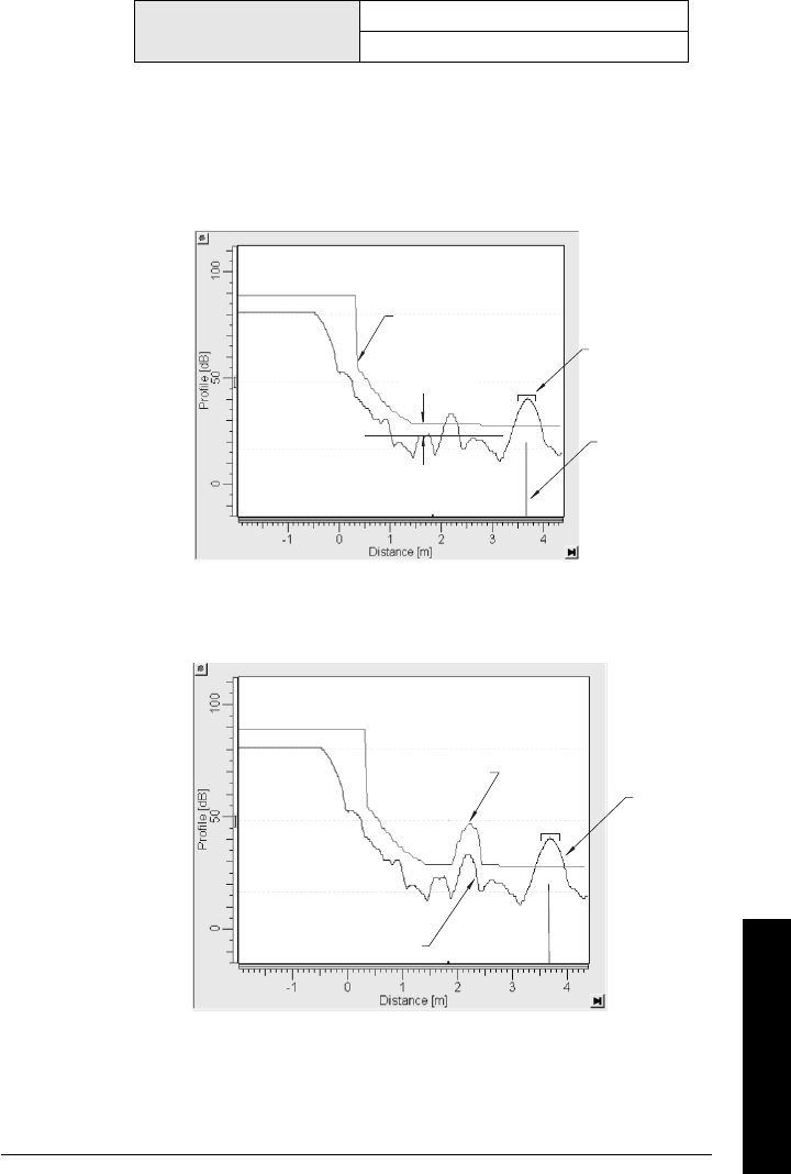
7ML19985JE01 SITRANS LR250 (HART) – INSTRUCTION MANUAL Page 75
mmmmm
Parameters
2.2.5.7. Range (Auto Suppression Range)
Defines the endpoint of the Learned TVT distance. Units are defined in sensor
units.
a. Go to Input > TVT Setup > Range.
b. Determine the actual distance from the antenna reference point to
the material surface.
c. Subtract 0.42 m (16.5") from this distance, and enter the result.
Values Range: 0.00 to 20.00 m
Default: 1.0 0 m
Display before Auto False Echo Suppression
Default
TVT
TVT
Hover Level
Level (db)
Echo
Marker
Window
Example after Auto False Echo Suppression
learned
TVT curve
liquid
level
false echo
Level (db)
false echo
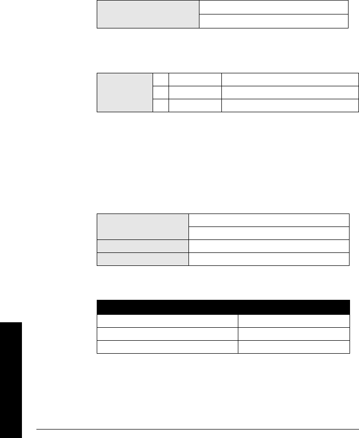
Page 76 SITRANS LR250 (HART) – INSTRUCTION MANUAL 7ML19985JE01
mmmmm
Parameters
2.2.5.8. Shaper Mode
Adjusts the TVT curve at a specified range.
2.2.6. TVT shaper
A breakpoint on the TVT curve, normalized to 0. This parameter is for authorized
Siemens Milltronics service personnel or technicians only.
2.2.6.1. Shaper 1-9
2.2.6.2. Shaper 10-18
2.2.6.3. Shaper 19-27
2.2.6.4. Shaper 28-36
2.2.6.5. Shaper 37-40
2.2.7. Rate
2.2.7.1. Response Rate
Sets the reaction speed of the device to measurement changes in the target range.
Use a setting just faster than the maximum filling or emptying rate (whichever is
greater). Slower settings provide higher accuracy: faster settings allow for more level
fluctuation
2.2.7.2. Fill Rate
Defines the maximum rate at which the reported sensor value is allowed to
increase. Allows you to adjust the SITRANS LR250 response to increases in
the actual material level. Fill Rate is automatically updated whenever
Response Rate is altered.
Enter a value slightly greater than the maximum vessel-filling rate, in Sensor
Units per minute.
Values Range: 0 to 50 dB
Default: 0 dB
Options
*SLOW
0.1 m/minute
MED 1.0 m/minute
FAST 10.0m/minute
Values Range: 0.0000 to 99999 m / min.
Factory setting: 0.1 m/min.
Altered by Response Rate
Related parameters Sensor Units
Options Meters/Minute
Slow 0.1
Medium 1
Fast 10

7ML19985JE01 SITRANS LR250 (HART) – INSTRUCTION MANUAL Page 77
mmmmm
Parameters
2.2.7.3. Empty rate
Defines the maximum rate at which the reported sensor value is allowed to
decrease. Adjusts the SITRANS LR250 response to decreases in the actual
material level. Empty Rate is automatically updated whenever Response Rate
is altered.
Enter a value slightly greater than the vessel’s maximum emptying rate, in
Sensor Units per minute.
2.2.8. Transducer Block (TB) Values (for diagnostic purposes)
2.2.8.1. Reading Measurement
The value for level, or volume (if volume conversion is selected). Read Only.
2.2.8.2. Material Measurement
The value for level. Read Only.
In SIMATIC PDM, open the menu View – Display, and select the tab Display
Level Value panel.
2.2.8.3. Space Measurement
The value for space. Read Only.
In SIMATIC PDM, open the menu View – Display, and select the tab Display
Space Measurement panel.
2.2.8.4. Distance Measurement
The value for distance. Read Only.
In SIMATIC PDM, open the menu View – Display, and select the tab Display
Distance Measurement panel.
2.2.8.5. Volume Measurement
The value for volume. Read Only.
In SIMATIC PDM, open the menu View – Display, and select the tab Display
Volume Measurement panel.
Values Range: 0.0000 to 99999 m / min.
Factory setting: 0.1
Altered by Response Rate
Related Sensor Units
Options Meters/Minute
Slow 0.1
Medium 1
Fast 10

Page 78 SITRANS LR250 (HART) – INSTRUCTION MANUAL 7ML19985JE01
mmmmm
Parameters
2.2.8.6. Sensor Value
The value of the sensor. Read Only.
In SIMATIC PDM, open the menu View – Display, and select the tab Display
Sensor Value.
2.3. Output
2.3.1. mA Output
2.3.1.1. mA Output Value
The loop current value in mA. Read Only except if the Manual option is chosen in
mA Output function below (2.3.1.2).
2.3.1.2. mA Output Function
Alters the mA output/measurement function and allows the output to be set
independently.
Values
User Entry only if Manual option is chosen in
2.3.1.2.
Range: 3.6 mA to 22.6 mA
Options
Manual
*Level
Space
Distance
Volume
Notes:
• The mA Output Function is set independently from the setting in Operation. Set
Operation first and then mA Output Function. (Operation resets mA Output Function
to the same value.)
• The mA Output Function controls the primary value and the loop current for the
STIRANS LR250. Use caution when changing the mA Output function when
connected to a HART network.
• The mA Output Function also affects the secondary, tertiary and quaternary
variables in a HART network.
• mA Output Function must be set to Manual before you can modify the mA Output
Value (2.3.1.1). Remember to restore your previous setting after using mA Output
Function.
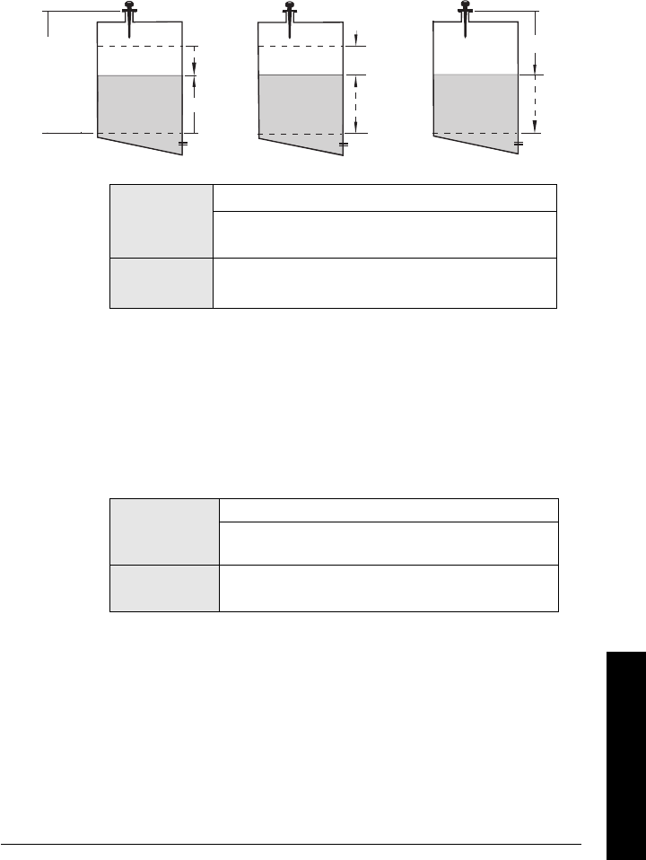
7ML19985JE01 SITRANS LR250 (HART) – INSTRUCTION MANUAL Page 79
mmmmm
Parameters
2.3.1.3. 4 mA Setpoint
Sets the process level corresponding to the 4 mA value. 4 mA always defaults to
0, and mA Output Function determines whether this is a Level, Space, Distance, or
Volume measurement. Level and Space are measured as a percentage of the
difference between High Calibration Point and Low Calibration Point. Distance is
measured as a percentage of the Low Calibration Point.
Enter the reading that is to correspond to a 4 mA output. Units are defined in
Sensor units for Level, Space, or Distance. Units are unspecified for Volume.
2.3.1.4. 20 mA Setpoint
Sets the process level corresponding to the 20 mA value. 20 mA always defaults
to 100%, and mA Output Function determines whether this is a Level, Space, or
Distance measurement. Level and Space are measured as a percentage of the
difference between High Calibration Point and Low Calibration Point: Distance is
measured as a percentage of Low Calibration Point.
Enter the reading that is to correspond to a 20 mA output. Units are defined in
Sensor units for Level, Space, or Distance. Units are unspecified for Volume
.
Values
Range: –99999 to 99999.
Default: 0.000 m (set to value corresponding to 0% as
defined by mA Output Function)
Related
Parameters mA Output Function
Values
Range: –99999 to 99999.
Default: 19.56 m (set to value corresonding to 100%
as defined by mA Output Function)
Related
Parameters mA Output Function
Level Space Distance
Distance
Space
Level
20 mA
100%
0%
4 mA
High Calibration
Point
4 mA
0%
100%
20 mA
4 mA
0%
100%
20 mA
Sensor
reference
point
Low Calibration
Point

Page 80 SITRANS LR250 (HART) – INSTRUCTION MANUAL 7ML19985JE01
mmmmm
Parameters
2.3.1.5. Minimum mA limit
Prevents the mA output from dropping below this minimum level for a
measurement value. This does not restrict the Failsafe or manual settings..
2.3.1.6. Maximum mA limit
Prevents the mA output from rising above this maximum level for a
measurement value. This does not restrict the Failsafe or manual settings.
2.3.1.7. 4 mA Output Trim
Calibrates the 4 mA output. The mA output of the device is pre-calibrated;
however, 4 mA Output Trim can be used to trim remote displays or inputs.
Steps:
1. Set mA Output Function Manual.
2. Set mA Output Value to 4 mA.
3. Attach a calibrated meter and check the output at the terminals; record
the remote reading in mA.
4. Enter this value in 4 mA Output Trim.
5. Restore mA Output Function to previous setting.
6. Confirm that the mA output is as expected.
2.3.1.8. 20 mA Output Trim
Calibrates the 20 mA output. The mA output of the device is pre-calibrated;
however, 20 mA Output Trim can be used to trim remote displays or inputs.
Steps:
1. Set mA Output Function to Manual.
2. Set mA Output Value to 4 mA.
3. Attach a calibrated meter and check the output at the terminals; record
the remote reading in mA.
4. Enter this value in 20 mA Output Trim.
5. Restore mA Output Function to previous setting.
6. Confirm that the mA output is as expected.
Values Range: 3.8 to 20.5 (mA)
Default: 3.8 (mA)
Values Range: 3.8 to 20.5 (mA)
Default: 20.5 (mA)
Values Range: 2.0 to 6.0 (mA)
Related
parameters 20 mA Output Trim
Values Range: 18.0 to 24.0 (mA)
Related
parameters 4 mA Output Trim
7ML19985JE01 SITRANS LR250 (HART) – INSTRUCTION MANUAL Page 81
mmmmm
Parameters
2.4. Failsafe
2.4.1. Failsafe Timers
Sets the time to elapse in minutes since the last valid reading, before Failsafe
State activates
2.4.2. Failsafe Material Level
The material level to be reported when the Failsafe Timer expires.
2.4.3. Failsafe Level
Defines a user-defined level to report when the Failsafe timer expires..
3. Diagnostics
3.1. Echo Profile
Allows you to request the current echo profile either via the handheld programmer,
or via SIMATIC PDM.
To request a profile via SIMATIC PDM:
a. Open the menu View – Echo Profile.
b. If desired, press Save.
c. To view the saved profile, open the menu View – Show Echo Profile.
To request a profile via the handheld programmer:
a. In PROGRAM mode, navigate to LEVEL METER >
DIAGNOSTICS > ECHO PROFILE.
b. Press Right ARROW to request a profile.
Values Range: 0.00 to720 min.
Default: 100.0
Note: The last valid reading is maintained until the Failsafe timer expires. After the
timer expires, the reading is set based on Failsafe Material Level (next page).
Values
HI: Use Maximum mA Limit as material level
LO: Use Minimum mA Limit as material level
*HOLD: Level remains at last reading
VALUE: User-selected value (defined in Failsafe Level
below)
Values Range: 3.6 mA to 22.6 mA
Default: 22.6 mA
Note: Failsafe Material Level must be set to VALUE to use this value.
DIAGNOSTICS
X
3.2
FAULT RESET
MEAS. VALUES
REMAIN DEV. LIFE
ECHO PROFILE
ECHO PROFILE
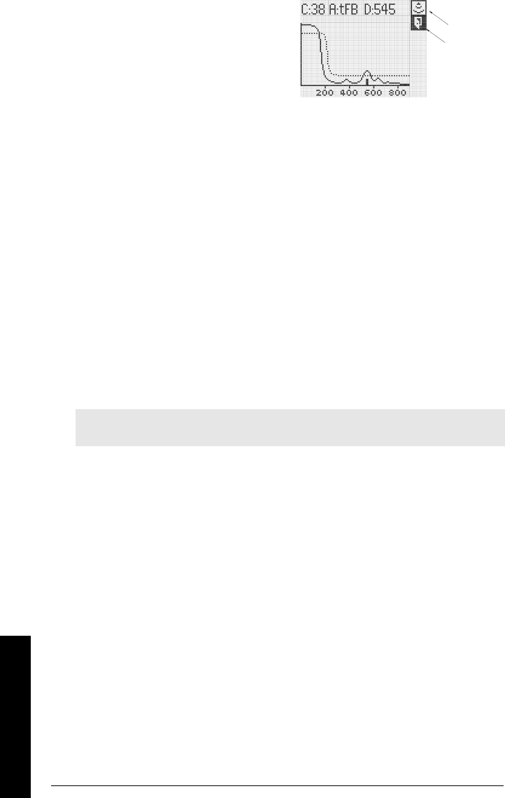
Page 82 SITRANS LR250 (HART) – INSTRUCTION MANUAL 7ML19985JE01
mmmmm
Parameters
c. In the Profile screen, press Up
ARROW to select the Transmit icon,
and Right ARROW to update the
profile.
d. Press Down ARROW to select the
Exit icon, then Right ARROW to
return to previous menu.
3.14. Measured Values
3.14.1. Current Internal Temperature
Read Only. Displays (in degrees C) the current temperature on the circuit board
recorded by the internal electronics.
In SIMATIC PDM, open the menu Diagnostics, and select the tab Measured
Values panel.
3.14.2. Maximum Internal Temperature
Read Only. Displays (in degrees C) the maximum temperature recorded by the
internal electronics. The high and low values are maintained over a power cycle.
In SIMATIC PDM, open the menu Diagnostics, and select the tab Measured
Values panel.
3.14.3. Minimum Internal Temperature
Read Only. Displays (in degrees C) the minimum temperature recorded by the
internal electronics. The high and low values are maintained over a power cycle.
3.15. Remaining Device Lifetime
Use the Remaining Device/Sensor Lifetime parameters to set up schedules for
calibration and maintenance. The device will track itself based on operating hours,
instead of a calendar-based schedule, and will monitor its predicted lifetime.
The maintenance warnings and alarms are communicated to the end user through
status information. This information can be integrated into any Asset Management
system. For optimal use, we recommend that you use SIMATIC PCS7 Asset
Management Software in conjunction with SIMATIC PDM.
The device monitors the predicted lifetime of the device.
3.15.1. Total Device Operating Time
Read only. Displays the amount of time the device has been operating.
3.15.2. Remaining Device Lifetime
Read only. The sum of Total Expected Device Life less Total Device Operating
Time.
Note: Performing a Factory Reset will reset all the Maintenance Schedule parameters
to their factory defaults.
transmit
icon
exit icon

7ML19985JE01 SITRANS LR250 (HART) – INSTRUCTION MANUAL Page 83
mmmmm
Parameters
3.15.3. Maintenance Required Limit
Allows you to set the time period after which an alert will signal that maintenance
is required.
In SIMATIC PDM, open the menu Device – Maintenance, click on Remaining
Device Lifetime.
a) Enable Alert Activation (see 3.15.5 Maintenance Alert Activation for more
detail).
b) Modify values as required. Click Write to accept the changes.
3.15.4. Maintenance Demanded Limit
Allows you to set the time period after which an alert will signal that maintenance
is demanded.
In SIMATIC PDM, open the menu Device – Maintenance, click on Remaining
Device Lifetime.
a) Enable Alert Activation (see 3.15.5 Maintenance Alert Activation for more
detail).
b) Modify values as required. Click Write to accept the changes.
3.15.5. Maintenance Alert Activation
Select limits to be activated.
To enable or disable Maintenance Alert Activation via PDM:
a) Open the menu Device – Maintenance, click on Remaining Device Lifetime.
b) Select either or both of Enable Maintenance Required Alert and Enable
Maintenance Demanded Alert. Click Write to accept the changes.
Values Range: 0 to 20 years
Default: 0.164 years
Values Range: 0 to 20 years
Default: 0.019 years
Values
Warning Limit 1 (Mainteance Required
Limit)
Warning Limit 2 (Maintenance Demanded
Limit)
*OFF
Page 84 SITRANS LR250 (HART) – INSTRUCTION MANUAL 7ML19985JE01
mmmmm
Parameters
3.15.6. Total Expected Device Life
The device tries to predict its overall lifetime. The factory default can be reset by
the user.
To modify the value via PDM, open the menu Device – Maintenance, click on
Remaining Device Lifetime, enter the desired value then click Write to accept it.
3.15.7. Maintenance Status
Read only. Displays the status of the Maintenance Alerts
3.15.8. Acknowledge Status
Read only. Displays the status of the Maintenance Alerts that have been
acknowledged.
3.15.9. Acknowledge
Allows you to acknowledge either a Maintenance Required or a Maintenance
Demanded alert.
To acknowledge an alert via PDM:
a) Open the menu View – Device Status and click on the tab Maintenance.
b) In the Device Lifetime section, modify values as required. Click Write to accept
the changes.
3.16. Remaining Sensor Lifetime
The device monitors the predicted lifetime of the sensor (the components exposed
to the vessel environment).
3.16.1. Total Sensor Operating Time
Read only. Displays the amount of time the sensor has been operating.
3.16.2. Remaining Sensor Lifetime
Read only. The sum of Total Expected Device Life less Total Device Operating Time.
Values Range: 0 to 20 years
Default: 10.07 years
Values
0 No maintenance alerts active
1 Maintenance Required Alert active
2 Maintenance Demanded Alert Active
Values
0 No maintenance alerts acknowledged
1Maintenance Required Alert
acknowledged
2Maintenance Demanded Alert
acknowledged
7ML19985JE01 SITRANS LR250 (HART) – INSTRUCTION MANUAL Page 85
mmmmm
Parameters
3.16.3. Maintenance Required Limit
Allows you to set the time period after which an alert will signal that maintenance
is required.
To modfify the value via PDM, open the menu Device – Maintenance and click on
Remaining Device Lifetime.
a) Enable Alert Activation (see 3.2.1. Maintenance Alert Activation for more
detail).
b) Modify values as required. Click Write to accept the changes.
3.16.4. Maintenance Demanded Limit
Allows you to set the time period after which an alert will signal that maintenance
is demanded.
To modfify the value via PDM, open the menu Device – Maintenance and click on
Remaining Device Lifetime.
a) Enable Alert Activation (see 3.2.1. Maintenance Alert Activation for more
detail).
b) Modify values as required. Click Write to accept the changes.
3.16.5. Maintenance Alert Activation
Select limits to be activated.
To enable or disable Maintenance Alert Activation via PDM:
a) Open the menu Device – Maintenance, and click on Remaining Device
Lifetime.
b) Select either or both of Enable Maintenance Required Alert and Enable
Maintenance Demanded Alert. Click Write to accept the change.
Values Range: 0 to 20 years
Default: 0.164 years
Values Range: 0 to 20 years
Default: 0.019 years
Values
Warning Limit 1 (Mainteance Required
Limit)
Warning Limit 2 (Maintenance Demanded
Limit)
*OFF
Page 86 SITRANS LR250 (HART) – INSTRUCTION MANUAL 7ML19985JE01
mmmmm
Parameters
3.16.6. Total Expected Sensor Life
The device tries to predict its overall lifetime. The factory default can be reset by
the user.
To modify the value via PDM, open the menu Device – Maintenance, click on
Remaining Sensor Lifetime, enter the desired value then click Write.
3.16.7. Maintenance Status
Read only. Displays the status of the Maintenance Alerts
To modfify the value via PDM, open the menu Device – Maintenance and click on
Remaining Device Lifetime.
a) Enable Alert Activation (see 3.2.1. Maintenance Alert Activation for more
detail).
b) Modify values as required. Click Write to accept the changes.
3.16.8. Acknowledge Status
Read only. Displays the status of the Maintenance Alerts that have been
acknowledged.
3.16.9. Acknowledge
Allows you to acknowledge either a Maintenance Required or a Maintenance
Demanded alert.
To acknowledge an alert via PDM:
a) Open the menu View – Device Status and click on the tab Maintenance.
b) In the Device Lifetime section, modify values as required. Click Write to accept
the changes.
Values Range: 0 to 20 years
Default: 10.07 years
Values
0 No maintenance alerts active
1 Maintenance Required Alert active
2 Maintenance Demanded Alert Active
Values
0 No maintenance alerts acknowledged
1Maintenance Required Alert
acknowledged
2Maintenance Demanded Alert
acknowledged

7ML19985JE01 SITRANS LR250 (HART) – INSTRUCTION MANUAL Page 87
mmmmm
Parameters
4. Service
4.1. Factory Reset
Resets all parameters to their factory settings, with the following exceptions:
• the Lock and Unlock values are not reset.
• The learned TVT curve is not lost.
• In Edit Mode, only the Factory Default performs a Factory Reset. The
Idle or Done setting returns you to the previous menu.
To peform a factory reset via SIMATIC PDM, open the menu Device –
Master Reset.
4.2. Powered Hours
Displays the number of hours the unit has been powered up since manufacture.
4.4. Power-on Resets
The number of power cycles that have occurred since manufacture.
4.7. Manufacture Date
The date of manufacture of the SITRANS LR250 (yy mm dd).
4.8. Software Revision
Corresponds to the software or firmware that is embedded in the SITRANS LR250.
4.9. Loader Revision
Corresponds to the software used to update the SITRANS LR250.
4.11. Hardware Revision
Corresponds to the electronics hardware of the SITRANS LR250.
4.12. Memory Test
Allows verification of the RAM, EEPROM, and Flash Memory of the SITRANS LR250.
Press any numeric key to activate the test. The reading will first display buSY,
then the test result text.
Note: Following a Master Reset, complete reprogramming is required.
Options *Idle or Done (Return to previous menu)
Factory Default (Factory Reset Performed)
Values (Read only)
PASS Memory test successful
IdLE No test in progress
buSY Test in progress
FAIL Test failed
Fxxxx Memory address that failed memory test.
Page 88 SITRANS LR250 (HART) – INSTRUCTION MANUAL 7ML19985JE01
mmmmm
Parameters
4.17. Service Interval
Allows for scheduling of service inspections.
4.17.1. Last Time Serviced
Read only. Time elapsed since device was last serviced
4.17.2. Maintenance Required Limit
If the time elapsed from last service is equal to or less than this limit, a Maintenance
Required status is generated.
4.17.3. Maintenance Demanded Limit
If the time elapsed from last service is equal to or less than this limit, a Maintenance
Demaded status is generated.
4.17.4. Alert Activation
Select limits to be activated.
4.17.5. Service Interval
Set time between scheduled service inspections
4.17.6. Maintenance Status
Read only. Displays the status of the Maintenance Alerts
Values Range: 0 to 20 years
Default: 0.164 years
Values Range: 0 to 20 years
Default: 0.019 years
Values
* Timer off
On - no limits
On - limits 1 and 2
On - limit 2
Values Range: 0 to 20 years
Default: 1.0 years
Values
0 No maintenance alerts active
1 Maintenance Required Alert active
2 Maintenance Demanded Alert Active
7ML19985JE01 SITRANS LR250 (HART) – INSTRUCTION MANUAL Page 89
mmmmm
Parameters
4.17.7. Acknowledge Status
Read only. Displays the status of the Maintenance Alerts that have been
acknowledged.
4.17.8. Acknowledge
Allows you to acknowledge either a Maintenance Required or a Maintenance
Demanded alert.
4.18. Calibration Interval
Allows for scheduling of calibrations.
4.18.1. Last Time Calibrated
Read only. Time elapsed since device was last calibrated.
4.18.2. Maintenance Required Limit
If the time elapsed from last calibration is equal to or less than this limit, a
Maintenance Required status is generated.
4.18.3. Maintenance Demanded Limit
If the time elapsed from last calibration is equal to or less than this limit, a
Maintenance Demaded status is generated.
4.18.4. Alert Activation
Select limits to be activated.
Values
0 No maintenance alerts acknowledged
1Maintenance Required Alert
acknowledged
2Maintenance Demanded Alert
acknowledged
Values Range: 0 to 20 years
Default: 0.164 years
Values Range: 0 to 20 years
Default: 0.019 years
Values
* Timer off
On - no limits
On - limits 1 and 2
On - limit 2
Page 90 SITRANS LR250 (HART) – INSTRUCTION MANUAL 7ML19985JE01
mmmmm
Parameters
4.18.5. Total Calibration Interval
Set time between scheduled calibrations.
4.18.6. Maintenance Status
Read only. Displays the status of the Maintenance Alerts
4.18.7. Acknowledge Status
Read only. Displays the status of the Maintenance Alerts that have been
acknowledged.
4.18.8. Acknowledge
Allows you to acknowledge either a Maintenance Required or a Maintenance
Demanded alert.
5. Communication
5.1. Device Address
Sets the device address or poll ID on a HART network. Any address other than 0 will
cause the output current to be a fixed value, and the current will not indicate the
reading.
5.2. Communication Control
Enables the read/write access to parameters via remote communications
Values Range: 0 to 20 years
Default: 1.0 years
Values
0 No maintenance alerts active
1 Maintenance Required Alert active
2 Maintenance Demanded Alert Active
Values
0 No maintenance alerts acknowledged
1Maintenance Required Alert
acknowledged
2Maintenance Demanded Alert
acknowledged
Values Range: 0 to 15
Default: 0
Options
Read Only
*Read Write
Restricted
7ML19985JE01 SITRANS LR250 (HART) – INSTRUCTION MANUAL Page 91
mmmmm
Parameters
6. Security
6.1. Lock
Prevents any changes to parameters via the hand-held programmer.
Note: This lock only applies only to the hand-held programmer: it does not lock
through communcations. A remote master can change configuration if 5.2
Communication Control is set to allow this.
To secure the programming lock: Key in any value other than the unlock value.
Parameters are now locked and cannot be changed.
To unlock the device and enable hand-held programming changes: Key in the
unlock value. Parameters are now unlocked and may be changed.
6.2. Unlock value
Stores the value to enter in Lock (6.1) to unlock programming. If Lock is on, Unlock
Value will not display the unlocked value
Notes:
• Default setting for 6.1 (Lock) is Unlocked.
• After a new value is stored in Unlock Value (6.2), that value will be
recalled after a Factory Reset.
• Consult your Siemens Milltronics representative if you have forgotten
the unlock value.
7. Language
Selects the language to be used on the LCD.
Note: Do not lose this number value.
Hand-held
programmer
Values
1954 (unlock value) Off (enables local programming)
any other value On (disables local programming)
Hand-held
programmer
Values
Range 1 to 9999
Factory Setting 1954
---- Display when Lock is on
Options *English
German
French
Spanish

Page 92 SITRANS LR250 (HART) – INSTRUCTION MANUAL 7ML19985JE01
mmmmm
Parameters

7ML19985JE01 SITRANS LR250 (HART) – INSTRUCTION MANUAL Page 93
mmmmm
A: Parameter List
Appendix A: Alphabetical Parameter
List
Parameter Name/Parameter Number/Page Number
20 mA Output Trim
(2.3.1.8.) on page 80
20 mA Setpoint
(2.3.1.4.) on page 79
4 mA Output Trim
(2.3.1.7.) on page 80
4 mA Setpoint
(2.3.1.3.) on page 79
Algorithm
(2.2.4.1.1.) on page 71
Antenna
(2.2.1.1.) on pag e 63
Auto False Echo Suppression
(2.2.5.6.) on page 74
Communication Control
(5.2.) on page 90
Confidence
(2.2.4.5.1.) on page 73
Current Internal Temperature
(3.14.1.) on page 82
Damping Filter
(2.2.4.3.3.) on page 73
Dimension A
(2.2.3.2.) on page 69
Dimension L
(2.2.3.3.) on page 69
Distance Measurement
(2.2.8.4.) on page 77
Echo Lock
(2.2.4.2.1.) on page 72
Echo Threshold
(2.2.4.1.3.) on page 71
Empty rate
(2.2.7.3.) on page 77
Factory Reset
(4.1.) on page 87
Failsafe Level
(2.4.3.) on page 81
Failsafe Material Level
(2.4.2.) on page 81
Failsafe Timers
(2.4.1.) on page 81
Far Range
(2.2.1.13.) on page 66
Fill Rate
(2.2.7.2.) on page 76
High Calibration Pt.
(2.2.1.7.) on page 66
Language
(7.) on page 91
Level Offset
(2 .2.1.15. ) on pag e 67
Lock
(6.1.) on page 91
Low Calibration Pt.
(2.2.1.6.) on page 65
mA Output Function
(2.3.1.2.) on page 78
mA Output Value
(2. 3.1.1. ) on p age 78

Page 94 SITRANS LR250 (HART) – INSTRUCTION MANUAL 7ML19985JE01
mmmmm
A: Parameter List
Material Measurement
(2.2.8.2.) on page 77
Maximum mA limit
(2.3.1.6.) on page 80
Maximum Volume
(2.2.3.1.) on page 69
Memory Test
(4.12.) on page 87
Minimum mA limit
(2.3.1.5.) on page 80
Near Range
(2.2.1.12.) on page 66
Noise
(2.2.4.5.) on page 73
Operation
(2.2.1.5.) on page 65
Position
(2.2.4.1.2.) on page 71
Powered Hours
(4.2.) on page 87
Power-on Resets
(4.4.) on page 87
Propagation Factor
(2 . 2.1.14. ) on p ag e 66
Range (Auto Suppression Range)
(2.2.5.7.) on page 75
Reading Measurement
(2.2.8.1.) on page 77
Response Rate
(2.2.7.1.) on page 76
Sampling up
(2.2.4.2.4.) on page 72/
Sampling down1
(2.2.4.2.5.) on page 72
Sensor Units
(2.2.1.4.) on page 64
Software Revision
(4.8.) on page 87
Space Measurement
(2.2.8.3.) on page 77
Strength
(2.2.4.5.2.) on page 73
TVT Hover Level
(2.2.5.1.) on page 74
Unlock value
(6.2.) on page 91
Vessel Shape
(2.2.2.1.) on page 67
Volume Breakpoints
(2.2.3.) on page 69
Volume Breakpoints
(2.2.3.) on page 69
Volume Measurement
(2.2.8.5.) on page 77
Window1
(2.2.4.2.6.) on page 72
Parameter Name/Parameter Number/Page Number

7ML19985JE01 SITRANS LR250 (HART) – INSTRUCTION MANUAL Page 95
mmmmm
B: Programming Chart
Appendix B: Programming Chart
Parameter Number and Name Value
20 mA Output Trim
(2.3.1.8.)
20 mA Setpoint
(2.3.1.4.)
4 mA Output Trim
(2.3.1.7.)
4 mA Setpoint
(2.3.1.3.)
Algorithm
(2 .2.4 .1.1.)
Antenna
(2 . 2.1.1. )
Auto False Echo Suppression
(2.2.5.6.)
Communication Control
(5.2.)
Confidence
(2.2.4.5.1.)
Current Internal Temperature
(3.14.1.)
Damping Filter
(2.2.4.3.3.)
Dimension L
(2.2.3.3.)
Distance Measurement
(2.2.8.4.)
Echo Lock
(2.2.4.2.1.)
Echo Threshold
(2.2.4.1.3.)
Empty rate
(2.2.7.3.)
Factory Reset
(4.1.)
Failsafe Level
(2.4.3.)
Failsafe Material Level
(2.4.2.)
Failsafe Timers
(2.4.1.)
Far Range
(2 . 2.1.13. )
Fill Rate
(2.2.7.2.)
High Calibration Pt.
(2.2.1.7.)
Language
(7.)
Level Offset
(2.2.1.15.)
Lock
(6.1.)
Low Calibration Pt.
(2.2.1.6.)
mA Output Function
(2.3.1.2.)
mA Output Value
(2.3.1.1.)
Material Measurement
(2.2.8.2.)
Maximum mA limit
(2.3.1.6.)
Maximum Volume
(2.2.3.1.)

Page 96 SITRANS LR250 (HART) – INSTRUCTION MANUAL 7ML19985JE01
mmmmm
B: Programming Chart
Memory Test
(4.12.)
Minimum mA limit
(2.3.1.5.)
Near Range
(2.2.1.12.)
Noise
(2.2.4.5.)
Operation
(2.2.1.5.)
Position
(2.2.4.1.2.)
Powered Hours
(4.2.)
Power-on Resets
(4.4.)
Propagation Factor
(2.2.1.14.)
Range (Auto Suppression Range)
(2.2.5.7.)
Reading Measurement
(2.2.8.1.)
Response Rate
(2.2.7.1.)
Sampling up
(2.2.4.2.4.)/
Sampling down1
(2.2.4.2.5.)
Sensor Units
(2.2.1.4.)
Software Revision
(4.8.)
Space Measurement
(2.2.8.3.)
Strength
(2.2.4.5.2.)
TVT Hover Level
(2.2.5.1.)
Unlock value
(6.2.)
Vessel Shape
(2.2.2.1.)
Volume Breakpoints
(2.2.3.)
Volume Measurement
(2.2.8.5.)
Window1
(2.2.4.2.6.)
Parameter Number and Name (Continued) Value

7ML19985JE01 SITRANS LR250 (HART) – INSTRUCTION MANUAL Page 97
mmmmm
C: Troubleshooting
Appendix C: Troubleshooting
Communication Troubleshooting
Generally:
1. Check the following:
• There is power at the instrument
• The LCD shows the relevant data
• The device can be programmed using the hand programmer
2. Verify that the wiring connections are correct.
3. If you continue to experience problems, go to our website at:
. www.siemens.com/processautomation, and check the FAQs for SITRANS LR250, or
contact your local Siemens Milltronics representative.
Specifically:
1. If you try to set a SITRANS LR250 parameter via remote communications, but the
parameter remains unchanged:
• Some parameters can only be changed when the device is not scanning. Try
putting the device in PROGRAM mode using the operating mode function.
• Try setting the parameter from the keypad. (First make sure that the lock
parameter [6.1] is set to the unlock value.)
• The communications control parameter 5.2 must be set to 1 to allow you to write
parameters to SITRANS LR250.
2. If you see unanticipated displays, for example:
• PROGRAM mode displayed instead of Measurement mode
• the wrong parameter displayed in response to a command
• a parameter displayed in response to no command
make sure no infrared-capable device is close to SITRANS LR250. Any device with
infrared capabilities (laptops, cell phones, PDAs) can cause interference which
simulates a command to the SITRANS LR250, potentially causing it to switch modes
or to change a parameter.
3. If the operation is erratic, make sure the Hand Programmer is not being used at the
same time as SIMATIC PDM.

Page 98 SITRANS LR250 (HART) – INSTRUCTION MANUAL 7ML19985JE01
mmmmm
C: Troubleshooting
General Fault Codes
Fault Codes
Notes:
• Some faults cause the device to go to Failsafe mode (Fault 52). These are indicated with
an asterisk (*).
Fault Codes
Code Meaning Corrective Action
S:0 * The device was unable to get a
measurement within the Failsafe Timer
period. Possible causes: faulty
installation, antenna buildup, foaming/
other adverse process conditions, invalid
calibration range.
Ensure installation details are correct.
Ensure no antenna buildup. Adjust
process conditions to minimize foam or
other adverse conditions. Correct
range calibration. If fault persists,
contact your local Siemens
representative.
S:2 *The device is operating in a low power
condition that is outside its operating
range. As a result, a valid measurement
has not been taken for the failsafe timer
period, and the device will be put into
failsafe mode.
Correct the power supply (resistance
or voltage).
S:3 Device is nearing its lifetime limit
according to the value set in
Maintenance Required Limit.
Replacement is recommended.
S:4 Device is nearing its lifetime limit
according to the value set in
Maintenance Demanded Limit.
Replacement is recommended.
S:6 Sensor is nearing its lifetime limit
according to the value set in
Maintenance Required Limit.
Replacement is recommended.
S:7 Sensor is nearing its lifetime limit
according to the value set in
Maintenance Demanded Limit.
Replacement is recommended.

7ML19985JE01 SITRANS LR250 (HART) – INSTRUCTION MANUAL Page 99
mmmmm
C: Troubleshooting
S:8 Service interval as defined in
Maintenance Required Limit has expired.
Perform service.
S:9 Service interval as defined in
Maintenance Demanded Limit has
expired.
Perform service.
S:11 Internal temperature sensor failure. Repair required: contact your local
Siemens representative.
S:12 Internal temperature of device has
exceeded specifications: it is operating
outside its temperature range.
Relocate device and/or lower process
temperature enough to cool device.
Inspect for heat-related damage and
contact your local Siemens
representative if repair is required.
S:17 Calibration interval as defined in
Maintenance Required Limit has expired.
Perform calibration.
S:18 Calibration interval as defined in
Maintenance Demanded Limit has
expired.
Perform calibration.
S:28 * Internal device failure caused by a RAM
memory error.
Repair required: contact your local
Siemens representative.
S:29 *EEPROM damaged. Repair required: contact your local
Siemens representative.
S:31 * Flash error. Repair required: contact your local
Siemens representative.
S:33 *Factory calibration for the internal
temperature sensor has been lost.
Repair required: contact your local
Siemens representative.
S:34 * Factory calibration for the device has
been lost.
Repair required: contact your local
Siemens representative.
S:35 *Factory calibration for the device has
been lost.
Repair required: contact your local
Siemens representative.
S:36 * Unable to start microwave module. Reset power. If error persists, contact
your local Siemens representative.
Fault Codes (cont’d)
Code Meaning Corrective Action

Page 100 SITRANS LR250 (HART) – INSTRUCTION MANUAL 7ML19985JE01
mmmmm
C: Troubleshooting
S:37 *Measurement hardware problem. Reset power. If error persists, contact
your local Siemens representative.
S:38 * Failure in the device electronics. Reset power. If fault persists, contact
your local Siemens representative:
repair required.
S:43 *Factory calibration for the radar receiver
has been lost.
Repair required: contact your local
Siemens representative.
S:44 * Factory calibration for the echo slope has
been lost.
Repair required: contact your local
Siemens representative.
S:45 *No valid boot program detected:
firmware corrupt.
Repair required: contact your local
Siemens representative.
S:48 * User configuration is invalid. One or more
of parameters: Low Calibration Point,
High Calibration Point, Volume
breakpoints, and/or Auto False-Echo
Suppression, are set to invalid values.
Reconfigure the unit. Ensure the
difference between High Calibration
Point and Low Calibration Point is not
less than zero; check the breakpoints
(only required if
2.2.3. Volume
Breakpoints
is not set to 0).
S:49 *EEPROM corrupt. Repair required: contact your local
Siemens representative.
S:50 * EEPROM corrupt. Repair required: contact your local
Siemens representative.
S:51 *EEPROM corrupt. Repair required: contact your local
Siemens representative.
S:52 Failsafe is activated. Possible causes: 1)
hardware failure; 2) memory failure;
3)Fault 48; 4) failsafe timer expired–
possible causes: faulty installation,
antenna buildup, foaming/other adverse
process conditions, invalid calibration
range.
For 3) and 4) Correct configuration;
ensure installation is correct; no
antenna buildup; adjust process
conditions to minimize foaming/other
adverse conditions; correct calibration
range. If fault persists, or for 1) and 2),
contact your local Siemens
representative.
S:53 *Configuration lost: one or more
parameter settings have been lost. This
may occur after a firmware upgrade
causes user parameters to be reset.
Restore user parameters using
SIMATIC PDM.
Fault Codes (cont’d)
Code Meaning Corrective Action
7ML19985JE01 SITRANS LR250 (HART) – INSTRUCTION MANUAL Page 101
mmmmm
C: Troubleshooting
Operation Troubleshooting
Operating symptoms, probable causes, and resolutions.
Symptom Cause Action
Display flashes
LOE and status
symbol shows
level or target is out of range • check specifications
• check
2.2.1.6. Low Calibration
Pt.
• increase
2.2.4.5.1. Confidence
Display flashes
LOE and status
symbol shows
material build-up on antenna • clean the antenna
• re-locate SITRANS LR250
Display flashes
LOE and status
symbol shows
location or aiming:
• poor installation
• flange not level
• check to ensure nozzle is
vertical
•use
2.2.5.6. Auto False Echo
Suppression
and check
2.2.5.7.
Range (Auto Suppression
Range)
to ensure nozzle
protrudes from end of nozzle.
Display flashes
LOE and status
symbol shows
antenna malfunction:
• temperature too high
• physical damage
• excessive foam
• multiple echoes
• check
3.14.1. Current Internal
Temperature
• use foam deflector or stilling
well
•relocate
• use a defoamer
• set
2.2.4.1.1. Algorithm
to F
(First echo)

Page 102 SITRANS LR250 (HART) – INSTRUCTION MANUAL 7ML19985JE01
mmmmm
C: Troubleshooting
Reading does
not change, but
the level does
SITRANS LR250 processing
wrong echo, i.e. vessel wall, or
structural member
• re-locate SITRANS LR250
• check nozzle for internal burrs
or welds
• rotate instrument 90°
•use
2.2.5.6. Auto False Echo
Suppression
and
2.2.5.7.
Range (Auto Suppression
Range)
Measurement is
consistently off
by a constant
amount
• setting for
2.2.1.6. Low
Calibration Pt.
not correct
• setting for
2.2.1.15. Level
Offset
not correct
• check distance from flange
face to
2.2.1.6. Low Calibration
Pt.
• check
2.2.1.15. Level Offset
or
device tag
Screen blank
power error • check nameplate rating
against voltage supply
• check power wiring or source
too much load resistance • change barrier type, or
• remove something from the
loop, or
• increase supply voltage
Reading erratic
echo confidence weak • refer to
2.2.4.5.1. Confidence
•use
2.2.5.6. Auto False Echo
Suppression
and
2.2.5.7.
Range (Auto Suppression
Range)
• use foam deflector or stilling
well
liquid surface vortexed • decrease
2.2.7.1. Response
Rate
• relocate instrument to side
pipe
• increase confidence threshold
in
2.2.4.1.3. Echo Threshold
material filling • re-locate SITRANS LR250
Reading
response slow
2.2.7.1. Response Rate
setting
incorrect
• increase measurement
response if possible
Symptom Cause Action (cont’d)

7ML19985JE01 SITRANS LR250 (HART) – INSTRUCTION MANUAL Page 103
mmmmm
C: Troubleshooting
Reads correctly
but occasionally
reads high
when vessel is
not full
• detecting close range echo
• build up near top of vessel or
nozzle
• nozzle problem
• clean the antenna
•use
2.2.5.6. Auto False Echo
Suppression
and
2.2.5.7.
Range (Auto Suppression
Range)
Level reading
lower than
material level
• material is within near
blanking zone
• vessel near empty and low
εr material
• multiple echoes processed
• decrease
2.2.1.12. Near Range
(minimum value depends on
antenna type)
• raise SITRANS LR250
•ensure
2.2.4.1.1. Algorithm
is set
to F (First echo)
• nozzle too narrow for length • see
Rod Extension
Requirements
on page 114.
Symptom Cause Action (cont’d)

Page 104 SITRANS LR250 (HART) – INSTRUCTION MANUAL 7ML19985JE01
mmmmm
D: Maintenance
Appendix D: Maintenance
SITRANS LR250 requires no maintenance or cleaning under normal operating conditions.
Under severe operating conditions, the horn antenna may require periodic cleaning. If
cleaning becomes necessary:
• Note the antenna material and the process medium, and select a cleaning
solution that will not react adversely with either.
• Remove the instrument from service and wipe the antenna clean using a cloth
and suitable cleaning solution.
Unit Repair and Excluded Liability
All changes and repairs must be done by qualified personnel, and applicable safety
regulations must be followed. Please note the following:
• The user is responsible for all changes and repairs made to the device.
• All new components must be provided by Siemens Milltronics Process Instruments Inc.
• Restrict repair to faulty components only.
• Do not re-use faulty components.

7ML19985JE01 SITRANS LR250 (HART) – INSTRUCTION MANUAL Page 105
mmmmm
E: Technical Reference
Appendix E: Technical Reference
Principles of Operation
SITRANS LR250 is a sophisticated radar instrument that uses advanced microwave pulse
technology1 to provide non-contacting continuous level measurement in liquids or
slurries. Radar level measurement uses the time of flight principle to determine distance
to a material surface. The device transmits a signal and waits for the return echo. The
transit time is directly proportional to the distance from the material.
Pulse radar uses polarized electromagnetic waves. Microwave pulses are emitted from
the antenna at a fixed repetition rate, and reflect off the interface between two materials
with different dielectric constants (the atmosphere and the material being monitored).
The echo is detected by a receiver, and the transit time is used to calculate level.
Electromagnetic wave propagation is virtually unaffected by temperature or pressure
changes, or by changes in the vapor levels inside a vessel. Electromagnetic waves are
not attenuated by dust.
SITRANS LR250 consists of an enclosed electronic circuit coupled to an antenna and
process connection. The electronic component generates a radar signal (26 GHz) that is
directed to the horn.
The signal is emitted from the horn, and the reflected echoes are digitally converted to an
echo profile. The profile is analyzed to determine the distance from the material surface
to the reference point on the instrument. This distance is used as a basis for the display of
material level and mA output.
Echo Processing
The three echo processing parameters, Response Rate, Near Range, and Position, are
set to default values shown in the table below. Further information can be found in
Parameter Reference
on the pages shown.
The device characterizes all echoes that rise above the TVT (Time Varying Threshold) as
potential good echoes. Each peak is assigned a rating based on its strength, area, height
above the TVT, amongst other characteristics.
The true echo is selected based on the algorithm selected in
2.2.4.1. Echo select
. Options
are Largest Echo, best of Largest and First, or First.
1. The microwave output level is significantly less than that emitted from cellular phones.
Echo Processing
Parameters
Default
values Description page
2.2.1.3. Response Rate
Fast measurement response to level change 64
2.2.1.12. Near Range
0 user-defined blanking 66
2.2.4.1.2. Position
Hybrid Defines where on the echo the distance
measurement is determined.
71
Page 106 SITRANS LR250 (HART) – INSTRUCTION MANUAL 7ML19985JE01
mmmmm
E: Technical Reference
The echo location algorithm calculates the precise time of flight of that echo, and
calculates the range using the calibrated propagation velocity (adjusted using a
propagation factor, if necessary).
Measurement Response
The measurement response (response rate) limits the maximum rate at which the
display and output respond to changes in the measurement. Once the real process fill/
empty rate (m/s) is established, a response rate can be selected that is slightly higher
than the application rate. The response rate automatically adjusts the filters that affect
the output response rate.
There are three preset options: slow, medium, and fast.
The measurement response limits the maximum rate at which the display and analog
output respond to changes in measurement. Response Rate 2.2.7.1 should be set to a
measurement response just faster than the maximum filling or emptying rate (whichever
is greater).
When the echoes are received, the relevant echo algorithm (2.2.4.1.1) is applied to
determine the true material echo.
Typical Receiver Signal
2.2.7.1.
Response
Rate
2.2.7.2. Fill
Rate
/
2.2.7.3.
Empty rate
2.2.4.2.1.
Echo Lock
2.4.1. Failsafe
Timers
(time in
minutes)
Typical
Update Time
Slow * 0.1 m/min 2 100 ###
Medium 1 m/min 2 10 ###
Fast 10 m/min 2 1 1 sec.
2.2.1.11
Near Range
Empty
Level
End of
Transmit
Range Extension
(2. 2 .1.12) a s %
Difference between High Calibration Point and Low
Calibration Point
7ML19985JE01 SITRANS LR250 (HART) – INSTRUCTION MANUAL Page 107
mmmmm
E: Technical Reference
Echo Lock
When the echoes are received, the relevant echo algorithm is applied to determine the
true material echo. If the selected echo is within the window, the window is then
centered about the echo. Otherwise the window widens with each successive shot until
the selected echo is within the window, which then returns to its normal width.
Echo Lock selects the measurement verification process:
• When Echo Lock is Off, SITRANS LR 250 responds immediately to a new
measurement (within the restrictions set by the Maximum Fill / Empty Rate).
However, measurement reliability is affected.
• When Maximum Verification or Material Agitator is selected, a new measurement
outside the Echo Lock Window must meet the sampling criteria.
• When Total Lock is selected, Echo Lock Window is pre-set to 0, and the window is
automatically calculated after each measurement.
Loss of Echo (LOE)
A loss of echo (LOE) occurs when the calculated measurement is judged to be unreliable
because the echo confidence value has dropped below the echo confidence threshold.
If the LOE condition persists beyond the time limit set in
2.4.1. Failsafe Timers
the LCD
displays the Service Required icon, a wrench accompanied by three dots and the
text region displays the fault code S: 0 and the text LOE.
Fail-safe Mode
Fail-safe Timers
2.4.1. Failsafe Timers
determines the time to elapse after the last valid reading before a
Fail-safe state is activated.
2.4.2. Failsafe Material Level
determines the level to be
reported when the Fail-safe timer expires. Upon receiving a reliable echo, the loss of
echo condition is aborted, the Service Required icon and error message are cleared, and
the reading and mA output return to the current level.
Fail-safe value
When the
2.4.1. Failsafe Timers
expires, the material level to be reported is determined by
2.4.2. Failsafe Material Level
.
Values
0Off
1Maximum Verification
2*
Material Agitator
3Tot al Lock
Fail-safe Material Level
HI Use Maximum mA Limit as material level
LO Use Minimum mA Limit as material level
HOLD Level remains at last reading
VALUE User-selected value

Page 108 SITRANS LR250 (HART) – INSTRUCTION MANUAL 7ML19985JE01
mmmmm
E: Technical Reference
Far Range (Range Extension)
In applications where the base of the vessel is conical or parabolic, a reliable echo may
be available below the vessel empty distance, due to an indirect reflection path.
Increasing the range extension to 30% or 40% can provide stable empty vessel readings.
False-Echo Suppression
False echoes can appear during the receive cycle. They are often created by internal
impediments like a ladder rung, and are usually indicated by an incorrect high level
reading.
Near Range (Blanking)
2.2.1.12. Near Range
programs SITRANS LR250 to ignore the zone in front of the antenna.
The default blanking distance is 0.50 mm from end of horn antenna..
Near Range allows you to increase the blanking value from its factory setting. But
2.2.5.6.
Auto False Echo Suppression
is generally recommended in preference to extending the
blanking distance from factory values.
Auto False-Echo Suppression
The TVT adjustment parameters allow you to set a TVT (Time Varying Threshold) curve, so
that SITRANS LR250 will ignore false echoes.
The default TVT curve hovers above the echo profile, and effectively screens out small
false echoes. But if an obstruction is causing a large echo before the material level echo,
that echo will rise above the default TVT curve. You can use Auto False-Echo Suppression
to filter it out. If possible, rotate the instrument before using Auto False-Echo
Suppression, to lower the amplitude of false echoes.
When you set 2.2.5.6 to Learn, the instrument learns the echo profile at that moment1.
Then it uses the learned profile instead of the default TVT curve, for the distance set in
2.2.5.7. The learned profile (Learned TVT curve) follows the echo profile, so that no large
false echoes rise above the learned TVT curve. From the end of the Auto False-Echo
Suppression Distance, the default TVT curve is used. The material level echo rises above
this, and is selected as the true echo.
For examples, see
Display before Auto False Echo Suppression
on page 109 and
Example
after Auto False Echo Suppression
on page 109.
1. Set 2.2.5.6 to ’Learn’ when the material level is substantially lower than process full level (ideally
when the tank is empty or almost empty).
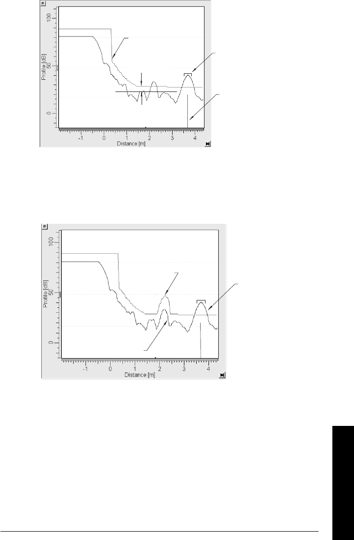
7ML19985JE01 SITRANS LR250 (HART) – INSTRUCTION MANUAL Page 109
mmmmm
E: Technical Reference
Display before Auto False Echo Suppression
Default
TVT
TVT
Hover Level
Level (db)
Echo
Marker
Window
Example after Auto False Echo Suppression
learned
TVT curve
liquid
level
false echo
Level (db)
false echo
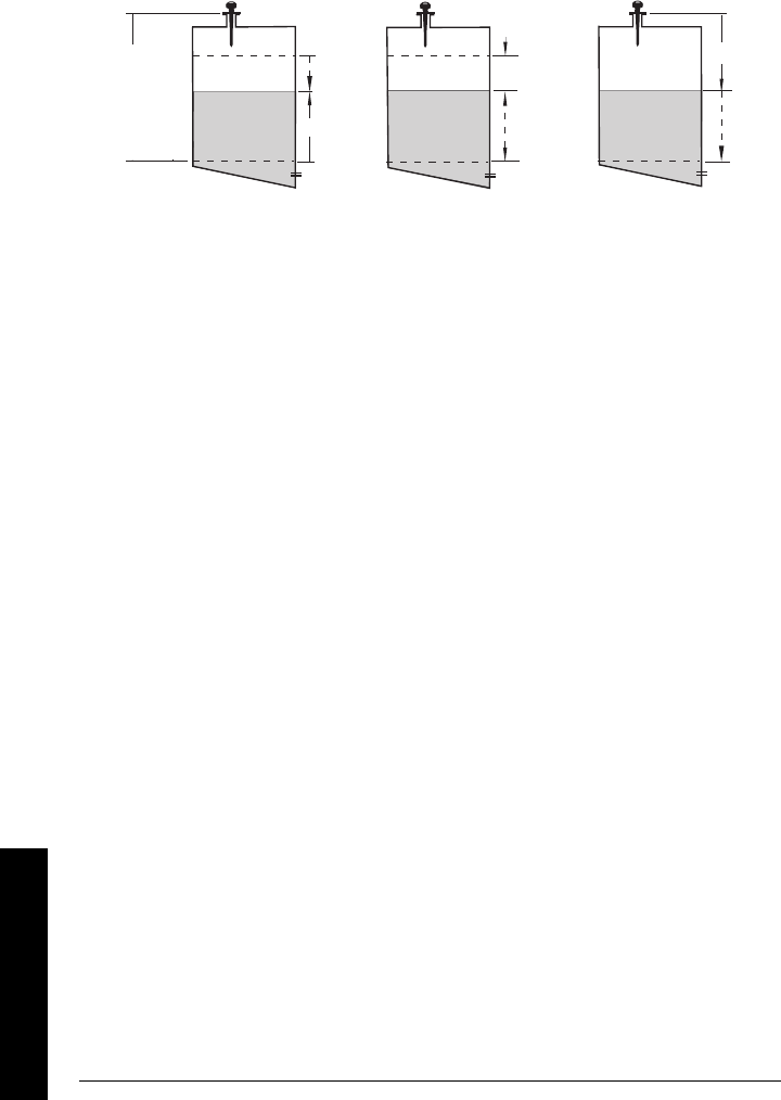
Page 110 SITRANS LR250 (HART) – INSTRUCTION MANUAL 7ML19985JE01
mmmmm
E: Technical Reference
mA Output
The mA output is proportional to the level, in the range 4 to 20 mA. Generally, the output is
set so that the output for 0% is 4 mA, and the output for 100% is 20 mA. 0 and 100% are
percentages of the full-scale reading (m, cm, mm, ft, in).
When SITRANS LR250 is put into PROGRAM mode it stops responding to the process. It
stores the most recent measurement, and holds the associated readings and mA signal
output. The instrument reverts to the parameter last addressed during the previous
program session.
When the instrument is returned to Measurement mode, the transceiver resumes
operation. The reading and mA output default to the last measurement taken. The reading
and associated outputs migrate to the current process level at a rate controlled by the
response rate (2.2.7.1).
If SITRANS LR250 is left in PROGRAM
mode for 10 minutes without input, it automatically
reverts to Measurement mode.
Level Space Distance
Distance
Space
Level
20 mA
100%
0%
4 mA
High Calibration
Point
4 mA
0%
100%
20 mA
4 mA
0%
100%
20 mA
Sensor
reference
point
Low Calibration
Point
7ML19985JE01 SITRANS LR250 (HART) – INSTRUCTION MANUAL Page 111
mmmmm
E: Technical Reference
Maximum Process Temperature Chart
.
Where the chart does not apply, please use your own judgement regarding the use of
SITRANS LR250. Parameter 3.14.1 is required to monitor the Internal Temperature. It gives you an
excellent indication of how reliably the product will perform thermally when installed on your
process vessel.
3.14.1 also allows you to decide whether or not attention should be focussed on
redesigning the installation. For example, if the internal temperature exceeds the
maximum allowable limit, a sun shield or a longer nozzle may be required. Engineering will
use this temperature reading (3.14.1) to gauge the extent of change required to the
installation in order to provide a reliable thermal-operating zone for the SITRANS LR250.
Note: The chart below is for guidance only:
WARNING: Internal temperature must not exceed 80 °C (176 °F).
Maximum Flange and Process Temperatures versus Allowable Ambient for
Polypropylene Rod or Flange Adapter versions of SITRANS LR250
flange
temperature
process
temperature
Ambient Temperature (oC)
Process Flange Surface Temperature (oC)
polypropylene
rod
temperature
(no flange)
Graphic to be revised if required.
• The chart does not represent every
possible process connection
arrangement. For example, it will
NOT apply if you are mounting
SITRANS LR250 on a nozzle greater
than 8” nominal, or directly on a
metallic vessel surface.
• The chart does not take into
consideration heating from direct
sunshine exposure.
ambient
temperature
process
temperature
internal
enclosure
temperature

Page 112 SITRANS LR250 (HART) – INSTRUCTION MANUAL 7ML19985JE01
mmmmm
E: Technical Reference
Process Pressure/Temperature derating
curves1
Notes:
• These configurations are subject to revision: other options may be added.
• Process configuration numbers are not final.
• The Process Device Tag shall remain with the process pressure boundary
assembly1. In the event the instrument package is replaced, the Process Device Tag
shall be transferred to the replacement unit.
• SITRANS LR 250 units are hydrostatically tested, meeting or exceeding the
requirements of the ASME Boiler and Pressure Vessel Code and the European
Pressure Equipment Directive.
• The serial numbers stamped in each process connection body, (flange, threaded, or
sanitary), provide a unique identification number indicating date of manufacture.
Example: MMDDYY – XXX (where MM = month, DD = day, YY = year, and
XXX= sequential unit produced
Further markings (space permitting) indicate flange configuration, size, pressure
class, material, and material heat code.
WARNINGS:
• Never attempt to loosen, remove or disassemble process connection
or instrument housing while vessel contents are under pressure.
• This product is designated as a Pressure Accessory per Directive 97/ 23 / EC
and is not intended for use as a safety device.
• Materials of construction are chosen based on their chemical
compatibility (or inertness) for general purposes. For exposure to
specific environments, check with chemical compatibility charts
before installing.
• The user is responsible for the selection of bolting and gasket
materials which will fall within the limits of the flange and its intended
use and which are suitable for the service conditions.
•Improper installation may result in loss of process pressure and/or
release of process fluids and/or gases.
1. The process pressure boundary assembly comprises the components that act as a barrier
against pressure loss from the process vessel: that is, the combination of process connection
body and emitter, but normally excluding the electrical enclosure.
7ML19985JE01 SITRANS LR250 (HART) – INSTRUCTION MANUAL Page 113
mmmmm
E: Technical Reference
Horn Antenna or Wave Guide – ANSI Hole Pattern, 150#1
Horn Antenna or Wave Guide DN Hole Pattern, PN162
1. Customer to provide adequate bolting and flat-faced gasket to retain vessel pressure and pro-
vide sufficient sealing.
WARNING: Never attempt to loosen, remove or disassemble process
connection or instrument housing while vessel contents are under
pressure.
2. Customer to provide adequate bolting and flat-faced gasket to retain vessel pressure and pro-
vide sufficient sealing.
Process Connection Series:
•51242 to 51???, and 512xx to
512xx, with 25546 and 255xx
series flange.
•Ensure your instrument has
the process identification tag
showing one of this series, and
25546 or 255xx stamped on
flange.
•Reference drawing number is
shown on the process device
tag. You can find this drawing
on our website:
www.siemens.com/
processautomation on the
LR 250 product page, under
Process Connection
Specifications.
process temperature (°C)
pressure (bar, gauge)
4”
6”
3”
8”
50
2.0
4.0
6.0
8.0
10.0
12.0
14.0
16.0
18.0
0
-50 100 150 200
Process Connection Series:
• 51242 to ????, and 512xx to
51512xx with 25547 and 255xx
series flange.
• Ensure your instrument has
the process identification tag
showing one of this series,
and 25547 or 255xx stamped
on flange.
• Reference drawing number is
shown on the process device
tag. You can find this drawing
on our website:
www.siemens.com/
processautomation on the
LR 250 product page, under
Process Connection
Specifications.
process temperature (°C)
100 mm
150 mm 200 mm
80 mm
pressure (bar, gauge)
DETAILS TO BE UPDATED
Page 114 SITRANS LR250 (HART) – INSTRUCTION MANUAL 7ML19985JE01
mmmmm
Appendix F: Loop Power
Appendix F: Loop power
Typical Connection Drawing
Allowable operating area of SITRANS LR250
Curve 1 (General Purpose, Intrinsically Safe, Non-incendive)
Note: Loop voltage is the voltage at the terminals of the power supply (not the
voltage at the terminals of the device).
+
-
LR250
loop resistance
RL
loop current IL
loop voltage
VL
power
supply
Loop Voltage versus Loop Resistance
Power Supply Requirements
0
100
200
300
400
500
600
700
800
900
1000
10.00 15.00 20.00 25.00 30.00
Loop Voltage-VL
Loop Resistance - RL
RL=44.6*VL - 493.4
RL=272.7*VL - 4554.1
(16.7v, 0 ohms)
(17.8v, 300 ohms)
(30.0v,845 ohms)
ALLOWABLE OPERATING
AREA
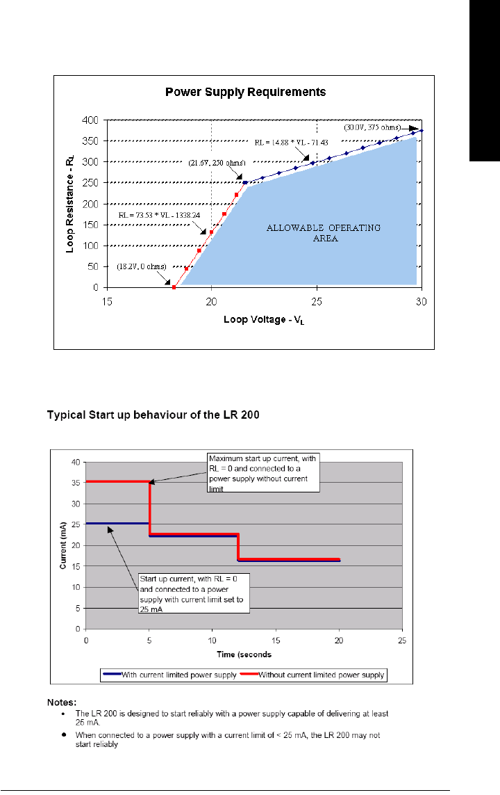
7ML19985JE01 SITRANS LR250 (HART) – INSTRUCTION MANUAL Page 115
mmmmm
Appendix F: Loop Power
Curve 2 (Flameproof, Increased Safety, Explosion-proof)
Startup Curve
Loop Voltage versus Loop Resistance
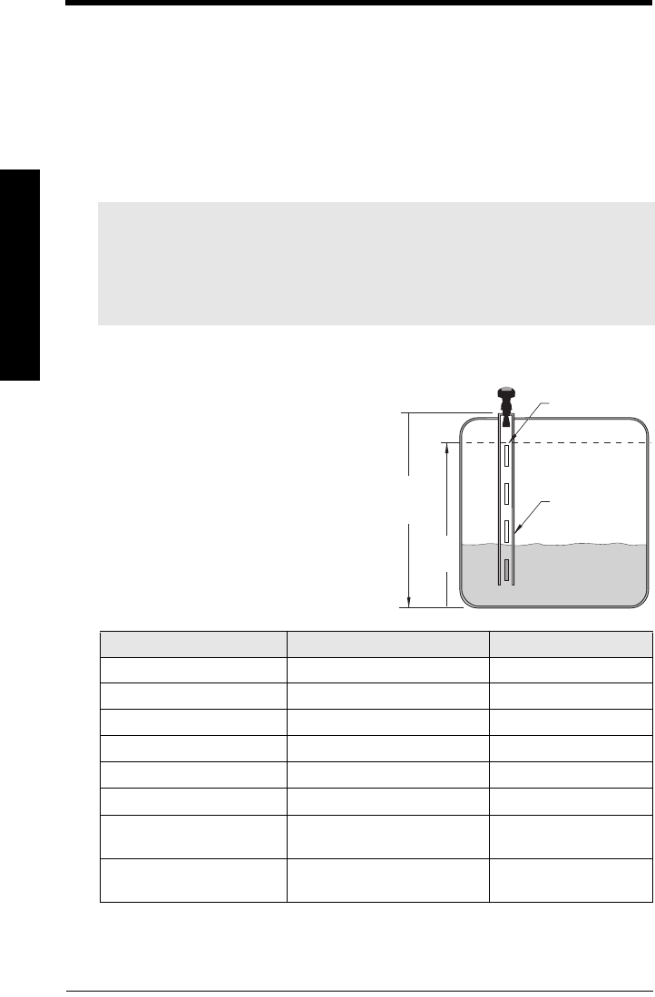
Page 116 SITRANS LR250 (HART) – INSTRUCTION MANUAL 7ML19985JE01
mmmmm
G: Special Applications
Appendix G: Special Applications
This more complex SITRANS LR250 application example can be used for setup
references.
Application Example: Stillpipe
This is used for products with an εr of less than 3, or if extremely turbulent or vortex
conditions exist. This mounting arrangement can also be used to provide optimum signal
conditions on foaming materials.
This application is to obtain a level measurement and corresponding 4 to 20 mA output
proportional to the oil level in a fuel storage vessel.
Notes:
•For εr < 3, the lower 400 mm of vessel level may not be measurable.
•
2.2.1.12. Near Range
(Blanking) will be set at the factory. Check the process device
tag for specific values.
• Suitable pipe diameters are 50 mm (2”) to 100 mm (4”): See the chart on page 108 for
typical
2.2.1.14. Propagation Factor
values.
Parameter Enter
2.2.1.5. Operation
1= level
2.2.7.1. Response Rate
2= 1 m/minute
2.2.1.4. Sensor Units
1= meters
2.2.1.6. Low Calibration Pt.
5= 5 m
2.2.1.7. High Calibration Pt.
4.5 = 4.5 m
2.2.1.14. Propagation Factor
1
1. See under
2.2.1.14. Propagation Factor
on page 66 for atable showing suggested val-
ues.
0.998 = 100 mm pipe I.D.
2.2.5.7. Range (Auto Sup-
pression Range)
distance to material – 0.42 m
2.2.5.6. Auto False Echo
Suppression
2 enable false-echo
suppression
• The reference point of SITRANS LR250 is
5 m (16.5 ft) from the vessel bottom.
• Low Calibration Pt. is 0 m/ft (bottom of
tank).
• High Calibration Pt. is 4.5 m (14.74 ft) from
the bottom.
• The stillpipe inside diameter is 100 mm (4").
• The maximum rate of filling or emptying is
about 0.1 m (4")/min.
vent slots
5 m
P006
4.5 m
P007

7ML19985JE01 SITRANS LR250 (HART) – INSTRUCTION MANUAL Page 117
mmmmm
H: HART Communications
Appendix H: HART Communications
Highway Addressable Remote Transducer, HART, is an industrial protocol that is
superimposed on the 4-20 mA signal. It is an open standard, and full details about HART
can be obtained from the HART Communication Foundation at www.hartcomm.org
SITRANS LR250 Rev 3 can be configured over the HART network using either the HART
Communicator 3751 by Fisher-Rosemount, or a software package. The recommended
software package is the SIMATIC Process Device Manager (PDM) by Siemens.
SIMATIC PDM
This software package is designed to permit easy configuration, monitoring, and
troubleshooting of HART devices. The HART DD for SITRANS LR250 was written with
SIMATIC PDM in mind and has been extensively tested with this software.
For more information, see
Operating SITRANS LR250 via SIMATIC PDM
on page 52.
HART Device Description (DD)
In order to configure a HART device, the configurator must have the HART Device
Description for the instrument in question. HART DDs are controlled by the HART
Communication Foundation. Please check with the HART Communication Foundation for
the availability of the HART DD for SITRANS LR250. Older versions of the library will have
to be updated in order to use all the features of SITRANS LR250.
1. Versions of SITRANS LR250 earlier than Rev. 3 can be configured using the HART
Communicator 275.
Page 118 SITRANS LR250 (HART) – INSTRUCTION MANUAL 7ML19985JE01
mmmmm
H: HART Communications
HART Communicator 375
Chart 1
Notes:
• HART Communicator 375 is supported by SITRANS LR250 HART Rev. 3.03. The menu
structure is aligned with the menu structure of SIMATIC PDM.
1. PV
2. Level
3. % Range
4. AO
5. Device Setup
6. Refresh
1. Master Reset
2. Quick Setup
3. Display
4. Diagnostics
5. PV Exchange
6. Device Data
7. Rate
8. Review
1. Material
2. Space
3. Distance
4. Volume
5. Error Signal
1. Wear
2. Status
3. Self Test
4. Range Calibration
5. Trim Analog Output
6. Simulate AO
1. Read AnalogOut
2. Select AnalogOut
1. Run Time
2. Number
3. Max Temp
4. Int Temp
On Line Device Setup
Display
Wear
Diagnostics
PV Exchange
Device Data
Range Calibration
1. Units
2. Empty
3. Span
4. Language
5. Operation
6. Response
7. Sensor
Quick Setup
1. Max Fill
2. Max Empty
Rate
1. Lock
2. Operation
3. Response
4. Sensor
5. Units
6. Empty
Review
1. Sensor Status
1. Electronics Status
2. Software Status
3. Application Status
Status
1. Self Test
Self Test
1. Offset
2. Prop Factor
1. D/A Trim
2. Scaled D/A
Trim Analog Output
1. Units
2. Basic Setup
3. Detailed Setup
4. Output Param
5. Device Information
6. HART Information
Basic Setup (See Chart 2)
Detailed Setup (See Chart 3)
Output Parameter (See Chart 4)
Device information
1. Tag
2. Descriptor
3. Message
4. Final Asmbly Num
5. Last Config
6. Manufacturer Data
HART information
1. Manufacturer
2. Model
3. HART Dev. I.D.
4. Universal Rev.
5. Fld. Dev. Rev.
6. Software Rev.
7. Hardware Rev.

7ML19985JE01 SITRANS LR250 (HART) – INSTRUCTION MANUAL Page 119
mmmmm
H: HART Communications
Chart 2
1. Master Reset
2. Standard Setup
3. Quick Setup
4. Volume
5. Failsafe
1. URV
2. LRV
3. Damping
1. Units
2. Empty
3. Span
4. Language
5. Operation
6. Response
7. Antenna
1. Shape
2. Max Vol
3. Dimension A
4. Dimension L
5. Bk LevVol Gr
1. mA Function
2. FS Timer
3. FS Default Measurement
4. FS Advance
5. FS Level val
Basic Setup Standard Setup
Quick Setup
Volume
Failsafe
1. Bk Lev1Val
2. Bk Vol1Val
3. Bk Lev2Val
4. Bk Vol2Val
5. Bk Lev3Val
6. Bk Vol3Val
7. Bk Lev4Val
8. Bk Vol4Val
9. Bk Lev5Val
10. Bk Vol5Val
11. Bk Lev6Val
12. Bk Vol6Val
13. Bk Lev7Val
14. Bk Vol7Val
15. Bk Lev8Val
16. Bk Vol8Val
17. Bk Lev9Val
18. Bk Vol9Val
19. Bk Lev10Val
20. Bk Vol10Val
21. Bk Lev11Val
22. Bk Vol11Val
23. Bk Lev12Val
24. Bk Vol12Val
25. Bk Lev13Val
26. Bk Vol13Val
27. Bk Lev14Val
28. Bk Vol14Val
29. Bk Lev15Val
30. Bk Vol15Val
31. Bk Lev16Val
32. Bk Vol16Val
33. Bk Lev17Val
34. Bk Vol17Val
35. Bk Lev18Val
36. Bk Vol18Val
37. Bk Lev19Val
38. Bk Vol19Val
39. Bk Lev20Val
40. Bk Vol20Val
41. Bk Lev21Val
42. Bk Vol21Val
43. Bk Lev22Val
44. Bk Vol22Val
45. Bk Lev23Val
46. Bk Vol23Val
47. Bk Lev24Val
48. Bk Vol24Val
49. Bk Lev25Val
50. Bk Vol25Val
51. Bk Lev26Val
52. Bk Vol26Val
53. Bk Lev27Val
54. Bk Vol27Val
55. Bk Lev28Val
56. Bk Vol28Val
57. Bk Lev29Val
58. Bk Vol29Val
59. Bk Lev30Val
60. Bk Vol30Val
61. Bk Lev31Val
62. Bk Vol31Val
63. Bk Lev32Val
64. Bk Vol32Val
Page 120 SITRANS LR250 (HART) – INSTRUCTION MANUAL 7ML19985JE01
mmmmm
H: HART Communications
Chart 3
Chart 4
Detailed Setup
1. Echo Lock
2. Echo Select
3. TVT Setup
4. Echo Quality
1. Algorithm
2. Blanking
3. Rng Ext
Echo Select
TVT Setup
Echo Quality
Echo Lock
1. Auto TVT
2. Range
3. Hover
1. Confidence
2. Strength
3. Noise Average
4. Noise Peak
5. Threshold Long
1. Echo Lock
2. Sampling Up
3. Sampling Down
4. Window
1. Poll Addr
2. Num Req Preams
3. Num Resp Preams
Analog Ouput
1. Write Protect
2. Lock
3. Write Protect
4. Unlock Value
Output parameter
1. Analog Output
2. Apply Values
3. Local Display.
4. HART Output
Local Display
HART Output
1. Read AnalogOut
2. mA Function
3. FS Default Measurement
4. Min mA
5. Max mA
6. Low Setpoint
7. High Setpoint

7ML19985JE01 SITRANS LR250 (HART) – INSTRUCTION MANUAL Page 121
mmmmm
H: HART Communications
Supported HART Commands:
SITRANS LR 250 conforms to HART rev. 5 and supports the following:
Universal Commands
0, 1, 2, 3, 6, 7, 8, 11, 12, 13, 14, 15, 16, 17, 18, 19, 20, 21, 22
Common Practice Commands
33, 34, 35, 36, 37, 38, 40,41, 42, 44, 45, 46, 48, 50, 51, 53, 54, 59
Device Specific Commands
Command 150 Read Echo Summary
Command 151 Read Echo Data Profile
Command 162 Read Volume
Command 163 Write Volume
Command 164 Read Volume Breakpoint
Command 165 Write Volume Breakpoint
Command 166 Read Failsafe
Command 167 Write Failsafe
Command 170 Read Echo Lock
Command 171 Write Echo Lock
Command 172 Read TVT
Command 173 Write TVT
Command 174 Read TVT Shaper
Command 175 Write TVT Shaper
Command 178 Read Analog Special
Command 179 Write Analog Special
Command 182 Read Range Calibration
Command 183 Write Range Calibration
Command 186 Read Wear
Command 206 Read Confidence
Command 207 Write Confidence Threshold
Command 208 Read Local Display Commands
Command 209 Write Local Display Commands
Universal and Common Practice Commands
For details on the Universal and Common Practice Commands, please contact the HART
Communication Foundation.
Device Specific Commands
For a document containing the Device Specific Commands, please contact Siemens
Milltronics at techpubs.smpi@siemens.com.

Page 122 SITRANS LR250 (HART) – INSTRUCTION MANUAL 7ML19985JE01
mmmmm
J: Sorftware Revision
Appendix L: Software Revision History
Soft-
ware
Rev.
DD
Rev. Date Changes
• Initial release

7ML19985JE01 SITRANS LR250 (HART) – INSTRUCTION MANUAL Page 123
mmmmm
Glossary
Glossary
accuracy: degree of conformity of a measure to a standard or a true value.
agitator: mechanical apparatus for mixing or aerating. A device for creating turbulence.
algorithm: a prescribed set of well-defined rules or processes for the solution of a problem in a
finite number of steps.
ambient temperature: the temperature of the surrounding air that comes in contact with the
enclosure of the device.
antenna: an aerial which sends out and receives a signal in a specific direction. There are four
basic types of antenna in radar level measurement, horn, parabolic, rod, and waveguide.
attenuation: a term used to denote a decrease in signal magnitude in transmission from one
point to another. Attenuation may be expressed as a scalar ratio of the input magnitude to
the output magnitude or in decibels.
Auto False-Echo Suppression: a technique used to adjust the level of a TVT curve to avoid the
reading of false echoes. (See TVT.)
Auto False-Echo Suppression Distance: defines the endpoint of the TVT distance. (See TVT.)
This is used in conjunction with auto false echo suppression.
beam width: the angle diametrically subtended by the one-half power limits (-3 dB) of the
microwave beam.
beam spreading: the divergence of a beam as it travels through a medium.
blanking: a blind zone extending away from the reference point plus any additional shield
length.The instrument is programmed to ignore this zone.
capacitance: the property of a system of conductors and dielectrics that permits the storage of
electricity when potential differences exist between the conductors. Its value is
expressed as the ratio of a quantity of electricity to a potential difference, and the unit is a
Farad.
confidence: describes the quality of an echo. HIgher values represent higher quality.
Confidence threshold defines the minimum value.
damping: term applied to the performance of an instrument to denote the manner in which the
measurement settles to its steady indication after a change in the value of the level.
dB (decibel): a unit used to measure the amplitude of signals.

Page 124 SITRANS LR250 (HART) – INSTRUCTION MANUAL 7ML19985JE01
mmmmm
Glossary
derating: to decrease a rating suitable for normal conditions according to guidelines specified
for different conditions.
dielectric: a nonconductor of direct electric current.1
dielectric constant (DK): the ability of a dielectric to store electrical potential energy under the
influence of an electric field. Also known as Relative Permittivity. An increase in the
dielectric constant is directly proportional to an increase in signal amplitude. The value is
usually given relative to a vacuum /dry air: the dielectric constant of air is 11.
echo: a signal that has been reflected with sufficient magnitude and delay to be perceived in
some manner as a signal distinct from that directly transmitted. Echoes are frequently
measured in decibels relative to the directly transmitted signal.
echo confidence: the recognition of the validity of the echo. A measure of echo reliability.
Echo Lock Window: a window centered on an echo in order to locate and display the echo’s
position and true reading. Echoes outside the window are not immediately processed.
Echo Marker: a marker that points to the processed echo.
Echo Processing: the process by which the radar unit determines echoes.
Echo Strength: describes the strength of the selected echo in dB above 1 µV rms.
Echo Profile: a graphical display of a processed echo.
false echo: any echo which is not the echo from the desired target. Generally, false echoes are
created by vessel obstructions.
frequency: the number of periods occurring per unit time. Frequency may be stated in cycles
per second.
hertz (Hz): unit of frequency, one cycle per second. 1 Gigahertz (GHz) is equal to 109 Hz.
HART: Highway Addressable Remote Transducer. An open communication protocol used to
address field instruments.
horn antenna: a conical, horn-shaped antenna which focuses microwave signals. The larger
the horn diameter, the more focused the radar beam.
inductance: the property of an electric circuit by virtue of which a varying current induces an
electromotive force in that circuit or in a neighboring circuit. The unit is a Henry.
microwaves: the term for the electromagnetic frequencies occupying the portion of the radio
frequency spectrum from 1 GHz to 300 GHz.
1. Many conductive liquids/electrolytes exhibit dielectric properties; the relative dielec-
tric constant of water is 80.

7ML19985JE01 SITRANS LR250 (HART) – INSTRUCTION MANUAL Page 125
mmmmm
Glossary
multiple echoes: secondary echoes that appear as double, triple, or quadruple echoes in the
distance from the target echo.
Near Blanking: see Blanking
nozzle: a length of pipe mounted onto a vessel that supports the flange.
parameters: in programming, variables that are given constant values for specific purposes or
processes.
polarization: the property of a radiated electromagnetic wave describing the time-varying
direction and amplitude of the electric field vector.
polarization error: the error arising from the transmission or reception of an electromagnetic
wave having a polarization other than that intended for the system.
propagation factor (pf): where the maximum velocity is 1.0, pf is a value that represents a
reduction in propagation velocity as a result of the wave travelling through a pipe or
medium.
pulse radar: a radar type that directly measures distance using short microwave pulses.
Distance is determined by the return transit time.
radar: radar is an acronym for RAdio Detection And Ranging. A device that radiates
electromagnetic waves and utilizes the reflection of such waves from distant objects to
determine their existence or position.
range: distance between a transmitter and a target.
range extension: the distance below the zero percent or empty point in a vessel.
relative humidity: the ratio of the actual amount of moisture in the atmosphere to the maximum
amount of moisture the atmosphere could hold (which varies depending on the air
temperature).
relative permittivity: see dielectric constant.
repeatability: the closeness of agreement among repeated measurements of the same
variable under the same conditions.
shot: one transmit pulse or measurement.
speed of light: the speed of electromagnetic waves (including microwave and light) in free
space. Light speed is a constant 299, 792, 458 meters per second.
stillpipe: a pipe that is mounted inside a vessel parallel to the vessel wall, and is open to the
vessel at the bottom.

Page 126 SITRANS LR250 (HART) – INSTRUCTION MANUAL 7ML19985JE01
mmmmm
Glossary
stilling-well: see stillpipe.
two wire radar: a low-energy radar. Can be loop powered, analog, intrinsically safe 4 to 20 mA,
or a digital (BUS) transmitter.
TVT (time varying threshold): a time-varying curve that determines the threshold level above
which echoes are determined to be valid.
waveguide antenna: a hollow, metallic tube that transmits a microwave signal to the product
target.

7ML19985JE01 SITRANS LR250 (HART) – INSTRUCTION MANUAL Page 127
mmmmm
Index
Index
A
Abbreviations and Identifications
list 2
activating LR 460 33
address 90
agitator blade detection
avoiding 72
agitators 72
analog output
in Measure mode 110
response rate 106
application example 37
application examples
horizontal tank with volume 59
liquid resin in storage vessel 58
Auto False-Echo Suppression 108
TVT shaper adjustment 56
B
beam spreading 13
blanking (see Near Range) 108
C
cables
requirements 24
cleaning
instructions 104
conduits
requirements 24
D
device description
HART 117
Device Description (DD)
how to update 54
E
echo confidence 107
Echo Lock
explanation 107
emission cone
requirements 13
enclosure
opening 24
rotating 15
F
factory reset
via PDM 55
failsafe timer 111
Fail-safe Timers 107
false echo suppression 108
false echoes
set TVT curve to ignore 108
flange sizes
chart 23
function keys
navigation mode 49
H
HART
device description 117
HART Communications
details 117
hazardous area installations
wiring requirements 25
I
Identifications and Abbreviations
list 2
installation
hazardous area requirements 25
requirements 11
internal temperature
monitoring 111
L
Level application example 37
level trend viewing
yT diagram in PDM 56
lid-lock set screw 24
locking ring 15, 24
loop voltage vs. loop resistance
power supply requirements 26
loss of echo
definition 107
M
mA output in Measure mode 110
maintenance
cleaning 104
maintenance settings 81
material mixers 72
Measurement Response
explanation 106
mounting (standard)
horn antennas 14
shielded rod 14
N
Near Range (blanking) 108

7ML19985JE01 SITRANS LR250 (HART) – INSTRUCTION MANUAL Page 128
mmmmm
Index
O
operating principles 105
P
parameter reset
factory reset via PDM 55
parameter settings
adjust via PDM 52
PDM
see SIMATIC PDM 52
pipe sizes 23
power source
requirements 24
power supply requirements
loop voltage vs. loop resistance 26
process temperature
maximum 111
PROFIBUS address 90
programming chart 95
Programming SITRANS LR 460 34
Q
Quick Start (PDM)
helpful hints 40
launching 39
Quick Start Wizard
via handheld programmer 35
via SIMATIC PDM 38
R
receiver signal 106
reset parameters
via PDM 55
S
settings
adjust parameters via PDM 52
SIMATIC PDM
overview 52
Quick Start 39
Rev. 6.0, SP2 features 52
SITRANS LR 200
overview 4
SITRANS LR250
operating principles 105
stillpipe
weld requirements 16
Support
contact information 2
T
temperature de-Rating
charts 112
temperature specification
Ambient/Operating 12
terminals
accessing 24
troubleshooting
communications 97
operation 101
TVT curve 108
TVT Shaper
manual adjustment via PDM 56
V
vessel shape
conical top 12
parabolic top 12
selection 67
W
welded joints
requirements 16
wiring
cables 24
Y
yT Diagram
level trend viewing 56

7ML19985JE01 SITRANS LR250 (HART) – INSTRUCTION MANUAL Page 129
mmmmm
Index

Page 130 SITRANS LR250 – INSTRUCTION MANUAL 7ML19985JE01
mmmmm
LCD menus
LCD menu structure
1. QUICK START
1.1 APPLICATION
1.2 RESPONSE RATE
1.3 SENSOR UNITS
1.4 OPERATION
1.5 LOW CALIB. PT.
1.6 HIGH CALIB. PT.
1.7 APPLY?
2. SETUP
2.1 DEVICE
2.1.1 LCD CONTRAST
2.2 INPUT
2.2.1 SENSOR CALIB.
2.2.1.1 ANTENNA
2.2.1.2 APPLICATION
2.2.1.3 RESPONSE RATE
2.2.1.4 SENSOR UNITS
2.2.1.5 OPERATION
2.2.1.6 LOW CALIB. PT.
2.2.1.7 HIGH CALIB. PT.
2.2.1.11 NEAR RANGE
2.2.1.12 FAR RANGE
2.2.1.13 PROPAG. FACTOR
2.2.1.14 LEVEL OFFSET
2.2.2 VOL CONVERSION
2.2.2.1 VESSEL SHAPE
2.2.3 VOLUME BREAKPT
2.2.3.1 MAX. VOLUME
2.2.3.2 DIMENSION A
2.2.3.3 DIMENSION L
2.2.3.4 TABLE 1 – 8
2.2.3.5 TABLE 9 – 16
2.2.3.6 TABLE 17 – 24
2.2.3.7 TABLE 25 – 32
2.2.4 ECHO PROC.
2.2.4.1 ECHO SELECT
2.2.4.1.1 ALGORITHM
2.2.4.1.2 POSITION
2.2.4.1.3 ECHO THRESHOLD
2.2.4.2 SAMPLING
2.2.4.2.1 ECHO LOCK
2.2.4.2.4 SAMPLING UP
2.2.4.2.5 SAMPLING DOWN
2.2.4.2.6 WINDOW

7ML19985JE01 SITRANS LR250– INSTRUCTION MANUAL Page 131
mmmmm
LCD menus
2.2.4.3 FILTERING
2.2.4.3.2 DAMPING FILTER
2.2.4.4 TANK BOTTOM ALG
2.2.4.4.3 CLEF RANGE
2.2.4.5 NOISE
2.2.4.5.1 CONFIDENCE
2.2.4.5.2 STRENGTH
2.2.4.5.3 NOISE AVERAGE
2.2.5 TVT SETUP
2.2.5.1 TVT HOVER LEVEL
2.2.5.6 AUTO ECHO SUPP
2.2.5.7 AUTO SUPP RANGE
2.2.5.8 SHAPER MODE
2.2.6 TVT SHAPER
2.2.6.1 SHAPER 1-9
2.2.6.2 SHAPER 10-18
2.2.6.3 SHAPER 19-27
2.2.6.4 SHAPER 28-36
2.2.6.5 SHAPER 37-40
2.2.7 RATE
2.2.7.1 RESPONSE RATE
2.2.7.2 FILL RATE
2.2.7.3 EMPTY RATE
2.2.8 TB VALUES
2.2.8.1 READING MEAS.
2.2.8.2 MATERIAL MEAS.
2.2.8.3 SPACE MEAS.
2.2.8.4 DISTANCE MEAS.
2.2.8.5 VOLUME MEAS.
2.2.8.7 SENSOR VALUE
2.3 OUTPUT
2.3.1 MA OUTPUT
2.3.1.1 MA OUTPUT VALUE
2.3.1.2 MA OUTPUT FUNC.
2.3.1.3 4 MA SETPOINT
2.3.1.4 20 MA SETPOINT
2.3.1.5 MIN. MA LIMIT
2.3.1.6 MAX. MA LIMIT
2.3.1.7 4 MA OUTPUT TRIM
2.3.1.8 20 MA OUTPUT TRIM
2.4 FAIL-SAFE
2.4.1 FAILSAFE TIMERS
2.4.2 FAILSAFE MAT. LEVEL
2.4.4 FAILSAFE LEVEL
3. DIAGNOSTICS
3.1 ECHO PROFILE
3.14 MEAS. VALUES
3.14.1 CURR. INTERN. TEMP.
3.14.2 MAX. INTERN. TEMP.
3.14.3 MIN. INTERN TEMP.

Page 132 SITRANS LR250 – INSTRUCTION MANUAL 7ML19985JE01
mmmmm
LCD menus
3.15 REMAIN. DEV. LIFE
3.15.1 TOTAL OP--TIME
3.15.2 REMAIN. LIFETIME
3.15.3 MAINT REQ LIMIT
3.15.4 MAINT DEM LIMIT
3.15.5 ALERT ACTIVATION
3.15.6 TOTAL EXP. LIFE
3.15.7 MAINT STAT
3.15.8 ACK STATUS
3.15.9 ACK
3.16 REMAIN. SENS. LIFE
3.16.1 SENS OP--TIME
3.16.2 REMAIN. LIFETIME
3.16.3 MAINT REQ LIMIT
3.16.4 MAINT DEM LIMIT
3.16.5 ALERT ACTIVATION
3.16.6 TOTAL EXP. LIFE
3.16.7 MAINT STAT
3.16.8 ACK STATUS
3.16.9 ACK
4. SERVICE
4.1 FACTORY RESET
4.2 POWERED HOURS
4.4 POWERON RESETS
4.7 MANUF. DATE
4.8 SOFTWARE REV
4.9 LOADER REV
4.11 HARDWARE REV
4.12 MEM. TEST
4.17 SERVICE INTERVAL
4.17.1 TIME LAST SERV
4.17.2 MAINT REQ LIMIT
4.17.3 MAINT DEM LIMIT
4.17.4 ALERT ACTIVATION
4.17.5 SERVICE INTERVAL
4.17.6 MAINT STAT
4.17.7 ACK STATUS
4.17.8 ACK
4.18 CALIB. INTERVAL
4.18.1 TIME LAST CAL.
4.18.2 MAINT REQ LIMIT
4.18.3 MAINT DEM LIMIT
4.18.4 ALERT ACTIVATION
4.18.5 TOTAL CALIB.INTRV
4.18.6 MAINT STAT
4.18.7 ACK STATUS
4.18.8 ACK

7ML19985JE01 SITRANS LR250– INSTRUCTION MANUAL Page 133
mmmmm
LCD menus
5. COMMUNICATION
5.1 DEVICE ADDRESS
5.2 COMM. CONTROL
6. SECURITY
6.1 LOCK
6.2 UNLOCK VALUE
7. LANGUAGE