Sony Group IJ1001SNBT Energy Storage System User Manual 4
Sony Corporation Energy Storage System 4
Contents
- 1. User Manual 2
- 2. User Manual 1
- 3. User Manual 3
- 4. User Manual 4
User Manual 4
Energy Storage System “IJ1001SNBT”
57
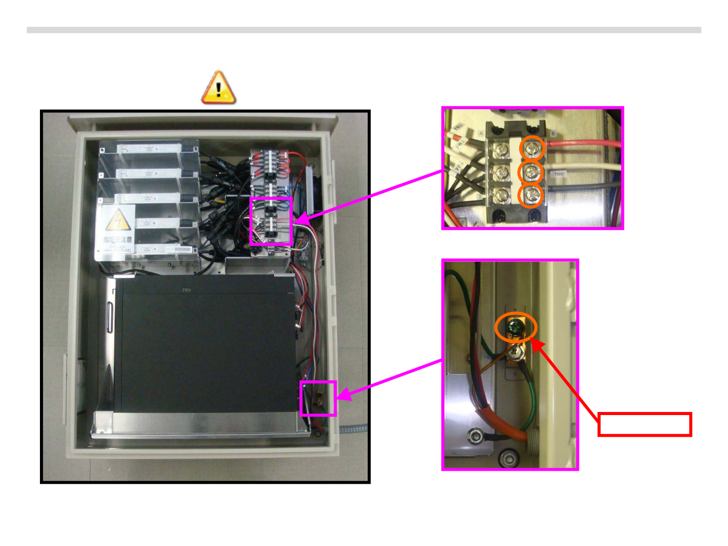
Set the connecting box and conduit
Wiring 4 position bellow.
Copyright Sony Energy Devices Corporation
Grounding
Energy Storage System “IJ1001SNBT”
58
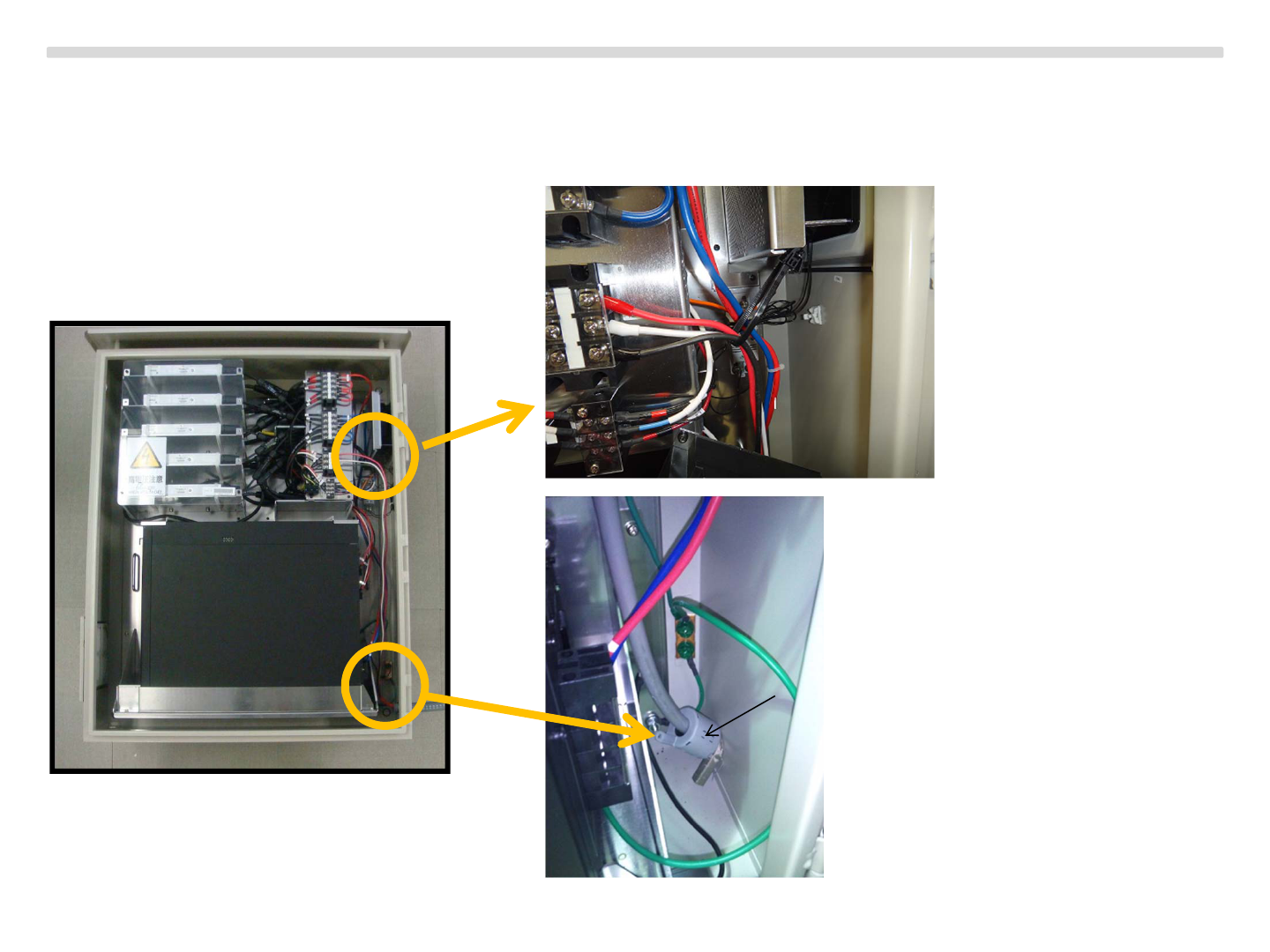
Set the connecting box and conduit
Tie the cables follow the bellow instruction and add some of magnetic core.
Copyright Sony Energy Devices Corporation
Tie the cables
Add the magnetic core provided by Sony
Energy Storage System “IJ1001SNBT”
59
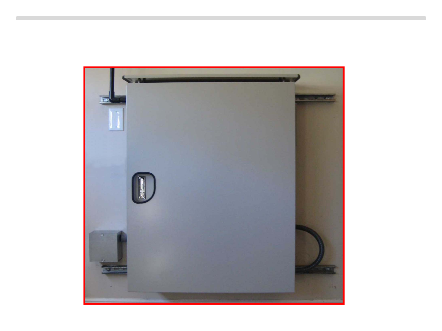
Set the connecting box and conduit
Set the front door then Completed.
Copyright Sony Energy Devices Corporation

Energy Storage System “IJ1001SNBT”
60
Copyright Sony Energy Devices Corporation
On site software update
Because of preinstalled software in factory, normally it is not required to install any software.
But in some cases, software update may be required on site.
On site software update procedure is as follows.
1.
2.
3. TBD
Energy Storage System “IJ1001SNBT”
61
Copyright Sony Energy Devices Corporation
Commissioning
CAUTION : Connect the energy storage system to the electrical utility grid only after
receiving prior approval from the utility company.
CAUTION : Be aware that only qualified personnel should must connect the energy
storage system to the electrical utility grid.
CAUTION : Ensure that all AC and DC wiring is correct. Ensure that none of the AC and
DC wires are pinched or damaged. Ensure that all junction boxes are properly closed
The Energy Storage System Activation
Connecting to the Internet
1. Confirm that there is a home router with wireless LAN working in the residence.
2. Connect with the home router using WPS.
Please follow a procedure below. (as same as normal WPS operation)
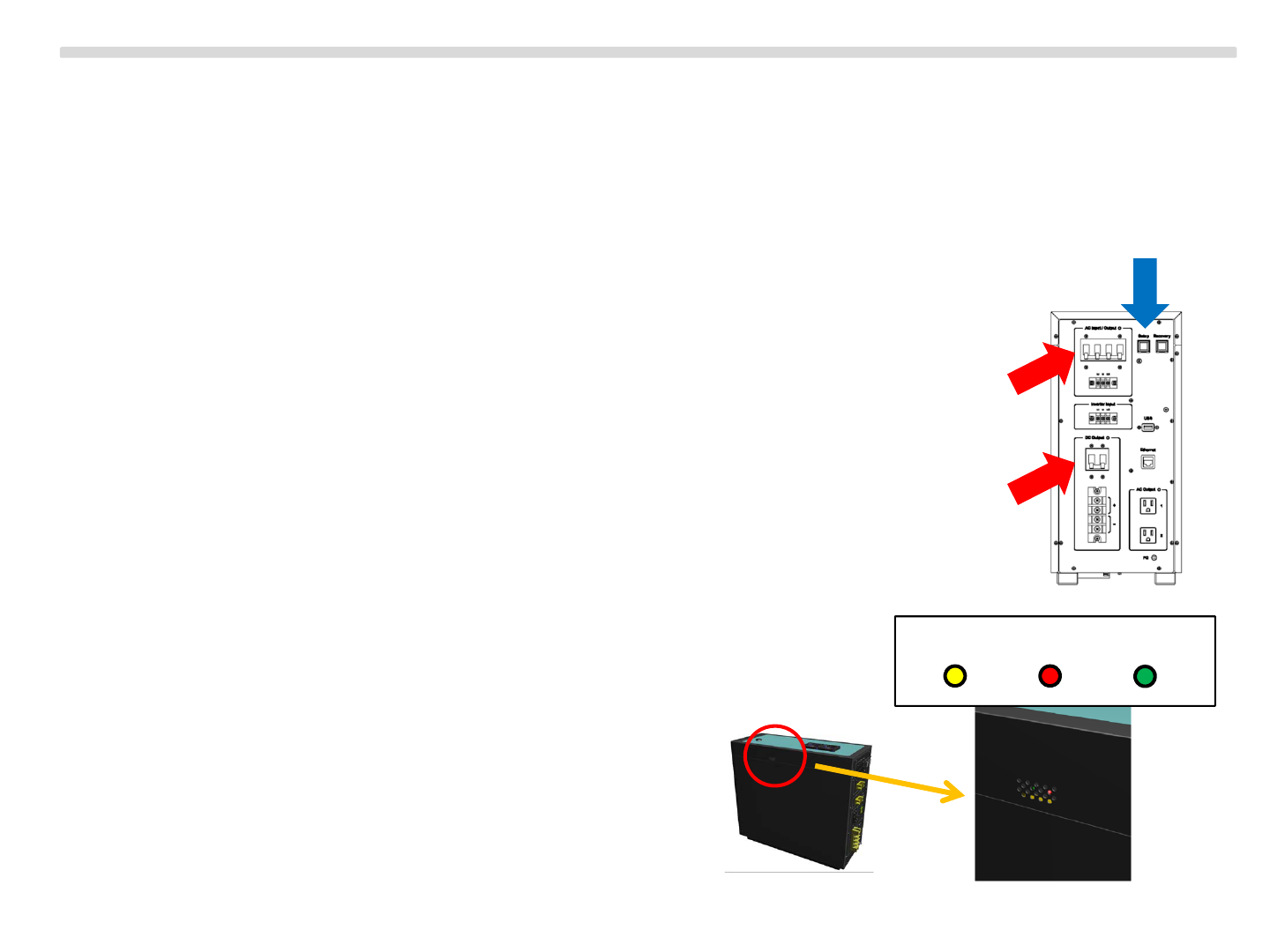
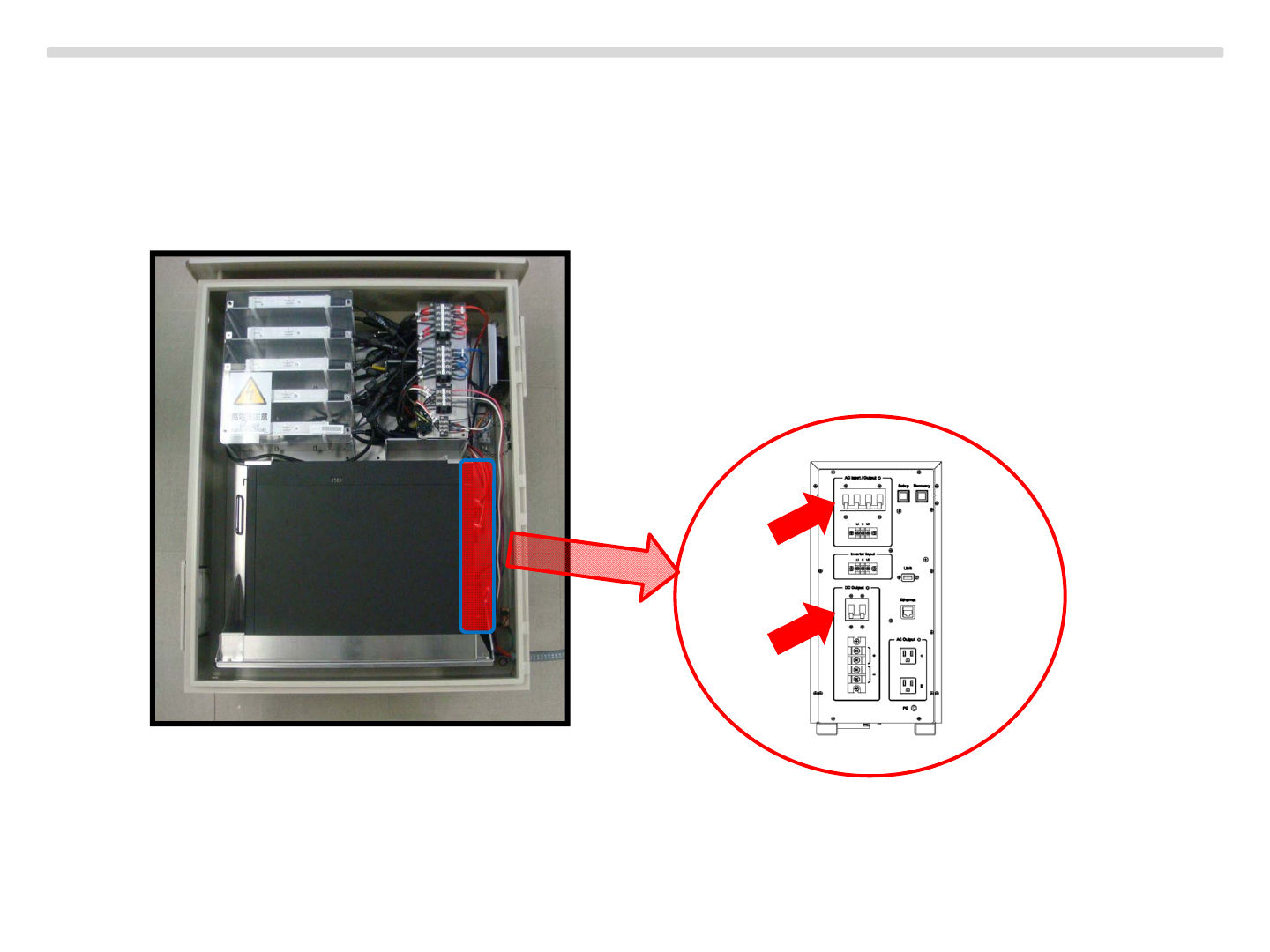
1. Turn ON the circuit protector located behind of the energy storage server.
( RED ARROWS )
2. Wait for booting the Energy Storage Server.
3. Push WPS button on the home router.
4. (Within 2 minutes) Push WPS button located
behind of the energy storage server.
( BLUE ARROW )
※While WPS period, WiFi LED is blinking.
After that, if WiFi LED stays turning ON,
WLAN setting is successfully completed.
If pattern of blinking is changed,
there is some error on WPS.
Please try again from step 1.
(turn OFF Energy Storage Server once)
62
WiFi Charge Discharge
The Energy Storage System Activation
Activating Energy Storage System for Field Trial
1. Turn ON the Energy Storage Server and wait for boot.
2. Confirm that the Energy Storage System is already connected to the Internet.
(WPS is already done)
3. Access to the cloud server to register the Energy Storage System, using Installer Web Application.
Installer Web Application is the same one for HEMS Gateway.
Please follow a procedure below. (as same as one for HEMS Gateway)
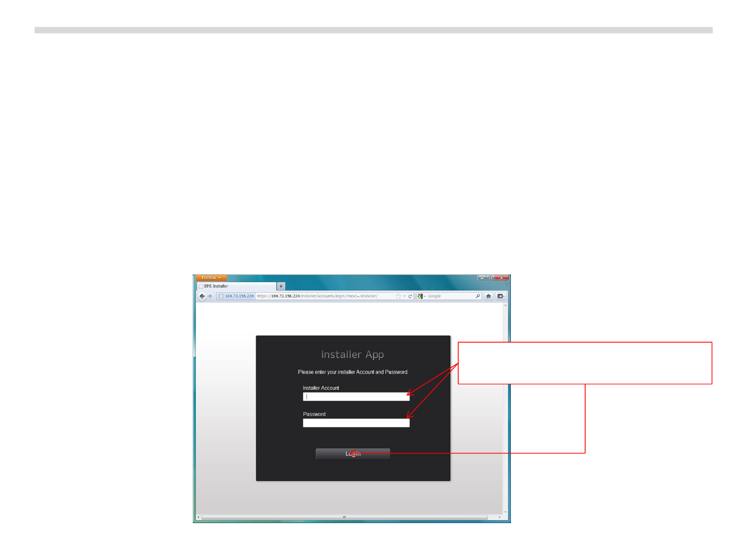
1. Login to the installer application. (need installer account and password)
63
Enter installer account and password.
Then push “Login” button.
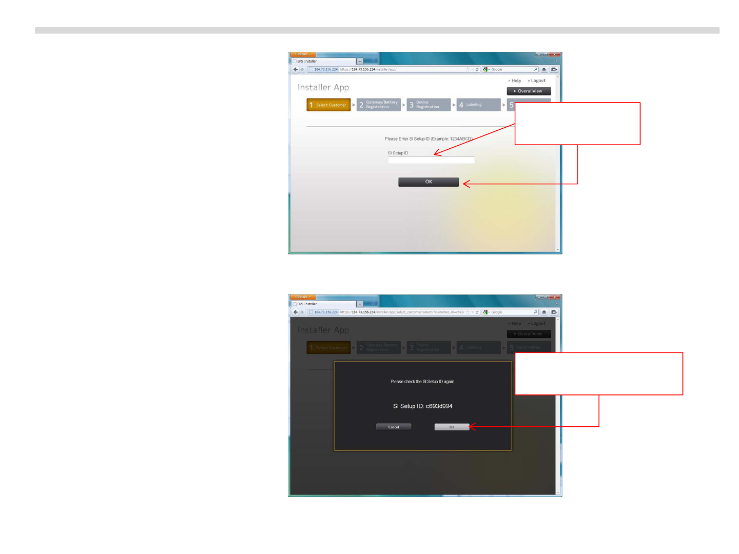
2. Input SI Setup ID.
3. Confirm SI Setup ID.
64
Input SI Setup ID
Then push OK
If SI Setup ID is correct,
then push OK
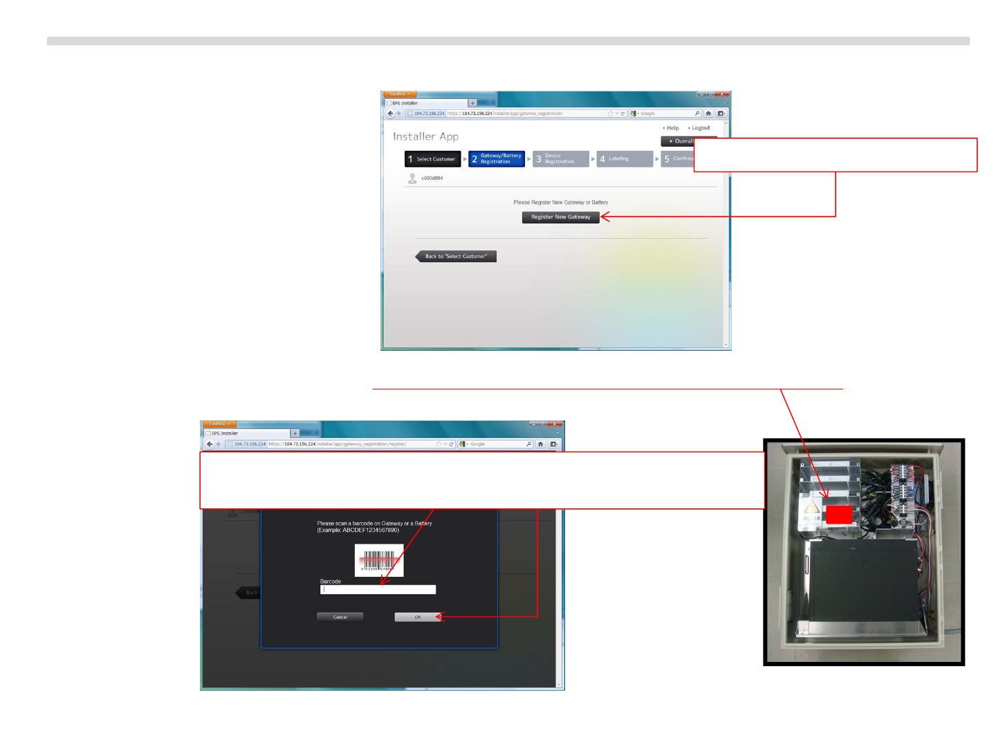
4. Go to registration process of Energy Storage System (called “Battery” in this application).
5. Scan barcode which is labeled on transparent acrylic board inside the outer enclosure.
65
Push “Register New Gateway”
If there is no barcode scanner, you can input barcode directly.
(080046xxxxxxxxxx) Then push “OK”
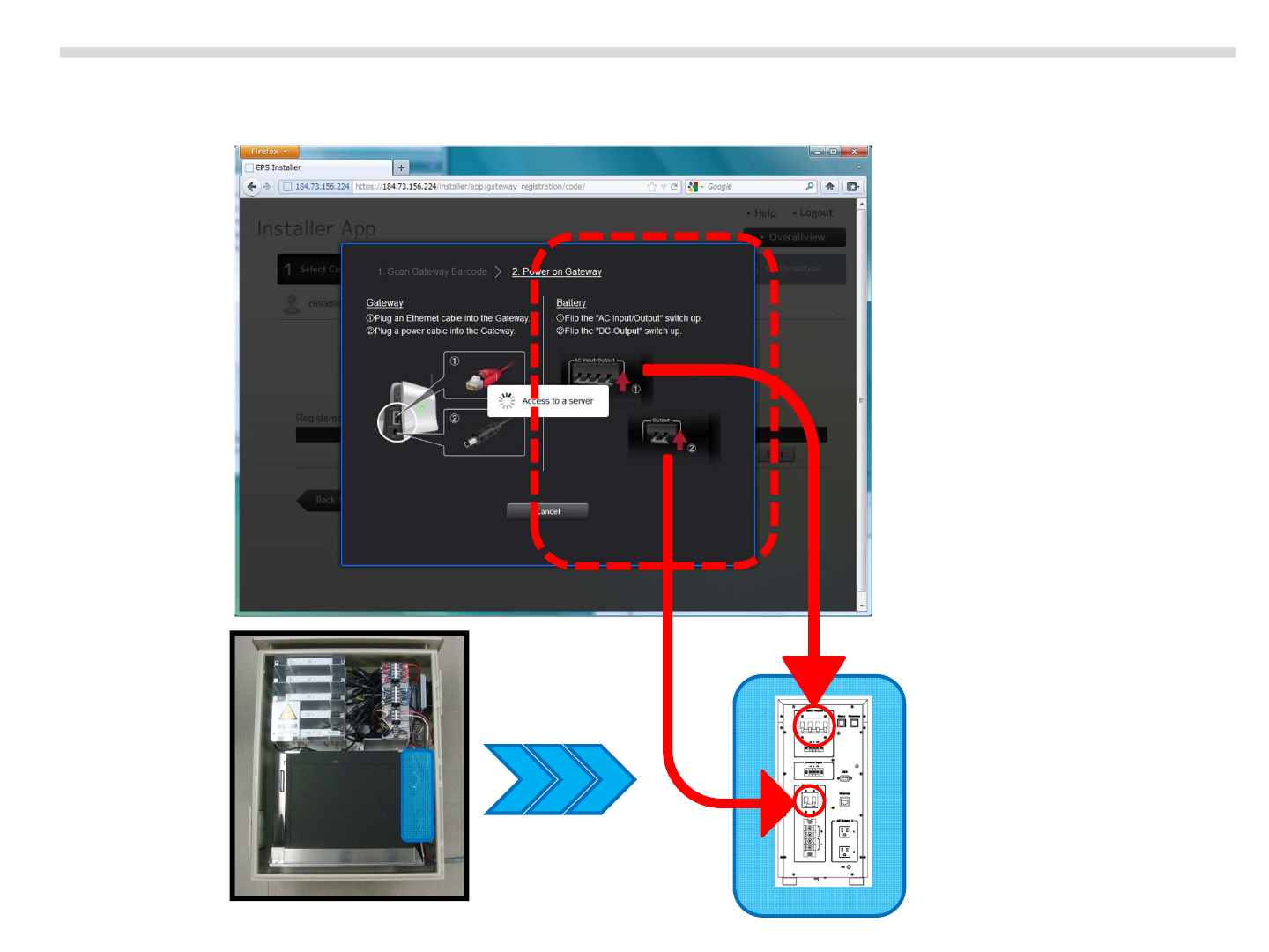
6. Confirm that Energy Storage System is powered on (called “Battery” in this application).
66
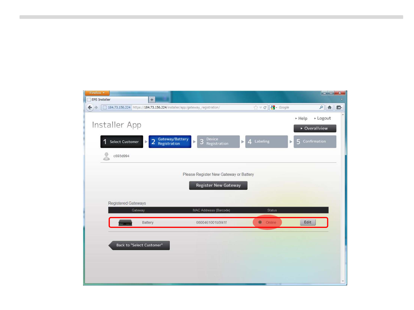
7. After waiting for a while※, it is successfully registered.
Confirm that Energy Storage System which is newly registered is listed in Registered Gateways
and its status is online.
※If Energy Storage System is already booted and ready, it is around 10-15 seconds.
But if you supply power in step6, it takes around 5 minutes.
67

APPENDIX
68
Energy Storage System “IJ1001SNBT”
69
Copyright Sony Energy Devices Corporation
How to Power ON/OFF the Energy Storage System
Power ON : Turn ON the circuit protector located behind of the energy storage server
inside the outer enclosure.
Power OFF : Turn OFF the breakers

Energy Storage System “IJ1001SNBT”
70
Copyright Sony Energy Devices Corporation
Indicator LEDs
Energy Storage Server
Inverter
There are five inverters in the outer enclosure.
Each inverter has a LED indicator at the center of side panel of one.
WiFi Charge Discharge
<Normal condition>
WiFi Charge Discharge
or
WiFi Charge Discharge
or
Startup LED Operation (beginning of discharge):
One minute after DC power is first applied to the inverter, six short green blinks indicate a successful
inverter startup sequence. Six short red blinks after DC power is first applied to the inverter indicate a
failure during inverter startup.
Post-Startup LED Indications:
Flashing Orange – Producing power
Flashing Red – Not producing power
GFDI Fault:
A solid red status LED when DC power has been cycled, indicates the inverter has detected a ground
fault (GFDI) error.