Thomson 2-8358AH 1.9DECT COLOR DISPLAY (128X128), HANDSFREE HANDSET PLUS CHARGER User Manual USERS MANUAL 1
Thomson Inc. 1.9DECT COLOR DISPLAY (128X128), HANDSFREE HANDSET PLUS CHARGER USERS MANUAL 1
Thomson >
Contents
- 1. USERS MANUAL 1
- 2. USERS MANUAL 2
- 3. USERS MANUAL 3
- 4. USERS MANUAL 4
- 5. USERS MANUAL 5
USERS MANUAL 1

1
Copyrights
© 2008 Thomson SA. All rights reserved. Republication or redistribution of Thomson content,
including by framing or similar means, is prohibited without the prior written consent of Thomson SA.
‘THOMSON’ and the Thomson logo are registered trademarks and trademarks of Thomson SA.
Other trademarks and technology protection
The following trademarks may be used in this document:
DECT is a trademark of ETSI.•
Ethernet™ is a trademark of Xerox Corporation.•
Wi-Fi® and the Wi-Fi Logo are registered trademarks of the Wi-Fi Alliance.•
Microsoft®, MS-DOS®, Windows® are either registered trademarks or trademarks of •
Microsoft Corporation in the United States and/or other countries.
Adobe®, the Adobe logo, Acrobat and Acrobat Reader are trademarks or registered •
trademarks of Adobe Systems, Incorporated, registered in the United States and/or other
countries.
DOCSIS and PacketCable are trademarks of Cable Television Laboratories, Inc.•
Macintosh and the Mac OS are trademarks of Apple Computer, Inc.•
All other company or product names are either trademarks or registered trademarks of their respective
owners.
This product contains free software code released under the GNU General Public License •
(GPL), Version 2 (available at http://www.gnu.org/licenses/gpl.txt). Anyone may obtain from
us a copy of the source code for the Linux packages. The full text of the GPL is included on
these materials. The source packages for these programs are available for download at http://
www.thomson.net/open-software. Those individuals without Internet access may request
that a CD-ROM or DVD containing the source code be sent to them by mail. To reimburse the
expenses incurred by creation, handling and postage, we will charge a €12 fee. To request
a CD ROM or DVD of the source code, send an e-mail to sylvie.cottret@thomson.net or mail
the request, with payment, to Sylvie Cottret, Thomson Telecom 46 Quai Alphonse Le Gallo
92100 Boulogne-Billancourt, France.
Disclaimer
Thomsonreservestherighttomodifythespecicationsandpicturesmentionedinthisdocumentatany
time and without prior notice. Therefore the information in these instructions is not contractual. For an
updated description, see http://www.thomson.net.
2
3
Safety
Safety Recommendations
Using Equipment Safely
Your Advanced Cable Gateway has been manufactured to meet American safety standards, but
care must be taken to ensure proper performance.
It is important that you read this booklet completely, especially the safety instructions below. If
you have any doubts about the installation, operation, or safety of the Gateway, please contact
your Customer Service.
Avoiding the Risk of Electric Shock
Disconnect the Gateway from the power source before you connect the Gateway to •
(or disconnect it from) any other equipment. Avoid any contact with the power source,
which can be lethal or cause severe electric shock.
Do not remove the cover of the Gateway. Should the Gateway fail, contact Customer •
Service for repair or service.
Do not insert anything into any opening of the case.•
Do not block the Gateway’s ventilation slots; do not place it on unstable surfaces like •
carpets.
Do not put anything on the Gateway which might spill or drip into it • (e.g. lighted
candles or liquids containers). Do not splash it with a liquid. If an object or liquid does
get inside the Gateway, unplug it immediately and contact Customer Service.
Do not store the Gateway in excessively hot, cold, or damp conditions. The Gateway is •
intended to operate at an ambient temperature of less than 113 degrees Fahrenheit (45
degrees Celsius) and a maximum humidity level of 75%.
In case of a thunderstorm, it is recommended that you unplug the Gateway from the •
power source and the antenna from the TV set.
Locate this equipment in such a way that the plug and power source are easily •
accessible. That way you can disconnect quickly.
Connecting to the Power Supply
This Gateway is designed to operate at 120VAC, 60Hz.•
If you are in any doubt about the • power source, the plug, or connection, please consult
Customer Service.
Ensuring optimum performance
Leave 3 to 4 inches of clearance around the Gateway to ensure proper ventilation to •
the Gateway.
Always place Gateway vertically.•
To clean the Gateway, use a dry, clean soft cloth with no cleaning solvent or abrasive •
products. Clean the ventilation openings regularly.
Environmental Information
The batteries contain some hazardous substances which pollute the environment. •
Do not dispose of them with other articles. Take care to dispose of them at special
collecting points.

4
Safety
Meaning of Symbols
This symbol is intended to alert the user to the presence of un-insulated
“dangerous voltage” within the product housing that may be of sufcient
magnitude to constitute a risk of shock.
This symbol is intended to alert the user to the presence of important operating
and maintenance (servicing) instructions accompanying the product.
FCC Radiation Exposure Statement
This equipment complies with FCC RF radiation exposure limits set forth for an uncontrolled
environment.
Base Station:
This device should be installed and operated with a minimum distance of 20 centimeters
between the radiator and your body. This transmitter and its antenna must not be co-located or
operating in conjunction with any other antenna or transmitter.
Portable Part (Phone):
For hand held operation, this phone has been tested and meets the FCC RF exposure guidelines.
North American Cable Installer
This reminder is provided to call your attention to Article 820-40 of the National Electrical
Code (Section 54 of the Canadian Electrical Code, Part 1) which provides guidelines for proper
grounding and, in particular, species that the cable ground shall be connected to the grounding
system of the building as close to the point of cable entry as practical.
Model Type ACG905 -- C
Operating Voltage 120V AC / 60 Hz / 0.5A
Typical Power Consumption 25W max
Weight 0.872 Ib / 0,395 kg
Dimensions (W x H x D) 7.79 x 7.68 x 3.94 Inch
Operating Temperature Range 59 to 95° F / 15 to 35°C
Storage Temperature Range - 4 to 158°F / - 20 to 70°C
Remote Control Battery Type Li-Ion 11.1V 2,150 mAh
Technical Specications
FCC Compliance Statement
This device complies with part 15 of the FCC rules. Operation is subject to the
following 2 conditions: 1. This device may not cause harmful interference; 2. This
device must accept any interference received, including interference that may
cause undesired operation. Responsible party (contact for FCC matter only):
THOMSON Inc.
101 W. 103rd St.
Indianapolis, IN 46290 U.S.A.
5
Contents
Table of Contents
Safety Recommendations 3
About your Advanced Cable Gateway 10
Key Features 10
Main Technical Characteristics 10
Computer Requirements 11
Before You Start 12
Box Contents 12
Gateway Overview 13
Front Panel 13
Rear Panel 14
Inserting Batteries 15
About Your Handset 16
Charging the Handset 17
Handset 19
Installing the Handset Batteries 19
Handset Technical Specication 20
Set-up 21
Connecting the Advanced Cable Gateway with other Devices 21
Connection Between Devices 22
1. How Does the Gateway Work? 22
2. What do you need to enjoy all services? 23
3. Establish an Internet Account 24
Connecting the Advanced Cable Gateway to a 25
Single Computer 25
1. Attaching the Cable TV Wire to the Advanced Cable Gateway 25
Ethernet Connection to One or Two Computers 26
Connecting More Than Two Computers to the Advanced Cable
Gateway 27
6
Contents
Telephone or Fax Connection 27
Legend 28
Activating the Advanced Cable Gateway 28
Lights Guide 28
Self Installation 31
Starting the Self Installation 31
Wi-Fi Connection 32
Light Indicators on the Front Panel 32
Wireless Internet Access for Your Computer 33
For a PC: 33
For a MAC: 33
Web Conguration 34
Accessing the Web Conguration 35
Overview 36
1. Handset Layout 36
2. Using the Keys 37
Day to Day Use 39
Making Calls 39
Receiving Calls 39
Ending Calls 39
Mute 40
Call Volume 40
Handset Screen Icons 41
Online Services 43
CreateUserProle 43
LoginUsingaUserProle 44
ProleSettings 45
Delete User 45
Auto Logout 46
Change Display Name 46
7
Contents
Call Log 47
Missed Calls 47
Missed Call Alert (pop up) 49
Answered Calls and Dialed Calls 50
Email 51
Access to your email 51
Options for Emails 52
Using the Address Book for Emails 54
Direct Entry Address 55
Address Book 56
Create Address Entry 56
Address Editing 58
Address Deleting 59
Copy to Phone Option 60
Calling Directly from Address Book 61
Voicemail 62
Acessing Your Voicemails 62
Playing Voicemail 63
Delete the Voicemail 64
Call the Voicemail Back 65
Save Number 65
Yellow Pages 66
All Directory Listings Search 67
Local Search Options 68
Saving Search Results 69
Dialing Search Results 69
Weather Updates 70
Headlines 71
News 71
Sports 71
Horoscope 72
Daily Diversions 72
8
Contents
Outline of Web Manager 73
Gateway – Status Web Page Group 74
1. Software 74
2. Connection 75
3. Password 75
Gateway – Telephony Web Page Group 76
1. Base 76
2. Handsets 76
Gateway – Router Web Page Group 77
1. LAN 77
2. WAN 78
3. Computers 78
4. Firewall 79
Minimum Level of Security 79
Medium Level of Security 79
5. Forwarding 80
Maximum Level of Security 80
6. DMZ Host 82
Gateway – Wireless Web Page Group 83
Performance 83
Authentication 83
Security 84
1. 802.11b/g Basic 84
2. 802.11b/g Security 86
3. Access Control 88
EMTA settings – Basic Web Page Group 89
1. Status 89
2. CM Hardware 90
3. Event Log 90
4. CM State 91
Customizing Your Handset 92
9
Contents
1. Charts of the Menus 92
2. Ring Tone 93
3. Time 94
4. Phone Settings 95
5. Call Lists 96
6. Using Your Phone With Multiple Handsets 97
Additional Information 99
Frequently Asked Questions 99
Troubleshooting 101
FCC Declaration of Conformity and Industry Canada
Information 103
Additional Headsets 104
Service Information 105
Glossary 106
Index 109
10
Introduction
About your Advanced Cable Gateway
Key Features
Thank you for choosing the ACG905, the new generation of Thomson
Gateways with enhanced functionalities. The Advanced Cable Gateway offers
the following services:
Multi-Line Capability, Up to 5 Handsets*•
Access to Voicemail, Address Book, News, Weather and other •
features via your Handset(s)
Built-in router functionality for home networking•
WiFi•
Main Technical Characteristics
DOCSIS 2.0 and PacketCable 1.5 Compliant•
Built-in DECT Technology•
Wireless (Add-On PC Card included)•
2 Ethernet Ports, 1 USB2.0 and 1 RJ11 Telephone Line•
Battery back-up•
Security Through Built-In Firewall and WEP, WPA, WPA2, BPI+ •
Protocols
Easy Access to Advanced Diagnostics Web Pages•
* Refer to page yada yada for information on ordering additional Handsets.

11
Introduction
IBM PC COMPATIBLE MACINTOSH
CPU Pentium preferred Power PC
Operating System Windows NT/2000/Me/XP/
Vista, Linux
Mac OS 10.4x
or higher
Video VGA or better (SVGA
preferred)
VGA or better (SVGA
built-in preferred)
Ethernet 10BaseT or 100BaseT 10BaseT or 100BaseT
An Ethernet card makes it possible for your computer
to pass data to and from the internet. You must have
an Ethernet card and software drivers installed in your
computer. You will also need a standard Ethernet cable
to connect the Ethernet card to your Advanced Cable
Gateway.
Software A TCP/IP network protocol for each machine
Microsoft Internet Explorer 6.0 or later or
Mozilla Firefox.
Computer Requirements
For the best possible performance from your Advanced Cable Gateway, your
personal computer must meet the following minimum system requirements:
Note:
The minimum requirements may vary among different cable companies.
12
Parts and Putting them Together
Before You Start
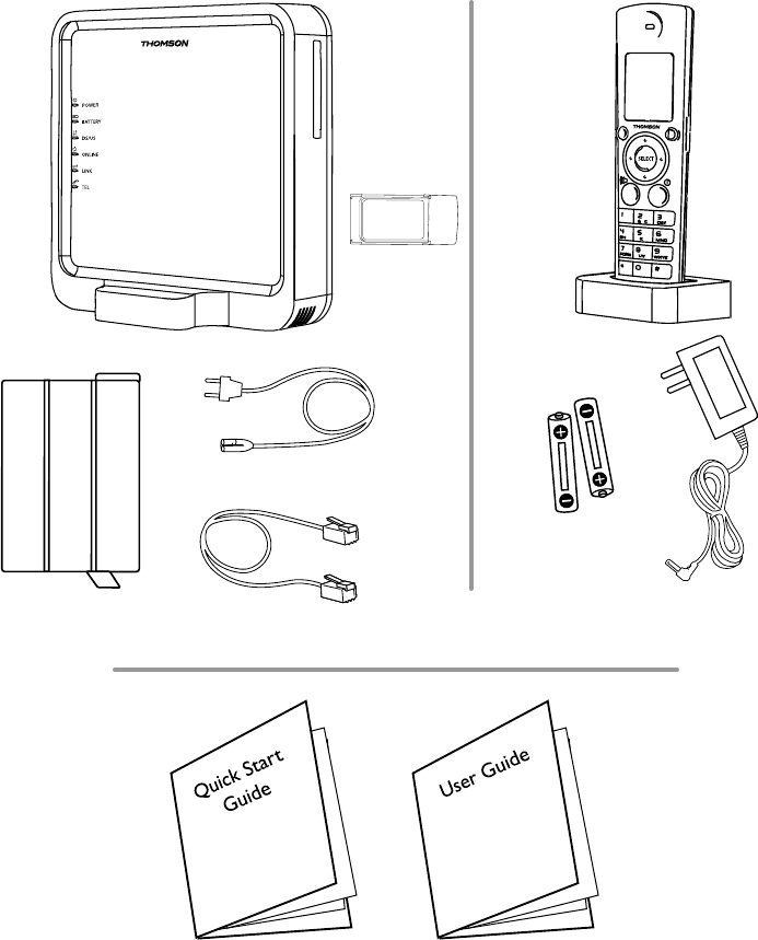
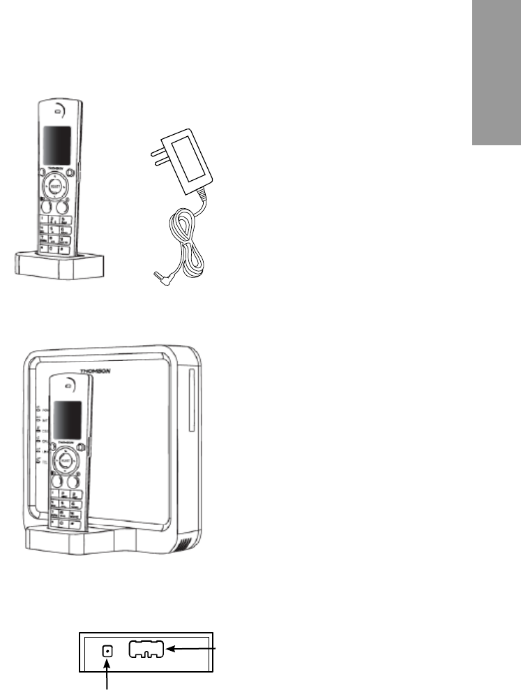
Box Contents
CAUTION
Advanced Cable Gateway
Battery
Rechargeable
Batteries
DC adapter for
DECT handset
Ethernet Cable
Power Cord
WiFi Card
DECT handset TH-58 with Dock
13
Parts and Putting them Together
Assemble
Gateway Overview
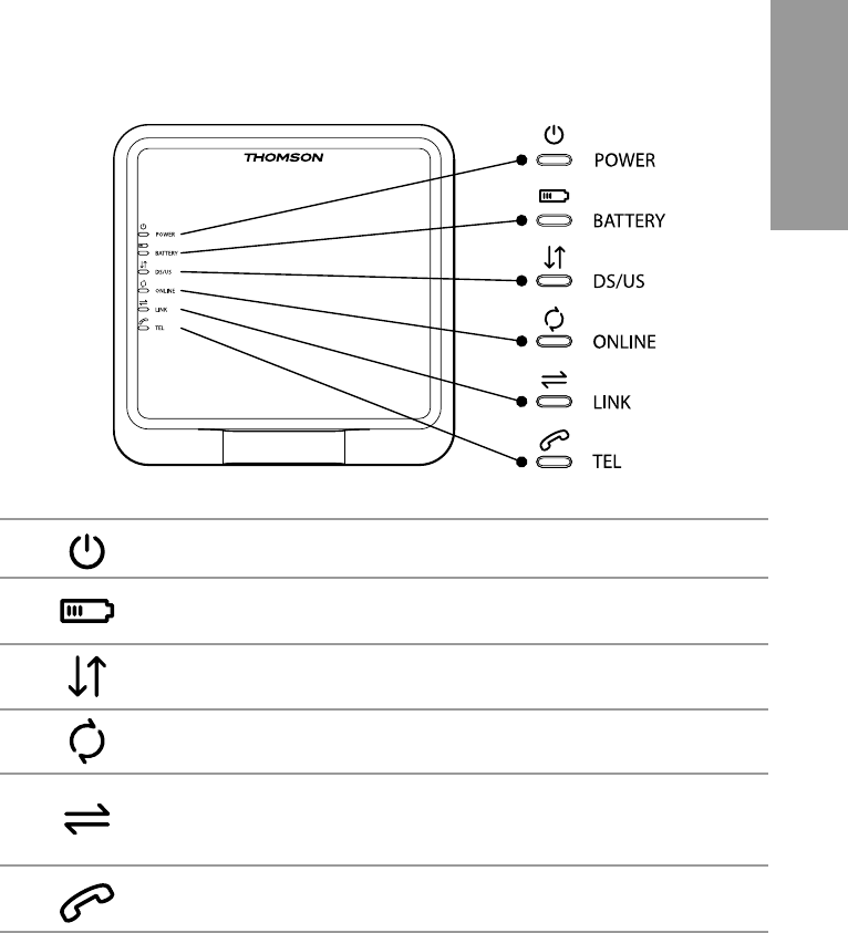
Front Panel
POWER Power
BATTERY Battery Back-Up Level
(low / full / empty or no battery detected)
DS/US Cable DOCSIS State;
LED ON during start-up operation
ONLINE Internet Active
LINK CPE Activity
LED ON when a PC is connected to the
Ethernet port
TEL Voice Over IP Information
14
Parts and Putting them Together
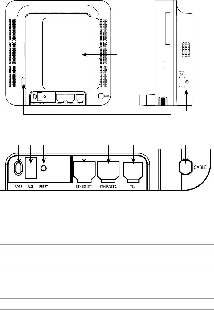
Rear Panel
Back-Up
Battery Cover
Power Input
Page USB RESET
120V AC. 60Hz, 0.5A
ETHERNET 1 ETHERNET 2 TEL CABLE
PAGE To ring all connected Handsets ( short press )
or
Add another DECT Handset to the Gateway ( press for more than
12 seconds )
or
Reset to factory settings ( press at power off; keep pressing for 5
seconds while powering on the ACG)
USB USB 2.0 Connector ( master )
RESET Reset ( short press )
ETHERNET 1 Ethernet 10/100 BaseT RJ-45 Connector
ETHERNET 2 Ethernet 10/100 BaseT RJ-45 Connector
TEL Telephone RJ-11 Connector
CABLE Cable Input; F-Connector
15
Parts and Putting them Together
Assemble
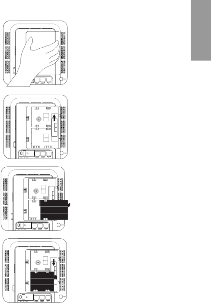
Inserting Batteries
To install batteries into the Advanced Cable Gateway:
Ensure the power cord is 1.
unplugged. Remove the battery
cover on the rear panel. There
are two battery compartments.
One battery is included with the
Advanced Cable Gateway.
For an additional battery please
contact your local operator.
Push the slider up/down to allow 2.
for battery insertion.
Insert the battery into the 3.
compartment marked
“Battery 1”.
Readjust the slider to prevent the 4.
battery from moving and replace
the battery cover. Plug the power
cord into an electrical outlet that
is not controlled by a wall switch
(this will assure that the unit has
uninterrupted power). The battery
will fully charge within 5 hours.

16
Parts and Putting them Together
As with any radio link, the quality of communication depends on the location
of the equipment and the environment in which it is used.
In particular your TH58 Handset must be protected from:
excessive heat (radiators, direct sunlight, etc.)
vibration
dust
Never allow your phone to come into contact with:
water
aerosols
To reduce the risk of interference and maximize reception, take particular
care not to locate the Handset or Dock close to:
halogen lamps (and other heat sources)
windows
large metal objects
reinforced concrete
televisions
music centers
uorescent lighting
burglar alarms
microwave ovens
computers, etc
About Your Handset
In order to understand the key features of your TH58 Handset, it is
recommended that you read this guide carefully, including all the safety
instructions, before using the product. It is recommended that you inform
other members of your family (especially your children) of the detailed
warnings given in this guide.
Caregivers of young children should monitor them at all times in the
presence of this product.
In particular, children should never be allowed to put unsuitable or
dangerous metal or plastic articles into their mouths.
When your TH58 Handset is connected to the Internet, you may download
software updates for the base and handset. Applying these updates and
the improvements they contain may slightly modify the menus shown in this
User’s Guide.
To clean your Handset, use an antistatic cloth.
17
Parts and Putting them Together
Assemble
CAUTION
The DECT Handset dock can be
plugged into the Advanced Cable
Gateway.
In this situation, the Advanced
Cable Gateway will be charging
your handset.
or
The DECT Handset dock can
be stationed away from the
Advanced Cable Gateway.
In this situation, be certain that
the DC adapter is attached to
both the dock and a power
outlet.
Charging the Handset
The DECT Handset will charge when securely placed in the Handset Dock
so long as the dock has power.
The dock can charge your handset in two ways.
DECT Handset
in its Dock
DC Adapter
DECT Handset Dock
attached to
ACG
DC adapter connector
goes here
Dock snaps
onto front of
ACG here
Back of Dock
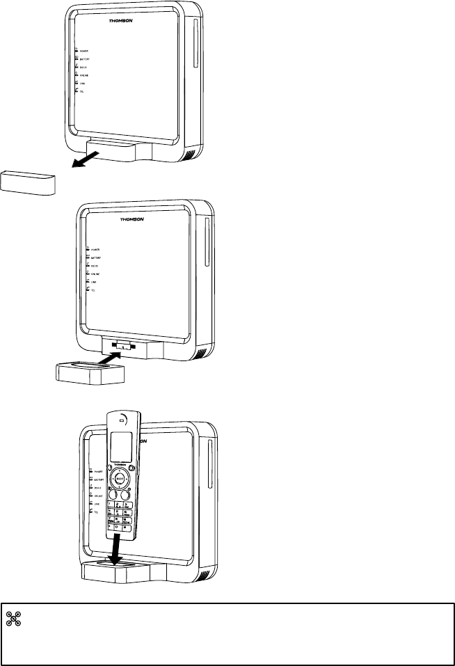
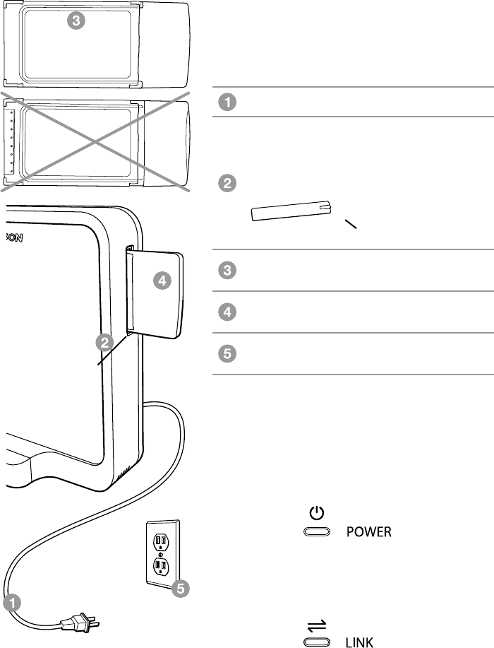
18
Parts and Putting them Together
Unplug the power cord to the 1.
Advanced Cable Gateway.
Remove the little ACG Cover 2.
on the front panel.
Attach the DECT Handset 3.
Dock where the cover was.
Place the Handset into its 4.
receptacle on top of the Dock.
Plug the power cord back into 5.
an outlet.
Handset Dock
ACG Cover
To plug your DECT Handset Dock on the Gateway, follow the instructions below:
Once installation is complete, you should leave the phone on the charger
for at least 5 hours before using it for calls and browsing content in order to
maximize battery performance and life.
19
Parts and Putting them Together
Assemble
Handset
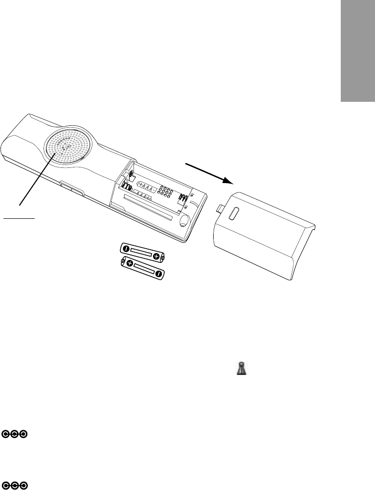
Installing the Handset Batteries
Slide the battery door off the back of the Handset.•
Insert the batteries • (included) into the housing in the Handset being
careful to align the + / - ends correctly (refer to the graphics in the
housing).
Check that the screen lights up, then replace the cover.•
Wait for about 1 minute to allow the system to start up.•
When your handset is registered to its base, •
the screen displays the number “1” alongside the (green - has
signal) symbol.
Note: Only use rechargeable batteries with exactlythesamespecications
as those supplied with the product.
Note: The use of a non-rechargeable or incompatible batteries may
damage the product and may be hazardous to health (please refer to
“TechnicalSpecications”onpage??).
CAUTION
Caution - special care should
always be taken with the
loudspeaker - never allow
anything to poke through or
pour into the holes. It is very
delicate.

20
Parts and Putting them Together
Free Field Range Up to 984 feet*
Indoor Range Up to 164 feet*
Number of Handsets 1 supplied
The base may be used with up to 5 handsets
Electrical Connection Powered from charger or direct to handset
(black power adapter unit):
Input: 100-240V AC 50/60 Hz
Output: 5V DC 200 mA
Rechargeable Battery 2 x 1.2V / 750 NIMH rechargeable batteries
Operating Temperature
Range
0 - 50°C
* Varies according to environment.
Handset Technical Specication
21
Parts and Putting them Together
Assemble
Set-up
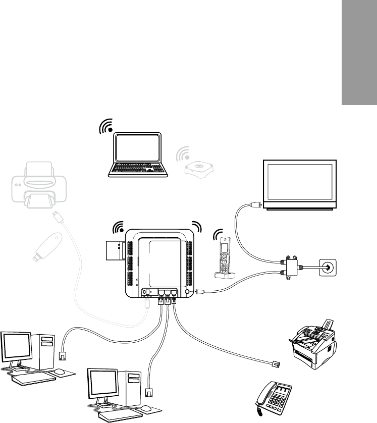
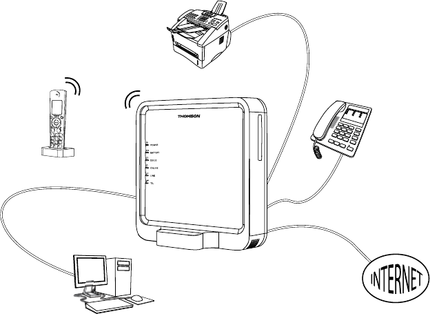
Connecting the Advanced Cable Gateway with other Devices
The Gateway, as illustrated below, has the ability to connect with a wide
variety of equipment that you may have including PCs, analog phone, etc...
printer
storage
computer (1)
computer (2)
analog
phone
fax
cable
splitter
TV
music
box
(For Future Use)
WiFi* computer
PC card
Handset
with
dock
Wireless
Connections
Te lephone
Connections
Cable
Connections
Ethernet
Connections
(For Future Use)
USB
Connections
RF
RF
RJ-45
RJ-45
USB
RJ-11
Advanced
Cable
Gateway
USB
22
Parts and Putting them Together
Connection Between Devices
This illustration shows a cable company that offers DOCSIS- and
PacketCable- compliant voice/data services.
1. How Does the Gateway Work?
The Advanced Cable Gateway provides high-speed Internet access as well
as cost-effective, telephone voice and fax/modem services for residential
subscribers over a CATV (cable TV) infrastructure. It can inter-operate with
the PacketCable compliant head end equipment and provide IP-based voice
communications.TheIPtrafccantransferbetweentheAdvancedCable
Gateway and DOCSIS compliant head end equipment. The data security
secures upstream and downstream communications.

23
Parts and Putting them Together
Assemble
2. What do you need to enjoy all services?
The Right Cable Company• :
Make sure your local cable company provides data services that use
cable TV industry-standard DOCSIS compliant and PacketCable
compliant technology.
Internet/Telephone Service Provider (ISP/TSP)• :
Your cable company provides you access to an Internet Service
Provider (ISP) and Telephone Service Provider (TSP).
The ISP is your gateway to the Internet and provides you with a
pipeline to access Internet content on the World Wide Web (WWW).
The TSP provides you with telephone access to other modems
or other telephone services over the Public Switched Telephone
Network (PSTN).
Check with your cable company to make sure you have everything you need
to begin.
Your cable company will know if you need to install special software or
re-congure your computer to make your cable internet service work for you.

24
Parts and Putting them Together
3. Establish an Internet Account
You need to contact your cable company to establish an Internet account
before you can use your Advance Cable Gateway.
You should have the following information ready (this can be found on the
sticker attached to the Gateway):
The Serial Number•
The Model Number•
The Cable Modem (CM) Media Access Control (MAC) Address•
The Terminal Adapter (EMTA) MAC Address•
SSID, WPA2-PSK Information •
Please verify the following with the cable company
Your internet account has been set up. •
(The Media Terminal Adapter will provide data service if the cable
account is set up but no telephone service is available.)
You have a cable outlet near your PC and it is ready for Cable Modem •
service.
Important Information:
Your cable company should always be consulted before installing a new
cable outlet.
Do not attempt any rewiring without contacting your cable company rst.
Note: It is important to supply power to the modem at all times.
Keeping your modem plugged in will keep it connected
to the Internet.
This means that it will be ready whenever you need it.
25
Parts and Putting them Together
Assemble
Connecting the Advanced Cable Gateway to a
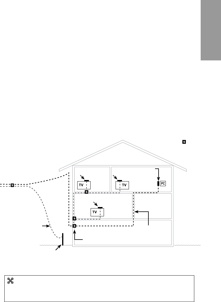
Figure 1
For optimum performance, be sure to connect your Advanced Cable
Gateway to the rst point the cable enters your home.
The splitter must be rated for at least 1GHz.
Grounding Wire
Grounding Rod
New Cable Wire
ACG
Modem
TV
converter
TV
converter
TV
converter
Splitters -
New 2-way splitter:
One leg goes directly to the ACG (modem)
One leg goes directly to the IN on the next splitter
Cable Drop
Single Computer
This section of the manual explains how to connect your Advanced Cable
Gateway to the ethernet port on your computer and install the necessary
software.
Please refer to Figure 1 (below) to help you connect your ACG Modem
for the best possible connection.
1. Attaching the Cable TV Wire to the Advanced Cable Gateway
LocatetheCableTVwire.Youmaynditbylocatingequipmentthatis
connected directly to the Cable TV wire such as:
a TV a Cable TV converter box or a VCR.
The Cable TV line will be connected to the socket which should be
labeled:
IN CABLE IN CATV CATV IN, etc.
The line will be coming out from under a baseboard, heater, or other location.
Refer to Figure 1 (below) for the wiring example.
26
Parts and Putting them Together
computer (2)
computer (1)
wall
outlet cable
connection
RF
RJ-45
RJ-45
Advanced
Cable
Gateway
Handset
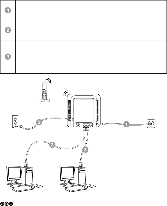
Ethernet Connection to One or Two Computers
Make the connections to the modem in the following sequence:
Connect one end of the coaxial cable to the cable connection on the
wall, and the other end to the CABLE connector on the Advanced
Cable Gateway.
Connect one end of the power cord into the 120V, 60Hz, 0.5A socket
on the Advanced Cable Gateway and the other end into the power
plug in the wall.
Connect one end of the Ethernet cable (straight-wired, see below) to
the Ethernet port on the back of your computer and the other end to
the ETHERNET port on the Advanced Cable Gateway.
Note: The Gateway is equipped with two Ethernet ports, making
additional equipment unnecessary.
Note: Make sure that the Ethernet cable is straight-wired (not “null” or
crossover-wired).
However, you will need a crossover-type cable if you are connecting the
Gateway to a hub or a hub within a port switch that provides the same
function.
27
Parts and Putting them Together
Assemble
Connect one end of the coaxial cable to the cable connection on the
wall, and the other end to the CABLE connector on the Advanced
Cable Gateway.
Connect one end of the power cord into the 120V, 60Hz, 0.5A socket
on the Advanced Cable Gateway and the other end into the power
plug in the wall.
Connect one end of the Ethernet cable (straight-wired, see below) to
the Ethernet port on the back of your computer and the other end to
the ETHERNET port on the Advanced Cable Gateway.
Note: The Gateway is equipped with two Ethernet ports, making
additional equipment unnecessary.
If you want to create hard wired connections to the ACG for more than
two computers, you will need to purchase a Hub (Switch) for that purpose
and the cabling necessary for those additional connections. Although a
10BaseT Hub or Switch can be used, it is not recommended. A 100BaseT
Hub or Switch is recommended. Follow the installation guidelines that
accompany this equipment.
Connecting More Than Two Computers
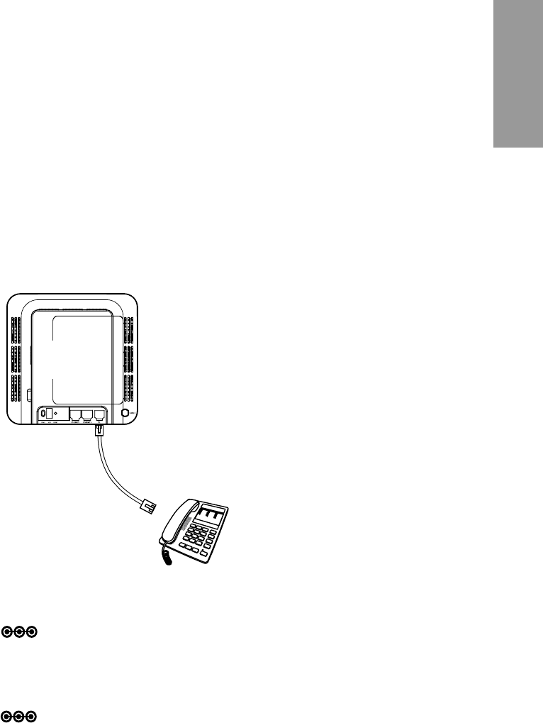
Telephone or Fax Connection
When properly connected, most telephone devices can be used with the
Advanced Cable Gateway. Here is how to make that connection
Note: If you have any questions concerning telephone connection, please
contact your service provider.
Note: There is only one TEL connection available on the rear panel of the
AGC.
analog
phone
Advanced
Cable
Gateway
Connect a standard phone line
cord directly from the phone (fax
machine, answering machine, caller
ID box, etc.) to the TEL port on the
Advanced Cable Gateway.
To make a normal telephone call,
pick up the handset; listen for a dial
tone, then dial the desired number
using this new connection. For
services such as call waiting, use
the hook switch (or FLASH button)
to change calls.
to the Advanced Cable Gateway

28
Activating Services
Activating the Advanced Cable Gateway
After installation of the Advanced Cable Gateway, each time you turn it on
(each time the modem is reconnected to the power), it goes through several
steps before it can be used.
Each of these steps is represented by a different pattern of ashing lights on
the front of the modem.
Lights Guide
Legend
ON LED is on. SLOW BLINK LED is blinking slowly.
OFF LED is off. FAST BLINK LED is blinking quickly.
X
LED can be in any
state (on, off or
blinking).
IfDS/US,ONLINE,andLINKledsashsimultaneouslyitmeanstheAdvanced
Cable Gateway is automatically updating its system software. Please wait for
the lights to stop ashing. You cannot use your modem during this time. Do
not remove the power supply or reset the Advanced Cable Gateway during
this process.

29
Activate
Activating Services
LED LABEL Power
Battery
( LED desc.
when battery
is inserted )
DS/US ONLINE LINK TEL
Boot Up
Operation
Power On during 0.25s OFF ON ON ON ON ON
From Power On to System
Synchronization complete ON ON SLOW
BLINK
SLOW
BLINK OFF OFF
Before DS scanning:
during 1s ON ON ON ON X* OFF
DOCSIS Start-Up Operation
Note 1
DS scanning & acquiring
SYNC ON ON FAST
BLINK OFF X OFF
From SYNC completed,
receiving UCD to ranging
completed
ON ON SLOW
BLINK OFF X OFF
DHCP ON ON ON FAST
BLINK X OFF
cong le download ON ON ON SLOW
BLINK X OFF
Registration & BPI
initialization ON ON FAST
BLINK
FAST
BLINK X OFF
Operational (NACO On) ON ON ON ON X OFF
Operational (NACO Off) ON ON ON OFF X OFF
Telephone
Provisioning ON ON ON ON XFAST
BLINK
Registered ON ON ON ON X ON
Not available ON ON ON ON X OFF
LAN Active
No Ethernet or WiFi Link ON ON ON ON OFF X
Ethernet or WiFi Link ON ON ON ON ON X
Tx/Rx Ethernet or WiFi
Trafc ON ON ON ON SLOW
BLINK X
ACG in dect association
mode = Page button has
been pressed for more
than 12s
ON ON ON ON FAST
BLINK X
* “X” indicates that this LED is not used to show the state of operation described on this line.
Check in this column for the state in which this LED is ON.
Note 1- “Flash” indicates a CM or EMTA initialization process in progress.
A “Flash” that does not stop indicates an initialization error.
Note 2- During an AC Power Failure with a bad battery, the operation of the device
may not be possible due to lack of battery power; all LEDs may be “Unlit”.

30
Activating Services
LED LABEL Power
Battery
( LED desc.
when battery
is inserted )
DS/US ONLINE LINK TEL
EMTA Normal Operation
AC Power Good
Good Battery
all lines
On-
Hook ON
ON
CM Normal Operation
CM Normal Operation
CM Normal Operation
ON
1 line
or more
Off-Hook ON SLOW
BLINK
Low Battery
all lines
On-
Hook ON
SLOW
BLINK
ON
1 line
or more
Off-Hook ON SLOW
BLINK
Bad Battery
all lines
On-
Hook ON
OFF
NOTE 2
ON
1 line
or more
Off-Hook ON SLOW
BLINK
AC Power Failure
Good Battery
all lines
On-
Hook FLASH
OFF
OFF OFF
OFF
ON
1 line
or more
Off-Hook FLASH SLOW
BLINK
Low Battery
all lines
On-
Hook FLASH
SLOW
BLINK
ON
1 line
or more
Off-Hook FLASH SLOW
BLINK
Bad Battery
all lines
On-
Hook OFF
OFF
NOTE 2 NOTE 2 NOTE 2 NOTE
2
1 line
or more
Off-Hook OFF
SW Download
Operation
During Software
download & while
updating the FLASH
memory
ON ON SLOW
BLINK
SLOW
BLINK
SLOW
BLINK X
Restore
to Factory
Settings
ACG is powered off.
Press the Page button
while powering on the
ACG. Hold the page
button for 5s
Turn on all LEDs when factory RESET starts
EMTA Reset
(soft Reset)
Upon pressing the Rest
button LEDs behave as if the device is powering up
31
Activate
Activating Services
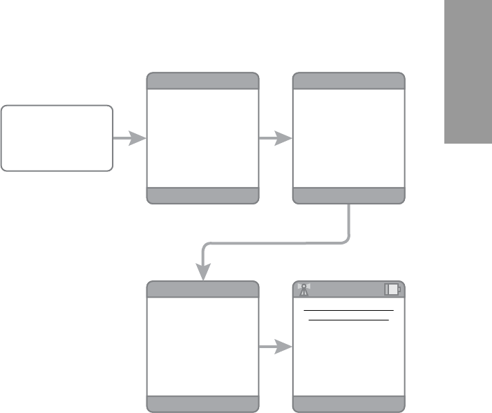
Self Installation
To enjoy all Gateway services (multi-line capability, access to address book
etc…),youmustrstsetupyourGateway.
To ease the installation, your DECT Handset is programmed with the self
installation guide, which will lead you “step-by-step” through the whole
installation process.
Starting the Self Installation
Check all connections for the Advanced Cable Gateway and the 1.
Handset. Turn the Handset ON.
Wait until you see instructions on the Handset. 2.
Thestandardmessageowisdescribedinthegurebelow.
If you are having troubles with this installation, please refer to the
Handset user guide pages xx to xx.
You are now ready to use the Advanced Cable Gateway. Enjoy!3.
Please wait while we test
your cable connection
Continue
Registration
Connection was successful.
Press ‘Continue’ to register
your phone with the server.
This is a one-time process.
Please wait while we
register your phone.
Users Menu
Activate your Comcast
Digital Voice service
Oct 14, Sat 10:00
Power On
32
Activating Services
Wi-Fi Connection
The Advanced Cable Gateway is ready to support Wi-Fi and comes with a
card. Follow these instructions for installation:
FRONT of WiFi card
(this side must face you
during insertion)
BACK
of WiFi card
Ensure the power cord is unplugged.
Remove the protective cover over the
WiFi slot located on the upper right
hand side of the gateway.
Make certain that the front of the
WiFi card is facing you.
Insert the WiFi card in the slot as far
as it will go without forcing it.
Plug the power cord into the wall
socket.
Cover for WiFi slot removed
WARNING: The Gateway must be
unplugged from the wall
socket before you attempt
to install the WiFi card.
Light Indicators on the Front Panel
After the card is inserted and the ACG
Gateway is plugged back into the power
outlet, you will know that the connection is
successful when the PWR LED on the front of
the Gateway shows a green light.
Also
WhenyourstturntheGatewaybackon,the
LINK LED will blink a green light - fast;
when the card connects to the network
sucessfully, it will blink - slowly.
Slot for WiFi
with
cover removed

33
Activate
Activating Services
Wireless Internet Access for Your Computer
WiFionyouAdvancedCableGatewayispreconguredwithanetworkname
(SSID) and WPA key (a security password to prevent others access to your
wireless network). This information is printed on the label on the outside of
your ACG as shown in the following diagram:
In order to take advantage of the WiFi connection available to you with
the Gateway you will need to setup your computer. Setup will be different
depending on the year, brand, model and installed software of your
computer. Please follow the instructions received with you computer that
explain how to connect to a wireless network. If you are using a recent
version of Microsoft Windows, one of the following methods may apply
(consult your computer/laptop instructions if one of these methods does not
work)
Method 1:
Click on “Wireless” icon in the bottom right hand portion of your •
screen
Select,”View Wireless Networks”•
Highlight “SSID” from the list and press “Connect”•
When prompted, enter the WPA key twice and press “Connect”•
Method 2:
Go to “Start” - “Control Panel” - “Network Connections”•
Double click “Wireless Network Connections”•
Highlight “SSID” from the list and press “Connect”•
When prompted, enter the WPA key twice and press “Connect”•
Method 3:
Go to “Start” - “Network Connections”•
Double click “Wireless Network Connections”•
Highlight “SSID” from the list and press “Connect”•
When prompted, enter the WPA key twice and press “Connect”•
WPA
SSID
S/N 87003 - 8174B0018
E-MTA MAC@ 00D059E132E5
MODEL : ACG905--C
CM MAC@ 00D059E132E4
Rating: 120V AC, 60Hz, 0.5A
SSID: COMCAST-ACG-32E4
WPA key: 12340678C9
HW version: 05
Made in China for THOMSON
FCC ID WBJ ACG905C001THFR
I.T.E.
17GM E198937
34
Activating Services
Web Conguration
To make sure that you can access the Internet successfully, please check the
following:
Make sure the Ethernet connection between the Advanced Cable •
Gateway and your computer is OK.
For wireless networking (see page ??),youwillneedaWiFi-certiedwireless
client adapter for each computer you want to connect wirelessly.
If your computer does not have WiFi capability, you should equip it with a
WiFi accessory (norm 802.11b/g).

35
Activate
Activating Services
Accessing the Web Conguration
The Advanced Cable Gateway (ACG905) offers local management capability
throughabuiltinHTTPserverandanumberofdiagnosticandconguration
webpages.Youcancongurethesettingsbywayofthewebpageandapply
them to the device.
OnceyourhostPCisproperlycongured;pleaseproceedasfollows:
Start your web browser and 1.
type
http://cable.cong/
After connecting to the site, 2.
you will be asked to enter
username and password.
By default,
the Login Name is: ______
(leavetheeldblank)
Password is: admin
If you log in successfully, the main
webpage will appear.
Connect to 192.168.100.1 ? X
Thomson
User name:
Password:
Remember my password
OK Cancel