TransCore 76007 FHSS TRANSCEIVER MODULE User Manual M6e Transcore Developer s Guide
TransCore FHSS TRANSCEIVER MODULE M6e Transcore Developer s Guide
UserManual.wiki
>
TransCore
>
76007 User Manual
>
Users Manual
Contents
1.
Users Manual
2.
User Manual 1
3.
User Manual 2
4.
User Manual 3
5.
User Manual 4
Users Manual
Navigation menu
Upload a User Manual
Namespaces
Wiki Guide
HTML
PDF
Info
Views
User Manual
Discussion / Help
Navigation
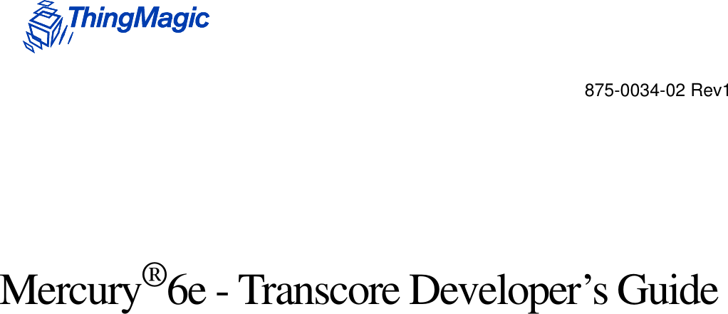
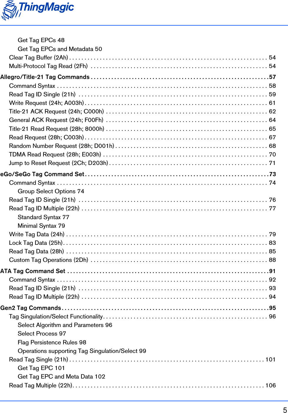
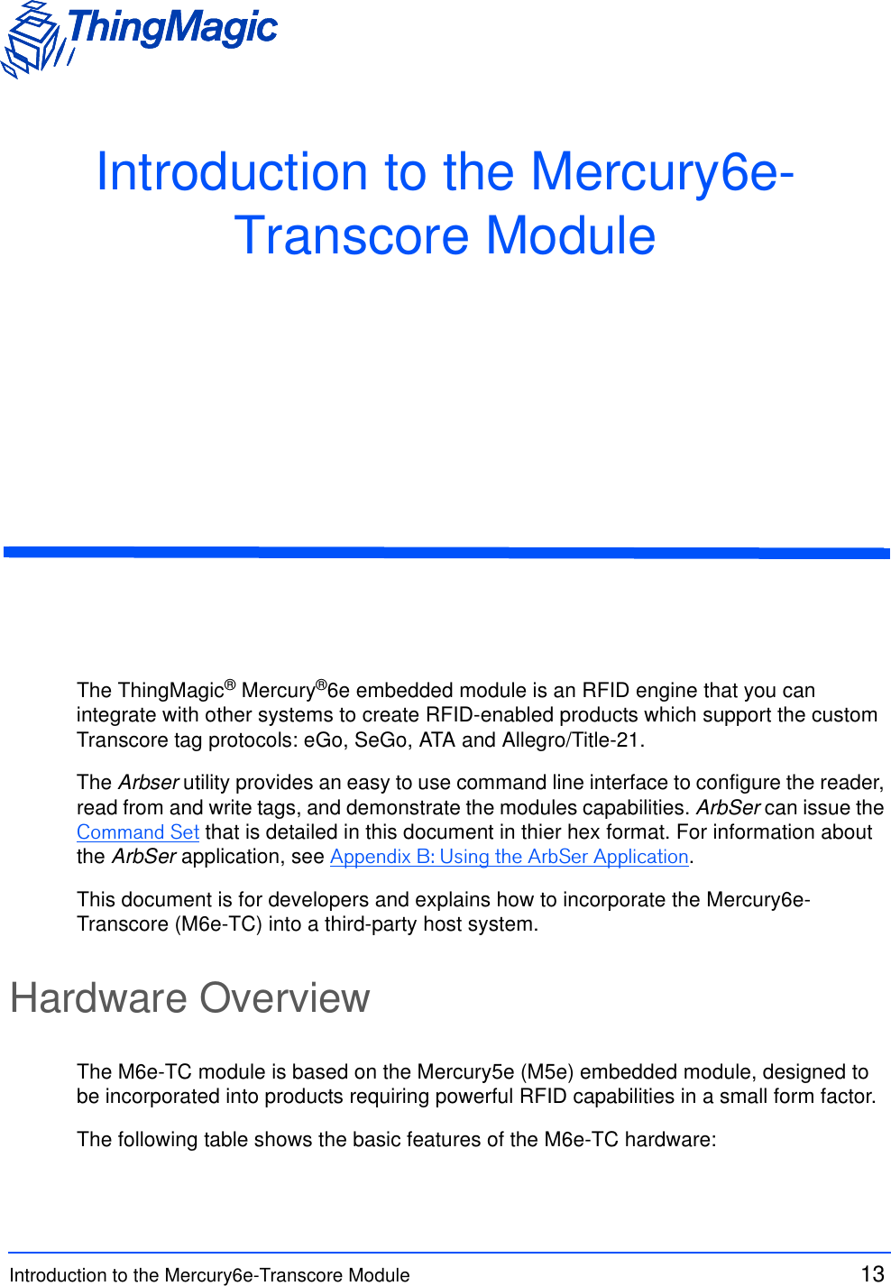
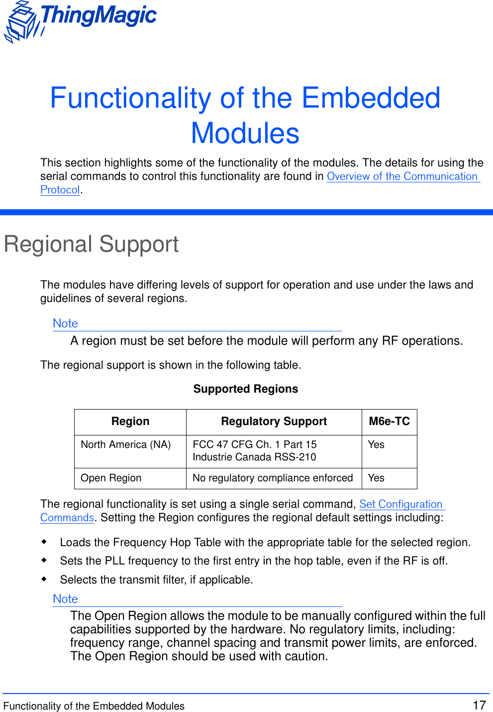
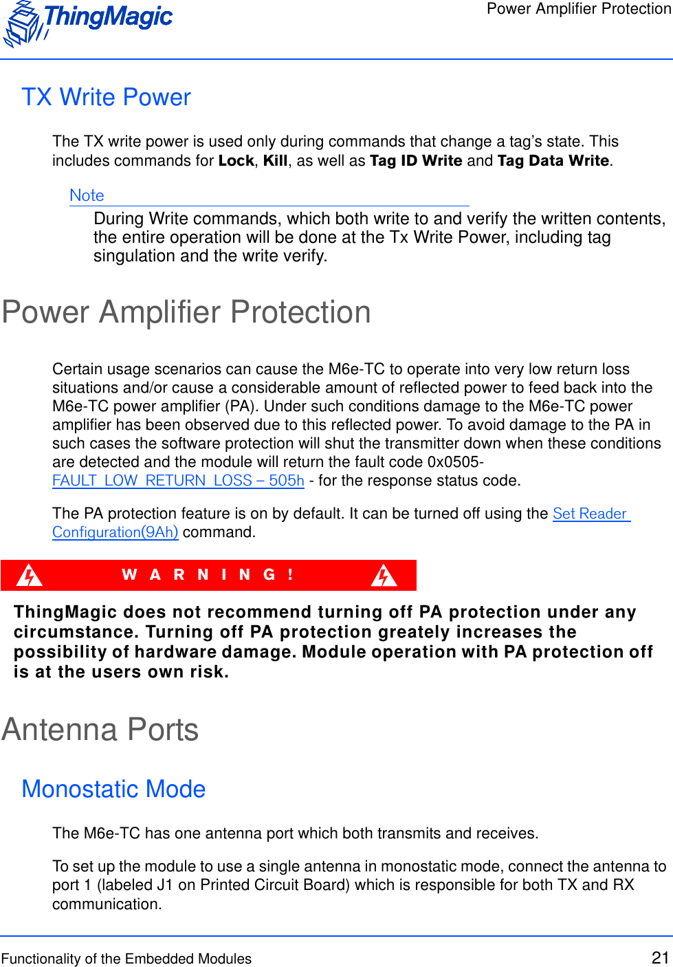
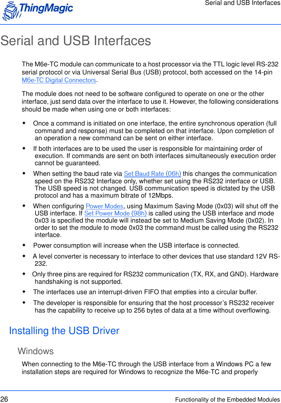
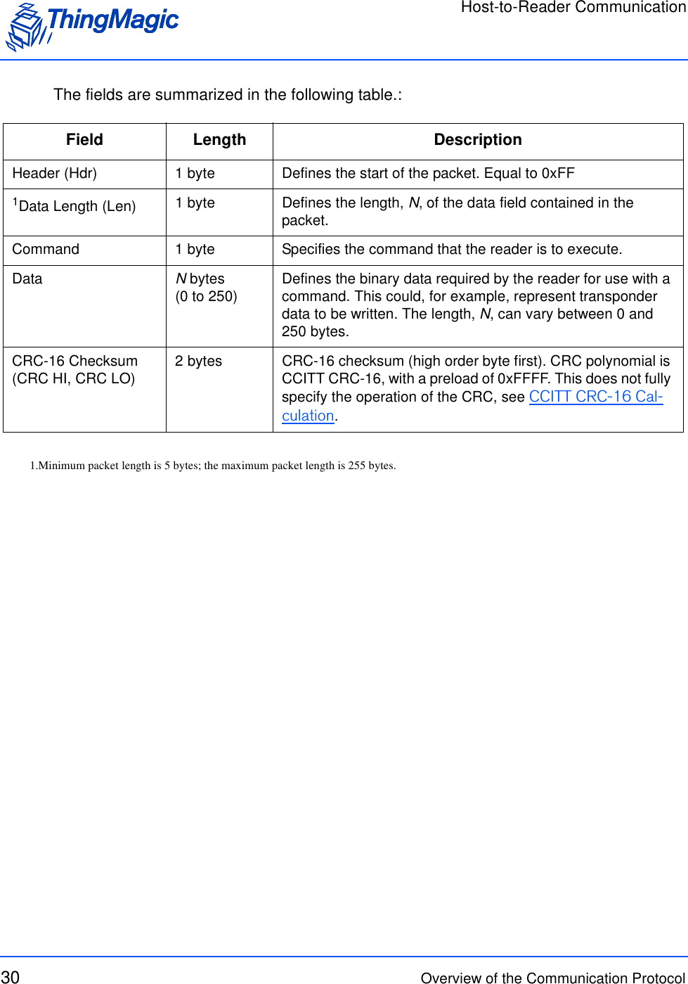
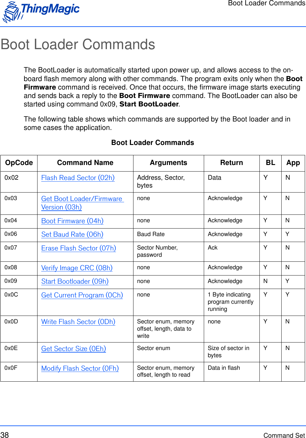
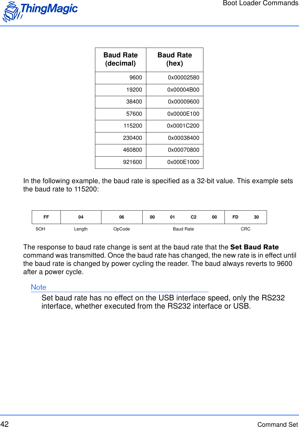
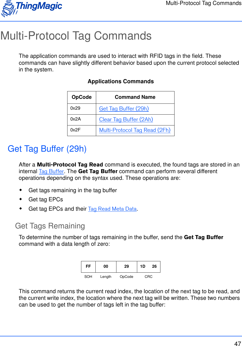
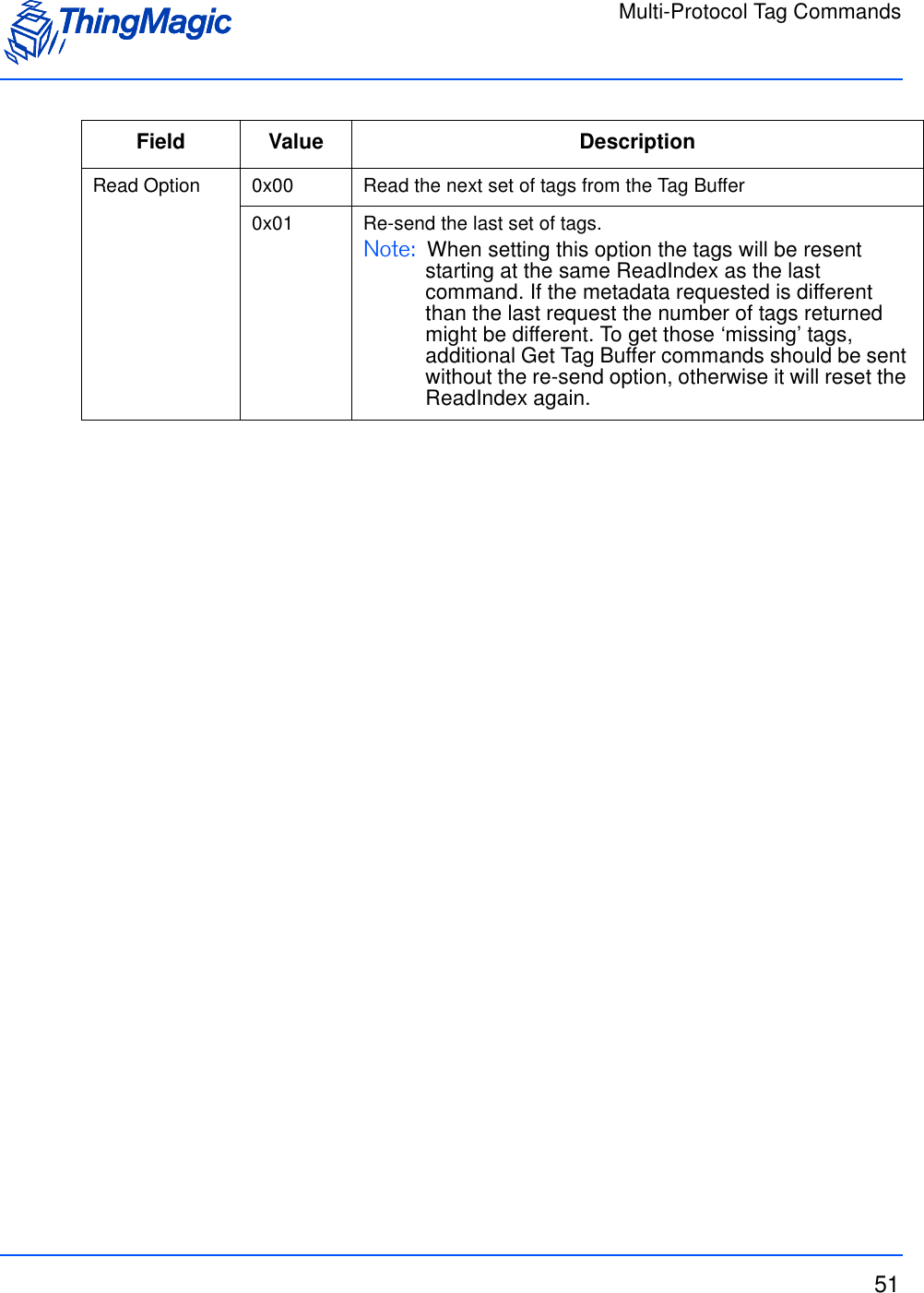
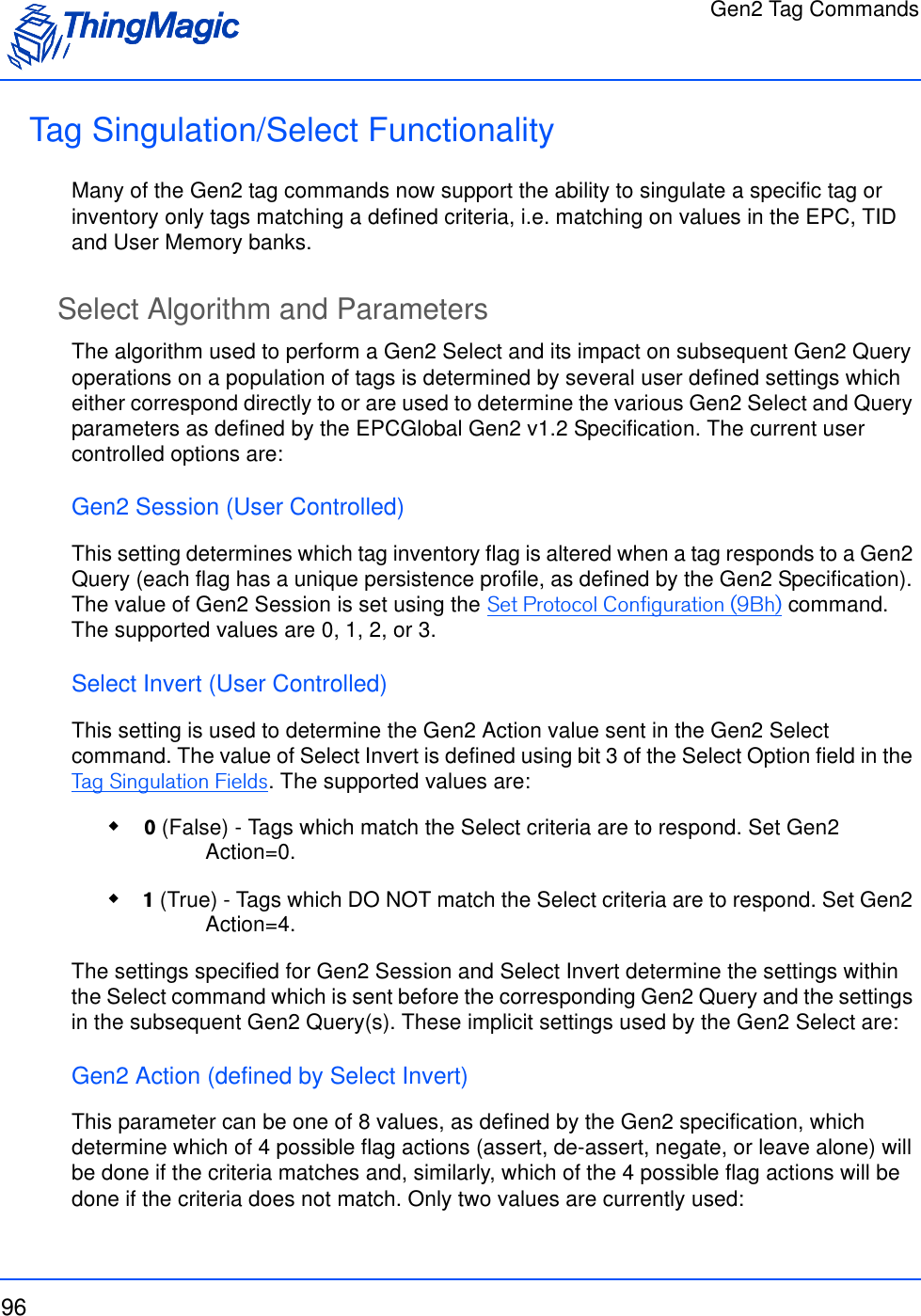
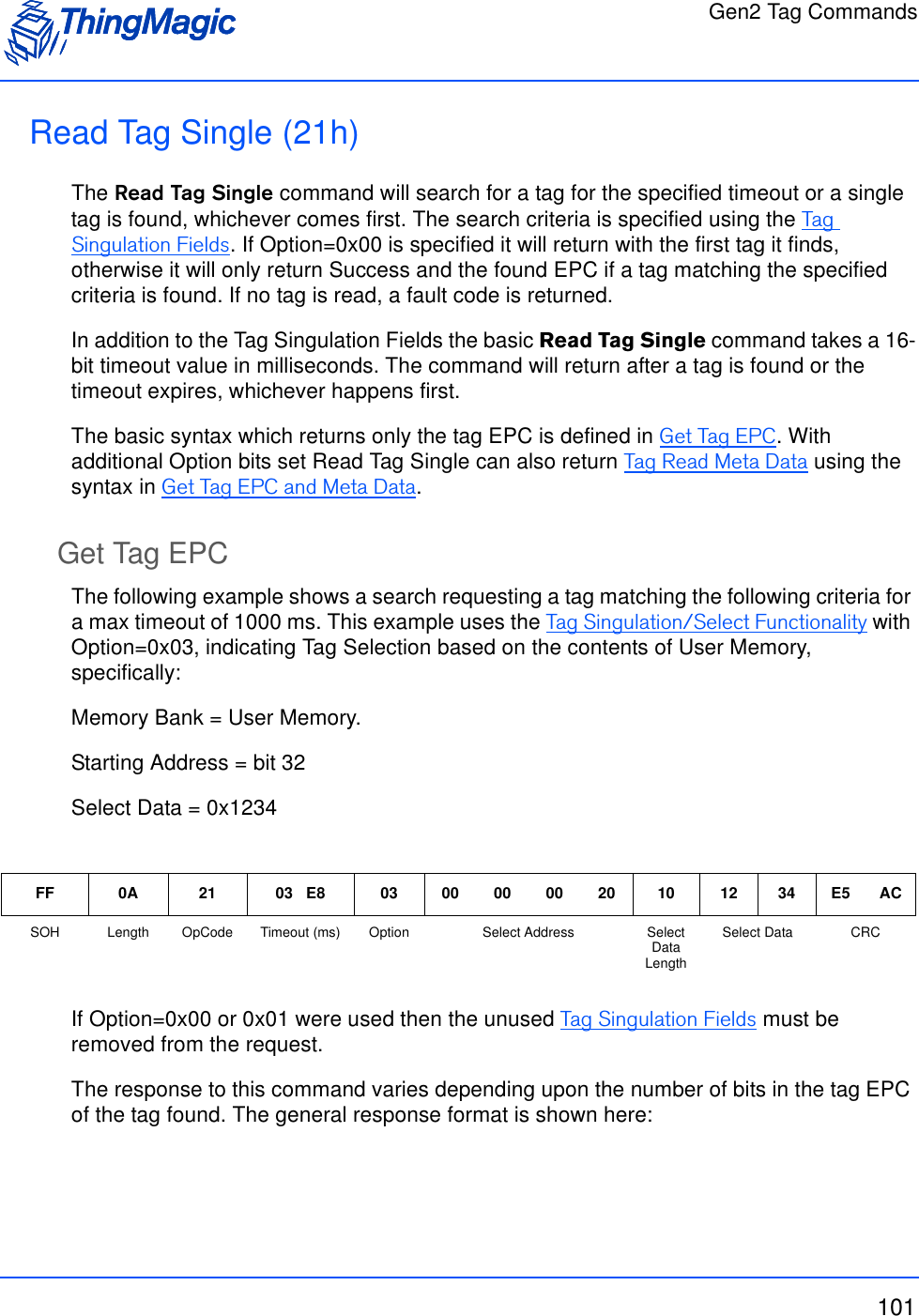
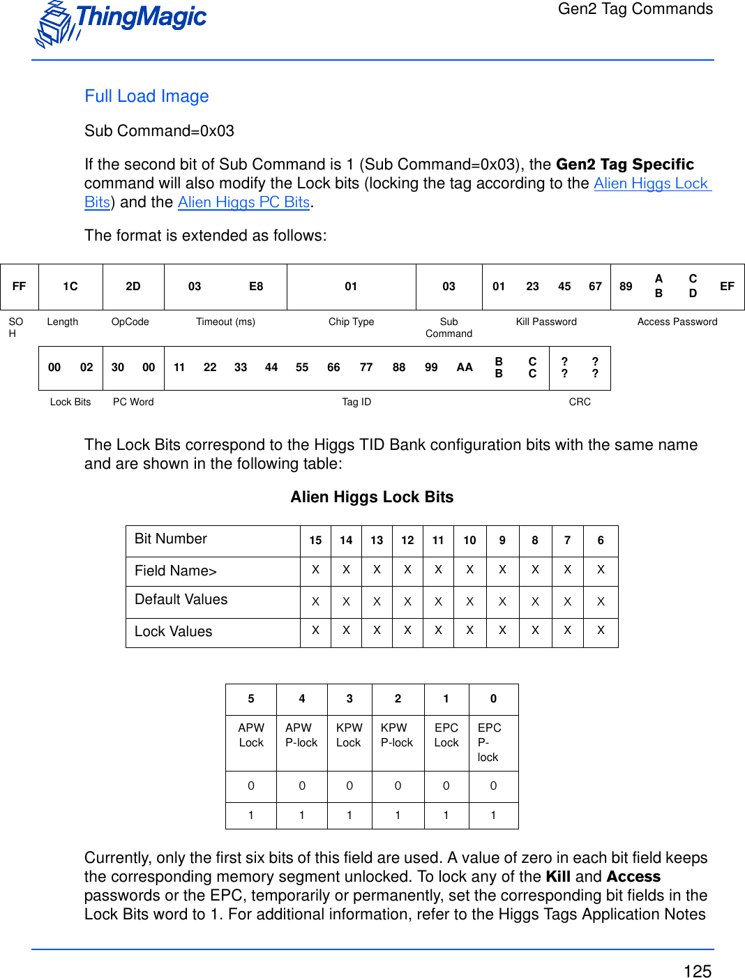
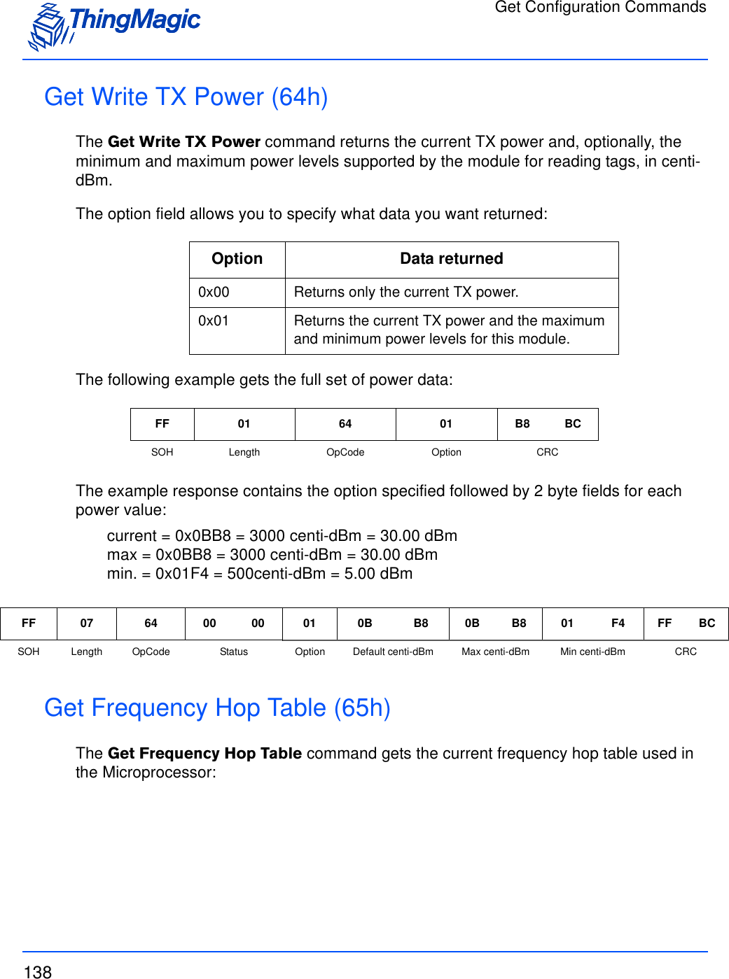
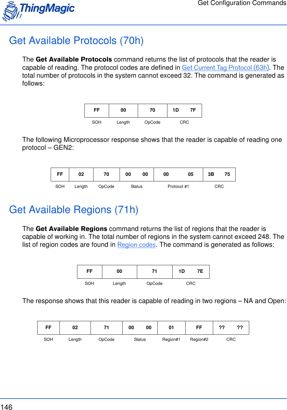
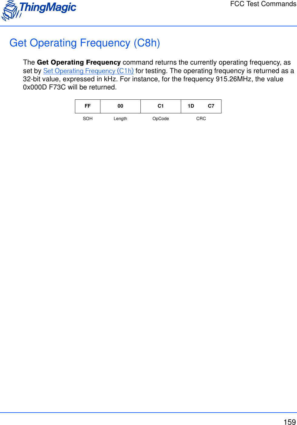
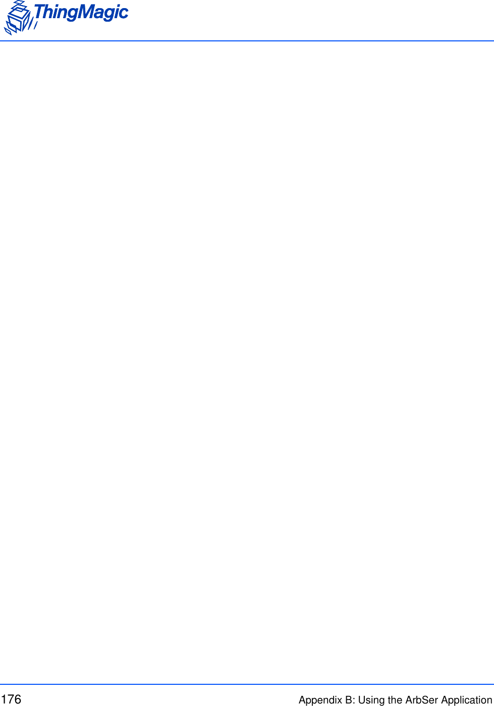
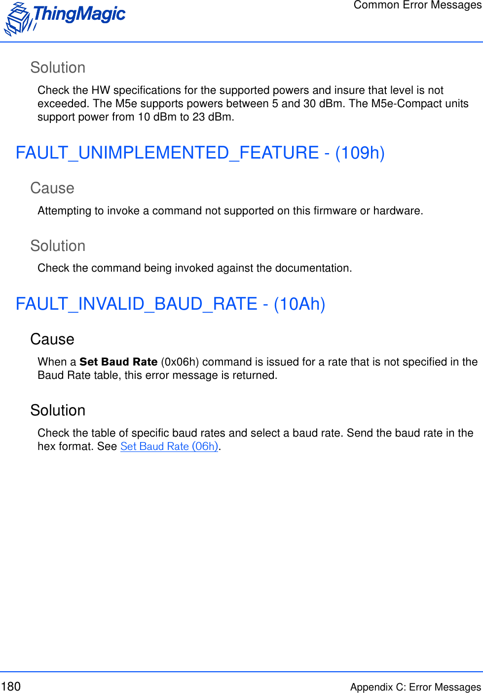
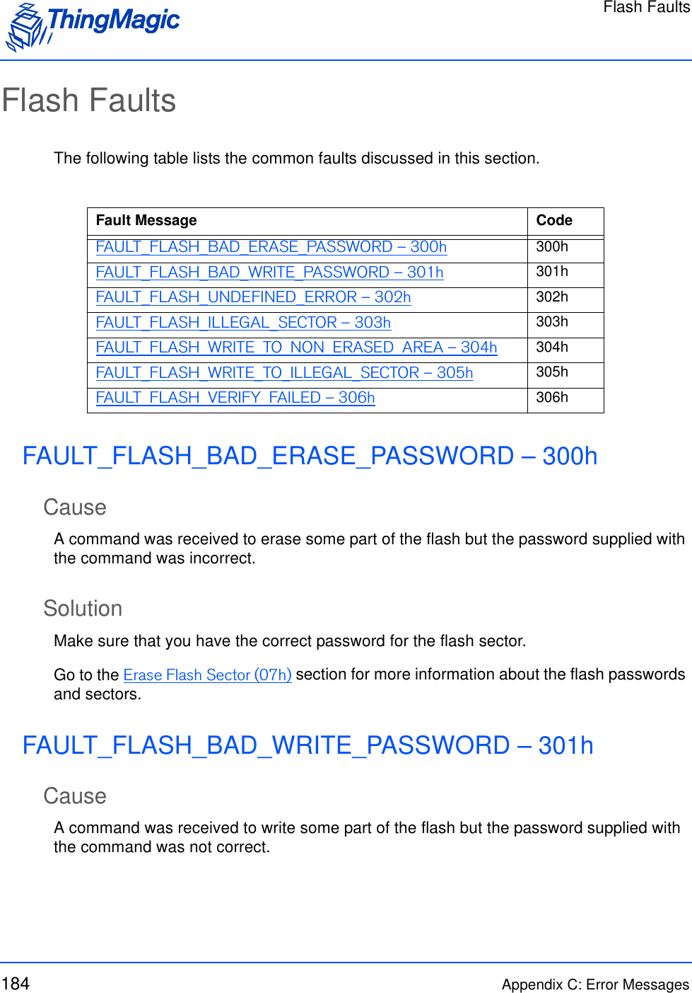
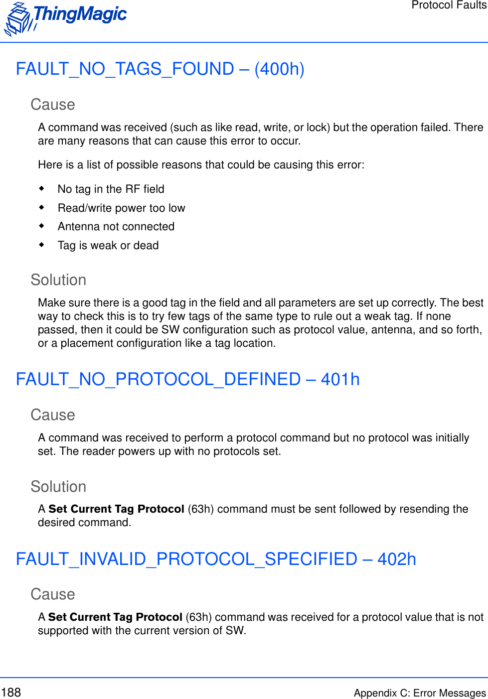
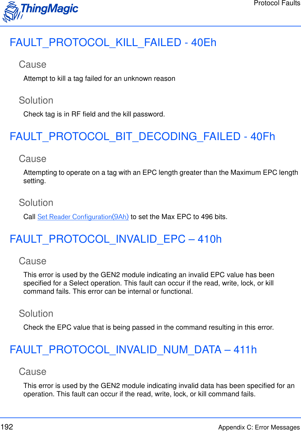
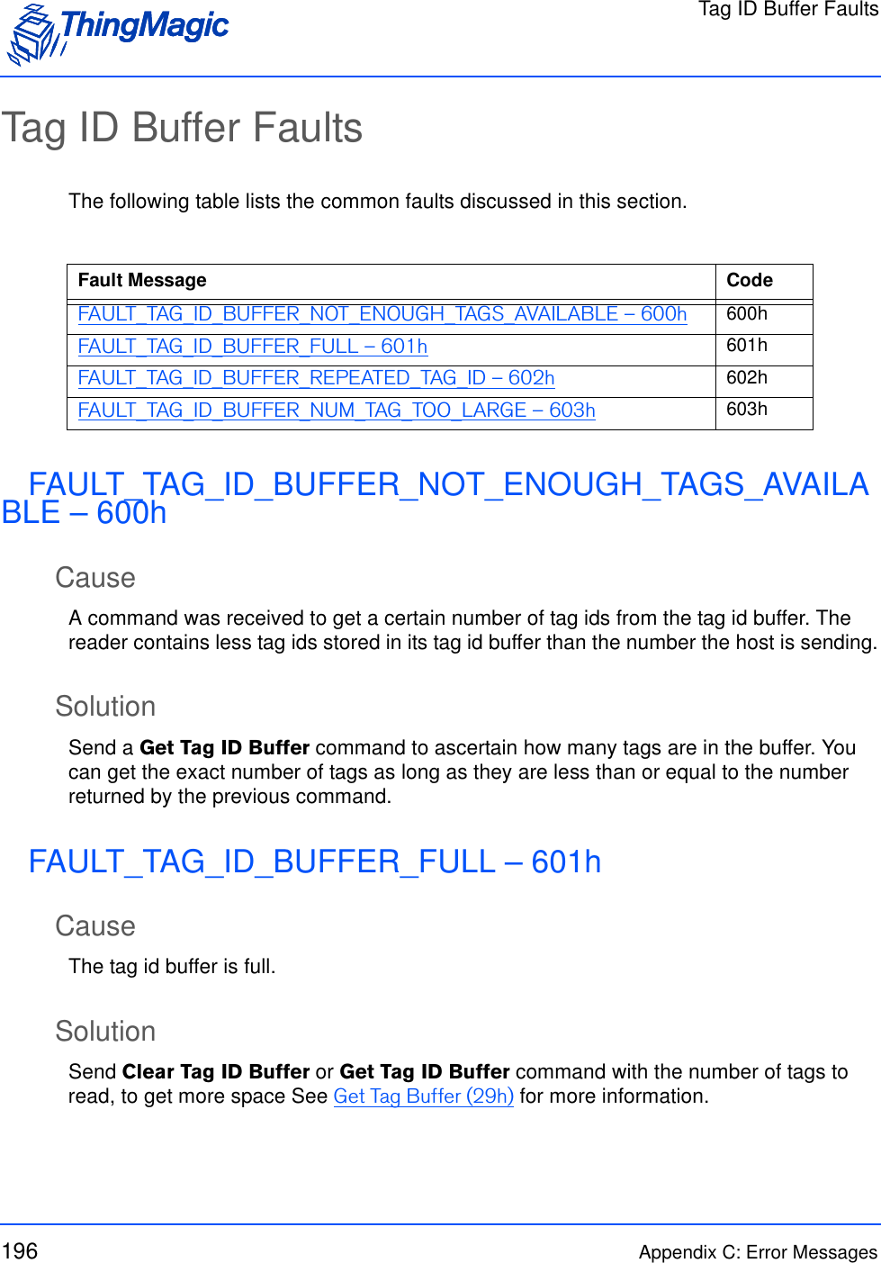
![Flash Memory24 Functionality of the Embedded ModulesTag Read Meta DataWhenever a Tag entry is placed in the buffer, it uses up a single entry with the EPC section containing the maximum EPC length number of bits, regardless of the actual EPC size of the tag read. The extra bits in the entry are padded with trailing zeros.After the Multi-Protocol Tag Read command finishes, it places all of the found tags into the Tag buffer, and then returns the number of tags found to the user. Only unique tags read on each antenna are added to the Tag buffer; none of the entries show repeated Tag EPCs. Repeated reads on an antenna will cause the Read Count field to be incremented for that tag entry. Multiple Get Tag Buffer commands must be sent to read out the Tags. The Tag buffer acts as a First In First Out (FIFO) — the first Tag found by the reader is the first one to be read out. See Get Tag Buffer (29h).The Tag buffer is reset only when the Clear Tag Buffer command is sent. See Clear Tag Buffer (2Ah). This allows multiple Multi-Protocol Tag Read commands to be used to acquire one consistent tag buffer set. Flash MemoryThe M6e-TC has on-board flash memory. This flash is divided into four different sectors of varying sizes. Table 4 shows the memory map for the M6e-TC. Only sector 0x03 is set aside for user data and the other sectors are used by the application FW. The flash sector utilities simplify the interface providing a means to develop interfaces that work across these platforms. Meta Data Field DescriptionAntenna ID The antenna on with the tag was read.Read Count The number of times the tag was read on [Antenna ID]. Timestamp The time the tag was read, relative to the time the command to read was issued, in milliseconds. If the Tag Read Meta Data is not retrieved from the Tag Buffer between read commands there will be no way to distinguish order of tags read with dif-ferent read command invocations. Frequency The frequency on which the tag was readRFU Reserved for Future Use - ThingMagic OnlyLQI/RSSI The receive signal strength of the tag response.Protocol ID The tag’s Protocol ID as defined by the Tag Protocol IDs table](https://usermanual.wiki/TransCore/76007.Users-Manual/User-Guide-1204374-Page-24.png)
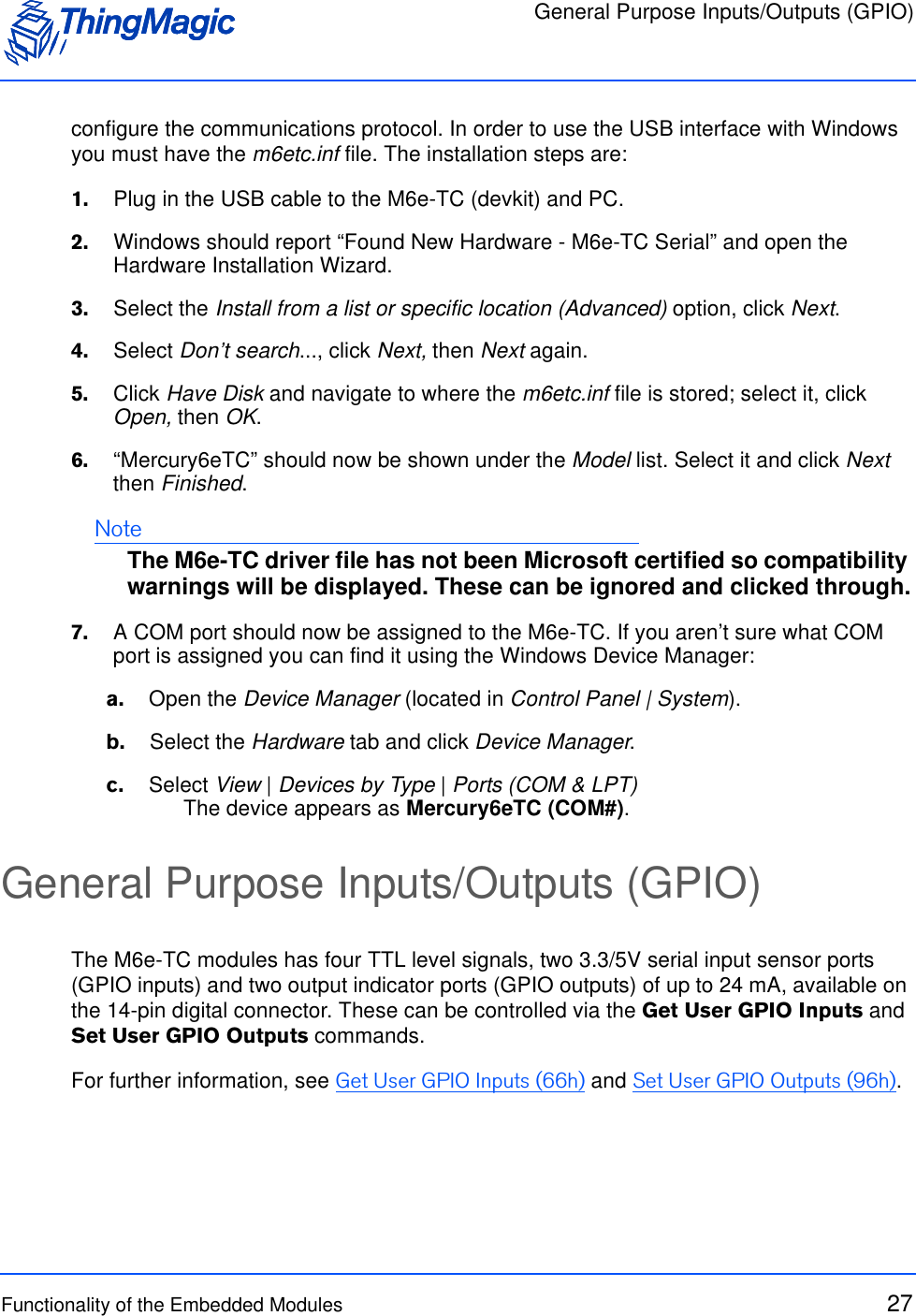
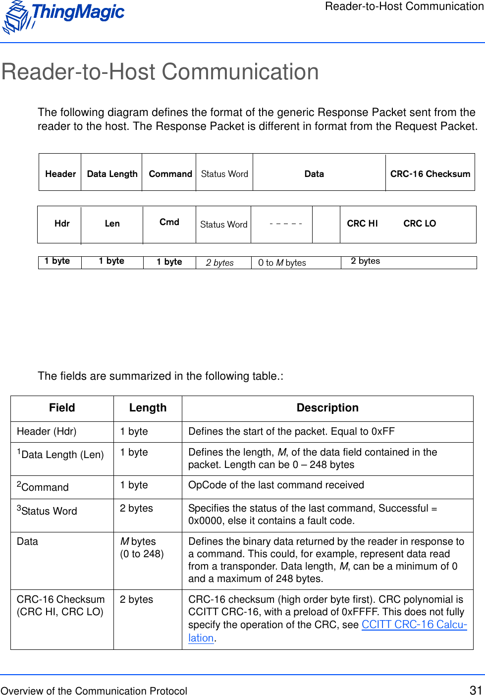
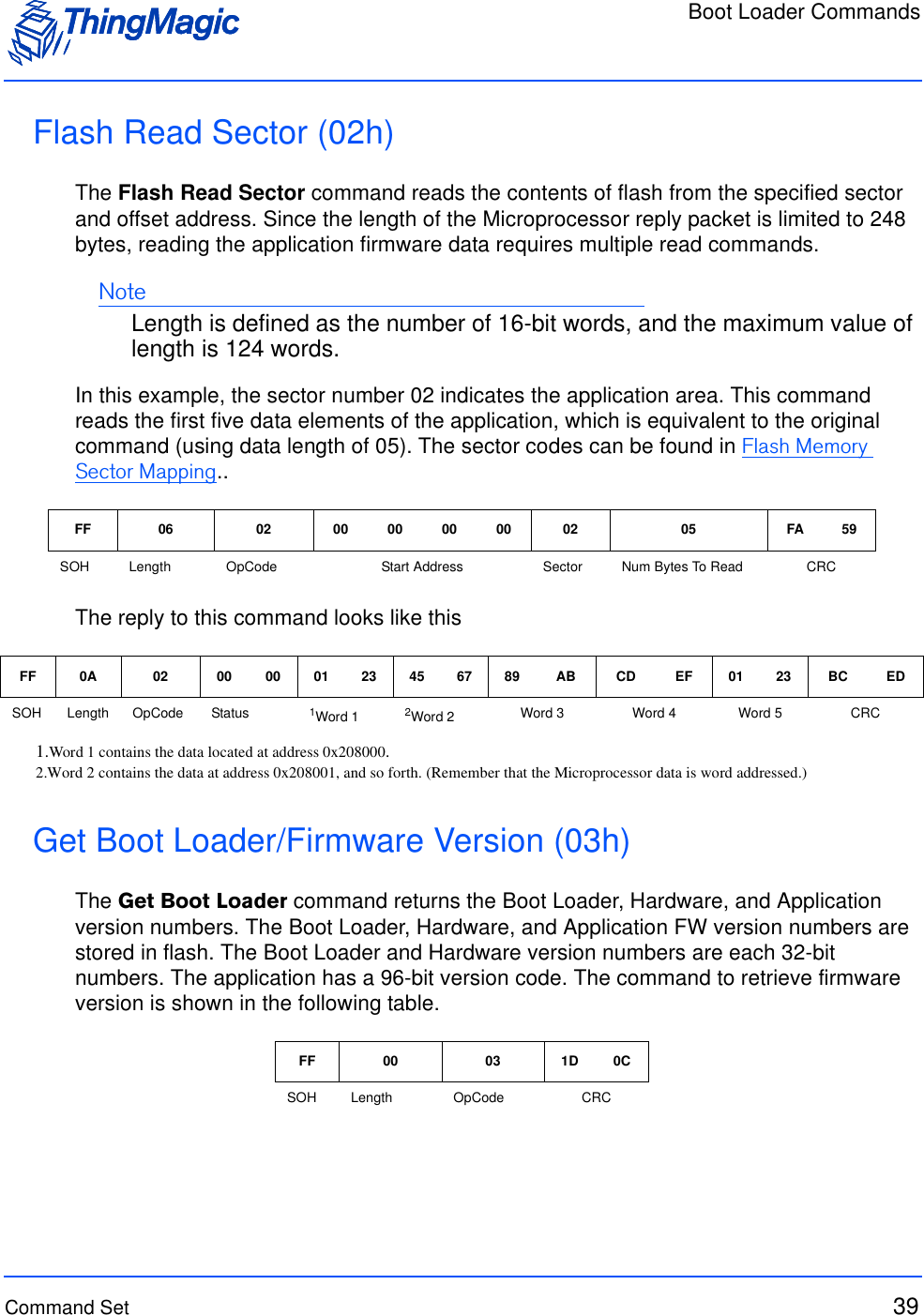
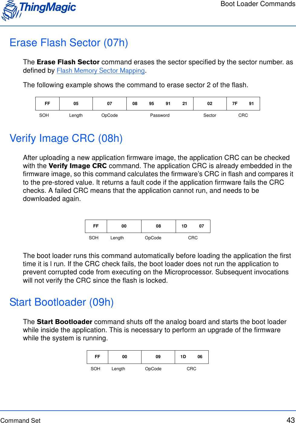

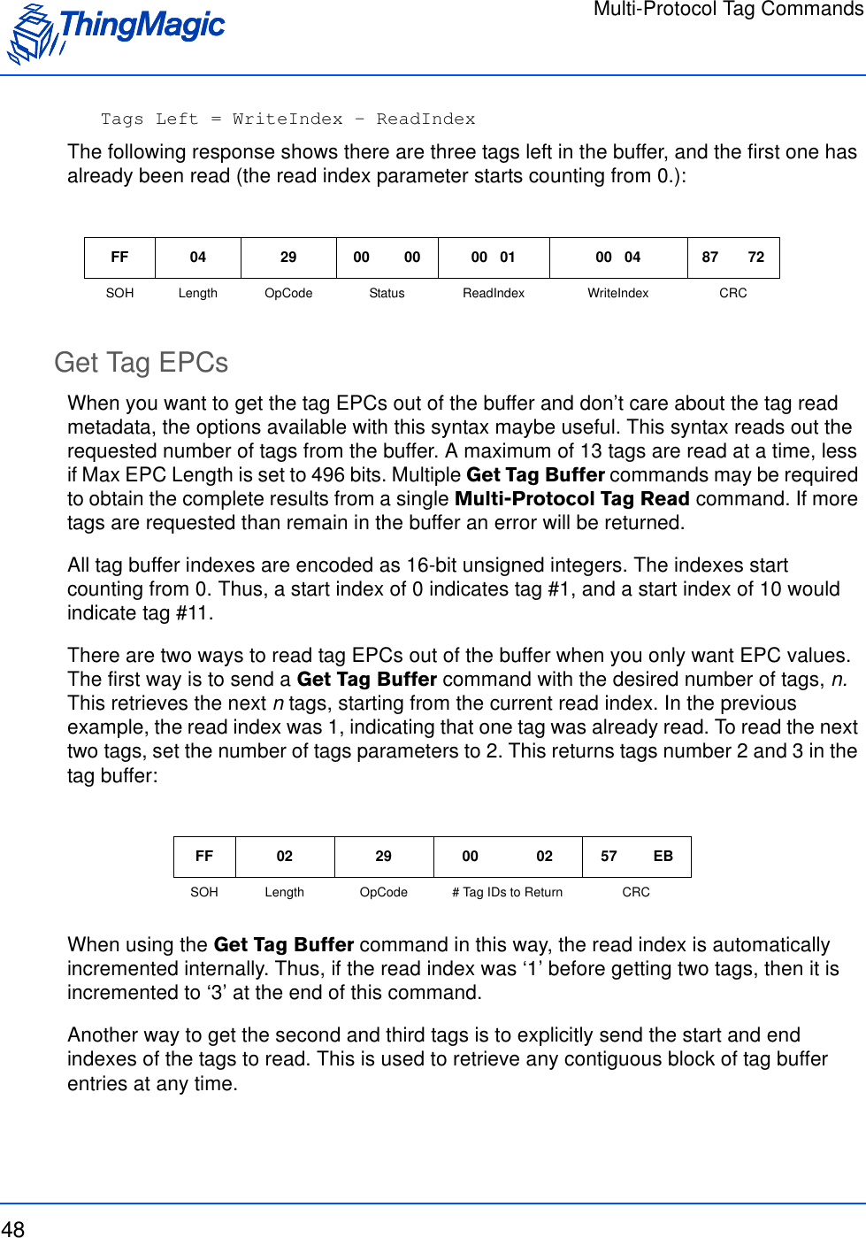
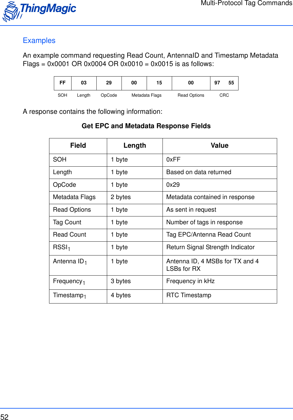
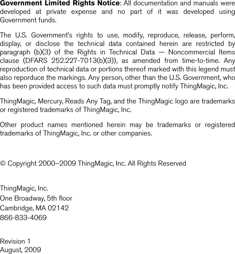
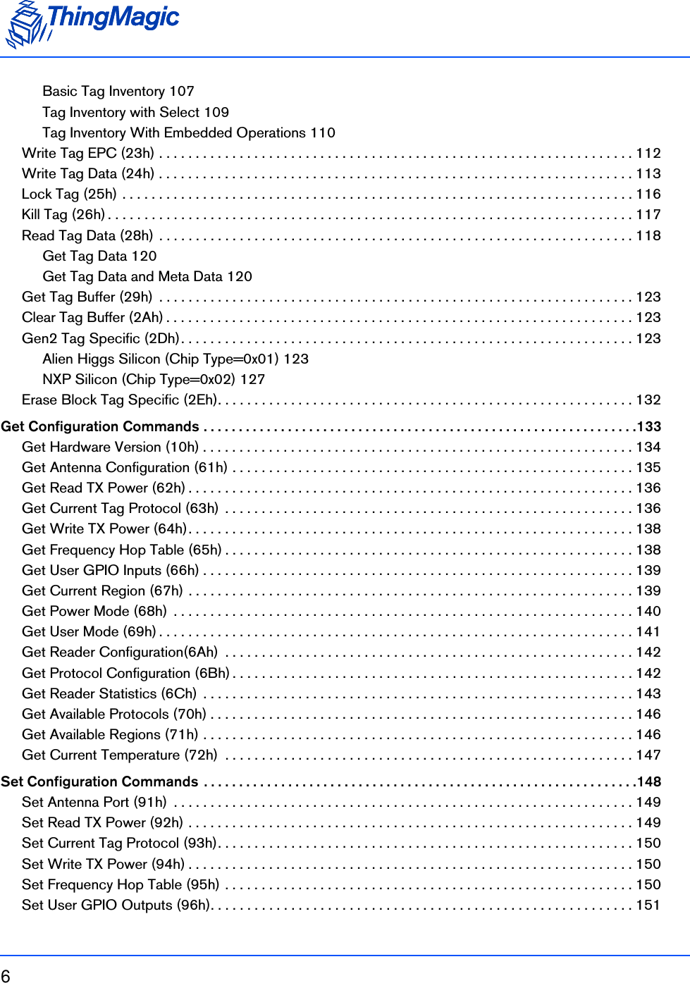
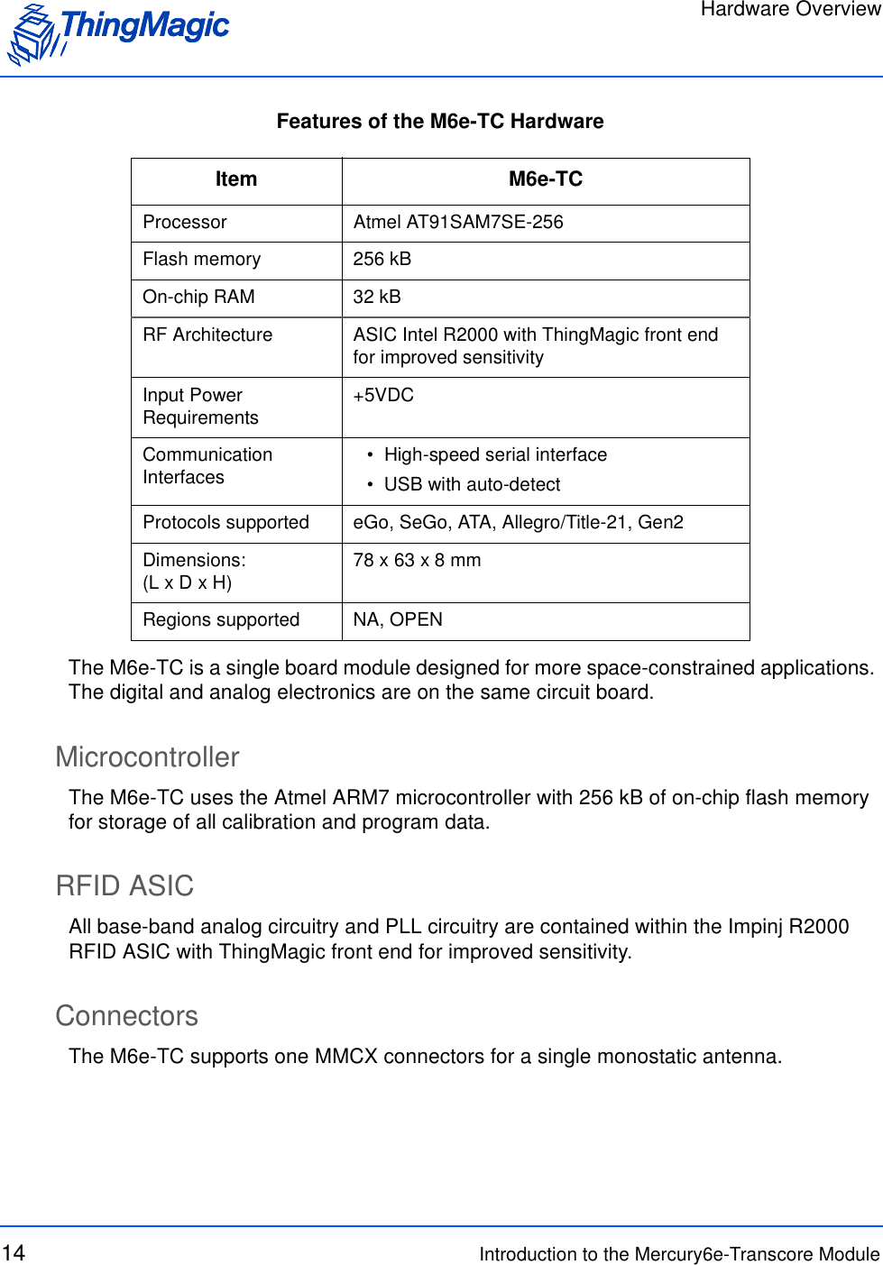
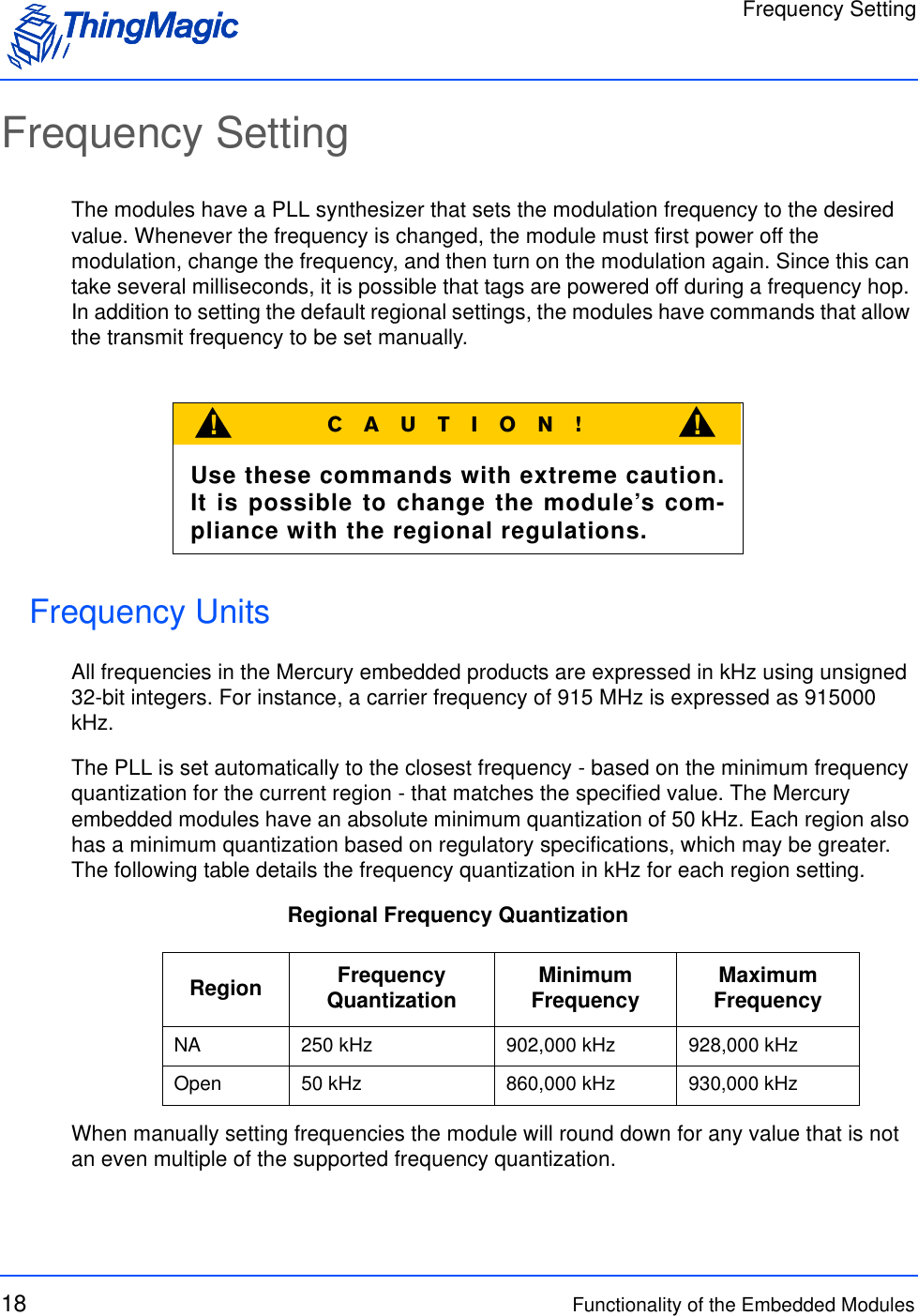
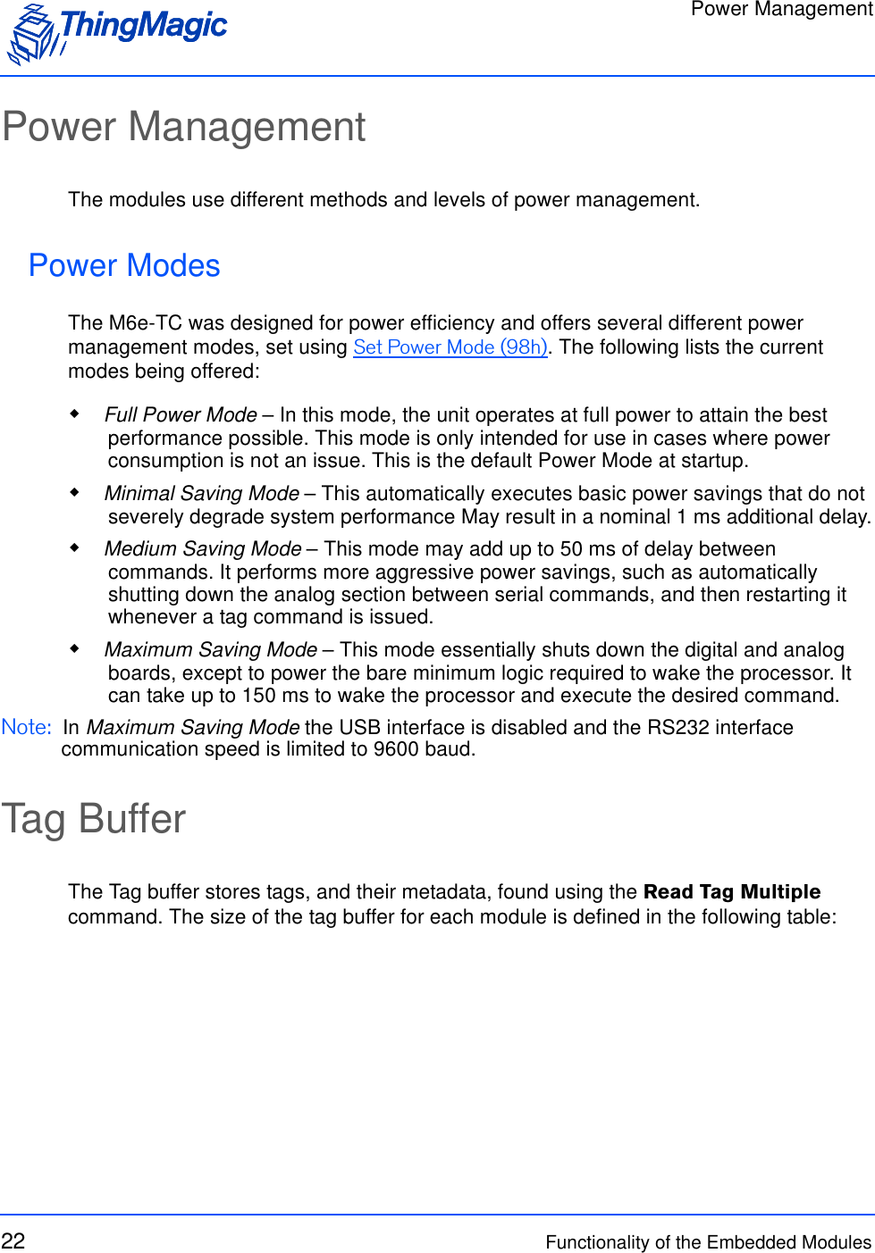
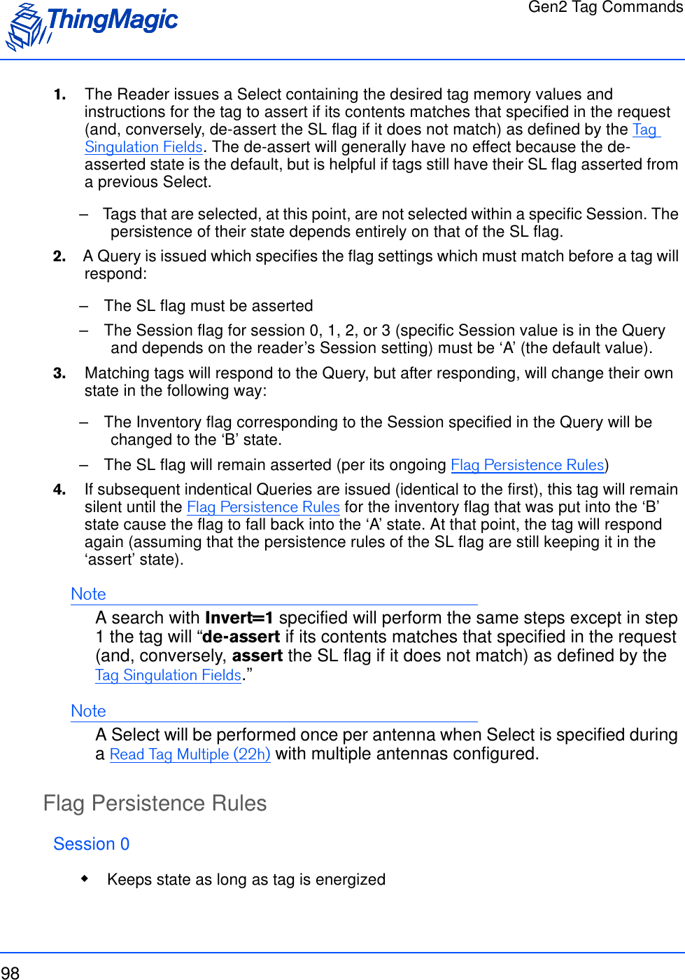
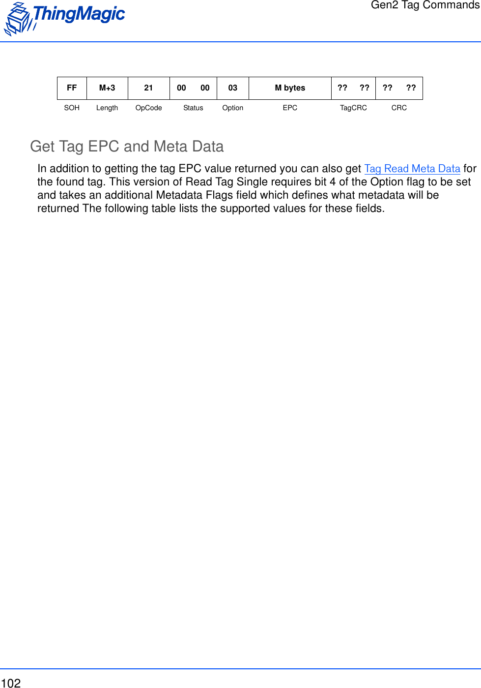
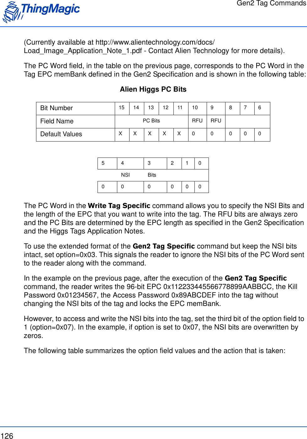
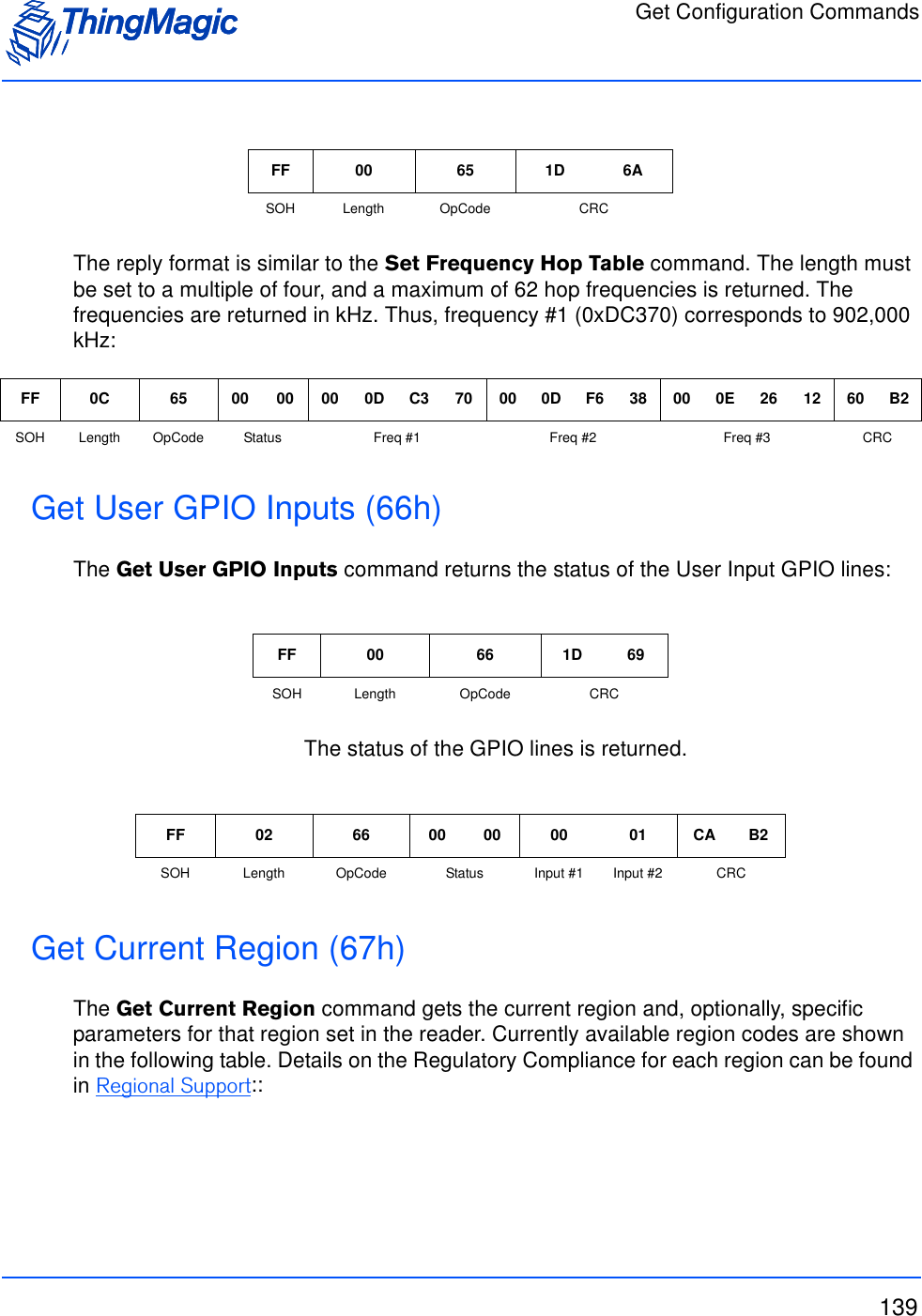
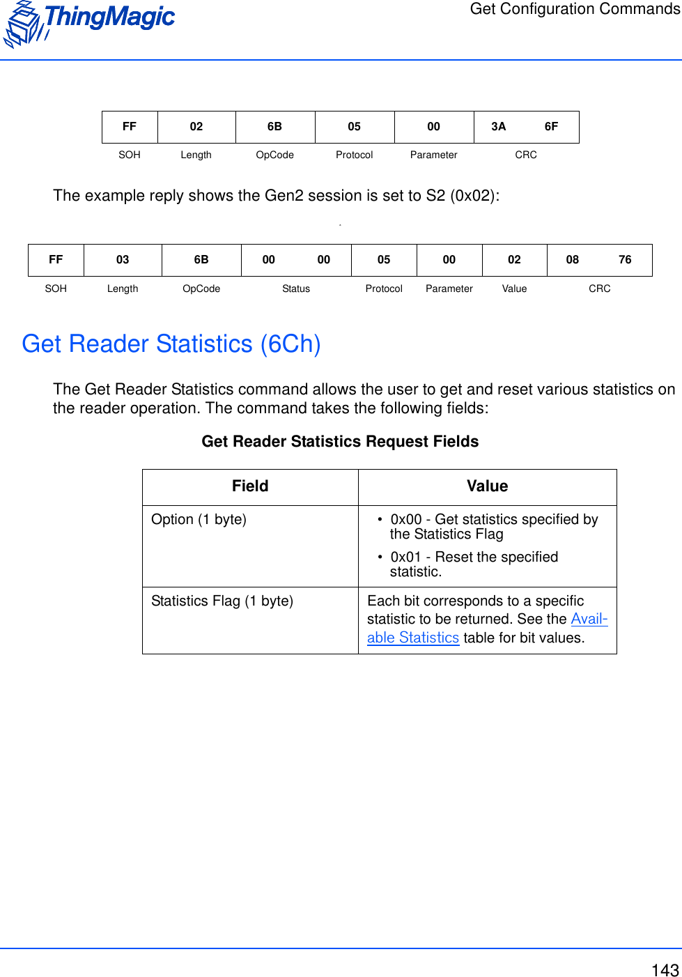
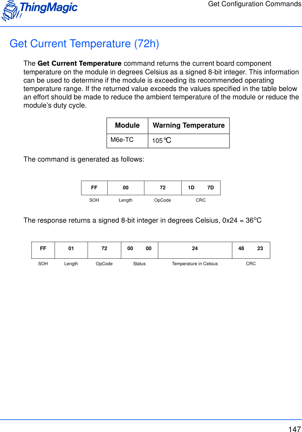
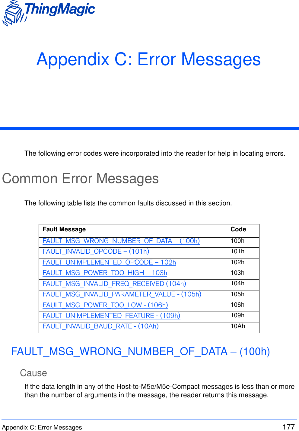
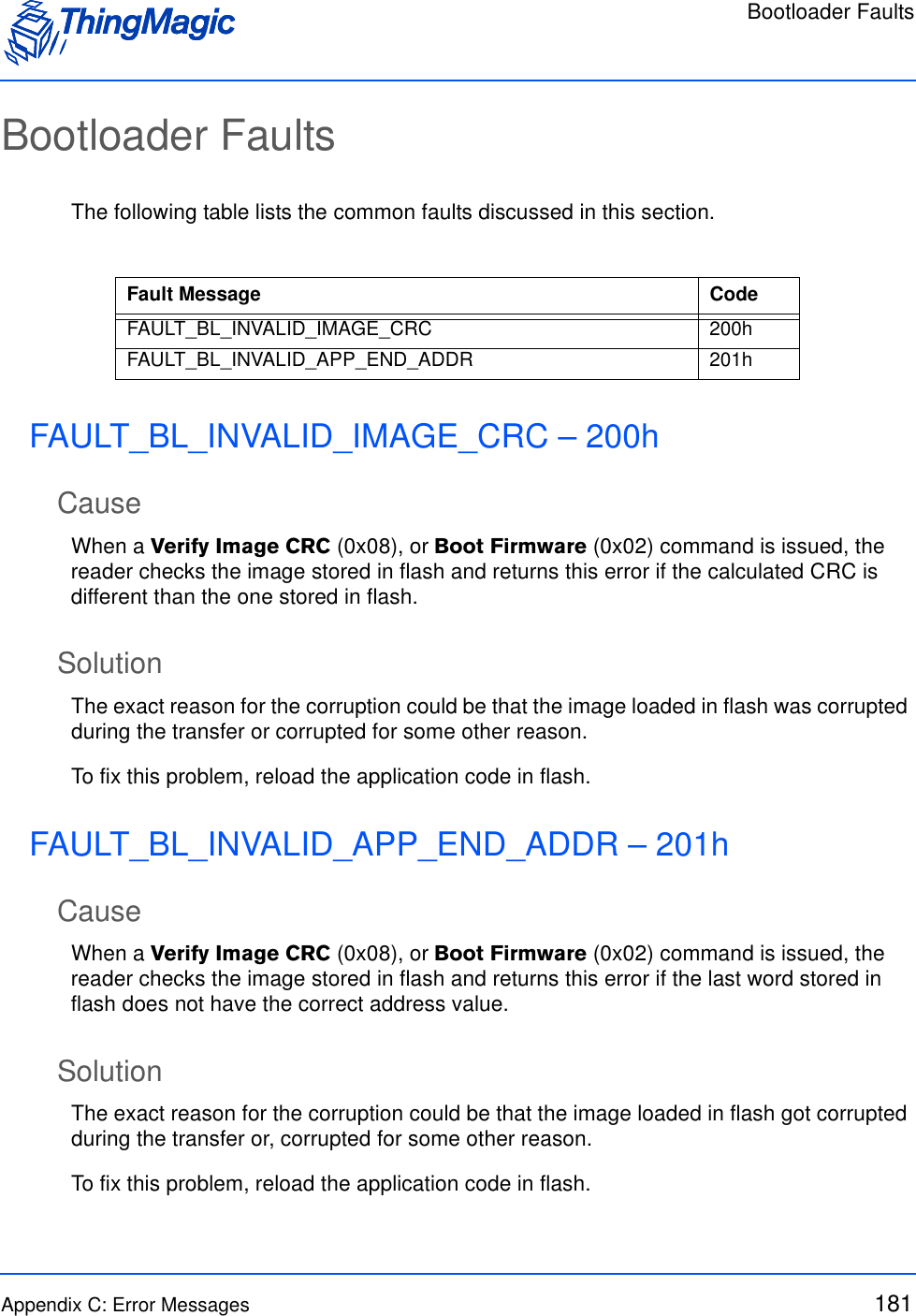
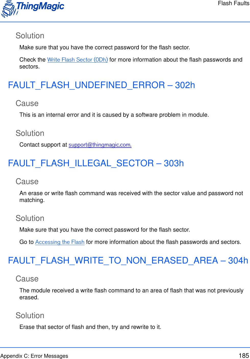
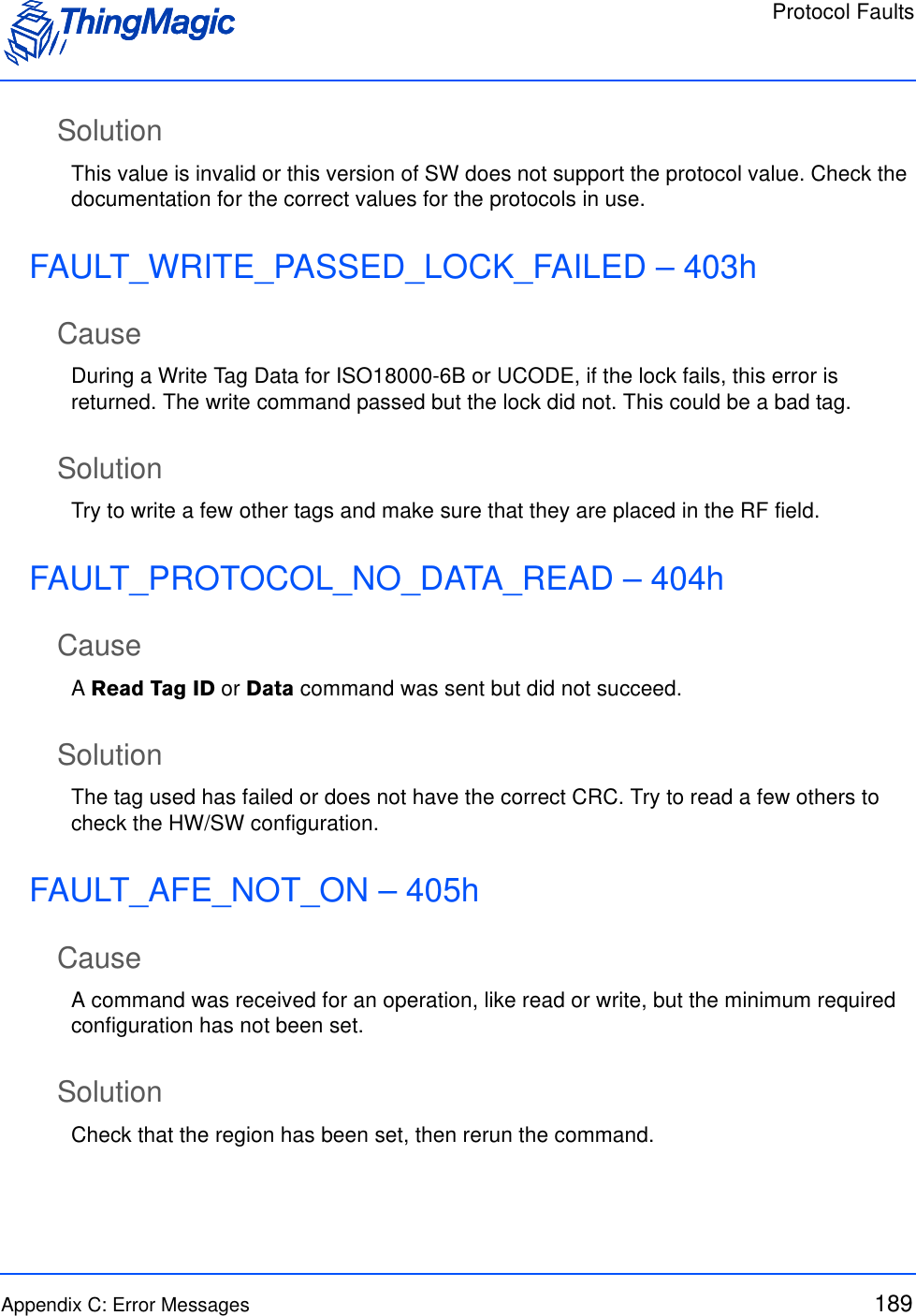
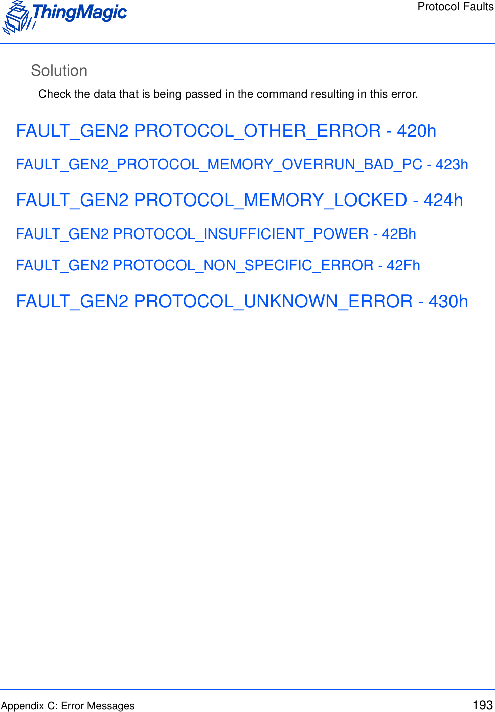
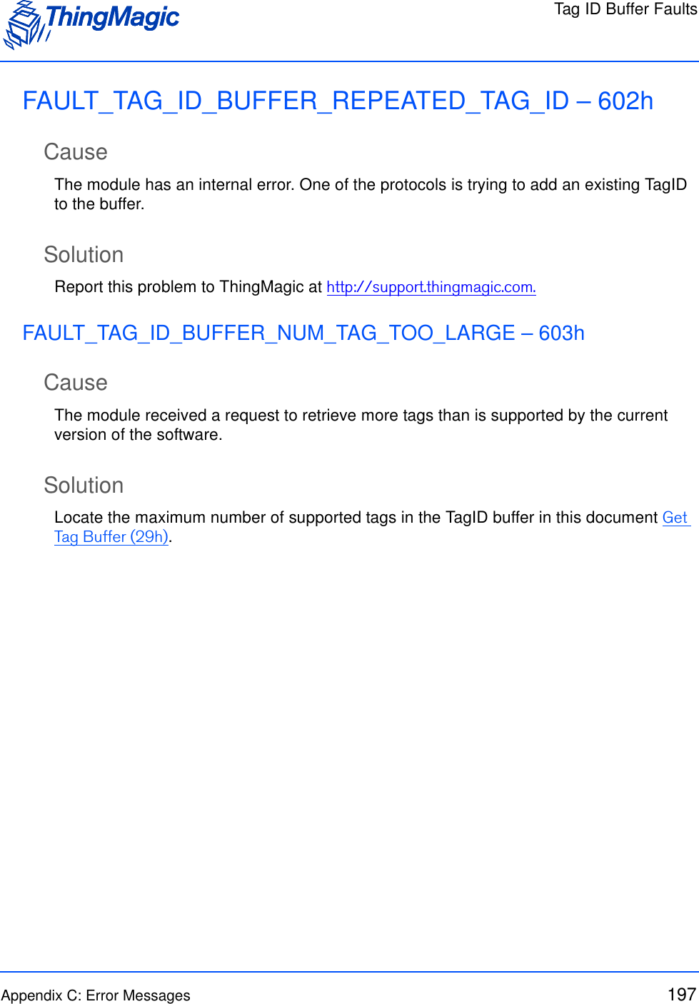
![Multi-Protocol Tag Commands54Clear Tag Buffer (2Ah)The Clear Tag Buffer command resets the tag buffer. This clears the buffer of any current tags and reset the read index to 0. A Multi-Protocol Tag Read or Read Tag Multiple command must be issued to load new tags into the buffer.If Clear Tag Buffer or Get Tag Buffer is not used after a Multi-Protocol Tag Read to remove all tags, old tags will be left in the buffer. This means that if tags that have not been removed from the buffer are read again they will not be added to the buffer as second time, only their Read Count will be incremented.Multi-Protocol Tag Read (2Fh)The Multi-Protocol Tag Read command allows tag reading and inventorying commands to be performed on tags with different protocols at the same time, using a single command. This command contains the following request fields:Multi-Protocol Tag Read Request FieldsFF 00 2A 1D 25SOH Length OpCode CRCField Value DescriptionTM OpCode 0x2F TM OpCode indicating a multi-protocol opera-tion.Timeout [2 bytes] Indicates how long the entire command should spend attempting the operation, in mil-liseconds. When TM Option=0x00 the time gets divided equally across each protocol specified.TM Options • 0x00 = Basic Multi-protocol search. Uses Protocol Bitmask Indicates the operation to perform and addi-tional fields that will be required.Command Opcode • 0x00 - reserved• 0x21 - tag read single• 0x22 - tag read multipleIndicates the command that will be performed for each protocol specified.Note: Allegro/Title-21 is not supported with tag read multiple.Note: Allegro/Title-21 uses Read Request (28h; C003h) for tag read single.](https://usermanual.wiki/TransCore/76007.Users-Manual/User-Guide-1204374-Page-54.png)
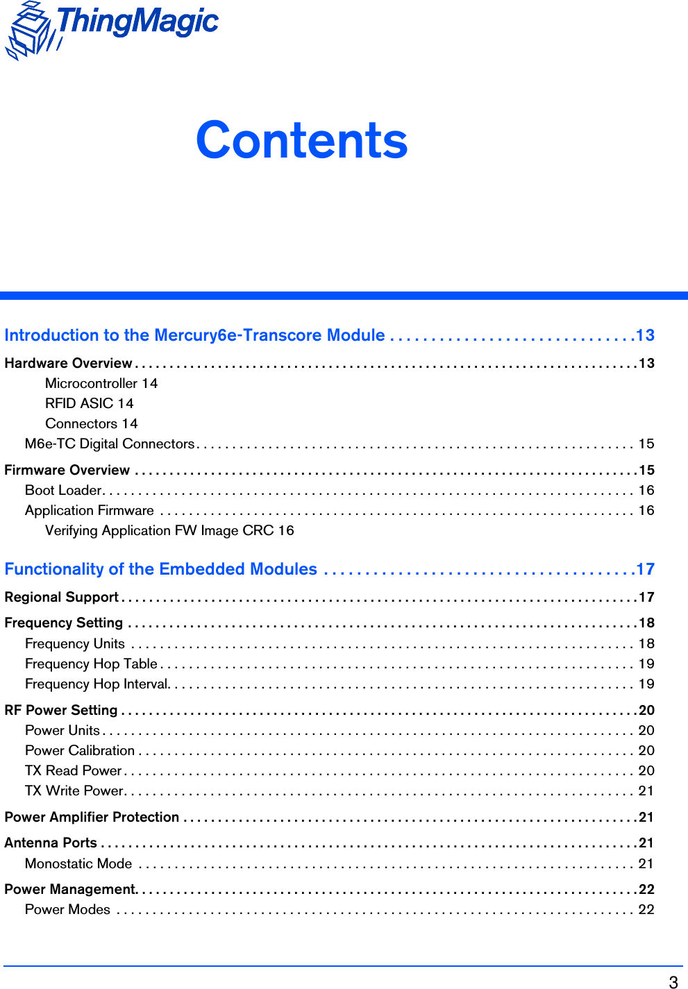
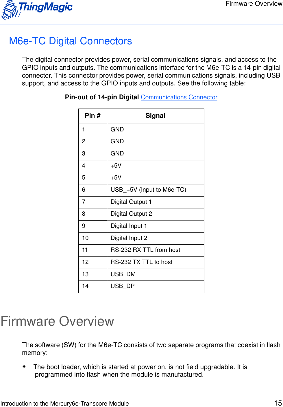
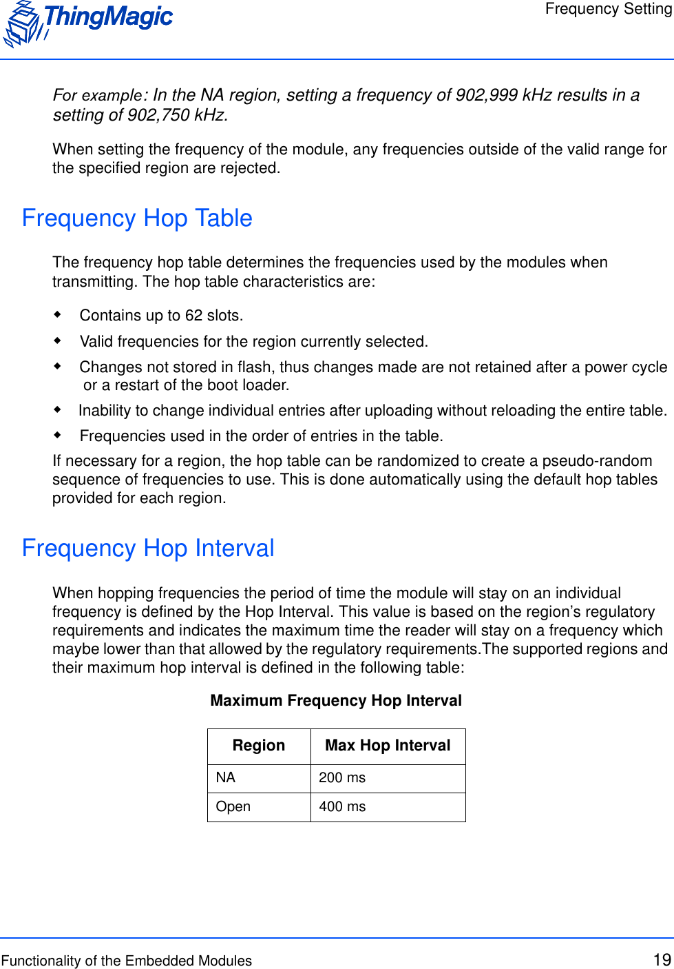
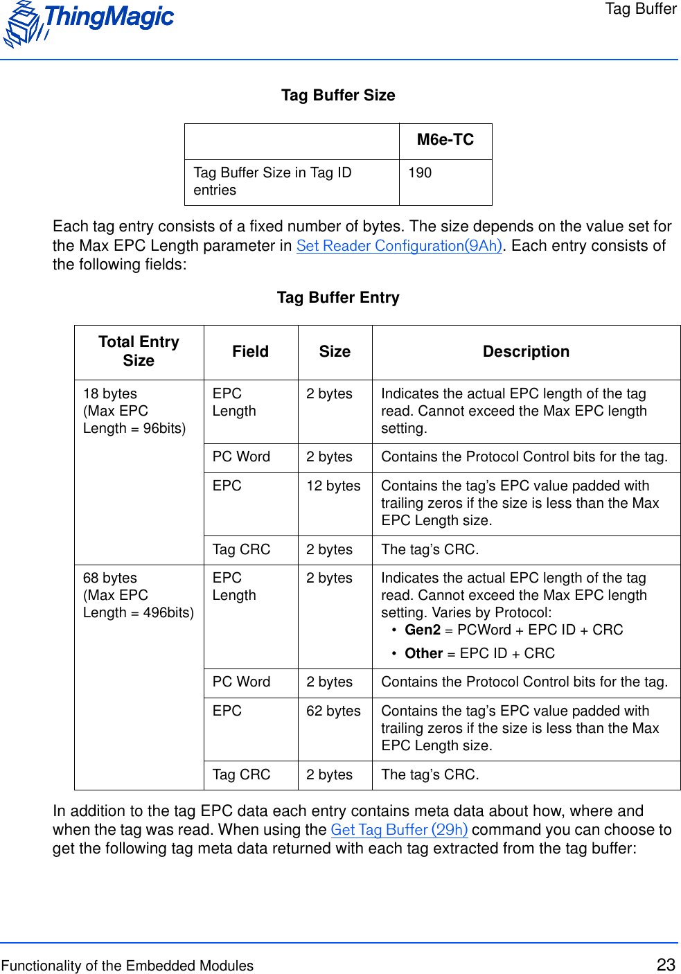
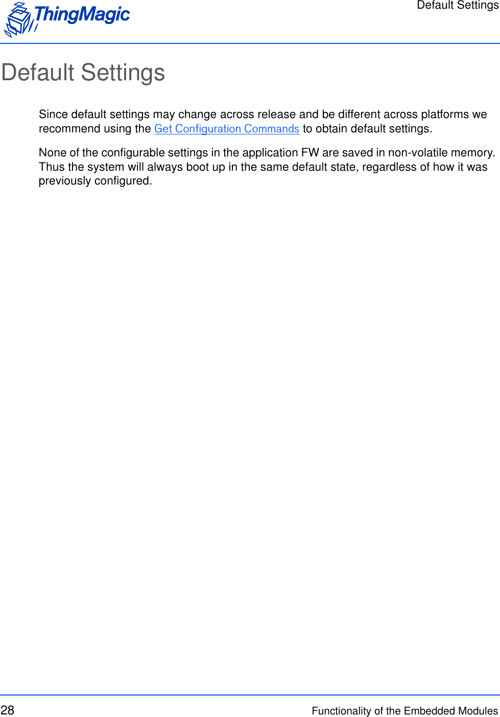
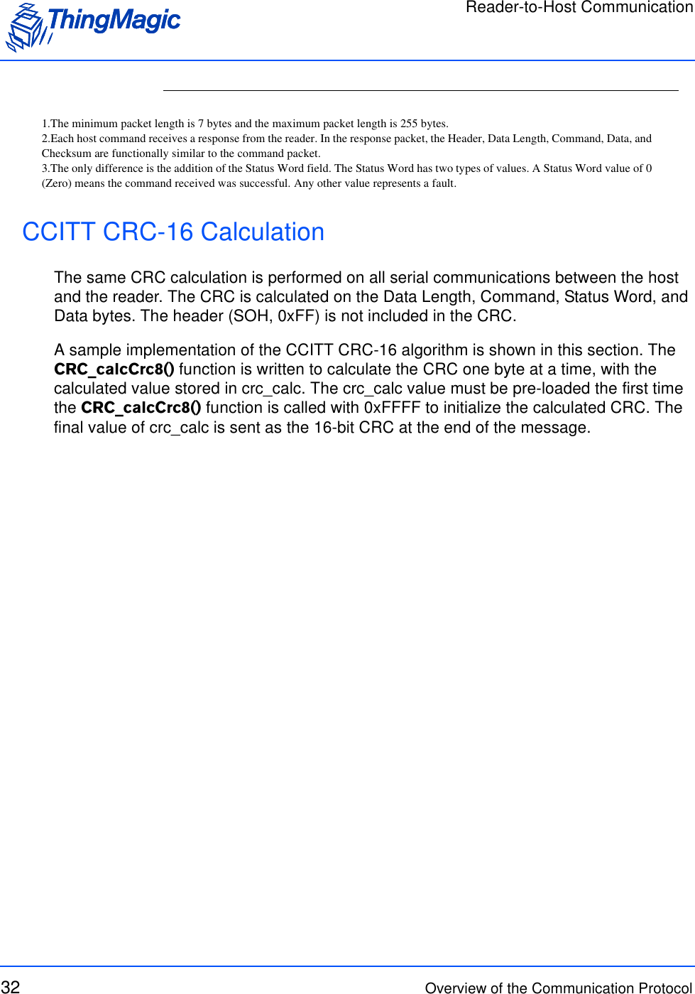
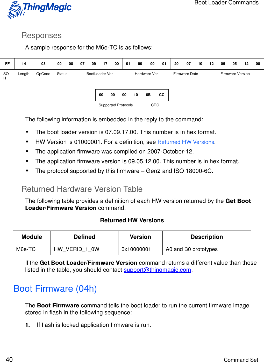
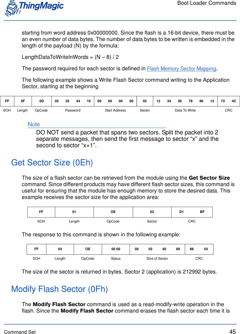
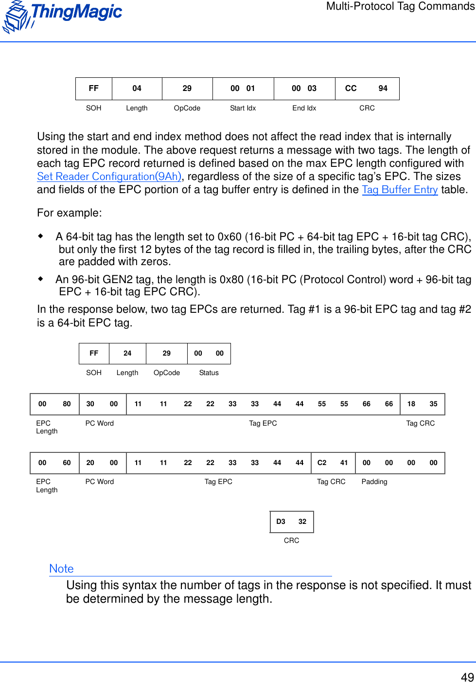
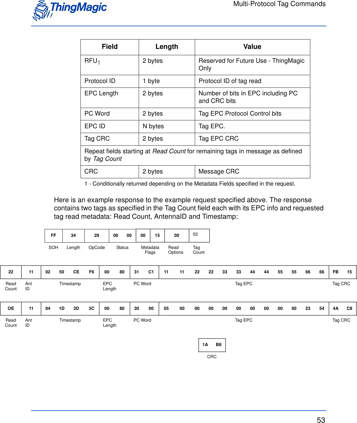
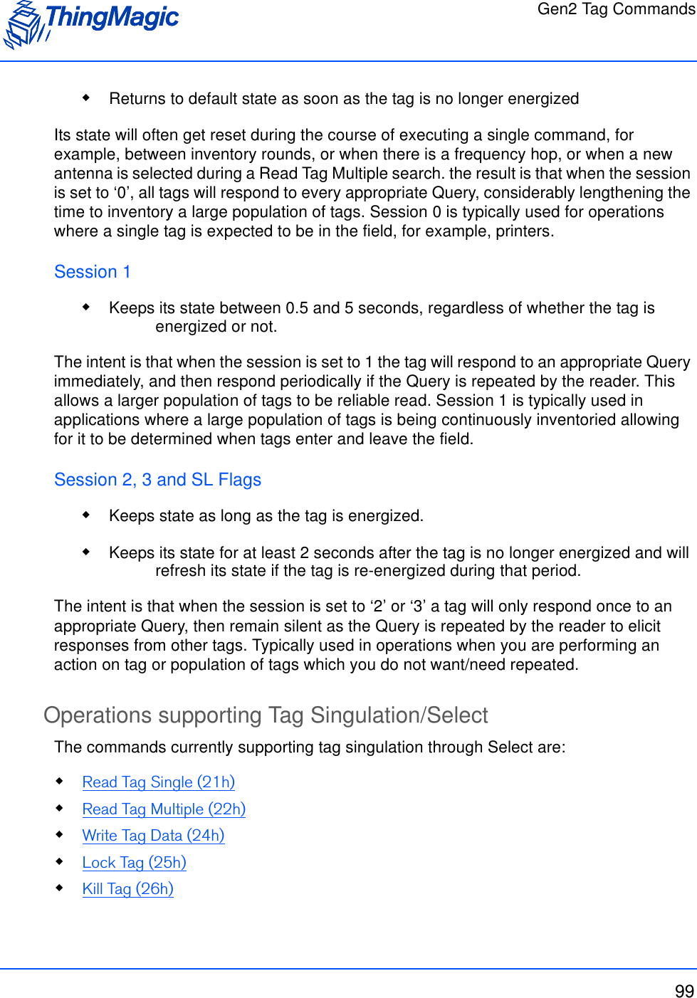
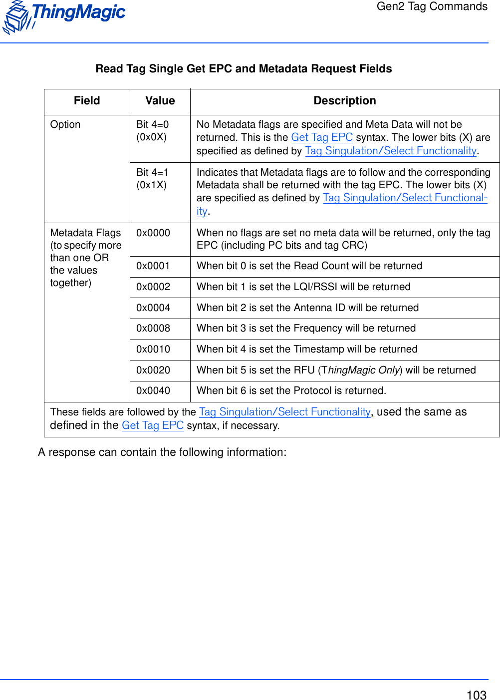
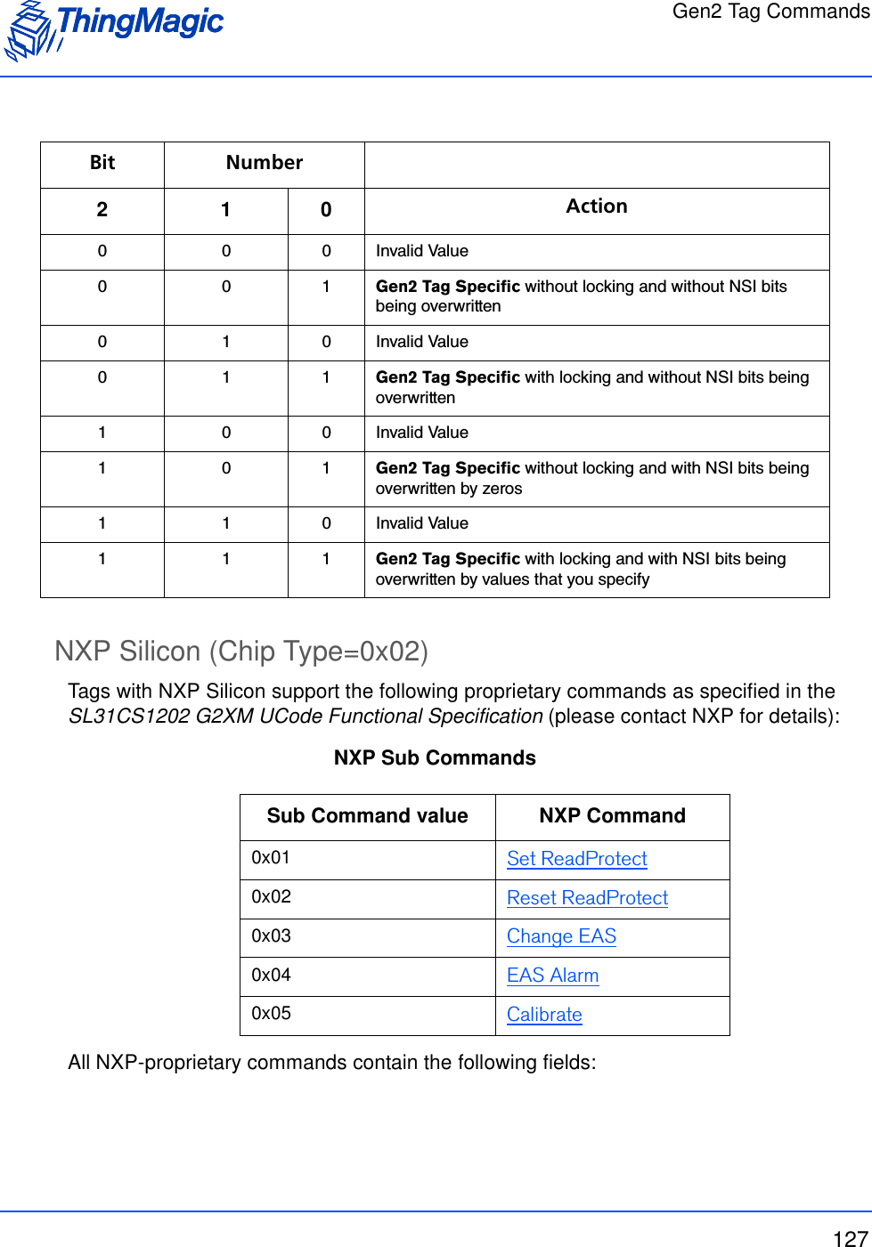
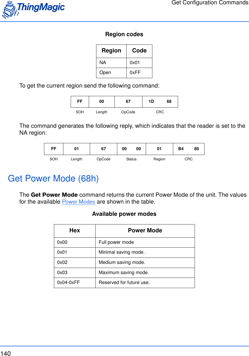
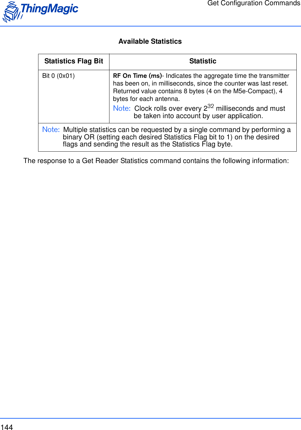
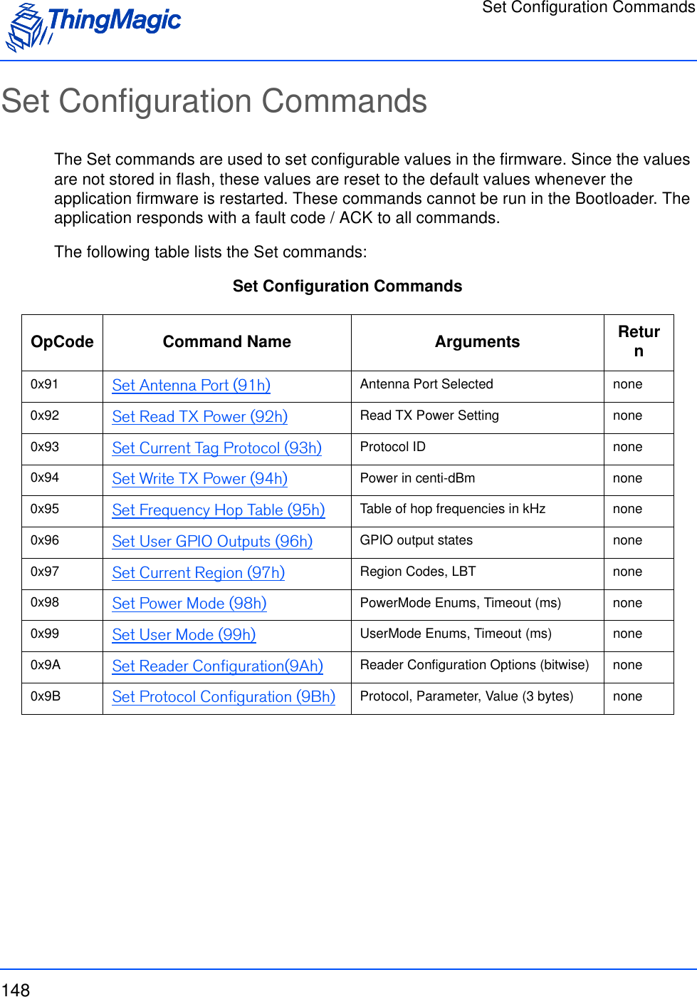
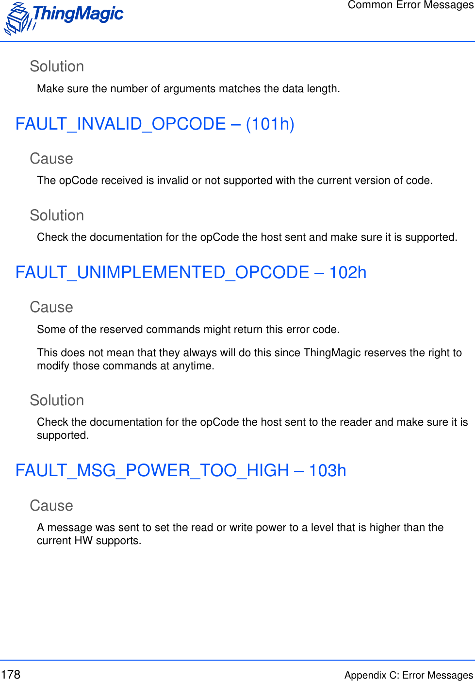
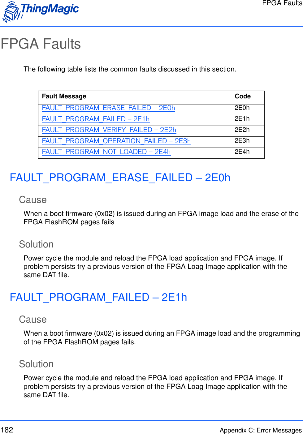
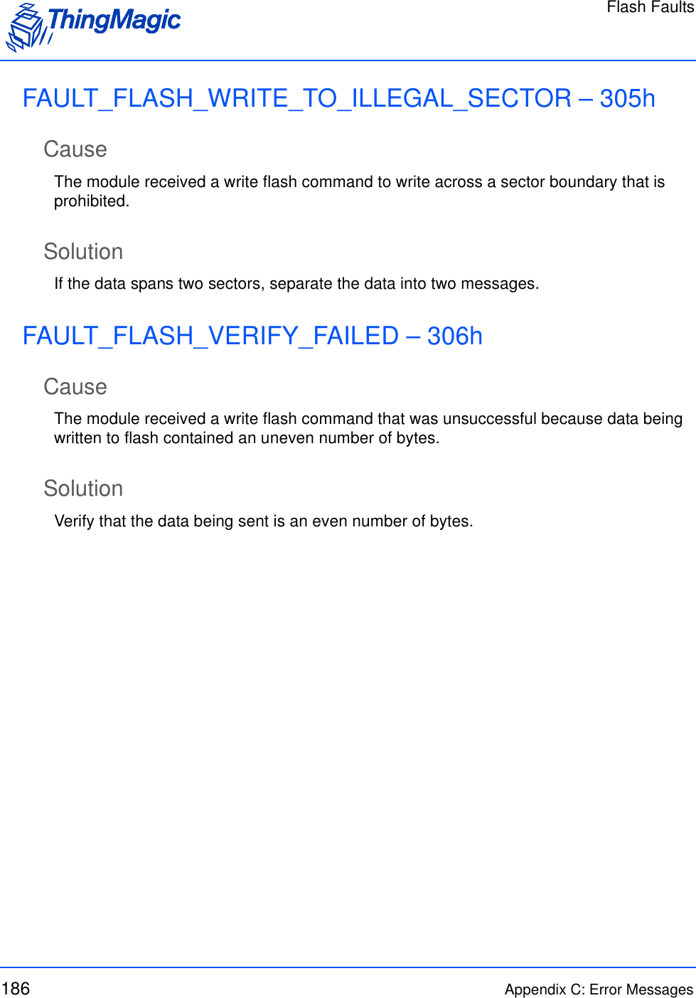
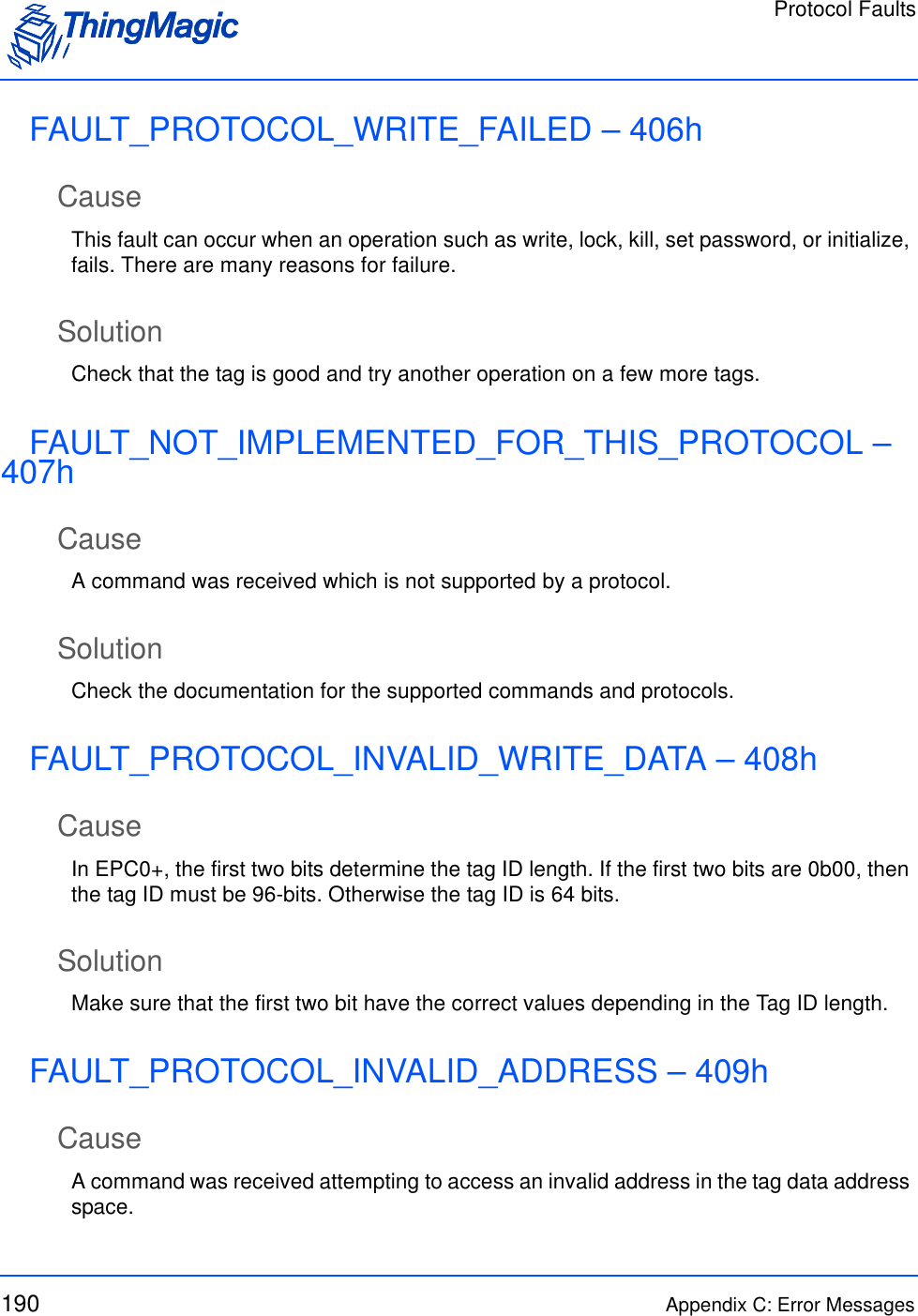
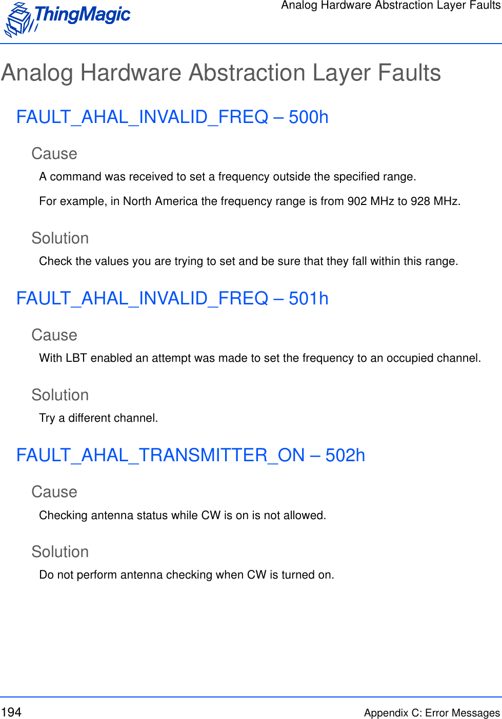
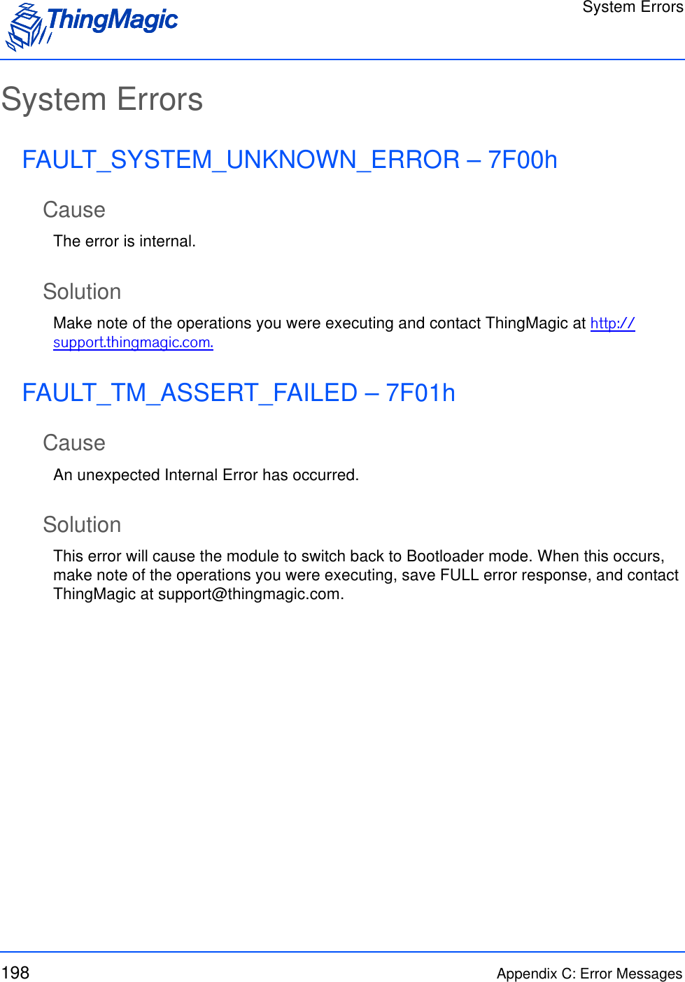
![Multi-Protocol Tag Commands55Search Flags [2 bytes - bitwise setting]Bit 0 = Enable end on tags foundNote: Least Significant Bit = bit 0Indicates search options. When bit is set = 1 the option will be enabled. • Bit 0 = 1 (0x01) the search will stop after the first tag is found, after completing that protocols entire timeout. i.e. if 4 protocols are specified with a 100ms timeout and a tag is found during searching on the second protocol the remaining protocols will not be searched and the command will return after 50ms.Bit 0 = 0 all protocols will be searched, using entire timeout.TM Option = 0x00 Fields - The following field is only used when TM Option = 0x00Protocol Bitmask Enables [4 bytes - bitwise setting]bit 0-3 = not usedbit 4 (0x00000010) = Gen2bit 5-25 = not usedbit 26 (0x04000000) = eGobit 27 (0x08000000) = SeGobit 28 (0x10000000) = ATAbit 29 (0x20000000) = Allegro/Title-21Note: Least Significant Bit = bit 0Indicates the protocols to operate on. If the protocols bit is set to ‘1’ tags of that protocol will be included in the operation.OR values together for final settingField Value Description](https://usermanual.wiki/TransCore/76007.Users-Manual/User-Guide-1204374-Page-55.png)
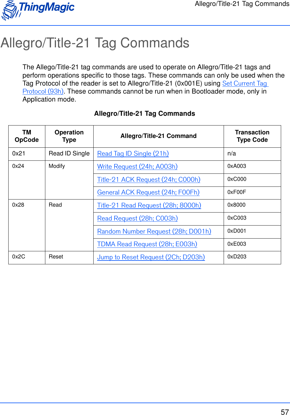
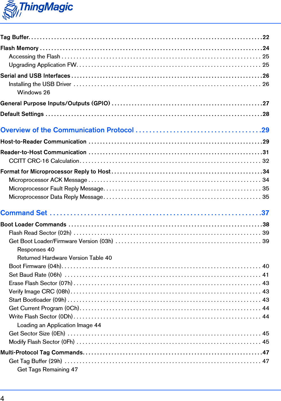
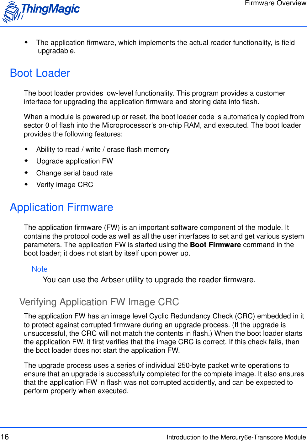
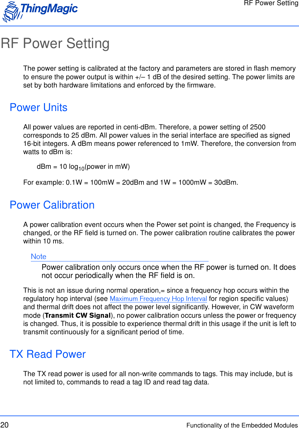
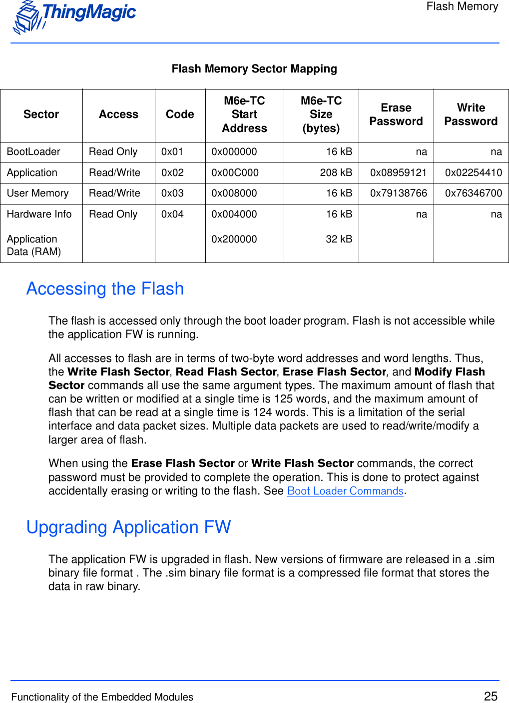
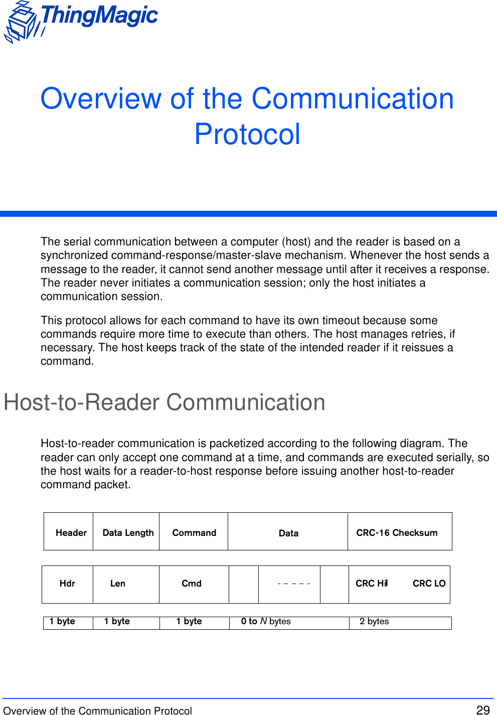
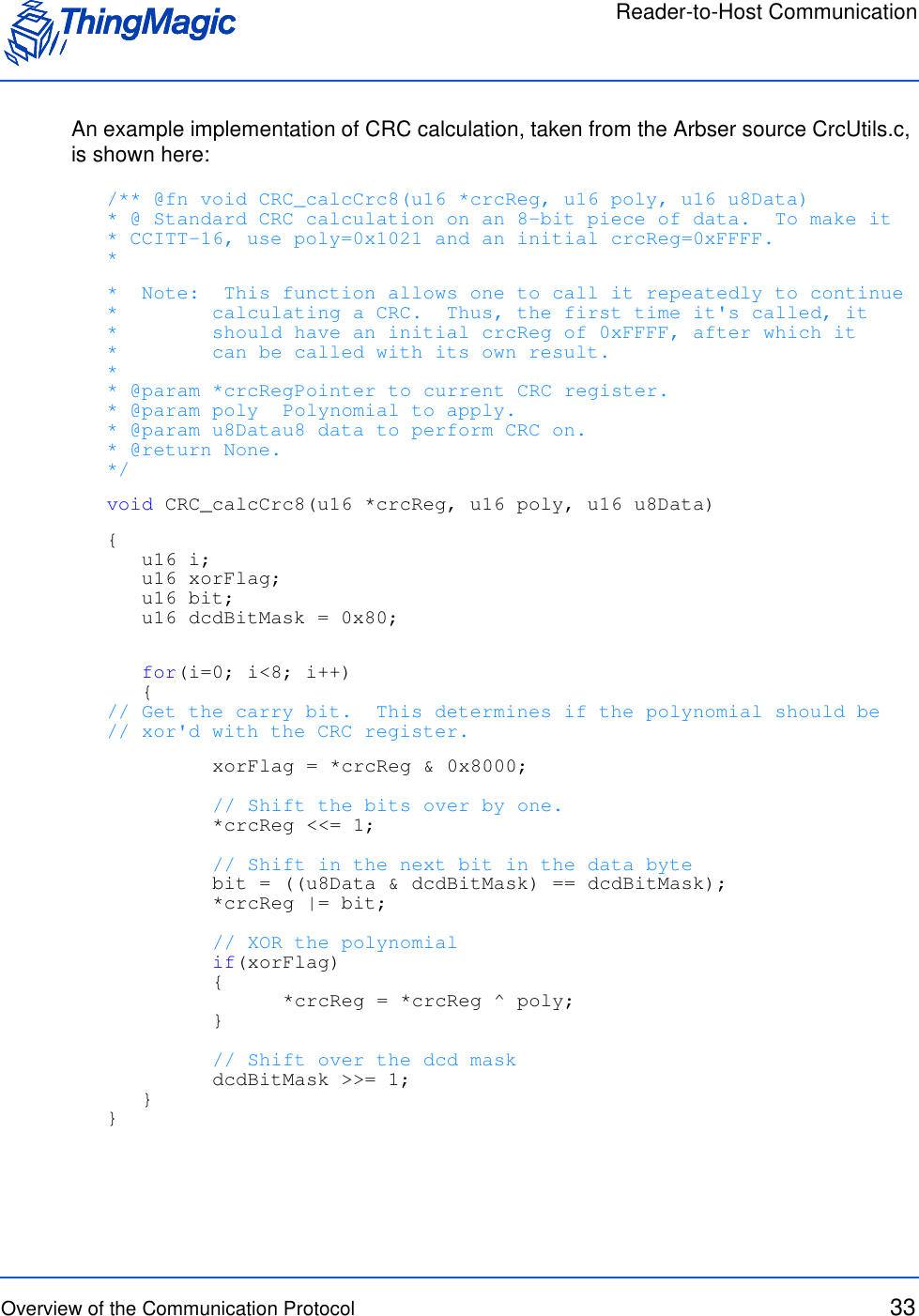
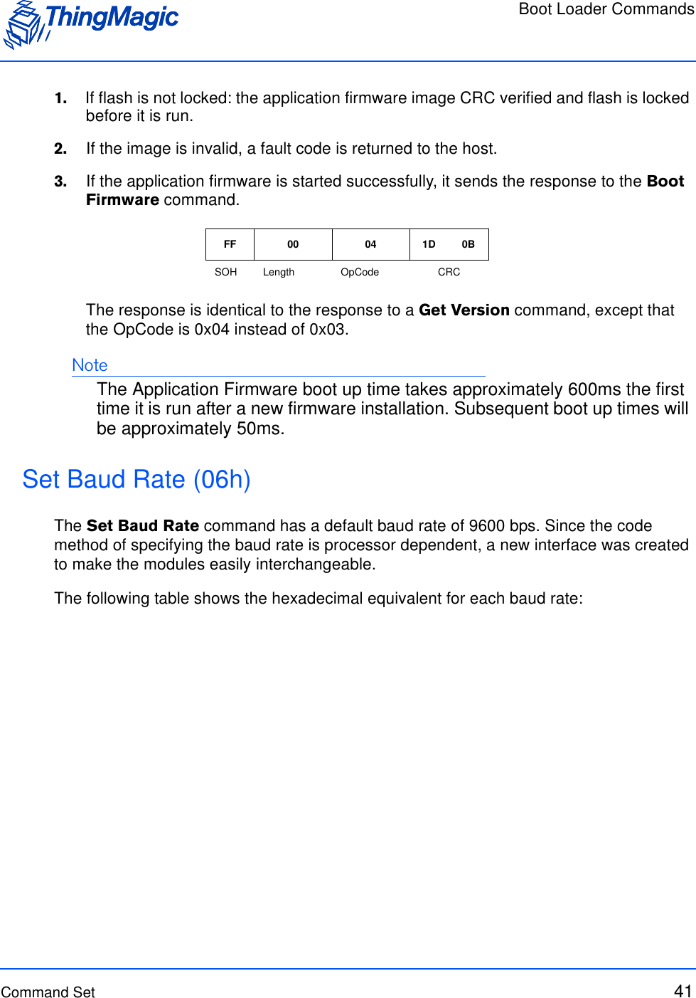
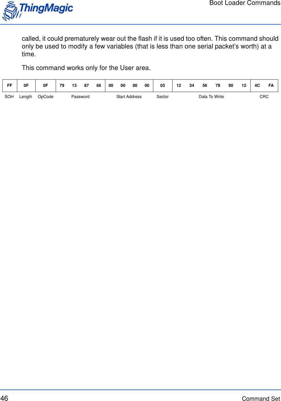
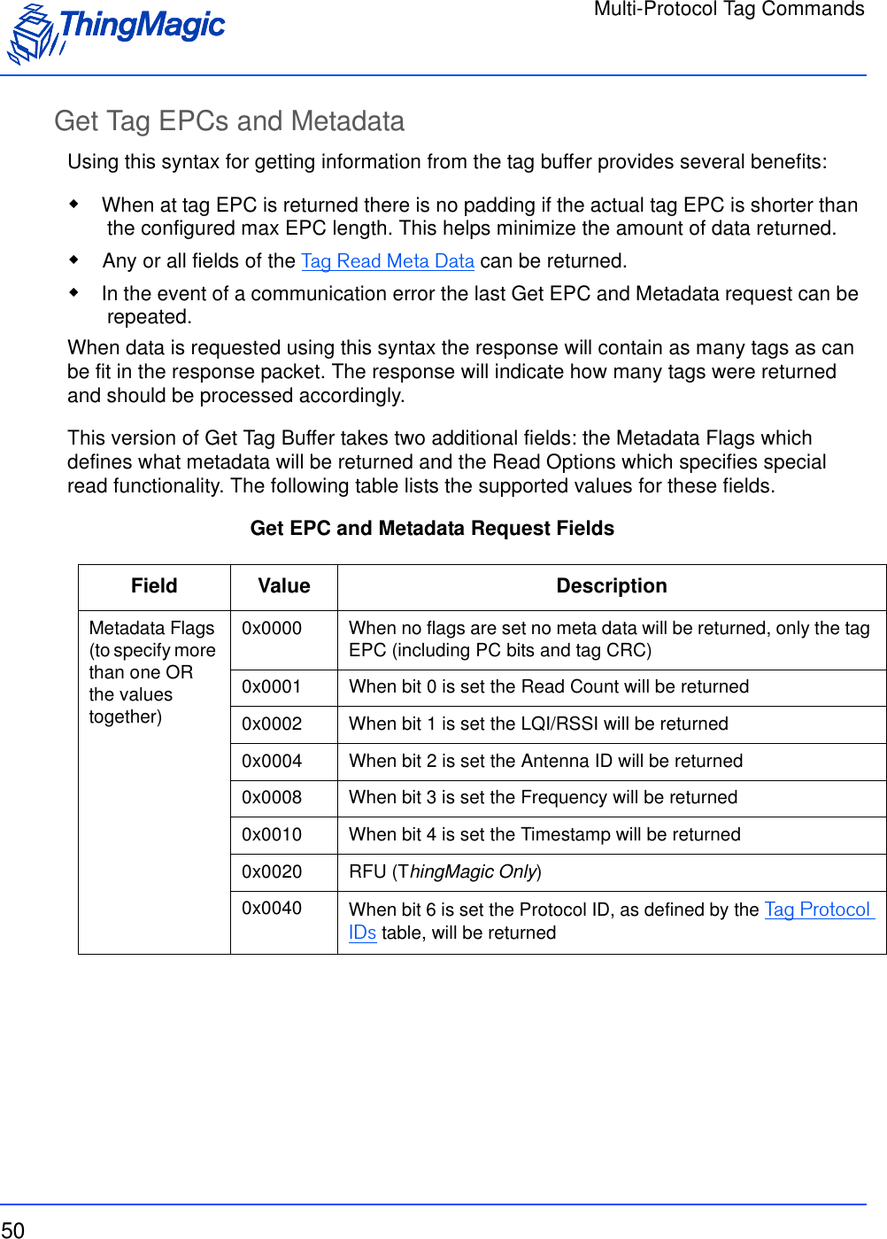
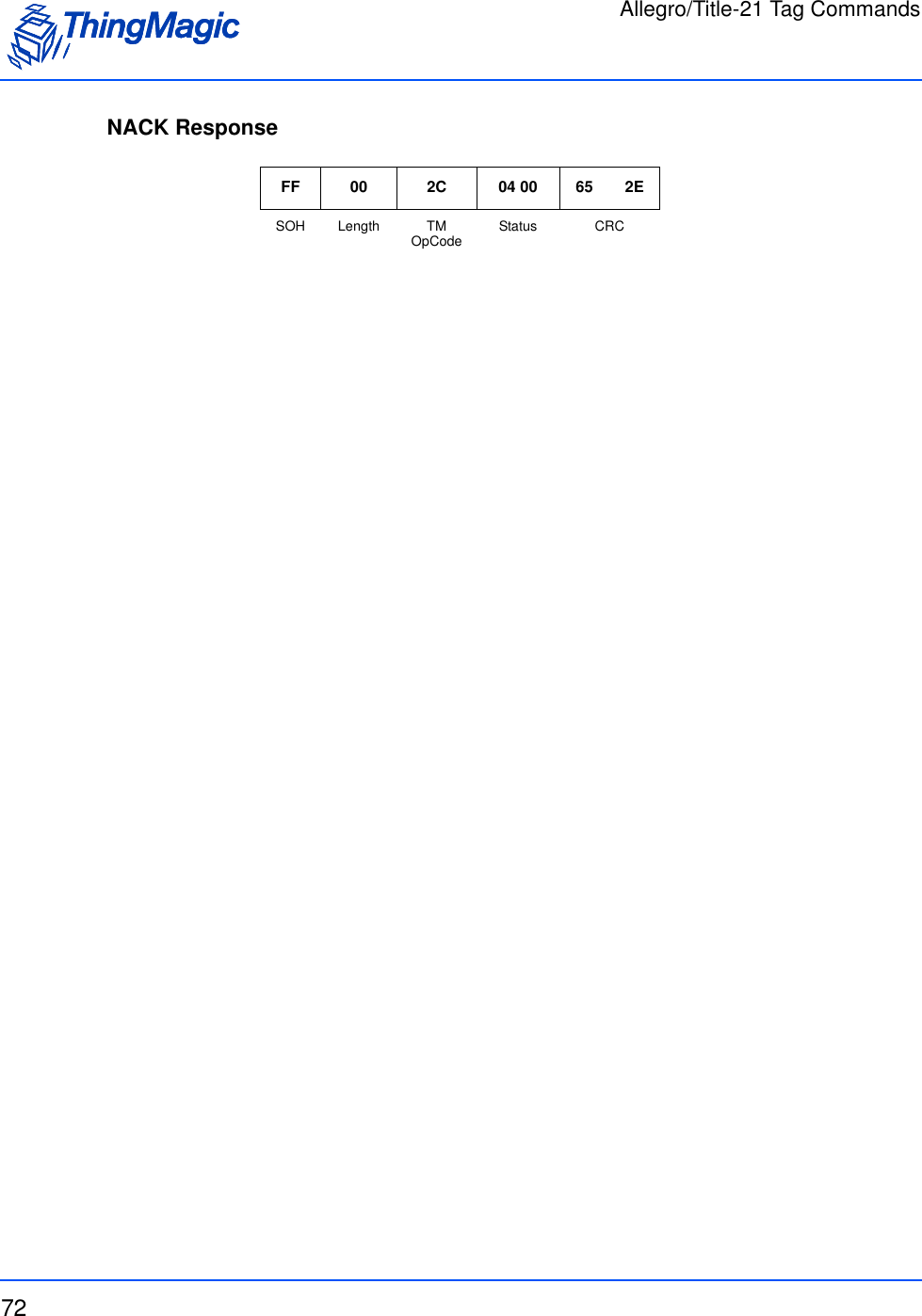
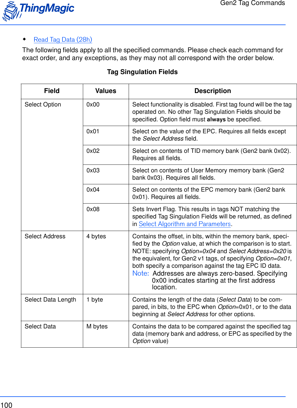
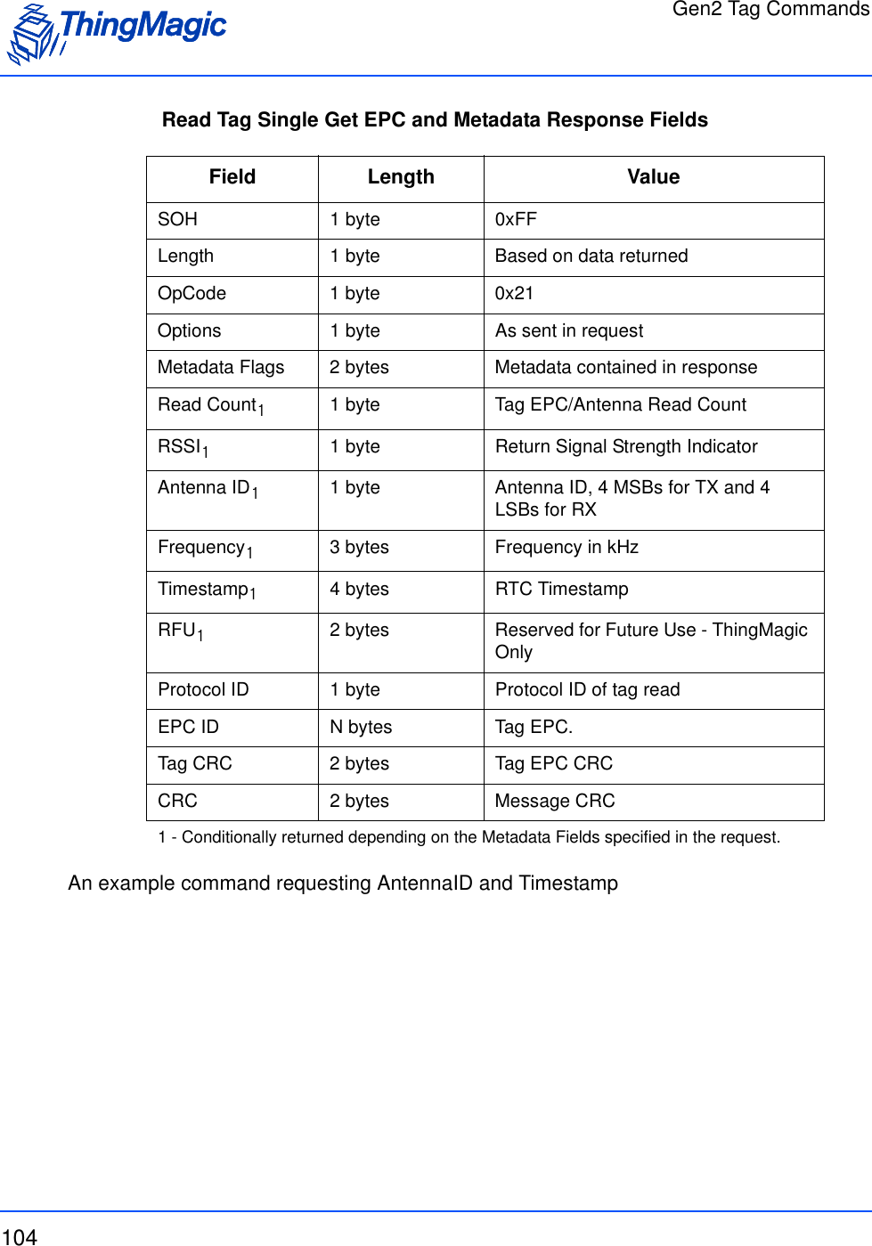
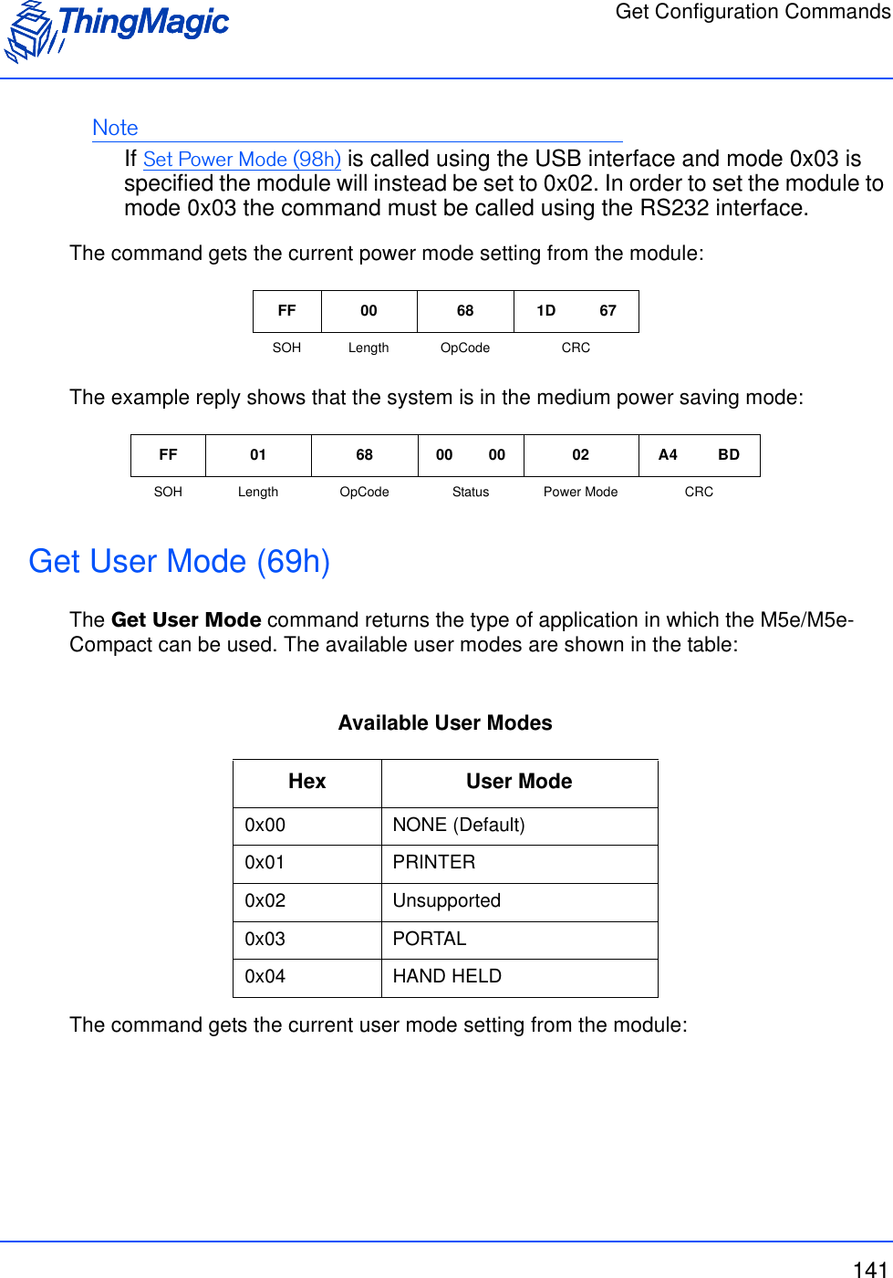
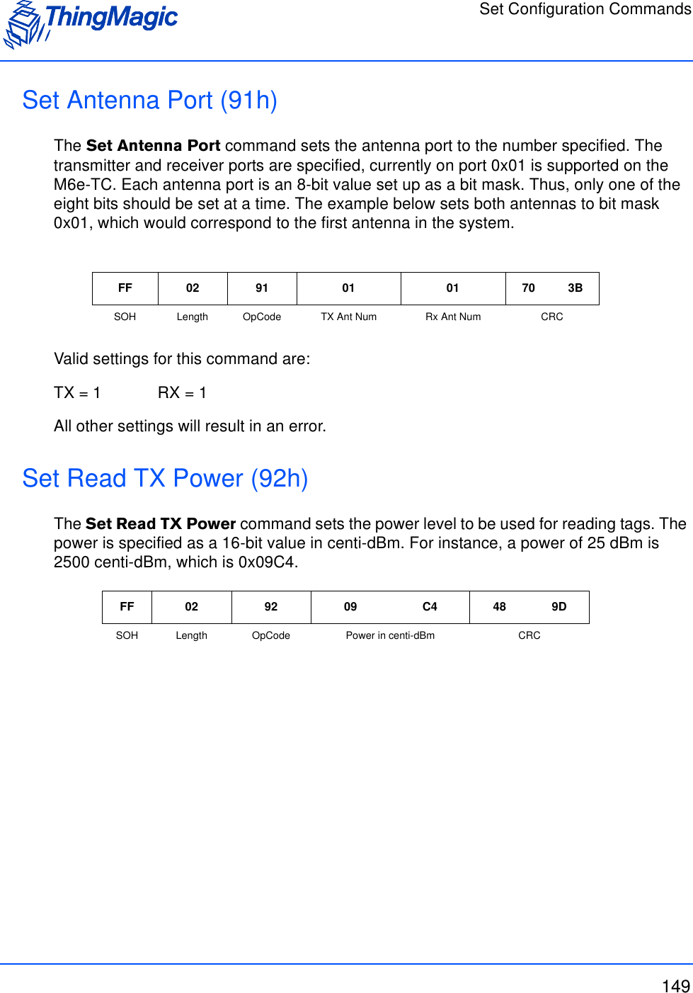
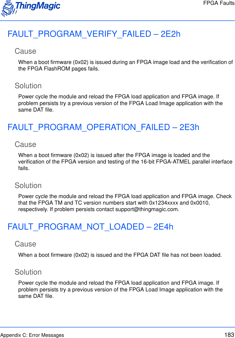
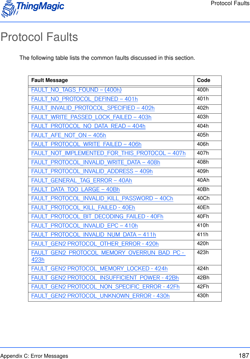
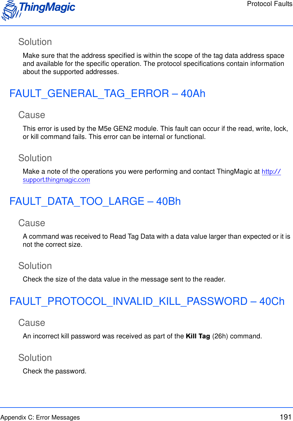
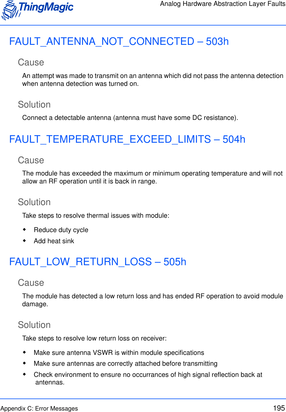
![Allegro/Title-21 Tag Commands58Command SyntaxAll Allegro/Title-21 tag commands, except Read Tag ID Single, follow the same standard syntax. The commands are grouped into three ThingMagic M6e-TC OpCodes, as defined in the Allegro/Title-21 Tag Commands table, indicating their general operation type. In addition to the 1 of 3 OpCodes each command will have the following fields:Standard Request FieldsThe remaining fields for each command are as defined by Transcore based on the Transaction Type Code. They occur in the same order and require the same values as described in the [Transcore doc reference].Field Value DescriptionTM OpCode 0x24 TM OpCodeTimeout [2 bytes] Indicates how long the command should spend attempting the operation, in milliseconds.TM Options 0x00 Reserved for Future Use. Transaction Type Code [2 bytes] Allegro/Title-21 code indicating operation to per-form.](https://usermanual.wiki/TransCore/76007.Users-Manual/User-Guide-1204374-Page-58.png)
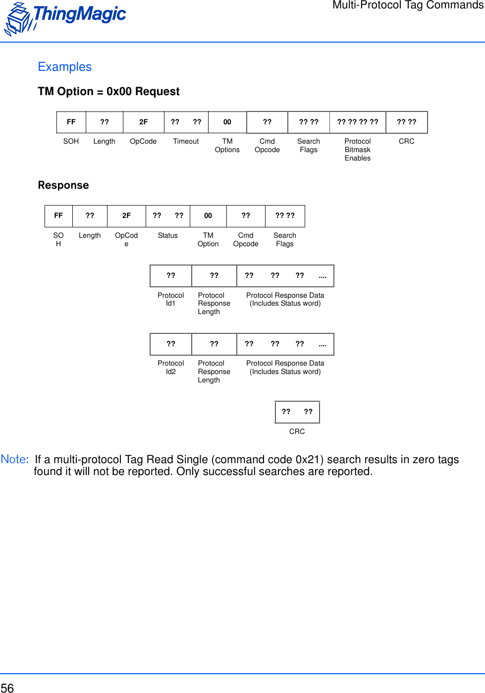
![Allegro/Title-21 Tag Commands59Read Tag ID Single (21h)The Read Tag ID Single/Tag Detect command performs a search operation and returns the first Allegro/Title-21 tag it finds. Read Tag ID Single Request FieldsExamplesAn example, without TM Options, command:Field Value DescriptionTM OpCode 0x21 TM OpCodeTimeout [2 bytes] Indicates how long the command should spend attempting the operation, in milliseconds.TM OptionsNote: This and following fields are optional.Bit 4(LSB=bit 0))• 0 - Metadata flags must not be passed and Meta Data will not be returned. • 1 - Metadata flags must be passed and the corresponding Metadata shall be returned with the tag EPC. Metadata Flags (to specify more than one OR the val-ues together)0x0000 When no flags are set no meta data will be returned, only the tag EPC.0x0001 When bit 0 is set the Read Count will be returned0x0002 When bit 1 is set the LQI/RSSI will be returned0x0004 When bit 2 is set the Antenna ID will be returned0x0008 When bit 3 is set the Frequency will be returned0x0010 When bit 4 is set the Timestamp will be returned0x0020 When bit 5 is set the RFU (ThingMagic Only) will be returned0x0040 When bit 6 is set the Protocol is returned.FF 02 21 00 FA D6 1BSOH Length OpCode Time-out (ms) CRC](https://usermanual.wiki/TransCore/76007.Users-Manual/User-Guide-1204374-Page-59.png)
![Allegro/Title-21 Tag Commands61Write Request (24h; A003h)The Write Request command writes data to the specified area of the specified tag. A non-acknowledge (NACK) error response shall be returned if an invalid password was included in the request. This command contains the following request fields:Write Request FieldsExamplesAn example command requesting ? be written to tag ? with a User Password = 0x? is:Field Value DescriptionTM OpCode 0x24 TM OpCode for tag modification operationsTimeout [2 bytes] Indicates how long the command should spend attempting the operation, in milliseconds.TM Options 0x00 Reserved for Future Use. Transaction Type Code 0xA003 Allegro/Title-21 code indicating operation to per-form.Options [1 byte] Command specific optionsPage Number [2 bytes] Indicates which page of the tag is to be written to.Tag ID [4 bytes] Optional, based on value of Options parameter. Indicates the ID of the tag to operate on.User Password/ Global Password [4/8 bytes] Optional, based on the value of the Options param-eter. The password to operation on the tag, if required.Page Data Byte Count [1 byte] Indicates the number of data bytes to follow.Page Data Bytes [N bytes] Data to write to the tag.FF 0E + N24 ?? ?? 00 A0 03 ?? ?? ??SOH Length TM OpCode Timeout (ms) TM Option Transaction Type Code Option Page Number?? ?? ?? ?? ?? ?? ?? ?? ?? NN NN ?? ??Tag ID User/Global Password Page Data CountPage Data CRC](https://usermanual.wiki/TransCore/76007.Users-Manual/User-Guide-1204374-Page-61.png)
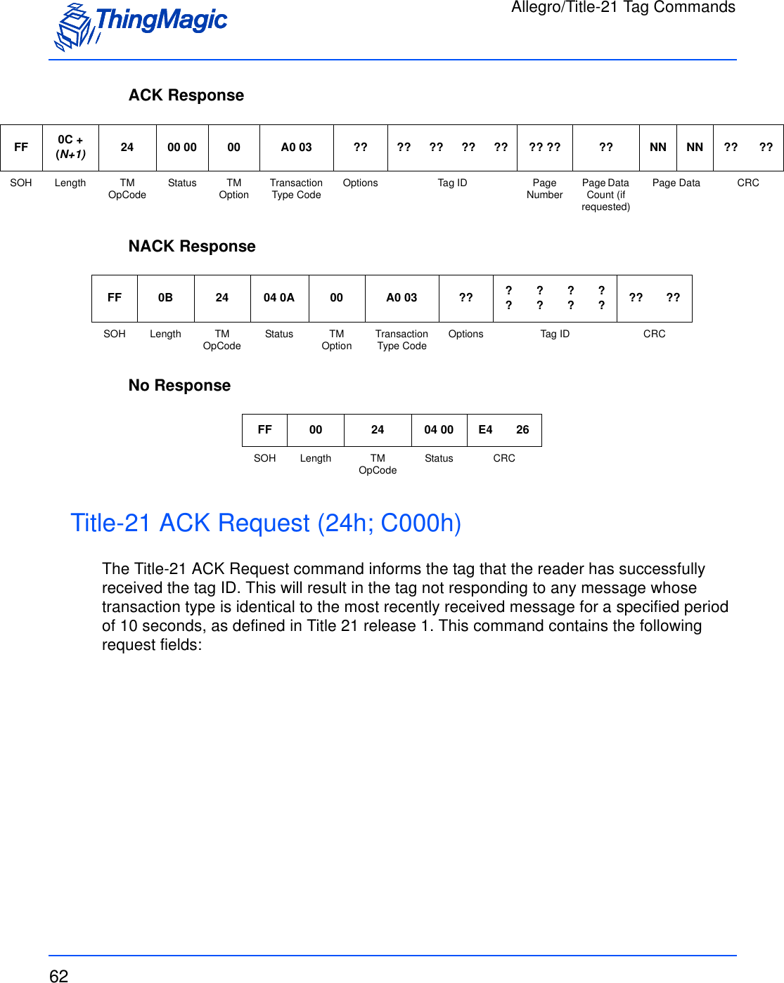
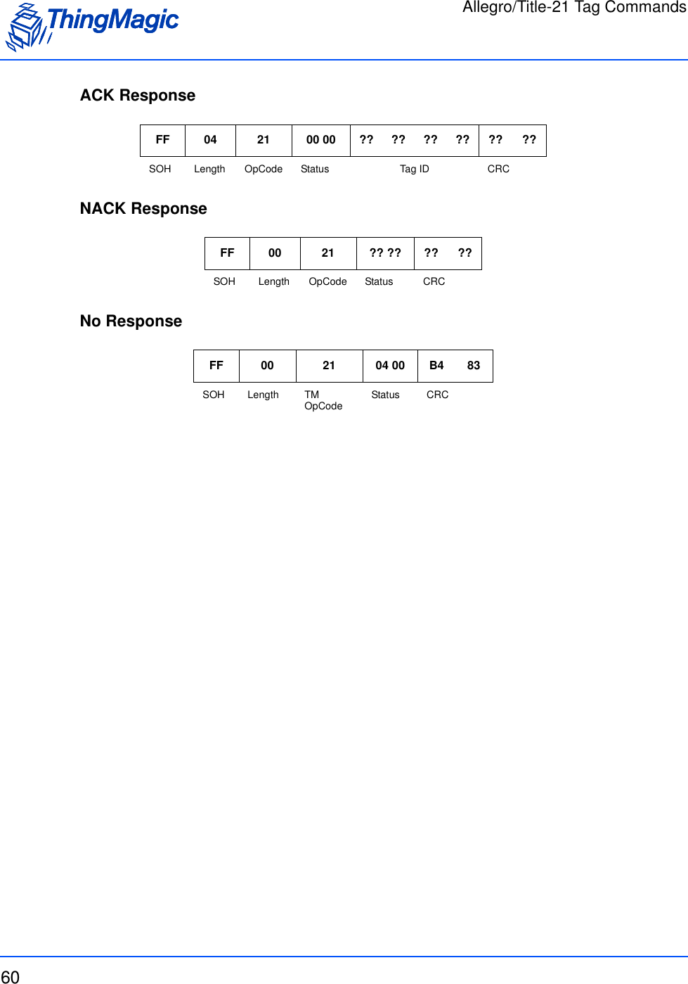
![Allegro/Title-21 Tag Commands63Title-21 ACK Request FieldsExamplesAn example command requesting an ACK from tag XXX from reader XXX is:ACK ResponseNACK ResponseField Value DescriptionTM OpCode 0x24 TM OpCode for tag modification operationsTimeout [2 bytes] Indicates how long the command should spend attempting the operation, in milliseconds.TM Options 0x00 Reserved for Future Use. Transaction Type Code 0xC000 Allegro/Title-21 code indicating operation to per-form.Tag ID [4 bytes] Indicates the ID of the tag to operate on.Reader ID [4 bytes] The reader number for the reader that is acknowl-edging the receipt of the message.Transaction Status Code [2 bytes] Code indicating the status of the transaction. FF 0D 24 ?? ?? 00 C0 00 ?? ?? ?? ?? ?? ?? ?? ?? ?? ?? ?? ??SOH Length OpCode Time-out (ms) TM Option Transaction Type Code Tag ID Reader ID Transaction Status Code CRCFF 03 24 ?? ?? 00 C0 00 ?? ??SOH Length TM OpCode Status TM Option Transaction Type Code CRCFF 0B 24 ?? ?? 00 C0 00 ?? ?? ?? ?? ?? ?? ??SOH Length TM OpCode Status TM Option Transaction Type Code Options Tag ID CRC](https://usermanual.wiki/TransCore/76007.Users-Manual/User-Guide-1204374-Page-63.png)
![Allegro/Title-21 Tag Commands64No ResponseGeneral ACK Request (24h; F00Fh)The General ACK Request, or Sign Off Request, command informs the tag that it should not respond to any commands from the reader for the specified time period. This command contains the following request fields:General ACK Request FieldsFF 00 24 04 00 E4 26SOH Length TM OpCode Status CRCField Value DescriptionTM OpCode 0x24 TM OpCode for tag modification operationsTimeout [2 bytes] Indicates how long the command should spend attempting the operation, in milliseconds.TM Options 0x00 Reserved for Future Use. Transaction Type Code 0xF00F Allegro/Title-21 code indicating operation to per-form.Options [1 byte] Command specific optionsTag ID [4 bytes] Indicates the ID of the tag to operate on.Time Out [1 byte] Indicates the amount of time the tag shall ignore commands from the reader, in seconds from 0-127.Condition Code Bits [1 byte] Represents a condition applicable to a tolling envi-ronment.LCD Message Page Pointer [1 byte] Tag memory page where the LCD message to be displayed is stored in ASCII. Valid range = 0x02 - 0x0F.](https://usermanual.wiki/TransCore/76007.Users-Manual/User-Guide-1204374-Page-64.png)
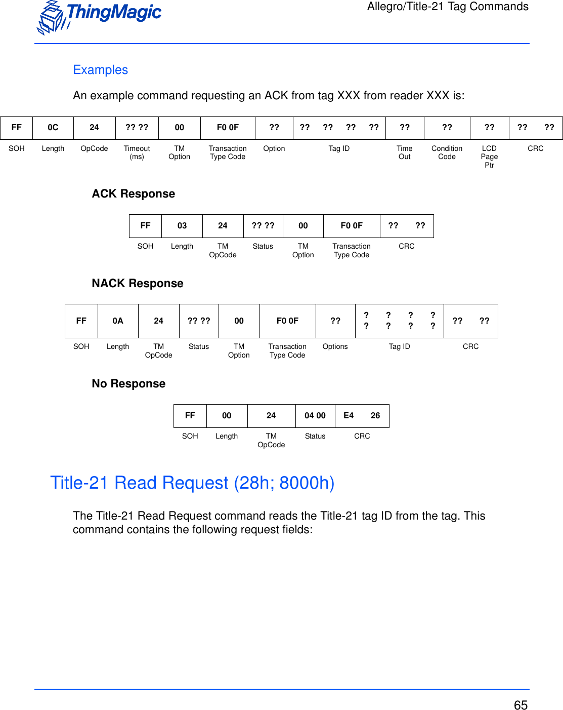
![Allegro/Title-21 Tag Commands66Title-21 Read Request FieldsExamplesAn example command requesting an ACK from tag XXX from reader XXX is:ACK ResponseNACK ResponseNo ResponseField Value DescriptionTM OpCode 0x28 TM OpCode for Read operationsTimeout [2 bytes] Indicates how long the command should spend attempting the operation, in milliseconds.TM Options 0x00 Reserved for Future Use. Transaction Type Code 0x8000 Allegro/Title-21 code indicating operation to per-form.Agency Code [2 byte] Agency operating the reader installation.FF 04 28 ?? ?? 00 80 00 ?? ?? ?? ??SOH Length OpCode Time-out (ms) TM Option Transaction Type Code Agency Code CRCFF 0A 28 00 00 00 80 00 ?? ?? ?? ?? ?? ??SOH Length TM OpCode Status TM Option Transaction Type Code Tag ID CRCFF 0B 28 ?? ?? 00 80 00 ?? ??SOH Length TM OpCode Status TM Option Transaction Type Code CRCFF 00 28 04 00 25 AASOH Length TM OpCode Status CRC](https://usermanual.wiki/TransCore/76007.Users-Manual/User-Guide-1204374-Page-66.png)
![Allegro/Title-21 Tag Commands67Read Request (28h; C003h)The Read Request command reads data from the specified area of the specified tag. This command contains the following request fields:Read Request FieldsExamplesAn example command format is:Field Value DescriptionTM OpCode 0x28 TM OpCode for tag modification operationsTimeout [2 bytes] Indicates how long the command should spend attempting the operation, in milliseconds.TM Options 0x00 Reserved for Future Use. Transaction Type Code 0xC003 Allegro/Title-21 code indicating operation to per-form.Options [1 byte] Command specific options. • Determines whether the AntiPlayBack/BIST data will be included in the response.Start Page Number [2 bytes] Indicates which page of the tag is to be read.Page Count [1 byte] Number of pages to read.Tag ID [4 bytes] Optional, based on value of Options parameter. Indicates the ID of the tag to operate on. User Password/ Global Password [4/8 bytes] Optional, based on the value of the Options param-eter. The password to operation on the tag, if required.FF 0C 28 ?? ?? 00 C0 03 ?? ?? ?? ?? ?? ?? ?? ?? ?? ??SOH Length TM OpCode Timeout (ms) TM Option Transaction Type Code Option Page Number Page Count Tag ID CRC](https://usermanual.wiki/TransCore/76007.Users-Manual/User-Guide-1204374-Page-67.png)
![Allegro/Title-21 Tag Commands68ACK ResponseNACK ResponseNo ResponseRandom Number Request (28h; D001h)The Random Number Request command requests a 32-bit random number from the specified tag which is used in the P/W authentication scheme. This command also specifies which page is to be read or written to with the encrypted P/W on the next cycle. This command contains the following request fields:FF ?? + N28 00 00 00 C0 03 ?? ?? ?? ?? ?? ?? ?? ?? .. .. ?? NN NN ?? ??SOH Length TM OpCode Status TM Option Transaction Type Code Options Tag ID Page Number AntiPlay-Back (0, 1, 2) [Based on Options]Page Count Page Data CRCFF 0B 28 04 0A 00 C0 03 ?? ?? ?? ?? ?? ?? ??SOH Length TM OpCode Status TM Option Transaction Type Code Options Tag ID CRCFF 00 28 04 00 25 AASOH Length TM OpCode Status CRC](https://usermanual.wiki/TransCore/76007.Users-Manual/User-Guide-1204374-Page-68.png)
![Allegro/Title-21 Tag Commands69Random Number Request FieldsExamplesAn example command:ACK ResponseNACK ResponseField Value DescriptionTM OpCode 0x28 TM OpCode for tag modification operationsTimeout [2 bytes] Indicates how long the command should spend attempting the operation, in milliseconds.TM Options 0x00 Reserved for Future Use. Transaction Type Code 0xD001 Allegro/Title-21 code indicating operation to per-form.Options [1 byte] Command specific optionsTag ID [4 bytes] Indicates the ID of the tag to operate on. Page Number [2 bytes] Species which page is to be operated on in the next transaction.Next Command [2 bytes] Specifies which command the reader will be send-ing ot the tag on the next transaction, by Transac-tion Type Code. Only Read and Write Request commands are supported.FF 0C 28 ?? ?? 00 D0 01 ?? ?????????? ?? ?? ?? ?? ??SOH Length TM OpCode Timeout (ms) TM Option Transaction Type Code Option Tag ID Page Number Next Com-mand CRCFF ?? + N28 00 00 00 D0 01 ?? ?? ?? ?? ?? ?? ?? ??SOH Length TM OpCode Status TM Option Transaction Type Code Random Number ATA Page NumberCRCFF 0B 28 04 0A 00 D0 01 ?? ?? ?? ?? ?? ?? ??SOH Length TM OpCode Status TM Option Transaction Type Code Options Tag ID CRC](https://usermanual.wiki/TransCore/76007.Users-Manual/User-Guide-1204374-Page-69.png)
![Allegro/Title-21 Tag Commands70No ResponseTDMA Read Request (28h; E003h)The TDMA Read Request command returns the tag ID from the first tag to respond only. This command contains the following request fields:TDMA Read Request FieldsExamplesAn example command is:ACK ResponseFF 00 28 04 00 25 AASOH Length TM OpCode Status CRCField Value DescriptionTM OpCode 0x28 TM OpCode for tag modification operationsTimeout [2 bytes] Indicates how long the command should spend attempting the operation, in milliseconds.TM Options 0x00 Reserved for Future Use. Transaction Type Code 0xE003 Allegro/Title-21 code indicating operation to per-form.Options [1 byte] Command specific optionsNumber of Slots [1 byte] Specifies how many slots are available for the tags to choose from. Valid values from 0x01-0xFFFF ?? 28 ?? ?? 00 E0 03 ?? ?? ?? ??SOH Length TM OpCode Timeout (ms) TM Option Transaction Type Code Option Number of Slots CRCFF 0B 28 00 00 00 E0 03 ?? ?? ?? ?? ?? ?? ??SOH Length TM OpCode Status TM Option Transaction Type Code Option Tag ID CRC](https://usermanual.wiki/TransCore/76007.Users-Manual/User-Guide-1204374-Page-70.png)
![Allegro/Title-21 Tag Commands71NACK ResponseNo ResponseJump to Reset Request (2Ch; D203h)The Jump to Reset Request command requests the tag perform a hard reset. The reset will occur the same as a hardware reset and the decision is made by the tag to perform a cold boot or a warm boot by analyzing the first 32 bits of page 0000 in the tag. If the bits are all 0s or all 1s, then a cold boot will be performed, otherwise a warm boot will occur. This command contains the following request fields:Jump to Reset Request FieldsExamplesAn example command is:FF 0B 28 04 0A 00 E0 03 ?? ?? ?? ?? ?? ?? ??SOH Length TM OpCode Status TM Option Transaction Type Code Options Tag ID CRCFF 00 28 04 00 25 AASOH Length TM OpCode Status CRCField Value DescriptionTM OpCode 0x2C TM OpCode for tag modification operationsTimeout [2 bytes] Indicates how long the command should spend attempting the operation, in milliseconds.TM Options 0x00 Reserved for Future Use. Transaction Type Code 0xD203 Allegro/Title-21 code indicating operation to per-form.FF 05 2C ?? ?? 00 D2 03 ?? ??SOH Length TM OpCode Timeout (ms) TM Option Transaction Type Code CRC](https://usermanual.wiki/TransCore/76007.Users-Manual/User-Guide-1204374-Page-71.png)
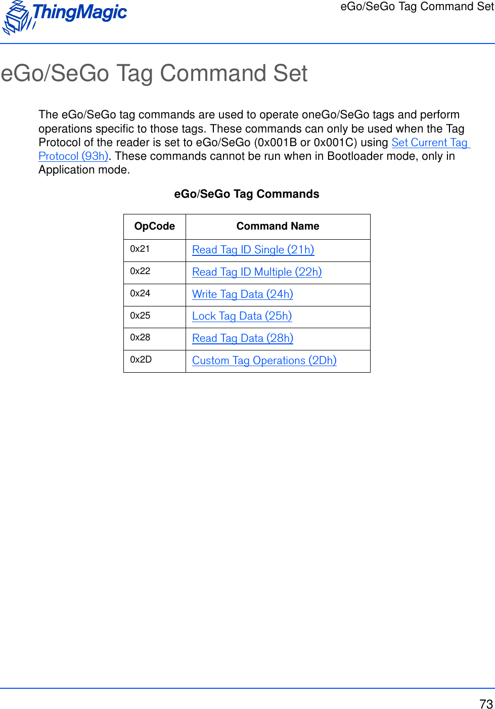
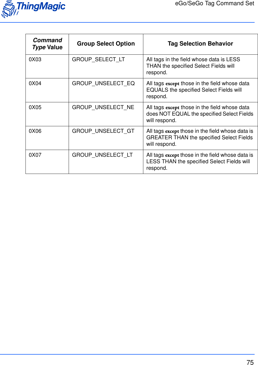
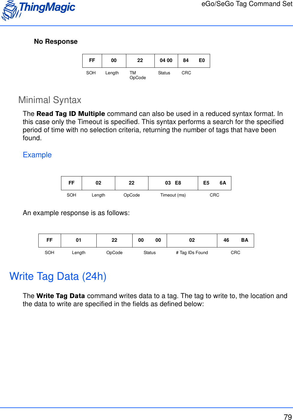
![eGo/SeGo Tag Command Set74Command SyntaxAll eGo/SeGo tag commands follow the same standard syntax. Each command has the following common fields followed by additional fields required for the specific operation being performed:Standard Request FieldsGroup Select OptionsThe following table defines the Command Type values to use for the desired Group Select Option when performing a Read Tag ID Single (21h), Read Tag ID Multiple (22h) or Write Tag Data (24h). The Group Select Option along with the Select Fields (Byte Address, Byte Mask and Word Data) determine which tags will respond to the specified query.Group Select OptionsField Value DescriptionTM OpCode 0xXX TM OpCode as defined in eGo/SeGo Tag Com-mandsTimeout [2 bytes] Indicates how long the command should spend attempting the operation, in milliseconds.TM Options 0x01 Must be set to 0x01, indicating Command Type and eGo/SeGo specific fields to follow. Command Type [1 byte] Depending on the operation indicates either the Group Select Options to apply or a specific sub-command.Command Type Value Group Select Option Tag Selection Behavior0x00 GROUP_SELECT_EQ All tags in the field whose data EQUALS the specified Select Fields will respond.0x01 GROUP_SELECT_NE All tags in the field whose data does NOT EQUAL the specified Select Fields will respond.0X02 GROUP_SELECT_GT All tags in the field whose data is GREATER THAN the specified Select Fields will respond.](https://usermanual.wiki/TransCore/76007.Users-Manual/User-Guide-1204374-Page-74.png)
![eGo/SeGo Tag Command Set76Read Tag ID Single (21h)The Read Tag ID Single command executes a query for tags matching the criteria specified by the Command Type and subsequent fields and returns the first tag found. Read Tag ID Single Request FieldsField Value DescriptionTM OpCode 0x21 TM OpCodeTimeout [2 bytes] Indicates how long the command should spend attempt-ing the operation, in milliseconds.TM Options Bit 0 • 1 - Indicates Command Type and additional fields to follow.Bit 4(LSB=bit 0))• 0 - Metadata flags must not be passed and Meta Data will not be returned. • 1 - Metadata flags must be passed and the corresponding Metadata shall be returned with the tag EPC. Metadata Flags (to specify more than one OR the val-ues together)0x0000 When no flags are set no meta data will be returned, only the tag EPC (including PC bits and tag CRC)0x0001 When bit 0 is set the Read Count will be returned0x0002 When bit 1 is set the LQI/RSSI will be returned0x0004 When bit 2 is set the Antenna ID will be returned0x0008 When bit 3 is set the Frequency will be returned0x0010 When bit 4 is set the Timestamp will be returned0x0020 When bit 5 is set the RFU (ThingMagic Only) will be returned0x0040 When bit 6 is set the Protocol is returned.Command Type [1 byte] Indicates the Group Select criteria to apply as defined in Group Select Options.Byte Address [1 byte]Byte Mask [1 byte]Word Data [8 bytes]](https://usermanual.wiki/TransCore/76007.Users-Manual/User-Guide-1204374-Page-76.png)
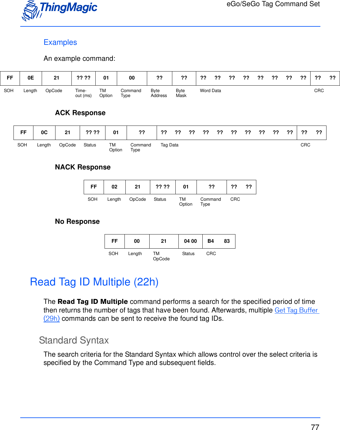
![eGo/SeGo Tag Command Set78Read Tag ID Multiple Request FieldsExamplesAn example command requesting :ACK ResponseNACK ResponseField Value DescriptionTM OpCode 0x22 TM OpCodeTM Options 0x01 Indicates Command Type and additional fields to follow.Search Flags 0x0000 Reserved for Future Use.Timeout [2 bytes] Indicates how long the command should spend attempt-ing the operation, in milliseconds.Command Type [1 byte] Indicates the Group Select criteria to apply as defined in Group Select Options.Byte Address [1 byte]Byte Mask [1 byte]Word Data [8 bytes]FF 10 22 01 00 00 ?? ?? 00 ?? ?? ?? ?? ?? ?? ?? ?? ?? ?? ?? ??SOH Length OpCode TM Option Search Flags Timeout (ms) Command Type Byte Address Byte Mask Word Data CRCFF ?? 22 ?? ?? 01 00 00 ?? ?? ?? ?? ??SOH Length OpCode Status TM Option Search Flags Command Type Tag IDs Detected CRCFF 02 22 ?? ?? 01 ?? ?? ??SOH Length OpCode Status TM Option Command Type CRC](https://usermanual.wiki/TransCore/76007.Users-Manual/User-Guide-1204374-Page-78.png)
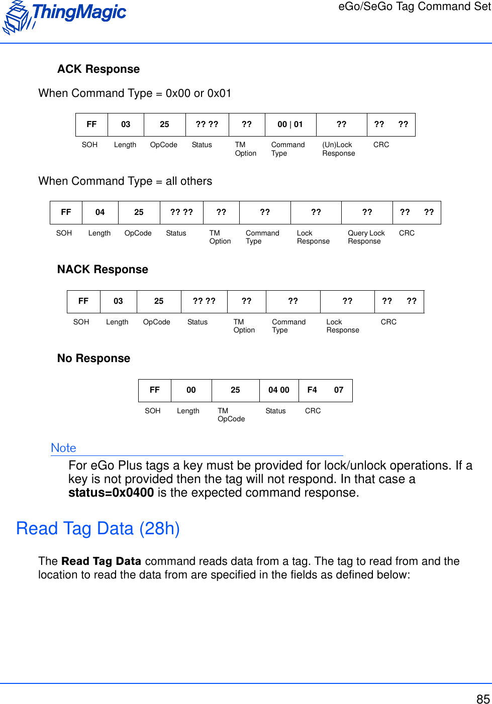
![eGo/SeGo Tag Command Set80Write Tag Data Request FieldsField Value DescriptionTM OpCode 0x24 TM OpCodeTimeout [2 bytes] Indicates how long the command should spend attempt-ing the operation, in milliseconds.TM OptionsNote: TM Options field combines bits 0-4 indicating the verification method and bits 5 & 6 for authentication information. For the final TM Options setting, the two “fields” should be OR’d.[1 byte] excluding bits 5 & 6 (LSB = bit 0)• 0x00 = A READ is executed after the WRITE has reported success for verification. Lock if requested.Note: When 0x00 the Command Type is implicity = 0x0D and the Command Type 1 byte field should be removed from the request command.• 0x01 = No verification is executed after WRITE reports success.• 0x02 = A READ_VERIFY is executed after the WRITE reports success for verification.• 0x03 = Only used with Command Type = 0x0E or 0x93. Indicates extra Select fields will be specified.bits 5 & 6 (LSB = bit 0) Specify authentication method to use:• 0x00 = authentication is disabled and Key values must not be passed.• 0x20 = RFU• 0x40 = authentication is enabled and Key values must be passed.• 0x60 = RFUCommand TypeNote: If TM Options bits 0-4=0 then the Command Type is implicity = 0x0D and this byte should not be specified in the request command.0x0D Indicates the eGo/SeGo Write by Byte operation will be used.0x8D Indicates the eGo/SeGo Write by Page operation will be used0x0E Indicates the eGo/SeGo Write Multiple operation will be used.0x93 Indicates the eGo/SeGo Streamlined Group Select Equal Page Write operation will be used.](https://usermanual.wiki/TransCore/76007.Users-Manual/User-Guide-1204374-Page-80.png)
![eGo/SeGo Tag Command Set81Lock [1 byte] • 0x00 = no lock• 0x01 = lock the data specified by Write DataWrite by Page won’t lock if authentication information is not specified.Write multiple won’t lockWrite Address [1|4byte] Indicates the start address of tag memory to be written:• 4 Byte Address when TM Option = 0xX0• 1 Byte Address otherwiseSelect Command Type [1 byte] Indicates the Group Select criteria to apply as defined in Group Select Options.Only passed when TM Option=0x03. For Command Type = 0x0E, indicates Select TypeFor Command Type = 0x93, RFUSelect Address [1 byte] Only passed when TM Option=0x03. Select Mask [1 byte] Only passed when TM Option=0x03. For Command Type = 0x0E, indicates Select MaskFor Command Type = 0x93, RFUTag ID | Select Data [8 bytes] When:• Command Type = 0x0D, 0x0E or 0x8D: 8 bytes = Tag ID• Command Type = 0x93 AND TM Options=0x03: [1 byte] = Select Data[7 bytes] = RFU• Command Type = 0x93 AND TM Options=0x01 or 0x02[1 byte] = Select Address[1 byte] = Select Data[6 bytes] = RFUWrite Data [1|8 byte] Indicates the data to be written to the specified tag starting at the specified address.• 1 Byte when Command=0x0D and 0x0E• 8 Bytes (1 page) when Command=0x8D and 0x93Key Address [1 byte] Only passed when authentication enabled in TM Options.Key Length in Bytes [1 byte] Only passed when authentication enabled in TM Options.Field Value Description](https://usermanual.wiki/TransCore/76007.Users-Manual/User-Guide-1204374-Page-81.png)
![eGo/SeGo Tag Command Set82ExamplesAn example command requesting :ACK ResponseWhen Command Type = 0x0D or 0x0E,When Command Type = 0x8DWhen Command Type = 0x93NoteACK Status will be:0x0000 FAULT_SUCCESS_CODE0x0403 FAULT_WRITE_PASSED_LOCKED_FAILEDKey [0-N bytes] Only passed when authentication enabled in TM Options.Note: Value passed with MSB first.FF 0F 24 ?? ?? 01 0D ?? ?? ?? ?? ?? ?? ?? ?? ?? ?? ?? ?? ??SOH Length OpCode Timeout (ms) TM Option Command Type Lock Write Address Tag ID Write Data CRCFF 03 24 ?? ?? ?? 0D | OE ?? ?? ??SOH Length OpCode Status TM Option Command Type Verified Write Data CRCFF 0A 24 ?? ?? ?? 8D ?? ?? ?? ?? ?? ?? ?? ?? ?? ??SOH Length OpCode Status TM Option Command Type Verified Write Data CRCFF 13 24 ?? ?? ?? 93 ?? ?? ?? ?? ?? ?? ?? ?? ?? ?? ?? ?? ?? ?? ?? ?? ?? ?? ??SOH Length OpCode Status TM Option Command Type Tag ID Length Tag ID (length defined by ID Length)Verified Write Data CRCField Value Description](https://usermanual.wiki/TransCore/76007.Users-Manual/User-Guide-1204374-Page-82.png)
![eGo/SeGo Tag Command Set83NACK ResponseNo ResponseLock Tag Data (25h)The Lock Tag Data command locks and unlocks a tag’s memory locations. The tag to (un)lock and memory location to be (un)locked are specified in the fields as defined below:Lock Tag Data Request FieldsFF 02 24 ?? ?? 01 0D ?? ??SOH Length OpCode Status TM Option Command Type CRCFF 00 24 04 00 E4 26SOH Length TM OpCode Status CRCField Value DescriptionTM OpCode 0x25 TM OpCodeTimeout [2 bytes] Indicates how long the command should spend attempt-ing the operation, in milliseconds.TM OptionsNote: TM Options field combines bit 0 indicating general processing information and bits 5 & 6 indicating authentication method. For the final TM Options setting, the two “fields” should be OR’d.0x01 Indicates Command Type and additional fields to follow.bits 5 & 6 (LSB = bit 0) Specify authentication method to use:• 0x00 = authentication is disabled and Key values must not be passed.• 0x20 = RFU• 0x40 = authentication is enabled and Key values must be passed.• 0x60 = RFU](https://usermanual.wiki/TransCore/76007.Users-Manual/User-Guide-1204374-Page-83.png)
![eGo/SeGo Tag Command Set84ExamplesAn example command requesting :Command Type 0x00 Performs a QueryLock, immediate followed by an UnLock0x01 Performs a QueryLock, immediate followed by a Lock0x0F LockByte operation. Performs QLock/Lock/QLock0x10 UnLock Byte. Performs QLock/UnLock/QLock0x11 QueryLock0x8F Lock Page. Performs QLock/Lock/QLock0x90 UnLock Page. Performs QLock/UnLock/QLockLock Address [1 byte] Indicates the address of tag memory to be (un)locked.Tag ID [8 byte] Indicates the Tag ID of the tag to be (un)locked.Key Address [1 byte] Only passed when authentication enabled in TM Options.Key Length in Bytes [1 byte] Only passed when authentication enabled in TM Options.Key [0-N bytes] Only passed when authentication enabled in TM Options.Note: Value passed with MSB first.FF 0D 25 ?? ?? 01 0F ?? ?? ?? ?? ?? ?? ?? ?? ?? ?? ??SOH Length OpCode Timeout (ms) TM Option Command Type Lock Address Tag ID CRCField Value Description](https://usermanual.wiki/TransCore/76007.Users-Manual/User-Guide-1204374-Page-84.png)
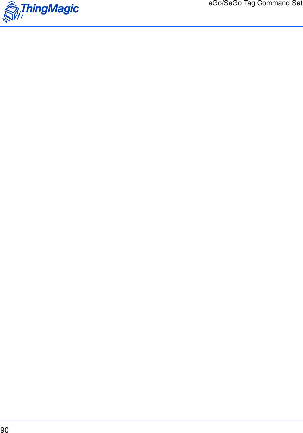
![eGo/SeGo Tag Command Set86Read Tag Data Request FieldsField Value DescriptionTM OpCode 0x28 TM OpCodeTimeout [2 bytes] Indicates how long the command should spend attempting the operation, in milliseconds.TM OptionsNote: TM Options field combines bits 0-4 indicating general processing information and bits 5 & 6 indicating authentication method. For the final TM Options setting, the two “fields” should be OR’d.[1 byte] Indicates Command Type and additional fields to follow:• 0x01 = For Standard Read Operationsbits 5 & 6 (LSB = bit 0) Specify authentication method to use:• 0x00 = authentication is disabled and Key values must not be passed.• 0x20 = RFU• 0x40 = authentication is enabled and Key values must be passed.• 0x60 = RFUCommand Type 0x0C eGo/SeGo Read, or Protected Read0x0B eGo/SeGo Data_Read0x12 eGo/SeGo Read_VerifyNote: Requires a Write to occur immediately before.0x80 eGo/SeGo Streamline_Group_Select_Equal_Page_ReadNote: Only works with eGo Plus tags. 0x92 eGo/SeGo Read_Verify_PageNote: Requires a Write to occur immediately before.RFU [1 byte] Reserved for Future UseRead Byte Count [1 byte] Number of bytes starting at Read Address to read. Can request 1 to 8 bytes.Read Address [1 byte] Indicates the start address of tag memory to be read.](https://usermanual.wiki/TransCore/76007.Users-Manual/User-Guide-1204374-Page-86.png)
![eGo/SeGo Tag Command Set87ExamplesAn example command requesting :ACK ResponseWhen Command Type = 0x80Tag ID | Select Data [8 bytes] When:• Command Type = 0x0B, 0x0C, 0x12 or 0x92: 8 bytes = Tag ID• Command Type = 0x80[1 byte] = Select Address[1 byte] = Select Data[6 bytes] = RFUKey Address [1 byte] Only passed when authentication enabled by TM Options.Key Length in Bytes [1 byte] Only passed when authentication enabled by TM Options.Key [0-N bytes] Only passed when authentication enabled by TM Options.Note: Value passed with MSB first.FF 0F 28 ?? ?? 01 0C ?? ?? ?? ?? ?? ?? ?? ?? ?? ?? ?? ?? ??SOH Length OpCode Timeout (ms) TM Option Command Type RFU Read Byte CountRead Address Tag ID CRCFF ?? 28 ?? ?? 01 0C ?? ?? ??SOH Length OpCode Status TM Option Command Type Read Data CRCFF ?? 28 ?? ?? ?? 80 ?? ?? ?? ?? ?? ?? ?? ?? ?? ?? ?? ?? ?? ?? ?? ?? ?? ?? ??SOH Length OpCode Status TM Option Command Type Tag ID Length Tag ID (length defined by ID Length)Read Data CRCField Value Description](https://usermanual.wiki/TransCore/76007.Users-Manual/User-Guide-1204374-Page-87.png)
![eGo/SeGo Tag Command Set88NACK ResponseNo ResponseCustom Tag Operations (2Dh) The Custom Tag Operations command provides access to several eGo/SeGo tag specific operations including: Fail, Success, Initialize, Resend, Read_All_Data, Read_All_Lock, and RN_Request. The operation to be performed is indicated by the Command Type field:Custom Tag Operations Request FieldsFF 02 28 ?? ?? 01 0C ?? ??SOH Length OpCode Status TM Option Command Type CRCFF 00 28 04 00 25 AASOH Length TM OpCode Status CRCField Value DescriptionTM OpCode 0x2D TM OpCodeTimeout [2 bytes] Indicates how long the command should spend attempting the operation, in milliseconds.TM Options 0x01 Indicates Command Type to follow.Command Type 0x08 Fail0x09 Success0x0A Initialize0x15 Resend0x81 RN Request0x82 Tag Authentication. When specified the Key fields also must be passed.0x83 Mutual Authentication. When specified the Key fields also must be passed.](https://usermanual.wiki/TransCore/76007.Users-Manual/User-Guide-1204374-Page-88.png)
![eGo/SeGo Tag Command Set89ExamplesAn example command requesting :ACK ResponseNACK ResponseNo ResponseKey Address [1 byte] Only passed when Command=0x82 or 0x83.Key Length in Bytes [1 byte] Only passed when Command=0x82 or 0x83.Key [0-N bytes] Only passed when Command=0x82 or 0x83.Note: Value passed with MSB first.FF 04 2D ?? ?? 01 0C ?? ??SOH Length OpCode Timeout (ms) TM Option Command Type CRCFF 05 2D ?? ?? 01 0C ?? ... NN ?? ??SOH Length OpCode Status TM Option Command Type Tag Da ta(0-N based on Command Type)CRCFF 02 2D ?? ?? 01 ?? ?? ??SOH Length OpCode Status TM Option Command Type CRCFF 00 2D 04 00 75 0FSOH Length TM OpCode Status CRCField Value Description](https://usermanual.wiki/TransCore/76007.Users-Manual/User-Guide-1204374-Page-89.png)
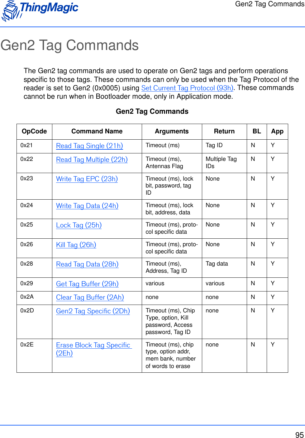
![ATA Tag Command Set91ATA Tag Command SetThe ATA tag commands are used to perform operations specific to ATA tags. These commands can only be used when the Tag Protocol of the reader is set to ATA (0x001D) using Set Current Tag Protocol (93h). These commands cannot be run when in Bootloader mode, only in Application mode. ATA Tag Commands OpCode Command Name0x21 Read Tag ID Single (21h)0x22 Read Tag ID Multiple (22h) [Not yet Implemented]](https://usermanual.wiki/TransCore/76007.Users-Manual/User-Guide-1204374-Page-91.png)
![ATA Tag Command Set92Command SyntaxAll ATA tag commands follow the same standard syntax. Each command has the following common fields followed by additional fields required for the specific operation being performed:Standard Request FieldsField Value DescriptionTM OpCode 0xXX TM OpCode as defined in ATA Tag CommandsTimeout [2 bytes] Indicates how long the command should spend attempting the operation, in milliseconds.](https://usermanual.wiki/TransCore/76007.Users-Manual/User-Guide-1204374-Page-92.png)
![ATA Tag Command Set93Read Tag ID Single (21h)The Read Tag ID Single/Tag Detect command performs a search operation and returns the first ATA tag it finds. Read Tag ID Single Request FieldsExamplesAn example, without TM Options, command:Field Value DescriptionTM OpCode 0x21 TM OpCodeTimeout [2 bytes] Indicates how long the command should spend attempting the operation, in milliseconds.TM OptionsNote: This and following fields are optional.Bit 4(LSB=bit 0))• 0 - Metadata flags must not be passed and Meta Data will not be returned. • 1 - Metadata flags must be passed and the corresponding Metadata shall be returned with the tag EPC. Metadata Flags (to specify more than one OR the val-ues together)0x0000 When no flags are set no meta data will be returned, only the tag EPC.0x0001 When bit 0 is set the Read Count will be returned0x0002 When bit 1 is set the LQI/RSSI will be returned0x0004 When bit 2 is set the Antenna ID will be returned0x0008 When bit 3 is set the Frequency will be returned0x0010 When bit 4 is set the Timestamp will be returned0x0020 When bit 5 is set the RFU (ThingMagic Only) will be returned0x0040 When bit 6 is set the Protocol is returned.FF 02 21 ?? ?? ?? ??SOH Length OpCode Time-out (ms) CRC](https://usermanual.wiki/TransCore/76007.Users-Manual/User-Guide-1204374-Page-93.png)
![ATA Tag Command Set94ACK ResponseNACK ResponseNo ResponseRead Tag ID Multiple (22h)[Not yet implemented]FF 0A 21 ?? ?? ?? ?? ?? ?? ?? ?? ?? ?? ?? ??SOH Length OpCode Status Tag ID CRCFF 00 21 ?? ?? ?? ??SOH Length OpCode Status CRCFF 00 21 04 00 B4 83SOH Length TM OpCode Status CRC](https://usermanual.wiki/TransCore/76007.Users-Manual/User-Guide-1204374-Page-94.png)
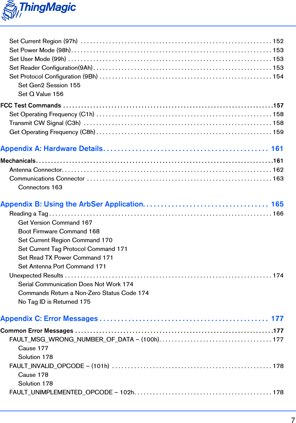
![Gen2 Tag Commands97 0 - Assert (or put in state “A” for inventory flags) the target flag if there IS a match; de-assert (or put in state “B” for inventory flags) the target flag if there IS NOT a match. 4 - Assert (or put in state “A” for inventory flags) the target flag if there IS NOT a match; de-assert (or put in state “B” for inventory flags) the target flag if there IS a matchGen2 Target (Static)This setting determines which inventory flag or SL flag is going to have its state determined by the matching algorithm. Currently always set to ‘4’, indicating the Gen2 Select command modifies a tag’s SL flag.The following table defines the currently supported User Settings and the resulting behavior of the Gen2 Select and Gen2 Query:Gen2 Select and Query BehaviorSelect ProcessThe following defines how the Select process works when attempting to select tags that match a defined criteria:User Settings Select Behavior Query Behavior Comments• Gen2 Session = 0,1,2,3• Invert = 0Gen2 Select Settings:• Target = 4• Action = 0If tags match the criteria, put their SL flag in the ‘Assert’ state; and SL of non-matching tags into the ‘De-assert’ state.Gen2 Query Settings:• SEL = 3• Target = “A”• Session = [User Defined]Ask tags to respond if their SL flag is in the ‘Assert’ state and their session appropriate inventory flag is in the ‘A’ state. Once a tag responds, it puts the inven-tory flag in the ‘B’ state, pre-venting further matches until the inventory flag’s Flag Persistence Rules returns it to the ‘A’ state.Tag state persistence before a Query is based on SL flag persistence; Tag state persistence after a Query is based on inventory flag corre-sponding to the Session used.• Gen2 Session = 0,1,2,3• Invert = 1Gen2 Select Settings:• Target = 4• Action = 4If tags match the criteria, put their SL flag in the ‘De-assert’ state; and SL of non-matching tages into the ‘Assert’ state.](https://usermanual.wiki/TransCore/76007.Users-Manual/User-Guide-1204374-Page-97.png)
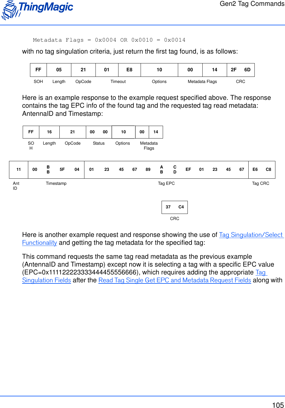
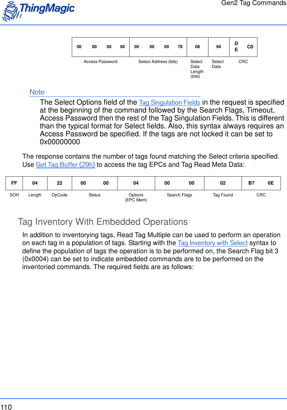
![Gen2 Tag Commands109Tag Inventory with SelectIf you want to inventory only tags meeting a specific criteria this syntax should be used. The search criteria is specified using the Tag Singulation Fields. If Option=0x00 is specified it will perform the same search as the Basic Tag Inventory syntax. Otherwise, it will return the number of tags found matching the specified criteria. The tag EPCs and Meta Data will be available in the Tag Buffer. If no tags are found, a fault code is returned. The required fields are as follows:Read Tag Multiple with Select FieldsHere is an example request and response showing the use of Tag Singulation/Select Functionality to inventory tags which meet a specific criteria:This command will inventory all tags with an EPC value ending in 0x66, which requires adding the appropriate Tag Singulation Fields to the Basic Tag Inventory syntaxField Value DescriptionSelect Options [1 byte] The Options value of the Tag Singulation FieldsSearch Flags [2 bytes] Read Tag Multiple Search Flags indicating antenna usage. Bit 3 must be 0, no embedded commands.Timeout [2 bytes] Indicates how long the command should spend searching.Access Password [4 bytes] The Access Password of the tags expected to be inventoried, if they are locked. If the tags are not locked specify 0x00000000. Note: If the memory used for tag singulation of inventoried flags is read locked and have different passwords, only tags with matching passwords will be successfully inventoried.Tag Singulation Fields The remaining, appropriate fields depending on the value of Select Options.FF 0F 22 04 00 00 03 E8SOH Length OpCode Options(EPC Mem) Search Flags Timeout](https://usermanual.wiki/TransCore/76007.Users-Manual/User-Guide-1204374-Page-109.png)
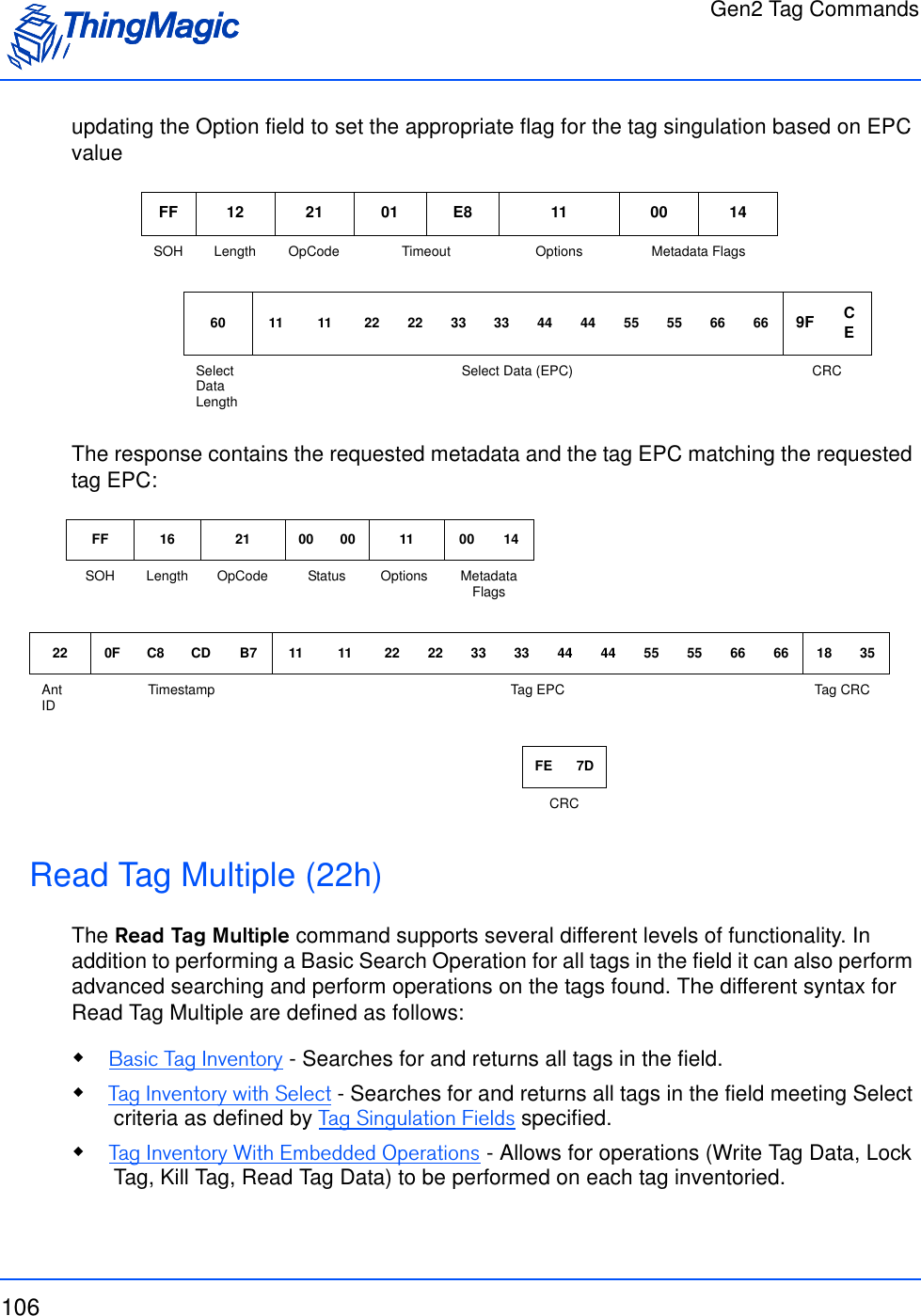
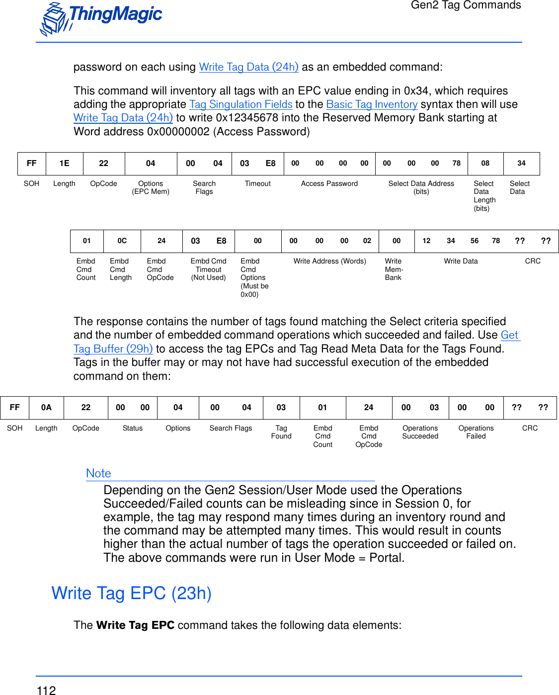
![Gen2 Tag Commands111Read Tag Multiple Embedded Command FieldsHere is an example request and response showing the use of Tag Singulation/Select Functionality to inventory tags which meet a specific criteria and then setting the Access Field Value DescriptionSelect Options [1 byte] The Options value of the Tag Singulation FieldsSearch Flags [2 bytes] Bit 3 of the Read Tag Multiple Search Flags must be set indicating this request contains embedded command(s).Timeout [2 bytes] Indicates how long the command should spend searching AND performing the embedded command. It may be desirable to specify a longer timeout if a large number of tags are likely to get the embedded command executed on them. Access Password [4 bytes] The Access Password of the tags expected to be invento-ried, if they are locked. If the tags are not locked specify 0x00000000. Note: If inventoried flags are locked and have different passwords, only tags with matching passwords will get a successful execution of the embedded command.Tag Singulation Fields The remaining, appropriate fields depending on the value of Select Options.Embedded Command Count [1 byte] The number of embedded commands to follow. [Currently only supports one]Embedded Command Length [1 byte] Length of embedded commands. Follows standard Length value calculation: number of bytes after OpCode.Embedded Command OpCode [1 byte] The OpCode of the embedded command. Currently sup-ports:• Write Tag Data (24h)• Lock Tag (25h)• Kill Tag (26h)• Read Tag Data (28h)The fields and values required by the embed-ded command. Note: The embedded commands do not support Tag Singulation as it is already performed during the inventory operation. The Options field for the embedded command must be 0x00.Note: The Timeout field for embedded commands must be 0x0000.](https://usermanual.wiki/TransCore/76007.Users-Manual/User-Guide-1204374-Page-111.png)
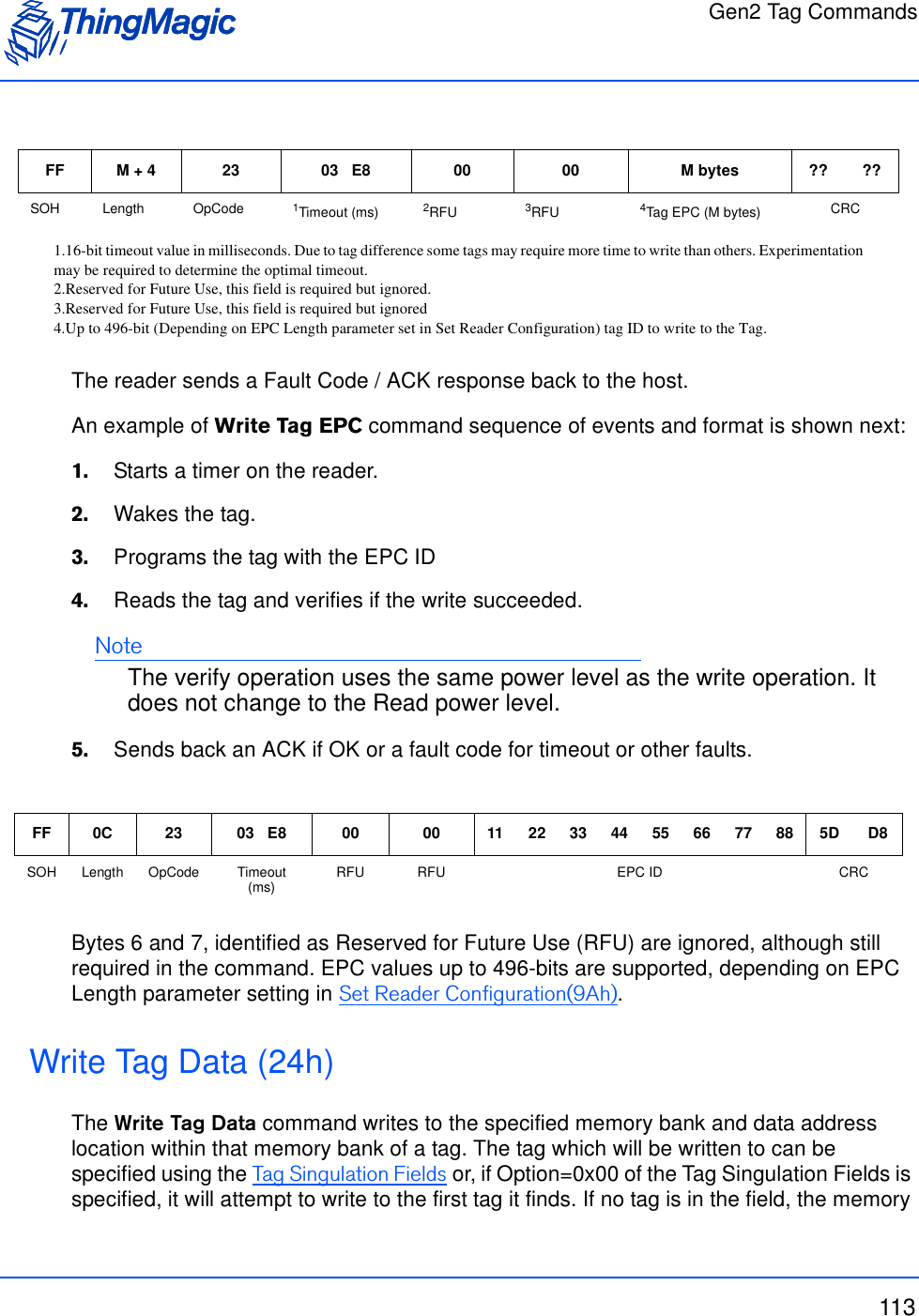
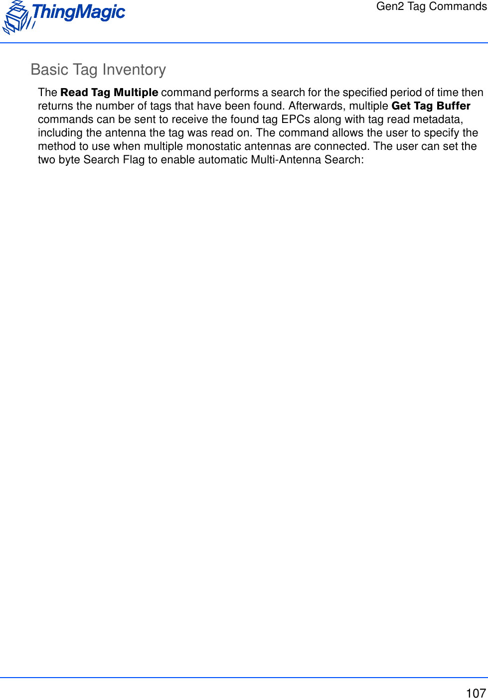
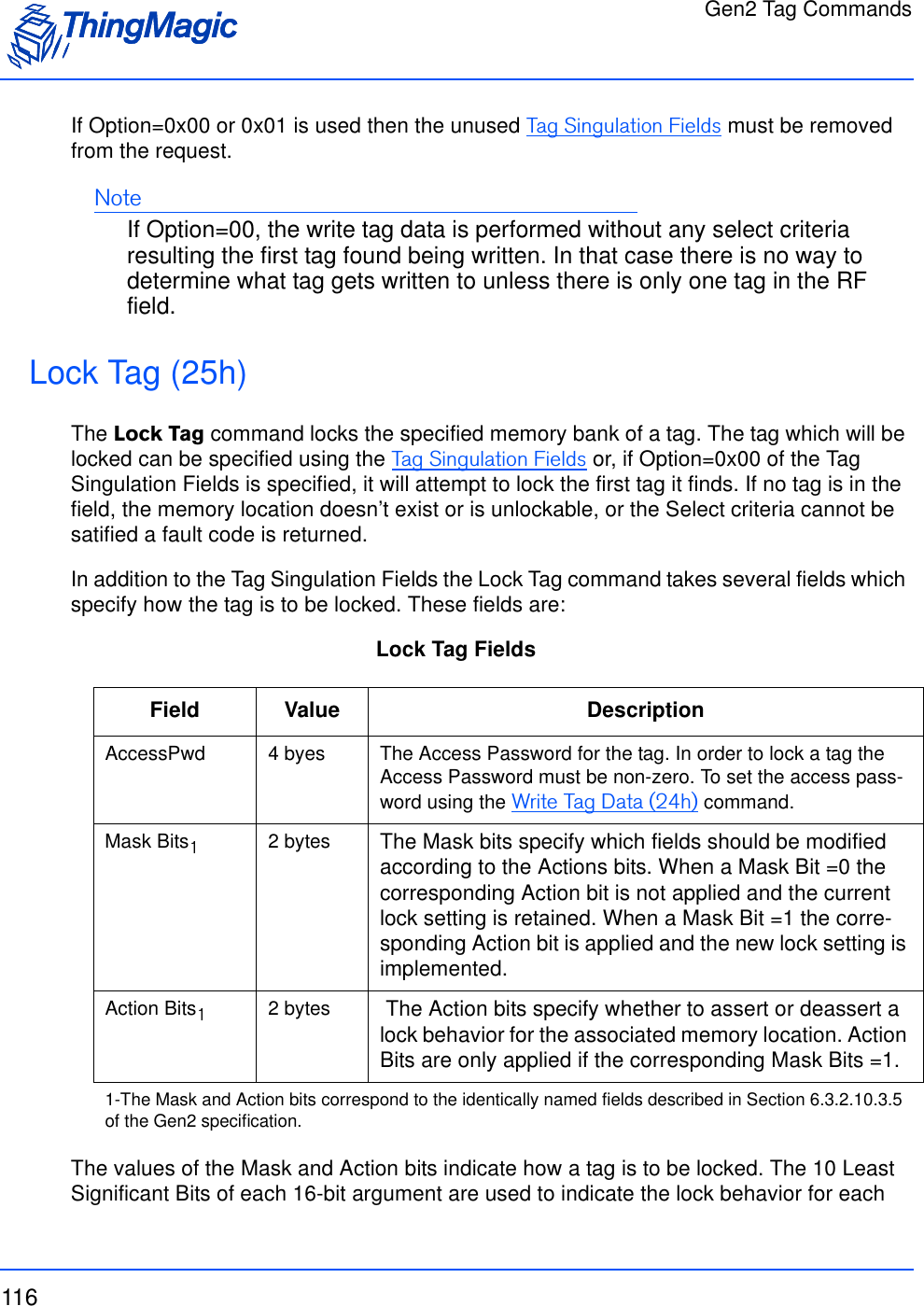
![Gen2 Tag Commands115Write Tag Data FieldsThe following example will attempt to write to Reserved Memory to set the Kill password=0x11112222. It will write this data to a tag matching the following criteria for a max timeout of 1000 ms.Memory Bank = User Memory. Starting Address = bit 32 Select Data = 0x1234The Reserved Memory bank is not locked so the Access Password is zeroField Value DescriptionWrite Address 4 bytes The Address field is the offset in the specified Memory Bank, in 16-bit words, where the contents of the Data field is written. It cor-responds to the WordPtr argument in the Gen2 specification. Note: Addresses are always zero-based. Specifying 0x00 indicates starting at the first address location.Write MemBank 1 byte The MemBank field specifies which of the tag’s memory banks the data is to be written to. The values correspond to the Memory Bank values as specified in the Gen2 specification. They are:0x00 = Reserved0x01 = EPC0x02= TID0x03 = User MemoryWrite Data N bytes The data to be written to the tag in Memory bank [MemBank] starting at address [Address].Access Password 4 byes The Access Password for the tag, if the tag is locked. For an unlocked tag AccessPwd=0x00000000.Note: When Option=0x00 is specified the Access Password is not used.FF 17 24 03 E8 03 00 00 00 00 00 00 00 00 00 00 00 00 20 10 12 34SOH Length OpCode Time-out (ms) Option Write Address Write MemBank Access Password Select Address Select Data LengthSelect Data11 11 22 22 3E 71Write Data CRC](https://usermanual.wiki/TransCore/76007.Users-Manual/User-Guide-1204374-Page-115.png)
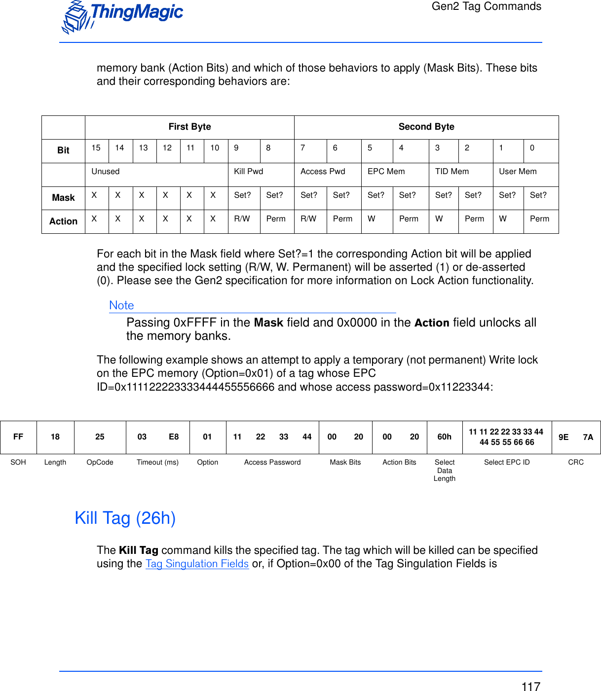
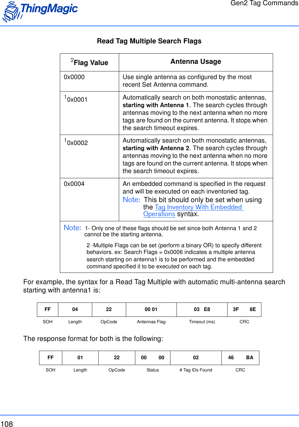
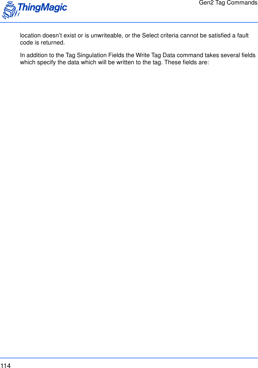
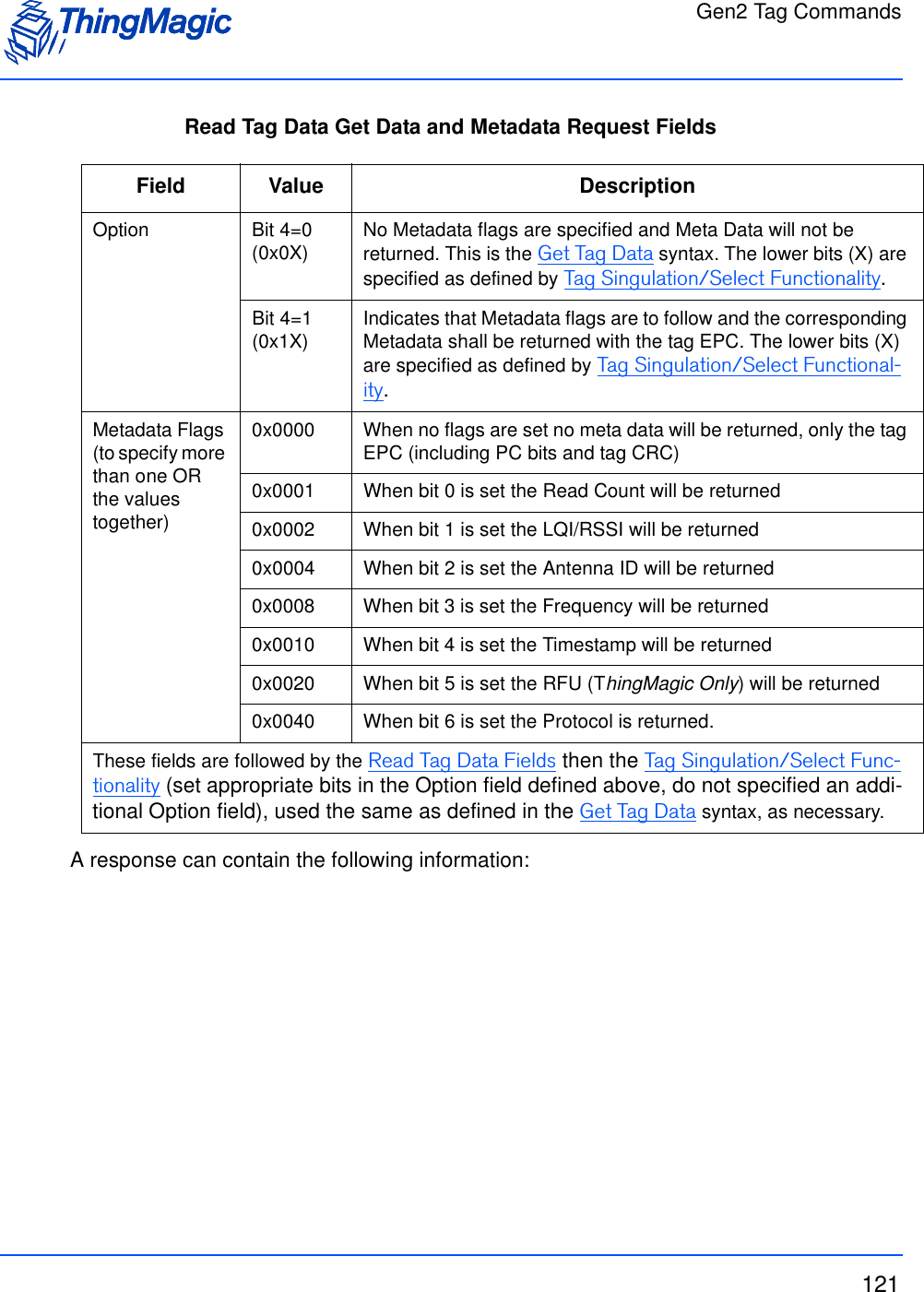
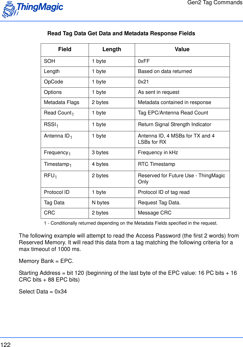
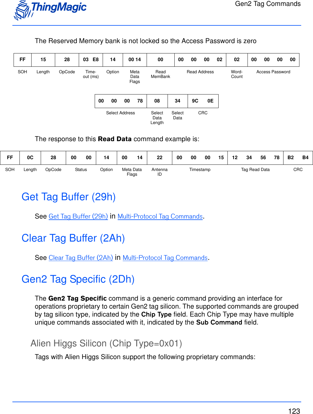
![Gen2 Tag Commands119Read Tag Data FieldsThe Basic syntax which returns only the requested Tag Data is defined in Get Tag Data. With additional Option bits set, Read Tag Data can also return Tag Read Meta Data using the syntax in Get Tag Data and Meta Data.Field Value DescriptionRead MemBank 1 byte The MemBank field specifies which of the tag’s memory banks the data is to be read from. The values correspond to the Memory Bank values as specified in the Gen2 specification. They are:0x00 = Reserved0x01 = EPC0x02= TID0x03 = User MemoryRead Address 4 bytes The Address field is the offset in the specified Memory Bank, in 16-bit words, to start reading from. It corresponds to the WordPtr argument in the Gen2 specification. Note: Addresses are always zero-based. Specifying 0x00 indicates starting at the first address location.WordCount 1 byte The number of words (16 bit chunks) of data to read from memory bank [MemBank] starting at offset [ReadAddress].Access Pass-word 4 byes The Access Password for the tag, if the tag is read locked. For an unlocked tag AccessPwd=0x00000000.](https://usermanual.wiki/TransCore/76007.Users-Manual/User-Guide-1204374-Page-119.png)
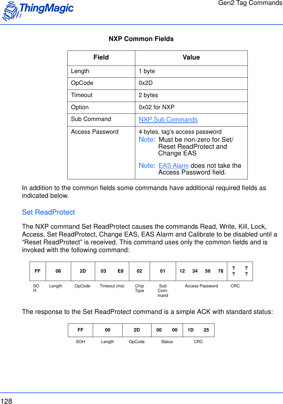
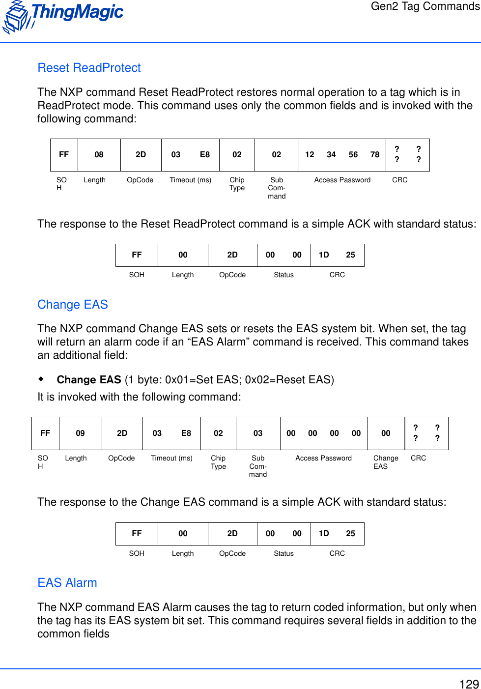
![Gen2 Tag Commands130 Divide Ratio as Per Gen2 (DR) (1 byte: Current fixed to 0x01, M5e and M5e-C only support DR=64/3) Miller Cycles (M) (1 byte: Current fixed to 0x02, M5e and M5e-C only support M=4) TrExt as Per Gen2 (1 byte: Current fixed to 0x01, M5e and M5e-C only support extended Pilot Tone)It is invoked with the following command:The response to the EAS Alarm command contains 8 bytes of EAS Alarm Data, only if Status=0x0000. The format of the response is:CalibrateThe NXP command Calibrate causes the tag to return a random data pattern that is useful in some frequency spectrum measurements. This command uses only the common fields and is invoked with the following command:The response to the Calibrate command contains 32 bytes of Calibrate Data, only if Status=0x0000. The format of the response is:FF 07 2D 03 E8 02 04 01 02 01 ????SOHLength OpCode Timeout (ms) Chip Type Sub Com-mandDR M TrExtCRCFF 0A 2D 00 00 02 04 [8 bytes] ?? ??SOH Length OpCode Status Chip Type Sub Com-mand[EAS Alarm Data] CRCFF 08 2D 03 E8 02 05 11 11 22 22 ????SOHLength OpCode Timeout (ms) Chip Type Sub Com-mandAccess Password CRCFF 42 2D 00 00 02 05 [64 bytes] ?? ??SOH Length OpCode Status Chip Type Sub Com-mand[Calibrate Data] CRC](https://usermanual.wiki/TransCore/76007.Users-Manual/User-Guide-1204374-Page-130.png)
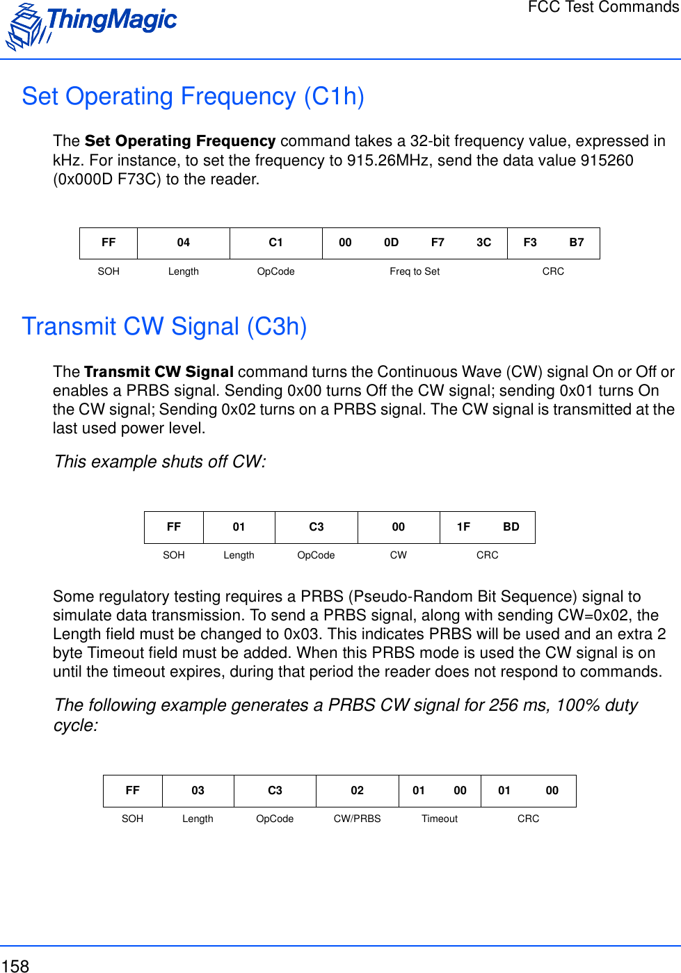
![FCC Test Commands157FCC Test CommandsThe following OpCodes are used for test purposes including regulatory certification testing. These commands cannot be run in the Bootloader. NoteSet Power Mode to Full 0x00 before running FCC commands.FCC Test CommandsOpCode Command Name Arguments Return BL App0xC1 Set Operating Frequency (C1h)Frequency in kHz none N Y0xC3 Transmit CW Signal (C3h) CW mode, [tim-eout] none N Y](https://usermanual.wiki/TransCore/76007.Users-Manual/User-Guide-1204374-Page-157.png)

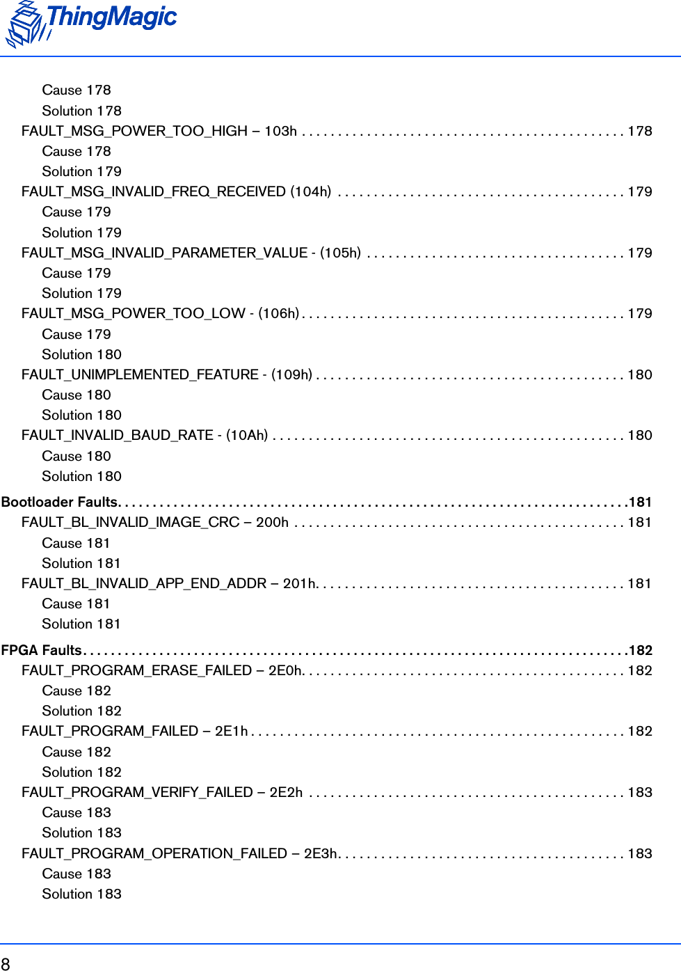
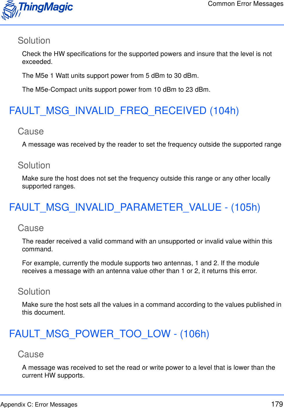
![Appendix B: Using the ArbSer Application 167Get Version CommandWhen the unit is first powered up, the boot loader is running. Verify that the module is alive by sending a Get Version command:C:\> ArbSer –ver< Equivalent to: FF 00 03 1D 0c >Valid message received: Data Length = 14 OpCode = 03 Status = 00 00 Data[000] = 03 Data[001] = 01 Data[002] = 00 Data[003] = 05 Data[004] = FF Data[005] = FF Data[006] = FF Data[007] = FF Data[008] = 20 Data[009] = 04 Data[010] = 11 Data[011] = 03 Data[012] = 03 Data[013] = 01 Data[014] = 00 Data[015] = 06 Data[016] = 00](https://usermanual.wiki/TransCore/76007.Users-Manual/User-Guide-1204374-Page-167.png)
![168 Appendix B: Using the ArbSer Application Data[017] = 00 Data[018] = 00 Data[019] = 07 CRC = 42EAThe module returns its version information. In the previous example, the version number shows the following: Boot loader version #3.1.5 Application FW build date: 11/03/2004 Application FW version #3.1.6 3 protocols enabled (EPC0, EPC1, ISO18000-6B).Boot Firmware CommandNext, send a Boot Firmware command:C:\> ArbSer –go< Equivalent to: FF 00 04 1D 0B >](https://usermanual.wiki/TransCore/76007.Users-Manual/User-Guide-1204374-Page-168.png)
![Appendix B: Using the ArbSer Application 169Valid message received: Data Length = 14 OpCode = 04 Status = 00 00 Data[000] = 03 Data[001] = 01 Data[002] = 00 Data[003] = 05 Data[004] = FF Data[005] = FF Data[006] = FF Data[007] = FF Data[008] = 20 Data[009] = 04 Data[010] = 11 Data[011] = 03 Data[012] = 03 Data[013] = 01 Data[014] = 00 Data[015] = 06 Data[016] = 00 Data[017] = 00 Data[018] = 00 Data[019] = 07 CRC = 4B6A](https://usermanual.wiki/TransCore/76007.Users-Manual/User-Guide-1204374-Page-169.png)
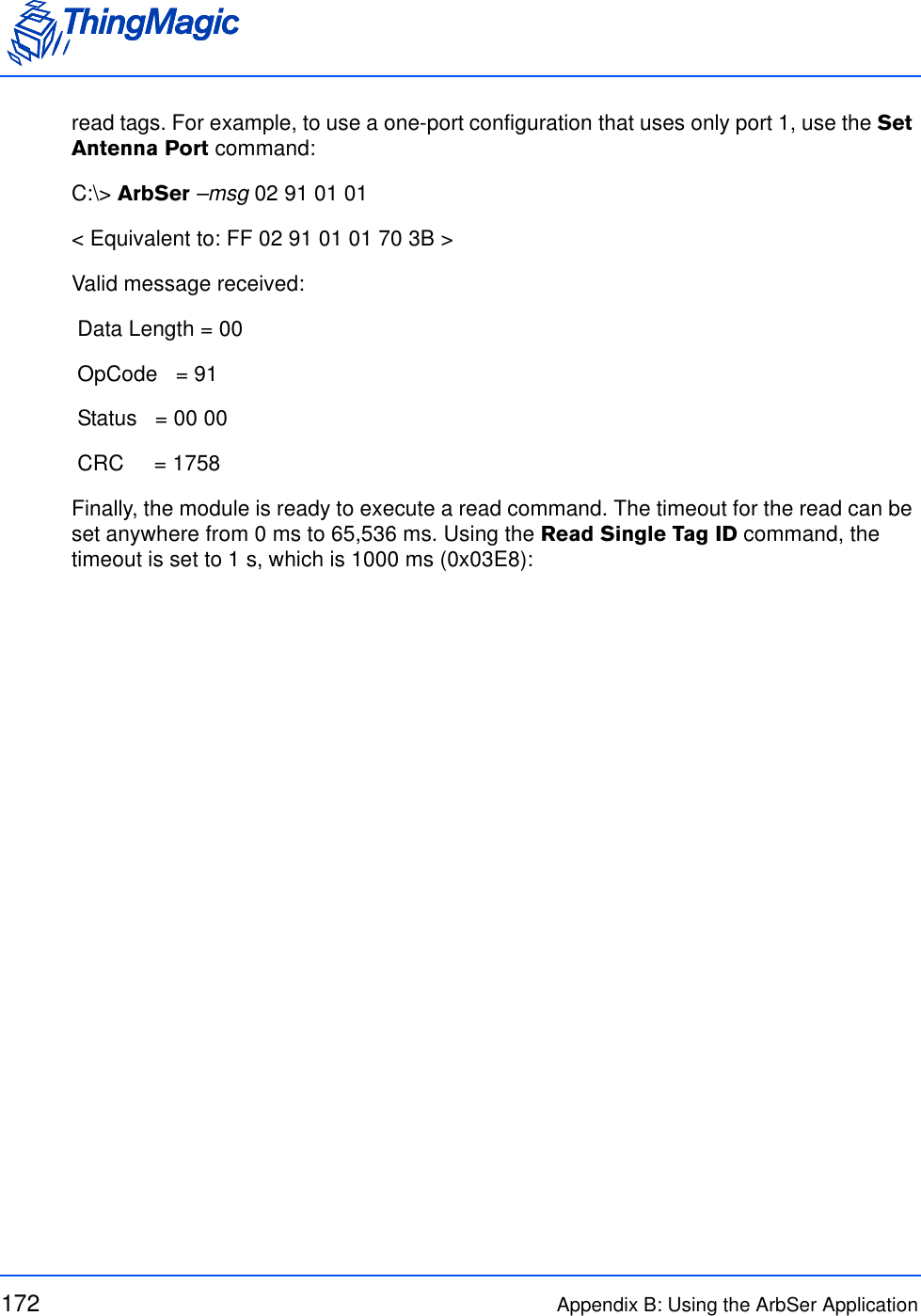
![Appendix B: Using the ArbSer Application 173C:\> ArbSer –msg 02 21 03 E8< Equivalent to: FF 02 21 03 E8 D5 09 >Valid message received: Data Length = 0E OpCode = 21 Status = 00 00 Data[000] = 12 Data[001] = 34 Data[002] = 56 Data[003] = 78 Data[004] = 9A Data[005] = BC Data[006] = DE Data[007] = F0 Data[008] = AA Data[009] = BB Data[010] = CC Data[011] = DD Data[012] = 23 Data[013] = 79 CRC = 2384The module should now return the tag ID of the tag. In this example, the 96-bit EPC0 tag ID is (0x12 34 56 78 9A BC DE F0 AA BB CC DD) with a tag ID CRC of 0x2379.](https://usermanual.wiki/TransCore/76007.Users-Manual/User-Guide-1204374-Page-173.png)
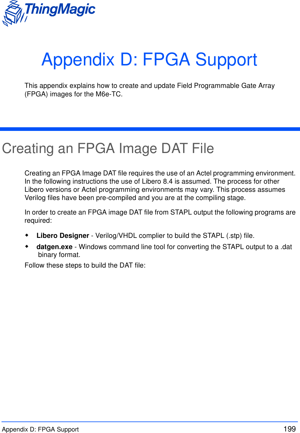
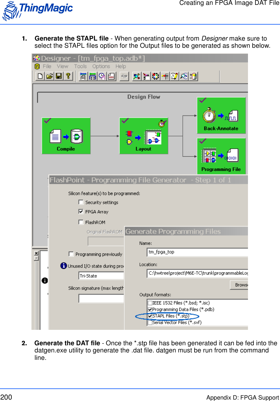
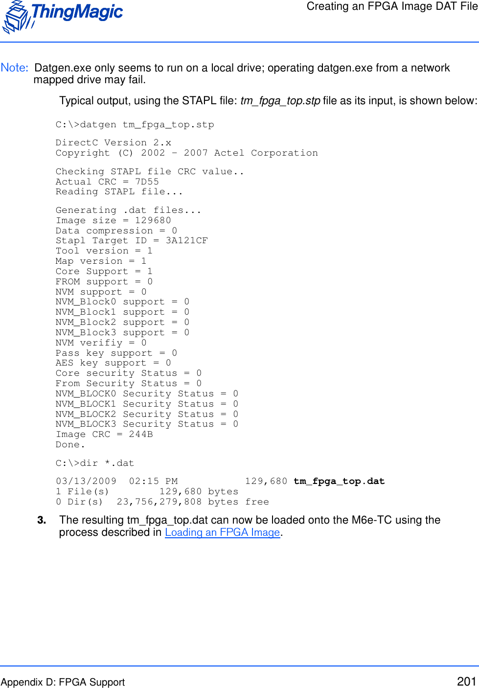
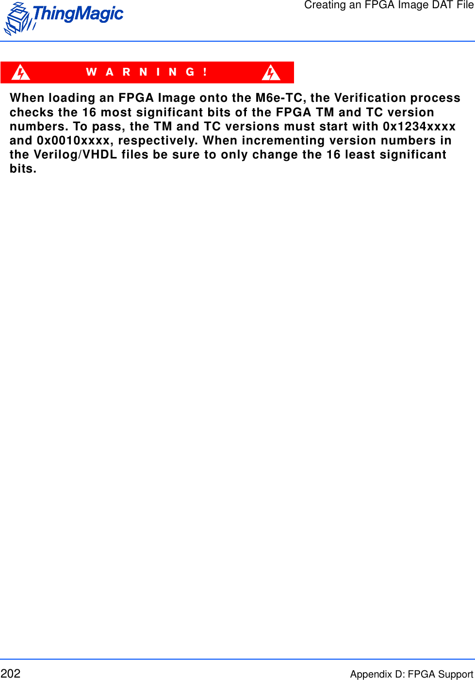
![Loading an FPGA ImageAppendix D: FPGA Support 203Loading an FPGA ImageThe ArbSer (see Appendix B: Using the ArbSer Application) program can also be used to load FPGA images. In order to load an FPGA image the following files are required: Arbser.exe - minimum version 3.2.0. m6etc_fpga_mod.sim - FPGA load application image to be loaded into the M6e-TC which will be used to update the FPGA image defined by the FPGA Image file. FPGA Image file - FPGA image file in DAT format to be loaded into the M6e-TC FPGA. The following describes how to load an image onto the M6e-TC FPGA. These steps must be followed carefully. If FPGA Faults occur please follow the suggested solution and retry the image load.1. Load the FPGA load application program into the M6e-TC using the following command:> arbser -l5a m6etc_fpga_mod.sim2. Load the FPGA image file into flash within the application sector at address 0x8000. > arbser -l5f [fpgaimage.dat] 80003. Initiate the image load. > arbser -goThis executes the FPGA application program and starts the FPGA programming process. The FPGA’s FlashROM is erased, the FPGA image is loaded and, finally, the image is verified (see Note below). This operation takes about three minutes to complete and should not be interrupted. On successful completion the FPGA version information is verified and write and read verify operations are performed to check the ATMEL <> FPGA interface. If these checks pass, the M6e-TC responds with status and version information similar to the response for the Get Version Command but with opcode=0x04 and the module returns to the Boot Loader mode.4. Once the FPGA load has successfully completed the M6e-TC Application firmware must be reloaded using the following command:> arbser -l5a [M6e-TC App Firmware .sim]For FPGA version information use the Get Hardware Version (10h) command..](https://usermanual.wiki/TransCore/76007.Users-Manual/User-Guide-1204374-Page-203.png)
