TransCore 76007 FHSS TRANSCEIVER MODULE User Manual 4
TransCore FHSS TRANSCEIVER MODULE 4
Contents
- 1. Users Manual
- 2. User Manual 1
- 3. User Manual 2
- 4. User Manual 3
- 5. User Manual 4
User Manual 4

79
5.0 UPC Types
NOTE: To minimize the risk of invalid data transmission, we rec-
ommend selecting whether to read or ignore supplemental
characters.
5.1.7 Decode UPC/EAN Supplementals :
Parameter # 0x10
Supplementals are appended characters (2 or 5) according to specic code
format conventions (e.g., UPC A+2, UPC E+2). To enable or disable EAN-
13, scan the appropriate bar code below.:
• If Decode UPC/EAN with Supplemental characters is selected, the
scanner does not decode UPC/EAN symbols without supplemental
characters.
• IfIgnoreUPC/EANwithSupplementalcharactersisselected,andthe
SE-955 is presented with a UPC/EAN symbol with a supplemental,
the scanner decodes the UPC/EAN and ignores the supplemental
characters.
• IfAutodiscriminateUPC/EAN Supplementals is selected, scanDe-
code UPC/EAN Supplemental Redundancy on page 8-25, then select
a value from the numeric bar codes beginning on page 8-71. A value
of 5 or more is recommended.
• Select Enable378/379 Supplemental Mode to enablethe SE-955 to
identify supplementals for EAN-13 bar codes starting with a ‘378’ or
‘379’ prex only. All other UPC/EAN bar codes are decoded immedi-
ately and the supplemental characters ignored.
Decode UPC/EAN With Supplementals
(0x01)
Autodiscriminate UPC/EAN Supplementals
(0x02)
Enable 378/379 Supplemental Mode
(0x04)
*Ignore UPC/EAN With Supplementals
(0x00)
• SelectEnable978SupplementalModetoenabletheSE-955toiden-
tify supplementals for EAN-13 bar codes starting with a ‘978’ prex
only. All other UPC/EAN bar codes are decoded immediately and the
supplemental characters ignored.
• SelectEnableSmartSupplementalModetoenabletheSE-955toiden-
tify supplementals for EAN-13 bar codes starting with a ‘378’, ‘379’, or
‘978’ prex only. All other UPC/EAN bar codes are decoded immedi-
ately and the supplemental characters ignored.
Enable 978 Supplemental Mode
(0x05)
Enable Smart Supplemental Mode
(0x03)
Decode UPC/EAN Supplemental Redundancy
(Default: 7)
5.1.8 Decode UPC/EAN Supplemental Redun-
dancy : Parameter # 0x50
With Autodiscriminate UPC/EAN Supplementals selected, this option
adjusts the number of times a symbol without supplementals will be de-
coded before transmission. e range is from 2 to 30 times. Five or above
is recommended when decoding a mix of UPC/EAN symbols with and
without supplementals, and the autodiscriminate option is selected.
Scan the bar code below to select a decode redundancy value. Next scan
two numeric bar codes beginning on page 8-71. Single digit numbers
must have a leading zero. To change the selection or cancel an incorrect
entry, scan the Cancel bar code on page 8-72.

80
5.0 UPC Types
5.1.9 Transmit UPC-A Check Digit :
Parameter # 0x28
Scan the appropriate bar code below to transmit the symbol with or
without the UPC-A check digit.
5.1.10 Transmit UPC-E Check Digit :
Parameter # 0x29
Scan the appropriate bar code below to transmit the symbol with or
without the UPC-E check digit.
*Transmit UPC-A Check Digit
(0x01)
*Transmit UPC-E Check Digit
(0x01)
Do Not Transmit UPC-A Check Digit
(0x00)
Do Not Transmit UPC-E Check Digit
(0x00)
5.1.11 Transmit UPC-E1 Check Digit :
Parameter # 0x2A
Scan the appropriate bar code below to transmit the symbol with or
without the UPC-E1 check digit.
5.1.12 UPC-A Preamble :
Parameter # 0x22
Preamble characters (Country Code and System Character) can be
transmitted as part of a UPC-A symbol. Select one of the following op-
tions for transmitting UPC-A preamble to the host device: transmit sys-
tem character only, transmit system character and country code (“0” for
USA), or transmit no preamble.
*Transmit UPC-A Check Digit
(0x01)
No Preamble
(<DATA>)
(0x00)
Do Not Transmit UPC-A Check Digit
(0x00)
*System Character
(<SYSTEM CHARACTER> <DATA>)
(0x01)
System Character & Country Code
(< COUNTRY CODE> <SYSTEM CHARACTER> <DATA>)
(0x02)
5.1.13 UPC-E Preamble :
Parameter # 0x23
Preamble characters (Country Code and System Character) can be
transmitted as part of a UPC-E symbol. Select one of the following op-
tions for transmitting UPC-E preamble to the host device: transmit sys-
tem character only, transmit system character and country code (“0” for
USA), or transmit no preamble.
No Preamble
(<DATA>)
(0x00)
*System Character
(<SYSTEM CHARACTER> <DATA>)
(0x01)
System Character & Country Code
(< COUNTRY CODE> <SYSTEM CHARACTER> <DATA>)
(0x02)

81
5.0 UPC Types
5.1.14 UPC-E1 Preamble :
Parameter # 0x24
Preamble characters (Country Code and System Character) can be
transmitted as part of a UPC-E1 symbol. Select one of the following
options for transmitting UPC-E1 preamble to the host device: transmit
system character only, transmit system character and country code (“0”
for USA), or transmit no preamble.
No Preamble
(<DATA>)
(0x00)
*System Character
(<SYSTEM CHARACTER> <DATA>)
(0x01)
System Character & Country Code
(< COUNTRY CODE> <SYSTEM CHARACTER> <DATA>)
(0x02)
5.1.15 Convert UPC-E to UPC-A :
Parameter # 0x25
Enable this parameter to convert UPC-E (zero suppressed) decoded
data to UPC-A format before transmission. Aer conversion, data fol-
lows UPC-A format and is aected by UPC-A programming selections
(e.g., Preamble, Check Digit).
Scan DO NOT CONVERT UPC-E TO UPC-A to transmit UPC-E (zero
suppressed) decoded data.
5.1.16 Convert UPC-E1 to UPC-A :
Parameter # 0x26
Enable this parameter to convert UPC-E1 (zero suppressed) decoded
data to UPC-A format before transmission. Aer conversion, data fol-
lows UPC-A format and is aected by UPC-A programming selections
(e.g., Preamble, Check Digit).
Scan DO NOT CONVERT UPC-E TO UPC-A to transmit UPC-E1 (zero
suppressed) decoded data.
Convert UPC-E to UPC-A (Enable)
(0x01)
Convert UPC-E1 to UPC-A (Enable)
(0x01)
*Do Not Convert UPC-E to UPC-A (Disable)
(0x00)
*Do Not Convert UPC-E1 to UPC-A (Disable)
(0x00)
5.1.17 EAN Zero Extend :
Parameter # 0x27
When enabled, this parameter adds ve leading zeros to decoded EAN-8
symbols to make them compatible in format to EAN-13 symbols.
Disable this parameter to transmit EAN-8 symbols as is.
Enable EAN Zero Extend
(0x01)
*Disable EAN Zero Extend
(0x00)
5.1.18 Convert EAN-8 to EAN-13 Type :
Parameter # 0xE0
When EAN Zero Extend is enabled, you can label the extended symbol
as either an EAN-13 bar code, or an EAN-8 bar code. is aects
Transmit Code ID Character and DECODE_DATA message.
When EAN Zero Extend is disabled, this parameter has no eect on bar
code data.
*Type Is EAN-13
(0x00)
Type Is EAN-8
(0x01)

82
5.0 UPC Types
5.1.19 UPC/EAN Security Level :
Parameter # 0x4D
e SE-955 oers four levels of decode security for UPC/EAN bar codes.
Increasing levels of security are provided for decreasing levels of bar
code quality. Select higher levels of security for decreasing levels of bar
code quality. Increasing security decreases the scanner’s aggressiveness,
so choose only that level of security necessary for the application.
UPC/EAN Security Level 0: is default setting allows the scanner
to operate in its most aggressive state, while providing sucient security
in decoding most “in-spec” UPC/EAN bar codes.
*UPC/EAN Security Level 0
(0x00)
UPC/EAN Security Level 1
(0x01)
UPC/EAN Security Level 2
(0x02)
UPC/EAN Security Level 3
(0x03)
UPC/EAN Security Level 1: As bar code quality levels diminish,
certain characters become prone to mis-decodes before others (i.e., 1,
2, 7, 8). If mis-decodes of poorly printed bar codes occur, and the mis-
decodes are limited to these characters, select this security level.
UPC/EAN Security Level 2: If mis-decodes of poorly printed bar
codes occur, and the mis-decodes are not limited to characters 1, 2, 7,
and 8, select this security level.
UPC/EAN Security Level 3: If misdecodes still occur aer selecting
Security Level 2, select this security level. Be advised, selecting this op-
tion is an extreme measure against mis-decoding severely out of spec
bar codes. Selection of this level of security signicantly impairs the de-
coding ability of the scanner. If this level of security is necessary, try to
improve the quality of the bar codes.
5.1.20 UCC Coupon Extended Code :
Parameter # 0x55
e UCC Coupon Extended Code is an additional bar code adjacent to a
UCC Coupon Code. To enable or disable UCC Coupon Extended Code,
scan the appropriate bar code below.
Enable UCC Coupon Extended Code
(0x01)
*Disable UCC Coupon Extended Code
(0x00)
5.2 Code 128
5.2.1 Enable/Disable Code 128 :
Parameter # 0x08
To enable or disable Code 128, scan the appropriate bar code below.
5.2.2 Enable/Disable UCC/EAN-128 :
Parameter # 0x0E
To enable or disable UCC/EAN-128, scan the appropriate bar code be-
low. (See Chapter B, Miscellaneous Code Information for details
on UCC/EAN-128.)
*Enable Code 128
(0x01)
*Enable UCC/EAN-128
(0x01)
Disable Code 128
(0x00)
Disable UCC/EAN-128
(0x00)
83
5.0 UPC Types
5.2.3 Enable/Disable ISBT 128 :
Parameter # 0x54
To enable or disable ISBT 128, scan the appropriate bar code below.
5.2.4 Lengths for Code 128
No length setting is required for Code 128.
*Enable ISBT 128
(0x01)
Disable ISBT 128
(0x00)
5.3 Code 39
5.3.1 Enable/Disable Code 39 :
Parameter # 0x00
To enable or disable Code 39, scan the appropriate bar code below.
5.3.2 Enable/Disable Trioptic Code 39 :
Parameter # 0x0D
Trioptic Code 39 is a variant of Code 39 used in marking computer tape
cartridges. Trioptic Code 39 symbols always contain six characters.
To enable or disable Trioptic Code 39, scan the appropriate bar code
below.
*Enable Code 39
(0x01)
Enable Trioptic Code 39
(0x01)
Disable Code 39
(0x00)
*Disable Trioptic Code 39
(0x00)
NOTE: Trioptic Code 39 and Code 39 Full ASCII cannot be enabled
simultaneously. If an error beep sounds when enabling Tri-
optic Code 39, disable Code 39 Full ASCII and try again.
5.3.3 Convert Code 39 to Code 32 (Italian
Pharma Code) :
Parameter # 0x56
Code 32 is a variant of Code 39 used by the Italian pharmaceutical in-
dustry. Scan the appropriate bar code below to enable or disable con-
verting Code 39 to Code 32.
Enable Convert Code 39 to Code 32
(0x01)
NOTE: Code 39 must be enabled in order for this parameter to func-
tion.
5.3.4 Code 32 Prex :
Parameter # 0xE7
Enable this parameter to add the prex character “A” to all Code 32 bar
codes. Convert Code 39 to Code 32 (Italian Pharma Code) must
be enabled for this parameter to function.
Enable Code 32 Prex
(0x01)
*Disable Convert Code 39 to Code 32
(0x00)
*Disable Code 32 Prex
(0x00)
5.3.5 Set Lengths for Code 39 :
Parameter # L1 = 0x12, L2 = 0x13
e length of a code refers to the number of characters (i.e., human read-
able characters), including check digit(s) the code contains. Lengths for
Code 39 may be set for any length, one or two discrete lengths, or lengths
within a specic range. If Code 39 Full ASCII is enabled, Length With-
in a Range or Any Length are the preferred options.
NOTE: When setting lengths, single digit numbers must always be
preceded by a leading zero.

84
5.0 UPC Types
Code 39 - Two Discrete Lengths
Code 39 - Length Within Range
• Two Discrete Lengths - is option limits decodes to only those
Code 39 symbols containing either of two selected lengths. Lengths
are selected from the numeric bar codes in Section 5.5 on page 95.
For example, to decode only those Code 39 symbols containing either
2 or 14 characters, scan Code 39 - Two Discrete Lengths, then scan
0, 2, 1 and then 4. To change the selection or cancel an incorrect entry,
scan Cancel in Section 5.5.1 on page 95.
• Length Within Range - is option limits decodes to only those
Code 39 symbols within a specied range. For example, to decode
Code 39 symbols containing between 4 and 12 characters, rst scan
Code 39 - Length Within Range. en scan 0, 4, 1 and 2. Numeric
bar codes are in Section 5.5 on page 95. To change the selection or
cancel an incorrect entry, scan Cancel in Section 5.5.1 on page 95.
Code 39 - Any Length
• Any Length - Scan this option to decode Code 39 symbols contain-
ing any number of characters.
5.3.6 Code 39 Check Digit Verication :
Parameter # 0x30
When this feature is enabled, the scanner checks the integrity of all
Code 39 symbols to verify that the data complies with specied check
digit algorithm. Only those Code 39 symbols which include a modulo
43 check digit are decoded. Only enable this feature if your Code 39
symbols contain a module 43 check digit.
Verify Code 39 Check Digit
(0x01)
*Do Not Verify Code 39 Check Digit
(0x00)
5.3.7 Transmit Code 39 Check Digit :
Parameter # 0x2B
Scan this symbol to transmit the check digit with the data.
Scan this symbol to transmit data without the check digit.
Verify Code 39 Check Digit
(0x01)
*Do Not Verify Code 39 Check Digit
(0x00)
5.3.8 Enable/Disable Code 39 Full ASCII :
Parameter # 0x11
Code 39 Full ASCII is a variant of Code 39 which pairs characters to
encode the full ASCII character set. To enable or disable Code 39 Full
ASCII, scan the appropriate bar code below.
Refer to Table B-3 on page B-5 for the mapping of Code 39 characters
to ASCII values.
Verify Code 39 Check Digit
(0x01)
*Do Not Verify Code 39 Check Digit
(0x00)
NOTE: Trioptic Code 39 and Code 39 Full ASCII cannot be enabled
simultaneously. If you get an error beep when enabling Code
39 Full ASCII, disable Trioptic Code 39 and try again.
Code 39 - One Discrete Length
• One Discrete Length - is option limits decodes to only those
Code 39 symbols containing a selected length. Lengths are selected
from the numeric bar codes in Section 5.5 on page 95. For exam-
ple, to decode only Code 39 symbols with 14 characters, scan Code
39 - One Discrete Length, then scan 1 followed by 4. To change the
selection or cancel an incorrect entry, scan Cancel in Section 5.5.1
on page 95.

85
5.0 UPC Types
5.4 Code 93
5.4.1 Enable/Disable Code 93 :
Parameter # 0x00
To enable or disable Code 93, scan the appropriate bar code below.
Enable Code 93
(0x01)
*Disable Code 93
(0x00)
5.4.2 Set Lengths for Code 93 :
Parameter # L1 = 0x1A, L2 = 0x1B
e length of a code refers to the number of characters (i.e., human read-
able characters), including check digit(s) the code contains. Lengths for
Code 93 may be set for any length, one or two discrete lengths, or lengths
within a specic range.
• One Discrete Length - Select this option to decode only those
codes containing a selected length. For example, select Code 93 -
One Discrete Length, then scan 1, 4 to limit the decoding to only
Code 93 symbols containing 14 characters. Numeric bar codes are
in Section 5.5 on page 95. To change the selection or cancel an
incorrect entry, scan Cancel in Section 5.5.1 on page 95.
Code 93 - One Discrete Length
Code 93 - Two Discrete Lengths
• Two Discrete Lengths - Select this option to decode only those
codes containing two selected lengths. For example, select Code 39
- Two Discrete Lengths, then scan 0, 2, 1, 4 to limit the decoding
to only Code 93 symbols containing 2 or 14 characters. Numeric bar
codes are in Section 5.5 on page 95. To change the selection or
cancel an incorrect entry, scan Cancel in Section 5.5.1 on page 95.
Code 93 - Length Within Range
• Length Within Range - is option sets the unit to decode a code
type within a specied range. For example, to decode Code 93 symbols
containing between 4 and 12 characters, rst scan Code 39 - Length
Within Range. en scan 0, 4, 1 and 2 (single digit numbers must
always be preceded by a leading zero). Numeric bar codes are in Sec-
tion 5.5 on page 95. To change the selection or cancel an incorrect
entry, scan Cancel in Section 5.5.1 on page 95.
Code 93 - Any Length
• Any Length - Scan this option to decode Code 93 symbols contain-
ing any number of characters.
5.5 Code 11
5.5.1 Enable/Disable Code 11 :
Parameter # 0x0A
To enable or disable Code 11, scan the appropriate bar code below.
Enable Code 11
(0x01)
*Disable Code 11
(0x00)
5.5.2 Set Lengths for Code 11 :
Parameter # L1 = 0x1C, L2 = 0x1D
e length of a code refers to the number of characters (i.e., human read-
able characters), including check digit(s) the code contains. Set lengths
for Code 11 to any length, one or two discrete lengths, or lengths within
a specic range.
• OneDiscreteLength - Select this option to decode only Code 11
symbols containing a selected length. Select the length using the nu-
meric bar codes in Numeric Bar Codes in Section 5.5 on page 95.
For example, to decode only Code 11 symbols with 14 characters,
scan Code 11 - One Discrete Length, then scan 1 followed by 4. To
correct an error or to change the selection, scan Cancel in Section
5.5.1 on page 95.
Code 11 - One Discrete Length
Code 11 - Two Discrete Lengths
• Two Discrete Lengths - Select this option to decode only Code 11
symbols containing either of two selected lengths. Select lengths us-
ing the numeric bar codes in Numeric Bar Codes on page 8-76. For ex-
ample, to decode only those Code 11 symbols containing either 2 or 14
characters, select Code 11 - Two Discrete Lengths, then scan 0, 2, 1,
and then 4. To correct an error or to change the selection, scan Cancel
in Section 5.5.1 on page 95.
86
5.0 UPC Types
Code 11 - Length Within Range
Length Within Range - Select this option to decode a Code 11 sym-
bol with a specic length range. Select lengths using numeric bar codes
in Numeric Bar Codes on page 8-76. For example, to decode Code 11
symbols containing between 4 and 12 characters, rst scan Code 11
- Length Within Range. en scan 0, 4, 1, and 2 (single digit num-
bers must always be preceded by a leading zero). To correct an error or
change the selection, scan Cancel in Section 5.5.1 on page 95.
Code 11 - Any Length
Any Length - Scan this option to decode Code 11 symbols containing
any number of characters within the scanner capability.
5.5.3 Code 11 Check Digit Verication :
Parameter # 0x34
is feature allows the scanner to check the integrity of all Code 11
symbols to verify that the data complies with the specied check digit
algorithm. is selects the check digit mechanism for the decoded Code
11 bar code. e options are to check for one check digit, check for two
check digits, or disable the feature.
To enable this feature, scan the bar code below corresponding to the
number of check digits encoded in your Code 11 symbols.
*Disable
(0x00)
One Check Digit
(0x01)
Two Check Digits
(0x02)
5.5.4 Transmit Code 11 Check Digits :
Parameter # 0x2F
is feature selects whether or not to transmit the Code 11 check digit(s).
Transmit Code 11 Check Digit(s) (Enable)
(0x01)
*Do Not Transmit Code 11 Check Digit(s) (Disable)
(0x00)
NOTE: Code 11 Check Digit Verication must be enabled for this pa-
rameter to function.
*Enable Interleaved 2 of 5
(0x01)
Disable Interleaved 2 of 5
(0x00)
5.6 Interleaved 2 of 5
5.6.1 Enable/Disable Interleaved 2 of 5 :
Parameter # 0x06
To enable or disable Interleaved 2 of 5, scan the appropriate bar code
below.
5.6.2 Set Lengths for Interleaved 2 of 5 :
Parameter # L1 = 0x16, L2 = 0x17
e length of a code refers to the number of characters (i.e., human read-
able characters), including check digit(s) the code contains. Lengths for
I 2 of 5 may be set for any length, one or two discrete lengths, or lengths
within a specic range.
NOTE: When setting lengths, single digit numbers must always be
preceded by a leading zero.
87
5.0 UPC Types
I 2 of 5 - One Discrete Length
I 2 of 5 - Two Discrete Lengths
• One Discrete Length - Select this option to decode only those codes
containing a selected length. For example, select I 2 of 5 - One Dis-
crete Length, then scan 1, 4, to decode only I 2 of 5 symbols con-
taining 14 characters. Numeric bar codes are in Section 5.5 on page
95. To change the selection or cancel an incorrect entry,scan Cancel
in Section 5.5.1 on page 95.
• Two Discrete Lengths - Select this option to decode only those
codes containing two selected lengths. For example, select I 2 of 5 -
Two Discrete Lengths, then scan 0, 6, 1, 4 to decode only I 2 of 5
symbols containing 6 or 14 characters. Numeric bar codes begin on
page 8-71. To change the selection or cancel an incorrect entry, scan
Cancel in Section 5.5.1 on page 95.
I 2 of 5 - Length Within Range
• Length Within Range - Select this option to decode only codes
within a specied range. For example, to decode I 2 of 5 symbols
containing between 4 and 12 characters, rst scan I 2 of 5 - Length
Within Range. en scan 0, 4, 1 and 2 (single digit numbers must
always be preceded by a leading zero). Numeric bar codes begin are in
Section 5.5 on page 95. To change the selection or cancel an incor-
rect entry, scan Cancel in Section 5.5.1 on page 95.
I 2 of 5 - Any Length
• Any Length - Scan this option to decode Code 39 symbols contain-
ing any number of characters.
NOTE: Selecting this option may lead to misdecodes for I 2 of 5
codes.
5.6.3 Interleaved 2 of 5 Check Digit Verica-
tion :
Parameter # 0x31
When enabled, this parameter checks the integrity of an I 2 of 5 symbol
to ensure it complies with a specied algorithm, either USS (Uniform
Symbology Specication), or OPCC (Optical Product Code Council).
*Disable
(0x00)
USS Check Digit
(0x01)
OPCC Check Digit
(0x02)
5.6.4 Transmit Interleaved 2 of 5 Check Digit:
Parameter # 0x2C
Scan this symbol to transmit the check digit with the data.
5.6.5 Convert Interleaved 2 of 5 to EAN-13 :
Parameter # 0x52
is parameter converts a 14 character I 2 of 5 code into EAN-13, and
transmits to the host as EAN-13. To accomplish this, I 2 of 5 must be
enabled, one length must be set to 14, and the code must have a leading
zero and a valid EAN-13 check digit.
Scan this symbol to transmit data without the check digit.
*Do Not Transmit I 2 of 5 Check Digit (Disable)
(0x00)
*Do Not Convert I 2 of 5 to EAN-13 (Disable)
(0x00)
Transmit I 2 of 5 Check Digit (Enable)
(0x01)
Convert I 2 of 5 to EAN-13 (Enable)
(0x01)

88
5.0 UPC Types
Enable Discrete 2 of 5
(0x01)
*Disable Discrete 2 of 5
(0x00)
5.7 Discrete 2 of 5
5.7.1 Enable/Disable Discrete 2 of 5 :
Parameter # 0x05
To enable or disable Discrete 2 of 5, scan the appropriate bar code below.
5.7.2 Set Lengths for Discrete 2 of 5 :
Parameter # L1 = 0x14, L2 = 0x15
e length of a code refers to the number of characters (i.e., human read-
able characters), including check digit(s) the code contains. Lengths for
D 2 of 5 may be set for any length, one or two discrete lengths, or lengths
within a specic range.
• One Discrete Length - Select this option to decode only those codes
containing a selected length. For example, select D 2 of 5 - One Dis-
crete Length, then scan 1, 4, to decode only D 2 of 5 symbols con-
taining 14 characters. Numeric bar codes are in Section 5.5 on page
95. To change the selection or cancel an incorrect entry,scan Cancel
in Section 5.5.1 on page 95.
D 2 of 5 - One Discrete Length
D 2 of 5 - Two Discrete Lengths
• Two Discrete Lengths - Select this option to decode only those
codes containing two selected lengths. For example, select D 2 of 5
- Two Discrete Lengths, then scan 0, 4, 1, 2 (single digit numbers
must be preceded by a leading zero). Numeric bar codes begin on
page 8-71. To change the selection or cancel an incorrect entry, scan
Cancel in Section 5.5.1 on page 95.
D 2 of 5 - Length Within Range
• Length Within Range - Select this option to decode only codes
within a specied range. For example, to decode D 2 of 5 symbols
containing between 4 and 12 characters, rst scan D 2 of 5 - Length
Within Range. en scan 0, 4, 1 and 2 (single digit numbers must
always be preceded by a leading zero). Numeric bar codes are in Sec-
tion 5.5 on page 95. To change the selection or cancel an incorrect
entry, scan Cancel in Section 5.5.1 on page 95.
D 2 of 5 - Any Length
• Any Length - Scan this option to decode D 2 of 5 symbols containing
any number of characters.
NOTE: Selecting this option may lead to misdecodes for D 2 of 5
codes.
Enable Chinese 2 of 5
(0x01)
*Disable Chinese 2 of 5
(0x00)
5.8 Chinese 2 of 5
5.8.1 Enable/Disable Chinese 2 of 5 :
Parameter # 0xF0 0x98
To enable or disable Chinese 2 of 5, scan the appropriate bar code below.
Enable Codabar
(0x01)
*Disable Codabar
(0x00)
5.9 Codabar
5.9.1 Enable/Disable Codabar :
Parameter # 0x07
To enable or disable Codabar, scan the appropriate bar code below.
89
5.0 UPC Types
5.9.2 Set Lengths for Codabar :
Parameter # L1 = 0x18, L2 = 0x19
e length of a code refers to the number of characters (i.e., human read-
able characters), including check digit(s) the code contains. Lengths for
Codabar may be set for any length, one or two discrete lengths, or lengths
within a specic range.
• One Discrete Length - Select this option to decode only those codes
containing a selected length. For example, select Codabar - One Dis-
crete Length, then scan 1, 4, to decode only Codabar symbols con-
taining 14 characters. Numeric bar codes are in Section 5.5 on page
95. To change the selection or cancel an incorrect entry, scan Cancel
in Section 5.5.1 on page 95.
Codabar - One Discrete Length
Codabar - Two Discrete Lengths
• Two Discrete Lengths - Select this option to decode only those
codes containing two selected lengths. For example, select Codabar -
Two Discrete Lengths, then scan 0, 2, 1, 4 to decode only Codabar
symbols containing 6 or 14 characters. Numeric bar codes are in Sec-
tion 5.5 on page 95. To change the selection or cancel an incorrect
entry, scan Cancel in Section 5.5.1 on page 95.
Codabar - Length Within Range
• Length Within Range - Select this option to decode only codes with-
in a specied range. For example, to decode D 2 of 5 symbols contain-
ing between 4 and 12 characters, rst scan D 2 of 5 - Length Within
Range. en scan 0, 4, 1 and 2 (single digit numbers must always be
preceded by a leading zero). Numeric bar codes are in Section 5.5
on page 95. To change the selection or cancel an incorrect entry, scan
Cancel in Section 5.5.1 on page 95.
Codabar - Any Length
• Any Length - Scan this option to decode D 2 of 5 symbols containing
any number of characters.
NOTE: Selecting this option may lead to misdecodes for D 2 of 5
codes.
NOTE: Symbol length does not include start and stop characters.
5.9.3 CLSI Editing :
Parameter # 0x36
When enabled, this parameter strips the start and stop characters and
inserts a space aer the rst, h, and tenth characters of a 14-character
Codabar symbol.
Enable CLSI Editing
(0x01)
*Disable CLSI Editing
(0x00)
5.9.4 NOTIS Editing :
Parameter # 0x37
When enabled, this parameter strips the start and stop characters from
decoded Codabar symbol.
Enable NOTIS Editing
(0x01)
*Disable NOTIS Editing
(0x00)
Enable MSI
(0x01)
*Disable MSI
(0x00)
5.10 MSI
5.10.1 Enable/Disable MSI :
Parameter # 0x0B
To enable or disable MSI, scan the appropriate bar code below.

90
5.0 UPC Types
5.10.2 Set Lengths for MSI :
Parameter # L1 = 0x1E, L2 = 0x1F
e length of a code refers to the number of characters (i.e., human read-
able characters) the code contains, and includes check digits. Lengths
for MSI can be set for any length, one or two discrete lengths, or lengths
within a specic range. See Table B-5 on page B-9 for ASCII equivalents.
MSI - One Discrete Length
MSI - Two Discrete Lengths
MSI - Length Within Range
• One Discrete Length - Select this option to decode only those codes
containing a selected length. For example, select MSI Plessey - One
Discrete Length, then scan 1, 4 to limit the decoding to only MSI
Plessey symbols containing 14 characters. Numeric bar codes are in
Section 5.5 on page 95. To change the selection or cancel an incor-
rect entry, scan Cancel in Section 5.5.1 on page 95.
• Two Discrete Lengths - Select this option to decode only those
codes containing two selected lengths. For example, select MSI
Plessey - Two Discrete Lengths, then scan 0, 6, 1, 4 to decode
only MSI Plessey symbols containing 6 or 14 characters. Numeric
bar codes are in Section 5.5 on page 95. To change the selection or
cancel an incorrect entry, scan Cancel in Section 5.5.1 on page 95.
• Length Within Range - Select this option to decode codes within a
specied range. For example, to decode MSI symbols containing be-
tween 4 and 12 characters, rst scan MSI Plessey - Length Within
Range. en scan 0, 4, 1 and 2 (single digit numbers must always be
preceded by a leading zero). Numeric bar codes are in Section 5.5
on page 95. To change the selection or cancel an incorrect entry, scan
Cancel in Section 5.5.1 on page 95.
MSI - Any Length
• Any Length - Scan this option to decode MSI Plessey symbols con-
taining any number of characters.
NOTE: Selecting this option may lead to misdecodes for MSI codes.
5.10.3 MSI Check Digits :
Parameter # 0x32
ese check digits at the end of the bar code verify the integrity of the
data. At least one check digit is always required. Check digits are not
automatically transmitted with the data.
If two check digits is selected, also select an MSI Check Digit Algorithm.
See page 8-56.
Two MSI Check Digit
(0x01)
*One MSI Check Digit
(0x00)
5.10.4 Transmit MSI Check Digit :
Parameter # 0x2E
Scan this symbol to transmit the check digit with the data.
Scan this symbol to transmit data without the check digit.
*Do Not Transmit MSI Check Digit (Disable)
(0x00)
Transmit MSI Check Digit (Enable)
(0x01)
5.10.5 MSI Check Digit Algorithm :
Parameter # 0x33
When the Two MSI check digits option is selected, an additional veri-
cation is required to ensure integrity. Select one of the following algo-
rithms.
*MOD 10/ MOD 10
(0x01)
MOD 10/ MOD 11
(0x00)

91
5.0 UPC Types
Enable RSS-14
(0x01)
*Disable RSS-14
(0x00)
5.11 RSS
5.11.1 Enable/Disable RSS-14 :
Parameter # 0xF0 0x52
To enable or disable RSS-14, scan the appropriate bar code below.
5.11.2 Enable/Disable RSS-Limited :
Parameter # 0xF0 0x53
To enable or disable RSS-Limited, scan the appropriate bar code below.
5.11.3 Enable/Disable RSS-Expanded :
Parameter # 0xF0 0x54
To enable or disable RSS-Expanded, scan the appropriate bar code be-
low.
*Disable RSS-Limited
(0x00)
*Disable RSS-Expanded
(0x00)
Enable RSS-Limited
(0x01)
Enable RSS-Expanded
(0x01)
5.12 Data Options
5.12.1 Transmit Code ID Character :
Parameter # 0x2D
A code ID character identies the code type of a scanned bar code. is
can be useful when decoding more than one code type. e code ID
character is inserted between the prex character (if selected) and the
decoded symbol.
Select no code ID character, a Symbol Code ID character, or an AIM
CodeIDcharacter.eSymbolCodeIDcharactersarelistedbelow;see
B for AIM Code Identiers.
• A=UPC-A,UPC-E,UPC-E1,EAN-8,EAN-13
• B=Code39,Code32
• C=Codabar
• D=Code128,ISBT128
• E=Code93
• F=Interleaved2of5
• G=Discrete2of5
• J=MSI
• K=UCC/EAN-128
• L=BooklandEAN
• M=TriopticCode39
• N=CouponCode
• R=RSS-14,RSS-Limited,RSS-Expanded
Symbol Code ID Character
(0x02)
Aim Code ID Character
(0x01)
*None
(0x00)

92
5.0 UPC Types
5.12.2 Prex/Sufx Values :
Parameter # P = 0x69, S1 = 0x68, S2 =
0x6A
A prex and/or one or two suxes can be appended to scan data for use
in data editing. To set these values, scan a four-digit number (i.e. four
bar codes) that corresponds to ASCII values. Numeric Bar Codes are
in Section 5.5 on page 95. To change the selection or cancel an incor-
rect entry, scan Cancel in Section 5.5.1 on page 95.
Scan Prex
Scan Sufx 1
Scan Sufx 2
Data Format Cancel
5.12.3 Scan Data Transmission Format :
Parameter # 0xEB
To change the Scan Data Transmission Format, scan one of the eight bar
codes corresponding to the desired format.
*Data As Is
(0x00)
<DATA> <SUFFIX 1>
(0x01)
<DATA> <SUFFIX 2>
(0x02)
<PREFIX> <DATA> <SUFFIX 1>
(0x05)
<DATA> <SUFFIX 1> <SUFFIX 2>
(0x03)
<PREFIX> <DATA> <SUFFIX 2>
(0x06)
<PREFIX> <DATA >
(0x04)
<PREFIX> <DATA> <SUFFIX 1> <SUFFIX 2>
(0x07)

93
5.0 UPC Types
5.13 Serial Interface
5.13.1 Baud Rate :
Parameter # 0x9C
Baud rate is the number of bits of data transmitted per second. e scan-
ner’s baud rate setting should match the data rate setting of the host
device. If not, data may not reach the host device or may reach it in
distorted form.
Baud Rate 300
(0x01)
Baud Rate 600
(0x02)
Baud Rate 1200
(0x03)
*Baud Rate 9600
(0x06)
Baud Rate 2400
(0x04)
Baud Rate 19,200
(0x07)
Baud Rate 4800
(0x05)
Baud Rate 38,400
(0x08)
5.13.2 Parity :
Parameter # 0x9E
A parity check bit is the most signicant bit of each ASCII coded charac-
ter. Select the parity type according to host device requirements.
If you select ODD parity, the parity bit has a value 0 or 1, based on data,
to ensure than an odd number of 1 bits is contained in the coded char-
acter.
Odd
(0x00)
Even
(0x01)
Mark
(0x02)
Space
(0x03)
*None
(0x04)
If you select EVEN parity, the parity bit has a value 0 or 1, based on
data, to ensure than an even number of 1 bits is contained in the coded
character.
Select MARK parity and the parity bit is always 1.
Select SPACE parity and the parity bit is always 0.
If no parity is required, select NONE.
5.13.3 Software Handshaking :
Parameter # 0x9F
is parameter oers control of the data transmission process in addi-
tion to that oered by hardware handshaking. Hardware handshaking
is always enabled and cannot be disabled by the user.
Disable ACK/NAK Handshaking
When this option is selected, the decoder will neither generate nor ex-
pect ACK/NAK handshaking packets.
Disable ACK/NAK
(0x00)

94
5.0 UPC Types
Enable ACK/NAK Handshaking
When this option is selected, aer transmitting data, the scanner ex-
pects either an ACK or NAK response from the host. e scanner also
ACKs or NAKs messages from the host.
e scanner waits up to the programmable Host Serial Response Time-
out to receive an ACK or NAK. If the scanner does not get a response in
this time, it resends its data up to two times before discarding the data
and declaring a transmit error.
*Enable ACK/NAK
(0x01)
5.13.4 Decode Data Packet Format :
Parameter # 0xEE
is parameter selects whether decoded data is transmitted in raw for-
mat (unpacketed), or transmitted with the packet format as dened by
the serial protocol. If the raw format is selected, ACK/NAK handshak-
ing is disabled for decode data.
Send Packeted Decode Data
(0x01)
*Send Raw Decode Data
(0x00)
5.13.5 Host Serial Response Time-out :
Parameter # 0x9B
is parameter species how long the decoder waits for an ACK or NAK
before resending. Also, if the decoder wants to send, and the host has
already been granted permission to send, the decoder waits for the des-
ignated time-out before declaring an error.
e delay period can range from 0.0 to 9.9 seconds in 0.1 second incre-
ments. Aer scanning the bar code below, scan two numeric bar codes
in Section 5.5 on page 95. Values less than 10 require a leading zero.
To change the selection or cancel an incorrect entry, scan the Cancel
bar code in Section 5.5.1 on page 95.
Host Serial Response Time-out
(Default: 2.0 sec.)
5.13.6 Stop Bit Select :
Parameter # 0x9D
e stop bit(s) at the end of each transmitted character marks the end of
transmission of one character and prepares the receiving device for the
next character in the serial data stream. Set the number of stop bits (one
or two) to match host device requirements.
2 Stop Bits
(0x02)
*1 Stop Bit
(0x01)
5.13.7 Intercharacter Delay :
Parameter # 0x6E
e intercharacter delay gives the host system time to service its receiver
and perform other tasks between characters. Select the intercharacter
delay option matching host requirements. e delay period can range
from no delay to 99 msec in 1 msec increments. Aer scanning the bar
code below, scan two bar codes beginning in Section 5.5 on page 95
to set the desired time-out. To change the selection or cancel an incor-
rect entry, scan the Cancel bar code in Section 5.5.1 on page 95.
5.13.8 Host Character Time-out :
Parameter # 0xEF
is parameter determines the maximum time the decoder waits be-
tween characters transmitted by the host before discarding the received
data and declaring an error. e time-out is set in 0.01 second incre-
ments from 0.01 seconds to 0.99 seconds. Aer scanning the bar code
below, scan two bar codes beginning in Section 5.5 on page 95 to set
the desired time-out. To change the selection or cancel an incorrect en-
try, scan the Cancel bar code in Section 5.5 on page 95.
Intercharacter Delay
(Default: 0 sec.)
Host Character Time-out
(Default: 200 msec.)

95
5.0 UPC Types
5.14.1 Decode Event :
Parameter # 0xF0 0x00
When enabled, the decoder generates a message to the host whenever a
bar code is successfully decoded. When disabled, no notication is sent.
5.14.2 Boot Up Event :
Parameter # 0xF0 0x02
When enabled, the decoder sends a message to the host whenever power
is applied. When disabled, no message is sent.
*Disable
(0x00)
*Disable
(0x00)
Enable
(0x01)
Enable
(0x01)
5.14 Event Reporting
e host can request the decoder to furnish certain information (events)
relative to the decoder’s behavior. Enable or disable the events listed in
Table 8-2 by scanning the appropriate bar codes on the following pages.
Parameter number format for these parameters follows those shown in
Table 9-9 on page 9-20 for parameters numbered 256 or higher.
Event Class Event Code Reported
Decode Event Non parameter decode 0x01
Boot Up Event System power-up 0x03
Parameter
Event
Parameter entry error
Parameter stored
Defaults set (and parameter
event is enabled by default)
Number expected
0x07
0x08
0x0A
0x0F
5.14.3 Parameter Event :
Parameter # 0xF0 0x03
When enabled, the decoder sends a message to the host when one of
the events specied in the table in Section 5.14 above occurs. When
disabled, no message is sent.
*Disable
(0x00)
Enable
(0x01)
5.15 Numeric Bar Codes
For parameters requiring specic numeric values, scan the appropri-
ately numbered bar code(s).
0
1
2
3
4
5
6
8
7
9
5.15.1 Cancel
To change the selection or cancel an incorrect entry, scan the bar code
below.
Cancel
96
6.0 Summit Radio
6.1 Summit Client Utility
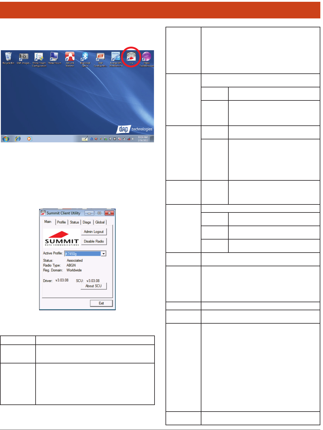
To launch, double-tap the scu icon at the top of the screen:
6.1.1 Main Window
e Main window provides an overview of the current wireless network
connection conguration (Active Prole), a snapshot of connection in-
formation as well as access to administrator functions (Admin Login/
Logout - administrator use only), and additional information regarding
SCU (About SCU).
e Main window displays the following properties and options:
6.0 Summit Radio
Element Description
Admin
Login/
Logout
Administrator use only.
Enable
Radio/
Disable
Radio
When the radio is enabled, select this button (which displays
Disable Radio) to disable it. When the radio is disabled, select
the same button (which now displays Enable Radio) to enable it.
Note: When the radio is enabled, it attempts to make and/
or maintains a connection to an access point. When a
radio is disabled, its power remains on but it does not
attempt to make a connection to an access point.
Active
Prole
Displays the name of the active. Use the drop-down menu to
select a dierent prole.
Note: If irdPartyCong is selected (and aer the device
goes through a power cycle), WZC (Windows Zero
Conguration) or another application is used to con-
gure the SSID, Auth Type, EAP Type, and Encryp-
tion settings. See “irdPartyCong” for more infor-
mation.
Status
Indicates the current status of the Summit radio. Connection
status options include:
Down e radio is not recognized by Summit soware
and thus is not associated nor authenticated.
Disabled e radio is disabled. To enable the radio, tap
Enable Radio located on the SCU Main window.
When the radio is disabled, it does not attempt
to make a connection to an access point.
Status
(cont’d)
Not
Associated
e radio has not established a connection to
an access point.
Associated e radio has established a connection to an
access point but is not EAP authenticated. e
radio can not communicate unless it is associated
and EAP authenticated.
Note: If the Encryption type is set to WEP or
Open (None), it can communicate (send
data) while in the Associated state.
<EAP type>
Authenti-
cated
e radio has established a connection to an
access point and has completed EAP authenti-
cation successfully. In this state, the radio can
communicate (send data).
Radio Type Indicates the type of radio installed in the device. For example:
BG Indicates a Summit 802.11g radio which sup-
ports 802.11b and 802.11g.
ABG Indicates a Summit 802.11a/g radio which sup-
ports 802.11a , 802.11b, and 802.11g.
N Indicates Summit 802.11n radio which sup-
ports 802.11a, 802.11b, 802.11g, and 802.11n.
Reg.
Domain
Indicates the regulatory domain(s) for which the radio is
congured, including FCC, ETSI, TELEC, and KCC.
Auto Prole Auto prole enables you to activate or deactivate automatic
prole selection. Tap List and use the dialog box to select a
created prole.
Note: ere is a limit of 19 proles in the Auto Prole list.
Note: Auto Prole is only available on Windows CE and
Windows Mobile operating systems.
Driver Indicates the current version of the device driver.
SCU Indicates the SCU version currently running on the device.
Displays only if space permits.
Import/
Export
Displays only if the radio is programmed to allow import/ex-
port functions if you are logged in as an administrator.
Tap Import/Export and use the dialog box to do one of the
following:
• Export global settings, all standard SCU proles, and the spe-
cial irdPartyCong prole from the SCU area of a device’s
registry to a le that can be transferred to another device.
• Importglobalsettings,allstandardSCUproles,andthespe-
cial irdPartyCong prole from a le (created using the
Export facility) to the SCU area of a device’s registry to enable
SCU to use the information.
Note: When importing information, select Add to existing to
merge new information with current registry informa-
tion. Select Replace to overwrite the current registry
information with the newly-imported information.
About SCU Tap About SCU to view SCU information including driver
and the SCU version.
97
6.0 Summit Radio
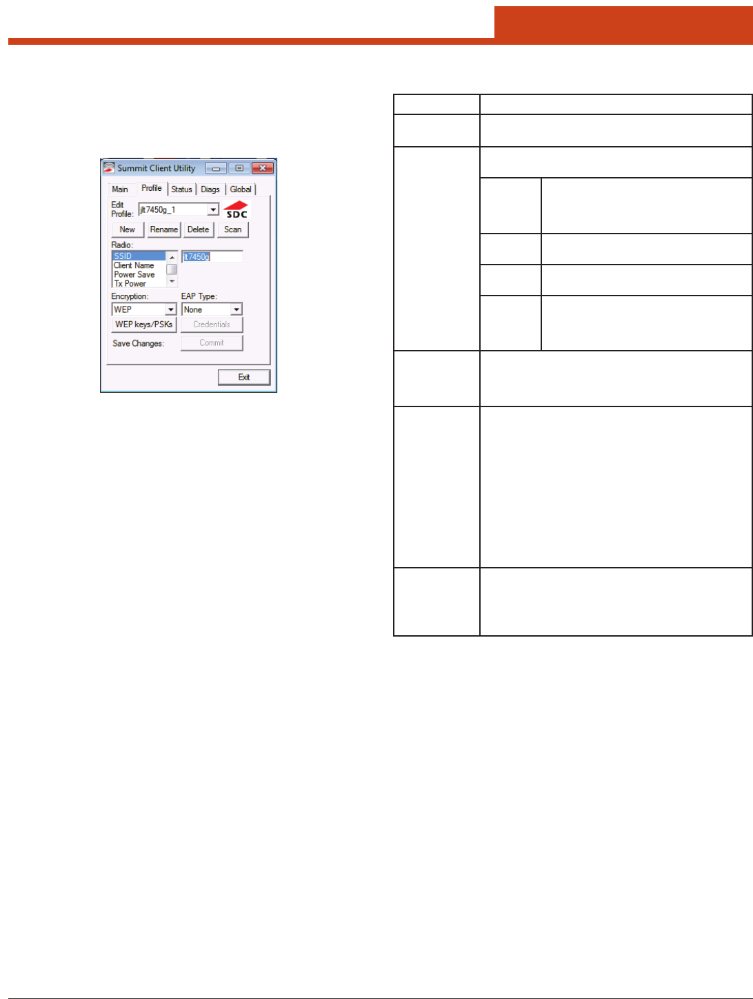
6.1.2 Prole Window
Prole settings are radio and security settings that are stored in the reg-
istry as part of a conguration prole. When a prole is selected as the
active prole on the Main window, the settings for that prole become
active.
Notes: When the irdPartyCong prole is selected, a power cycle
must be performed. See “irdPartyCong” for more informa-
tion.
If the Default prole is not modied, it does not specify an
SSID, an EAP type, or a data encryption method. As a result,
if the Default is the active prole, then the radio associates
only to an AP that broadcasts its SSID and requires no EAP
type and no encryption.
From the Prole window, an administrator can:
• Deneupto20proles,inadditiontothespecialirdPartyCong
prole.
• Changeprolesettings.
• DeleteanyproleexceptthespecialirdPartyCongandtheactive
prole.
Prole changes are not saved to the prole until you tap Commit.
Element Description
Edit Prole Use the drop-down menu to select the prole to be viewed
or edited. Only an administrator can edit a prole.
Actions Actions included New, Rename, Delete, and Scan. New,
Rename, and Delete are only available to an administrator.
New Create a new prole with default settings.
Assign a unique name (a string of up to 32
characters). Edit prole settings using other
Prole window selections.
Rename Change the prole name to one that is not as-
signed to another prole.
Delete Delete a non-active prole. You cannot delete
an active prole.
Scan Tap to view a list of APs that are broadcasting
SSIDs;selectanSSIDandcreateaproleforit.
See “Using Scan to Create a Prole” for more
information.
Radio Select a radio attribute from the list on the le to view its
value or setting in the box on the right. Only an administra-
tor can edit these values or settings. See “Radio Settings” for
more information.
Security Values for the two primary security attributes, EAP type and
encryption type, are displayed in separate drop-down lists
with the current values highlighted. Only an administrator
can edit these security settings. See “Security Settings” for
more information.
• Encryption - When the administrator selects an encryption
type that requires the denition of WEP keys or a pre-shared
key (PSK), the WEP keys/PSKs button becomes active. Tap
WEP keys/PSKs to dene WEP keys or a PSK.
• EAP Type - When the administrator selects an EAP type, the
Credentials button becomes active. Tap Credentials to dene
authentication credentials for the selected EAP type.
Save Changes To save changes for the selected prole, you must tap Com-
mit. If you make changes without tapping Commit and
attempt to move to a dierent SCU window, a warning mes-
sage displays and provides the option of saving your changes
before you leave the Prole window.

98
6.0 Summit Radio
6.1.2.1 Radio Settings
Element Description
SSID Use the drop-down menu to select the prole to be viewed
or edited. Only an administrator can edit a prole.
Client Name Actions included New, Rename, Delete, and Scan. New,
Rename, and Delete are only available to an administrator.
New Create a new prole with default settings.
Assign a unique name (a string of up to 32
characters). Edit prole settings using other
Prole window selections.
Rename Change the prole name to one that is not as-
signed to another prole.
Delete Delete a non-active prole. You cannot delete
an active prole.
Scan Tap to view a list of APs that are broadcasting
SSIDs;selectanSSIDandcreateaproleforit.
See “Using Scan to Create a Prole” for more
information.
Power Save Select a radio attribute from the list on the le to view its
value or setting in the box on the right. Only an administra-
tor can edit these values or settings. See “Radio Settings” for
more information.
Tx Power Values for the two primary security attributes, EAP type and
encryption type, are displayed in separate drop-down lists
with the current values highlighted. Only an administrator
can edit these security settings. See “Security Settings” for
more information.
• Encryption - When the administrator selects an encryption
type that requires the denition of WEP keys or a pre-shared
key (PSK), the WEP keys/PSKs button becomes active. Tap
WEP keys/PSKs to dene WEP keys or a PSK.
• EAP Type - When the administrator selects an EAP type, the
Credentials button becomes active. Tap Credentials to dene
authentication credentials for the selected EAP type.
Bit Rate To save changes for the selected prole, you must tap Com-
mit. If you make changes without tapping Commit and
attempt to move to a dierent SCU window, a warning mes-
sage displays and provides the option of saving your changes
before you leave the Prole window.
Radio Mode Use of 802.11a, 802.11g, 802.11b, and 802.11n frequencies and
data rates when interacting with AP, or use of ad hoc mode
to associate to a client radio instead of an AP. When SCU
operates with a Summit 802.11g radio, an administrator can
select from among the following Radio Mode values:
• Value:
– B rates only - 1, 2, 5.5, and 11 Mbps
– G rates only - 6, 9, 12, 18, 24, 36, 48, and 54 Mbps
– BG rates full - All B and G rates
– BG Subset - 1, 2, 5.5, 6, 11, 24, 36, and 54 Mbps. is
should only be used with Cisco APs running IOS in au-
tonomous mode (without controllers). For Cisco APs that
are tied to controllers and for non-Cisco APs, Summit
recommends BG rates full.
– Ad Hoc - When selected, the Summit radio uses ad hoc
mode instead of infrastructure mode. In infrastructure
mode, the radio associates to an AP. In ad hoc mode, the
radio associates to another client radio that is in ad hoc
mode and has the same SSID and, if congured, static
WEP key.
• Default - BG rates full
Radio Mode
(cont’d)
When SCU operates with a Summit 802.11a/g radio, an
administrator can select from among the following Radio
Mode values:
• Value:
– B rates only - 1, 2, 5.5, and 11 Mbps
– G rates only - 6, 9, 12, 18, 24, 36, 48, and 54 Mbps
– BG rates full - All B and G rates
– A rates only - 6, 9, 12, 18, 24, 36, 48, and 54 Mbps (same as
G rates)
– ABG rates full - All A rates and all B and G rates, with A
rates (the .11a radio) preferred. See “Preferred Band for
802.11a/g Radio” for more information.
– BGA rates full - All B and G rates and all A rates, with
B and G rates (the .11g radio) preferred. See “Preferred
Band for 802.11a/g Radio” for more information.
– BG Subset - 1, 2, 5.5, 6, 11, 24, 36, and 54 Mbps. is
should only be used with Cisco APs running IOS in au-
tonomous mode (without controllers). For Cisco APs that
are tied to controllers and for non-Cisco APs, Summit
recommends BG rates full.
– Ad Hoc - When selected, the Summit radio uses ad hoc
mode instead of infrastructure mode. In infrastructure
mode, the radio associates to an AP. In ad hoc mode, the ra-
dio associates to another client radio that is in ad hoc mode
and has the same SSID and, if congured, static WEP key.
• Default - ABG rates full
Auth Type 802.11 authentication type, used when associating to AP.
• Value - Open, shared-key, or LEAP (Network-EAP)
• Default - Open
Note: For a Cisco explanation of 802.11 authentication us-
ing Open and Network-EAP, see:
http://www.cisco.com/en/US/products/hw/wire-
less/ps4570/products_configuration_exam-
ple09186a00801bd035.shtml. e Summit Client
Utility refers to Network-EAP as LEAP.
6.1.2.2 Preferred Band for 802.11a/g Radio
When the Radio Mode value is ABG rates full or BGA rates full, one
band (5 GHz for ABG or 2.4 GHz for BGA) is preferred over the other.
When trying to associate to an AP, the radio considers APs in the pre-
ferred band. If the radio is able to associate to one of these APs, then the
radio will not try to associate to an AP in the other band. e only time
that the radio attempts to associate to an AP in the non-preferred band
is when the radio is not associated and cannot associate in the preferred
band. When roaming, the radio considers only APs in the current band
(the band in which the radio is currently associated). When an admin-
istrator tries to create or edit a prole, SCU determines which radio is
operating in the device and populates the available radio mode values ac-
cording to the radio type. Suppose a prole created for an 802.11a/g card
is loaded on a device with an 802.11g card. If a radio mode value of A
rates only, ABG rates full, or BGA rates full was set in the prole,
then SCU displays a value of BG rates full. If the administrator does
not save any changes to the prole, then SCU leaves the prole, including
the radio mode, unchanged. If the administrator saves any changes to the
prole, then SCU saves the radio mode value as BG rates full.
6.1.2.3 Ad Hoc
If the administrator selects Ad Hoc for radio mode, then the Summit
radio uses ad hoc mode instead of infrastructure mode. In infrastruc-
ture mode, the radio associates to an AP. In ad hoc mode, the radio as-
sociates to another client radio that is in ad hoc mode and has the same
SSID and, if congured, static WEP key.
99
6.0 Summit Radio
6.1.2.4 Security Settings
EAP type - Extensible Authentication Protocol type used for 802.1X au-
thentication to AP.
Value - None, LEAP, EAP-FAST, PEAP-MSCHAP, PEAP-GTC, PEAP-
TLS, EAP-TLS, EAP-TTLS
Default - None
Credentials - Authentication credentials for the selected EAP type. See
6.1.2.6 EAP Credentials for more information.
Encryption - Type of encryption (and decryption) used to protect
transmitted data. See “Encryption - Cisco TKIP” and “Encryption -
WPA Migration Mode and WPA2 Mixed” for more information.
• Value:
– None - No encryption.
– WEP - WEP with up to four static keys(40-bit or 128-bit in ASCII
or hex) dened under WEP/PSK Keys.
– WEP EAP - WEP with key generated during EAP authentication.
– CKIP - WEP with up to four static keys(40-bit or 128-bit in ASCII
or hex) dened under WEP/PSK Keys, plus Cisco TKIP and/or
Cisco MIC, if congured on AP.
– CKIP EAP - WEP with key generated during EAP authentication,
plus Cisco TKIP and/or Cisco MIC, if congured on AP.
– WPA-PSK (WPA Personal) - TKIP with PSK (ASCII passphrase
or hex PSK) dened under WEP/PSK Keys.
– WPA-TKIP(WPA Enterprise) - TKIP with key generated during
EAP authentication.
– WPA CCKM(WPA Enterprise) - TKIP with key generated during
EAP authentication and with Cisco key management protocol for
fast reauthentication.
– WPA2-PSK with PSK (ASCII passphrase or hex PSK) dened un-
der WEP/PSK Keys.
– WPA2-AES (WPA2 Enterprise) - AES with key generated during
EAP authentication.
– WPA2 CCKM (WPA2 Enterprise) - AES with key generated dur-
ing EAP authentication and with Cisco key management protocol
for reauthentication.
Note: For ABGN radios, CKIP and CKIP EAP are unavail-
able. WEP and WEP EAP are the defaults.
• Default:None
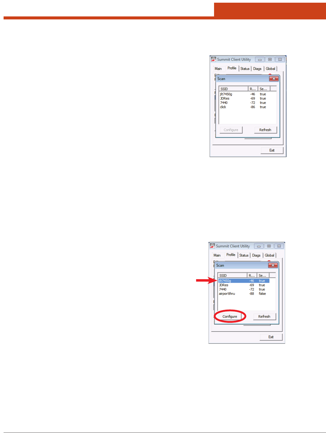
6.1.2.5 Using Scan to Create a Prole
When you tap Scan on the Prole window, SCU displays a list of APs that
are broadcasting their SSIDs:
e result shows an AP’s SSID, its received signal strength indication
(RSSI), and whether or not data encryption is in use (true or false). If
more than one AP appears, the list can be sorted by tapping on the col-
umn headers. If the scan nds more than one AP with the same SSID,
the list displays the AP with the strongest RSSI and the least security.
Every ve seconds, the Scan window updates the RSSI value for each of
the APs in the list. To scan for new APs and view an updated list, tap the
Refresh button.
An administrator in SCU can create a prole for any SSID in the list.
To do so, either double-tap the row for the SSID or tap the row and tap
Congure.
100
6.0 Summit Radio
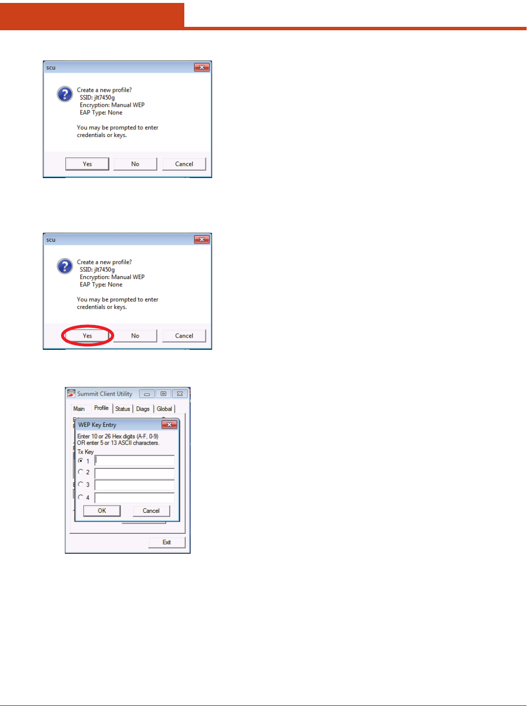
SCU will display a dialog box such as the one shown below:
If you tap the Yes button on the dialog box, then SCU will create a pro-
le for that SSID, with the prole name being the same as the SSID (or
the SSID with a sux such as “_1” if a prole with the SSID as its name
exists already).
If the AP is using WEP, then SCU will open a dialog box in which you
can specify WEP keys.
If the AP is using EAP, then SCU will open a dialog box in which you
can specify login credentials for the EAP type (which SCU assumes is
LEAP). Aer you enter information on a dialog box, you will return to
the SCU Prole window, where you can view and edit prole settings.
If you make any changes, then you must tap the Commit button to save
them.

101
6.0 Summit Radio
6.1.2.6 EAP Credentials
e 802.1X authentication types PEAP, EAP-TTLS, and EAP-TLS rely
upon information in digital certicates that are created by a certicate
authority, or CA. To enable a client device to validate (or authenticate)
the server used for PEAP, EAP-TTLS, or EAP-TLS authentication, you
must provision a root CA certicate and distribute it to that client. You
can store the CA certicate in a device’s Microso certicate store or in
a directory with a path that you specify as the value for Certs Path on the
SCU Global window. If you don’t specify a Certs Path value, then SCU
uses for the Certs Path value the path to the certs directory that is o
the SCU folder. For EAP-TLS you also must generate a user certicate for
eachclient;thatusercerticatemustbestoredintheMicrosocerticate
store on the client.
Instead of using digital certicates, EAP-FAST relies upon strong shared-
secret keys that are unique to users. ese secrets are called protected
EAP-Type User Password CA Cert Validate
Server
User MS Store Others
LEAP Username or Domain/
Username (up to 64
characters)
Password (up to 32
characters)
EAP-FAST Username or Domain/
Username (up to 64
characters)
Password (up to 32
characters)
•PACFilename(upto
32 characters)
•PACPassword(upto
32 characters)
PEAP-MSCHAP Username or Domain/
Username (up to 64
characters)
Password (up to 32
characters)
Filename (up to 32 char-
acters)
See Note on CA Cert Field
See Note on Validate
Server Checkbox
See Note on Use
MS store Checkbox
PEAP-TGC Username or Domain/
Username (up to 64
characters)
Password (up to 32
characters)
Filename (up to 32 char-
acters)
See Note on CA Cert Field
See Note on Validate
Server Checkbox
See Note on Use
MS store Checkbox
PEAP-TLS Username or Domain/
Username (up to 64
characters)
Password (up to 32
characters)
Filename (up to 32 char-
acters)
See Note on CA Cert Field
See Note on Validate
Server Checkbox
See Note on Use
MS store Checkbox
EAP-TTLS Username or Domain/
Username (up to 64
characters)
Password (up to 32
characters)
Filename (up to 32 char-
acters)
See Note on CA Cert Field
See Note on Validate
Server Checkbox
See Note on Use
MS store Checkbox
EAP-TLS Username or Domain/
Username (up to 64
characters)
Filename (up to 32 char-
acters)
See Note on CA Cert Field
See Note on Validate
Server Checkbox
See Note on Use
MS store Checkbox
User Cert
See Note on User Cert
access credentials (PACs) and can be created automatically or manually.
With automatic or in-band provisioning, the PAC is created and distrib-
uted to the client device in one operation. With manual or out-of-band
provisioning, the PAC is created in one step and then must be distributed
to the client device separately. SCU supports PACs created automatically
or manually. When you create a PAC manually, you must load it to the
directory identied by the Certs Path global setting. Be sure that the PAC
le does not have read-only permissions set, or SCU will not be able to
use the PAC.
ere are no default values for credentials. If the credentials are not speci-
ed in the prole then, when the radio tries to associate using that prole,
Summit soware will display a dialog box that prompts the user to enter
the credentials. Summit soware will populate the dialog box with the
username and password supplied for the previous EAP authentication.
Note on CA Cert Field: is is the lename of the root certicate authority
digital certicate. Leave this blank if the Use MS Store checkbox is checked.
Note on Validate Server Checkbox: Check this if using a CA certicate
to validate an authentication server. When this is checked, a certicate lename
must be entered in the CA Cert eld or check the Use MS store checkbox.
Note: Summit strongly recommends the use of server validation with PEAP-
GTC.
Note on Use MS Store Checkbox: Check this if the Microso certicate
store should be used for a CA certicate. is is applicable only when Validate
Server is checked.
Note on User Cert: Tap the “...” button to select a user (or station) certicate
fromtheMicrosocerticatestore.Donotenteralename;theusercerticate
must reside in the Microso certicate store. When browsing for a certicate, the
pop-up box displays Issued By and Issued To.
Of the seven EAP types supported by SCU, all but EAP-FAST and LEAP rely
upon information in digital certicates that are created by a certicate authority
(CA). To enable a station device to authenticate the server, provide a root CA
certicate and distribute it to that station. e CA certicate can be stored in
Notes for EAP Credentials
a unit’s Microso certicate store or in a specied directory (see Certs Path for
additional information regarding a specied directory).
Note: For EAP-TLS, the user must also generate a user certicate for each
station. e user certicate must be stored in the Microso certicate
store on the station.
EAP-FAST relies upon strong shared-secret keys that are unique to users (rath-
er than digital certicates). ese keys are called protected access credentials
(PACs) and can be created automatically or manually. With automatic or in-
band provisioning, the PAC is created and distributed to the station device in
one operation. With manual or out-of-band provisioning, the PAC is created in
one step and must then be distributed to the station device separately.
SCU supports PACs created automatically or manually. When the user creates a
PAC manually, it must be loaded into the directory identied by the Certs Path
global setting. Be sure that the PAC le does not have read-only permissions set,
or SCU will not be able to use the PAC.
Note: If the user enters a PAC lename in the SCU eld, manual provisioning is
used. If the user omits the PAC lename, automatic provisioning is used.
102
6.0 Summit Radio
Element Description
Prole e active prole.
Status
Indicates the current status of the Summit radio. Potential
values include:
Down e radio is not recognized by Summit
soware, possibly because the radio is not
installed properly.
Disabled e radio has been disabled because Disable
Radio on the SCU Main window has been
tapped. To enable the radio, tap Enable Radio
on the SCU Main window.
Not As-
sociated
e radio is not associated to an AP, possibly
because no AP for the active prole is in range.
Associ-
ated
e radio is associated to an AP. If the radio is
not sending or receiving from the AP, then:
• IfWEP isbeingused,then oneof the WEP
keys in the active prole is invalid.
• If WPA-PSK or WPA2-PSK is being used,
then the PSK or password is invalid.
• IfWPA-EnterpriseorWPA2-Enterpriseisbe-
ing used, then the radio did not complete EAP
authentication successfully.
<EAP
type>
Authenti-
cated
e radio is associated to an AP and has
completed EAP authentication successfully.
Device
Information
• Client name, if dened in active prole
• IP address
• MAC address
6.1.2.7 Encryption
6.1.2.7.1 Cisco TKIP
If the active prole has an Encryption setting of CKIP or CKIP EAP, then
the Summit radio will associate or roam successfully to an AP is cong-
ured with:
• eSSIDandotherRFsettingsoftheactiveprole
• eauthenticationmethodoftheactiveprole
• ForWEP,thestaticWEPkeysoftheactiveprole
• Anyofthefollowingencryptionsettings:
– WEP only (no CKIP or CMIC)
– WEP with CKIP
– WEP with CMIC
– WEP with CKIP and CMIC
6.1.2.7.2 WPA Migration Mode and WPA2 Mixed Mode
Summit radios support two special AP settings: WPA Migration Mode
and WPA2 Mixed Mode. WPA Migration Mode is a setting on Cisco
APs that enables both WPA and non-WPA clients to associate to an AP
using the same SSID, provided that the AP is congured for Migration
Mode (WPA optional with TKIP+WEP128 or TKIP+WEP40 cipher). In
other words, WPA Migration Mode means WPA key management with
TKIP for the pairwise cipher and TKIP, 128-bit WEP, or 40-bit WEP for
the group cipher. When WPA Migration Mode in use, you can select
WPA TKIP or WEP EAP for your Summit radio encryption type.
WPA2 Mixed Mode operation enables both WPA and WPA2 clients to
associate to an AP using the same SSID. WPA2 Mixed Mode is dened
by the Wi-Fi Alliance, and support for the feature is a part of Wi-Fi
certication testing. When WPA2 Mixed Mode is congured, the AP
advertises the encryption ciphers (TKIP, CCMP, other) that are avail-
able for use, and the client selects the encryption cipher it wants to use.
In other words, WPA Mixed Mode means WPA key management with
AES for the pairwise cipher and AES or TKIP for the group cipher.
When WPA2 Mixed Mode in use, you can select WPA2 AES or WPA
TKIP for your Summit radio encryption type.
6.1.2.8 ThirdPartyCong
If the prole named ThirdPartyCong is selected as the active pro-
le, then SCU works in tandem with WZC or another third-party appli-
cation for conguration of all radio and security settings for the radio.
e third-party application must be used to dene the SSID, Auth Type,
EAP Type, and Encryption settings. SCU can be used to dene the Cli-
ent Name, Power Save, Tx Power, Bit Rate, and Radio Mode settings.
ose SCU prole settings, all SCU global settings, and the third-party
application settings are applied to the radio when irdPartyCong is
selected as the active prole and a power cycle is performed.
On some devices that run Pocket PC or Windows Mobile, the radio will
not associate if WPA with pre-shared keys, or WPA-PSK, is used with
WZC. If that is the case for your device, then to use WPA-PSK you must
use an SCU prole other than irdPartyCong.
6.1.2.9 EAP-FAST
e 802.1X authentication types PEAP and EAP-FAST use a client-
server security architecture that encrypts EAP transactions within a
TLS tunnel. PEAP relies on the provisioning and distribution of a digital
certicate for the authentication server. With EAP-FAST, tunnel estab-
lishment is based upon strong shared-secret keys that are unique to us-
ers. ese secrets are called protected access credentials (PACs) and can
be created automatically or manually. With automatic or in-band pro-
visioning, the PAC is created and distributed to the client device in one
operation. With manual or out-of-band provisioning, the PAC is created
in one step and then must be distributed to the client device separately.
SCU supports PACs created automatically or manually. When you cre-
ate a PAC manually, you must load it to the certs directory on the device
that runs SCU. Be sure that the PAC le does not have read-only permis-
sions set, or SCU will not be able to use the PAC.
Note: If you enter a PAC lename in the SCU eld, manual provision-
ing is used. If you omit the PAC lename, automatic provision-
ing is used.
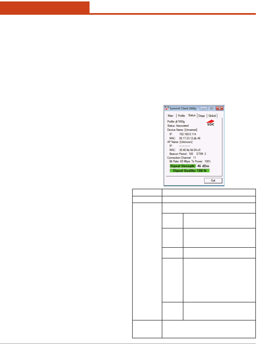
6.1.3 Status Window
e Status window provides status information on the radio. A sample
Status window is shown below:
103
6.0 Summit Radio
AP
Information
• Name
• IP address
• MAC address
• Beacon period: Amount of time between AP beacons in Kilo-
microseconds, where one Ksec equals 1,024 microseconds
• DTIM interval: A multiple of the beacon period that species
how oen the beacon contains a delivery trac indication
message(DTIM), which tells power-save client devices that a
packet is waiting for them (e.g. a DTIM interval of 3 means
that every third beacon contains a DTIM)
Connection
Information
• Channel
• Transmit power
• Data (bit) rate
• Signal strength (RSSI), displayed graphically and in dBm
– A green color indicates that the RSSI for the current AP
is stronger than -70 dBm, which means that the Summit
radio should operate consistently at 54 Mbps
– A yellow color indicates that the RSSI for the current AP
is stronger than -90 dBm but not stronger than -70 dBm,
which means that a Summit radio will operate at 802.11g
or 802.11a data rates that are less than 54 Mbps
– A red color indicates that the RSSI for the current AP(to
which the radio is associated) is -90 dBm or weaker,
which means that a Summit 802.11b/g radio will operate
at 802.11b data rates only
• Signal quality (%), a measure of the clarity of the signal, dis-
played graphically and in dBm -- is value will be lower
with a irdPartyCong prole (under Windows Zero Con-
g) than with a standard prole
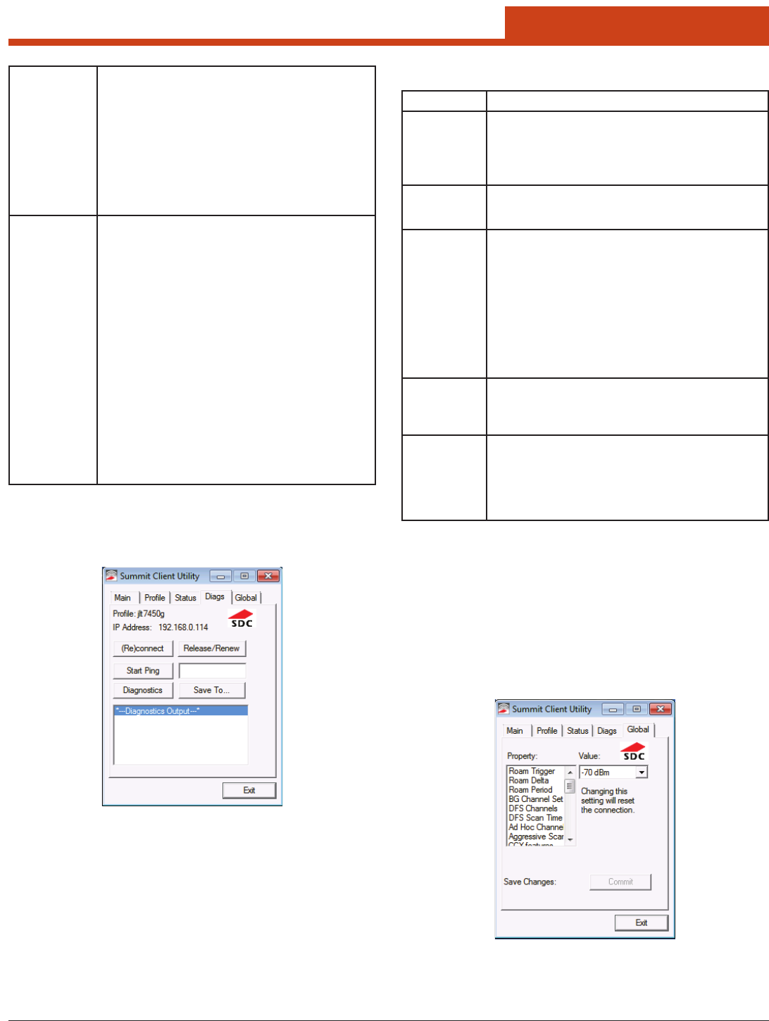
6.1.4 Diags Window
A sample Diags, or troubleshooting, window is shown below: Note: When a ping initiated from the Diags window is active, the Sta-
tus window displays a ping indicator consisting of two lights
thatashgreen(forasuccessfulping)orred(foranunsuccess-
ful ping).
Element Description
(Re)connect Initiate a reconnect of the radio: Disable and enable the
radio, apply (or reapply) the current prole, attempt to as-
sociate to the wireless LAN, and attempt to authenticate to
the wireless LAN. SCU logs all activity in the output area at
the bottom of the Diags window.
Release /
Renew
Obtain a new IP address through DHCP release/renew. SCU
logs all activity in the output area at the bottom of the Diags
window.
Start Ping /
Stop Ping
Start a continuous ping to the address in the edit box next to
the button. Once the button is tapped, its name and function
changes to Stop Ping. Pings continue until you tap Stop
Ping, move to a dierent SCU window (other than Diags or
Status), exit SCU, or remove the radio.
Note: If your device has both a Summit radio and another
network adapter active, then pings may go out over
the non-Summit network adapter.
Note: e access point’s IP address is the default for a ping
although any valid IP address can be manually en-
tered.
Diagnostics Attempt to (re)connect to an access point and provide a more
thorough dump of data than is obtained with (Re)connect.
e dump includes radio state, prole settings, global set-
tings, and a BSSID list of access points in the area.
Save To... Indicate where you want to save the diagnostics le.
Tap Save To... to open the Save As window. From here, you
can change the SDC diagnostics le name, the folder in which
SCU saves the le, the format in which the le is saved (the
le type), and the location of the saved le (Main memory or
System).
6.1.5 Global Window
Global settings include radio and security settings that apply to all proles
and settings that apply to SCU itself. An administrator can dene and
change most global settings on the Global window in SCU:
Here are the functions available on the Diags window:

104
6.0 Summit Radio
Terms Denitions
Roam Trigger When moving average RSSI from current AP is weaker than
Roam Trigger, radio does a roam scan where it probes for an
AP with a signal that is at least Roam Delta dBm stronger.
• Value:-50,-55,-60,-65,-70,-75,-80,-85,-90,orCustom(see
note on Custom below the list)
• Default:-70
Roam Delta When Roam Trigger is met, second AP’s signal strength (RSSI)
must be Roam Delta dBm stronger than moving average RSSI
for current AP before radio will attempt to roam to second AP.
• Value:5,10,15,20,25,30,35,orCustom(seenoteonCustom
below the list)
• Default:10
Roam Period Aer association or roam scan (with no roam), radio will col-
lect RSSI scan data for Roam Period seconds before consider-
ing roaming.
• Value:5,10,15,20,25,30,35,40,45,50,55,60,orCustom
(see note on Custom below the list)
• Default:10
BG Channel
Set
Denes the 2.4 GHz channels to be scanned when the radio is
contemplating a roam and to determine what APs are available:
• Value: Full (all channels); 1,6,11 (the mostcommonly used
2.4GHzchannels);1,7,13(forETSIandTELECradiosonly);
or Custom (see note on Custom below the list)
• Default:Full
DFS Channels Support for 5 GHz (802.11a) channels where support for
dynamic frequency selection (DFS) is required.
• Value:On,O,Optimized
Note: When set to Optimized and scanning for the rst
time, the radio scans all active channels and all
available DFS channels. From this scan, the radio
creates and maintains a list of up to three DFS chan-
nels where beacons were detected. During subse-
quent scans, the radio still scans all active channels
but only scans the DFS channels listed from the rst
scan (where beacons were detected).
When the radio loses or resets the connection, the radio re-
turns to scanning all available DFS channels as it did when
scanning for the rst time aer being set to Optimized. From
this scan, the radio again creates a list of DFS channels where
beacons were detected.
Note: e Optimized setting is not supported in the MS-
D30AG and SSD30AG radios. If DFS Channels is
set to Optimized directly in the registry, the setting
will function as On (versus Optimized).
• Default:Full
DFS Scan
Time
Because passive scanning consumes a longer period of time,
this feature enables you to determine the dwell (listen) time
when passively scanning on a DFS channel.
• Value:Anumberbetween20-500milliseconds(ms)
• Default:120ms
Note: When decreasing the scan time (to a value lower than
the default) for DFS channels, corresponding changes
in the infrastructure’s beacon period are recommend-
ed. For optimal performance and reliability, Summit
recommends a dwell time that is 1.5 times that of the
beacon period. For example, if the DFS scan time is
set to 30 ms, the beacon period should be adjusted to
20 ms.
Note: If you adjust this parameter directly in the registry, and
congure it to a number outside of the 20-500 ms range,
the setting value will return to the default (120 ms).
Ad Hoc Chan-
nel
e channel to be used for an ad hoc connection if the active
prole has a Radio Mode value of “Ad Hoc”
• Value:Oneofthe2.4GHzchannels(1-14)orUNII-1channels
(36, 40, 44, 48) -- If you select a channel that is not supported
by your radio, then SCU uses the default value for this setting.
• Default:1
Aggressive
Scan
When this setting is On and the current connection to an AP
becomes tenuous, the radio scans for available APs more aggres-
sively. Aggressive scanning complements and works in conjunc-
tion with the standard scanning that is congured through the
Roam Trigger, Roam Delta, and Roam Period settings. Summit
recommends that the Aggressive Scan global setting be On un-
less there is signicant co-channel interference because of over-
lapping coverage from APs that are on the same channel.
• Value:OnorO
• Default:On
CCX Support Use of Cisco information element (IE) and CCX version num-
ber;supportforCCXfeatures.
• Value:
– Full:UseCiscoIEandCCXversionnumber;supportall
CCX features
– Optimized: UseCisco IE andCCX versionnumber; sup-
port all CCX features except AP-assisted roaming, AP-spec-
ied maximum transmit power, and radio management
– O: Do not use Cisco IE and CCX version number
• Default:Optimized
Note: For 30AG (MSD30AG and SSD30AG) radio modules,
this parameter is disabled. e default is Optimized.
WMM Use of Wi-Fi Multimedia Extensions, also known as WMM.
• Value:On,O
• Default:O
Note: For ABGN radio modules, this parameter is disabled.
Auth Server Type of authentication server being used for EAP.
• Value:
– Type 1: Cisco Secure ACS or another server that uses
PEAPv1 for PEAP with EAP-MSCHAPV2 (PEAP-MSC-
HAP)
– Type 2: A dierent authentication server, such as Juniper
Networks Steel Belted RADIUS, that uses PEAPv0 for
PEAP-MSCHAP
• Default:Type1
TTLS Inner
Method
Authentication method used within secure tunnel created by
EAP-TTLS:
• Value:
– Auto-EAP: Any available EAP method
– MSCHAPV2
– MSCHAP
– PAP
– CHAP
– EAP-MSCHAPV2
• Default:Auto-EAP
PMK Caching When WPA2 is in use, type of Pairwise Master Key (PMK)
caching to use—See the section on PMK Caching.
• Value:StandardorOPMK
• Default:Standard
Note: When switching from Standard to OPMK, you must
initiate a suspend resume of the device. Only tapping
Commit does not cause the change to take eect.
e following radio global settings, which apply to all conguration pro-
les, can be changed in SCU:

105
6.0 Summit Radio
Frag Thresh If packet size (in bytes) exceeds threshold, then packet is frag-
mented
• Value:Anintegerfrom256to2346
• Default:2346
Note: For 30AG (MSD30AG and SSD30AG) radio modules,
this parameter is disabled.
RTS Thresh Packet size above which RTS/CTS is required on link
• Value:Anintegerfrom0to2347
• Default:2347
Note: For 30AG (MSD30AG and SSD30AG) radio modules,
this parameter is disabled.
RX Diversity How to handle antenna diversity when receiving data from AP
• Value:
– On-Start on Main: On startup use main antenna
– On-Start on Aux: On startup, use auxiliary antenna
– Main only: Use main antenna only
– Aux only: Use auxiliary antenna only
Note: Summit does not support the AUX antenna as a
single-antenna solution.
• Default:On-StartonMain
Note: For ABGN and 30AG (MSD30AG and SSD30AG) ra-
dio modules, this parameter is disabled.
TX Diversity How to handle antenna diversity when transmitting data to AP
• Value:
– Main only: Use main antenna only
– Aux only: Use auxiliary antenna only
Note: Summit does not support the AUX antenna as a
single-antenna solution.
– On: Use diversity
• Default:On
Note: For 30AG (MSD30AG and SSD30AG) radio modules,
this parameter is disabled.
LED UseofLED;availableonlywithMCF10G
• Value:On,O
• Default:O
If SCU displays a value of “Custom” for a global setting, then the op-
erating system registry has been edited to include a value that is not
available for selection on the Global window. Selecting Custom has no
real eect. If SCU displays a value other than Custom and you select the
value of Custom and tap Commit, then SCU reverts to the value that it
displayed before you selected Custom.
e following SCU global settings, which apply to SCU and other Sum-
mit applications, can be changed in SCU:
Hide Pass-
words
If this is On, then SCU as well as EAP authentication dialog
boxes mask passwords and other sensitive information, such
as WEP keys.
• Value:On,O
• Default:O
Admin Pass-
word
Password that must be specied when Admin Login button
pressed.
• Value:Astringofupto64characters
• Default:SUMMIT
Certs Path Directory where certicate(s) for EAP authentication and PAC
les are housed.
• Value:Avaliddirectorypathofupto64characters
• Default:Dependsondevice
Auth Time-
out
Species the number of seconds that Summit soware will
wait for an EAP authentication request to succeed or fail. If
authentication credentials are specied in the active prole
and the authentication times out, then association will fail. If
authentication credentials are not specied in the active pro-
le and the authentication times out, then the user will be re-
prompted to enter authentication credentials.
• Value:Anintegerfrom3to60
• Default:8
Ping Payload
Amount of data in bytes to be transmitted on a ping.
• Value:32,64,128,256,512,1024
• Default:32
Ping Timeout
ms
Amount of time in milliseconds that transpires without a re-
sponse before ping request is considered a failure.
• Value:Anintegerfrom1to30000
• Default:5000
Ping Delay
ms
Amount of time in milliseconds between successive ping
requests
• Value:Anintegerfrom0to7200000
• Default:1000
When you change global settings and tap Commit, the changes take ef-
fectimmediately.eonlyexceptionistheWMMsetting;ifyouchange
it, you must do a power cycle or suspend/resume on the device to cause
the change to take eect. SCU provides you with a warning about the re-
quired power cycle.) To cause global settings changes to take eect with-
out a power cycle, Summit soware may have to reset and re-establish
the WLAN connection between the Summit radio and the AP.
If you make changes without tapping Commit and attempt to move to a
dierent SCU window, SCU will display a warning message and give you
the option of saving your changes before you leave the Global window.
A few global settings can be dened or set only through a separate util-
ity such as the Summit Manufacturing Utility, which Summit makes
available only to device manufacturers and not to their customers.

106
6.0 Summit Radio
6.1.6 PMK Caching
PMK caching is an alternative to CCKM supported with WPA2. e goal
of PMK caching is to speed up roaming between APs by accomplishing
802.1X reauthentications without communicating with the authentica-
tion server. When a client does an initial authentication to the WLAN
infrastructure, both sides derive the information needed for reauthentica-
tions.
If there are no controllers, then standard PMK caching is used, and reau-
thentication information is cached only on the initial AP. When the client
tries to reauthenticate to that AP, the client and the AP use the cached
information to do the four-way handshake to exchange keys. If there are
controllers, then opportunistic PMK caching is used, and reauthentica-
tion information is cached on the controllers. When the client tries to re-
authenticate, the client and the controller behind the AP use the cached
information to do the four-way handshake to exchange keys.
Use the PMK Caching global setting to congure the type of PMK cach-
ing supported by your infrastructure. If the Summit radio is congured
for one type of PMK caching and the infrastructure supports the other
type, then PMK caching will not work, and every roam will require a full
802.1X authentication that requires interaction with an authentication
server.
If the active prole has an Encryption setting of WPA2 CCKM, then the
Summit radio ignores the PMK Caching global setting and attempts to
use CCKM.

107
7.0 Bluetooth
At the top of the Main Window are Service Buttons. Aer you search for
the services supported by a remote device, the supported services of the
selected device will be highlighted.
Local Device — Basic Operations:
• Hoveryourmouseovertheredballtodisplaythelocaldevice’sBlue-
tooth name and address.
• ClickontheredballtostartorstopsearchingforBluetoothdevices
in range.
• Right-clickontheredballtodisplayapop-upmenuofrelatedop-
erations (e.g., General Inquiry, My Services, Security, etc.).
Remote Devices — Icon Meanings
• White—Idle.enormalstateofthedevice.
• Yellow—Selected.Youhaveselectedthedevice.
• Green—Connected.edeviceisconnectedtoyourlocaldevice.
Remote Devices — Operations
• Single-clicktoselect.
• Double-clicktosearchfortheservicessupportedbythedevice.
• Right-clicktodisplayapop-upmenuofrelatedoperations(e.g.,Re-
fresh Devices, Pair Devices, Connect, etc.).
Services — Icon Meanings
• White—Idle.enormalstate.
• Yellow—Available.eserviceisavailableontheselecteddevice.
• Green—Connected.eserviceisactiveinaconnectionwiththe
remote device.
Services — Operations
• Hoveryourmouseovertheserviceicontodisplaythenameofthe
service.
• Single-clickontheserviceicontoconnect.
• Right-clickontheserviceicontodisplayapop-upmenuofrelated
operations.
7.1 Introduction
BlueSoleil is a Windows-based soware from IVT that allows your Blue-
tooth® enabled desktop or notebook computer to wirelessly connect to
other Bluetooth enabled devices. BlueSoleil allows MS Windows users
to wirelessly access a wide variety of Bluetooth enabled digital devices,
such as cameras, mobile phones, headsets, printers, and GPS receivers.
You can also form networks and exchange data with other Bluetooth
enabled computers or PDAs.
7.1.1 Bluetooth Functions
In order to connect and share services via Bluetooth wireless technol-
ogy, two devices must support the same Bluetooth Prole(s) as well as
opposite device roles (i.e., one must be the server, and the other must be
the client).
Bluetooth enabled devices oen support multiple proles, and if in-
volved in multiple connections, can perform dierent device roles si-
multaneously.
BlueSoleil supports the following Bluetooth functions (Proles) in the
following device roles:
Notes:
• OnlyoneHeadsetorAVHeadphoneconnectioncanexistata
time, since since there is only one virtual Bluetooth audio de-
vice.
• eHeadsetandAVHeadphoneProlesdonotworkonWin-
dows 98SE or Windows Me.
7.1.2 Main Window
By default, BlueSoleil starts with the Main Window open. Use the Main
Window to perform your primary connection operations. e Main
Window displays the local device (red ball) as well as the remote devices
detected in range.
Note: For more complete information about the Main Window (in-
cluding the icon meanings) as well as information about the
Service Window and BlueSoleil menus, please refer to 7.4.
Dierent icons distinguish dierent types of remote devices.
Bluetooth
Functions
(Proles)
Client Server
AV Headphone* √ √
Basic Image Prole √ √
Dial-Up Networking √
Fax √
File Transfer √ √
Headset* √ √
Human Interface Device √
LAN Access √ √
Object Push √ √
Personal Area Networking √ √
Printer √
Serial Port √ √
Synchronization √ √
7.0 BlueTooth

108
7.0 Bluetooth
7.2 Basic Operations
7.2.1 Start BlueSoleil
1. Click on the BlueSoleil icon on your desktop, or go to:
Start | Programs | IVT BlueSoleil | BlueSoleil
2. e rst time BlueSoleil is launched, the Welcome to Bluetooth
screen will appear. Assign your Windows system a name and device
type, to be shown to other Bluetooth enabled devices. In most cases,
you should leave the security setting checked.
3. Click OK.
7.2.2 Search for Other Bluetooth En-
abled Devices
Before it can connect, your computer must rst detect other Bluetooth
enabled devices in range.
Initiate a Device Search
1. Make sure that the Bluetooth enabled device you wish to connect to
is turned on, with sucient battery power, and set in discoverable
mode. Have any necessary passkeys ready. If necessary, you may
also need to enable the service you want to use on the remote device.
Refer to the remote device’s user documentation for instructions.
If you haven’t done so already, you may also want to assign the de-
vice a Bluetooth name. Refer to the device’s user documentation for
instructions.
2. In the Main Window, click on the red ball to start the device search.
3. Alternatively, click:
My Bluetooth | My Device Inquiry
or
View | Refresh Devices
or
press F5
4. Aer a few seconds, an icon will appear around the center ball for
each Bluetooth enabled device detected within the radio range.
Note:
• eMainWindowcandisplayonlyeightdiscovereddevicesat
a time. If BlueSoleil discovered more than eight devices, use the
scroll bar to view the remaining devices discovered by BlueSoleil.
• To sort the devices by device name, device address, or device
type, click:
View | Arrange Devices
5. Wait several seconds until BlueSoleil reports the name of each device.
6. If the device you want is not listed, make sure that the device is
turned on and discoverable and try searching again. You have mul-
tiple options for starting another search:
• Ifyoustartanothersearchbydouble-clickingontheredballor
clicking —
My Bluetooth | My Device Inquiry
or
View | Refresh Devices
then the list of previously detected devices will not be cleared.
•IfyoustartanothersearchbypressingF5,thenthelistofprevi-
ously detected devices will be cleared.
7.2.3 Establish Connection
Note: ese are generic instructions for any type of Bluetooth en-
abled device. Refer to the instructions in 7.3 for specic de-
tails for the type of service you plan to use.
Normally, a connection is initiated from the client. Check the chart in
7.1.1 to verify which device role BlueSoleil supports for the service you
wish to use.
• Ontheserverside,starttheservice
• Ontheclientside,initiatetheconnection
7.2.3.1 Start the Service
If you would like to use your computer as a server in a Bluetooth con-
nection, you must rst start (enable) the appropriate service(s) on your
system.
1. To access the Service Window, click:
View | Service Window
2. If the icon for a service is highlighted (yellow), then the service has
already been started. If the icon is white, then you need to start the
service in order to use it. Right-click the icon. In the pop-up menu,
select Start Service. e icon should now be highlighted (yellow). Se-
rial Port icons will also report which COM port is assigned to them.
Note:
• IconswillappearonlyforBluetoothfunctions(Proles)which
BlueSoleil supports in the Server device role. See chart in 7.1.1
Bluetooth Functions.
• Dependingonyoursystem,multipleiconsforSerialCOMports
may appear.
3. Aer you have started the service in BlueSoleil, now you are ready
to initiate the connection from the remote device. For instructions,
refer to the user documentation for the remote device.
7.2.3.2 Initiate the Connection
If you would like to use your computer as a client in a Bluetooth connec-
tion, make sure that you have started (enabled) the service on the remote
device. Otherwise, BlueSoleil will not be able to discover the service and
connect to it. For instructions, refer to the device’s user documentation.
1. Return to the Main Window by clicking:
View | Main Window
2. Double-click on the icon for the device you wish to connect to. Blue-
Soleil will begin to search for information about which services the
device supports.
3. Aer the search, icons will be highlighted (yellow) at the top of the
BlueSoleil Main Window for services that are supported by the de-
vice. Verify that the service you want to use is supported.
4. Right-click on the device icon. In the pop-up menu, click Connect,
then select the service. BlueSoleil will start the connection. Depend-
ing on the security settings of each device, you may need to enter the
same passkey on each device in order to bond the two devices.
5. A screen may appear asking if you want to set up automatic connec-
tions. Click Yes or No.
6. If you are connecting to a phone, your phone may ask if you want to
109
7.0 Bluetooth
ask the BlueSoleil computer to your device list. Enter Yes and enter a
passkey.
7. When the devices have successfully connected, the device icon in
the Main Window will turn green, and a green line will appear be-
tween the red ball and the device icon. A red dot will travel along the
green line from the client to the server. A signal strength icon will
also appear next to the device icon.
e BlueSoleil icon in the task tray will also turn green to indicate an
active connection.
Note: A red check mark will appear next to the name of any device
that you have previously paired with your computer.
8. Depending on which services you are using, additional screens may
appear, and/or you may need to congure additional connection
settings (e.g., user name, password, COM port number, etc.). Refer
to the instructions in 7.3 for your specic service. Aer conguring
the appropriate connection settings, you should be ready to use your
application.
9. To end a connection, in the Main Window, right-click on the icon
for a connected device. In the pop-up menu, click Disconnect.
Note: You can only disconnect this way if your computer is acting
as a client device. If your computer is acting as a server device,
then you can disconnect in BlueSoleil by clicking:
View | Service Window
then right-clicking on the service icon. In the pop-up menu,
click Stop Service. Alternatively, you can disconnect from the
remote device.
7.2.4 Bluetooth Security
To modify your connection’s security settings, click:
My Bluetooth | Security
BlueSoleil oers three security levels:
• Low (Security Mode 1, Non-secure)
No security procedure is needed for connections.
• Medium (Security Mode 2, Service level enforced security)
Authentication or Authorization is requested when a specic service
is accessed by other Bluetooth enabled devices. If two devices are
connecting for the rst time, or if two devices do not have a trusted
relationship, then the same passkey must be provided on both sides
to complete the Authentication. is mode allows you to assign dif-
ferent access rights for each service supported by the server device.
• High (Security Mode 3, Link level enforced security)
If either of two devices is in Mode 3, Authentication is requested
whenever a link connection is initiated between two Bluetooth en-
abled devices. e passkey must be provided on both sides to com-
plete Authentication.
Note: In Security Mode 2, the user can add each authenticated de-
vice into a trusted device list to expedite future connections.
7.3 Getting Started
7.3.1 AV Headphone
e AV Headphone Prole enables use of a Bluetooth enabled head-
phone to listen to high-quality stereo music played on a computer.
Typical Usage
• ListentomusicusingaBluetoothenabledAVheadphone.
Step 1: Connect to the AV headphone, following the instructions in
7.2.3.
Step 2: Play music using media player soware on your computer.
Music will transmit wirelessly to the headphone.
7.3.2 Basic Imaging
e Basic Imaging Prole (BIP) enables users to receive pictures from
a Bluetooth enabled digital camera, mobile phone, or other compatible
device. It also enables remote control of shooting, display, and other
imaging functions.
Typical Usage
• Controlcameratotakepictures
• ReceivepicturessentfromBIP-enableddigitaldevices
Step 1: Connect to the camera, following the directions in Section
7.2.4. A Bluetooth Camera Controller will appear.
Step 2: Click the button to capture the image. e captured image
will be transmitted to your computer and displayed.
Receive Pictures
Step 1: Assign the directory where you would like to save image les
pushed from the client device. Click My Services | Properties.
Click on the Basic Image Push tab. In the Set the image direc-
tory eld, browse to select the le location. Click OK.
Step 2: Start the BIP service, following the directions in 7.2.3.
Step 3: Send pictures from the remote device. For instructions, refer
to the user documentation for the remote device.
7.3.3 Dial-up Networking
e Bluetooth Dial-up Networking (DUN) Prole enables users to wire-
lessly dial-up to the Internet through a Bluetooth enabled modem or
mobile phone that supports the DUN Prole.

110
7.0 Bluetooth
Typical Usage
•Dial-uptotheInternetviaaBluetoothenabledmobilephone.
•Dial-uptotheInternetviaaBluetoothenabledmodem.
Dial-up to the Internet via a Bluetooth enabled mobile phone.
Step 1: Connect to the phone’s Dial-Up Networking Service, follow-
ing the instructions in 7.2.3.
Step 2: e Dial-Up Dialog will appear. Enter the dial-up number,
User name, and Password. Make sure the correct dial-up
number is entered, then click on the Dial button.
Note: e default dial-up number *99***1# only works with
certain GPRS phones and service providers in the
United States. If necessary, enter the correct dial-up
number for your Internet Service Provider (ISP).
Note: Aer you successfully connect, a screen will ask if you would
like to create a dial-up shortcut on your desktop. is would
allow you to conveniently dial up and connect by simply click-
ing on the shortcut, without having to manually start BlueSo-
leil. Alternatively, aer starting BlueSoleil, you can start the
shortcut by clicking Tools | My Shortcuts.
Dial-up to the Internet via a Bluetooth enabled modem.
Step 1: Connect to the modem’s Dial-Up Networking Service, follow-
ing the instructions in 7.2.3.
Step 2: e Dial-Up Dialog will appear. Enter the dial-up number,
User name, and Password. Enter the correct dial-up number,
then click on the Dial button.
Note: e default dial-up number *99***1# does NOT work with
modems. You need to enter the correct dial-up number for
your Internet Service Provider (ISP).
Step 3: Use your email, Internet browsing or other application that
utilizes a dial-up connection.
Note: Aer you successfully connect, a screen will ask if you would
like to create a dial-up shortcut on your desktop. is would al-
low you to conveniently dial up and connect by simply clicking
on the shortcut, without having to manually start BlueSoleil.
7.3.4 FA X
e Bluetooth Fax Prole enables users to send faxes from a computer
via a Bluetooth enabled mobile phone or modem.
Typical Usage
• SendfaxviaaBluetoothenabledmobilephone.
• SendFaxviaaBluetoothenabledmodem.
Send fax via a Bluetooth enabled mobile phone
Step 1: Connect to the mobile phone’s fax service, following the di-
rections in 7.2.3.
Step 2: Use your fax soware to send the message.
Send fax via a Bluetooth enabled modem
Step 1: Connect to the modem’s fax service, as described in 7.2.3.
Step 2: Start your fax soware. Congure your fax soware for the
Bluelet Fax Modem (NOT the Bluelet Modem). Refer to your
fax soware’s user documentation for instructions.
Step 3: Use your fax soware to send the message.
7.3.5 File Transfer
e File Transfer Prole (FTP) enables users to transfer les and/or folders
between Bluetooth enabled laptops, desktops, PDAs, mobile phones, etc.
Typical Usage
• ConnecttoaBluetoothenabledmobilephoneandtransferlesor
folders to/from the phone.
• ShareafolderonyourcomputerwithotherBluetoothenableddevices.
• AccessasharedfolderonanotherBluetoothenableddevice.
7.3.5.1 Connect to a Mobile Phone
Step 1: Connect to the mobile phone’s FTP service, following the in-
structions in 7.2.3.
Step 2: e phone’s folders are shown in a window. Users can copy/
paste/delete les or folders.
7.3.5.2 Share a Folder on Your Computer with
other Bluetooth-Enabled Devices
Select the folder to be used for le sharing and dene the remote user
privileges.
Step 1: Click:
My Services | Properties
Step 2: Click on the File Transfer tab.
Share this folder: Browse to select the folder you would
like to share.
Share Permissions: Select Read and Write to allow oth-
ers to copy, paste or delete les/folders in this folder. Select
Read Only to allow others to only browse and copy les/fold-
ers from this folder.
Step 3: Start the FTP service in BlueSoleil, following the instructions
in 7. 2.3. Do not initiate the connection in BlueSoleil.
Step 4: Browse your computer from the remote device. For instructions,
refer to the user documentation for the remote device. When the
remote device attempts to connect to your computer, the Blue-
tooth Service Authorization screen may appear. Click Yes.
Step 5: Aer successfully connecting, the remote device can browse,
copy, paste, and/or delete les on your computer, depending
on the remote folder privileges you allowed. For instructions,
refer to the user documentation for the remote device.
111
7.0 Bluetooth
7.3.5.3 Access a Shared Folder on Another
Bluetooth Enabled Device
Step 1: On the remote device, designate the folder/les to share. En-
able le sharing on the remote device. For instructions, refer
to the user documentation for the remote device.
Note: If you do not enable le sharing on the remote device,
BlueSoleil will not be able to discover the device’s le
sharing service.
Step 2: Start the FTP service and initiate the connection in BlueSoleil,
following the instructions in 7. 2.3.
Step 3: A Remote Shared Folder screen will appear, displaying shared
les/folders on the remote device, Use the screen to browse, copy, paste,
and/or delete les, depending on your folder privileges.
7.3.6 Headset
e Headset Prole enables users to use a Bluetooth enabled headset as
wireless earplug or microphone.
Typical Usage
Use Headset as a device for audio input/output.
Step 1: Connect to the Bluetooth enabled headset, following the di-
rections in 7.2.3.
Step 2: Play music on your computer, or chat using network meet-
ing tools. You may need to press a multifunction button on
your headset to transmit audio between the computer and the
headset.
Note: For most Bluetooth enabled headsets, aer you have success-
fully connected for the rst time, you can quickly reconnect
to BlueSoleil by simply pressing a multifunction button on the
headset.
7.3.7 Human Interface Device
e Bluetooth Human Interface Device (HID) Prole enables users to
use Bluetooth enabled HID Devices such as keyboards, mice or joysticks
to control your computer.
Typical Usage
Connect a Bluetooth enabled Mouse and a Keyboard to Your Computer
Step 1: Connect the Bluetooth enabled mouse to your computer, fol-
lowing the instructions in 7.2.3.
Step 2: Connect the Bluetooth enabled keyboard to your computer,
following the instructions in 7.2.3. Before you can use Blue-
Soleil to connect, you may need to press a button on the key-
board to make it discoverable.
Note:
• ersttimethemouseorkeyboardisconnectedtothecom-
puter, the Found New Hardware Wizard will automatically
launch. In the rst screen of the wizard, DO NOT INSERT ANY
CD, click Next.
• Followallthescreensuntilthewizardiscompleted.Ifthewiz-
ard reappears, cancel the wizard. e mouse or keyboard should
be enabled.
• e Bluetooth enabled mouse/keyboard can automatically re-
connect to the computer aer successfully establishing the ini-
tial connection.
7.3.8 LAN Access
e Bluetooth LAN Access Prole (LAP) allows users to access a Local
Area Network (LAN) via a Bluetooth enabled LAN access point.
Typical Usage
• AccessaLANviaaBluetooth-enabledLANAccessPoint(AP)
• UseyourcomputerasaLANAccessPoint
— Access a LAN via a Bluetooth-enabled LAN AP
Step 1: Connect to the LAN AP’s LAP service, following the instruc-
tions in 7. 2.3.
Step 2: In the Connect Bluetooth LAP Connection dialog, enter the
user name and password if necessary. Click Connect.
— Use the computer as a LAN AP (Advanced Users Only)
Step 1: Start the Bluetooth LAN Access service on BlueSoleil, follow-
ing the instructions in 7.2.3.
Step 2: Specify any static IP addresses necessary for LAP clients.
(Alternatively, you can use DHCP to have the system dynami-
cally assign IP addresses).
(1) In the Network Connections window, right-click Incom-
ing Connection, then select Properties (Figure 3.3).
(2) Select:
Incoming Connections Properties |
Networking -> Internet Protocol (TCP/IP)
and click on the Properties button.
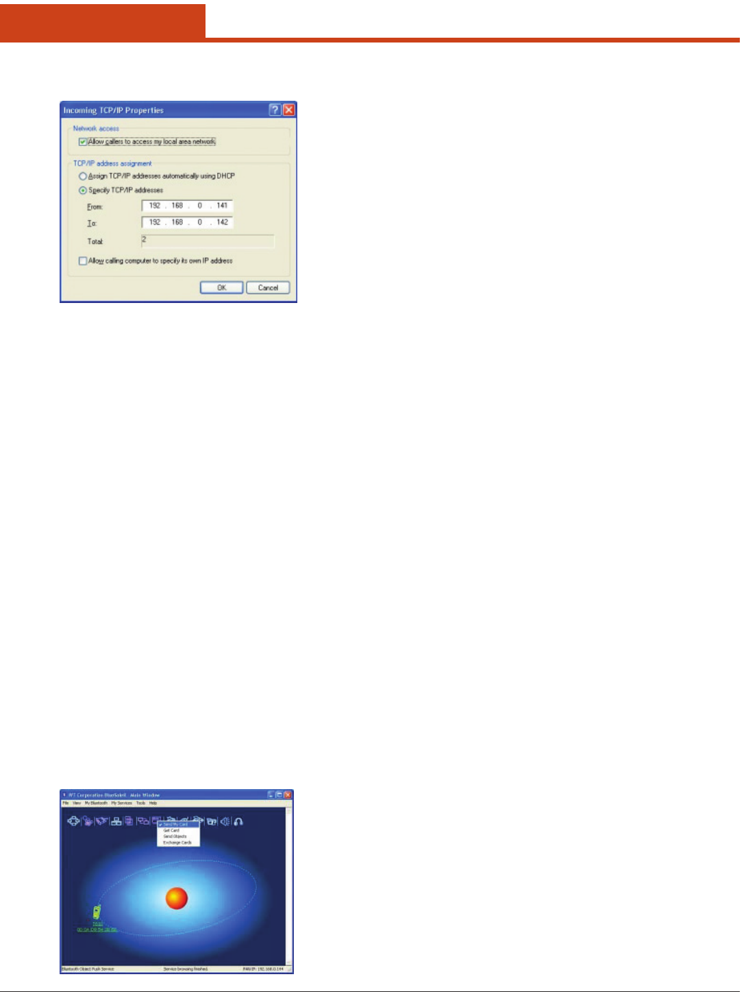
112
7.0 Bluetooth
(3) Select Specify TCP/IP addresses and enter the range of IP
addresses assigned to LAP clients.
7.3.9 Object Push
e Bluetooth Object Push Prole (OPP) enables users to send and re-
ceive Personal Information Management (PIM) data objects (including
messages, notes, calendar items, and business cards) to and from a Blue-
tooth enabled PDA or mobile phone.
e objects supported include:
• Contacts(*.vcf)
• Calendaritems(*.vcs)
• Notes(*.vnt)
• Messages(*.vmg)
Typical Usage
• PushobjectstoaBluetoothenabledmobilephoneorPDA
• ReceiveobjectsfromaBluetoothenabledmobilephoneorPDA
Note: If you would like to push PIM objects to a PDA, make sure
that the PDA is ready to receive a PIM object before you start.
If necessary, enable Object Push on the PDA. For instructions,
refer the PDA’s user documentation.
7.3.9.1 Push Objects to a Bluetooth-Enabled
Mobile Phone
ere are two methods to push objects:
Method 1: From BlueSoleil Main Window: Double-click on the mobile
phone or PDA icon to browse for service information. e
Object Push Service icon should be highlighted at the top
of the screen. Right click the Object Push Service icon, and
in the pop-up menu click Send My Card.
• Send My Card:
Send your default business card.
• Get Card:
Get the phone’s default business card.
• Send Objects:
Select objects (PIM les ending in .vcf, .vcs, .vnt, or .vmg)
and send them to the phone.
• Exchange cards:
Have your computer and the phone to exchange their de-
fault business cards.
Method 2: From MS Outlook:
(1) Select the contact that you would like to send.
(2) In Outlook, click on the Push button on the toolbar, or
click:
File | Push
(3) e Bluetooth Neighbors screen will appear. In the device
list, select the phone or PDA that you wish to push the contact
to. Click on the Push button.
7.3.9.2 Receive Objects from a Bluetooth En-
abled Mobile Phone
Step 1: Congure the parameters for the object push. From the Main
Window, click My Services | Properties. Click on the Object
Push tab.
Step 2: Start the Object Push service, following the instructions in
7.2.3. Do not initiate a connection, only start the service so
that your computer will be ready to receive objects.
Step 3: Send objects from the phone. For instructions, refer to your
phone’s user documentation.
Notes:
• BlueSoleil creates a Bluetooth folder (with Inbox and Outbox
subfolders) in your My Documents folder for use with Object
Push. e Inbox is used to save objects received from other de-
vices. e Outbox is used to save objects sent out from your com-
puter.
• Yourcansetyourdefaultbusinesscardbyclicking
My Services | Object Push
In the Send My Business Card eld, browse to select a contact as
your default business card.
7.3.10 Personal Area Networking
e Bluetooth Personal Area Networking (PAN) Prole enables PCs,
laptops, PDAs, and other Bluetooth enabled devices to form either of
two kinds of PAN networks. In a Group ad-hoc Network (GN), which
functions as an isolated network, multiple PAN Users (PANUs) are
linked together via a GN controller.
Alternatively, a PAN can consist of multiple PANUs linked to a Network
Access Point (NAP), which provides access to external Local Area Net-
work (LAN) infrastructure. BlueSoleil supports all three of these device
roles — GN (controller), PANU, and NAP.
Typical Usage
• Group Ad-hoc Network (Peer-to-peer networking) — One device
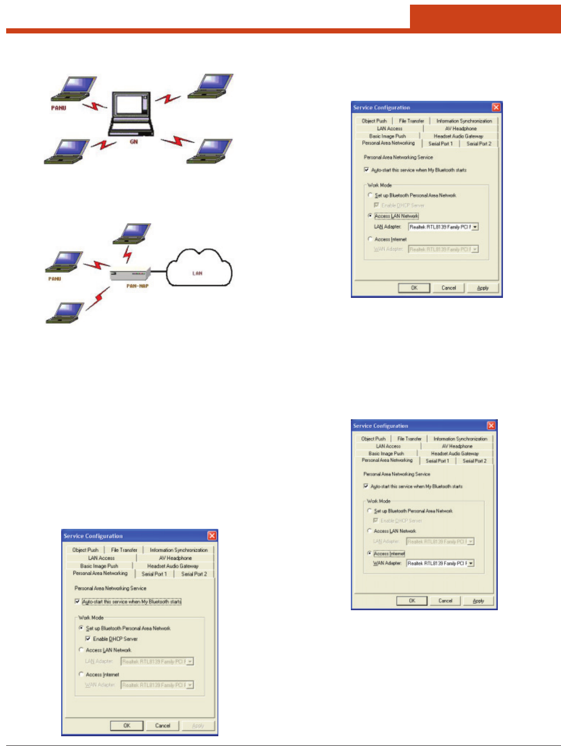
113
7.0 Bluetooth
acts as the GN, and others function as PANU devices. ese com-
puters can visit each other or use an application based on TCP/IP.
• AccessaLANviaaNetworkAccessPoint(ora ComputerActing
as a NAP). Aer the computers connect to the NAP, they become
members of the LAN and can directly communicate with other
computers in the LAN.
7.3.10.1 Connecting the PAN User (PANU)
Step 1: Connect to the server’s Personal Area Network service, fol-
lowing the instructions in 7.2.3.
Step 2: Wait a few seconds for BlueSoleil to obtain and display your
computer’s IP address.
7.3.10.2 Conguring the NAP/GN
Click Bluetooth Service | Properties and click on the Personal Area Net-
work tab.
Scenario 1 — Group Ad-hoc Network
Select Set up Bluetooth Personal Area Network and Enable DHCP Serv-
er (Figure 3.9).
A DHCP server will be started on the GN. e PANU can obtain an IP
address automatically from this DHCP server if the PANU does not set
static IP address for the BT Network Adapter.
Scenario 2 — Access LAN via PAN-NAP
Select Access LAN Network and select a physical network adapter,
through which the NAP connects to a LAN, as the LAN Adapter (Fig-
ure 3.10).
Scenario 3 — Access the Internet via NAP
Select Access Internet and select a physical network adapter, through
which the NAP connects to Internet, as the WAN Adapter (Figure 3.11).
It will automatically enables NAT (Network Address Translation, please
refer to Windows Help Topic) function and a DHCP server.
Note: e BT Network Adapter on the PANU side must be set to
obtain an IP address automatically. e IP address is in the
form of 192.168.2.xxx, such as 192.168.2.1.
7.3.11 Printer
e Bluetooth Printer Prole (HCRP) enables your computer to connect
to a Bluetooth enabled printer.
Typical Usage
Print documents on a Bluetooth enabled Printer.
Step 1: Connect to the printer’s printer service.
(a) If your computer does not have the correct printer driv-
ers installed, BlueSoleil will prompt you to do so. Install the
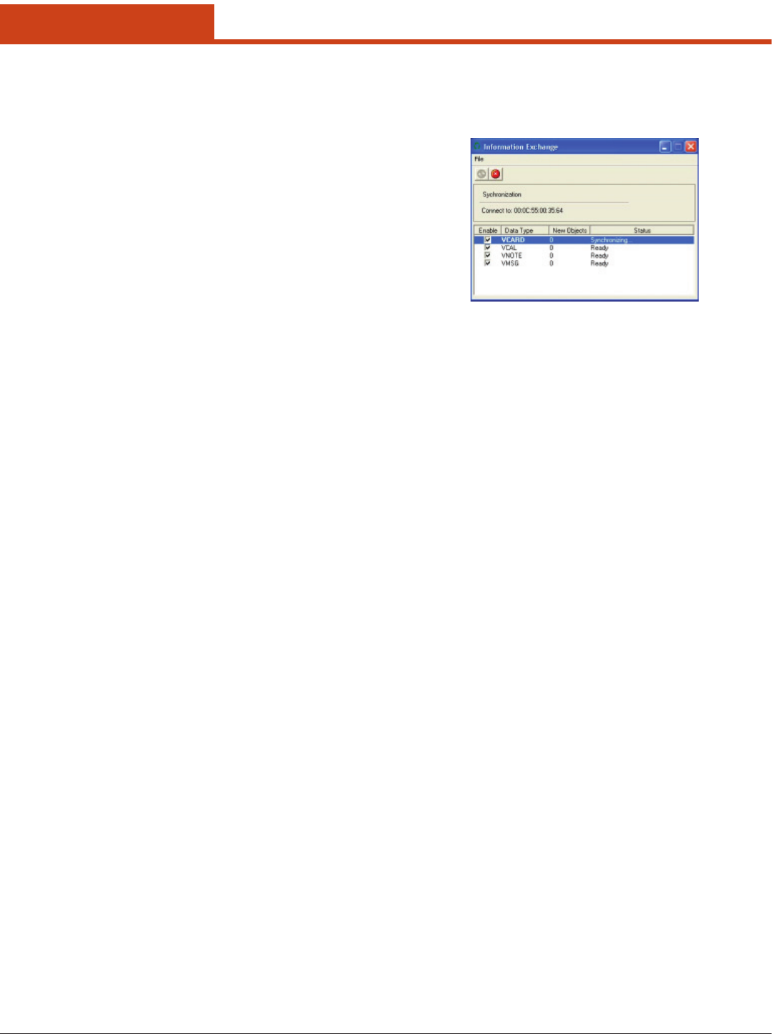
114
7.0 Bluetooth
driver for the printer, and remember to set the printer port
to the correct COM port number. To determine the correct
COM port number, in the Main Window, right-click on the
device icon. In the pop-up menu, select Status.
(b) If the printer driver has been installed, a message indicates
that the printer is ready.
Step 2: Print documents using the Bluetooth enabled printer. In the ap-
plication, be sure to select the correct printer and printer port.
7.3.12 Serial Port
e Bluetooth Serial Port Prole (SPP) provides PCs, laptops, PDAs,
GPS receivers, cordless serial adapters, and other Bluetooth enabled
devices with a virtual serial port, enabling them to connect with each
other wirelessly via Bluetooth instead of with a serial cable.
BlueSoleil supports four Bluetooth Serial Ports for outgoing connec-
tions and two Bluetooth Serial Ports for incoming connections.
Typical Usage
Connect to other Bluetooth enabled devices via the Serial Port Connect
to a PDA.
Step 1: Connect to the PDA’s Serial Port service, following the in-
structions in 7.2.3.
Step 2: Use ActiveSync or any other application that uses a serial con-
nection.
Note:
• SerialPortAuto-Connectionfunction
Once a target device is assigned to a specic serial port, (e.g.,
COM5), whenever an application opens that serial port number,
BlueSoleil will automatically connect to the target device. Simi-
larly, whenever an application closes the Bluetooth serial port,
BlueSoleil will stop the connection. To check which devices are
assigned to which COM ports, click Tools | Congurations |
Connect With.
• SomeapplicationsonlyallowyoutousealimitedrangeofCOM
port numbers. If the application does not allow you to use a
COM port number assigned by BlueSoleil, you will not be able to
use BlueSoleil with your application.
7.3.13 Bluetooth Synchronization
e Bluetooth Synchronization (SYNC) Prole enables users to syn-
chronize PIM objects on their computer with that of other Bluetooth
enabled computers as well as Bluetooth enabled mobile phones, PDAs,
and other devices.
Four kinds of objects are supported:
• Contacts(*.vcf)
• Calendars(*.vcs)
• Notes(*.vnt)
• Messages(*.vmg)
Supported MS Outlook versions: Outlook 2000, Outlook 2002 (xp),
Outlook 2003.
Typical Usage
Synchronize your computer with a Bluetooth enabled mobile phone.
Step 1: Connect to the mobile phone’s Synchronization service, fol-
lowing the instructions in 7.2.3.
Step 2: A synchronization dialog will appear (refer to Figure 3.12).
Click on the Start button to synchronize. Contacts, calendars,
notes and emails in MS Outlook will be synchronized with
those on the phone.
Note:
• UserscanstartsynchronizationfromMSOutlookusingtheBlue-
tooth Add-In menus and buttons installed with BlueSoleil.
• BlueSoleil can act as synchronization server. Click My Services |
Properties. Click on the Information Synchronization tab, and se-
lect the type of PIM objects that you would like to synchronize.
115
7.0 Bluetooth
7.4 BlueSoleil User Guides
7.4.1 BlueSoleil Environment
7.4.1.1 Main Window
e Main Window displays the local device (red ball) and the remote
devices detected in range. Connecting and disconnecting operations
are conducted here. Connections are indicated by green dashed lines
between the local device and connected remote devices.
By default BlueSoleil starts with the Main Window open. To return to
the Main Windows aer switching views, click View | Main Window.
7.4.1.1.1 Local Bluetooth Device
e Local Bluetooth enabled device, known as “My Device,” represents
the user’s computer that is running BlueSoleil.
— Operations
• Hoveryourmouseovertheredballtodisplaythelocaldevice’sBlue-
tooth name and address.
• ClickontheredballtostartorstopsearchingforBluetoothdevices
in range.
• Right-clickontheredballtodisplayapop-upmenuofrelatedop-
erations (e.g., General Inquiry, My Services, Security, etc.).
7.4.1.1.2 Remote Bluetooth Devices
Remote devices are other Bluetooth enabled devices that are in the radio
range of your local device. BlueSoleil uses dierent icons to indicated
dierent types of remote devices.
Personal
Computer
Laptop
Modem Mobile
Phone
PDA LAN Access
Point
Keyboard Mouse
Microphone HiFi Audio
Loud
Speaker
Headset
Printer Scanner
Fax Camera
Game Con-
troller
Server
Unknown
Device
— Icon Meanings
Remote devices can be in any of three states, which BlueSoleil indicates
with dierent colors.
• White—Idle.enormalstateofthedevice.
• Yellow—Selected.Youhaveselectedthedevice.
• Green—Connected.edeviceisconnectedtoyourcomputer.
— Operations
• Single-clickontheicontoselect.
• Double-clickontheicontosearchfortheservicessupportedbythe
remote device.
• Right-clickontheicontodisplayapop-upmenuofrelatedopera-
tions (e.g., Refresh Devices, Pair Devices, Connect, etc.).
7.4.1.1.3 Bluetooth Service Buttons of Remote Device
Service buttons at the top of the Main Window represent a range of
Bluetooth services potentially supported by Remote Devices.
PAN DUN
SPP LAP
FTP SYNC
OPP HCRP
HID FAX
BIP AV
Headset
— Icon Meanings
ere are 3 states for the service icons, indicated by dierent colors.
• White—Idle.enormalstate.
• Yellow—Available.eBluetoothserviceisavailableontheselect-
ed remote device.
• Green—Connected.eBluetoothserviceisactiveinaconnection
with the remote device.
— Operations
• Hoveryourmouseovertheserviceicontodisplaythenameofthe
service.
• Single-clickontheserviceicontoconnect.
• Right-clickontheserviceicontodisplayapop-upmenuofrelated
operations.
7.4.1.2 Service Window
e Service Window displays the local Bluetooth services, (i.e., the Blue-
tooth services supported by BlueSoleil). Use the Service Window to start
and stop services, as well as to congure service properties. To access
the Service Window, click:
View | Service Window
116
7.0 Bluetooth
Local Service List
e Local Service List displays all of the Bluetooth services supported by
the local computer. Use this screen to start/stop services.
PAN SPP
OPP FTP
SYNC LAP
AV BIP
Headset AG
— Icon Meanings
ere are 3 states for the local Bluetooth services, indicated by dierent
icon colors.
• White–Idle.eservicehasnotbeenstarted.
• Yellow–Started.elocalBluetoothservicehasbeenstarted.
• Green–Connected.Someremotedevicehasconnectedtotheservice.
— Operations
• Single-clickontheicontoselecttheservice.
• Double-clickontheicontoStart/Stopaservice.
• Right-clicktodisplayapop-upmenuofrelatedoperations.
7.4.1.3 Menus
BlueSoleil contains the following six menus:
• FileMenu
• ViewMenu
• MyBluetoothMenu
• MyServicesMenu
• ToolsMenu
• HelpMenu
File Menu
Hide — Hide the BlueSoleil window. Connections can still run when the
window is hidden.
Always on Top — Keep the BlueSoleil window always on top.
Exit — Exit BlueSoleil.
You can also exit BlueSoleil by right-clicking on the task tray icon at the
bottom of your screen. In the pop-up menu, click Exit.
View Menu
Main Window — Show the BlueSoleil Main Window.
Service Window — Show the BlueSoleil Service Window.
Arrange Devices — Arrange remote devices by Device Name, Device
Address, or Device Type
Refresh Devices — Refresh the list of remote devices detected by Blue-
Soleil.
Note: If you select Refresh Devices, the list of previously detected
devices will not be cleared. To initiate a new device search that
will rst clear the list, press F5.
My Bluetooth Menu
Bluetooth Device Inquiry -— Search for other Bluetooth enabled de-
vices in range.
Bluetooth Service Browsing — Browse for the services of the selected
remote device.
Security — Congure the security settings of the local device (e.g., pass-
key requirements, data encryption, etc.).
Properties — Congure the properties of the local device (e.g., device
name, accessibility, etc.).
My Services Menu
Start Service — Start the selected local Bluetooth service.
Stop Service — Stop the selected local Bluetooth service.
Status — View the status of the selected local Bluetooth service.
Properties — Congure the properties of the local Bluetooth services
(e.g., automatic connections, shared le locations, etc.).
Tools Menu
My Shortcuts — Display dialog Bluetooth Shortcuts.
Connect: Connect the selected shortcut.
Delete: Delete the selected shortcut.
Find Device — Click to nd a device, by either of two search criteria:
By Bluetooth Device Address:
Enter a Bluetooth device address, in standard format (xx:xx:xx:xx:xx:xx),
and click on the Find button. e device with the specied address will
appear highlighted in the Main Window.
By Name:
Check the By Name box, enter the Name of the device, and click on the
Find button. e device with the specied name will appear highlighted
in the Main Window.
Add New Device — Add a remote device by entering its Bluetooth de-
vice address.
Add Device From History — Add a remote device from the history list.
Add: Add the selected device.
Delete: Clear the selected device from the history list.
Congurations->Connect With — If desired, assign a remote device to
automatically connect with a Bluetooth serial port whenever an applica-
tion opens the specied port.
Assign: Assign a device to the selected port.
Remove: Remove the Auto-Connection device assignment for the se-
lected port.
Congurations-> Unplug HID — Remove Human Interface Devices
from BlueSoleil.
Unplug: Unplug the selected HID device.
When you rst connect the HID device to your computer, BlueSoleil
sets up the devices so that they will automatically reconnect in case the
connection is ever broken. Aer you unplug an HID device, it will no
longer automatically reconnect to your computer.
Bluetooth Device — Advanced hardware conguration, recommended
for advanced users only. Please refer to 4.2 Hardware Conguration for
more details.

117
7.0 Bluetooth
Help Menu
Contents and Index — Access BlueSoleil Online Help.
About BlueSoleil — Information about your version of BlueSoleil.
7.4.2 Device Congurations
7.4.2.1 Hardware Conguration
BlueSoleil supports the following kinds of Bluetooth radio adapters:
USB and CF card.
To access the hardware conguration screens, click
Tools | Bluetooth Device…
Bluetooth Device
Select the type of Bluetooth enabled device that you plan to use, either a
USB adapter or a CompactFlash (CF) card.
Advanced Conguration
e Advanced Conguration page will be enabled only if you selected
CF in the Bluetooth Device screen. Use the Advanced Conguration
screen to congure detailed parameters including COM Port, Baud
Rate, Byte Size, Parity, Stop Bits, and Flow Control.
7.4.2.2 Properties Conguration
To congure the properties of your local device, click:
My Bluetooth | Properties…
General
— Device Name
e local device’s name, which will be shown to other Bluetooth enabled
devices.
— Device Type
e device type of your local computer, (i.e., Desktop, Laptop or Server).
— Device Address
e address of the local device. Every Bluetooth enabled device has a
unique device.
Accessibility
— Connecting Mode
• Connectable: Permits other Bluetooth enabled devices to connect
with your computer.
• Non-Connectable:ProhibitsotherBluetoothenableddevicesfrom
connecting with your computer.
— Discovery Mode
• General Discoverable: Permits other Bluetooth enabled devices to
detect your computer.
• Limited Discoverable: Permits other Bluetooth enabled devices to
detect your computer with Limited Inquiry.
• Non-Discoverable:ProhibitsotherBluetoothenableddevicesfrom
detecting your computer.
— Bonding Mode (Pairing Mode)
• Accepts Bonding: Allow other Bluetooth enabled devices to pair
with your computer. If the other device initiates a pairing procedure
with your computer, each device must enter the same passkey before
the they will be paired.
• Does Not Accept Bonding: Rejects pairing attempts initiated by
other Bluetooth enabled devices.
Hardware
View information about your Bluetooth hardware.
• Manufacturer:emanufacturerofthelocalBluetoothdevice.
• HCIVersion:eHCIversionofthelocalBluetoothdevice.
• HCIEdition:eHCIeditionofthelocalBluetoothdevice.
• LMPVersion:eLMPversionofthelocalBluetoothdevice.
• LMPSubversion:eLMPsubversionofthelocalBluetoothdevice.
7.4.3 Security Conguration
Use the Security Conguration screens to specify the security settings
of your local device.
7.4.3.1 Pair / Un-pair Devices
Once a remote device has paired with your computer by exchanging
passkeys, passkeys will no longer be required for further connections
between your computer and the device.
7.4.3.1.1 How to pair with another device
— Automatically
If a passkey is required for connection, the devices will be paired auto-
matically the rst time they successfully exchange passkeys and con-
nect. Aer a device has successfully paired with your computer, the re-
mote device icon in the Main Window will have a red checkmark next
to it.
— Manually
In the Main Window, right click on the device icon, and in the pop-up
menu, select Pair Device. In the Enter Bluetooth Passkey screen, enter
the same passkey that you enter on the remote device. Aer a device
has successfully paired with your computer, the remote device icon will
have a red checkmark next to it.
7.4.3.1.2 How to un-pair with another device
In the Main Window, right-click on the device icon, and in the pop-up
menu, select Unpair. e red checkmark next to the device icon will
disappear.
7.4.3.2 General Security
To access the security conguration screen, click:
My Bluetooth | Security…
7.4.3.2.1 Security Level
— Low
If checked, other devices will be able to access your device freely without
entering a passkey.
However, if the remote device requires a passkey to connect, then both
devices need to exchange passkeys.
— Medium
e medium level provides service level security. You can assign the ap-
propriate level of access for each specic service. For more details, see
4.3.4 Local Services Security.
— High
If checked, passkeys must be exchanged for every incoming and outgo-
ing connection, unless the two devices have already paired in the past.

118
7.0 Bluetooth
7.4.3.2.2 Bluetooth Passkey
— Set Default Passkey
Use this setting to create a default passkey for all connections. is saves
you the eort of manually creating a passkey whenever one is required.
7.4.3.2.3 Data Encryption
— Enable Data Encryption
If checked, the data transmitted will be encrypted.
7.4.3.3 Managing Device Pairings
To access the device security conguration screen, click My Blue-
tooth | Security and click on the Devices tab.
— Paired Devices
is screen lists devices which have already paired with the local device.
— Remove Pairing
Click to remove the pairing relationship between the selected device
and the local device.
— Authorization
Click to select the local Bluetooth services that you wish to allow the se-
lected paired device to use. A list of local services will appear. Select the
services you wish to allow on the remote device, then click OK.
Note: e screen will only list the local services that require authen-
tication. e local services that do not require authentication
can be accessed freely.
e Authorization button is enabled only when the Security Level is set
to Medium.
7.4.3.4 Local Services Security
To access the local services security conguration screen, click:
My Bluetooth | Security
and click on the Services tab. You can only congure security for lo-
cal services when the Security Level is set to Medium. (Set the Security
Level in the General Security screen.)
7.4.3.4.1 Local Services:
— Authentication
If checked, a passkey is required whenever a remote device attempts to
connect with this service.
— Encryption
If checked, data transmitted between devices for this service will be en-
crypted.
— Authorization
Click to select the devices you wish to allow to use the selected service.
In the Service Authorization screen, enter the following settings:
— Trusted Devices
Select to trust devices listed in this screen to use the selected service on
your device.
A device can freely access the service from your local device when trust-
ed. Click Add/Remove to edit the device list.
— Trust all devices
Connection requests will be accepted from every device.
— Prompt user if the device is not trusted for this service
If a non-trusted device attempts to access the service, a dialog will ap-
pear to allow you to accept or reject the connection.
— Reject devices from using the service if not trusted for
the service
If a non-trusted device attempts to access the service, the connection
will be rejected automatically without informing the user.
Notes: If a device is trusted for a service, it may connect to this ser-
vice on your local device without informing you.

119
AES AES-CCMP is the encryption method dened with IEEE
802.11i and certied with WPA2. Stronger than RC4 (which
is used with both WEP and TKIP), AES-CCMP is considered
sucient for FIPS 140-2.
AES - Advanced Encryption Standard
CCMP - Counter Mode CBC-MAC Protocol
Authentica-
tion
e process of verifying the identity of:
• Astationattemptingtogainaccesstoanetwork.
• Anetworktowhichastationistryingtogainaccess.
IEEE 802.1X, which is the authentication component of WPA
and WPA2, performs mutual authentication through an
Extensible Authentication Protocol (EAP) type. With mutual
authentication, the network authenticates the station and the
station authenticates the network.
Auth Type Auth Type indicates the 802.11 authentication type used when
associating to an access point. SCU authentication type param-
eters include:
• Open-istwo-stepauthenticationtypeinvolvesthestation
sending a request (usually a randomly generated key) to the
access point. e access point sends an authentication response
that contains a success or failure message. Once accepted, the
keyisonlyusedforashortperiodoftime;thenanewkeyis
generated and agreed upon.
• Shared-With a sharedauthenticationtype, boththestation
and the access point have the same “shared” key or passphrase.
• LEAP(Network-EAP)
Note: See http://www.cisco.com/en/US/products/hw/
wireless/ps4570/products_configuration_exam-
ple09186a00801bd035.shtml for a Cisco explanation
of 802.11 authentication using Open and Network-
EAP. e Summit Client Utility refers to Network-EAP
as LEAP.
Note: Summit highly recommends the use of Open which is
also the SCU default. is setting can be edited from
the Prole window of SCU.
Bit Rate Bitrate is the measurement of how much data is transmitted
in a given amount of time from one location to another. It is
generally measured in bits per second (bps), kilobits per second
(Kbps), or megabits per second (Mbps).
CAM CAM (Constantly Awake Mode) is a power save mode that
keeps the radio powered up continuously to ensure there is
minimal lag in response time. is power save setting con-
sumes the most power but oers the highest throughput.
CKIP CKIP (Cisco Key Integrity Protocol) and CMIC (Cisco Mes-
sage Integrity Check) are Cisco-dened predecessors to WPA
TKIP and are supported only on Cisco Wi-Fi infrastructure.
An SCU prole setting of CKIP (not CKIP-EAP) means that
the encryption keys are dened in SCU. An SCU prole set-
ting of CKIP-EAP means that the encryption keys are derived
dynamically from an EAP authentication.
Note: If the SCU active prole has an encryption setting of
CKIP or CKIP EAP, then the Summit radio associates
or roams successfully to an access point that is cong-
ured with the following:
• eSSIDandotherRFsettingsoftheSCUactiveprole
• eauthenticationmethodoftheSCUactiveprole
• Anyofthefollowingencryptionsettings:
– WEP only (no CKIP or CMIC)
– WEP with CKIP
– WEP with CMIC
– WEP with CKIP and CMIC
Note: Summit recommends the use of TKIP or WPA2.
Appendix A — EAP Types
Client Name For the SCU, the device name assigned to the Summit radio
and the client device that uses it.
Note: If CCX Features are set on the SCU Global settings
page, then the client name is relayed and used for as-
sociation.
Credentials e Credentials button on the Prole window of SCU allows
you to add or edit the authentication credentials for the
selected EAP type. See 6.1.2.6 EAP Credentials on p. 71
fopr more information.
EAP See 6.1.2.6 EAP Credentials on p. 71 for more information.
Fast Fast is a power save mode that switches between PSP (Power
Save Protocol) mode and CAM mode, depending on network
trac. For example, it switches to CAM when it is receiving
a large number of packets and switches back to PSP aer the
packets have been retrieved. Fast is recommended when power
consumption and throughput is a concern.
Encryption Encryption involves scrambling transmitted data so that it can
be read only by the intended receiver, which has the proper key
to decrypt unscramble the encrypted data. In Summit Client
Utility, the Encryption setting in a prole can refer not just to
an encryption method but also to an authentication method
and an encryption key management protocol.
For more information, see “SCU Encryption Settings” Table.
Maximum Maximum (Max PSP) is a power save mode where the access
point buers incoming messages for the radio. e radio oc-
casionally ‘wakes up’ to determine if any buered messages
are waiting and then returns to sleep mode aer it requests
each message. is setting conserves the most power but also
provides the lowest throughput. It is recommended for radios
in which power consumption is most important (such as small
battery-operated devices).
Power Savez Indicates the radio’s current power save setting. Power save mode
allows you to set the radio to its optimum power-consumption
setting.
Maximizing battery life for full shi operation is an important
consideration for vendors and users of hand-held data termi-
nals and similar devices. Summit provides a number power save
modes that can signicantly reduce the radio’s power consump-
tion and maximize the battery life of the host device.
Summit supports the three following power save modes:
• CAM(ConstantlyAwakeMode)
• Fast
• Maximum
When in power save mode, the radio “sleeps” most of the time
and “wakes up” only when it has data that needs to be sent to the
infrastructure (or at an interval determined between the station
and the access point). When the radio is awake, the access point
also delivers to the station any data that has been buered dur-
ing the radio’s sleep period.
Radio Mode Radio mode is an SCU Prole setting that indicates the use of
802.11a, 802.11g, 802.11b, and 802.11n frequencies and data
rates when interacting with an access point, or the use of ad
hoc mode to associate to a station radio instead of an access
point.
When SCU operates with a Summit 802.11g radio, an adminis-
trator can select from among the following radio mode values:
• Bratesonly-1,2,5.5,and11Mbps
• Gratesonly-6,9,12,18,24,36,48,and54Mbps
• BGratesfull-AllBandGrates
• BGSubset-1,2,5.5,6,11,24,36,and54Mbps.isshould
only be used with Cisco APs running IOS in autonomous
mode (without controllers). For Cisco APs that are tied to
controllers and for non-Cisco APs, Summit recommends BG
rates full.
(cont’d)

120
Radio Mode
(cont’d)
• AdHoc-Whenselected,theSummitradiousesadhocmode
instead of infrastructure mode. In infrastructure mode, the
radio associates to an AP. In ad hoc mode, the radio associ-
ates to another station radio that is in ad hoc mode and has
the same SSID and, if congured, static WEP key.
Note: e default is BG rates full.
Note: See “802.11a/g Radio Mode with 802.11g Radio” for ad-
ditional information.
When SCU operates with a Summit 802.11a/g radio, an admin-
istrator can select from the following radio mode values:
• Bratesonly-1,2,5.5,and11Mbps
• Gratesonly-6,9,12,18,24,36,48,and54Mbps
• BGratesfull-AllBandGrates
• Aratesonly-6,9,12,18,24,36,48,and54Mbps(sameasG
rates)
• ABG rates full - All A rates and all B and G rates, withA
rates (the 802.11a radio) preferred (see “Preferred Band for
802.11a/g Radio” for more information).
• BGA rates full - All B and G rates and all A rates, with B
and G rates (the .11g radio) preferred (see “Preferred Band for
802.11a/g Radio” for more information).
• BGSubset-1,2,5.5,6,11,24,36,and54Mbps.isshould
only be used with Cisco APs running IOS in autonomous
mode (without controllers). For Cisco APs that are tied to
controllers and for non-Cisco APs, Summit recommends BG
rates full.
• Adhocmodeinsteadofinfrastructuremode.Ininfrastruc-
ture mode, the radio associates to an AP. In ad hoc mode,
the radio associates to another station radio that is in ad hoc
mode and has the same SSID and, if congured, static WEP
key.
Note: e default is ABG rates full.
Note: See “802.11a/g Radio Mode with 802.11g Radio” for ad-
ditional information.
Preferred Band for 802.11a/g Radio
When the radio mode value is ABG rates full, the 5 GHz (A)
band is preferred over the 2.4 GHz (BG) band. When the
radio mode value is BGA rates full, the 2.4 GHz (BG) band is
preferred over the 5 GHz (A) band.
• AdHoc- Whenselected,the Summitradio usesWhen try-
ing to associate to an access point, the radio considers access
points in the preferred band. If the radio is able to associate
to one of these access points, then the radio will not try to
associate to an access point in the other band. e only time
that the radio attempts to associate to an access point in the
non-preferred band is when the radio is not associated and
cannot associate in the preferred band.
When roaming, the radio considers only access points in the
current band (the band in which the radio is currently associ-
ated). e radio will consider an access point in the other band
only if it loses association.
802.11a/g Radio Mode with 802.11g Radio
When an administrator tries to create or edit a prole, SCU de-
termines which radio is operating in the device and populates
the available radio mode values according to the radio type.
Suppose a prole created for an 802.11a/g card is loaded on a
device with an 802.11g card. If a radio mode value of A rates
only, ABG rates full, or BGA rates full was set in the prole,
then SCU displays a value of BG rates full. If the administrator
does not save any changes to the prole, then SCU leaves the
prole, including the radio mode, unchanged. If the admin-
istrator saves any changes to the prole, then SCU saves the
radio mode value as BG rates full.
SSID Service Set Identier. Unique name of up to 32 characters that
identies a particular 802.11 WLAN.
e SSID is attached to the header of packets that are sent over
a wireless network.
Appendix A — EAP Types (cont’d.)
Tx Power In SCU, Tx Power displays on the Status window to indicate
of the power of the radio, in milliwatts (mW). is value can
beoverwrittenbytheAP;theAPcandictatetotheclientwhat
power to use.
WEP WEP (Wired Equivalent Privacy) encrypts transmitted data
using 64-bit or 128-bit encryption. WEP, which was dened
with the original IEEE 802.11 standards, is not recommended
because a WEP key can be “broken” in less than an hour using
commonly available tools.
WPA/WPA2 WPA (Wi-Fi Protected Access) and WPA2 (Wi-Fi Protected
Access 2) are security certications dened by the Wi-Fi Al-
liance. To earn a WPA or WPA2 certication, a product must
pass a set of tests that elements of the security specication
have been implemented correctly. Since March 2006, WPA2 is
mandatory for all new equipment that is certied by the Wi-Fi
Alliance.
Both WPA and WPA2 include three security elements: authen-
tication, encryption, and encryption key management. WPA
and WPA2 support the same authentication methods and
similar key management methods. e primary dierence be-
tween the two is in the area of encryption: WPA denes TKIP
astheprimaryencryptionmethod;WPA2denesAES-CCMP
as the primary encryption method.
Both WPA and WPA2 include a Personal version and an Enter-
prise version. With WPA-Personal and WPA2-Personal, which
SCU refers to as WPA-PSK and WPA2-PSK, authentication
is done through a pre-shared key (PSK) or passphrase that is
statically congured on every client device and infrastructure
device. With WPA-Enterprise and WPA2-Enterprise, authenti-
cation is IEEE 802.1X, which uses an EAP type. WPA2-Enter-
prise is the equivalent of IEEE 802.11i, the ratied standard for
Wi-Fi security.

121
Prole Setting Authentication Encryption Key Management
None None None None
WEP None WEP Static (in SCU)
WEP EAP EAP Type WEP Dynamic
(from EAP)
CKIP None WEP+CKIP+CMIC Static (in SCU)
CKIP EAP EAP Type WEP+CKIP+CMIC Dynamic
(from EAP)
WPA-PSK PSK/password
(in SCU)
TKIP WPA
WPA-TKIP EAP Type TKIP WPA
WPA CCKM EAP Type TKIP WPA+CCKM
WPA2-PSK PSK/password
(in SCU)
AES-CCMP WPA2
WPA2 AES EAP Type AES-CCMP WPA2
WPA2 CCKM EAP Type AES-CCMP WPA2+CCKM
Appendix B — Encryption Settings
In SCU, the Encryption setting in a prole can refer not just to an encryption method but also to an
authentication method and an encryption key management protocol. e following table provides
an explanation of SCU Encryption settings:

122
Toll Free : +1 (855) DAP-TECH (327-8324)
www.daptech.com
Copyright © 2012, DAP Technologies
All rights reserved.
7450 South Priest Drive
Tempe, Arizona, 85283 USA
Tel: +1 (855) 327-8324
Fax: +1 (480) 705-4216
United States
875, boul. Charest O. Bureau 200
Québec (QC) Canada G1N 2C9
Tel: +1 (800) 363-1993
Fax: +1 (418) 681-0799
Canada
25 Nufeld Way
Abingdon, England OX 14 1RL
Tel: +44 (0) 1235 462130
Fax: +44 (0) 1235 462131
Europe, Middle East, Africa