TransCore 76007 FHSS TRANSCEIVER MODULE User Manual M6e Transcore Developer s Guide
TransCore FHSS TRANSCEIVER MODULE M6e Transcore Developer s Guide
Contents
Users Manual

875-0034-02 Rev1
Mercury®6e - Transcore Developer’s Guide
Government Limited Rights Notice: All documentation and manuals were
developed at private expense and no part of it was developed using
Government funds.
The U.S. Government’s rights to use, modify, reproduce, release, perform,
display, or disclose the technical data contained herein are restricted by
paragraph (b)(3) of the Rights in Technical Data — Noncommercial Items
clause (DFARS 252.227-7013(b)(3)), as amended from time-to-time. Any
reproduction of technical data or portions thereof marked with this legend must
also reporduce the markings. Any person, other than the U.S. Government, who
has been provided access to such data must promptly notify ThingMagic, Inc.
ThingMagic, Mercury, Reads Any Tag, and the ThingMagic logo are trademarks
or registered trademarks of ThingMagic, Inc.
Other product names mentioned herein may be trademarks or registered
trademarks of ThingMagic, Inc. or other companies.
© Copyright 2000–2009 ThingMagic, Inc. All Rights Reserved
ThingMagic, Inc.
One Broadway, 5th floor
Cambridge, MA 02142
866-833-4069
Revision 1
August, 2009

3
Contents
Introduction to the Mercury6e-Transcore Module . . . . . . . . . . . . . . . . . . . . . . . . . . . . . .13
Hardware Overview . . . . . . . . . . . . . . . . . . . . . . . . . . . . . . . . . . . . . . . . . . . . . . . . . . . . . . . . . . . . . . . . . . . . . . . . . 13
Microcontroller 14
RFID ASIC 14
Connectors 14
M6e-TC Digital Connectors . . . . . . . . . . . . . . . . . . . . . . . . . . . . . . . . . . . . . . . . . . . . . . . . . . . . . . . . . . . . . 15
Firmware Overview . . . . . . . . . . . . . . . . . . . . . . . . . . . . . . . . . . . . . . . . . . . . . . . . . . . . . . . . . . . . . . . . . . . . . . . . . 15
Boot Loader. . . . . . . . . . . . . . . . . . . . . . . . . . . . . . . . . . . . . . . . . . . . . . . . . . . . . . . . . . . . . . . . . . . . . . . . . . 16
Application Firmware . . . . . . . . . . . . . . . . . . . . . . . . . . . . . . . . . . . . . . . . . . . . . . . . . . . . . . . . . . . . . . . . . . 16
Verifying Application FW Image CRC 16
Functionality of the Embedded Modules . . . . . . . . . . . . . . . . . . . . . . . . . . . . . . . . . . . . . .17
Regional Support . . . . . . . . . . . . . . . . . . . . . . . . . . . . . . . . . . . . . . . . . . . . . . . . . . . . . . . . . . . . . . . . . . . . . . . . . . .17
Frequency Setting . . . . . . . . . . . . . . . . . . . . . . . . . . . . . . . . . . . . . . . . . . . . . . . . . . . . . . . . . . . . . . . . . . . . . . . . . .18
Frequency Units . . . . . . . . . . . . . . . . . . . . . . . . . . . . . . . . . . . . . . . . . . . . . . . . . . . . . . . . . . . . . . . . . . . . . . 18
Frequency Hop Table . . . . . . . . . . . . . . . . . . . . . . . . . . . . . . . . . . . . . . . . . . . . . . . . . . . . . . . . . . . . . . . . . . 19
Frequency Hop Interval. . . . . . . . . . . . . . . . . . . . . . . . . . . . . . . . . . . . . . . . . . . . . . . . . . . . . . . . . . . . . . . . . 19
RF Power Setting . . . . . . . . . . . . . . . . . . . . . . . . . . . . . . . . . . . . . . . . . . . . . . . . . . . . . . . . . . . . . . . . . . . . . . . . . . . 20
Power Units . . . . . . . . . . . . . . . . . . . . . . . . . . . . . . . . . . . . . . . . . . . . . . . . . . . . . . . . . . . . . . . . . . . . . . . . . . 20
Power Calibration . . . . . . . . . . . . . . . . . . . . . . . . . . . . . . . . . . . . . . . . . . . . . . . . . . . . . . . . . . . . . . . . . . . . . 20
TX Read Power . . . . . . . . . . . . . . . . . . . . . . . . . . . . . . . . . . . . . . . . . . . . . . . . . . . . . . . . . . . . . . . . . . . . . . . 20
TX Write Power. . . . . . . . . . . . . . . . . . . . . . . . . . . . . . . . . . . . . . . . . . . . . . . . . . . . . . . . . . . . . . . . . . . . . . . 21
Power Amplifier Protection . . . . . . . . . . . . . . . . . . . . . . . . . . . . . . . . . . . . . . . . . . . . . . . . . . . . . . . . . . . . . . . . . .21
Antenna Ports . . . . . . . . . . . . . . . . . . . . . . . . . . . . . . . . . . . . . . . . . . . . . . . . . . . . . . . . . . . . . . . . . . . . . . . . . . . . . .21
Monostatic Mode . . . . . . . . . . . . . . . . . . . . . . . . . . . . . . . . . . . . . . . . . . . . . . . . . . . . . . . . . . . . . . . . . . . . . 21
Power Management. . . . . . . . . . . . . . . . . . . . . . . . . . . . . . . . . . . . . . . . . . . . . . . . . . . . . . . . . . . . . . . . . . . . . . . . . 22
Power Modes . . . . . . . . . . . . . . . . . . . . . . . . . . . . . . . . . . . . . . . . . . . . . . . . . . . . . . . . . . . . . . . . . . . . . . . . 22

4
Tag Buffer. . . . . . . . . . . . . . . . . . . . . . . . . . . . . . . . . . . . . . . . . . . . . . . . . . . . . . . . . . . . . . . . . . . . . . . . . . . . . . . . . .22
Flash Memory . . . . . . . . . . . . . . . . . . . . . . . . . . . . . . . . . . . . . . . . . . . . . . . . . . . . . . . . . . . . . . . . . . . . . . . . . . . . . .24
Accessing the Flash . . . . . . . . . . . . . . . . . . . . . . . . . . . . . . . . . . . . . . . . . . . . . . . . . . . . . . . . . . . . . . . . . . . 25
Upgrading Application FW. . . . . . . . . . . . . . . . . . . . . . . . . . . . . . . . . . . . . . . . . . . . . . . . . . . . . . . . . . . . . . 25
Serial and USB Interfaces . . . . . . . . . . . . . . . . . . . . . . . . . . . . . . . . . . . . . . . . . . . . . . . . . . . . . . . . . . . . . . . . . . .26
Installing the USB Driver . . . . . . . . . . . . . . . . . . . . . . . . . . . . . . . . . . . . . . . . . . . . . . . . . . . . . . . . . . . . . . . 26
Windows 26
General Purpose Inputs/Outputs (GPIO) . . . . . . . . . . . . . . . . . . . . . . . . . . . . . . . . . . . . . . . . . . . . . . . . . . . . .27
Default Settings . . . . . . . . . . . . . . . . . . . . . . . . . . . . . . . . . . . . . . . . . . . . . . . . . . . . . . . . . . . . . . . . . . . . . . . . . . . .28
Overview of the Communication Protocol . . . . . . . . . . . . . . . . . . . . . . . . . . . . . . . . . . . . .29
Host-to-Reader Communication . . . . . . . . . . . . . . . . . . . . . . . . . . . . . . . . . . . . . . . . . . . . . . . . . . . . . . . . . . . . .29
Reader-to-Host Communication . . . . . . . . . . . . . . . . . . . . . . . . . . . . . . . . . . . . . . . . . . . . . . . . . . . . . . . . . . . . .31
CCITT CRC-16 Calculation. . . . . . . . . . . . . . . . . . . . . . . . . . . . . . . . . . . . . . . . . . . . . . . . . . . . . . . . . . . . . 32
Format for Microprocessor Reply to Host . . . . . . . . . . . . . . . . . . . . . . . . . . . . . . . . . . . . . . . . . . . . . . . . . . . . . 34
Microprocessor ACK Message . . . . . . . . . . . . . . . . . . . . . . . . . . . . . . . . . . . . . . . . . . . . . . . . . . . . . . . . . . 34
Microprocessor Fault Reply Message. . . . . . . . . . . . . . . . . . . . . . . . . . . . . . . . . . . . . . . . . . . . . . . . . . . . . 35
Microprocessor Data Reply Message. . . . . . . . . . . . . . . . . . . . . . . . . . . . . . . . . . . . . . . . . . . . . . . . . . . . . 35
Command Set . . . . . . . . . . . . . . . . . . . . . . . . . . . . . . . . . . . . . . . . . . . . . . . . . . . . . . . . . . . . . .37
Boot Loader Commands . . . . . . . . . . . . . . . . . . . . . . . . . . . . . . . . . . . . . . . . . . . . . . . . . . . . . . . . . . . . . . . . . . . .38
Flash Read Sector (02h) . . . . . . . . . . . . . . . . . . . . . . . . . . . . . . . . . . . . . . . . . . . . . . . . . . . . . . . . . . . . . . . 39
Get Boot Loader/Firmware Version (03h) . . . . . . . . . . . . . . . . . . . . . . . . . . . . . . . . . . . . . . . . . . . . . . . . . 39
Responses 40
Returned Hardware Version Table 40
Boot Firmware (04h). . . . . . . . . . . . . . . . . . . . . . . . . . . . . . . . . . . . . . . . . . . . . . . . . . . . . . . . . . . . . . . . . . . 40
Set Baud Rate (06h) . . . . . . . . . . . . . . . . . . . . . . . . . . . . . . . . . . . . . . . . . . . . . . . . . . . . . . . . . . . . . . . . . . 41
Erase Flash Sector (07h) . . . . . . . . . . . . . . . . . . . . . . . . . . . . . . . . . . . . . . . . . . . . . . . . . . . . . . . . . . . . . . . 43
Verify Image CRC (08h). . . . . . . . . . . . . . . . . . . . . . . . . . . . . . . . . . . . . . . . . . . . . . . . . . . . . . . . . . . . . . . . 43
Start Bootloader (09h) . . . . . . . . . . . . . . . . . . . . . . . . . . . . . . . . . . . . . . . . . . . . . . . . . . . . . . . . . . . . . . . . . 43
Get Current Program (0Ch). . . . . . . . . . . . . . . . . . . . . . . . . . . . . . . . . . . . . . . . . . . . . . . . . . . . . . . . . . . . . 44
Write Flash Sector (0Dh) . . . . . . . . . . . . . . . . . . . . . . . . . . . . . . . . . . . . . . . . . . . . . . . . . . . . . . . . . . . . . . . 44
Loading an Application Image 44
Get Sector Size (0Eh) . . . . . . . . . . . . . . . . . . . . . . . . . . . . . . . . . . . . . . . . . . . . . . . . . . . . . . . . . . . . . . . . . 45
Modify Flash Sector (0Fh) . . . . . . . . . . . . . . . . . . . . . . . . . . . . . . . . . . . . . . . . . . . . . . . . . . . . . . . . . . . . . . 45
Multi-Protocol Tag Commands. . . . . . . . . . . . . . . . . . . . . . . . . . . . . . . . . . . . . . . . . . . . . . . . . . . . . . . . . . . . . . .47
Get Tag Buffer (29h) . . . . . . . . . . . . . . . . . . . . . . . . . . . . . . . . . . . . . . . . . . . . . . . . . . . . . . . . . . . . . . . . . . 47
Get Tags Remaining 47

5
Get Tag EPCs 48
Get Tag EPCs and Metadata 50
Clear Tag Buffer (2Ah) . . . . . . . . . . . . . . . . . . . . . . . . . . . . . . . . . . . . . . . . . . . . . . . . . . . . . . . . . . . . . . . . . 54
Multi-Protocol Tag Read (2Fh) . . . . . . . . . . . . . . . . . . . . . . . . . . . . . . . . . . . . . . . . . . . . . . . . . . . . . . . . . . 54
Allegro/Title-21 Tag Commands . . . . . . . . . . . . . . . . . . . . . . . . . . . . . . . . . . . . . . . . . . . . . . . . . . . . . . . . . . . . .57
Command Syntax . . . . . . . . . . . . . . . . . . . . . . . . . . . . . . . . . . . . . . . . . . . . . . . . . . . . . . . . . . . . . . . . . . . . . 58
Read Tag ID Single (21h) . . . . . . . . . . . . . . . . . . . . . . . . . . . . . . . . . . . . . . . . . . . . . . . . . . . . . . . . . . . . . . 59
Write Request (24h; A003h) . . . . . . . . . . . . . . . . . . . . . . . . . . . . . . . . . . . . . . . . . . . . . . . . . . . . . . . . . . . . 61
Title-21 ACK Request (24h; C000h) . . . . . . . . . . . . . . . . . . . . . . . . . . . . . . . . . . . . . . . . . . . . . . . . . . . . . 62
General ACK Request (24h; F00Fh) . . . . . . . . . . . . . . . . . . . . . . . . . . . . . . . . . . . . . . . . . . . . . . . . . . . . . 64
Title-21 Read Request (28h; 8000h) . . . . . . . . . . . . . . . . . . . . . . . . . . . . . . . . . . . . . . . . . . . . . . . . . . . . . 65
Read Request (28h; C003h) . . . . . . . . . . . . . . . . . . . . . . . . . . . . . . . . . . . . . . . . . . . . . . . . . . . . . . . . . . . . 67
Random Number Request (28h; D001h) . . . . . . . . . . . . . . . . . . . . . . . . . . . . . . . . . . . . . . . . . . . . . . . . . . 68
TDMA Read Request (28h; E003h) . . . . . . . . . . . . . . . . . . . . . . . . . . . . . . . . . . . . . . . . . . . . . . . . . . . . . . 70
Jump to Reset Request (2Ch; D203h) . . . . . . . . . . . . . . . . . . . . . . . . . . . . . . . . . . . . . . . . . . . . . . . . . . . . 71
eGo/SeGo Tag Command Set . . . . . . . . . . . . . . . . . . . . . . . . . . . . . . . . . . . . . . . . . . . . . . . . . . . . . . . . . . . . . . . 73
Command Syntax . . . . . . . . . . . . . . . . . . . . . . . . . . . . . . . . . . . . . . . . . . . . . . . . . . . . . . . . . . . . . . . . . . . . . 74
Group Select Options 74
Read Tag ID Single (21h) . . . . . . . . . . . . . . . . . . . . . . . . . . . . . . . . . . . . . . . . . . . . . . . . . . . . . . . . . . . . . . 76
Read Tag ID Multiple (22h) . . . . . . . . . . . . . . . . . . . . . . . . . . . . . . . . . . . . . . . . . . . . . . . . . . . . . . . . . . . . . 77
Standard Syntax 77
Minimal Syntax 79
Write Tag Data (24h) . . . . . . . . . . . . . . . . . . . . . . . . . . . . . . . . . . . . . . . . . . . . . . . . . . . . . . . . . . . . . . . . . . 79
Lock Tag Data (25h). . . . . . . . . . . . . . . . . . . . . . . . . . . . . . . . . . . . . . . . . . . . . . . . . . . . . . . . . . . . . . . . . . . 83
Read Tag Data (28h) . . . . . . . . . . . . . . . . . . . . . . . . . . . . . . . . . . . . . . . . . . . . . . . . . . . . . . . . . . . . . . . . . . 85
Custom Tag Operations (2Dh) . . . . . . . . . . . . . . . . . . . . . . . . . . . . . . . . . . . . . . . . . . . . . . . . . . . . . . . . . . 88
ATA Tag Command Set . . . . . . . . . . . . . . . . . . . . . . . . . . . . . . . . . . . . . . . . . . . . . . . . . . . . . . . . . . . . . . . . . . . . .91
Command Syntax . . . . . . . . . . . . . . . . . . . . . . . . . . . . . . . . . . . . . . . . . . . . . . . . . . . . . . . . . . . . . . . . . . . . . 92
Read Tag ID Single (21h) . . . . . . . . . . . . . . . . . . . . . . . . . . . . . . . . . . . . . . . . . . . . . . . . . . . . . . . . . . . . . . 93
Read Tag ID Multiple (22h) . . . . . . . . . . . . . . . . . . . . . . . . . . . . . . . . . . . . . . . . . . . . . . . . . . . . . . . . . . . . . 94
Gen2 Tag Commands . . . . . . . . . . . . . . . . . . . . . . . . . . . . . . . . . . . . . . . . . . . . . . . . . . . . . . . . . . . . . . . . . . . . . . .95
Tag Singulation/Select Functionality. . . . . . . . . . . . . . . . . . . . . . . . . . . . . . . . . . . . . . . . . . . . . . . . . . . . . . 96
Select Algorithm and Parameters 96
Select Process 97
Flag Persistence Rules 98
Operations supporting Tag Singulation/Select 99
Read Tag Single (21h) . . . . . . . . . . . . . . . . . . . . . . . . . . . . . . . . . . . . . . . . . . . . . . . . . . . . . . . . . . . . . . . . 101
Get Tag EPC 101
Get Tag EPC and Meta Data 102
Read Tag Multiple (22h). . . . . . . . . . . . . . . . . . . . . . . . . . . . . . . . . . . . . . . . . . . . . . . . . . . . . . . . . . . . . . . 106

6
Basic Tag Inventory 107
Tag Inventory with Select 109
Tag Inventory With Embedded Operations 110
Write Tag EPC (23h) . . . . . . . . . . . . . . . . . . . . . . . . . . . . . . . . . . . . . . . . . . . . . . . . . . . . . . . . . . . . . . . . . 112
Write Tag Data (24h) . . . . . . . . . . . . . . . . . . . . . . . . . . . . . . . . . . . . . . . . . . . . . . . . . . . . . . . . . . . . . . . . . 113
Lock Tag (25h) . . . . . . . . . . . . . . . . . . . . . . . . . . . . . . . . . . . . . . . . . . . . . . . . . . . . . . . . . . . . . . . . . . . . . . 116
Kill Tag (26h) . . . . . . . . . . . . . . . . . . . . . . . . . . . . . . . . . . . . . . . . . . . . . . . . . . . . . . . . . . . . . . . . . . . . . . . . 117
Read Tag Data (28h) . . . . . . . . . . . . . . . . . . . . . . . . . . . . . . . . . . . . . . . . . . . . . . . . . . . . . . . . . . . . . . . . . 118
Get Tag Data 120
Get Tag Data and Meta Data 120
Get Tag Buffer (29h) . . . . . . . . . . . . . . . . . . . . . . . . . . . . . . . . . . . . . . . . . . . . . . . . . . . . . . . . . . . . . . . . . 123
Clear Tag Buffer (2Ah) . . . . . . . . . . . . . . . . . . . . . . . . . . . . . . . . . . . . . . . . . . . . . . . . . . . . . . . . . . . . . . . . 123
Gen2 Tag Specific (2Dh). . . . . . . . . . . . . . . . . . . . . . . . . . . . . . . . . . . . . . . . . . . . . . . . . . . . . . . . . . . . . . 123
Alien Higgs Silicon (Chip Type=0x01) 123
NXP Silicon (Chip Type=0x02) 127
Erase Block Tag Specific (2Eh). . . . . . . . . . . . . . . . . . . . . . . . . . . . . . . . . . . . . . . . . . . . . . . . . . . . . . . . . 132
Get Configuration Commands . . . . . . . . . . . . . . . . . . . . . . . . . . . . . . . . . . . . . . . . . . . . . . . . . . . . . . . . . . . . . .133
Get Hardware Version (10h) . . . . . . . . . . . . . . . . . . . . . . . . . . . . . . . . . . . . . . . . . . . . . . . . . . . . . . . . . . . 134
Get Antenna Configuration (61h) . . . . . . . . . . . . . . . . . . . . . . . . . . . . . . . . . . . . . . . . . . . . . . . . . . . . . . . 135
Get Read TX Power (62h) . . . . . . . . . . . . . . . . . . . . . . . . . . . . . . . . . . . . . . . . . . . . . . . . . . . . . . . . . . . . . 136
Get Current Tag Protocol (63h) . . . . . . . . . . . . . . . . . . . . . . . . . . . . . . . . . . . . . . . . . . . . . . . . . . . . . . . . 136
Get Write TX Power (64h). . . . . . . . . . . . . . . . . . . . . . . . . . . . . . . . . . . . . . . . . . . . . . . . . . . . . . . . . . . . . 138
Get Frequency Hop Table (65h) . . . . . . . . . . . . . . . . . . . . . . . . . . . . . . . . . . . . . . . . . . . . . . . . . . . . . . . . 138
Get User GPIO Inputs (66h) . . . . . . . . . . . . . . . . . . . . . . . . . . . . . . . . . . . . . . . . . . . . . . . . . . . . . . . . . . . 139
Get Current Region (67h) . . . . . . . . . . . . . . . . . . . . . . . . . . . . . . . . . . . . . . . . . . . . . . . . . . . . . . . . . . . . . 139
Get Power Mode (68h) . . . . . . . . . . . . . . . . . . . . . . . . . . . . . . . . . . . . . . . . . . . . . . . . . . . . . . . . . . . . . . . 140
Get User Mode (69h) . . . . . . . . . . . . . . . . . . . . . . . . . . . . . . . . . . . . . . . . . . . . . . . . . . . . . . . . . . . . . . . . . 141
Get Reader Configuration(6Ah) . . . . . . . . . . . . . . . . . . . . . . . . . . . . . . . . . . . . . . . . . . . . . . . . . . . . . . . . 142
Get Protocol Configuration (6Bh) . . . . . . . . . . . . . . . . . . . . . . . . . . . . . . . . . . . . . . . . . . . . . . . . . . . . . . . 142
Get Reader Statistics (6Ch) . . . . . . . . . . . . . . . . . . . . . . . . . . . . . . . . . . . . . . . . . . . . . . . . . . . . . . . . . . . 143
Get Available Protocols (70h) . . . . . . . . . . . . . . . . . . . . . . . . . . . . . . . . . . . . . . . . . . . . . . . . . . . . . . . . . . 146
Get Available Regions (71h) . . . . . . . . . . . . . . . . . . . . . . . . . . . . . . . . . . . . . . . . . . . . . . . . . . . . . . . . . . . 146
Get Current Temperature (72h) . . . . . . . . . . . . . . . . . . . . . . . . . . . . . . . . . . . . . . . . . . . . . . . . . . . . . . . . 147
Set Configuration Commands . . . . . . . . . . . . . . . . . . . . . . . . . . . . . . . . . . . . . . . . . . . . . . . . . . . . . . . . . . . . . .148
Set Antenna Port (91h) . . . . . . . . . . . . . . . . . . . . . . . . . . . . . . . . . . . . . . . . . . . . . . . . . . . . . . . . . . . . . . . 149
Set Read TX Power (92h) . . . . . . . . . . . . . . . . . . . . . . . . . . . . . . . . . . . . . . . . . . . . . . . . . . . . . . . . . . . . . 149
Set Current Tag Protocol (93h). . . . . . . . . . . . . . . . . . . . . . . . . . . . . . . . . . . . . . . . . . . . . . . . . . . . . . . . . 150
Set Write TX Power (94h) . . . . . . . . . . . . . . . . . . . . . . . . . . . . . . . . . . . . . . . . . . . . . . . . . . . . . . . . . . . . . 150
Set Frequency Hop Table (95h) . . . . . . . . . . . . . . . . . . . . . . . . . . . . . . . . . . . . . . . . . . . . . . . . . . . . . . . . 150
Set User GPIO Outputs (96h). . . . . . . . . . . . . . . . . . . . . . . . . . . . . . . . . . . . . . . . . . . . . . . . . . . . . . . . . . 151

7
Set Current Region (97h) . . . . . . . . . . . . . . . . . . . . . . . . . . . . . . . . . . . . . . . . . . . . . . . . . . . . . . . . . . . . . 152
Set Power Mode (98h). . . . . . . . . . . . . . . . . . . . . . . . . . . . . . . . . . . . . . . . . . . . . . . . . . . . . . . . . . . . . . . . 153
Set User Mode (99h) . . . . . . . . . . . . . . . . . . . . . . . . . . . . . . . . . . . . . . . . . . . . . . . . . . . . . . . . . . . . . . . . . 153
Set Reader Configuration(9Ah) . . . . . . . . . . . . . . . . . . . . . . . . . . . . . . . . . . . . . . . . . . . . . . . . . . . . . . . . . 153
Set Protocol Configuration (9Bh) . . . . . . . . . . . . . . . . . . . . . . . . . . . . . . . . . . . . . . . . . . . . . . . . . . . . . . . 154
Set Gen2 Session 155
Set Q Value 156
FCC Test Commands . . . . . . . . . . . . . . . . . . . . . . . . . . . . . . . . . . . . . . . . . . . . . . . . . . . . . . . . . . . . . . . . . . . . . .157
Set Operating Frequency (C1h) . . . . . . . . . . . . . . . . . . . . . . . . . . . . . . . . . . . . . . . . . . . . . . . . . . . . . . . . 158
Transmit CW Signal (C3h) . . . . . . . . . . . . . . . . . . . . . . . . . . . . . . . . . . . . . . . . . . . . . . . . . . . . . . . . . . . . 158
Get Operating Frequency (C8h) . . . . . . . . . . . . . . . . . . . . . . . . . . . . . . . . . . . . . . . . . . . . . . . . . . . . . . . . 159
Appendix A: Hardware Details. . . . . . . . . . . . . . . . . . . . . . . . . . . . . . . . . . . . . . . . . . . . . . 161
Mechanicals. . . . . . . . . . . . . . . . . . . . . . . . . . . . . . . . . . . . . . . . . . . . . . . . . . . . . . . . . . . . . . . . . . . . . . . . . . . . . . .161
Antenna Connector. . . . . . . . . . . . . . . . . . . . . . . . . . . . . . . . . . . . . . . . . . . . . . . . . . . . . . . . . . . . . . . . . . . 162
Communications Connector . . . . . . . . . . . . . . . . . . . . . . . . . . . . . . . . . . . . . . . . . . . . . . . . . . . . . . . . . . . 163
Connectors 163
Appendix B: Using the ArbSer Application. . . . . . . . . . . . . . . . . . . . . . . . . . . . . . . . . . . 165
Reading a Tag . . . . . . . . . . . . . . . . . . . . . . . . . . . . . . . . . . . . . . . . . . . . . . . . . . . . . . . . . . . . . . . . . . . . . . . 166
Get Version Command 167
Boot Firmware Command 168
Set Current Region Command 170
Set Current Tag Protocol Command 171
Set Read TX Power Command 171
Set Antenna Port Command 171
Unexpected Results . . . . . . . . . . . . . . . . . . . . . . . . . . . . . . . . . . . . . . . . . . . . . . . . . . . . . . . . . . . . . . . . . . 174
Serial Communication Does Not Work 174
Commands Return a Non-Zero Status Code 174
No Tag ID is Returned 175
Appendix C: Error Messages . . . . . . . . . . . . . . . . . . . . . . . . . . . . . . . . . . . . . . . . . . . . . . . 177
Common Error Messages . . . . . . . . . . . . . . . . . . . . . . . . . . . . . . . . . . . . . . . . . . . . . . . . . . . . . . . . . . . . . . . . . .177
FAULT_MSG_WRONG_NUMBER_OF_DATA – (100h). . . . . . . . . . . . . . . . . . . . . . . . . . . . . . . . . . . . 177
Cause 177
Solution 178
FAULT_INVALID_OPCODE – (101h) . . . . . . . . . . . . . . . . . . . . . . . . . . . . . . . . . . . . . . . . . . . . . . . . . . . 178
Cause 178
Solution 178
FAULT_UNIMPLEMENTED_OPCODE – 102h. . . . . . . . . . . . . . . . . . . . . . . . . . . . . . . . . . . . . . . . . . . . 178

8
Cause 178
Solution 178
FAULT_MSG_POWER_TOO_HIGH – 103h . . . . . . . . . . . . . . . . . . . . . . . . . . . . . . . . . . . . . . . . . . . . . 178
Cause 178
Solution 179
FAULT_MSG_INVALID_FREQ_RECEIVED (104h) . . . . . . . . . . . . . . . . . . . . . . . . . . . . . . . . . . . . . . . . 179
Cause 179
Solution 179
FAULT_MSG_INVALID_PARAMETER_VALUE - (105h) . . . . . . . . . . . . . . . . . . . . . . . . . . . . . . . . . . . . 179
Cause 179
Solution 179
FAULT_MSG_POWER_TOO_LOW - (106h) . . . . . . . . . . . . . . . . . . . . . . . . . . . . . . . . . . . . . . . . . . . . . 179
Cause 179
Solution 180
FAULT_UNIMPLEMENTED_FEATURE - (109h) . . . . . . . . . . . . . . . . . . . . . . . . . . . . . . . . . . . . . . . . . . . 180
Cause 180
Solution 180
FAULT_INVALID_BAUD_RATE - (10Ah) . . . . . . . . . . . . . . . . . . . . . . . . . . . . . . . . . . . . . . . . . . . . . . . . . 180
Cause 180
Solution 180
Bootloader Faults. . . . . . . . . . . . . . . . . . . . . . . . . . . . . . . . . . . . . . . . . . . . . . . . . . . . . . . . . . . . . . . . . . . . . . . . . .181
FAULT_BL_INVALID_IMAGE_CRC – 200h . . . . . . . . . . . . . . . . . . . . . . . . . . . . . . . . . . . . . . . . . . . . . . 181
Cause 181
Solution 181
FAULT_BL_INVALID_APP_END_ADDR – 201h. . . . . . . . . . . . . . . . . . . . . . . . . . . . . . . . . . . . . . . . . . . 181
Cause 181
Solution 181
FPGA Faults. . . . . . . . . . . . . . . . . . . . . . . . . . . . . . . . . . . . . . . . . . . . . . . . . . . . . . . . . . . . . . . . . . . . . . . . . . . . . . .182
FAULT_PROGRAM_ERASE_FAILED – 2E0h. . . . . . . . . . . . . . . . . . . . . . . . . . . . . . . . . . . . . . . . . . . . . 182
Cause 182
Solution 182
FAULT_PROGRAM_FAILED – 2E1h . . . . . . . . . . . . . . . . . . . . . . . . . . . . . . . . . . . . . . . . . . . . . . . . . . . . 182
Cause 182
Solution 182
FAULT_PROGRAM_VERIFY_FAILED – 2E2h . . . . . . . . . . . . . . . . . . . . . . . . . . . . . . . . . . . . . . . . . . . . 183
Cause 183
Solution 183
FAULT_PROGRAM_OPERATION_FAILED – 2E3h. . . . . . . . . . . . . . . . . . . . . . . . . . . . . . . . . . . . . . . . 183
Cause 183
Solution 183

9
FAULT_PROGRAM_NOT_LOADED – 2E4h . . . . . . . . . . . . . . . . . . . . . . . . . . . . . . . . . . . . . . . . . . . . . 183
Cause 183
Solution 183
Flash Faults . . . . . . . . . . . . . . . . . . . . . . . . . . . . . . . . . . . . . . . . . . . . . . . . . . . . . . . . . . . . . . . . . . . . . . . . . . . . . . .184
FAULT_FLASH_BAD_ERASE_PASSWORD – 300h . . . . . . . . . . . . . . . . . . . . . . . . . . . . . . . . . . . . . . 184
Cause 184
Solution 184
FAULT_FLASH_BAD_WRITE_PASSWORD – 301h . . . . . . . . . . . . . . . . . . . . . . . . . . . . . . . . . . . . . . 184
Cause 184
Solution 185
FAULT_FLASH_UNDEFINED_ERROR – 302h. . . . . . . . . . . . . . . . . . . . . . . . . . . . . . . . . . . . . . . . . . . . 185
Cause 185
Solution 185
FAULT_FLASH_ILLEGAL_SECTOR – 303h. . . . . . . . . . . . . . . . . . . . . . . . . . . . . . . . . . . . . . . . . . . . . . 185
Cause 185
Solution 185
FAULT_FLASH_WRITE_TO_NON_ERASED_AREA – 304h . . . . . . . . . . . . . . . . . . . . . . . . . . . . . . . . 185
Cause 185
Solution 185
FAULT_FLASH_WRITE_TO_ILLEGAL_SECTOR – 305h . . . . . . . . . . . . . . . . . . . . . . . . . . . . . . . . . . . 186
Cause 186
Solution 186
FAULT_FLASH_VERIFY_FAILED – 306h . . . . . . . . . . . . . . . . . . . . . . . . . . . . . . . . . . . . . . . . . . . . . . . .186
Cause 186
Solution 186
Protocol Faults . . . . . . . . . . . . . . . . . . . . . . . . . . . . . . . . . . . . . . . . . . . . . . . . . . . . . . . . . . . . . . . . . . . . . . . . . . . .187
FAULT_NO_TAGS_FOUND – (400h) . . . . . . . . . . . . . . . . . . . . . . . . . . . . . . . . . . . . . . . . . . . . . . . . . . .188
Cause 188
Solution 188
FAULT_NO_PROTOCOL_DEFINED – 401h . . . . . . . . . . . . . . . . . . . . . . . . . . . . . . . . . . . . . . . . . . . . . 188
Cause 188
Solution 188
FAULT_INVALID_PROTOCOL_SPECIFIED – 402h . . . . . . . . . . . . . . . . . . . . . . . . . . . . . . . . . . . . . . . 188
Cause 188
Solution 189
FAULT_WRITE_PASSED_LOCK_FAILED – 403h. . . . . . . . . . . . . . . . . . . . . . . . . . . . . . . . . . . . . . . . . 189
Cause 189
Solution 189
FAULT_PROTOCOL_NO_DATA_READ – 404h . . . . . . . . . . . . . . . . . . . . . . . . . . . . . . . . . . . . . . . . . . 189
Cause 189

10
Solution 189
FAULT_AFE_NOT_ON – 405h . . . . . . . . . . . . . . . . . . . . . . . . . . . . . . . . . . . . . . . . . . . . . . . . . . . . . . . . . 189
Cause 189
Solution 189
FAULT_PROTOCOL_WRITE_FAILED – 406h . . . . . . . . . . . . . . . . . . . . . . . . . . . . . . . . . . . . . . . . . . . . 190
Cause 190
Solution 190
FAULT_NOT_IMPLEMENTED_FOR_THIS_PROTOCOL – 407h . . . . . . . . . . . . . . . . . . . . . . . . . . . . 190
Cause 190
Solution 190
FAULT_PROTOCOL_INVALID_WRITE_DATA – 408h . . . . . . . . . . . . . . . . . . . . . . . . . . . . . . . . . . . . . 190
Cause 190
Solution 190
FAULT_PROTOCOL_INVALID_ADDRESS – 409h . . . . . . . . . . . . . . . . . . . . . . . . . . . . . . . . . . . . . . . . 190
Cause 190
Solution 191
FAULT_GENERAL_TAG_ERROR – 40Ah . . . . . . . . . . . . . . . . . . . . . . . . . . . . . . . . . . . . . . . . . . . . . . . 191
Cause 191
Solution 191
FAULT_DATA_TOO_LARGE – 40Bh . . . . . . . . . . . . . . . . . . . . . . . . . . . . . . . . . . . . . . . . . . . . . . . . . . .191
Cause 191
Solution 191
FAULT_PROTOCOL_INVALID_KILL_PASSWORD – 40Ch . . . . . . . . . . . . . . . . . . . . . . . . . . . . . . . . 191
Cause 191
Solution 191
FAULT_PROTOCOL_KILL_FAILED - 40Eh. . . . . . . . . . . . . . . . . . . . . . . . . . . . . . . . . . . . . . . . . . . . . . . 192
Cause 192
Solution 192
FAULT_PROTOCOL_BIT_DECODING_FAILED - 40Fh . . . . . . . . . . . . . . . . . . . . . . . . . . . . . . . . . . . . 192
Cause 192
Solution 192
FAULT_PROTOCOL_INVALID_EPC – 410h . . . . . . . . . . . . . . . . . . . . . . . . . . . . . . . . . . . . . . . . . . . . . 192
Cause 192
Solution 192
FAULT_PROTOCOL_INVALID_NUM_DATA – 411h. . . . . . . . . . . . . . . . . . . . . . . . . . . . . . . . . . . . . . . 192
Cause 192
Solution 193
FAULT_GEN2 PROTOCOL_OTHER_ERROR - 420h. . . . . . . . . . . . . . . . . . . . . . . . . . . . . . . . . . . . . . 193
FAULT_GEN2_PROTOCOL_MEMORY_OVERRUN_BAD_PC - 423h. . . . . . . . . . . . . . . . . . . . . . . . 193
FAULT_GEN2 PROTOCOL_MEMORY_LOCKED - 424h . . . . . . . . . . . . . . . . . . . . . . . . . . . . . . . . . . 193
FAULT_GEN2 PROTOCOL_INSUFFICIENT_POWER - 42Bh. . . . . . . . . . . . . . . . . . . . . . . . . . . . . . . 193

11
FAULT_GEN2 PROTOCOL_NON_SPECIFIC_ERROR - 42Fh . . . . . . . . . . . . . . . . . . . . . . . . . . . . . . 193
FAULT_GEN2 PROTOCOL_UNKNOWN_ERROR - 430h. . . . . . . . . . . . . . . . . . . . . . . . . . . . . . . . . . 193
Analog Hardware Abstraction Layer Faults. . . . . . . . . . . . . . . . . . . . . . . . . . . . . . . . . . . . . . . . . . . . . . . . . . .194
FAULT_AHAL_INVALID_FREQ – 500h . . . . . . . . . . . . . . . . . . . . . . . . . . . . . . . . . . . . . . . . . . . . . . . . . .194
Cause 194
Solution 194
FAULT_AHAL_INVALID_FREQ – 501h . . . . . . . . . . . . . . . . . . . . . . . . . . . . . . . . . . . . . . . . . . . . . . . . . .194
Cause 194
Solution 194
FAULT_AHAL_TRANSMITTER_ON – 502h . . . . . . . . . . . . . . . . . . . . . . . . . . . . . . . . . . . . . . . . . . . . . . 194
Cause 194
Solution 194
FAULT_ANTENNA_NOT_CONNECTED – 503h . . . . . . . . . . . . . . . . . . . . . . . . . . . . . . . . . . . . . . . . . . 195
Cause 195
Solution 195
FAULT_TEMPERATURE_EXCEED_LIMITS – 504h. . . . . . . . . . . . . . . . . . . . . . . . . . . . . . . . . . . . . . . . 195
Cause 195
Solution 195
FAULT_LOW_RETURN_LOSS – 505h . . . . . . . . . . . . . . . . . . . . . . . . . . . . . . . . . . . . . . . . . . . . . . . . . . 195
Cause 195
Solution 195
Tag ID Buffer Faults . . . . . . . . . . . . . . . . . . . . . . . . . . . . . . . . . . . . . . . . . . . . . . . . . . . . . . . . . . . . . . . . . . . . . . .196
FAULT_TAG_ID_BUFFER_NOT_ENOUGH_TAGS_AVAILABLE – 600h . . . . . . . . . . . . . . . . . . . . . . 196
Cause 196
Solution 196
FAULT_TAG_ID_BUFFER_FULL – 601h. . . . . . . . . . . . . . . . . . . . . . . . . . . . . . . . . . . . . . . . . . . . . . . . .196
Cause 196
Solution 196
FAULT_TAG_ID_BUFFER_REPEATED_TAG_ID – 602h . . . . . . . . . . . . . . . . . . . . . . . . . . . . . . . . . . . 197
Cause 197
Solution 197
FAULT_TAG_ID_BUFFER_NUM_TAG_TOO_LARGE – 603h . . . . . . . . . . . . . . . . . . . . . . . . . . . . . . . 197
Cause 197
Solution 197
System Errors . . . . . . . . . . . . . . . . . . . . . . . . . . . . . . . . . . . . . . . . . . . . . . . . . . . . . . . . . . . . . . . . . . . . . . . . . . . . .198
FAULT_SYSTEM_UNKNOWN_ERROR – 7F00h . . . . . . . . . . . . . . . . . . . . . . . . . . . . . . . . . . . . . . . . . 198
Cause 198
Solution 198
FAULT_TM_ASSERT_FAILED – 7F01h. . . . . . . . . . . . . . . . . . . . . . . . . . . . . . . . . . . . . . . . . . . . . . . . . .198
Cause 198

12
Solution 198
Appendix D: FPGA Support . . . . . . . . . . . . . . . . . . . . . . . . . . . . . . . . . . . . . . . . . . . . . . . . 199
Creating an FPGA Image DAT File. . . . . . . . . . . . . . . . . . . . . . . . . . . . . . . . . . . . . . . . . . . . . . . . . . . . . . . . . . .199
Loading an FPGA Image. . . . . . . . . . . . . . . . . . . . . . . . . . . . . . . . . . . . . . . . . . . . . . . . . . . . . . . . . . . . . . . . . . . .203

Introduction to the Mercury6e-Transcore Module 13
Introduction to the Mercury6e-
Transcore Module
The ThingMagic® Mercury®6e embedded module is an RFID engine that you can
integrate with other systems to create RFID-enabled products which support the custom
Transcore tag protocols: eGo, SeGo, ATA and Allegro/Title-21.
The Arbser utility provides an easy to use command line interface to configure the reader,
read from and write tags, and demonstrate the modules capabilities. ArbSer can issue the
Command Set that is detailed in this document in thier hex format. For information about
the ArbSer application, see Appendix B: Using the ArbSer Application.
This document is for developers and explains how to incorporate the Mercury6e-
Transcore (M6e-TC) into a third-party host system.
Hardware Overview
The M6e-TC module is based on the Mercury5e (M5e) embedded module, designed to
be incorporated into products requiring powerful RFID capabilities in a small form factor.
The following table shows the basic features of the M6e-TC hardware:

Hardware Overview
14 Introduction to the Mercury6e-Transcore Module
Features of the M6e-TC Hardware
The M6e-TC is a single board module designed for more space-constrained applications.
The digital and analog electronics are on the same circuit board.
Microcontroller
The M6e-TC uses the Atmel ARM7 microcontroller with 256 kB of on-chip flash memory
for storage of all calibration and program data.
RFID ASIC
All base-band analog circuitry and PLL circuitry are contained within the Impinj R2000
RFID ASIC with ThingMagic front end for improved sensitivity.
Connectors
The M6e-TC supports one MMCX connectors for a single monostatic antenna.
Item M6e-TC
Processor Atmel AT91SAM7SE-256
Flash memory 256 kB
On-chip RAM 32 kB
RF Architecture ASIC Intel R2000 with ThingMagic front end
for improved sensitivity
Input Power
Requirements +5VDC
Communication
Interfaces • High-speed serial interface
• USB with auto-detect
Protocols supported eGo, SeGo, ATA, Allegro/Title-21, Gen2
Dimensions:
(L x D x H) 78 x 63 x 8 mm
Regions supported NA, OPEN

Firmware Overview
Introduction to the Mercury6e-Transcore Module 15
M6e-TC Digital Connectors
The digital connector provides power, serial communications signals, and access to the
GPIO inputs and outputs. The communications interface for the M6e-TC is a 14-pin digital
connector. This connector provides power, serial communications signals, including USB
support, and access to the GPIO inputs and outputs. See the following table:
Pin-out of 14-pin Digital Communications Connector
Firmware Overview
The software (SW) for the M6e-TC consists of two separate programs that coexist in flash
memory:
The boot loader, which is started at power on, is not field upgradable. It is
programmed into flash when the module is manufactured.
Pin # Signal
1GND
2GND
3GND
4+5V
5+5V
6 USB_+5V (Input to M6e-TC)
7 Digital Output 1
8 Digital Output 2
9 Digital Input 1
10 Digital Input 2
11 RS-232 RX TTL from host
12 RS-232 TX TTL to host
13 USB_DM
14 USB_DP

Firmware Overview
16 Introduction to the Mercury6e-Transcore Module
The application firmware, which implements the actual reader functionality, is field
upgradable.
Boot Loader
The boot loader provides low-level functionality. This program provides a customer
interface for upgrading the application firmware and storing data into flash.
When a module is powered up or reset, the boot loader code is automatically copied from
sector 0 of flash into the Microprocessor’s on-chip RAM, and executed. The boot loader
provides the following features:
Ability to read / write / erase flash memory
Upgrade application FW
Change serial baud rate
Verify image CRC
Application Firmware
The application firmware (FW) is an important software component of the module. It
contains the protocol code as well as all the user interfaces to set and get various system
parameters. The application FW is started using the Boot Firmware command in the
boot loader; it does not start by itself upon power up.
Note
You can use the Arbser utility to upgrade the reader firmware.
Verifying Application FW Image CRC
The application FW has an image level Cyclic Redundancy Check (CRC) embedded in it
to protect against corrupted firmware during an upgrade process. (If the upgrade is
unsuccessful, the CRC will not match the contents in flash.) When the boot loader starts
the application FW, it first verifies that the image CRC is correct. If this check fails, then
the boot loader does not start the application FW.
The upgrade process uses a series of individual 250-byte packet write operations to
ensure that an upgrade is successfully completed for the complete image. It also ensures
that the application FW in flash was not corrupted accidently, and can be expected to
perform properly when executed.

Functionality of the Embedded Modules 17
Functionality of the Embedded
Modules
This section highlights some of the functionality of the modules. The details for using the
serial commands to control this functionality are found in Overview of the Communication
Protocol.
Regional Support
The modules have differing levels of support for operation and use under the laws and
guidelines of several regions.
Note
A region must be set before the module will perform any RF operations.
The regional support is shown in the following table.
Supported Regions
The regional functionality is set using a single serial command, Set Configuration
Commands. Setting the Region configures the regional default settings including:
Loads the Frequency Hop Table with the appropriate table for the selected region.
Sets the PLL frequency to the first entry in the hop table, even if the RF is off.
Selects the transmit filter, if applicable.
Note
The Open Region allows the module to be manually configured within the full
capabilities supported by the hardware. No regulatory limits, including:
frequency range, channel spacing and transmit power limits, are enforced.
The Open Region should be used with caution.
Region Regulatory Support M6e-TC
North America (NA) FCC 47 CFG Ch. 1 Part 15
Industrie Canada RSS-210 Yes
Open Region No regulatory compliance enforced Yes
Frequency Setting
18 Functionality of the Embedded Modules
Frequency Setting
The modules have a PLL synthesizer that sets the modulation frequency to the desired
value. Whenever the frequency is changed, the module must first power off the
modulation, change the frequency, and then turn on the modulation again. Since this can
take several milliseconds, it is possible that tags are powered off during a frequency hop.
In addition to setting the default regional settings, the modules have commands that allow
the transmit frequency to be set manually.
Frequency Units
All frequencies in the Mercury embedded products are expressed in kHz using unsigned
32-bit integers. For instance, a carrier frequency of 915 MHz is expressed as 915000
kHz.
The PLL is set automatically to the closest frequency - based on the minimum frequency
quantization for the current region - that matches the specified value. The Mercury
embedded modules have an absolute minimum quantization of 50 kHz. Each region also
has a minimum quantization based on regulatory specifications, which may be greater.
The following table details the frequency quantization in kHz for each region setting.
Regional Frequency Quantization
When manually setting frequencies the module will round down for any value that is not
an even multiple of the supported frequency quantization.
CAUTION!
!!
Use these commands with extreme caution.
It is possible to change the module’s com-
pliance with the regional regulations.
Region Frequency
Quantization Minimum
Frequency Maximum
Frequency
NA 250 kHz 902,000 kHz 928,000 kHz
Open 50 kHz 860,000 kHz 930,000 kHz

Frequency Setting
Functionality of the Embedded Modules 19
For example: In the NA region, setting a frequency of 902,999 kHz results in a
setting of 902,750 kHz.
When setting the frequency of the module, any frequencies outside of the valid range for
the specified region are rejected.
Frequency Hop Table
The frequency hop table determines the frequencies used by the modules when
transmitting. The hop table characteristics are:
Contains up to 62 slots.
Valid frequencies for the region currently selected.
Changes not stored in flash, thus changes made are not retained after a power cycle
or a restart of the boot loader.
Inability to change individual entries after uploading without reloading the entire table.
Frequencies used in the order of entries in the table.
If necessary for a region, the hop table can be randomized to create a pseudo-random
sequence of frequencies to use. This is done automatically using the default hop tables
provided for each region.
Frequency Hop Interval
When hopping frequencies the period of time the module will stay on an individual
frequency is defined by the Hop Interval. This value is based on the region’s regulatory
requirements and indicates the maximum time the reader will stay on a frequency which
maybe lower than that allowed by the regulatory requirements.The supported regions and
their maximum hop interval is defined in the following table:
Maximum Frequency Hop Interval
Region Max Hop Interval
NA 200 ms
Open 400 ms

RF Power Setting
20 Functionality of the Embedded Modules
RF Power Setting
The power setting is calibrated at the factory and parameters are stored in flash memory
to ensure the power output is within +/– 1 dB of the desired setting. The power limits are
set by both hardware limitations and enforced by the firmware.
Power Units
All power values are reported in centi-dBm. Therefore, a power setting of 2500
corresponds to 25 dBm. All power values in the serial interface are specified as signed
16-bit integers. A dBm means power referenced to 1mW. Therefore, the conversion from
watts to dBm is:
dBm = 10 log10(power in mW)
For example: 0.1W = 100mW = 20dBm and 1W = 1000mW = 30dBm.
Power Calibration
A power calibration event occurs when the Power set point is changed, the Frequency is
changed, or the RF field is turned on. The power calibration routine calibrates the power
within 10 ms.
Note
Power calibration only occurs once when the RF power is turned on. It does
not occur periodically when the RF field is on.
This is not an issue during normal operation,= since a frequency hop occurs within the
regulatory hop interval (see Maximum Frequency Hop Interval for region specific values)
and thermal drift does not affect the power level significantly. However, in CW waveform
mode (Transmit CW Signal), no power calibration occurs unless the power or frequency
is changed. Thus, it is possible to experience thermal drift in this usage if the unit is left to
transmit continuously for a significant period of time.
TX Read Power
The TX read power is used for all non-write commands to tags. This may include, but is
not limited to, commands to read a tag ID and read tag data.
Power Amplifier Protection
Functionality of the Embedded Modules 21
TX Write Power
The TX write power is used only during commands that change a tag’s state. This
includes commands for Lock, Kill, as well as Tag ID Write and Tag Data Write.
Note
During Write commands, which both write to and verify the written contents,
the entire operation will be done at the Tx Write Power, including tag
singulation and the write verify.
Power Amplifier Protection
Certain usage scenarios can cause the M6e-TC to operate into very low return loss
situations and/or cause a considerable amount of reflected power to feed back into the
M6e-TC power amplifier (PA). Under such conditions damage to the M6e-TC power
amplifier has been observed due to this reflected power. To avoid damage to the PA in
such cases the software protection will shut the transmitter down when these conditions
are detected and the module will return the fault code 0x0505-
FAULT_LOW_RETURN_LOSS – 505h - for the response status code.
The PA protection feature is on by default. It can be turned off using the Set Reader
Configuration(9Ah) command.
WARNING!
ThingMagic does not recommend turning off PA protection under any
circumstance. Turning off PA protection greately increases the
possibility of hardware damage. Module operation with PA protection off
is at the users own risk.
Antenna Ports
Monostatic Mode
The M6e-TC has one antenna port which both transmits and receives.
To set up the module to use a single antenna in monostatic mode, connect the antenna to
port 1 (labeled J1 on Printed Circuit Board) which is responsible for both TX and RX
communication.

Power Management
22 Functionality of the Embedded Modules
Power Management
The modules use different methods and levels of power management.
Power Modes
The M6e-TC was designed for power efficiency and offers several different power
management modes, set using Set Power Mode (98h). The following lists the current
modes being offered:
Full Power Mode – In this mode, the unit operates at full power to attain the best
performance possible. This mode is only intended for use in cases where power
consumption is not an issue. This is the default Power Mode at startup.
Minimal Saving Mode – This automatically executes basic power savings that do not
severely degrade system performance May result in a nominal 1 ms additional delay.
Medium Saving Mode – This mode may add up to 50 ms of delay between
commands. It performs more aggressive power savings, such as automatically
shutting down the analog section between serial commands, and then restarting it
whenever a tag command is issued.
Maximum Saving Mode – This mode essentially shuts down the digital and analog
boards, except to power the bare minimum logic required to wake the processor. It
can take up to 150 ms to wake the processor and execute the desired command.
Note: In Maximum Saving Mode the USB interface is disabled and the RS232 interface
communication speed is limited to 9600 baud.
Tag Buffer
The Tag buffer stores tags, and their metadata, found using the Read Tag Multiple
command. The size of the tag buffer for each module is defined in the following table:

Tag Buffer
Functionality of the Embedded Modules 23
Tag Buffer Size
Each tag entry consists of a fixed number of bytes. The size depends on the value set for
the Max EPC Length parameter in Set Reader Configuration(9Ah). Each entry consists of
the following fields:
Tag Buffer Entry
In addition to the tag EPC data each entry contains meta data about how, where and
when the tag was read. When using the Get Tag Buffer (29h) command you can choose to
get the following tag meta data returned with each tag extracted from the tag buffer:
M6e-TC
Tag Buffer Size in Tag ID
entries 190
Total Entry
Size Field Size Description
18 bytes
(Max EPC
Length = 96bits)
EPC
Length 2 bytes Indicates the actual EPC length of the tag
read. Cannot exceed the Max EPC length
setting.
PC Word 2 bytes Contains the Protocol Control bits for the tag.
EPC 12 bytes Contains the tag’s EPC value padded with
trailing zeros if the size is less than the Max
EPC Length size.
Tag CRC 2 bytes The tag’s CRC.
68 bytes
(Max EPC
Length = 496bits)
EPC
Length 2 bytes Indicates the actual EPC length of the tag
read. Cannot exceed the Max EPC length
setting. Varies by Protocol:
• Gen2 = PCWord + EPC ID + CRC
• Other = EPC ID + CRC
PC Word 2 bytes Contains the Protocol Control bits for the tag.
EPC 62 bytes Contains the tag’s EPC value padded with
trailing zeros if the size is less than the Max
EPC Length size.
Tag CRC 2 bytes The tag’s CRC.

Flash Memory
24 Functionality of the Embedded Modules
Tag Read Meta Data
Whenever a Tag entry is placed in the buffer, it uses up a single entry with the EPC
section containing the maximum EPC length number of bits, regardless of the actual EPC
size of the tag read. The extra bits in the entry are padded with trailing zeros.
After the Multi-Protocol Tag Read command finishes, it places all of the found tags into
the Tag buffer, and then returns the number of tags found to the user. Only unique tags
read on each antenna are added to the Tag buffer; none of the entries show repeated Tag
EPCs. Repeated reads on an antenna will cause the Read Count field to be incremented
for that tag entry. Multiple Get Tag Buffer commands must be sent to read out the Tags.
The Tag buffer acts as a First In First Out (FIFO) — the first Tag found by the reader is the
first one to be read out. See Get Tag Buffer (29h).
The Tag buffer is reset only when the Clear Tag Buffer command is sent. See Clear Tag
Buffer (2Ah). This allows multiple Multi-Protocol Tag Read commands to be used to
acquire one consistent tag buffer set.
Flash Memory
The M6e-TC has on-board flash memory. This flash is divided into four different sectors of
varying sizes. Table 4 shows the memory map for the M6e-TC. Only sector 0x03 is set
aside for user data and the other sectors are used by the application FW. The flash sector
utilities simplify the interface providing a means to develop interfaces that work across
these platforms.
Meta Data Field Description
Antenna ID The antenna on with the tag was read.
Read Count The number of times the tag was read on [Antenna ID].
Timestamp The time the tag was read, relative to the time the command to
read was issued, in milliseconds. If the Tag Read Meta Data is
not retrieved from the Tag Buffer between read commands
there will be no way to distinguish order of tags read with dif-
ferent read command invocations.
Frequency The frequency on which the tag was read
RFU Reserved for Future Use - ThingMagic Only
LQI/RSSI The receive signal strength of the tag response.
Protocol ID The tag’s Protocol ID as defined by the Tag Protocol IDs table

Flash Memory
Functionality of the Embedded Modules 25
Flash Memory Sector Mapping
Accessing the Flash
The flash is accessed only through the boot loader program. Flash is not accessible while
the application FW is running.
All accesses to flash are in terms of two-byte word addresses and word lengths. Thus,
the Write Flash Sector, Read Flash Sector, Erase Flash Sector, and Modify Flash
Sector commands all use the same argument types. The maximum amount of flash that
can be written or modified at a single time is 125 words, and the maximum amount of
flash that can be read at a single time is 124 words. This is a limitation of the serial
interface and data packet sizes. Multiple data packets are used to read/write/modify a
larger area of flash.
When using the Erase Flash Sector or Write Flash Sector commands, the correct
password must be provided to complete the operation. This is done to protect against
accidentally erasing or writing to the flash. See Boot Loader Commands.
Upgrading Application FW
The application FW is upgraded in flash. New versions of firmware are released in a .sim
binary file format . The .sim binary file format is a compressed file format that stores the
data in raw binary.
Sector Access Code M6e-TC
Start
Address
M6e-TC
Size
(bytes)
Erase
Password Write
Password
BootLoader Read Only 0x01 0x000000 16 kB na na
Application Read/Write 0x02 0x00C000 208 kB 0x08959121 0x02254410
User Memory Read/Write 0x03 0x008000 16 kB 0x79138766 0x76346700
Hardware Info
Application
Data (RAM)
Read Only 0x04 0x004000
0x200000
16 kB
32 kB
na na

Serial and USB Interfaces
26 Functionality of the Embedded Modules
Serial and USB Interfaces
The M6e-TC module can communicate to a host processor via the TTL logic level RS-232
serial protocol or via Universal Serial Bus (USB) protocol, both accessed on the 14-pin
M6e-TC Digital Connectors.
The module does not need to be software configured to operate on one or the other
interface, just send data over the interface to use it. However, the following considerations
should be made when using one or both interfaces:
Once a command is initiated on one interface, the entire synchronous operation (full
command and response) must be completed on that interface. Upon completion of
an operation a new command can be sent on either interface.
If both interfaces are to be used the user is responsible for maintaining order of
execution. If commands are sent on both interfaces simultaneously execution order
cannot be guaranteed.
When setting the baud rate via Set Baud Rate (06h) this changes the communication
speed on the RS232 Interface only, whether set using the RS232 interface or USB.
The USB speed is not changed. USB communication speed is dictated by the USB
protocol and has a maximum bitrate of 12Mbps.
When configuring Power Modes, using Maximum Saving Mode (0x03) will shut off the
USB interface. If Set Power Mode (98h) is called using the USB interface and mode
0x03 is specified the module will instead be set to Medium Saving Mode (0x02). In
order to set the module to mode 0x03 the command must be called using the RS232
interface.
Power consumption will increase when the USB interface is connected.
A level converter is necessary to interface to other devices that use standard 12V RS-
232.
Only three pins are required for RS232 communication (TX, RX, and GND). Hardware
handshaking is not supported.
The interfaces use an interrupt-driven FIFO that empties into a circular buffer.
The developer is responsible for ensuring that the host processor’s RS232 receiver
has the capability to receive up to 256 bytes of data at a time without overflowing.
Installing the USB Driver
Windows
When connecting to the M6e-TC through the USB interface from a Windows PC a few
installation steps are required for Windows to recognize the M6e-TC and properly

General Purpose Inputs/Outputs (GPIO)
Functionality of the Embedded Modules 27
configure the communications protocol. In order to use the USB interface with Windows
you must have the m6etc.inf file. The installation steps are:
1. Plug in the USB cable to the M6e-TC (devkit) and PC.
2. Windows should report “Found New Hardware - M6e-TC Serial” and open the
Hardware Installation Wizard.
3. Select the Install from a list or specific location (Advanced) option, click Next.
4. Select Don’t search..., click Next, then Next again.
5. Click Have Disk and navigate to where the m6etc.inf file is stored; select it, click
Open, then OK.
6. “Mercury6eTC” should now be shown under the Model list. Select it and click Next
then Finished.
Note
The M6e-TC driver file has not been Microsoft certified so compatibility
warnings will be displayed. These can be ignored and clicked through.
7. A COM port should now be assigned to the M6e-TC. If you aren’t sure what COM
port is assigned you can find it using the Windows Device Manager:
a. Open the Device Manager (located in Control Panel | System).
b. Select the Hardware tab and click Device Manager.
c. Select View | Devices by Type | Ports (COM & LPT)
The device appears as Mercury6eTC (COM#).
General Purpose Inputs/Outputs (GPIO)
The M6e-TC modules has four TTL level signals, two 3.3/5V serial input sensor ports
(GPIO inputs) and two output indicator ports (GPIO outputs) of up to 24 mA, available on
the 14-pin digital connector. These can be controlled via the Get User GPIO Inputs and
Set User GPIO Outputs commands.
For further information, see Get User GPIO Inputs (66h) and Set User GPIO Outputs (96h).

Default Settings
28 Functionality of the Embedded Modules
Default Settings
Since default settings may change across release and be different across platforms we
recommend using the Get Configuration Commands to obtain default settings.
None of the configurable settings in the application FW are saved in non-volatile memory.
Thus the system will always boot up in the same default state, regardless of how it was
previously configured.

Overview of the Communication Protocol 29
Overview of the Communication
Protocol
The serial communication between a computer (host) and the reader is based on a
synchronized command-response/master-slave mechanism. Whenever the host sends a
message to the reader, it cannot send another message until after it receives a response.
The reader never initiates a communication session; only the host initiates a
communication session.
This protocol allows for each command to have its own timeout because some
commands require more time to execute than others. The host manages retries, if
necessary. The host keeps track of the state of the intended reader if it reissues a
command.
Host-to-Reader Communication
Host-to-reader communication is packetized according to the following diagram. The
reader can only accept one command at a time, and commands are executed serially, so
the host waits for a reader-to-host response before issuing another host-to-reader
command packet.
Header Data Length Command Data CRC-16 Checksum
Hdr Len Cmd CRC Hi CRC LO
I
1 byte 1 byte 1 byte 0 to N bytes 2 bytes

Host-to-Reader Communication
30 Overview of the Communication Protocol
The fields are summarized in the following table.:
Field Length Description
Header (Hdr) 1 byte Defines the start of the packet. Equal to 0xFF
1Data Length (Len)
1.Minimum packet length is 5 bytes; the maximum packet length is 255 bytes.
1 byte Defines the length, N, of the data field contained in the
packet.
Command 1 byte Specifies the command that the reader is to execute.
Data N bytes
(0 to 250) Defines the binary data required by the reader for use with a
command. This could, for example, represent transponder
data to be written. The length, N, can vary between 0 and
250 bytes.
CRC-16 Checksum
(CRC HI, CRC LO) 2 bytes CRC-16 checksum (high order byte first). CRC polynomial is
CCITT CRC-16, with a preload of 0xFFFF. This does not fully
specify the operation of the CRC, see CCITT CRC-16 Cal-
culation.

Reader-to-Host Communication
Overview of the Communication Protocol 31
Reader-to-Host Communication
The following diagram defines the format of the generic Response Packet sent from the
reader to the host. The Response Packet is different in format from the Request Packet.
The fields are summarized in the following table.:
Field Length Description
Header (Hdr) 1 byte Defines the start of the packet. Equal to 0xFF
1Data Length (Len) 1 byte Defines the length, M, of the data field contained in the
packet. Length can be 0 – 248 bytes
2Command 1 byte OpCode of the last command received
3Status Word 2 bytes Specifies the status of the last command, Successful =
0x0000, else it contains a fault code.
Data M bytes
(0 to 248) Defines the binary data returned by the reader in response to
a command. This could, for example, represent data read
from a transponder. Data length, M, can be a minimum of 0
and a maximum of 248 bytes.
CRC-16 Checksum
(CRC HI, CRC LO) 2 bytes CRC-16 checksum (high order byte first). CRC polynomial is
CCITT CRC-16, with a preload of 0xFFFF. This does not fully
specify the operation of the CRC, see CCITT CRC-16 Calcu-
lation.
Header Data Length Command Data CRC-16 Checksum
Hdr Len Cmd CRC HI CRC LO
1 byte 1 byte 1 byte 2 bytes
Status Word
Status Word
0 to M bytes2 bytes

Reader-to-Host Communication
32 Overview of the Communication Protocol
CCITT CRC-16 Calculation
The same CRC calculation is performed on all serial communications between the host
and the reader. The CRC is calculated on the Data Length, Command, Status Word, and
Data bytes. The header (SOH, 0xFF) is not included in the CRC.
A sample implementation of the CCITT CRC-16 algorithm is shown in this section. The
CRC_calcCrc8() function is written to calculate the CRC one byte at a time, with the
calculated value stored in crc_calc. The crc_calc value must be pre-loaded the first time
the CRC_calcCrc8() function is called with 0xFFFF to initialize the calculated CRC. The
final value of crc_calc is sent as the 16-bit CRC at the end of the message.
1.The minimum packet length is 7 bytes and the maximum packet length is 255 bytes.
2.Each host command receives a response from the reader. In the response packet, the Header, Data Length, Command, Data, and
Checksum are functionally similar to the command packet.
3.The only difference is the addition of the Status Word field. The Status Word has two types of values. A Status Word value of 0
(Zero) means the command received was successful. Any other value represents a fault.

Reader-to-Host Communication
Overview of the Communication Protocol 33
An example implementation of CRC calculation, taken from the Arbser source CrcUtils.c,
is shown here:
/** @fn void CRC_calcCrc8(u16 *crcReg, u16 poly, u16 u8Data)
* @ Standard CRC calculation on an 8-bit piece of data. To make it
* CCITT-16, use poly=0x1021 and an initial crcReg=0xFFFF.
*
* Note: This function allows one to call it repeatedly to continue
* calculating a CRC. Thus, the first time it's called, it
* should have an initial crcReg of 0xFFFF, after which it
* can be called with its own result.
*
* @param *crcRegPointer to current CRC register.
* @param poly Polynomial to apply.
* @param u8Datau8 data to perform CRC on.
* @return None.
*/
void CRC_calcCrc8(u16 *crcReg, u16 poly, u16 u8Data)
{u16 i;
u16 xorFlag;
u16 bit;
u16 dcdBitMask = 0x80;
for(i=0; i<8; i++)
{
// Get the carry bit. This determines if the polynomial should be
// xor'd with the CRC register.
xorFlag = *crcReg & 0x8000;
// Shift the bits over by one.
*crcReg <<= 1;
// Shift in the next bit in the data byte
bit = ((u8Data & dcdBitMask) == dcdBitMask);
*crcReg |= bit;
// XOR the polynomial
if(xorFlag)
{*crcReg = *crcReg ^ poly;
}
// Shift over the dcd mask
dcdBitMask >>= 1;
}
}

Format for Microprocessor Reply to Host
34 Overview of the Communication Protocol
Format for Microprocessor Reply to Host
There are three different types of replies that the microprocessor can make to the host as
follows:
Acknowledge that the command was properly processed (ACK)
Return a fault code
Provide data that is requested by the host
This section describes each of these three types.
Unless otherwise specified, all commands return, as part of the Reply message, a status
word with an ACK or a Fault. Those commands that return a Data Reply message are
clearly shown.
Microprocessor ACK Message
Many of the commands require the microprocessor to perform a function, but do not
require the microprocessor to send data back to the host. However, since the host cannot
send a message until the microprocessor replies, an ACK is sent.
The ACK message contains no data. It returns the same OpCode that was sent originally
to the microprocessor, sets the Status Word to 0x0000 (zero) and the Data Length to
0x00 (zero).

Format for Microprocessor Reply to Host
Overview of the Communication Protocol 35
The following shows an example of an ACK message to an Erase Flash command.
The value in the OpCode field (0x07) is the same as the Erase Flash OpCode, 0x07.
Microprocessor Fault Reply Message
If a problem occurs during the execution of a command, the microprocessor returns a
non-zero status value. Although this usually implies a fault or error, sometimes the non-
zero status simply indicates a condition of the system. For instance, when executing a
Read Tag Single command, if no tags are found, a status code of 0x0400 is returned. An
example of a fault reply message is shown for the Erase Flash command.
A list of error codes is included in Appendix C: Error Messages. Refer to this list when
encountering any non-zero status codes.
Microprocessor Data Reply Message
If the requested command requires that the microprocessor returns data, then the
microprocessor creates a message similar to the Microprocessor ACK Message with the
data length set to a non-zero value. Since this command does not require a data field, the
length field is set to Zero.
FF 00 07 00 00 F4 27
SOH Length OpCode Status CRC
FF 00 07 02 00 F6 27
SOH Length OpCode Status CRC
FF 00 07 00 00 F4 27
SOH Length OpCode Status CRC

Format for Microprocessor Reply to Host
36 Overview of the Communication Protocol
Here is an example of a Reply message with Data Field Length not zero. This message
happens to be a successful reply to Read Tag Single command.
FF 0A 21 00 00 C8 05 07 A8 00 84 C4 FF 9E E0 F7 25
SOH Length OpCode Status Tag ID Tag CRC CRC

Command Set 37
Command Set
The following list defines the OpCodes that are used in the embedded modules firmware.
As these products grow, more OpCodes will be added to enhance the functionality of the
product. The timeout for the commands are in milliseconds. The maximum value for any
user-configurable timeout is 65,535msec (0xFFFF), unless otherwise noted. The
OpCodes are divided into five main categories:
0x00 – 0x1F: Boot Loader Commands
0x20 – 0x5F: Application Tag Commands - Depending on the current protocol setting
will correspond to:
– Multi-Protocol Tag Commands
– Allegro/Title-21 Tag Commands
– eGo/SeGo Tag Command Set
– ATA Tag Command Set
– Gen2 Tag Commands
0x60 – 0x8F: Get Configuration Commands
0x90 – 0xBF: Set Configuration Commands
0xC0 – 0xCF: FCC Test Commands

Boot Loader Commands
38 Command Set
Boot Loader Commands
The BootLoader is automatically started upon power up, and allows access to the on-
board flash memory along with other commands. The program exits only when the Boot
Firmware command is received. Once that occurs, the firmware image starts executing
and sends back a reply to the Boot Firmware command. The BootLoader can also be
started using command 0x09, Start BootLoader.
The following table shows which commands are supported by the Boot loader and in
some cases the application.
Boot Loader Commands
OpCode Command Name Arguments Return BL App
0x02 Flash Read Sector (02h) Address, Sector,
bytes Data Y N
0x03 Get Boot Loader/Firmware
Version (03h)
none Acknowledge Y N
0x04 Boot Firmware (04h) none Acknowledge Y N
0x06 Set Baud Rate (06h) Baud Rate Acknowledge Y Y
0x07 Erase Flash Sector (07h) Sector Number,
password Ack Y N
0x08 Verify Image CRC (08h) none Acknowledge Y N
0x09 Start Bootloader (09h) none Acknowledge N Y
0x0C Get Current Program (0Ch) none 1 Byte indicating
program currently
running
YY
0x0D Write Flash Sector (0Dh) Sector enum, memory
offset, length, data to
write
none Y N
0x0E Get Sector Size (0Eh) Sector enum Size of sector in
bytes YN
0x0F Modify Flash Sector (0Fh) Sector enum, memory
offset, length to read Data in flash Y N

Boot Loader Commands
Command Set 39
Flash Read Sector (02h)
The Flash Read Sector command reads the contents of flash from the specified sector
and offset address. Since the length of the Microprocessor reply packet is limited to 248
bytes, reading the application firmware data requires multiple read commands.
Note
Length is defined as the number of 16-bit words, and the maximum value of
length is 124 words.
In this example, the sector number 02 indicates the application area. This command
reads the first five data elements of the application, which is equivalent to the original
command (using data length of 05). The sector codes can be found in Flash Memory
Sector Mapping..
The reply to this command looks like this
Get Boot Loader/Firmware Version (03h)
The Get Boot Loader command returns the Boot Loader, Hardware, and Application
version numbers. The Boot Loader, Hardware, and Application FW version numbers are
stored in flash. The Boot Loader and Hardware version numbers are each 32-bit
numbers. The application has a 96-bit version code. The command to retrieve firmware
version is shown in the following table.
FF 06 02 00 00 00 00 02 05 FA 59
SOH Length OpCode Start Address Sector Num Bytes To Read CRC
FF 0A 02 00 00 01 23 45 67 89 AB CD EF 01 23 BC ED
SOH Length OpCode Status 1Word 1
1.Word 1 contains the data located at address 0x208000.
2Word 2
2.Word 2 contains the data at address 0x208001, and so forth. (Remember that the Microprocessor data is word addressed.)
Word 3 Word 4 Word 5 CRC
FF 00 03 1D 0C
SOH Length OpCode CRC

Boot Loader Commands
40 Command Set
Responses
A sample response for the M6e-TC is as follows:
The following information is embedded in the reply to the command:
The boot loader version is 07.09.17.00. This number is in hex format.
HW Version is 01000001. For a definition, see Returned HW Versions.
The application firmware was compiled on 2007-October-12.
The application firmware version is 09.05.12.00. This number is in hex format.
The protocol supported by this firmware – Gen2 and ISO 18000-6C.
Returned Hardware Version Table
The following table provides a definition of each HW version returned by the Get Boot
Loader/Firmware Version command.
Returned HW Versions
If the Get Boot Loader/Firmware Version command returns a different value than those
listed in the table, you should contact support@thingmagic.com.
Boot Firmware (04h)
The Boot Firmware command tells the boot loader to run the current firmware image
stored in flash in the following sequence:
1. If flash is locked application firmware is run.
FF 14 03 00 00 07 09 17 00 01 00 00 01 20 07 10 12 09 05 12 00
SO
HLength OpCode Status BootLoader Ver Hardware Ver Firmware Date Firmware Version
00 00 00 10 6B CC
Supported Protocols CRC
Module Defined Version Description
M6e-TC HW_VERID_1_0W 0x10000001 A0 and B0 prototypes

Boot Loader Commands
Command Set 41
1. If flash is not locked: the application firmware image CRC verified and flash is locked
before it is run.
2. If the image is invalid, a fault code is returned to the host.
3. If the application firmware is started successfully, it sends the response to the Boot
Firmware command.
The response is identical to the response to a Get Version command, except that
the OpCode is 0x04 instead of 0x03.
Note
The Application Firmware boot up time takes approximately 600ms the first
time it is run after a new firmware installation. Subsequent boot up times will
be approximately 50ms.
Set Baud Rate (06h)
The Set Baud Rate command has a default baud rate of 9600 bps. Since the code
method of specifying the baud rate is processor dependent, a new interface was created
to make the modules easily interchangeable.
The following table shows the hexadecimal equivalent for each baud rate:
FF 00 04 1D 0B
SOH Length OpCode CRC

Boot Loader Commands
42 Command Set
In the following example, the baud rate is specified as a 32-bit value. This example sets
the baud rate to 115200:
The response to baud rate change is sent at the baud rate that the Set Baud Rate
command was transmitted. Once the baud rate has changed, the new rate is in effect until
the baud rate is changed by power cycling the reader. The baud always reverts to 9600
after a power cycle.
Note
Set baud rate has no effect on the USB interface speed, only the RS232
interface, whether executed from the RS232 interface or USB.
Baud Rate
(decimal) Baud Rate
(hex)
9600 0x00002580
19200 0x00004B00
38400 0x00009600
57600 0x0000E100
115200 0x0001C200
230400 0x00038400
460800 0x00070800
921600 0x000E1000
FF 04 06 00 01 C2 00 FD 30
SOH Length OpCode Baud Rate CRC

Boot Loader Commands
Command Set 43
Erase Flash Sector (07h)
The Erase Flash Sector command erases the sector specified by the sector number. as
defined by Flash Memory Sector Mapping.
The following example shows the command to erase sector 2 of the flash.
Verify Image CRC (08h)
After uploading a new application firmware image, the application CRC can be checked
with the Verify Image CRC command. The application CRC is already embedded in the
firmware image, so this command calculates the firmware’s CRC in flash and compares it
to the pre-stored value. It returns a fault code if the application firmware fails the CRC
checks. A failed CRC means that the application cannot run, and needs to be
downloaded again.
The boot loader runs this command automatically before loading the application the first
time it is l run. If the CRC check fails, the boot loader does not run the application to
prevent corrupted code from executing on the Microprocessor. Subsequent invocations
will not verify the CRC since the flash is locked.
Start Bootloader (09h)
The Start Bootloader command shuts off the analog board and starts the boot loader
while inside the application. This is necessary to perform an upgrade of the firmware
while the system is running.
FF 05 07 08 95 91 21 02 7F 91
SOH Length OpCode Password Sector CRC
FF 00 08 1D 07
SOH Length OpCode CRC
FF 00 09 1D 06
SOH Length OpCode CRC

Boot Loader Commands
44 Command Set
Get Current Program (0Ch)
The Get Current Program command returns a code for the current program being
executed in the module. These codes are defined as follows:
To get the current program command, send the following to the module:
The module responds as follows, indicating that it is the application program:
Write Flash Sector (0Dh)
The Write Flash Sector command is used to write data to the flash memory. Before
writing to flash it is imperative that the flash be erased first. Attempting to write to flash
before it is erased will generate an error. Alternatively the Modify Flash Sector (0Fh)
command can be used.
Loading an Application Image
A series of write flash commands is used to load a new application program image into
flash. The Write Flassh Sector command verifies the CRC of the received data but does
not verify the CRC of the complete application image. Use the Verify Image CRC (08h)
command to verify the application once it is uploaded.
The start address is a 32-bit sector offset address. It is a word address, that is different
from the byte address used for instruction memory. The application code must be loaded
Code Program
0x21 M6e-TC Bootloader
0x22 M6e-TC Application
FF 00 0C 1D 0C
SOH Length OpCode CRC
FF 01 0C 00 00 22 ?? ??
SOH Length OpCode Status Program CRC

Boot Loader Commands
Command Set 45
starting from word address 0x00000000. Since the flash is a 16-bit device, there must be
an even number of data bytes. The number of data bytes to be written is embedded in the
length of the payload (N) by the formula:
LengthDataToWriteInWords = (N – 8) / 2
The password required for each sector is defined in Flash Memory Sector Mapping.
The following example shows a Write Flash Sector command writing to the Application
Sector, starting at the beginning
Note
DO NOT send a packet that spans two sectors. Split the packet into 2
separate messages, then send the first message to sector “x” and the
second to sector “x+1”.
Get Sector Size (0Eh)
The size of a flash sector can be retrieved from the module using the Get Sector Size
command. Since different products may have different flash sector sizes, this command is
useful for ensuring that the module has enough memory to store the desired data. This
example receives the sector size for the application area:
The response to this command is shown in the following example:
The size of the sector is returned in bytes. Sector 2 (application) is 212992 bytes.
Modify Flash Sector (0Fh)
The Modify Flash Sector command is used as a read-modify-write operation in the
flash. Since the Modify Flash Sector command erases the flash sector each time it is
FF 0F 0D 02 25 44 10 00 00 00 00 02 12 34 56 78 90 12 73 4C
SOH Length OpCode Password Start Address Sector Data To Write CRC
FF 01 OE 02 D1 BF
SOH Length OpCode Sector CRC
FF 04 OE 00 00 00 03 40 00 88 54
SOH Length OpCode Status Size of Sector CRC

Boot Loader Commands
46 Command Set
called, it could prematurely wear out the flash if it is used too often. This command should
only be used to modify a few variables (that is less than one serial packet’s worth) at a
time.
This command works only for the User area.
FF 0F 0F 79 13 87 66 00 00 00 00 03 12 34 56 78 90 12 4C FA
SOH Length OpCode Password Start Address Sector Data To Write CRC

Multi-Protocol Tag Commands
47
Multi-Protocol Tag Commands
The application commands are used to interact with RFID tags in the field. These
commands can have slightly different behavior based upon the current protocol selected
in the system.
Applications Commands
Get Tag Buffer (29h)
After a Multi-Protocol Tag Read command is executed, the found tags are stored in an
internal Tag Buffer. The Get Tag Buffer command can perform several different
operations depending on the syntax used. These operations are:
Get tags remaining in the tag buffer
Get tag EPCs
Get tag EPCs and their Tag Read Meta Data.
Get Tags Remaining
To determine the number of tags remaining in the buffer, send the Get Tag Buffer
command with a data length of zero:
This command returns the current read index, the location of the next tag to be read, and
the current write index, the location where the next tag will be written. These two numbers
can be used to get the number of tags left in the tag buffer:
OpCode Command Name
0x29 Get Tag Buffer (29h)
0x2A Clear Tag Buffer (2Ah)
0x2F Multi-Protocol Tag Read (2Fh)
FF 00 29 1D 26
SOH Length OpCode CRC

Multi-Protocol Tag Commands
48
Tags Left = WriteIndex - ReadIndex
The following response shows there are three tags left in the buffer, and the first one has
already been read (the read index parameter starts counting from 0.):
Get Tag EPCs
When you want to get the tag EPCs out of the buffer and don’t care about the tag read
metadata, the options available with this syntax maybe useful. This syntax reads out the
requested number of tags from the buffer. A maximum of 13 tags are read at a time, less
if Max EPC Length is set to 496 bits. Multiple Get Tag Buffer commands may be required
to obtain the complete results from a single Multi-Protocol Tag Read command. If more
tags are requested than remain in the buffer an error will be returned.
All tag buffer indexes are encoded as 16-bit unsigned integers. The indexes start
counting from 0. Thus, a start index of 0 indicates tag #1, and a start index of 10 would
indicate tag #11.
There are two ways to read tag EPCs out of the buffer when you only want EPC values.
The first way is to send a Get Tag Buffer command with the desired number of tags, n.
This retrieves the next n tags, starting from the current read index. In the previous
example, the read index was 1, indicating that one tag was already read. To read the next
two tags, set the number of tags parameters to 2. This returns tags number 2 and 3 in the
tag buffer:
When using the Get Tag Buffer command in this way, the read index is automatically
incremented internally. Thus, if the read index was ‘1’ before getting two tags, then it is
incremented to ‘3’ at the end of this command.
Another way to get the second and third tags is to explicitly send the start and end
indexes of the tags to read. This is used to retrieve any contiguous block of tag buffer
entries at any time.
FF 04 29 00 00 00 01 00 04 87 72
SOH Length OpCode Status ReadIndex WriteIndex CRC
FF 02 29 00 02 57 EB
SOH Length OpCode # Tag IDs to Return CRC

Multi-Protocol Tag Commands
49
Using the start and end index method does not affect the read index that is internally
stored in the module. The above request returns a message with two tags. The length of
each tag EPC record returned is defined based on the max EPC length configured with
Set Reader Configuration(9Ah), regardless of the size of a specific tag’s EPC. The sizes
and fields of the EPC portion of a tag buffer entry is defined in the Tag Buffer Entry table.
For example:
A 64-bit tag has the length set to 0x60 (16-bit PC + 64-bit tag EPC + 16-bit tag CRC),
but only the first 12 bytes of the tag record is filled in, the trailing bytes, after the CRC
are padded with zeros.
An 96-bit GEN2 tag, the length is 0x80 (16-bit PC (Protocol Control) word + 96-bit tag
EPC + 16-bit tag EPC CRC).
In the response below, two tag EPCs are returned. Tag #1 is a 96-bit EPC tag and tag #2
is a 64-bit EPC tag.
Note
Using this syntax the number of tags in the response is not specified. It must
be determined by the message length.
FF 04 29 00 01 00 03 CC 94
SOH Length OpCode Start Idx End Idx CRC
FF 24 29 00 00
SOH Length OpCode Status
00 80 30 00 11 11 22 22 33 33 44 44 55 55 66 66 18 35
EPC
Length PC Word Tag EPC Tag CRC
00 60 20 00 11 11 22 22 33 33 44 44 C2 41 00 00 00 00
EPC
Length PC Word Tag EPC Tag CRC Padding
D3 32
CRC

Multi-Protocol Tag Commands
50
Get Tag EPCs and Metadata
Using this syntax for getting information from the tag buffer provides several benefits:
When at tag EPC is returned there is no padding if the actual tag EPC is shorter than
the configured max EPC length. This helps minimize the amount of data returned.
Any or all fields of the Tag Read Meta Data can be returned.
In the event of a communication error the last Get EPC and Metadata request can be
repeated.
When data is requested using this syntax the response will contain as many tags as can
be fit in the response packet. The response will indicate how many tags were returned
and should be processed accordingly.
This version of Get Tag Buffer takes two additional fields: the Metadata Flags which
defines what metadata will be returned and the Read Options which specifies special
read functionality. The following table lists the supported values for these fields.
Get EPC and Metadata Request Fields
Field Value Description
Metadata Flags
(to specify more
than one OR
the values
together)
0x0000 When no flags are set no meta data will be returned, only the tag
EPC (including PC bits and tag CRC)
0x0001 When bit 0 is set the Read Count will be returned
0x0002 When bit 1 is set the LQI/RSSI will be returned
0x0004 When bit 2 is set the Antenna ID will be returned
0x0008 When bit 3 is set the Frequency will be returned
0x0010 When bit 4 is set the Timestamp will be returned
0x0020 RFU (ThingMagic Only)
0x0040 When bit 6 is set the Protocol ID, as defined by the Tag Protocol
IDs table, will be returned

Multi-Protocol Tag Commands
51
Read Option 0x00 Read the next set of tags from the Tag Buffer
0x01 Re-send the last set of tags.
Note: When setting this option the tags will be resent
starting at the same ReadIndex as the last
command. If the metadata requested is different
than the last request the number of tags returned
might be different. To get those ‘missing’ tags,
additional Get Tag Buffer commands should be sent
without the re-send option, otherwise it will reset the
ReadIndex again.
Field Value Description

Multi-Protocol Tag Commands
52
Examples
An example command requesting Read Count, AntennaID and Timestamp Metadata
Flags = 0x0001 OR 0x0004 OR 0x0010 = 0x0015 is as follows:
A response contains the following information:
Get EPC and Metadata Response Fields
FF 03 29 00 15 00 97 55
SOH Length OpCode Metadata Flags Read Options CRC
Field Length Value
SOH 1 byte 0xFF
Length 1 byte Based on data returned
OpCode 1 byte 0x29
Metadata Flags 2 bytes Metadata contained in response
Read Options 1 byte As sent in request
Tag Count 1 byte Number of tags in response
Read Count 1 byte Tag EPC/Antenna Read Count
RSSI11 byte Return Signal Strength Indicator
Antenna ID11 byte Antenna ID, 4 MSBs for TX and 4
LSBs for RX
Frequency13 bytes Frequency in kHz
Timestamp14 bytes RTC Timestamp
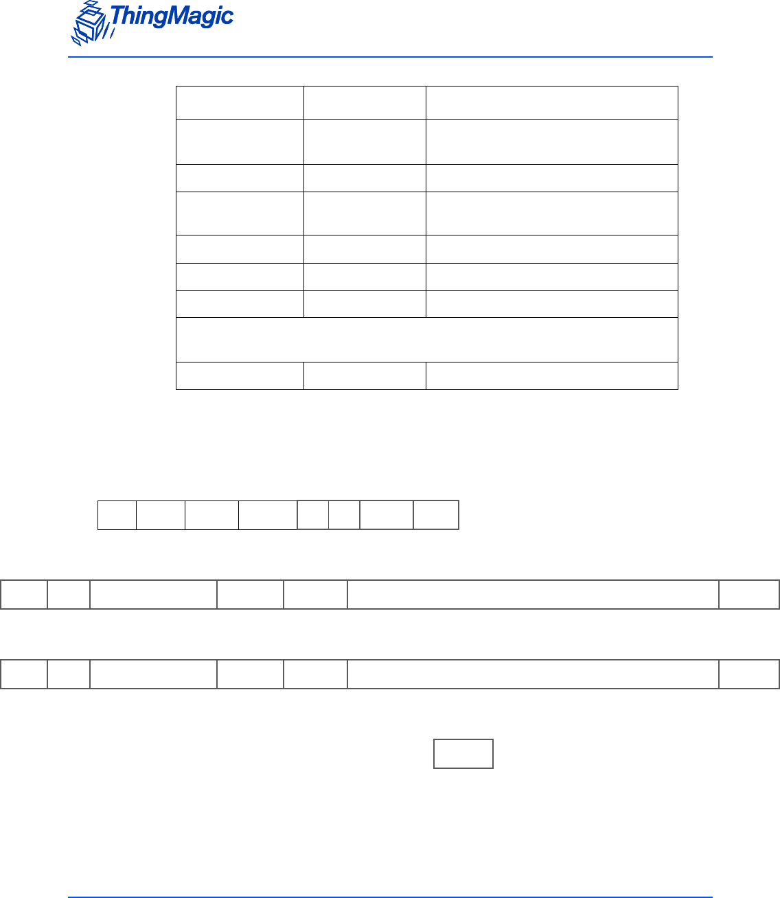
Multi-Protocol Tag Commands
53
Here is an example response to the example request specified above. The response
contains two tags as specified in the Tag Count field each with its EPC info and requested
tag read metadata: Read Count, AntennaID and Timestamp:
RFU12 bytes Reserved for Future Use - ThingMagic
Only
Protocol ID 1 byte Protocol ID of tag read
EPC Length 2 bytes Number of bits in EPC including PC
and CRC bits
PC Word 2 bytes Tag EPC Protocol Control bits
EPC ID N bytes Tag EPC.
Tag CRC 2 bytes Tag EPC CRC
Repeat fields starting at Read Count for remaining tags in message as defined
by Tag Count
CRC 2 bytes Message CRC
1 - Conditionally returned depending on the Metadata Fields specified in the request.
FF 34 29 00 00 00 15 00 02
SOH Length OpCode Status Metadata
Flags Read
Options Tag
Count
22 11 02 50 CE F6 00 80 31 C1 11 11 22 22 33 33 44 44 55 55 66 66 FB 15
Read
Count Ant
ID Timestamp EPC
Length PC Word Tag EPC Tag CRC
OE 11 04 1D 3D 3C 00 80 30 00 05 00 00 00 00 00 00 00 00 00 23 54 4A C8
Read
Count Ant
ID Timestamp EPC
Length PC Word Tag EPC Tag CRC
1A B8
CRC
Field Length Value

Multi-Protocol Tag Commands
54
Clear Tag Buffer (2Ah)
The Clear Tag Buffer command resets the tag buffer. This clears the buffer of any current
tags and reset the read index to 0. A Multi-Protocol Tag Read or Read Tag Multiple
command must be issued to load new tags into the buffer.
If Clear Tag Buffer or Get Tag Buffer is not used after a Multi-Protocol Tag Read to
remove all tags, old tags will be left in the buffer. This means that if tags that have not
been removed from the buffer are read again they will not be added to the buffer as
second time, only their Read Count will be incremented.
Multi-Protocol Tag Read (2Fh)
The Multi-Protocol Tag Read command allows tag reading and inventorying commands to
be performed on tags with different protocols at the same time, using a single command.
This command contains the following request fields:
Multi-Protocol Tag Read Request Fields
FF 00 2A 1D 25
SOH Length OpCode CRC
Field Value Description
TM OpCode 0x2F TM OpCode indicating a multi-protocol opera-
tion.
Timeout [2 bytes] Indicates how long the entire command
should spend attempting the operation, in mil-
liseconds. When TM Option=0x00 the time
gets divided equally across each protocol
specified.
TM Options • 0x00 = Basic Multi-protocol search.
Uses Protocol Bitmask Indicates the operation to perform and addi-
tional fields that will be required.
Command Opcode • 0x00 - reserved
• 0x21 - tag read single
• 0x22 - tag read multiple
Indicates the command that will be performed
for each protocol specified.
Note: Allegro/Title-21 is not supported
with tag read multiple.
Note: Allegro/Title-21 uses Read Request
(28h; C003h) for tag read single.

Multi-Protocol Tag Commands
55
Search Flags [2 bytes - bitwise setting]
Bit 0 = Enable end on tags found
Note: Least Significant Bit = bit 0
Indicates search options. When bit is set = 1
the option will be enabled.
• Bit 0 = 1 (0x01) the search will stop after
the first tag is found, after completing that
protocols entire timeout. i.e. if 4 protocols
are specified with a 100ms timeout and a
tag is found during searching on the
second protocol the remaining protocols
will not be searched and the command will
return after 50ms.
Bit 0 = 0 all protocols will be searched,
using entire timeout.
TM Option = 0x00 Fields - The following field is only used when TM Option = 0x00
Protocol Bitmask
Enables [4 bytes - bitwise setting]
bit 0-3 = not used
bit 4 (0x00000010) = Gen2
bit 5-25 = not used
bit 26 (0x04000000) = eGo
bit 27 (0x08000000) = SeGo
bit 28 (0x10000000) = ATA
bit 29 (0x20000000) = Allegro/Title-21
Note: Least Significant Bit = bit 0
Indicates the protocols to operate on. If the
protocols bit is set to ‘1’ tags of that protocol
will be included in the operation.
OR values together for final setting
Field Value Description

Multi-Protocol Tag Commands
56
Examples
TM Option = 0x00 Request
Response
Note: If a multi-protocol Tag Read Single (command code 0x21) search results in zero tags
found it will not be reported. Only successful searches are reported.
FF ?? 2F ?? ?? 00 ?? ?? ?? ?? ?? ?? ?? ?? ??
SOH Length OpCode Timeout TM
Options Cmd
Opcode Search
Flags Protocol
Bitmask
Enables
CRC
FF ?? 2F ?? ?? 00 ?? ?? ??
SO
HLength OpCod
eStatus TM
Option Cmd
Opcode Search
Flags
?? ?? ?? ?? ?? ....
Protocol
Id1 Protocol
Response
Length
Protocol Response Data
(Includes Status word)
?? ?? ?? ?? ?? ....
Protocol
Id2 Protocol
Response
Length
Protocol Response Data
(Includes Status word)
?? ??
CRC

Allegro/Title-21 Tag Commands
57
Allegro/Title-21 Tag Commands
The Allego/Title-21 tag commands are used to operate on Allegro/Title-21 tags and
perform operations specific to those tags. These commands can only be used when the
Tag Protocol of the reader is set to Allegro/Title-21 (0x001E) using Set Current Tag
Protocol (93h). These commands cannot be run when in Bootloader mode, only in
Application mode.
Allegro/Title-21 Tag Commands
TM
OpCode Operation
Type Allegro/Title-21 Command Transaction
Type Code
0x21 Read ID Single Read Tag ID Single (21h) n/a
0x24 Modify Write Request (24h; A003h) 0xA003
Title-21 ACK Request (24h; C000h) 0xC000
General ACK Request (24h; F00Fh) 0xF00F
0x28 Read Title-21 Read Request (28h; 8000h) 0x8000
Read Request (28h; C003h) 0xC003
Random Number Request (28h; D001h) 0xD001
TDMA Read Request (28h; E003h) 0xE003
0x2C Reset Jump to Reset Request (2Ch; D203h) 0xD203

Allegro/Title-21 Tag Commands
58
Command Syntax
All Allegro/Title-21 tag commands, except Read Tag ID Single, follow the same standard
syntax. The commands are grouped into three ThingMagic M6e-TC OpCodes, as defined
in the Allegro/Title-21 Tag Commands table, indicating their general operation type. In
addition to the 1 of 3 OpCodes each command will have the following fields:
Standard Request Fields
The remaining fields for each command are as defined by Transcore based on the
Transaction Type Code. They occur in the same order and require the same values as
described in the [Transcore doc reference].
Field Value Description
TM OpCode 0x24 TM OpCode
Timeout [2 bytes] Indicates how long the command should spend
attempting the operation, in milliseconds.
TM Options 0x00 Reserved for Future Use.
Transaction Type Code [2 bytes] Allegro/Title-21 code indicating operation to per-
form.

Allegro/Title-21 Tag Commands
59
Read Tag ID Single (21h)
The Read Tag ID Single/Tag Detect command performs a search operation and returns
the first Allegro/Title-21 tag it finds.
Read Tag ID Single Request Fields
Examples
An example, without TM Options, command:
Field Value Description
TM OpCode 0x21 TM OpCode
Timeout [2 bytes] Indicates how long the command should spend attempting
the operation, in milliseconds.
TM Options
Note: This and following
fields are optional.
Bit 4
(LSB=bit 0))• 0 - Metadata flags must not be passed and Meta Data will
not be returned.
• 1 - Metadata flags must be passed and the corresponding
Metadata shall be returned with the tag EPC.
Metadata Flags (to specify
more than one OR the val-
ues together)
0x0000 When no flags are set no meta data will be returned, only the
tag EPC.
0x0001 When bit 0 is set the Read Count will be returned
0x0002 When bit 1 is set the LQI/RSSI will be returned
0x0004 When bit 2 is set the Antenna ID will be returned
0x0008 When bit 3 is set the Frequency will be returned
0x0010 When bit 4 is set the Timestamp will be returned
0x0020 When bit 5 is set the RFU (ThingMagic Only) will be returned
0x0040 When bit 6 is set the Protocol is returned.
FF 02 21 00 FA D6 1B
SOH Length OpCode Time-
out (ms) CRC

Allegro/Title-21 Tag Commands
60
ACK Response
NACK Response
No Response
FF 04 21 00 00 ?? ?? ?? ?? ?? ??
SOH Length OpCode Status Tag ID CRC
FF 00 21 ?? ?? ?? ??
SOH Length OpCode Status CRC
FF 00 21 04 00 B4 83
SOH Length TM
OpCode Status CRC

Allegro/Title-21 Tag Commands
61
Write Request (24h; A003h)
The Write Request command writes data to the specified area of the specified tag. A non-
acknowledge (NACK) error response shall be returned if an invalid password was
included in the request. This command contains the following request fields:
Write Request Fields
Examples
An example command requesting ? be written to tag ? with a User Password = 0x? is:
Field Value Description
TM OpCode 0x24 TM OpCode for tag modification operations
Timeout [2 bytes] Indicates how long the command should spend
attempting the operation, in milliseconds.
TM Options 0x00 Reserved for Future Use.
Transaction Type Code 0xA003 Allegro/Title-21 code indicating operation to per-
form.
Options [1 byte] Command specific options
Page Number [2 bytes] Indicates which page of the tag is to be written to.
Tag ID [4 bytes] Optional, based on value of Options parameter.
Indicates the ID of the tag to operate on.
User Password/
Global Password [4/8 bytes] Optional, based on the value of the Options param-
eter. The password to operation on the tag, if
required.
Page Data Byte Count [1 byte] Indicates the number of data bytes to follow.
Page Data Bytes [N bytes] Data to write to the tag.
FF 0E + N24 ?? ?? 00 A0 03 ?? ?? ??
SOH Length TM
OpCode Timeout
(ms) TM
Option Transaction
Type Code Option Page
Number
?? ?? ?? ?? ?? ?? ?? ?? ?? NN NN ?? ??
Tag ID User/Global
Password Page
Data
Count
Page Data CRC

Allegro/Title-21 Tag Commands
62
ACK Response
NACK Response
No Response
Title-21 ACK Request (24h; C000h)
The Title-21 ACK Request command informs the tag that the reader has successfully
received the tag ID. This will result in the tag not responding to any message whose
transaction type is identical to the most recently received message for a specified period
of 10 seconds, as defined in Title 21 release 1. This command contains the following
request fields:
FF 0C +
(N+1) 24 00 00 00 A0 03 ?? ?? ?? ?? ?? ?? ?? ?? NN NN ?? ??
SOH Length TM
OpCode Status TM
Option Transaction
Type Code Options Tag ID Page
Number Page Data
Count (if
requested)
Page Data CRC
FF 0B 24 04 0A 00 A0 03 ?? ?
??
??
??
??? ??
SOH Length TM
OpCode Status TM
Option Transaction
Type Code Options Tag ID CRC
FF 00 24 04 00 E4 26
SOH Length TM
OpCode Status CRC

Allegro/Title-21 Tag Commands
63
Title-21 ACK Request Fields
Examples
An example command requesting an ACK from tag XXX from reader XXX is:
ACK Response
NACK Response
Field Value Description
TM OpCode 0x24 TM OpCode for tag modification operations
Timeout [2 bytes] Indicates how long the command should spend
attempting the operation, in milliseconds.
TM Options 0x00 Reserved for Future Use.
Transaction Type Code 0xC000 Allegro/Title-21 code indicating operation to per-
form.
Tag ID [4 bytes] Indicates the ID of the tag to operate on.
Reader ID [4 bytes] The reader number for the reader that is acknowl-
edging the receipt of the message.
Transaction Status Code [2 bytes] Code indicating the status of the transaction.
FF 0D 24 ?? ?? 00 C0 00 ?? ?? ?? ?? ?? ?? ?? ?? ?? ?? ?? ??
SOH Length OpCode Time-
out (ms) TM
Option Transaction
Type Code Tag ID Reader ID Transaction
Status Code CRC
FF 03 24 ?? ?? 00 C0 00 ?? ??
SOH Length TM
OpCode Status TM
Option Transaction
Type Code CRC
FF 0B 24 ?? ?? 00 C0 00 ?? ?? ?? ?? ?? ?? ??
SOH Length TM
OpCode Status TM
Option Transaction
Type Code Options Tag ID CRC

Allegro/Title-21 Tag Commands
64
No Response
General ACK Request (24h; F00Fh)
The General ACK Request, or Sign Off Request, command informs the tag that it should
not respond to any commands from the reader for the specified time period. This
command contains the following request fields:
General ACK Request Fields
FF 00 24 04 00 E4 26
SOH Length TM
OpCode Status CRC
Field Value Description
TM OpCode 0x24 TM OpCode for tag modification operations
Timeout [2 bytes] Indicates how long the command should spend
attempting the operation, in milliseconds.
TM Options 0x00 Reserved for Future Use.
Transaction Type Code 0xF00F Allegro/Title-21 code indicating operation to per-
form.
Options [1 byte] Command specific options
Tag ID [4 bytes] Indicates the ID of the tag to operate on.
Time Out [1 byte] Indicates the amount of time the tag shall ignore
commands from the reader, in seconds from 0-127.
Condition Code Bits [1 byte] Represents a condition applicable to a tolling envi-
ronment.
LCD Message Page Pointer [1 byte] Tag memory page where the LCD message to be
displayed is stored in ASCII. Valid range = 0x02 -
0x0F.

Allegro/Title-21 Tag Commands
65
Examples
An example command requesting an ACK from tag XXX from reader XXX is:
ACK Response
NACK Response
No Response
Title-21 Read Request (28h; 8000h)
The Title-21 Read Request command reads the Title-21 tag ID from the tag. This
command contains the following request fields:
FF 0C 24 ?? ?? 00 F0 0F ?? ?? ?? ?? ?? ?? ?? ?? ?? ??
SOH Length OpCode Timeout
(ms) TM
Option Transaction
Type Code Option Tag ID Time
Out Condition
Code LCD
Page
Ptr
CRC
FF 03 24 ?? ?? 00 F0 0F ?? ??
SOH Length TM
OpCode Status TM
Option Transaction
Type Code CRC
FF 0A 24 ?? ?? 00 F0 0F ?? ?
??
??
??
??? ??
SOH Length TM
OpCode Status TM
Option Transaction
Type Code Options Tag ID CRC
FF 00 24 04 00 E4 26
SOH Length TM
OpCode Status CRC

Allegro/Title-21 Tag Commands
66
Title-21 Read Request Fields
Examples
An example command requesting an ACK from tag XXX from reader XXX is:
ACK Response
NACK Response
No Response
Field Value Description
TM OpCode 0x28 TM OpCode for Read operations
Timeout [2 bytes] Indicates how long the command should spend
attempting the operation, in milliseconds.
TM Options 0x00 Reserved for Future Use.
Transaction Type Code 0x8000 Allegro/Title-21 code indicating operation to per-
form.
Agency Code [2 byte] Agency operating the reader installation.
FF 04 28 ?? ?? 00 80 00 ?? ?? ?? ??
SOH Length OpCode Time-
out (ms) TM
Option Transaction
Type Code Agency
Code CRC
FF 0A 28 00 00 00 80 00 ?? ?? ?? ?? ?? ??
SOH Length TM
OpCode Status TM
Option Transaction
Type Code Tag ID CRC
FF 0B 28 ?? ?? 00 80 00 ?? ??
SOH Length TM
OpCode Status TM
Option Transaction
Type Code CRC
FF 00 28 04 00 25 AA
SOH Length TM
OpCode Status CRC

Allegro/Title-21 Tag Commands
67
Read Request (28h; C003h)
The Read Request command reads data from the specified area of the specified tag. This
command contains the following request fields:
Read Request Fields
Examples
An example command format is:
Field Value Description
TM OpCode 0x28 TM OpCode for tag modification operations
Timeout [2 bytes] Indicates how long the command should spend
attempting the operation, in milliseconds.
TM Options 0x00 Reserved for Future Use.
Transaction Type Code 0xC003 Allegro/Title-21 code indicating operation to per-
form.
Options [1 byte] Command specific options.
• Determines whether the AntiPlayBack/BIST
data will be included in the response.
Start Page Number [2 bytes] Indicates which page of the tag is to be read.
Page Count [1 byte] Number of pages to read.
Tag ID [4 bytes] Optional, based on value of Options parameter.
Indicates the ID of the tag to operate on.
User Password/
Global Password [4/8 bytes] Optional, based on the value of the Options param-
eter. The password to operation on the tag, if
required.
FF 0C 28 ?? ?? 00 C0 03 ?? ?? ?? ?? ?? ?? ?? ?? ?? ??
SOH Length TM
OpCode Timeout
(ms) TM
Option Transaction
Type Code Option Page
Number Page
Count Tag ID CRC

Allegro/Title-21 Tag Commands
68
ACK Response
NACK Response
No Response
Random Number Request (28h; D001h)
The Random Number Request command requests a 32-bit random number from the
specified tag which is used in the P/W authentication scheme. This command also
specifies which page is to be read or written to with the encrypted P/W on the next cycle.
This command contains the following request fields:
FF ?? + N28 00 00 00 C0 03 ?? ?? ?? ?? ?? ?? ?? ?? .. .. ?? NN NN ?? ??
SOH Length TM
OpCode Status TM
Option Transaction
Type Code Options Tag ID Page
Number AntiPlay-
Back
(0, 1, 2)
[Based
on
Options]
Page
Count Page Data CRC
FF 0B 28 04 0A 00 C0 03 ?? ?? ?? ?? ?? ?? ??
SOH Length TM
OpCode Status TM
Option Transaction
Type Code Options Tag ID CRC
FF 00 28 04 00 25 AA
SOH Length TM
OpCode Status CRC

Allegro/Title-21 Tag Commands
69
Random Number Request Fields
Examples
An example command:
ACK Response
NACK Response
Field Value Description
TM OpCode 0x28 TM OpCode for tag modification operations
Timeout [2 bytes] Indicates how long the command should spend
attempting the operation, in milliseconds.
TM Options 0x00 Reserved for Future Use.
Transaction Type Code 0xD001 Allegro/Title-21 code indicating operation to per-
form.
Options [1 byte] Command specific options
Tag ID [4 bytes] Indicates the ID of the tag to operate on.
Page Number [2 bytes] Species which page is to be operated on in the next
transaction.
Next Command [2 bytes] Specifies which command the reader will be send-
ing ot the tag on the next transaction, by Transac-
tion Type Code. Only Read and Write Request
commands are supported.
FF 0C 28 ?? ?? 00 D0 01 ?? ?
??
??
??
??? ?? ?? ?? ?? ??
SOH Length TM
OpCode Timeout
(ms) TM
Option Transaction
Type Code Option Tag ID Page
Number Next Com-
mand CRC
FF ?? + N28 00 00 00 D0 01 ?? ?? ?? ?? ?? ?? ?? ??
SOH Length TM
OpCode Status TM
Option Transaction
Type Code Random Number ATA
Page
Number
CRC
FF 0B 28 04 0A 00 D0 01 ?? ?? ?? ?? ?? ?? ??
SOH Length TM
OpCode Status TM
Option Transaction
Type Code Options Tag ID CRC

Allegro/Title-21 Tag Commands
70
No Response
TDMA Read Request (28h; E003h)
The TDMA Read Request command returns the tag ID from the first tag to respond
only. This command contains the following request fields:
TDMA Read Request Fields
Examples
An example command is:
ACK Response
FF 00 28 04 00 25 AA
SOH Length TM
OpCode Status CRC
Field Value Description
TM OpCode 0x28 TM OpCode for tag modification operations
Timeout [2 bytes] Indicates how long the command should spend
attempting the operation, in milliseconds.
TM Options 0x00 Reserved for Future Use.
Transaction Type Code 0xE003 Allegro/Title-21 code indicating operation to per-
form.
Options [1 byte] Command specific options
Number of Slots [1 byte] Specifies how many slots are available for the tags
to choose from. Valid values from 0x01-0xFF
FF ?? 28 ?? ?? 00 E0 03 ?? ?? ?? ??
SOH Length TM
OpCode Timeout
(ms) TM
Option Transaction
Type Code Option Number
of Slots CRC
FF 0B 28 00 00 00 E0 03 ?? ?? ?? ?? ?? ?? ??
SOH Length TM
OpCode Status TM
Option Transaction
Type Code Option Tag ID CRC

Allegro/Title-21 Tag Commands
71
NACK Response
No Response
Jump to Reset Request (2Ch; D203h)
The Jump to Reset Request command requests the tag perform a hard reset. The reset
will occur the same as a hardware reset and the decision is made by the tag to perform a
cold boot or a warm boot by analyzing the first 32 bits of page 0000 in the tag. If the bits
are all 0s or all 1s, then a cold boot will be performed, otherwise a warm boot will occur.
This command contains the following request fields:
Jump to Reset Request Fields
Examples
An example command is:
FF 0B 28 04 0A 00 E0 03 ?? ?? ?? ?? ?? ?? ??
SOH Length TM
OpCode Status TM
Option Transaction
Type Code Options Tag ID CRC
FF 00 28 04 00 25 AA
SOH Length TM
OpCode Status CRC
Field Value Description
TM OpCode 0x2C TM OpCode for tag modification operations
Timeout [2 bytes] Indicates how long the command should spend
attempting the operation, in milliseconds.
TM Options 0x00 Reserved for Future Use.
Transaction Type Code 0xD203 Allegro/Title-21 code indicating operation to per-
form.
FF 05 2C ?? ?? 00 D2 03 ?? ??
SOH Length TM
OpCode Timeout
(ms) TM
Option Transaction
Type Code CRC

Allegro/Title-21 Tag Commands
72
NACK Response
FF 00 2C 04 00 65 2E
SOH Length TM
OpCode Status CRC

eGo/SeGo Tag Command Set
73
eGo/SeGo Tag Command Set
The eGo/SeGo tag commands are used to operate oneGo/SeGo tags and perform
operations specific to those tags. These commands can only be used when the Tag
Protocol of the reader is set to eGo/SeGo (0x001B or 0x001C) using Set Current Tag
Protocol (93h). These commands cannot be run when in Bootloader mode, only in
Application mode.
eGo/SeGo Tag Commands
OpCode Command Name
0x21 Read Tag ID Single (21h)
0x22 Read Tag ID Multiple (22h)
0x24 Write Tag Data (24h)
0x25 Lock Tag Data (25h)
0x28 Read Tag Data (28h)
0x2D Custom Tag Operations (2Dh)

eGo/SeGo Tag Command Set
74
Command Syntax
All eGo/SeGo tag commands follow the same standard syntax. Each command has the
following common fields followed by additional fields required for the specific operation
being performed:
Standard Request Fields
Group Select Options
The following table defines the Command Type values to use for the desired Group
Select Option when performing a Read Tag ID Single (21h), Read Tag ID Multiple (22h) or
Write Tag Data (24h). The Group Select Option along with the Select Fields (Byte Address,
Byte Mask and Word Data) determine which tags will respond to the specified query.
Group Select Options
Field Value Description
TM OpCode 0xXX TM OpCode as defined in eGo/SeGo Tag Com-
mands
Timeout [2 bytes] Indicates how long the command should spend
attempting the operation, in milliseconds.
TM Options 0x01 Must be set to 0x01, indicating Command Type and
eGo/SeGo specific fields to follow.
Command Type [1 byte] Depending on the operation indicates either the
Group Select Options to apply or a specific sub-
command.
Command
Type Value Group Select Option Tag Selection Behavior
0x00 GROUP_SELECT_EQ All tags in the field whose data EQUALS the
specified Select Fields will respond.
0x01 GROUP_SELECT_NE All tags in the field whose data does NOT
EQUAL the specified Select Fields will
respond.
0X02 GROUP_SELECT_GT All tags in the field whose data is GREATER
THAN the specified Select Fields will
respond.

eGo/SeGo Tag Command Set
75
0X03 GROUP_SELECT_LT All tags in the field whose data is LESS
THAN the specified Select Fields will
respond.
0X04 GROUP_UNSELECT_EQ All tags except those in the field whose data
EQUALS the specified Select Fields will
respond.
0X05 GROUP_UNSELECT_NE All tags except those in the field whose data
does NOT EQUAL the specified Select Fields
will respond.
0X06 GROUP_UNSELECT_GT All tags except those in the field whose data is
GREATER THAN the specified Select Fields
will respond.
0X07 GROUP_UNSELECT_LT All tags except those in the field whose data is
LESS THAN the specified Select Fields will
respond.
Command
Type Value Group Select Option Tag Selection Behavior

eGo/SeGo Tag Command Set
76
Read Tag ID Single (21h)
The Read Tag ID Single command executes a query for tags matching the criteria
specified by the Command Type and subsequent fields and returns the first tag found.
Read Tag ID Single Request Fields
Field Value Description
TM OpCode 0x21 TM OpCode
Timeout [2 bytes] Indicates how long the command should spend attempt-
ing the operation, in milliseconds.
TM Options Bit 0 • 1 - Indicates Command Type and additional fields to
follow.
Bit 4
(LSB=bit 0))• 0 - Metadata flags must not be passed and Meta
Data will not be returned.
• 1 - Metadata flags must be passed and the
corresponding Metadata shall be returned with the
tag EPC.
Metadata Flags (to specify
more than one OR the val-
ues together)
0x0000 When no flags are set no meta data will be returned,
only the tag EPC (including PC bits and tag CRC)
0x0001 When bit 0 is set the Read Count will be returned
0x0002 When bit 1 is set the LQI/RSSI will be returned
0x0004 When bit 2 is set the Antenna ID will be returned
0x0008 When bit 3 is set the Frequency will be returned
0x0010 When bit 4 is set the Timestamp will be returned
0x0020 When bit 5 is set the RFU (ThingMagic Only) will be
returned
0x0040 When bit 6 is set the Protocol is returned.
Command Type [1 byte] Indicates the Group Select criteria to apply as defined in
Group Select Options.
Byte Address [1 byte]
Byte Mask [1 byte]
Word Data [8 bytes]

eGo/SeGo Tag Command Set
77
Examples
An example command:
ACK Response
NACK Response
No Response
Read Tag ID Multiple (22h)
The Read Tag ID Multiple command performs a search for the specified period of time
then returns the number of tags that have been found. Afterwards, multiple Get Tag Buffer
(29h) commands can be sent to receive the found tag IDs.
Standard Syntax
The search criteria for the Standard Syntax which allows control over the select criteria is
specified by the Command Type and subsequent fields.
FF 0E 21 ?? ?? 01 00 ?? ?? ?? ?? ?? ?? ?? ?? ?? ?? ?? ??
SOH Length OpCode Time-
out (ms) TM
Option Command
Type Byte
Address Byte
Mask Word Data CRC
FF 0C 21 ?? ?? 01 ?? ?? ?? ?? ?? ?? ?? ?? ?? ?? ?? ?? ??
SOH Length OpCode Status TM
Option Command
Type Tag Data CRC
FF 02 21 ?? ?? 01 ?? ?? ??
SOH Length OpCode Status TM
Option Command
Type CRC
FF 00 21 04 00 B4 83
SOH Length TM
OpCode Status CRC

eGo/SeGo Tag Command Set
78
Read Tag ID Multiple Request Fields
Examples
An example command requesting :
ACK Response
NACK Response
Field Value Description
TM OpCode 0x22 TM OpCode
TM Options 0x01 Indicates Command Type and additional fields to follow.
Search Flags 0x0000 Reserved for Future Use.
Timeout [2 bytes] Indicates how long the command should spend attempt-
ing the operation, in milliseconds.
Command Type [1 byte] Indicates the Group Select criteria to apply as defined in
Group Select Options.
Byte Address [1 byte]
Byte Mask [1 byte]
Word Data [8 bytes]
FF 10 22 01 00 00 ?? ?? 00 ?? ?? ?? ?? ?? ?? ?? ?? ?? ?? ?? ??
SOH Length OpCode TM
Option Search
Flags Timeout
(ms) Command
Type Byte
Address Byte
Mask Word Data CRC
FF ?? 22 ?? ?? 01 00 00 ?? ?? ?? ?? ??
SOH Length OpCode Status TM
Option Search
Flags Command
Type Tag IDs
Detected CRC
FF 02 22 ?? ?? 01 ?? ?? ??
SOH Length OpCode Status TM
Option Command
Type CRC

eGo/SeGo Tag Command Set
79
No Response
Minimal Syntax
The Read Tag ID Multiple command can also be used in a reduced syntax format. In
this case only the Timeout is specified. This syntax performs a search for the specified
period of time with no selection criteria, returning the number of tags that have been
found.
Example
An example response is as follows:
Write Tag Data (24h)
The Write Tag Data command writes data to a tag. The tag to write to, the location and
the data to write are specified in the fields as defined below:
FF 00 22 04 00 84 E0
SOH Length TM
OpCode Status CRC
FF 02 22 03 E8 E5 6A
SOH Length OpCode Timeout (ms) CRC
FF 01 22 00 00 02 46 BA
SOH Length OpCode Status # Tag IDs Found CRC

eGo/SeGo Tag Command Set
80
Write Tag Data Request Fields
Field Value Description
TM OpCode 0x24 TM OpCode
Timeout [2 bytes] Indicates how long the command should spend attempt-
ing the operation, in milliseconds.
TM Options
Note: TM Options field
combines bits 0-4
indicating the
verification method
and bits 5 & 6 for
authentication
information. For
the final TM
Options setting,
the two “fields”
should be OR’d.
[1 byte]
excluding bits
5 & 6
(LSB = bit 0)
• 0x00 = A READ is executed after the WRITE has
reported success for verification. Lock if requested.
Note: When 0x00 the Command Type is implicity =
0x0D and the Command Type 1 byte field
should be removed from the request
command.
• 0x01 = No verification is executed after WRITE reports
success.
• 0x02 = A READ_VERIFY is executed after the WRITE
reports success for verification.
• 0x03 = Only used with Command Type = 0x0E or
0x93. Indicates extra Select fields will be specified.
bits 5 & 6
(LSB = bit 0) Specify authentication method to use:
• 0x00 = authentication is disabled and Key values must
not be passed.
• 0x20 = RFU
• 0x40 = authentication is enabled and Key values must
be passed.
• 0x60 = RFU
Command Type
Note: If TM Options bits
0-4=0 then the
Command Type is
implicity = 0x0D
and this byte
should not be
specified in the
request command.
0x0D Indicates the eGo/SeGo Write by Byte operation will be
used.
0x8D Indicates the eGo/SeGo Write by Page operation will be
used
0x0E Indicates the eGo/SeGo Write Multiple operation will be
used.
0x93 Indicates the eGo/SeGo Streamlined Group Select
Equal Page Write operation will be used.

eGo/SeGo Tag Command Set
81
Lock [1 byte] • 0x00 = no lock
• 0x01 = lock the data specified by Write Data
Write by Page won’t lock if authentication information is
not specified.
Write multiple won’t lock
Write Address [1|4byte] Indicates the start address of tag memory to be written:
• 4 Byte Address when TM Option = 0xX0
• 1 Byte Address otherwise
Select Command Type [1 byte] Indicates the Group Select criteria to apply as defined in
Group Select Options.
Only passed when TM Option=0x03.
For Command Type = 0x0E, indicates Select Type
For Command Type = 0x93, RFU
Select Address [1 byte] Only passed when TM Option=0x03.
Select Mask [1 byte] Only passed when TM Option=0x03.
For Command Type = 0x0E, indicates Select Mask
For Command Type = 0x93, RFU
Tag ID | Select Data [8 bytes] When:
• Command Type = 0x0D, 0x0E or 0x8D:
8 bytes = Tag ID
• Command Type = 0x93 AND TM Options=0x03:
[1 byte] = Select Data
[7 bytes] = RFU
• Command Type = 0x93 AND TM Options=0x01 or
0x02
[1 byte] = Select Address
[1 byte] = Select Data
[6 bytes] = RFU
Write Data [1|8 byte] Indicates the data to be written to the specified tag starting
at the specified address.
• 1 Byte when Command=0x0D and 0x0E
• 8 Bytes (1 page) when Command=0x8D and 0x93
Key Address [1 byte] Only passed when authentication enabled in TM Options.
Key Length in Bytes [1 byte] Only passed when authentication enabled in TM Options.
Field Value Description

eGo/SeGo Tag Command Set
82
Examples
An example command requesting :
ACK Response
When Command Type = 0x0D or 0x0E,
When Command Type = 0x8D
When Command Type = 0x93
Note
ACK Status will be:
0x0000 FAULT_SUCCESS_CODE
0x0403 FAULT_WRITE_PASSED_LOCKED_FAILED
Key [0-N bytes] Only passed when authentication enabled in TM Options.
Note: Value passed with MSB first.
FF 0F 24 ?? ?? 01 0D ?? ?? ?? ?? ?? ?? ?? ?? ?? ?? ?? ?? ??
SOH Length OpCode Timeout
(ms) TM
Option Command
Type Lock Write
Address Tag ID Write
Data CRC
FF 03 24 ?? ?? ?? 0D | OE ?? ?? ??
SOH Length OpCode Status TM
Option Command
Type Verified
Write Data CRC
FF 0A 24 ?? ?? ?? 8D ?? ?? ?? ??
?? ?? ?? ?? ?? ??
SOH Length OpCode Status TM
Option Command
Type Verified Write
Data CRC
FF 13 24 ?? ?? ?? 93 ?? ?? ?? ?? ??
?? ?? ?? ?? ?? ?? ?? ??
?? ?? ?? ?? ?? ??
SOH Length OpCode Status TM
Option Command
Type Tag ID
Length Tag ID (length
defined by ID
Length)
Verified Write
Data CRC
Field Value Description

eGo/SeGo Tag Command Set
83
NACK Response
No Response
Lock Tag Data (25h)
The Lock Tag Data command locks and unlocks a tag’s memory locations. The tag to
(un)lock and memory location to be (un)locked are specified in the fields as defined
below:
Lock Tag Data Request Fields
FF 02 24 ?? ?? 01 0D ?? ??
SOH Length OpCode Status TM
Option Command
Type CRC
FF 00 24 04 00 E4 26
SOH Length TM
OpCode Status CRC
Field Value Description
TM OpCode 0x25 TM OpCode
Timeout [2 bytes] Indicates how long the command should spend attempt-
ing the operation, in milliseconds.
TM Options
Note: TM Options field
combines bit 0
indicating general
processing
information and
bits 5 & 6
indicating
authentication
method. For the
final TM Options
setting, the two
“fields” should be
OR’d.
0x01 Indicates Command Type and additional fields to follow.
bits 5 & 6
(LSB = bit 0) Specify authentication method to use:
• 0x00 = authentication is disabled and Key values must
not be passed.
• 0x20 = RFU
• 0x40 = authentication is enabled and Key values must
be passed.
• 0x60 = RFU

eGo/SeGo Tag Command Set
84
Examples
An example command requesting :
Command Type 0x00 Performs a QueryLock, immediate followed by an UnLock
0x01 Performs a QueryLock, immediate followed by a Lock
0x0F LockByte operation. Performs QLock/Lock/QLock
0x10 UnLock Byte. Performs QLock/UnLock/QLock
0x11 QueryLock
0x8F Lock Page. Performs QLock/Lock/QLock
0x90 UnLock Page. Performs QLock/UnLock/QLock
Lock Address [1 byte] Indicates the address of tag memory to be (un)locked.
Tag ID [8 byte] Indicates the Tag ID of the tag to be (un)locked.
Key Address [1 byte] Only passed when authentication enabled in TM Options.
Key Length in Bytes [1 byte] Only passed when authentication enabled in TM Options.
Key [0-N bytes] Only passed when authentication enabled in TM Options.
Note: Value passed with MSB first.
FF 0D 25 ?? ?? 01 0F ?? ?? ?? ?? ?? ?? ?? ?? ?? ?? ??
SOH Length OpCode Timeout
(ms) TM
Option Command
Type Lock
Address Tag ID CRC
Field Value Description

eGo/SeGo Tag Command Set
85
ACK Response
When Command Type = 0x00 or 0x01
When Command Type = all others
NACK Response
No Response
Note
For eGo Plus tags a key must be provided for lock/unlock operations. If a
key is not provided then the tag will not respond. In that case a
status=0x0400 is the expected command response.
Read Tag Data (28h)
The Read Tag Data command reads data from a tag. The tag to read from and the
location to read the data from are specified in the fields as defined below:
FF 03 25 ?? ?? ?? 00 | 01 ?? ?? ??
SOH Length OpCode Status TM
Option Command
Type (Un)Lock
Response CRC
FF 04 25 ?? ?? ?? ?? ?? ?? ?? ??
SOH Length OpCode Status TM
Option Command
Type Lock
Response Query Lock
Response CRC
FF 03 25 ?? ?? ?? ?? ?? ?? ??
SOH Length OpCode Status TM
Option Command
Type Lock
Response CRC
FF 00 25 04 00 F4 07
SOH Length TM
OpCode Status CRC

eGo/SeGo Tag Command Set
86
Read Tag Data Request Fields
Field Value Description
TM OpCode 0x28 TM OpCode
Timeout [2 bytes] Indicates how long the command should spend attempting the
operation, in milliseconds.
TM Options
Note: TM Options field
combines bits 0-4
indicating general
processing
information and
bits 5 & 6
indicating
authentication
method. For the
final TM Options
setting, the two
“fields” should be
OR’d.
[1 byte] Indicates Command Type and additional fields to follow:
• 0x01 = For Standard Read Operations
bits 5 & 6
(LSB = bit 0) Specify authentication method to use:
• 0x00 = authentication is disabled and Key values must not
be passed.
• 0x20 = RFU
• 0x40 = authentication is enabled and Key values must be
passed.
• 0x60 = RFU
Command Type 0x0C eGo/SeGo Read, or Protected Read
0x0B eGo/SeGo Data_Read
0x12 eGo/SeGo Read_Verify
Note: Requires a Write to occur immediately before.
0x80 eGo/SeGo Streamline_Group_Select_Equal_Page_Read
Note: Only works with eGo Plus tags.
0x92 eGo/SeGo Read_Verify_Page
Note: Requires a Write to occur immediately before.
RFU [1 byte] Reserved for Future Use
Read Byte Count [1 byte] Number of bytes starting at Read Address to read. Can
request 1 to 8 bytes.
Read Address [1 byte] Indicates the start address of tag memory to be read.

eGo/SeGo Tag Command Set
87
Examples
An example command requesting :
ACK Response
When Command Type = 0x80
Tag ID | Select Data [8 bytes] When:
• Command Type = 0x0B, 0x0C, 0x12 or 0x92:
8 bytes = Tag ID
• Command Type = 0x80
[1 byte] = Select Address
[1 byte] = Select Data
[6 bytes] = RFU
Key Address [1 byte] Only passed when authentication enabled by TM Options.
Key Length in Bytes [1 byte] Only passed when authentication enabled by TM Options.
Key [0-N bytes] Only passed when authentication enabled by TM Options.
Note: Value passed with MSB first.
FF 0F 28 ?? ?? 01 0C ?? ?? ?? ?? ?? ?? ?? ?? ?? ?? ?? ?? ??
SOH Length OpCode Timeout
(ms) TM
Option Command
Type RFU Read
Byte
Count
Read
Address Tag ID CRC
FF ?? 28 ?? ?? 01 0C ?? ?? ??
SOH Length OpCode Status TM
Option Command
Type Read
Data CRC
FF ?? 28 ?? ?? ?? 80 ?? ?? ?? ?? ??
?? ?? ?? ?? ?? ?? ?? ??
?? ?? ?? ?? ?? ??
SOH Length OpCode Status TM
Option Command
Type Tag ID
Length Tag ID (length
defined by ID
Length)
Read Data CRC
Field Value Description

eGo/SeGo Tag Command Set
88
NACK Response
No Response
Custom Tag Operations (2Dh)
The Custom Tag Operations command provides access to several eGo/SeGo tag
specific operations including: Fail, Success, Initialize, Resend, Read_All_Data,
Read_All_Lock, and RN_Request. The operation to be performed is indicated by the
Command Type field:
Custom Tag Operations Request Fields
FF 02 28 ?? ?? 01 0C ?? ??
SOH Length OpCode Status TM
Option Command
Type CRC
FF 00 28 04 00 25 AA
SOH Length TM
OpCode Status CRC
Field Value Description
TM OpCode 0x2D TM OpCode
Timeout [2 bytes] Indicates how long the command should spend
attempting the operation, in milliseconds.
TM Options 0x01 Indicates Command Type to follow.
Command Type 0x08 Fail
0x09 Success
0x0A Initialize
0x15 Resend
0x81 RN Request
0x82 Tag Authentication. When specified the Key fields
also must be passed.
0x83 Mutual Authentication. When specified the Key
fields also must be passed.

eGo/SeGo Tag Command Set
89
Examples
An example command requesting :
ACK Response
NACK Response
No Response
Key Address [1 byte] Only passed when Command=0x82 or 0x83.
Key Length in Bytes [1 byte] Only passed when Command=0x82 or 0x83.
Key [0-N bytes] Only passed when Command=0x82 or 0x83.
Note: Value passed with MSB first.
FF 04 2D ?? ?? 01 0C ?? ??
SOH Length OpCode Timeout
(ms) TM
Option Command
Type CRC
FF 05 2D ?? ?? 01 0C ?? ... NN ?? ??
SOH Length OpCode Status TM
Option Command
Type Tag Da ta
(0-N based on
Command Type)
CRC
FF 02 2D ?? ?? 01 ?? ?? ??
SOH Length OpCode Status TM
Option Command
Type CRC
FF 00 2D 04 00 75 0F
SOH Length TM
OpCode Status CRC
Field Value Description

eGo/SeGo Tag Command Set
90

ATA Tag Command Set
91
ATA Tag Command Set
The ATA tag commands are used to perform operations specific to ATA tags. These
commands can only be used when the Tag Protocol of the reader is set to ATA (0x001D)
using Set Current Tag Protocol (93h). These commands cannot be run when in Bootloader
mode, only in Application mode.
ATA Tag Commands
OpCode Command Name
0x21 Read Tag ID Single (21h)
0x22 Read Tag ID Multiple (22h) [Not yet
Implemented]

ATA Tag Command Set
92
Command Syntax
All ATA tag commands follow the same standard syntax. Each command has the
following common fields followed by additional fields required for the specific operation
being performed:
Standard Request Fields
Field Value Description
TM OpCode 0xXX TM OpCode as defined in ATA Tag Commands
Timeout [2 bytes] Indicates how long the command should spend
attempting the operation, in milliseconds.

ATA Tag Command Set
93
Read Tag ID Single (21h)
The Read Tag ID Single/Tag Detect command performs a search operation and returns
the first ATA tag it finds.
Read Tag ID Single Request Fields
Examples
An example, without TM Options, command:
Field Value Description
TM OpCode 0x21 TM OpCode
Timeout [2 bytes] Indicates how long the command should spend attempting
the operation, in milliseconds.
TM Options
Note: This and following
fields are optional.
Bit 4
(LSB=bit 0))• 0 - Metadata flags must not be passed and Meta Data will
not be returned.
• 1 - Metadata flags must be passed and the corresponding
Metadata shall be returned with the tag EPC.
Metadata Flags (to specify
more than one OR the val-
ues together)
0x0000 When no flags are set no meta data will be returned, only the
tag EPC.
0x0001 When bit 0 is set the Read Count will be returned
0x0002 When bit 1 is set the LQI/RSSI will be returned
0x0004 When bit 2 is set the Antenna ID will be returned
0x0008 When bit 3 is set the Frequency will be returned
0x0010 When bit 4 is set the Timestamp will be returned
0x0020 When bit 5 is set the RFU (ThingMagic Only) will be returned
0x0040 When bit 6 is set the Protocol is returned.
FF 02 21 ?? ?? ?? ??
SOH Length OpCode Time-
out (ms) CRC

ATA Tag Command Set
94
ACK Response
NACK Response
No Response
Read Tag ID Multiple (22h)
[Not yet implemented]
FF 0A 21 ?? ?? ?? ?? ?? ?? ?? ?? ?? ?? ?? ??
SOH Length OpCode Status Tag ID CRC
FF 00 21 ?? ?? ?? ??
SOH Length OpCode Status CRC
FF 00 21 04 00 B4 83
SOH Length TM
OpCode Status CRC

Gen2 Tag Commands
95
Gen2 Tag Commands
The Gen2 tag commands are used to operate on Gen2 tags and perform operations
specific to those tags. These commands can only be used when the Tag Protocol of the
reader is set to Gen2 (0x0005) using Set Current Tag Protocol (93h). These commands
cannot be run when in Bootloader mode, only in Application mode.
Gen2 Tag Commands
OpCode Command Name Arguments Return BL App
0x21 Read Tag Single (21h) Timeout (ms) Tag ID N Y
0x22 Read Tag Multiple (22h) Timeout (ms),
Antennas Flag Multiple Tag
IDs NY
0x23 Write Tag EPC (23h) Timeout (ms), lock
bit, password, tag
ID
None N Y
0x24 Write Tag Data (24h) Timeout (ms), lock
bit, address, data None N Y
0x25 Lock Tag (25h) Timeout (ms), proto-
col specific data None N Y
0x26 Kill Tag (26h) Timeout (ms), proto-
col specific data None N Y
0x28 Read Tag Data (28h) Timeout (ms),
Address, Tag ID Tag data N Y
0x29 Get Tag Buffer (29h) various various N Y
0x2A Clear Tag Buffer (2Ah) none none N Y
0x2D Gen2 Tag Specific (2Dh) Timeout (ms), Chip
Type, option, Kill
password, Access
password, Tag ID
none N Y
0x2E Erase Block Tag Specific
(2Eh)
Timeout (ms), chip
type, option addr,
mem bank, number
of words to erase
none N Y

Gen2 Tag Commands
96
Tag Singulation/Select Functionality
Many of the Gen2 tag commands now support the ability to singulate a specific tag or
inventory only tags matching a defined criteria, i.e. matching on values in the EPC, TID
and User Memory banks.
Select Algorithm and Parameters
The algorithm used to perform a Gen2 Select and its impact on subsequent Gen2 Query
operations on a population of tags is determined by several user defined settings which
either correspond directly to or are used to determine the various Gen2 Select and Query
parameters as defined by the EPCGlobal Gen2 v1.2 Specification. The current user
controlled options are:
Gen2 Session (User Controlled)
This setting determines which tag inventory flag is altered when a tag responds to a Gen2
Query (each flag has a unique persistence profile, as defined by the Gen2 Specification).
The value of Gen2 Session is set using the Set Protocol Configuration (9Bh) command.
The supported values are 0, 1, 2, or 3.
Select Invert (User Controlled)
This setting is used to determine the Gen2 Action value sent in the Gen2 Select
command. The value of Select Invert is defined using bit 3 of the Select Option field in the
Tag Singulation Fields. The supported values are:
0 (False) - Tags which match the Select criteria are to respond. Set Gen2
Action=0.
1 (True) - Tags which DO NOT match the Select criteria are to respond. Set Gen2
Action=4.
The settings specified for Gen2 Session and Select Invert determine the settings within
the Select command which is sent before the corresponding Gen2 Query and the settings
in the subsequent Gen2 Query(s). These implicit settings used by the Gen2 Select are:
Gen2 Action (defined by Select Invert)
This parameter can be one of 8 values, as defined by the Gen2 specification, which
determine which of 4 possible flag actions (assert, de-assert, negate, or leave alone) will
be done if the criteria matches and, similarly, which of the 4 possible flag actions will be
done if the criteria does not match. Only two values are currently used:

Gen2 Tag Commands
97
0 - Assert (or put in state “A” for inventory flags) the target flag if there IS a match;
de-assert (or put in state “B” for inventory flags) the target flag if there IS
NOT a match.
4 - Assert (or put in state “A” for inventory flags) the target flag if there IS NOT a
match; de-assert (or put in state “B” for inventory flags) the target flag if
there IS a match
Gen2 Target (Static)
This setting determines which inventory flag or SL flag is going to have its state
determined by the matching algorithm. Currently always set to ‘4’, indicating the Gen2
Select command modifies a tag’s SL flag.
The following table defines the currently supported User Settings and the resulting
behavior of the Gen2 Select and Gen2 Query:
Gen2 Select and Query Behavior
Select Process
The following defines how the Select process works when attempting to select tags that
match a defined criteria:
User Settings Select Behavior Query Behavior Comments
• Gen2 Session =
0,1,2,3
• Invert = 0
Gen2 Select Settings:
• Target = 4
• Action = 0
If tags match the criteria,
put their SL flag in the
‘Assert’ state; and SL of
non-matching tags into the
‘De-assert’ state.
Gen2 Query Settings:
• SEL = 3
• Target = “A”
• Session = [User
Defined]
Ask tags to respond if their
SL flag is in the ‘Assert’
state and their session
appropriate inventory flag is
in the ‘A’ state. Once a tag
responds, it puts the inven-
tory flag in the ‘B’ state, pre-
venting further matches
until the inventory flag’s
Flag Persistence Rules
returns it to the ‘A’ state.
Tag state persistence
before a Query is based
on SL flag persistence;
Tag state persistence
after a Query is based on
inventory flag corre-
sponding to the Session
used.
• Gen2 Session =
0,1,2,3
• Invert = 1
Gen2 Select Settings:
• Target = 4
• Action = 4
If tags match the criteria,
put their SL flag in the ‘De-
assert’ state; and SL of
non-matching tages into the
‘Assert’ state.

Gen2 Tag Commands
98
1. The Reader issues a Select containing the desired tag memory values and
instructions for the tag to assert if its contents matches that specified in the request
(and, conversely, de-assert the SL flag if it does not match) as defined by the Tag
Singulation Fields. The de-assert will generally have no effect because the de-
asserted state is the default, but is helpful if tags still have their SL flag asserted from
a previous Select.
– Tags that are selected, at this point, are not selected within a specific Session. The
persistence of their state depends entirely on that of the SL flag.
2. A Query is issued which specifies the flag settings which must match before a tag will
respond:
– The SL flag must be asserted
– The Session flag for session 0, 1, 2, or 3 (specific Session value is in the Query
and depends on the reader’s Session setting) must be ‘A’ (the default value).
3. Matching tags will respond to the Query, but after responding, will change their own
state in the following way:
– The Inventory flag corresponding to the Session specified in the Query will be
changed to the ‘B’ state.
– The SL flag will remain asserted (per its ongoing Flag Persistence Rules)
4. If subsequent indentical Queries are issued (identical to the first), this tag will remain
silent until the Flag Persistence Rules for the inventory flag that was put into the ‘B’
state cause the flag to fall back into the ‘A’ state. At that point, the tag will respond
again (assuming that the persistence rules of the SL flag are still keeping it in the
‘assert’ state).
Note
A search with Invert=1 specified will perform the same steps except in step
1 the tag will “de-assert if its contents matches that specified in the request
(and, conversely, assert the SL flag if it does not match) as defined by the
Tag Singulation Fields.”
Note
A Select will be performed once per antenna when Select is specified during
a Read Tag Multiple (22h) with multiple antennas configured.
Flag Persistence Rules
Session 0
Keeps state as long as tag is energized

Gen2 Tag Commands
99
Returns to default state as soon as the tag is no longer energized
Its state will often get reset during the course of executing a single command, for
example, between inventory rounds, or when there is a frequency hop, or when a new
antenna is selected during a Read Tag Multiple search. the result is that when the session
is set to ‘0’, all tags will respond to every appropriate Query, considerably lengthening the
time to inventory a large population of tags. Session 0 is typically used for operations
where a single tag is expected to be in the field, for example, printers.
Session 1
Keeps its state between 0.5 and 5 seconds, regardless of whether the tag is
energized or not.
The intent is that when the session is set to 1 the tag will respond to an appropriate Query
immediately, and then respond periodically if the Query is repeated by the reader. This
allows a larger population of tags to be reliable read. Session 1 is typically used in
applications where a large population of tags is being continuously inventoried allowing
for it to be determined when tags enter and leave the field.
Session 2, 3 and SL Flags
Keeps state as long as the tag is energized.
Keeps its state for at least 2 seconds after the tag is no longer energized and will
refresh its state if the tag is re-energized during that period.
The intent is that when the session is set to ‘2’ or ‘3’ a tag will only respond once to an
appropriate Query, then remain silent as the Query is repeated by the reader to elicit
responses from other tags. Typically used in operations when you are performing an
action on tag or population of tags which you do not want/need repeated.
Operations supporting Tag Singulation/Select
The commands currently supporting tag singulation through Select are:
Read Tag Single (21h)
Read Tag Multiple (22h)
Write Tag Data (24h)
Lock Tag (25h)
Kill Tag (26h)

Gen2 Tag Commands
100
Read Tag Data (28h)
The following fields apply to all the specified commands. Please check each command for
exact order, and any exceptions, as they may not all correspond with the order below.
Tag Singulation Fields
Field Values Description
Select Option 0x00 Select functionality is disabled. First tag found will be the tag
operated on. No other Tag Singulation Fields should be
specified. Option field must always be specified.
0x01 Select on the value of the EPC. Requires all fields except
the Select Address field.
0x02 Select on contents of TID memory bank (Gen2 bank 0x02).
Requires all fields.
0x03 Select on contents of User Memory memory bank (Gen2
bank 0x03). Requires all fields.
0x04 Select on contents of the EPC memory bank (Gen2 bank
0x01). Requires all fields.
0x08 Sets Invert Flag. This results in tags NOT matching the
specified Tag Singulation Fields will be returned, as defined
in Select Algorithm and Parameters.
Select Address 4 bytes Contains the offset, in bits, within the memory bank, speci-
fied by the Option value, at which the comparison is to start.
NOTE: specifying Option=0x04 and Select Address=0x20 is
the equivalent, for Gen2 v1 tags, of specifying Option=0x01,
both specify a comparison against the tag EPC ID data.
Note: Addresses are always zero-based. Specifying
0x00 indicates starting at the first address
location.
Select Data Length 1 byte Contains the length of the data (Select Data) to be com-
pared, in bits, to the EPC when Option=0x01, or to the data
beginning at Select Address for other options.
Select Data M bytes Contains the data to be compared against the specified tag
data (memory bank and address, or EPC as specified by the
Option value)

Gen2 Tag Commands
101
Read Tag Single (21h)
The Read Tag Single command will search for a tag for the specified timeout or a single
tag is found, whichever comes first. The search criteria is specified using the Tag
Singulation Fields. If Option=0x00 is specified it will return with the first tag it finds,
otherwise it will only return Success and the found EPC if a tag matching the specified
criteria is found. If no tag is read, a fault code is returned.
In addition to the Tag Singulation Fields the basic Read Tag Single command takes a 16-
bit timeout value in milliseconds. The command will return after a tag is found or the
timeout expires, whichever happens first.
The basic syntax which returns only the tag EPC is defined in Get Tag EPC. With
additional Option bits set Read Tag Single can also return Tag Read Meta Data using the
syntax in Get Tag EPC and Meta Data.
Get Tag EPC
The following example shows a search requesting a tag matching the following criteria for
a max timeout of 1000 ms. This example uses the Tag Singulation/Select Functionality with
Option=0x03, indicating Tag Selection based on the contents of User Memory,
specifically:
Memory Bank = User Memory.
Starting Address = bit 32
Select Data = 0x1234
If Option=0x00 or 0x01 were used then the unused Tag Singulation Fields must be
removed from the request.
The response to this command varies depending upon the number of bits in the tag EPC
of the tag found. The general response format is shown here:
FF 0A 21 03 E8 03 00 00 00 20 10 12 34 E5 AC
SOH Length OpCode Timeout (ms) Option Select Address Select
Data
Length
Select Data CRC

Gen2 Tag Commands
102
Get Tag EPC and Meta Data
In addition to getting the tag EPC value returned you can also get Tag Read Meta Data for
the found tag. This version of Read Tag Single requires bit 4 of the Option flag to be set
and takes an additional Metadata Flags field which defines what metadata will be
returned The following table lists the supported values for these fields.
FF M+3 21 00 00 03 M bytes ?? ?? ?? ??
SOH Length OpCode Status Option EPC TagCRC CRC

Gen2 Tag Commands
103
Read Tag Single Get EPC and Metadata Request Fields
A response can contain the following information:
Field Value Description
Option Bit 4=0
(0x0X) No Metadata flags are specified and Meta Data will not be
returned. This is the Get Tag EPC syntax. The lower bits (X) are
specified as defined by Tag Singulation/Select Functionality.
Bit 4=1
(0x1X) Indicates that Metadata flags are to follow and the corresponding
Metadata shall be returned with the tag EPC. The lower bits (X)
are specified as defined by Tag Singulation/Select Functional-
ity.
Metadata Flags
(to specify more
than one OR
the values
together)
0x0000 When no flags are set no meta data will be returned, only the tag
EPC (including PC bits and tag CRC)
0x0001 When bit 0 is set the Read Count will be returned
0x0002 When bit 1 is set the LQI/RSSI will be returned
0x0004 When bit 2 is set the Antenna ID will be returned
0x0008 When bit 3 is set the Frequency will be returned
0x0010 When bit 4 is set the Timestamp will be returned
0x0020 When bit 5 is set the RFU (ThingMagic Only) will be returned
0x0040 When bit 6 is set the Protocol is returned.
These fields are followed by the Tag Singulation/Select Functionality, used the same as
defined in the Get Tag EPC syntax, if necessary.

Gen2 Tag Commands
104
Read Tag Single Get EPC and Metadata Response Fields
An example command requesting AntennaID and Timestamp
Field Length Value
SOH 1 byte 0xFF
Length 1 byte Based on data returned
OpCode 1 byte 0x21
Options 1 byte As sent in request
Metadata Flags 2 bytes Metadata contained in response
Read Count11 byte Tag EPC/Antenna Read Count
RSSI11 byte Return Signal Strength Indicator
Antenna ID11 byte Antenna ID, 4 MSBs for TX and 4
LSBs for RX
Frequency13 bytes Frequency in kHz
Timestamp14 bytes RTC Timestamp
RFU12 bytes Reserved for Future Use - ThingMagic
Only
Protocol ID 1 byte Protocol ID of tag read
EPC ID N bytes Tag EPC.
Tag CRC 2 bytes Tag EPC CRC
CRC 2 bytes Message CRC
1 - Conditionally returned depending on the Metadata Fields specified in the request.

Gen2 Tag Commands
105
Metadata Flags = 0x0004 OR 0x0010 = 0x0014
with no tag singulation criteria, just return the first tag found, is as follows:
Here is an example response to the example request specified above. The response
contains the tag EPC info of the found tag and the requested tag read metadata:
AntennaID and Timestamp:
Here is another example request and response showing the use of Tag Singulation/Select
Functionality and getting the tag metadata for the specified tag:
This command requests the same tag read metadata as the previous example
(AntennaID and Timestamp) except now it is selecting a tag with a specific EPC value
(EPC=0x111122223333444455556666), which requires adding the appropriate Tag
Singulation Fields after the Read Tag Single Get EPC and Metadata Request Fields along with
FF 05 21 01 E8 10 00 14 2F 6D
SOH Length OpCode Timeout Options Metadata Flags CRC
FF 16 21 00 00 10 00 14
SO
HLength OpCode Status Options Metadata
Flags
11 00 B
B5F 04 01 23 45 67 89 A
BC
DEF 01 23 45 67 E6 C8
Ant
ID Timestamp Tag EPC Tag CRC
37 C4
CRC

Gen2 Tag Commands
106
updating the Option field to set the appropriate flag for the tag singulation based on EPC
value
The response contains the requested metadata and the tag EPC matching the requested
tag EPC:
Read Tag Multiple (22h)
The Read Tag Multiple command supports several different levels of functionality. In
addition to performing a Basic Search Operation for all tags in the field it can also perform
advanced searching and perform operations on the tags found. The different syntax for
Read Tag Multiple are defined as follows:
Basic Tag Inventory - Searches for and returns all tags in the field.
Tag Inventory with Select - Searches for and returns all tags in the field meeting Select
criteria as defined by Tag Singulation Fields specified.
Tag Inventory With Embedded Operations - Allows for operations (Write Tag Data, Lock
Tag, Kill Tag, Read Tag Data) to be performed on each tag inventoried.
FF 12 21 01 E8 11 00 14
SOH Length OpCode Timeout Options Metadata Flags
60 11 11 22 22 33 33 44 44 55 55 66 66 9F C
E
Select
Data
Length
Select Data (EPC) CRC
FF 16 21 00 00 11 00 14
SOH Length OpCode Status Options Metadata
Flags
22 0F C8 CD B7 11 11 22 22 33 33 44 44 55 55 66 66 18 35
Ant
ID Timestamp Tag EPC Tag CRC
FE 7D
CRC

Gen2 Tag Commands
107
Basic Tag Inventory
The Read Tag Multiple command performs a search for the specified period of time then
returns the number of tags that have been found. Afterwards, multiple Get Tag Buffer
commands can be sent to receive the found tag EPCs along with tag read metadata,
including the antenna the tag was read on. The command allows the user to specify the
method to use when multiple monostatic antennas are connected. The user can set the
two byte Search Flag to enable automatic Multi-Antenna Search:

Gen2 Tag Commands
108
Read Tag Multiple Search Flags
For example, the syntax for a Read Tag Multiple with automatic multi-antenna search
starting with antenna1 is:
The response format for both is the following:
2Flag Value Antenna Usage
0x0000 Use single antenna as configured by the most
recent Set Antenna command.
10x0001 Automatically search on both monostatic antennas,
starting with Antenna 1. The search cycles through
antennas moving to the next antenna when no more
tags are found on the current antenna. It stops when
the search timeout expires.
10x0002 Automatically search on both monostatic antennas,
starting with Antenna 2. The search cycles through
antennas moving to the next antenna when no more
tags are found on the current antenna. It stops when
the search timeout expires.
0x0004 An embedded command is specified in the request
and will be executed on each inventoried tag.
Note: This bit should only be set when using
the Tag Inventory With Embedded
Operations syntax.
Note: 1- Only one of these flags should be set since both Antenna 1 and 2
cannot be the starting antenna.
2 -Multiple Flags can be set (perform a binary OR) to specify different
behaviors. ex: Search Flags = 0x0006 indicates a multiple antenna
search starting on antenna1 is to be performed and the embedded
command specified it to be executed on each tag.
FF 04 22 00 01 03 E8 3F 8E
SOH Length OpCode Antennas Flag Timeout (ms) CRC
FF 01 22 00 00 02 46 BA
SOH Length OpCode Status # Tag IDs Found CRC

Gen2 Tag Commands
109
Tag Inventory with Select
If you want to inventory only tags meeting a specific criteria this syntax should be used.
The search criteria is specified using the Tag Singulation Fields. If Option=0x00 is specified
it will perform the same search as the Basic Tag Inventory syntax. Otherwise, it will return
the number of tags found matching the specified criteria. The tag EPCs and Meta Data
will be available in the Tag Buffer. If no tags are found, a fault code is returned. The
required fields are as follows:
Read Tag Multiple with Select Fields
Here is an example request and response showing the use of Tag Singulation/Select
Functionality to inventory tags which meet a specific criteria:
This command will inventory all tags with an EPC value ending in 0x66, which requires
adding the appropriate Tag Singulation Fields to the Basic Tag Inventory syntax
Field Value Description
Select Options [1 byte] The Options value of the Tag Singulation Fields
Search Flags [2 bytes] Read Tag Multiple Search Flags indicating antenna
usage. Bit 3 must be 0, no embedded commands.
Timeout [2 bytes] Indicates how long the command should spend
searching.
Access Password [4 bytes] The Access Password of the tags expected to be
inventoried, if they are locked. If the tags are not
locked specify 0x00000000.
Note: If the memory used for tag singulation of
inventoried flags is read locked and
have different passwords, only tags with
matching passwords will be successfully
inventoried.
Tag Singulation Fields The remaining, appropriate fields depending on the
value of Select Options.
FF 0F 22 04 00 00 03 E8
SOH Length OpCode Options
(EPC Mem) Search Flags Timeout

Gen2 Tag Commands
110
Note
The Select Options field of the Tag Singulation Fields in the request is specified
at the beginning of the command followed by the Search Flags, Timeout,
Access Password then the rest of the Tag Singulation Fields. This is different
than the typical format for Select fields. Also, this syntax always requires an
Access Password be specified. If the tags are not locked it can be set to
0x00000000
The response contains the number of tags found matching the Select criteria specified.
Use Get Tag Buffer (29h) to access the tag EPCs and Tag Read Meta Data:
Tag Inventory With Embedded Operations
In addition to inventorying tags, Read Tag Multiple can be used to perform an operation
on each tag in a population of tags. Starting with the Tag Inventory with Select syntax to
define the population of tags the operation is to be performed on, the Search Flag bit 3
(0x0004) can be set to indicate embedded commands are to be performed on the
inventoried commands. The required fields are as follows:
00 00 00 00 00 00 00 78 08 66 D
EC0
Access Password Select Address (bits) Select
Data
Length
(bits)
Select
Data CRC
FF 04 22 00 00 04 00 00 02 B7 6E
SOH Length OpCode Status Options
(EPC Mem) Search Flags Tag Found CRC

Gen2 Tag Commands
111
Read Tag Multiple Embedded Command Fields
Here is an example request and response showing the use of Tag Singulation/Select
Functionality to inventory tags which meet a specific criteria and then setting the Access
Field Value Description
Select Options [1 byte] The Options value of the Tag Singulation Fields
Search Flags [2 bytes] Bit 3 of the Read Tag Multiple Search Flags must be set
indicating this request contains embedded command(s).
Timeout [2 bytes] Indicates how long the command should spend searching
AND performing the embedded command. It may be
desirable to specify a longer timeout if a large number of
tags are likely to get the embedded command executed on
them.
Access Password [4 bytes] The Access Password of the tags expected to be invento-
ried, if they are locked. If the tags are not locked specify
0x00000000.
Note: If inventoried flags are locked and have
different passwords, only tags with matching
passwords will get a successful execution of
the embedded command.
Tag Singulation Fields The remaining, appropriate fields depending on the value
of Select Options.
Embedded Command Count [1 byte] The number of embedded commands to follow. [Currently
only supports one]
Embedded Command Length [1 byte] Length of embedded commands. Follows standard Length
value calculation: number of bytes after OpCode.
Embedded Command
OpCode [1 byte] The OpCode of the embedded command. Currently sup-
ports:
• Write Tag Data (24h)
• Lock Tag (25h)
• Kill Tag (26h)
• Read Tag Data (28h)
The fields and values required by the embed-
ded command. Note: The embedded commands do not support Tag
Singulation as it is already performed during
the inventory operation. The Options field for
the embedded command must be 0x00.
Note: The Timeout field for embedded commands
must be 0x0000.

Gen2 Tag Commands
112
password on each using Write Tag Data (24h) as an embedded command:
This command will inventory all tags with an EPC value ending in 0x34, which requires
adding the appropriate Tag Singulation Fields to the Basic Tag Inventory syntax then will use
Write Tag Data (24h) to write 0x12345678 into the Reserved Memory Bank starting at
Word address 0x00000002 (Access Password)
The response contains the number of tags found matching the Select criteria specified
and the number of embedded command operations which succeeded and failed. Use Get
Tag Buffer (29h) to access the tag EPCs and Tag Read Meta Data for the Tags Found.
Tags in the buffer may or may not have had successful execution of the embedded
command on them:
Note
Depending on the Gen2 Session/User Mode used the Operations
Succeeded/Failed counts can be misleading since in Session 0, for
example, the tag may respond many times during an inventory round and
the command may be attempted many times. This would result in counts
higher than the actual number of tags the operation succeeded or failed on.
The above commands were run in User Mode = Portal.
Write Tag EPC (23h)
The Write Tag EPC command takes the following data elements:
FF 1E 22 04 00 04 03 E8 00 00 00 00 00 00 00 78 08 34
SOH Length OpCode Options
(EPC Mem) Search
Flags Timeout Access Password Select Data Address
(bits) Select
Data
Length
(bits)
Select
Data
01 0C 24 03 E8 00 00 00 00 02 00 12 34 56 78 ?? ??
Embd
Cmd
Count
Embd
Cmd
Length
Embd
Cmd
OpCode
Embd Cmd
Timeout
(Not Used)
Embd
Cmd
Options
(Must be
0x00)
Write Address (Words) Write
Mem-
Bank
Write Data CRC
FF 0A 22 00 00 04 00 04 03 01 24 00 03 00 00 ?? ??
SOH Length OpCode Status Options Search Flags Tag
Found Embd
Cmd
Count
Embd
Cmd
OpCode
Operations
Succeeded Operations
Failed CRC

Gen2 Tag Commands
113
The reader sends a Fault Code / ACK response back to the host.
An example of Write Tag EPC command sequence of events and format is shown next:
1. Starts a timer on the reader.
2. Wakes the tag.
3. Programs the tag with the EPC ID
4. Reads the tag and verifies if the write succeeded.
Note
The verify operation uses the same power level as the write operation. It
does not change to the Read power level.
5. Sends back an ACK if OK or a fault code for timeout or other faults.
Bytes 6 and 7, identified as Reserved for Future Use (RFU) are ignored, although still
required in the command. EPC values up to 496-bits are supported, depending on EPC
Length parameter setting in Set Reader Configuration(9Ah).
Write Tag Data (24h)
The Write Tag Data command writes to the specified memory bank and data address
location within that memory bank of a tag. The tag which will be written to can be
specified using the Tag Singulation Fields or, if Option=0x00 of the Tag Singulation Fields is
specified, it will attempt to write to the first tag it finds. If no tag is in the field, the memory
FF M + 4 23 03 E8 00 00 M bytes ?? ??
SOH Length OpCode 1Timeout (ms)
1.16-bit timeout value in milliseconds. Due to tag difference some tags may require more time to write than others. Experimentation
may be required to determine the optimal timeout.
2RFU
2.Reserved for Future Use, this field is required but ignored.
3RFU
3.Reserved for Future Use, this field is required but ignored
4Tag EPC (M bytes)
4.Up to 496-bit (Depending on EPC Length parameter set in Set Reader Configuration) tag ID to write to the Tag.
CRC
FF 0C 23 03 E8 00 00 11 22 33 44 55 66 77 88 5D D8
SOH Length OpCode Timeout
(ms) RFU RFU EPC ID CRC

Gen2 Tag Commands
114
location doesn’t exist or is unwriteable, or the Select criteria cannot be satisfied a fault
code is returned.
In addition to the Tag Singulation Fields the Write Tag Data command takes several fields
which specify the data which will be written to the tag. These fields are:

Gen2 Tag Commands
115
Write Tag Data Fields
The following example will attempt to write to Reserved Memory to set the Kill
password=0x11112222. It will write this data to a tag matching the following criteria for a
max timeout of 1000 ms.
Memory Bank = User Memory.
Starting Address = bit 32
Select Data = 0x1234
The Reserved Memory bank is not locked so the Access Password is zero
Field Value Description
Write Address 4 bytes The Address field is the offset in the specified Memory Bank, in
16-bit words, where the contents of the Data field is written. It cor-
responds to the WordPtr argument in the Gen2 specification.
Note: Addresses are always zero-based. Specifying 0x00
indicates starting at the first address location.
Write MemBank 1 byte The MemBank field specifies which of the tag’s memory banks
the data is to be written to. The values correspond to the Memory
Bank values as specified in the Gen2 specification. They are:
0x00 = Reserved
0x01 = EPC
0x02= TID
0x03 = User Memory
Write Data N bytes The data to be written to the tag in Memory bank [MemBank]
starting at address [Address].
Access Password 4 byes The Access Password for the tag, if the tag is locked. For an
unlocked tag AccessPwd=0x00000000.
Note: When Option=0x00 is specified the Access
Password is not used.
FF 17 24 03 E8 03 00 00 00 00 00 00 00 00 00 00 00 00 20 10 12 34
SOH Length OpCode Time-
out (ms) Option Write Address Write
MemBank Access Password Select Address Select
Data
Length
Select
Data
11 11 22 22 3E 71
Write Data CRC

Gen2 Tag Commands
116
If Option=0x00 or 0x01 is used then the unused Tag Singulation Fields must be removed
from the request.
Note
If Option=00, the write tag data is performed without any select criteria
resulting the first tag found being written. In that case there is no way to
determine what tag gets written to unless there is only one tag in the RF
field.
Lock Tag (25h)
The Lock Tag command locks the specified memory bank of a tag. The tag which will be
locked can be specified using the Tag Singulation Fields or, if Option=0x00 of the Tag
Singulation Fields is specified, it will attempt to lock the first tag it finds. If no tag is in the
field, the memory location doesn’t exist or is unlockable, or the Select criteria cannot be
satified a fault code is returned.
In addition to the Tag Singulation Fields the Lock Tag command takes several fields which
specify how the tag is to be locked. These fields are:
Lock Tag Fields
The values of the Mask and Action bits indicate how a tag is to be locked. The 10 Least
Significant Bits of each 16-bit argument are used to indicate the lock behavior for each
Field Value Description
AccessPwd 4 byes The Access Password for the tag. In order to lock a tag the
Access Password must be non-zero. To set the access pass-
word using the Write Tag Data (24h) command.
Mask Bits12 bytes The Mask bits specify which fields should be modified
according to the Actions bits. When a Mask Bit =0 the
corresponding Action bit is not applied and the current
lock setting is retained. When a Mask Bit =1 the corre-
sponding Action bit is applied and the new lock setting is
implemented.
Action Bits12 bytes The Action bits specify whether to assert or deassert a
lock behavior for the associated memory location. Action
Bits are only applied if the corresponding Mask Bits =1.
1-The Mask and Action bits correspond to the identically named fields described in Section 6.3.2.10.3.5
of the Gen2 specification.

Gen2 Tag Commands
117
memory bank (Action Bits) and which of those behaviors to apply (Mask Bits). These bits
and their corresponding behaviors are:
For each bit in the Mask field where Set?=1 the corresponding Action bit will be applied
and the specified lock setting (R/W, W. Permanent) will be asserted (1) or de-asserted
(0). Please see the Gen2 specification for more information on Lock Action functionality.
Note
Passing 0xFFFF in the Mask field and 0x0000 in the Action field unlocks all
the memory banks.
The following example shows an attempt to apply a temporary (not permanent) Write lock
on the EPC memory (Option=0x01) of a tag whose EPC
ID=0x111122223333444455556666 and whose access password=0x11223344:
Kill Tag (26h)
The Kill Tag command kills the specified tag. The tag which will be killed can be specified
using the Tag Singulation Fields or, if Option=0x00 of the Tag Singulation Fields is
First Byte Second Byte
Bit 15 14 13 12 11 10 9 8 7 6 5 4 3 2 1 0
Unused Kill Pwd Access Pwd EPC Mem TID Mem User Mem
Mask X X X X X X Set? Set? Set? Set? Set? Set? Set? Set? Set? Set?
Action XXXXXXR/WPermR/WPermW PermW PermW Perm
FF 18 25 03 E8 01 11 22 33 44 00 20 00 20 60h 11 11 22 22 33 33 44
44 55 55 66 66 9E 7A
SOH Length OpCode Timeout (ms) Option Access Password Mask Bits Action Bits Select
Data
Length
Select EPC ID CRC

Gen2 Tag Commands
118
specified, it will attempt to kill the first tag it finds. If no tag is in the field, the kill password
is zero, or the Select criteria cannot be satified a fault code is returned.
In addition to the Tag Singulation Fields the Kill command takes the tag’s Kill Password
and an extra 1 byte field for future use (RFU).
The following example shows an attempt to kill a tag whose EPC
ID=0x112233445566778899AA and whose Kill password=0x11112222:
Note
If the tag’s kill password is set to 0, the protocol does not allow the tag to be
killed. A non-zero kill password must be set (using the Write Tag Data
command) before the kill command succeeds. The RFU field should be set
to 0.
Read Tag Data (28h)
The Read Tag Data command reads the specified memory bank at data address location
within that memory bank of a tag. The tag which will be read can be specified using the
Tag Singulation Fields or, if Option=0x00 of the Tag Singulation Fields is specified, it will
attempt to read from the first tag it finds. If no tag is in the field, the memory location
doesn’t exist or is read locked, or the Select criteria cannot be satified a fault code is
returned.
In addition to the Tag Singulation Fields the Read Tag Data command takes several fields
which specify the data which will be read from the tag. These fields are:
FF 13 26 03 E8 01 11 11 22 22 00 50 11 22 33 44 55 66 77
88 99 AA DD DB
SOH Length OpCode Timeout (ms) Option Kill Password RFU Select
Data
Length
Select EPC ID CRC

Gen2 Tag Commands
119
Read Tag Data Fields
The Basic syntax which returns only the requested Tag Data is defined in Get Tag Data.
With additional Option bits set, Read Tag Data can also return Tag Read Meta Data using
the syntax in Get Tag Data and Meta Data.
Field Value Description
Read MemBank 1 byte The MemBank field specifies which of the tag’s memory banks
the data is to be read from. The values correspond to the
Memory Bank values as specified in the Gen2 specification.
They are:
0x00 = Reserved
0x01 = EPC
0x02= TID
0x03 = User Memory
Read Address 4 bytes The Address field is the offset in the specified Memory Bank,
in 16-bit words, to start reading from. It corresponds to the
WordPtr argument in the Gen2 specification.
Note: Addresses are always zero-based. Specifying
0x00 indicates starting at the first address
location.
WordCount 1 byte The number of words (16 bit chunks) of data to read from
memory bank [MemBank] starting at offset [ReadAddress].
Access Pass-
word 4 byes The Access Password for the tag, if the tag is read locked. For
an unlocked tag AccessPwd=0x00000000.

Gen2 Tag Commands
120
Get Tag Data
The following example will attempt to read the Kill Password (the first 2 words) from
Reserved Memory. It will read this data from a tag matching the following criteria for a
max timeout of 1000 ms.
Memory Bank = User Memory.
Starting Address = bit 32
Select Data = 0x1234
The Reserved Memory bank is not locked so the Access Password is zero
If Option=0x00 or 0x01 is used then the unused Tag Singulation Fields (including the
Access Password) must be removed from the request.
The response to this Read Data command example is:
Read Tag Data Response
The length field of the data returned is 2 times the WordCount value in the original
command, because the return packet length is counted in bytes, plus 1 byte for the
Option specified.
Get Tag Data and Meta Data
In addition to getting the tag data returned you can also get Tag Read Meta Data for the
found tag. This version of Read Tag Data requires bit 4 of the Option flag to be set and
takes an additional Metadata Flags field which defines what metadata will be returned.
The following table lists the supported values for these fields.
FF 14 28 03 E8 03 00 00 00 00 00 02 00 00 00 00
SOH Length OpCode Time-
out (ms) Option Read
MemBank Read Address Word-
Count Access Password
00 00 00 20 10 12 34 D1 E7
Select Address Select
Data
Length
Select
Data CRC
FF 05 28 00 00 03 11 11 22 22 10 BF
SOH Length OpCode Status Option Data CRC

Gen2 Tag Commands
121
Read Tag Data Get Data and Metadata Request Fields
A response can contain the following information:
Field Value Description
Option Bit 4=0
(0x0X) No Metadata flags are specified and Meta Data will not be
returned. This is the Get Tag Data syntax. The lower bits (X) are
specified as defined by Tag Singulation/Select Functionality.
Bit 4=1
(0x1X) Indicates that Metadata flags are to follow and the corresponding
Metadata shall be returned with the tag EPC. The lower bits (X)
are specified as defined by Tag Singulation/Select Functional-
ity.
Metadata Flags
(to specify more
than one OR
the values
together)
0x0000 When no flags are set no meta data will be returned, only the tag
EPC (including PC bits and tag CRC)
0x0001 When bit 0 is set the Read Count will be returned
0x0002 When bit 1 is set the LQI/RSSI will be returned
0x0004 When bit 2 is set the Antenna ID will be returned
0x0008 When bit 3 is set the Frequency will be returned
0x0010 When bit 4 is set the Timestamp will be returned
0x0020 When bit 5 is set the RFU (ThingMagic Only) will be returned
0x0040 When bit 6 is set the Protocol is returned.
These fields are followed by the Read Tag Data Fields then the Tag Singulation/Select Func-
tionality (set appropriate bits in the Option field defined above, do not specified an addi-
tional Option field), used the same as defined in the Get Tag Data syntax, as necessary.

Gen2 Tag Commands
122
Read Tag Data Get Data and Metadata Response Fields
The following example will attempt to read the Access Password (the first 2 words) from
Reserved Memory. It will read this data from a tag matching the following criteria for a
max timeout of 1000 ms.
Memory Bank = EPC.
Starting Address = bit 120 (beginning of the last byte of the EPC value: 16 PC bits + 16
CRC bits + 88 EPC bits)
Select Data = 0x34
Field Length Value
SOH 1 byte 0xFF
Length 1 byte Based on data returned
OpCode 1 byte 0x21
Options 1 byte As sent in request
Metadata Flags 2 bytes Metadata contained in response
Read Count11 byte Tag EPC/Antenna Read Count
RSSI11 byte Return Signal Strength Indicator
Antenna ID11 byte Antenna ID, 4 MSBs for TX and 4
LSBs for RX
Frequency13 bytes Frequency in kHz
Timestamp14 bytes RTC Timestamp
RFU12 bytes Reserved for Future Use - ThingMagic
Only
Protocol ID 1 byte Protocol ID of tag read
Tag Data N bytes Request Tag Data.
CRC 2 bytes Message CRC
1 - Conditionally returned depending on the Metadata Fields specified in the request.

Gen2 Tag Commands
123
The Reserved Memory bank is not locked so the Access Password is zero
The response to this Read Data command example is:
Get Tag Buffer (29h)
See Get Tag Buffer (29h) in Multi-Protocol Tag Commands.
Clear Tag Buffer (2Ah)
See Clear Tag Buffer (2Ah) in Multi-Protocol Tag Commands.
Gen2 Tag Specific (2Dh)
The Gen2 Tag Specific command is a generic command providing an interface for
operations proprietary to certain Gen2 tag silicon. The supported commands are grouped
by tag silicon type, indicated by the Chip Type field. Each Chip Type may have multiple
unique commands associated with it, indicated by the Sub Command field.
Alien Higgs Silicon (Chip Type=0x01)
Tags with Alien Higgs Silicon support the following proprietary commands:
FF 15 28 03 E8 14 00 14 00 00 00 00 02 02 00 00 00 00
SOH Length OpCode Time-
out (ms) Option Meta
Data
Flags
Read
MemBank Read Address Word-
Count Access Password
00 00 00 78 08 34 9C 0E
Select Address Select
Data
Length
Select
Data CRC
FF 0C 28 00 00 14 00 14 22 00 00 00 15 12 34 56 78 B2 B4
SOH Length OpCode Status Option Meta Data
Flags Antenna
ID Timestamp Tag Read Data CRC
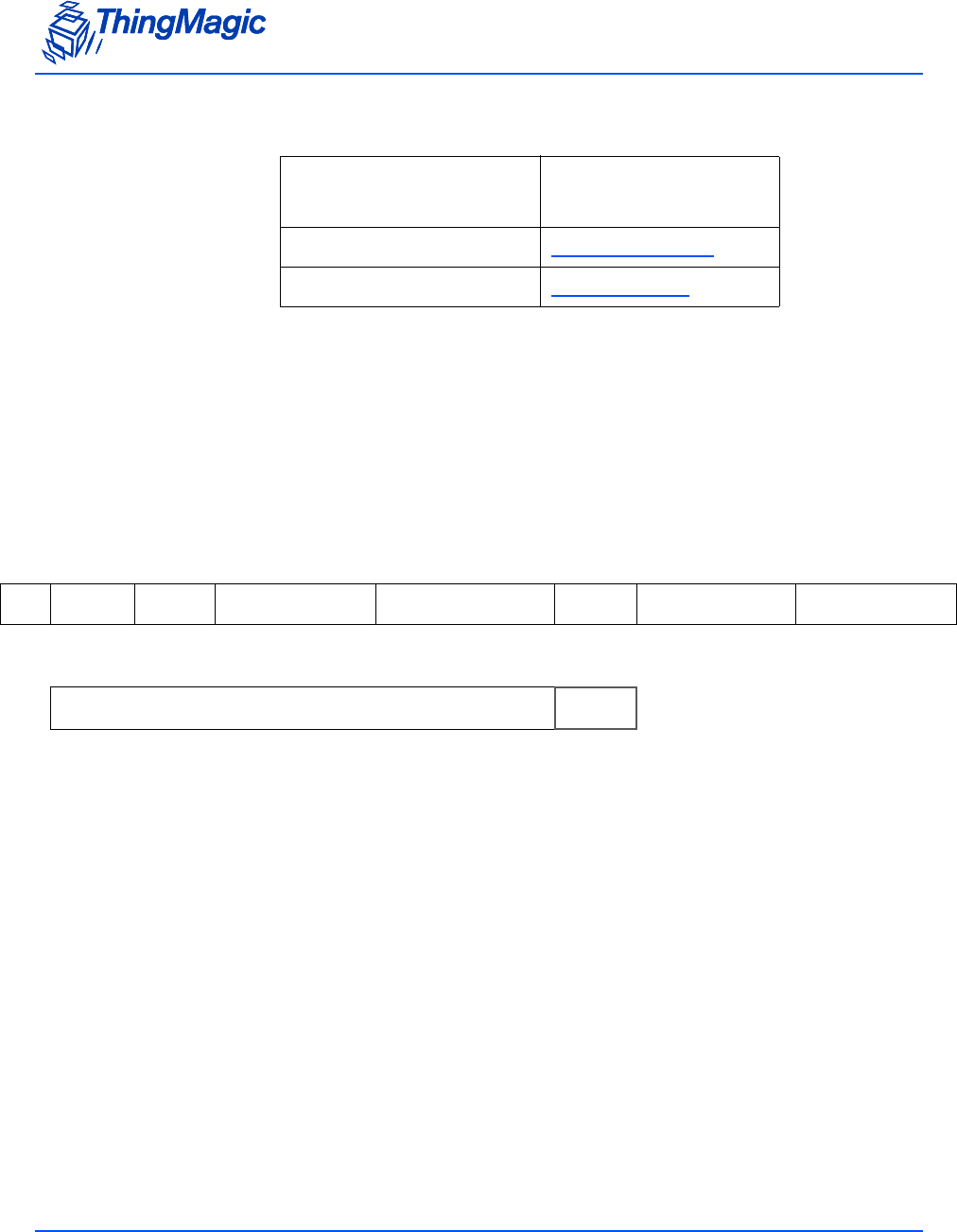
Gen2 Tag Commands
124
Alien Higgs Sub Commands
Partial Load Image
Sub Command=0x01
If the first bit of Sub Command is 1 (Sub Command=0x01), the Gen2 Tag Specific
command writes an EPC with a length of up to 96-bits, plus the Kill and Access
passwords without locking in a single command.
The format for this command is as follows:
Sub Command value Alien Higgs
Command
0x01 Partial Load Image
0x03 Full Load Image
FF 18 2D 03 E8 01 01 00 00 00 00 00 00 00 00
SO
HLength OpCode Timeout (ms) Chip Type Sub
Com-
mand
Kill Password Access Password
11 22 33 44 55 66 77 88 99 AA BB CC 45 64
Tag ID CRC

Gen2 Tag Commands
125
Full Load Image
Sub Command=0x03
If the second bit of Sub Command is 1 (Sub Command=0x03), the Gen2 Tag Specific
command will also modify the Lock bits (locking the tag according to the Alien Higgs Lock
Bits) and the Alien Higgs PC Bits.
The format is extended as follows:
The Lock Bits correspond to the Higgs TID Bank configuration bits with the same name
and are shown in the following table:
Alien Higgs Lock Bits
Currently, only the first six bits of this field are used. A value of zero in each bit field keeps
the corresponding memory segment unlocked. To lock any of the Kill and Access
passwords or the EPC, temporarily or permanently, set the corresponding bit fields in the
Lock Bits word to 1. For additional information, refer to the Higgs Tags Application Notes
FF 1C 2D 03 E8 01 03 01 23 45 67 89 A
BC
DEF
SO
HLength OpCode Timeout (ms) Chip Type Sub
Command Kill Password Access Password
00 02 30 00 11 22 33 44 55 66 77 88 99 AA B
BC
C?
??
?
Lock Bits PC Word Tag ID CRC
Bit Number 15 14 13 12 11 10 9 8 7 6
Field Name> XXXXXX X X X X
Default Values XXXXXX X X X X
Lock Values XXXXXX X X X X
5 43210
APW
Lock
APW
P-lock
KPW
Lock
KPW
P-lock
EPC
Lock
EPC
P-
lock
0 00000
1 11111

Gen2 Tag Commands
126
(Currently available at http://www.alientechnology.com/docs/
Load_Image_Application_Note_1.pdf - Contact Alien Technology for more details).
The PC Word field, in the table on the previous page, corresponds to the PC Word in the
Tag EPC memBank defined in the Gen2 Specification and is shown in the following table:
Alien Higgs PC Bits
The PC Word in the Write Tag Specific command allows you to specify the NSI Bits and
the length of the EPC that you want to write into the tag. The RFU bits are always zero
and the PC Bits are determined by the EPC length as specified in the Gen2 Specification
and the Higgs Tags Application Notes.
To use the extended format of the Gen2 Tag Specific command but keep the NSI bits
intact, set option=0x03. This signals the reader to ignore the NSI bits of the PC Word sent
to the reader along with the command.
In the example on the previous page, after the execution of the Gen2 Tag Specific
command, the reader writes the 96-bit EPC 0x112233445566778899AABBCC, the Kill
Password 0x01234567, the Access Password 0x89ABCDEF into the tag without
changing the NSI bits of the tag and locks the EPC memBank.
However, to access and write the NSI bits into the tag, set the third bit of the option field to
1 (option=0x07). In the example, if option is set to 0x07, the NSI bits are overwritten by
zeros.
The following table summarizes the option field values and the action that is taken:
Bit Number 15 14 13 12 11 10 9 8 7 6
Field Name PC Bits RFU RFU
Default Values XXXXX0 0 000
54 3 210
NSI Bits
00 0 000

Gen2 Tag Commands
127
NXP Silicon (Chip Type=0x02)
Tags with NXP Silicon support the following proprietary commands as specified in the
SL31CS1202 G2XM UCode Functional Specification (please contact NXP for details):
NXP Sub Commands
All NXP-proprietary commands contain the following fields:
Bit Number
210 Action
0 0 0 Invalid Value
001Gen2 Tag Specific without locking and without NSI bits
being overwritten
0 1 0 Invalid Value
011Gen2 Tag Specific with locking and without NSI bits being
overwritten
1 0 0 Invalid Value
101Gen2 Tag Specific without locking and with NSI bits being
overwritten by zeros
1 1 0 Invalid Value
111Gen2 Tag Specific with locking and with NSI bits being
overwritten by values that you specify
Sub Command value NXP Command
0x01 Set ReadProtect
0x02 Reset ReadProtect
0x03 Change EAS
0x04 EAS Alarm
0x05 Calibrate

Gen2 Tag Commands
128
NXP Common Fields
In addition to the common fields some commands have additional required fields as
indicated below.
Set ReadProtect
The NXP command Set ReadProtect causes the commands Read, Write, Kill, Lock,
Access, Set ReadProtect, Change EAS, EAS Alarm and Calibrate to be disabled until a
“Reset ReadProtect” is received. This command uses only the common fields and is
invoked with the following command:
The response to the Set ReadProtect command is a simple ACK with standard status:
Field Value
Length 1 byte
OpCode 0x2D
Timeout 2 bytes
Option 0x02 for NXP
Sub Command NXP Sub Commands
Access Password 4 bytes, tag’s access password
Note: Must be non-zero for Set/
Reset ReadProtect and
Change EAS
Note: EAS Alarm does not take the
Access Password field.
FF 08 2D 03 E8 02 01 12 34 56 78 ?
??
?
SO
HLength OpCode Timeout (ms) Chip
Type Sub
Com-
mand
Access Password CRC
FF 00 2D 00 00 1D 25
SOH Length OpCode Status CRC

Gen2 Tag Commands
129
Reset ReadProtect
The NXP command Reset ReadProtect restores normal operation to a tag which is in
ReadProtect mode. This command uses only the common fields and is invoked with the
following command:
The response to the Reset ReadProtect command is a simple ACK with standard status:
Change EAS
The NXP command Change EAS sets or resets the EAS system bit. When set, the tag
will return an alarm code if an “EAS Alarm” command is received. This command takes
an additional field:
Change EAS (1 byte: 0x01=Set EAS; 0x02=Reset EAS)
It is invoked with the following command:
The response to the Change EAS command is a simple ACK with standard status:
EAS Alarm
The NXP command EAS Alarm causes the tag to return coded information, but only when
the tag has its EAS system bit set. This command requires several fields in addition to the
common fields
FF 08 2D 03 E8 02 02 12 34 56 78 ?
??
?
SO
HLength OpCode Timeout (ms) Chip
Type Sub
Com-
mand
Access Password CRC
FF 00 2D 00 00 1D 25
SOH Length OpCode Status CRC
FF 09 2D 03 E8 02 03 00 00 00 00 00 ?
??
?
SO
HLength OpCode Timeout (ms) Chip
Type Sub
Com-
mand
Access Password Change
EAS CRC
FF 00 2D 00 00 1D 25
SOH Length OpCode Status CRC

Gen2 Tag Commands
130
Divide Ratio as Per Gen2 (DR) (1 byte: Current fixed to 0x01, M5e and M5e-C only
support DR=64/3)
Miller Cycles (M) (1 byte: Current fixed to 0x02, M5e and M5e-C only support M=4)
TrExt as Per Gen2 (1 byte: Current fixed to 0x01, M5e and M5e-C only support
extended Pilot Tone)
It is invoked with the following command:
The response to the EAS Alarm command contains 8 bytes of EAS Alarm Data, only if
Status=0x0000. The format of the response is:
Calibrate
The NXP command Calibrate causes the tag to return a random data pattern that is
useful in some frequency spectrum measurements. This command uses only the
common fields and is invoked with the following command:
The response to the Calibrate command contains 32 bytes of Calibrate Data, only if
Status=0x0000. The format of the response is:
FF 07 2D 03 E8 02 04 01 02 01 ?
??
?
SO
HLength OpCode Timeout (ms) Chip
Type Sub
Com-
mand
DR M TrEx
tCRC
FF 0A 2D 00 00 02 04 [8 bytes] ?? ??
SOH Length OpCode Status Chip
Type Sub
Com-
mand
[EAS Alarm
Data] CRC
FF 08 2D 03 E8 02 05 11 11 22 22 ?
??
?
SO
HLength OpCode Timeout (ms) Chip
Type Sub
Com-
mand
Access Password CRC
FF 42 2D 00 00 02 05 [64 bytes] ?? ??
SOH Length OpCode Status Chip
Type Sub
Com-
mand
[Calibrate
Data] CRC

Gen2 Tag Commands
131
Note
If the tag is a G2XL without User Memory the Calibrate Data response field
will contain 64 bytes of ‘00’.

Gen2 Tag Commands
132
Erase Block Tag Specific (2Eh)
The Erase Block Tag Specific command is used for Tag specific block erases. The
format for this command is as follows:
Currently, the only acceptable Chip Type is 0x00 (indicates standard support of any tag
supporting the Block Erase command as specified in the Gen2 Specification) and the only
permissible option is 00 (Block Erase). The 32-bit Address field is the zero-based offset
from the MemBank origin, in 16-bit words, where the contents of the tag memory will be
erased. It corresponds to the WordPtr argument in the Gen2 command specification.
The 8-bit MemBank field specifies which of the tag’s memory banks is to be addressed. It
corresponds to the Gen2 argument of the same name. Its values are as mentioned for
Write Tag Data command. Word Count specifies the number of 16-bit words to be
erased. In the format example, data starting at word=0x02 (the third word) of EPC
memory, which corresponds with the first word of the EPC ID, is erased .
FF 0A 2E 03 E8 00 00 00 00 00 02 01 01 7
B38
SOH Length OpCode Timeout (ms) Chip
Type Option Address Mem Bank Word
Count CRC

Get Configuration Commands
133
Get Configuration Commands
The Get commands listed in the following table are used to get settable parameters from
the Mercury Embedded module. All of the commands have a data length of zero, and
return data or a fault code. These commands cannot be run in the Bootloader.
Get Configuration Commands
OpCode Command Name Arguments Return
0x10 Get Hardware Version (10h) Option, Mask Hardware Information
0x61 Get Antenna Configuration (61h) Option Antenna configuration
0x62 Get Read TX Power (62h) Return Option (1
byte) Read TX Power Setting
(and optionally Min. and
Max power)
0x63 Get Current Tag Protocol (63h) none Current Tag Protocol
0x64 Get Write TX Power (64h) none Write TX Power Setting
0x65 Get Frequency Hop Table (65h) none Current Frequency Hop
Table
0x66 Get User GPIO Inputs (66h) none GPIO Input Data
0x67 Get Current Region (67h) none Current region being used
0x68 Get Power Mode (68h) none Current power mode setting
0x69 Get User Mode (69h) none Current user mode setting
0x6A Get Reader Configuration(6Ah) none Current reader configuration
options set
0x6B Get Protocol Configuration (6Bh) Protocol, Parame-
ter (2 bytes) Parameter Value
0x6C Get Reader Statistics (6Ch) Option, Statistics Reader Statistics
0x70 Get Available Protocols (70h) none Available Protocols
0x71 Get Available Regions (71h) none Available regions.
0x72 Get Current Temperature (72h) none Current module tempera-
ture

Get Configuration Commands
134
Get Hardware Version (10h)
The Get Hardware Version command is used to get information about the module it is
executed on. Most of the information is not currently user-relavant but will often be
required by ThingMagic Support to help diagnose problems.
Get Hardware Version Fields
The format of this command is:
Example
The following command returns the FPGA TM and TC versions:
The follow is an example response containing the FPGA TM and TC versions:
Field Value Description
Option 0x00 Indicates the Data Flags will following specifying the information
to be returned
0x01 M6e-TC Only - Indicates the FPGA TM and TC versions should
be returned.
Note: Do Not pass Data Flags when using Option=0x01.
Data Flags 0x00 When no flags are set all data will be returned.
FF 02 10 00 00 F0 93
SOH Length OpCode Option Data
Flags CRC
FF 01 10 01 ?? ??
SOH Length OpCode Option CRC
FF 08 10 00 00 12 34 56 78 00 10 01 04 B9 5E
SOH Length OpCode Status FPGA TM Version FPGA TC Version CRC

Get Configuration Commands
135
Get Antenna Configuration (61h)
The Get Antenna Configuration command returns the current antenna configuration
including which antennas are set to transmit and receive, and which ports have antennas
attached.
Reliable antenna detection requires that an attached antenna pass at least a small
amount of DC current. Many antennas do not pass DC current. Due to such antennas an
indication that a port is terminated is always accurate, but an indication that a port is not
terminated may not be accurate.
The format of the command is:
The reply is formatted similar to the Set Antenna Port command. Data byte 01 returns
the current TX antenna, and data byte 02 returns the current RX antenna. The default,
and currently only, antenna configuration is TX on port #1 and RX on port #1.
The Get Antenna Configuration command also includes an option that also returns
information on which port(s) the antenna is connected.
For example, a command is sent:
The response returns the ports for TX and RX and also detects whether an antenna is
connected to the port:
FF 00 61 00 1D 6E
SOH Length OpCode Option CRC
FF 02 61 00 00 01 01 4E 21
SOH Length OpCode Status TX Ant Num RX Ant Num CRC
FF 01 61 01 1D 6E
SOH Length OpCode Option CRC

Get Configuration Commands
136
Get Read TX Power (62h)
The Get Read TX Power command returns the current TX power and, optionally, the
minimum and maximum power levels supported by the module (and region setting) for
reading tags, in centi-dBm.
The option field allows you to specify what data you want returned:
The following example gets the full set of power data:
The example response contains the option specified followed by 2 byte fields for each
power value:
current = 0x0BB8 = 3000 centi-dBm = 30.00 dBm
max = 0x0BB8 = 3000 centi-dBm = 30. 00 dBm
min. = 0x01F4 = 500 centi-dBm = 5.00 dBm
Get Current Tag Protocol (63h)
The Get Current Tag Protocol command returns the currently set tag protocol(s). This is
the protocol being used by the reader. The following table assigns a 16-bit code to each
available protocol. This table will be updated as new protocols are added:
FF 05 61 00 00 01 01 00 ?/ ??
SOH Length OpCode Status TX Ant Num RX Ant Num Port 1
Not Connected CRC
Option Data returned
0x00 Returns only the current TX power.
0x01 Returns the current TX power and the maximum
and minimum power levels for this module.
FF 01 62 01 BE BC
SOH Length OpCode Option CRC
FF 07 62 00 00 01 0B B8 0B B8 01 F4 1F B7
SOH Length OpCode Status Option Current centi-dBm Max centi-dBm Min centi-dBm CRC

Get Configuration Commands
137
Tag Protocol IDs
The command format is shown in the following example:
Note
The supported protocols vary depending on the hardware and firmware in
use.
The reply is similar to the Set Current Tag Protocol command. Only one protocol can be
set at a time:
Protocol Name 16-bit Code
None Selected 0x0000
EPC0 / EPC0+ Matrics 0x0001
EPC1 0x0002
ISO 18000-6B 0x0003
EPC0+ Impinj 0x0004
GEN2 0x0005
UCODE 0x0006
iPico 0x0007
eGo 0x001B
SeGo 0x001C
ATA 0x001D
Allegro/Title-21 0x001E
FF 00 63 1D 6C
SOH Length OpCode CRC
FF 02 63 00 00 00 1B ?? ??
SOH Length OpCode Status Current Protocol CRC

Get Configuration Commands
138
Get Write TX Power (64h)
The Get Write TX Power command returns the current TX power and, optionally, the
minimum and maximum power levels supported by the module for reading tags, in centi-
dBm.
The option field allows you to specify what data you want returned:
The following example gets the full set of power data:
The example response contains the option specified followed by 2 byte fields for each
power value:
current = 0x0BB8 = 3000 centi-dBm = 30.00 dBm
max = 0x0BB8 = 3000 centi-dBm = 30.00 dBm
min. = 0x01F4 = 500centi-dBm = 5.00 dBm
Get Frequency Hop Table (65h)
The Get Frequency Hop Table command gets the current frequency hop table used in
the Microprocessor:
Option Data returned
0x00 Returns only the current TX power.
0x01 Returns the current TX power and the maximum
and minimum power levels for this module.
FF 01 64 01 B8 BC
SOH Length OpCode Option CRC
FF 07 64 00 00 01 0B B8 0B B8 01 F4 FF BC
SOH Length OpCode Status Option Default centi-dBm Max centi-dBm Min centi-dBm CRC

Get Configuration Commands
139
The reply format is similar to the Set Frequency Hop Table command. The length must
be set to a multiple of four, and a maximum of 62 hop frequencies is returned. The
frequencies are returned in kHz. Thus, frequency #1 (0xDC370) corresponds to 902,000
kHz:
Get User GPIO Inputs (66h)
The Get User GPIO Inputs command returns the status of the User Input GPIO lines:
The status of the GPIO lines is returned.
Get Current Region (67h)
The Get Current Region command gets the current region and, optionally, specific
parameters for that region set in the reader. Currently available region codes are shown
in the following table. Details on the Regulatory Compliance for each region can be found
in Regional Support::
FF 00 65 1D 6A
SOH Length OpCode CRC
FF 0C 65 00 00 00 0D C3 70 00 0D F6 38 00 0E 26 12 60 B2
SOH Length OpCode Status Freq #1 Freq #2 Freq #3 CRC
FF 00 66 1D 69
SOH Length OpCode CRC
FF 02 66 00 00 00 01 CA B2
SOH Length OpCode Status Input #1 Input #2 CRC

Get Configuration Commands
140
Region codes
To get the current region send the following command:
The command generates the following reply, which indicates that the reader is set to the
NA region:
Get Power Mode (68h)
The Get Power Mode command returns the current Power Mode of the unit. The values
for the available Power Modes are shown in the table.
Available power modes
Region Code
NA 0x01
Open 0xFF
FF 00 67 1D 68
SOH Length OpCode CRC
FF 01 67 00 00 01 B4 80
SOH Length OpCode Status Region CRC
Hex Power Mode
0x00 Full power mode
0x01 Minimal saving mode .
0x02 Medium saving mode.
0x03 Maximum saving mode.
0x04-0xFF Reserved for future use.

Get Configuration Commands
141
Note
If Set Power Mode (98h) is called using the USB interface and mode 0x03 is
specified the module will instead be set to 0x02. In order to set the module to
mode 0x03 the command must be called using the RS232 interface.
The command gets the current power mode setting from the module:
The example reply shows that the system is in the medium power saving mode:
Get User Mode (69h)
The Get User Mode command returns the type of application in which the M5e/M5e-
Compact can be used. The available user modes are shown in the table:
Available User Modes
The command gets the current user mode setting from the module:
FF 00 68 1D 67
SOH Length OpCode CRC
FF 01 68 00 00 02 A4 BD
SOH Length OpCode Status Power Mode CRC
Hex User Mode
0x00 NONE (Default)
0x01 PRINTER
0x02 Unsupported
0x03 PORTAL
0x04 HAND HELD

Get Configuration Commands
142
The example reply shows the current user mode setting:
Get Reader Configuration(6Ah)
The Get Reader Configuration command returns the current reader configuration for
the setting specified by the key field as defined in Set Reader Configuration(9Ah) when
using Option=0x01. When using Option=0x00 it will use the previous format of the
command.
Send the following command to get the current PA Protection setting:
The example reply shows the current configuration setting:
Get Protocol Configuration (6Bh)
The Get Protocol Configuration command is used to get current protocol-specific
configuration parameters settings as specified in Set Protocol Configuration (9Bh).
Send the following command to get the current Gen2 Session configuration parameter
value:
FF 00 69 1D 66
SOH Length OpCode CRC
FF 01 69 00 00 01 97 8F
SOH Length OpCode Status User Mode CRC
FF 02 6A 01 07 2E 49
SOH Length OpCode Option Key CRC
FF 03 6A 00 00 01 07 01 39 45
SOH Length OpCode Status Option Key Value CRC

Get Configuration Commands
143
The example reply shows the Gen2 session is set to S2 (0x02):
a
Get Reader Statistics (6Ch)
The Get Reader Statistics command allows the user to get and reset various statistics on
the reader operation. The command takes the following fields:
Get Reader Statistics Request Fields
FF 02 6B 05 00 3A 6F
SOH Length OpCode Protocol Parameter CRC
FF 03 6B 00 00 05 00 02 08 76
SOH Length OpCode Status Protocol Parameter Value CRC
Field Value
Option (1 byte) • 0x00 - Get statistics specified by
the Statistics Flag
• 0x01 - Reset the specified
statistic.
Statistics Flag (1 byte) Each bit corresponds to a specific
statistic to be returned. See the Avail-
able Statistics table for bit values.

Get Configuration Commands
144
Available Statistics
The response to a Get Reader Statistics command contains the following information:
Statistics Flag Bit Statistic
Bit 0 (0x01) RF On Time (ms)- Indicates the aggregate time the transmitter
has been on, in milliseconds, since the counter was last reset.
Returned value contains 8 bytes (4 on the M5e-Compact), 4
bytes for each antenna.
Note: Clock rolls over every 232 milliseconds and must
be taken into account by user application.
Note: Multiple statistics can be requested by a single command by performing a
binary OR (setting each desired Statistics Flag bit to 1) on the desired
flags and sending the result as the Statistics Flag byte.

Get Configuration Commands
145
Get Statistics Response Fields
To request the RF On Time send the following command:
The response, containing the RF On Time would look like:
To reset the RF On Time statistic send the following command:
Field Description
Status (2 bytes) Standard response status
Option (1 byte) Same as the Requested Value
Requested Statistics Flag (1
byte) Same as the Requested Value
For each individual statistics requested as part of the Requested Statistics Flag the
following fields will be repeated according to the Statistics Response value. They
will be in bit value order.
Statistic Flag (1 byte) The bit corresponding to the requested statistic.
Data Length (1 byte) Indicates how many bytes are in this statistics
response value.
Statistics Response Value (N
bytes as indicated by Data
Length)
The response value of the statistic as specified in
Available Statistics
FF 02 6C 00 01 4F 89
SOH Length OpCode Option Statistics Flag CRC
FF 08 6C 00 00 00 01 01 04 00 00 08 4C D7 D9
SOH Length OpCode Status Option Requested
Stats Flag Stat Flag
(RF On) Data
Length Antenna1 RF On Time CRC
FF 02 6C 01 01 4E 89
SOH Length OpCode Option Statistics Flag CRC

Get Configuration Commands
146
Get Available Protocols (70h)
The Get Available Protocols command returns the list of protocols that the reader is
capable of reading. The protocol codes are defined in Get Current Tag Protocol (63h). The
total number of protocols in the system cannot exceed 32. The command is generated as
follows:
The following Microprocessor response shows that the reader is capable of reading one
protocol – GEN2:
Get Available Regions (71h)
The Get Available Regions command returns the list of regions that the reader is
capable of working in. The total number of regions in the system cannot exceed 248. The
list of region codes are found in Region codes. The command is generated as follows:
The response shows that this reader is capable of reading in two regions – NA and Open:
FF 00 70 1D 7F
SOH Length OpCode CRC
FF 02 70 00 00 00 05 3B 75
SOH Length OpCode Status Protocol #1 CRC
FF 00 71 1D 7E
SOH Length OpCode CRC
FF 02 71 00 00 01 FF ?? ??
SOH Length OpCode Status Region#1 Region#2 CRC

Get Configuration Commands
147
Get Current Temperature (72h)
The Get Current Temperature command returns the current board component
temperature on the module in degrees Celsius as a signed 8-bit integer. This information
can be used to determine if the module is exceeding its recommended operating
temperature range. If the returned value exceeds the values specified in the table below
an effort should be made to reduce the ambient temperature of the module or reduce the
module’s duty cycle.
The command is generated as follows:
The response returns a signed 8-bit integer in degrees Celsius, 0x24 = 36oC
Module Warning Temperature
M6e-TC 105°C
FF 00 72 1D 7D
SOH Length OpCode CRC
FF 01 72 00 00 24 48 23
SOH Length OpCode Status Temperature in Celsius CRC

Set Configuration Commands
148
Set Configuration Commands
The Set commands are used to set configurable values in the firmware. Since the values
are not stored in flash, these values are reset to the default values whenever the
application firmware is restarted. These commands cannot be run in the Bootloader. The
application responds with a fault code / ACK to all commands.
The following table lists the Set commands:
Set Configuration Commands
OpCode Command Name Arguments Retur
n
0x91 Set Antenna Port (91h) Antenna Port Selected none
0x92 Set Read TX Power (92h) Read TX Power Setting none
0x93 Set Current Tag Protocol (93h) Protocol ID none
0x94 Set Write TX Power (94h) Power in centi-dBm none
0x95 Set Frequency Hop Table (95h) Table of hop frequencies in kHz none
0x96 Set User GPIO Outputs (96h) GPIO output states none
0x97 Set Current Region (97h) Region Codes, LBT none
0x98 Set Power Mode (98h) PowerMode Enums, Timeout (ms) none
0x99 Set User Mode (99h) UserMode Enums, Timeout (ms) none
0x9A Set Reader Configuration(9Ah) Reader Configuration Options (bitwise) none
0x9B Set Protocol Configuration (9Bh) Protocol, Parameter, Value (3 bytes) none

Set Configuration Commands
149
Set Antenna Port (91h)
The Set Antenna Port command sets the antenna port to the number specified. The
transmitter and receiver ports are specified, currently on port 0x01 is supported on the
M6e-TC. Each antenna port is an 8-bit value set up as a bit mask. Thus, only one of the
eight bits should be set at a time. The example below sets both antennas to bit mask
0x01, which would correspond to the first antenna in the system.
Valid settings for this command are:
TX = 1 RX = 1
All other settings will result in an error.
Set Read TX Power (92h)
The Set Read TX Power command sets the power level to be used for reading tags. The
power is specified as a 16-bit value in centi-dBm. For instance, a power of 25 dBm is
2500 centi-dBm, which is 0x09C4.
FF 02 91 01 01 70 3B
SOH Length OpCode TX Ant Num Rx Ant Num CRC
FF 02 92 09 C4 48 9D
SOH Length OpCode Power in centi-dBm CRC

Set Configuration Commands
150
Set Current Tag Protocol (93h)
To select a protocol, send the Set Current Tag Protocol code to the reader. A table of
valid protocol codes is found in Get Current Tag Protocol (63h). The following example sets
the protocol to GEN2:
Only protocols that are enabled in the reader are available. These protocols are listed in
the version information for the application, described in Get Boot Loader/Firmware Version
(03h).
Set Write TX Power (94h)
The Set Write TX Power command sets the power level to use for writing to tags. This is
necessary because a write operation may require a different RF power setting than a
read command. The format and arguments of this command are identical to the Set
Read TX Power command:
Set Frequency Hop Table (95h)
The Set Frequency Hop Table command sets the list of frequencies to use when
hopping. Each frequency is encoded as a 32-bit value in kHz. For instance, 915MHz is
encoded as 915000kHz, which is 0x000DF638. The maximum number of hop
frequencies is 62, since that is the maximum number of 32-bit values that can be sent
using a message packet. If fewer values are used, only those values are populated in the
table and the rest of the slots are ignored.
FF 02 93 00 05 51 7D
SOH Length OpCode Current Protocol CRC
FF 02 94 09 C4 28 5B
SOH Length OpCode Power in centi-dBm CRC
Set Configuration Commands
151
Note
The data length of this message encodes the number of frequencies to
populate into the hop table. The length must be divisible by four for the
message to be properly formatted.
This example shows a command that sets up a table with only three values:
The generated hop table has values of 902MHz, 915MHz, and 927.25MHz. For the US
region, valid frequencies are 902MHz – 928MHz. If any of the values in the table are
invalid, then none of the values are recorded.
The Set Frequency Hop Table command should be used for debug only, as there
should be no reason to modify the frequency hop table in the field.
Set User GPIO Outputs (96h)
There are two GPIO outputs available for use. The Set User GPIO Outputs command
has been “overloaded” to create a mechanism to return the current state of both GPIO
pins. To set either GPIO Output pin, send the following command. Note that the data
length is 2 bytes:
FF 0C 95 00 0D C3 70 00 0D F6 38 00 0E 26 12 C1 8F
SOH Length OpCode Freq #1 Freq #2 Freq #3 CRC
CAUTION!
!!
Any changes to the frequency hop table
could put you out of compliance with the
Local Regulatory Requirements (for exam-
ple, FCC, ETSI, MIC).
FF 02 96 01 01 28 E0
SOH Length OpCode GPIO # Output Value CRC

Set Configuration Commands
152
This example sets the GPIO Output #1 to ‘1’ (high). To get the current status of the GPIO
output pins, send the same command, with the length set to 0:
The response looks similar to the Get User GPIO Inputs command:
Set Current Region (97h)
The Set Current Region command sets the current region for use in the reader. The list
of region codes are found in Region codes. See Regional Support for more information on
regional functionality.
Setting the region performs the following:
1. Frequency hop table is set to the default for the region.
2. Any other region specific settings are set (i.e. LBT) to default values unless otherwise
specified. Currently only LBT is configurable for regions supporting it.
The Set Current Region command supports two command syntaxes:
The basic syntax for all regions where only the region code is specified. For example,
to set the region to KR:
The extended syntax allowing the region code plus LBT Enabled (if supported by
Region) to be set. For example, to set the Region to EU3 and Enable LBT:
FF 00 96 1D 99
SOH Length OpCode CRC
FF 02 96 00 00 00 01 29 E0
SOH Length OpCode Status Output #1 Output #2 CRC
FF 01 97 03 4B BE
SOH Length OpCode Region CRC
FF 02 97 08 01 19 FD
SOH Length OpCode Region LBT Enable CRC

Set Configuration Commands
153
Note
When LBT is disabled in the Open region the M6e-TC will implement
frequency hopping as implemented for the NA region with a frequency hop
interval of 400ms.
Set Power Mode (98h)
The Set Power Mode command can set the M6e-TC to four different power
management modes. See Available power modes.
Use the Set Power Mode command to set the power mode to maximum saving mode by
sending the following:
Set User Mode (99h)
Use the Set User Mode command to set the user mode to the type of application in
which the M6e-TC will be configured for the optimal Search Strategy settings for a
particular protocol.
Send the following to set the user mode to printer:
The list of user modes and their corresponding session are found in Available User Modes.
Setting the User Mode to an unsupported value will not modify the current setting.
Set Reader Configuration(9Ah)
The Set Reader Configuration command is used to set several configuration options on
the reader. The Option byte indicates whether to use the new key/value pair setting or the
previous, bitwise, settings. One example configuration and the corresponding Options
value is specified in the command example below. For other combinations the hex value
for Options will need to be calculated by OR’ing the bits for each setting.
FF 01 98 03 44 BE
SOH Length OpCode Power Mode CRC
FF 01 99 01 45 BC
SOH Length OpCode User Mode CRC

Set Configuration Commands
154
Available Configuration Options
Send the following to enable the 496 bit EPC mode:
Note
Multiple settings cannot be applied in a single command.
Set Protocol Configuration (9Bh)
The Set Protocol Configuration command is used to set protocol-specific configuration
parameters. The table below defines the currently available protocol-specific parameters
which can be set and the supported settings. Additional parameters will be supported in
the future.
Option Key Value Reader Configuration setting
0x00 Indicates the deprecated format of this command will be used.
0x01 Maximum EPC Length
= 0x02 0x00 Maximum EPC length of 96 bits (Default)
0x01 Maximum EPC length of 496 bits
Record the highest RSSI
seen
= 0x06
0x00 The RSSI Tag Read Meta Data value is the value for the
last read tag for each tag buffer entry when this is Dis-
abled. (Default)
0x01 When Enabled the RSSI Tag Read Meta Data value will
be the highest value recorded during the Read Tag Multi-
ple (22h) search operation.
PA Protection
= 0x07 0x00 Disable - Turns off Power Amplifier Protection.
NOT RECOMMENDED.
0x01 Enable (Default)
Tag Data as Unique Iden-
tifier of Tag Buffer entry.
= 0x08
0x00 Tag Data is a unique characteristic of a Tag Buffer Entry.
0x01 Tag Data is ignored for Tag Buffer Entry uniqueness
(Default)
FF 03 9A 01 02 01 AD 5C
SOH Length OpCode Option Key Value CRC

Set Configuration Commands
155
Protocol Configuration Settings
Note
Setting the parameters using Set Protocol Configuration will override the
implicit value set by a previous call to Set User Mode. Likewise, a
subsequent call to Set User Mode will override the parameters set by Set
Protocol Configuration. Get Protocol Configuration will always return the
current setting regardless of whether it was set by Set Protocol
Configuration or Set User Mode.
Set Gen2 Session
The following example sets the Gen2 session to S2:
a
Protocol Value Parameter Option Value
0x05 (Gen2) Gen2 Session used for
Inventory commands.
(0x00)
N/A 0x00 (S0 - Default)
0x01 (S1)
0x02 (S2)
0x03 (S3)
Gen2 Q Value (0x12)Dynamic (0x00) -
Automatically
adjust Q value.
N/A
Static (0x01) - User
specified Q Value
between 0 and 15.
1 byte (0x00-0x0F)
0x1B (eGo) n/a
0x1C (SeGo) n/a
0x1D (ATA) n/a
0x1E(Allegro/Title-21) n/a
FF 03 9B 05 00 02 DC EA
SOH Length OpCode Protocol Parameter Value CRC

Set Configuration Commands
156
Set Q Value
The Q valued can be set to a static user specified value or to dynamically change based
on ThingMagic internal algorithms. When using the dynamic Q setting the Value
parameter is dropped in the command.
The following example statically sets the Q value to 6:
The following example sets dynamic Q value adjusting:
FF 04 9B 05 12 01 06 80 A9
SOH Length OpCode Protocol Parameter Option Value CRC
FF 03 9B 05 12 00 CE E8
SOH Length OpCode Protocol Parameter Option CRC

FCC Test Commands
157
FCC Test Commands
The following OpCodes are used for test purposes including regulatory certification
testing. These commands cannot be run in the Bootloader.
Note
Set Power Mode to Full 0x00 before running FCC commands.
FCC Test Commands
OpCode Command Name Arguments Return BL App
0xC1 Set Operating Frequency
(C1h)
Frequency in
kHz none N Y
0xC3 Transmit CW Signal (C3h) CW mode, [tim-
eout] none N Y

FCC Test Commands
158
Set Operating Frequency (C1h)
The Set Operating Frequency command takes a 32-bit frequency value, expressed in
kHz. For instance, to set the frequency to 915.26MHz, send the data value 915260
(0x000D F73C) to the reader.
Transmit CW Signal (C3h)
The Transmit CW Signal command turns the Continuous Wave (CW) signal On or Off or
enables a PRBS signal. Sending 0x00 turns Off the CW signal; sending 0x01 turns On
the CW signal; Sending 0x02 turns on a PRBS signal. The CW signal is transmitted at the
last used power level.
This example shuts off CW:
Some regulatory testing requires a PRBS (Pseudo-Random Bit Sequence) signal to
simulate data transmission. To send a PRBS signal, along with sending CW=0x02, the
Length field must be changed to 0x03. This indicates PRBS will be used and an extra 2
byte Timeout field must be added. When this PRBS mode is used the CW signal is on
until the timeout expires, during that period the reader does not respond to commands.
The following example generates a PRBS CW signal for 256 ms, 100% duty
cycle:
FF 04 C1 00 0D F7 3C F3 B7
SOH Length OpCode Freq to Set CRC
FF 01 C3 00 1F BD
SOH Length OpCode CW CRC
FF 03 C3 02 01 00 01 00
SOH Length OpCode CW/PRBS Timeout CRC

FCC Test Commands
159
Get Operating Frequency (C8h)
The Get Operating Frequency command returns the currently operating frequency, as
set by Set Operating Frequency (C1h) for testing. The operating frequency is returned as a
32-bit value, expressed in kHz. For instance, for the frequency 915.26MHz, the value
0x000D F73C will be returned.
FF 00 C1 1D C7
SOH Length OpCode CRC

FCC Test Commands
160

Appendix A: Hardware Details 161
Appendix A: Hardware Details
This Appendix details the mechanicals for the M6e-TC including the pin 1 location for the
serial connector.
Mechanicals
The following figures detail the hardware layout of the M6e-TC Module.

Mechanicals
162 Appendix A: Hardware Details
M6e-TC Mechanicals
Antenna Connector
The M6e-TC has one MMCX connector for interfacing to the antenna.
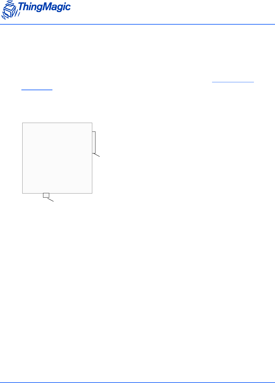
Mechanicals
Appendix A: Hardware Details 163
Communications Connector
The communications interface on the module provides power, serial communications
signals, and access to the GPIO inputs and outputs.
The M6e-TC has a 14-pin connector. For the interface pin-out, see M6e-TC Digital
Connectors.
The following figure shows a diagram of the M6e-TC communications interface as you
face the boards.
Connectors
The connectors used for the communications interface on the M6e-TC are as follows:
JST SM14B-SRSS-TB
Mating Connector:
Connector Shell: JST SHR-14V-S-B
Crimp Contacts: JST SSH-003T-PO.2-H
Pin 1
M6e-TC
Digital Connector
Antenna Port

Mechanicals
164 Appendix A: Hardware Details

Appendix B: Using the ArbSer Application 165
Appendix B: Using the ArbSer
Application
This appendix explains how to use the ArbSer application. This application provides
some simple commands for using the Mercury embedded modules to read tags.
The ArbSer program is a simple terminal program with which you can communicate with
the M4e, M5e, M5e-C, and M6e-TC modules. It provides several pre-formed commands,
as well as a raw message interface that can be used to generate any command. The
source code is part of the developer’s kit to provide an example of the message format
and CRC calculation.
The executable was built using a Windows 2000 PC. If the host PC’s operating system is
different, the executable should be rebuilt using Microsoft Visual C++ 6.0, or other
compatible compiler. If building ArbSer on another platform, some work may be
necessary to integrate the serial port properly.
ArbSer provides a help message if it is called with no argument:
C:\> ArbSer
ArbSer Version 3.2.0.
Usage: ArbSer <baud> <COM port> <option>
Default baud rate is 9600. To use 115200: ArbSer 115200 <options>
Default COM port is COM1. To use COM3: ArbSer <baud> -c3 <options>
Only one option can be used at a time:
-eraseApp – Erase application FW only (sectors 1-8).
-genMsg – Generates a msg and prints it to console.
-go – Start the application FW.
-l5a MercuryE – Load the application FW into FLASH
-l5f x.dat <addr> – Load Program file x.dat at FLASH address <addr>

166 Appendix B: Using the ArbSer Application
-msg xx xx xx ... – Send properly formatted msg (appends SOH and CRC).
-raw xx xx xx ... – Send raw hexadecimal msg (illegal msgs possible).
-ver – Returns the version information.
When using ArbSer, the serial port and baud rate can be changed from the default of
COM1 and 9600 bps. Then, one of the options must be selected. The most useful ones
are ‘-go’, ‘-msg’, and ‘-ver’. These commands provide the ability to exercise every feature
of the modules.
Reading a Tag
Now that the module is connected to the PC and is powered on, the ArbSer.exe program
is used to communicate with it. Send the sequence of commands described in this
section.
The raw hexadecimal output sent through the serial port is shown following the ArbSer
command. This is an example of the exact serial traffic sent to the Microprocessor.

Appendix B: Using the ArbSer Application 167
Get Version Command
When the unit is first powered up, the boot loader is running. Verify that the module is
alive by sending a Get Version command:
C:\> ArbSer –ver
< Equivalent to: FF 00 03 1D 0c >
Valid message received:
Data Length = 14
OpCode = 03
Status = 00 00
Data[000] = 03
Data[001] = 01
Data[002] = 00
Data[003] = 05
Data[004] = FF
Data[005] = FF
Data[006] = FF
Data[007] = FF
Data[008] = 20
Data[009] = 04
Data[010] = 11
Data[011] = 03
Data[012] = 03
Data[013] = 01
Data[014] = 00
Data[015] = 06
Data[016] = 00

168 Appendix B: Using the ArbSer Application
Data[017] = 00
Data[018] = 00
Data[019] = 07
CRC = 42EA
The module returns its version information. In the previous example, the version number
shows the following:
Boot loader version #3.1.5
Application FW build date: 11/03/2004
Application FW version #3.1.6
3 protocols enabled (EPC0, EPC1, ISO18000-6B).
Boot Firmware Command
Next, send a Boot Firmware command:
C:\> ArbSer –go
< Equivalent to: FF 00 04 1D 0B >

Appendix B: Using the ArbSer Application 169
Valid message received:
Data Length = 14
OpCode = 04
Status = 00 00
Data[000] = 03
Data[001] = 01
Data[002] = 00
Data[003] = 05
Data[004] = FF
Data[005] = FF
Data[006] = FF
Data[007] = FF
Data[008] = 20
Data[009] = 04
Data[010] = 11
Data[011] = 03
Data[012] = 03
Data[013] = 01
Data[014] = 00
Data[015] = 06
Data[016] = 00
Data[017] = 00
Data[018] = 00
Data[019] = 07
CRC = 4B6A

170 Appendix B: Using the ArbSer Application
This returns the same version information as the -ver command previously documented.
Now that the application FW has been started, the reader is ready to accept protocol
commands. To read an EPC0 tag, place the tag about one foot away from the antenna.
Then send the following series of commands.
Set Current Region Command
Before you can start reading tags with the M5e, M5e-C and M6e-TC, you must set the
region in which the reader resides.
For example, if the region is the European Union, using the Set Current Region
command, set the region as follows:
C:\> ArbSer –msg 01 97 02
<Equivalent to: FF 01 97 02 4B BE>
Valid message received:
Data Length = 00
OpCode = 93
Status = 00 00
CRC = 371A

Appendix B: Using the ArbSer Application 171
Set Current Tag Protocol Command
When the application FW first starts, there is no default protocol loaded. Thus, the
protocol to use must be specified.
For this example, the protocol is set to EPC0 using the Set Current Tag Protocol
command:
C:\> ArbSer –msg 02 93 00 01
< Equivalent to: FF 02 93 00 01 51 79 >
Valid message received:
Data Length = 00
OpCode = 93
Status = 00 00
CRC = 371A
Set Read TX Power Command
The default read power setting for the modules is 26.5 dBm. This should be adequate to
read the tag from 1 foot. If a different power setting is desired, it should be entered now.
The following Set Read TX Power command sets the power level to 25.0 dBm (0x09C4):
C:\> ArbSer –msg 02 92 09 C4
< Equivalent to: FF 02 92 09 C4 FC E5 >
Valid message received:
Data Length = 00
OpCode = 92
Status = 00 00
CRC = 273B
Set Antenna Port Command
The default antenna port configuration is a 2-port antenna, with TX on port 1 and RX on
port 2. If a different configuration is being used, it should be changed before attempting to

172 Appendix B: Using the ArbSer Application
read tags. For example, to use a one-port configuration that uses only port 1, use the Set
Antenna Port command:
C:\> ArbSer –msg 02 91 01 01
< Equivalent to: FF 02 91 01 01 70 3B >
Valid message received:
Data Length = 00
OpCode = 91
Status = 00 00
CRC = 1758
Finally, the module is ready to execute a read command. The timeout for the read can be
set anywhere from 0 ms to 65,536 ms. Using the Read Single Tag ID command, the
timeout is set to 1 s, which is 1000 ms (0x03E8):

Appendix B: Using the ArbSer Application 173
C:\> ArbSer –msg 02 21 03 E8
< Equivalent to: FF 02 21 03 E8 D5 09 >
Valid message received:
Data Length = 0E
OpCode = 21
Status = 00 00
Data[000] = 12
Data[001] = 34
Data[002] = 56
Data[003] = 78
Data[004] = 9A
Data[005] = BC
Data[006] = DE
Data[007] = F0
Data[008] = AA
Data[009] = BB
Data[010] = CC
Data[011] = DD
Data[012] = 23
Data[013] = 79
CRC = 2384
The module should now return the tag ID of the tag. In this example, the 96-bit EPC0 tag
ID is (0x12 34 56 78 9A BC DE F0 AA BB CC DD) with a tag ID CRC of 0x2379.

174 Appendix B: Using the ArbSer Application
Unexpected Results
Sometimes you do not get the results that you expected. The following sections explain
some problems that can occur when the previously listed sequence of commands are
used. The following sections explain some of the frequently encountered errors.
Serial Communication Does Not Work
If serial communications fails to work using the ArbSer command, check the following:
The baud rate is correct.
If the baud rate of the boot loader or application FW was changed, then specify the
current baud rate using ArbSer. For example, “ArbSer <baudrate> ...”.
The correct COM port is being used.
ArbSer does not return an error if it is able to open the specified COM port. Currently,
ArbSer works on COM1 to COM9.
The commands are properly formed.
If no SOF byte (0xFF) is used, or an incorrect CRC or number of data elements is
specified, then the Microprocessor does not respond to the message at all.
The module is properly connected and powered on.
The serial cable should not be a NULL modem cable.
The PC serial port is working properly.
An RS-232 line checker is helpful for this.
A simple way to check that serial communications is working is to try sending a Get
Version command. If a valid response is received, then the physical communication layer
is intact and working properly. That is to say that the baud rate, COM port, and cables are
all fine.
Commands Return a Non-Zero Status Code
If a command returns a non-zero status code, this is not always an error. However, if a
non-zero code is received in response to a Set command, such as Set Current Tag
Protocol, Set Read TX Power, or Set Antenna Port commands, it is likely that one of
the following problems exists:
The module is still executing the boot loader program.

Appendix B: Using the ArbSer Application 175
Send a Boot Firmware command to verify that the application FW is running. If the
boot loader is currently running, then a set command will return a 0x0101 status
code, indicating an invalid OpCode.
The parameter(s) to the set command are invalid. If an invalid parameter is sent, then
a 0x0105 status code is returned, indicating an invalid parameter value.
If the wrong number of data elements is used, then a 0x0100 status code (wrong
number of data) is returned. This could be the result of an ill-formed command, or
accidentally using the wrong OpCode.
No Tag ID is Returned
If the Read Tag ID Single command returns an error code of 0x0400 (no tag found), then
most likely it is a set up related issue. Check the following items:
The antenna is properly connected to the unit and configured using the Set Antenna
Port command.
The tag is the right protocol (that is EPC0) and that the protocol has been set using
the Set Current Tag Protocol command.
Try using a longer timeout, such as 30 seconds, and varying the tag’s location in
relation to the antenna.
It is also possible the tag may be erased or damaged. Without a second “known good”
reader, it is difficult to tell if this is the case. If a “known good” tag is available, try to
read it.

176 Appendix B: Using the ArbSer Application
Appendix C: Error Messages 177
Appendix C: Error Messages
The following error codes were incorporated into the reader for help in locating errors.
Common Error Messages
The following table lists the common faults discussed in this section.
FAULT_MSG_WRONG_NUMBER_OF_DATA – (100h)
Cause
If the data length in any of the Host-to-M5e/M5e-Compact messages is less than or more
than the number of arguments in the message, the reader returns this message.
Fault Message Code
FAULT_MSG_WRONG_NUMBER_OF_DATA – (100h) 100h
FAULT_INVALID_OPCODE – (101h) 101h
FAULT_UNIMPLEMENTED_OPCODE – 102h 102h
FAULT_MSG_POWER_TOO_HIGH – 103h 103h
FAULT_MSG_INVALID_FREQ_RECEIVED (104h) 104h
FAULT_MSG_INVALID_PARAMETER_VALUE - (105h) 105h
FAULT_MSG_POWER_TOO_LOW - (106h) 106h
FAULT_UNIMPLEMENTED_FEATURE - (109h) 109h
FAULT_INVALID_BAUD_RATE - (10Ah) 10Ah

Common Error Messages
178 Appendix C: Error Messages
Solution
Make sure the number of arguments matches the data length.
FAULT_INVALID_OPCODE – (101h)
Cause
The opCode received is invalid or not supported with the current version of code.
Solution
Check the documentation for the opCode the host sent and make sure it is supported.
FAULT_UNIMPLEMENTED_OPCODE – 102h
Cause
Some of the reserved commands might return this error code.
This does not mean that they always will do this since ThingMagic reserves the right to
modify those commands at anytime.
Solution
Check the documentation for the opCode the host sent to the reader and make sure it is
supported.
FAULT_MSG_POWER_TOO_HIGH – 103h
Cause
A message was sent to set the read or write power to a level that is higher than the
current HW supports.

Common Error Messages
Appendix C: Error Messages 179
Solution
Check the HW specifications for the supported powers and insure that the level is not
exceeded.
The M5e 1 Watt units support power from 5 dBm to 30 dBm.
The M5e-Compact units support power from 10 dBm to 23 dBm.
FAULT_MSG_INVALID_FREQ_RECEIVED (104h)
Cause
A message was received by the reader to set the frequency outside the supported range
Solution
Make sure the host does not set the frequency outside this range or any other locally
supported ranges.
FAULT_MSG_INVALID_PARAMETER_VALUE - (105h)
Cause
The reader received a valid command with an unsupported or invalid value within this
command.
For example, currently the module supports two antennas, 1 and 2. If the module
receives a message with an antenna value other than 1 or 2, it returns this error.
Solution
Make sure the host sets all the values in a command according to the values published in
this document.
FAULT_MSG_POWER_TOO_LOW - (106h)
Cause
A message was received to set the read or write power to a level that is lower than the
current HW supports.

Common Error Messages
180 Appendix C: Error Messages
Solution
Check the HW specifications for the supported powers and insure that level is not
exceeded. The M5e supports powers between 5 and 30 dBm. The M5e-Compact units
support power from 10 dBm to 23 dBm.
FAULT_UNIMPLEMENTED_FEATURE - (109h)
Cause
Attempting to invoke a command not supported on this firmware or hardware.
Solution
Check the command being invoked against the documentation.
FAULT_INVALID_BAUD_RATE - (10Ah)
Cause
When a Set Baud Rate (0x06h) command is issued for a rate that is not specified in the
Baud Rate table, this error message is returned.
Solution
Check the table of specific baud rates and select a baud rate. Send the baud rate in the
hex format. See Set Baud Rate (06h).

Bootloader Faults
Appendix C: Error Messages 181
Bootloader Faults
The following table lists the common faults discussed in this section.
FAULT_BL_INVALID_IMAGE_CRC – 200h
Cause
When a Verify Image CRC (0x08), or Boot Firmware (0x02) command is issued, the
reader checks the image stored in flash and returns this error if the calculated CRC is
different than the one stored in flash.
Solution
The exact reason for the corruption could be that the image loaded in flash was corrupted
during the transfer or corrupted for some other reason.
To fix this problem, reload the application code in flash.
FAULT_BL_INVALID_APP_END_ADDR – 201h
Cause
When a Verify Image CRC (0x08), or Boot Firmware (0x02) command is issued, the
reader checks the image stored in flash and returns this error if the last word stored in
flash does not have the correct address value.
Solution
The exact reason for the corruption could be that the image loaded in flash got corrupted
during the transfer or, corrupted for some other reason.
To fix this problem, reload the application code in flash.
Fault Message Code
FAULT_BL_INVALID_IMAGE_CRC 200h
FAULT_BL_INVALID_APP_END_ADDR 201h
FPGA Faults
182 Appendix C: Error Messages
FPGA Faults
The following table lists the common faults discussed in this section.
FAULT_PROGRAM_ERASE_FAILED – 2E0h
Cause
When a boot firmware (0x02) is issued during an FPGA image load and the erase of the
FPGA FlashROM pages fails
Solution
Power cycle the module and reload the FPGA load application and FPGA image. If
problem persists try a previous version of the FPGA Loag Image application with the
same DAT file.
FAULT_PROGRAM_FAILED – 2E1h
Cause
When a boot firmware (0x02) is issued during an FPGA image load and the programming
of the FPGA FlashROM pages fails.
Solution
Power cycle the module and reload the FPGA load application and FPGA image. If
problem persists try a previous version of the FPGA Loag Image application with the
same DAT file.
Fault Message Code
FAULT_PROGRAM_ERASE_FAILED – 2E0h 2E0h
FAULT_PROGRAM_FAILED – 2E1h 2E1h
FAULT_PROGRAM_VERIFY_FAILED – 2E2h 2E2h
FAULT_PROGRAM_OPERATION_FAILED – 2E3h 2E3h
FAULT_PROGRAM_NOT_LOADED – 2E4h 2E4h

FPGA Faults
Appendix C: Error Messages 183
FAULT_PROGRAM_VERIFY_FAILED – 2E2h
Cause
When a boot firmware (0x02) is issued during an FPGA image load and the verification of
the FPGA FlashROM pages fails.
Solution
Power cycle the module and reload the FPGA load application and FPGA image. If
problem persists try a previous version of the FPGA Load Image application with the
same DAT file.
FAULT_PROGRAM_OPERATION_FAILED – 2E3h
Cause
When a boot firmware (0x02) is issued after the FPGA image is loaded and the
verification of the FPGA version and testing of the 16-bit FPGA-ATMEL parallel interface
fails.
Solution
Power cycle the module and reload the FPGA load application and FPGA image. Check
that the FPGA TM and TC version numbers start with 0x1234xxxx and 0x0010,
respectively. If problem persists contact support@thingmagic.com.
FAULT_PROGRAM_NOT_LOADED – 2E4h
Cause
When a boot firmware (0x02) is issued and the FPGA DAT file has not been loaded.
Solution
Power cycle the module and reload the FPGA load application and FPGA image. If
problem persists try a previous version of the FPGA Load Image application with the
same DAT file.

Flash Faults
184 Appendix C: Error Messages
Flash Faults
The following table lists the common faults discussed in this section.
FAULT_FLASH_BAD_ERASE_PASSWORD – 300h
Cause
A command was received to erase some part of the flash but the password supplied with
the command was incorrect.
Solution
Make sure that you have the correct password for the flash sector.
Go to the Erase Flash Sector (07h) section for more information about the flash passwords
and sectors.
FAULT_FLASH_BAD_WRITE_PASSWORD – 301h
Cause
A command was received to write some part of the flash but the password supplied with
the command was not correct.
Fault Message Code
FAULT_FLASH_BAD_ERASE_PASSWORD – 300h 300h
FAULT_FLASH_BAD_WRITE_PASSWORD – 301h 301h
FAULT_FLASH_UNDEFINED_ERROR – 302h 302h
FAULT_FLASH_ILLEGAL_SECTOR – 303h 303h
FAULT_FLASH_WRITE_TO_NON_ERASED_AREA – 304h 304h
FAULT_FLASH_WRITE_TO_ILLEGAL_SECTOR – 305h 305h
FAULT_FLASH_VERIFY_FAILED – 306h 306h

Flash Faults
Appendix C: Error Messages 185
Solution
Make sure that you have the correct password for the flash sector.
Check the Write Flash Sector (0Dh) for more information about the flash passwords and
sectors.
FAULT_FLASH_UNDEFINED_ERROR – 302h
Cause
This is an internal error and it is caused by a software problem in module.
Solution
Contact support at support@thingmagic.com.
FAULT_FLASH_ILLEGAL_SECTOR – 303h
Cause
An erase or write flash command was received with the sector value and password not
matching.
Solution
Make sure that you have the correct password for the flash sector.
Go to Accessing the Flash for more information about the flash passwords and sectors.
FAULT_FLASH_WRITE_TO_NON_ERASED_AREA – 304h
Cause
The module received a write flash command to an area of flash that was not previously
erased.
Solution
Erase that sector of flash and then, try and rewrite to it.

Flash Faults
186 Appendix C: Error Messages
FAULT_FLASH_WRITE_TO_ILLEGAL_SECTOR – 305h
Cause
The module received a write flash command to write across a sector boundary that is
prohibited.
Solution
If the data spans two sectors, separate the data into two messages.
FAULT_FLASH_VERIFY_FAILED – 306h
Cause
The module received a write flash command that was unsuccessful because data being
written to flash contained an uneven number of bytes.
Solution
Verify that the data being sent is an even number of bytes.
Protocol Faults
Appendix C: Error Messages 187
Protocol Faults
The following table lists the common faults discussed in this section.
Fault Message Code
FAULT_NO_TAGS_FOUND – (400h) 400h
FAULT_NO_PROTOCOL_DEFINED – 401h 401h
FAULT_INVALID_PROTOCOL_SPECIFIED – 402h 402h
FAULT_WRITE_PASSED_LOCK_FAILED – 403h 403h
FAULT_PROTOCOL_NO_DATA_READ – 404h 404h
FAULT_AFE_NOT_ON – 405h 405h
FAULT_PROTOCOL_WRITE_FAILED – 406h 406h
FAULT_NOT_IMPLEMENTED_FOR_THIS_PROTOCOL – 407h 407h
FAULT_PROTOCOL_INVALID_WRITE_DATA – 408h 408h
FAULT_PROTOCOL_INVALID_ADDRESS – 409h 409h
FAULT_GENERAL_TAG_ERROR – 40Ah 40Ah
FAULT_DATA_TOO_LARGE – 40Bh 40Bh
FAULT_PROTOCOL_INVALID_KILL_PASSWORD – 40Ch 40Ch
FAULT_PROTOCOL_KILL_FAILED - 40Eh 40Eh
FAULT_PROTOCOL_BIT_DECODING_FAILED - 40Fh 40Fh
FAULT_PROTOCOL_INVALID_EPC – 410h 410h
FAULT_PROTOCOL_INVALID_NUM_DATA – 411h 411h
FAULT_GEN2 PROTOCOL_OTHER_ERROR - 420h 420h
FAULT_GEN2_PROTOCOL_MEMORY_OVERRUN_BAD_PC -
423h
423h
FAULT_GEN2 PROTOCOL_MEMORY_LOCKED - 424h 424h
FAULT_GEN2 PROTOCOL_INSUFFICIENT_POWER - 42Bh 42Bh
FAULT_GEN2 PROTOCOL_NON_SPECIFIC_ERROR - 42Fh 42Fh
FAULT_GEN2 PROTOCOL_UNKNOWN_ERROR - 430h 430h

Protocol Faults
188 Appendix C: Error Messages
FAULT_NO_TAGS_FOUND – (400h)
Cause
A command was received (such as like read, write, or lock) but the operation failed. There
are many reasons that can cause this error to occur.
Here is a list of possible reasons that could be causing this error:
No tag in the RF field
Read/write power too low
Antenna not connected
Tag is weak or dead
Solution
Make sure there is a good tag in the field and all parameters are set up correctly. The best
way to check this is to try few tags of the same type to rule out a weak tag. If none
passed, then it could be SW configuration such as protocol value, antenna, and so forth,
or a placement configuration like a tag location.
FAULT_NO_PROTOCOL_DEFINED – 401h
Cause
A command was received to perform a protocol command but no protocol was initially
set. The reader powers up with no protocols set.
Solution
A Set Current Tag Protocol (63h) command must be sent followed by resending the
desired command.
FAULT_INVALID_PROTOCOL_SPECIFIED – 402h
Cause
A Set Current Tag Protocol (63h) command was received for a protocol value that is not
supported with the current version of SW.

Protocol Faults
Appendix C: Error Messages 189
Solution
This value is invalid or this version of SW does not support the protocol value. Check the
documentation for the correct values for the protocols in use.
FAULT_WRITE_PASSED_LOCK_FAILED – 403h
Cause
During a Write Tag Data for ISO18000-6B or UCODE, if the lock fails, this error is
returned. The write command passed but the lock did not. This could be a bad tag.
Solution
Try to write a few other tags and make sure that they are placed in the RF field.
FAULT_PROTOCOL_NO_DATA_READ – 404h
Cause
A Read Tag ID or Data command was sent but did not succeed.
Solution
The tag used has failed or does not have the correct CRC. Try to read a few others to
check the HW/SW configuration.
FAULT_AFE_NOT_ON – 405h
Cause
A command was received for an operation, like read or write, but the minimum required
configuration has not been set.
Solution
Check that the region has been set, then rerun the command.

Protocol Faults
190 Appendix C: Error Messages
FAULT_PROTOCOL_WRITE_FAILED – 406h
Cause
This fault can occur when an operation such as write, lock, kill, set password, or initialize,
fails. There are many reasons for failure.
Solution
Check that the tag is good and try another operation on a few more tags.
FAULT_NOT_IMPLEMENTED_FOR_THIS_PROTOCOL –
407h
Cause
A command was received which is not supported by a protocol.
Solution
Check the documentation for the supported commands and protocols.
FAULT_PROTOCOL_INVALID_WRITE_DATA – 408h
Cause
In EPC0+, the first two bits determine the tag ID length. If the first two bits are 0b00, then
the tag ID must be 96-bits. Otherwise the tag ID is 64 bits.
Solution
Make sure that the first two bit have the correct values depending in the Tag ID length.
FAULT_PROTOCOL_INVALID_ADDRESS – 409h
Cause
A command was received attempting to access an invalid address in the tag data address
space.

Protocol Faults
Appendix C: Error Messages 191
Solution
Make sure that the address specified is within the scope of the tag data address space
and available for the specific operation. The protocol specifications contain information
about the supported addresses.
FAULT_GENERAL_TAG_ERROR – 40Ah
Cause
This error is used by the M5e GEN2 module. This fault can occur if the read, write, lock,
or kill command fails. This error can be internal or functional.
Solution
Make a note of the operations you were performing and contact ThingMagic at http://
support.thingmagic.com
FAULT_DATA_TOO_LARGE – 40Bh
Cause
A command was received to Read Tag Data with a data value larger than expected or it is
not the correct size.
Solution
Check the size of the data value in the message sent to the reader.
FAULT_PROTOCOL_INVALID_KILL_PASSWORD – 40Ch
Cause
An incorrect kill password was received as part of the Kill Tag (26h) command.
Solution
Check the password.

Protocol Faults
192 Appendix C: Error Messages
FAULT_PROTOCOL_KILL_FAILED - 40Eh
Cause
Attempt to kill a tag failed for an unknown reason
Solution
Check tag is in RF field and the kill password.
FAULT_PROTOCOL_BIT_DECODING_FAILED - 40Fh
Cause
Attempting to operate on a tag with an EPC length greater than the Maximum EPC length
setting.
Solution
Call Set Reader Configuration(9Ah) to set the Max EPC to 496 bits.
FAULT_PROTOCOL_INVALID_EPC – 410h
Cause
This error is used by the GEN2 module indicating an invalid EPC value has been
specified for a Select operation. This fault can occur if the read, write, lock, or kill
command fails. This error can be internal or functional.
Solution
Check the EPC value that is being passed in the command resulting in this error.
FAULT_PROTOCOL_INVALID_NUM_DATA – 411h
Cause
This error is used by the GEN2 module indicating invalid data has been specified for an
operation. This fault can occur if the read, write, lock, or kill command fails.

Protocol Faults
Appendix C: Error Messages 193
Solution
Check the data that is being passed in the command resulting in this error.
FAULT_GEN2 PROTOCOL_OTHER_ERROR - 420h
FAULT_GEN2_PROTOCOL_MEMORY_OVERRUN_BAD_PC - 423h
FAULT_GEN2 PROTOCOL_MEMORY_LOCKED - 424h
FAULT_GEN2 PROTOCOL_INSUFFICIENT_POWER - 42Bh
FAULT_GEN2 PROTOCOL_NON_SPECIFIC_ERROR - 42Fh
FAULT_GEN2 PROTOCOL_UNKNOWN_ERROR - 430h

Analog Hardware Abstraction Layer Faults
194 Appendix C: Error Messages
Analog Hardware Abstraction Layer Faults
FAULT_AHAL_INVALID_FREQ – 500h
Cause
A command was received to set a frequency outside the specified range.
For example, in North America the frequency range is from 902 MHz to 928 MHz.
Solution
Check the values you are trying to set and be sure that they fall within this range.
FAULT_AHAL_INVALID_FREQ – 501h
Cause
With LBT enabled an attempt was made to set the frequency to an occupied channel.
Solution
Try a different channel.
FAULT_AHAL_TRANSMITTER_ON – 502h
Cause
Checking antenna status while CW is on is not allowed.
Solution
Do not perform antenna checking when CW is turned on.

Analog Hardware Abstraction Layer Faults
Appendix C: Error Messages 195
FAULT_ANTENNA_NOT_CONNECTED – 503h
Cause
An attempt was made to transmit on an antenna which did not pass the antenna detection
when antenna detection was turned on.
Solution
Connect a detectable antenna (antenna must have some DC resistance).
FAULT_TEMPERATURE_EXCEED_LIMITS – 504h
Cause
The module has exceeded the maximum or minimum operating temperature and will not
allow an RF operation until it is back in range.
Solution
Take steps to resolve thermal issues with module:
Reduce duty cycle
Add heat sink
FAULT_LOW_RETURN_LOSS – 505h
Cause
The module has detected a low return loss and has ended RF operation to avoid module
damage.
Solution
Take steps to resolve low return loss on receiver:
Make sure antenna VSWR is within module specifications
Make sure antennas are correctly attached before transmitting
Check environment to ensure no occurrances of high signal reflection back at
antennas.

Tag ID Buffer Faults
196 Appendix C: Error Messages
Tag ID Buffer Faults
The following table lists the common faults discussed in this section.
FAULT_TAG_ID_BUFFER_NOT_ENOUGH_TAGS_AVAILA
BLE – 600h
Cause
A command was received to get a certain number of tag ids from the tag id buffer. The
reader contains less tag ids stored in its tag id buffer than the number the host is sending.
Solution
Send a Get Tag ID Buffer command to ascertain how many tags are in the buffer. You
can get the exact number of tags as long as they are less than or equal to the number
returned by the previous command.
FAULT_TAG_ID_BUFFER_FULL – 601h
Cause
The tag id buffer is full.
Solution
Send Clear Tag ID Buffer or Get Tag ID Buffer command with the number of tags to
read, to get more space See Get Tag Buffer (29h) for more information.
Fault Message Code
FAULT_TAG_ID_BUFFER_NOT_ENOUGH_TAGS_AVAILABLE – 600h 600h
FAULT_TAG_ID_BUFFER_FULL – 601h 601h
FAULT_TAG_ID_BUFFER_REPEATED_TAG_ID – 602h 602h
FAULT_TAG_ID_BUFFER_NUM_TAG_TOO_LARGE – 603h 603h

Tag ID Buffer Faults
Appendix C: Error Messages 197
FAULT_TAG_ID_BUFFER_REPEATED_TAG_ID – 602h
Cause
The module has an internal error. One of the protocols is trying to add an existing TagID
to the buffer.
Solution
Report this problem to ThingMagic at http://support.thingmagic.com.
FAULT_TAG_ID_BUFFER_NUM_TAG_TOO_LARGE – 603h
Cause
The module received a request to retrieve more tags than is supported by the current
version of the software.
Solution
Locate the maximum number of supported tags in the TagID buffer in this document Get
Tag Buffer (29h).

System Errors
198 Appendix C: Error Messages
System Errors
FAULT_SYSTEM_UNKNOWN_ERROR – 7F00h
Cause
The error is internal.
Solution
Make note of the operations you were executing and contact ThingMagic at http://
support.thingmagic.com.
FAULT_TM_ASSERT_FAILED – 7F01h
Cause
An unexpected Internal Error has occurred.
Solution
This error will cause the module to switch back to Bootloader mode. When this occurs,
make note of the operations you were executing, save FULL error response, and contact
ThingMagic at support@thingmagic.com.

Appendix D: FPGA Support 199
Appendix D: FPGA Support
This appendix explains how to create and update Field Programmable Gate Array
(FPGA) images for the M6e-TC.
Creating an FPGA Image DAT File
Creating an FPGA Image DAT file requires the use of an Actel programming environment.
In the following instructions the use of Libero 8.4 is assumed. The process for other
Libero versions or Actel programming environments may vary. This process assumes
Verilog files have been pre-compiled and you are at the compiling stage.
In order to create an FPGA image DAT file from STAPL output the following programs are
required:
Libero Designer - Verilog/VHDL complier to build the STAPL (.stp) file.
datgen.exe - Windows command line tool for converting the STAPL output to a .dat
binary format.
Follow these steps to build the DAT file:
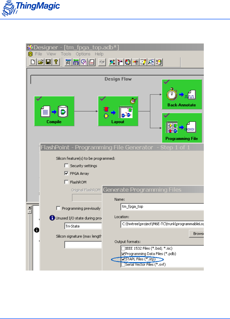
Creating an FPGA Image DAT File
200 Appendix D: FPGA Support
1. Generate the STAPL file - When generating output from Designer make sure to
select the STAPL files option for the Output files to be generated as shown below.
2. Generate the DAT file - Once the *.stp file has been generated it can be fed into the
datgen.exe utility to generate the .dat file. datgen must be run from the command
line.

Creating an FPGA Image DAT File
Appendix D: FPGA Support 201
Note: Datgen.exe only seems to run on a local drive; operating datgen.exe from a network
mapped drive may fail.
Typical output, using the STAPL file: tm_fpga_top.stp file as its input, is shown below:
C:\>datgen tm_fpga_top.stp
DirectC Version 2.x
Copyright (C) 2002 - 2007 Actel Corporation
Checking STAPL file CRC value..
Actual CRC = 7D55
Reading STAPL file...
Generating .dat files...
Image size = 129680
Data compression = 0
Stapl Target ID = 3A121CF
Tool version = 1
Map version = 1
Core Support = 1
FROM support = 0
NVM support = 0
NVM_Block0 support = 0
NVM_Block1 support = 0
NVM_Block2 support = 0
NVM_Block3 support = 0
NVM verifiy = 0
Pass key support = 0
AES key support = 0
Core security Status = 0
From Security Status = 0
NVM_BLOCK0 Security Status = 0
NVM_BLOCK1 Security Status = 0
NVM_BLOCK2 Security Status = 0
NVM_BLOCK3 Security Status = 0
Image CRC = 244B
Done.
C:\>dir *.dat
03/13/2009 02:15 PM 129,680 tm_fpga_top.dat
1 File(s) 129,680 bytes
0 Dir(s) 23,756,279,808 bytes free
3. The resulting tm_fpga_top.dat can now be loaded onto the M6e-TC using the
process described in Loading an FPGA Image.

Creating an FPGA Image DAT File
202 Appendix D: FPGA Support
WARNING!
When loading an FPGA Image onto the M6e-TC, the Verification process
checks the 16 most significant bits of the FPGA TM and TC version
numbers. To pass, the TM and TC versions must start with 0x1234xxxx
and 0x0010xxxx, respectively. When incrementing version numbers in
the Verilog/VHDL files be sure to only change the 16 least significant
bits.

Loading an FPGA Image
Appendix D: FPGA Support 203
Loading an FPGA Image
The ArbSer (see Appendix B: Using the ArbSer Application) program can also be used to
load FPGA images. In order to load an FPGA image the following files are required:
Arbser.exe - minimum version 3.2.0.
m6etc_fpga_mod.sim - FPGA load application image to be loaded into the M6e-TC
which will be used to update the FPGA image defined by the FPGA Image file.
FPGA Image file - FPGA image file in DAT format to be loaded into the M6e-TC
FPGA.
The following describes how to load an image onto the M6e-TC FPGA. These steps must
be followed carefully. If FPGA Faults occur please follow the suggested solution and retry
the image load.
1. Load the FPGA load application program into the M6e-TC using the following
command:
> arbser -l5a m6etc_fpga_mod.sim
2. Load the FPGA image file into flash within the application sector at address 0x8000.
> arbser -l5f [fpgaimage.dat] 8000
3. Initiate the image load.
> arbser -go
This executes the FPGA application program and starts the FPGA programming
process. The FPGA’s FlashROM is erased, the FPGA image is loaded and, finally,
the image is verified (see Note below). This operation takes about three minutes to
complete and should not be interrupted. On successful completion the FPGA version
information is verified and write and read verify operations are performed to check
the ATMEL <> FPGA interface. If these checks pass, the M6e-TC responds with
status and version information similar to the response for the Get Version Command
but with opcode=0x04 and the module returns to the Boot Loader mode.
4. Once the FPGA load has successfully completed the M6e-TC Application firmware
must be reloaded using the following command:
> arbser -l5a [M6e-TC App Firmware .sim]
For FPGA version information use the Get Hardware Version (10h) command..

Loading an FPGA Image
204 Appendix D: FPGA Support