Yaesu Musen 20345X40 SCANNING RECEIVER User Manual FTM 400DR Operating Manual
Yaesu Musen Co., Ltd. SCANNING RECEIVER FTM 400DR Operating Manual
Contents
- 1. User Manual
- 2. User Manual 1
- 3. User Manual 2
- 4. User Manual 3
- 5. User Manual 4
- 6. User Manual 5
- 7. User Manual 6
- 8. User Manual 7
- 9. User Manual 8
- 10. User Manual 9
- 11. User Manual 10
- 12. User Manual 11
- 13. User Manual 12
- 14. User Manual 13
- 15. User Manual 14
- 16. User Manual 15
- 17. User Manual 16
- 18. User Manual 17
- 19. User Manual 18
- 20. User Manual 19
- 21. User Manual 20
- 22. User Manual 21
User Manual

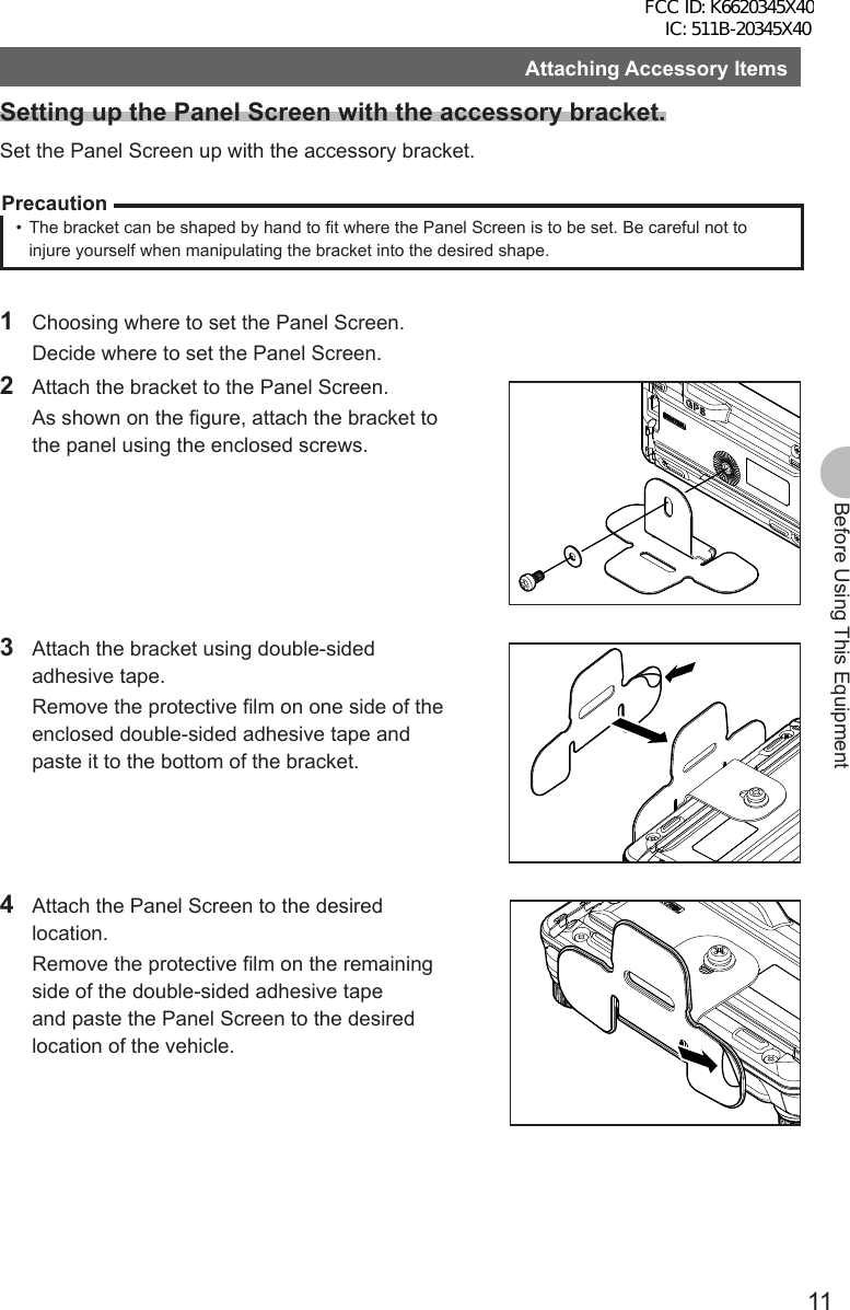
![10Before Using This EquipmentAttaching Accessory ItemsConnecting the Panel Screen to the Main UnitConnect the Panel to the Main Unit.Precaution zMake sure to turn off the Main Unit when connecting the Panel Screen to the Main Unit.1 Connect the accessory cable to the Main Unit. Connect the cable to the [CONTROL] port of the Main Unit.2 Connect the cable to the Panel Screen. Connect the cable to the [CONTROL] port of the Panel Screen.Connect the accessory microphone (MH-48).1 Insert the microphone (MH-48) into the MIC port of the Main Unit. As shown in the image on the right, connect the accessory microphone (MH-48) to the MIC port of the Main Unit. Reference • When removing the microphone, pull it out while pressing [PUSH ▼].FCC ID: K6620345X40 IC: 511B-20345X40](https://usermanual.wiki/Yaesu-Musen/20345X40.User-Manual/User-Guide-1854126-Page-11.png)
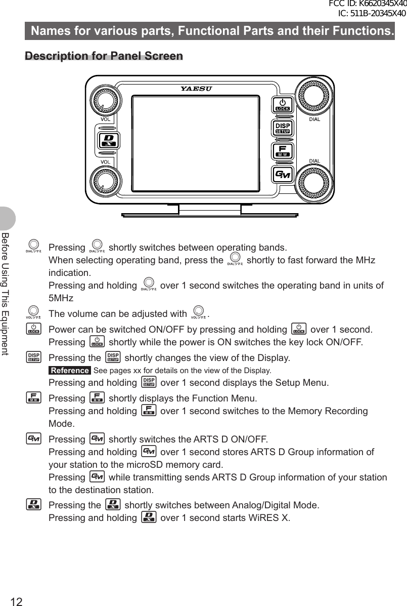
![13Before Using This EquipmentNames for various parts, Functional Parts and their Functions.Description about the Screen[V/M] Tapping [V/M] switches between VFO channels and Memory Channels.[SQL] Squelch level can be adjusted by tapping [SQL].[MUTE] Tapping [MUTE] mutes reception tone.[SCOPE] Tapping [SCOPE] switches the Band Scope Function ON/OFF.When the Band Scope Function is ON, it appears as follows:←Operating Frequency←VOL Level/SQL Level←S Meter/Destination Station Information←Band Scope AreaPressing M shortly switches to the next screen. ●ARTS/GMS Screen[BACK] Returns to the previous screen.[LIST] Displays the list of received messages.FCC ID: K6620345X40 IC: 511B-20345X40](https://usermanual.wiki/Yaesu-Musen/20345X40.User-Manual/User-Guide-1854126-Page-14.png)
![14Before Using This EquipmentNames for various parts, Functional Parts and their Functions. ●BACK TRACK Screen[Compass Unit] Tapping [Compass Unit] saves current location information.[L1] Tapping [L1] displays location information registered to L1.[L2] Tapping [L2] displays location information registered to L2.[TX] Tapping [TX] transmits the current location information/ID/TAG of your station to the destination station.[RCVD] Tapping [RCVD] selects BACK TRACK ON/OFF for the destination station. When the BACK TRACK is ON, it appears in White. When the BACK TRACK is OFF, it appears in Grey. When a signal from the destination station with it’s location information is received, it appears in orange. ●NAVIGATION Screen[Heading UP] Tapping [Heading UP] switches between Heading Up and Nose Up.[DESTINATION] Tapping [DESTINATION] displays the Point List to start navigation.[CLEAR] Tapping [CLEAR] stops navigation. [CURRENT] Tapping [CURRENT] displays the current location information.[LOCATION]The following screen appears when displaying the Point List.[BACK] Tapping [BACK] returns to the previous screen and puts the navigation on standby.[NAVI] Tapping [NAVI] returns to the previous screen and starts navigation.[EDIT] Tapping [EDIT] allows you to edit names of Point List.[DEL] Tap [DEL] allows you to delete Point List.[SORT] Tapping [SORT] sorts Point Memory in the predetermined order.FCC ID: K6620345X40 IC: 511B-20345X40](https://usermanual.wiki/Yaesu-Musen/20345X40.User-Manual/User-Guide-1854126-Page-15.png)
![15Before Using This EquipmentNames for various parts, Functional Parts and their Functions. ●ALTITUDE Screen[CLEAR] Tapping [CLEAR] deletes data being displayed.[Altitude Scale] Tapping [Altitude Scale] allows you to change measurement unit of altitude being displayed.[Distance Scale] Tapping [Distance Scale] allows you to change the measurement unit of distance being displayed.[CURRENT] Tapping [CURRENT] displays detailed location information.[LOCATION] ●TIMER/CLOCK Screen[MODE] Tapping [MODE] toggles through [CLOCK], [LAP COUNTER], [DOWN COUNTER]. ●LAP Timer Screen[START] Tapping [START] starts the Counter.[STOP] Tapping [STOP] stops the Counter.[LAP] Tapping [LAP] displays LAP value measured by Counter.[RESET] Tapping [RESET] resets LAP value measured by Counter.[RECALL] Tapping [RECALL] will display LAP value measured by Counter. ●Down Timer Screen[SETUP] Tapping [SETUP] displays setting screen for time measurement.[RESET] Tapping [RESET] returns to time measurement display screen.FCC ID: K6620345X40 IC: 511B-20345X40](https://usermanual.wiki/Yaesu-Musen/20345X40.User-Manual/User-Guide-1854126-Page-16.png)
![16Before Using This EquipmentNames for various parts, Functional Parts and their Functions. ●GPS INFO Screen[CURRENT] Tapping [CURRENT] displays detailed location information.[LOCATION MEMORY] Save present location information to memory. [1] Recieving Satellite Number [1] Signal Strength High [1] (Halftone 20%) Signal Strength Medium [1] (Halftone 50%) Signal Strength LowDescription of Microphone (MH-48)[UP] Raises the frequency up one step.[DOWN] Lowers the frequency down one step.[1] to [0] Input numbers and alphabet.[*] Switch between VFO/MEMEORY of operating band.[#] Registers frequency to memory.[A] Switches operating band to A band.[B] Switches operating band to B band.[C] Adjust DQL level.[D] Switch the view of DISPLAY.[P1] Sets SQL to OFF.[P2] Moves to frequency set as HOME.[P3] RPT SHIFT[P4] TX POWER[LOCK] Locks keys [UP] and [DOWN] to prevent miss operation.[LAMP] Lights the lamp on the Microphone.Reference• Functions for [P1] to [P4] can be changed in [OPTION] → [10 MIC PRG KEY] of the Setup Menu.FCC ID: K6620345X40 IC: 511B-20345X40](https://usermanual.wiki/Yaesu-Musen/20345X40.User-Manual/User-Guide-1854126-Page-17.png)

![19Before Using This EquipmentUsing the microSD Memory CardFormatting the microSD Memory CardFollow the instructions below when formatting a new microSD memory card.PrecautionFormatting a microSD memory card will erase all saved data. Check the data saved to the microSD memory card in use, before formatting the card.1 Press and hold M over 1 second. Set Mode screen appears.2 Tap [SD].3 Tap [1 BACKUP].4 Tap [FORMAT]. [SD CARD PUSH F KEY!] appears on screen.5 Press F. [FORMAT? PUSH F KEY!] appears on screen. Reference Tap [BACK] to cancel format.6 Press F. Formatting starts. Once format is finished, [SD CARD PUSH F KEY!] appears on screen.7 Press and hold M over 1 second. Exit from Set Mode.FCC ID: K6620345X40 IC: 511B-20345X40](https://usermanual.wiki/Yaesu-Musen/20345X40.User-Manual/User-Guide-1854126-Page-20.png)
![20Basic OperationBasic OperationCommunication1 Press and hold P over 1 second. Turn on the power.2 Adjust volume with [VOL].3 Tap [SQL]. Adjust Squelch4 Adjust frequency using O. Reference • The frequency can also be adjusted using [UP], [DOWN], and [0] to [9] on the microphone.5 Speak by pressing [PTT] on the microphone.6 Press and hold P over 1 second. Turn off the power.Reference• The type of radio is set automatically.• The type of radio can also be changed manually (See page xx).• The frequency can also be selected with the [UP] and [DOWN] on the microphone.Changing the Beep Sound.The operation confirmation sound (Beep Sound), heard when keys are operated, can be changed.1 Press and hold M over 1 second. The Setup Menu appears.2 Tap [CONFIG].3 Tap [8 BEEP] and select desired Beep Sound. The Beep Sound will change in the following order each time [8 BEEP] is tapped. [OFF] → [LOW] → [HIGH]4 Press and hold M over 1 second The Beep Sound is set and the screen returns to the previous screen.FCC ID: K6620345X40 IC: 511B-20345X40](https://usermanual.wiki/Yaesu-Musen/20345X40.User-Manual/User-Guide-1854126-Page-21.png)
![21Basic OperationCommunicationUsing the Timer FunctionThis unit is equipped with a Lap Timer and Down Timer.Precaution zAdjust the internal clock beforehand when using the timer function.(See page 000). ●Using the Lap Timer1 Press M shortly. Press M shortly until clock appears.2 Tap [MODE]. The Lap Timer appears.3 Tap [START]. The Timer starts.4 Tap [LAP]. The Lap Time is recorded every time [LAP] is tapped.5 Tap [STOP]. The Timer stops. Tapping [RESET] deletes Lap Time. Tapping [RECALL] displays Lap Time that has been recorded in the past.6 Press M shortly. Exits Timer Screen and returns to the previous screen. ●Using the Down Timer1 Press M shortly. Press M shortly a few times until clock appears.2 Tap [MODE] twice Down Timer appears.3 Tap [SETUP]. The setting screen for time measurement appears.4 Set time with O. Rotate O and set [TIME] for time measurement. Tapping [SETUP] applys the selected time. [MINUTE] can be set in the same way.FCC ID: K6620345X40 IC: 511B-20345X40](https://usermanual.wiki/Yaesu-Musen/20345X40.User-Manual/User-Guide-1854126-Page-22.png)
![22Basic OperationCommunication5 Tap [START]. The Down Timer starts. Tap [STOP] to pause timer if you want to stop it in the middle. When the set time is reached, [00:00’00] appears in green.6 Press M shortly. Exits Timer Screen and returns to the previous screen.The ALTITUDE function for measuring altitude.The altitude of present location or change of altitude according to traveled distance can be displayed as a graph.Precaution zIn order to use the ALTITUDE function, connect the optional GPS antenna unit. zIn order to display the ALTITUDE screen, set to [ALTITUDE:ON] of [DISPLAY] → [1 DISPAY SELECT] in the Top Menu beforehand.1 Press M shortly. Press M shortly a few times until ALTITUDE screen appears.2 Altitude appears. The present altitude appears on the display. Tapping [CLEAR] deletes accumulated data of altitude change. Tapping [LOCATION MEMORY] saves information on present location.3 Press M shortly. Press M shortly a few times until the screen returns to the previous one.Locking Keys and SwitchesOand switches can be locked to prevent accidental changes in radio frequency during movement.1 Press P shortly. [LOCK] appears on the display and the screen returns to the previous one. Reference To Unlock, press [PTT] shortly again. [UNLOCK] appears on the display and the screen will return to the previous one.Reference• Conditions for automatic Lock can be changed in the Setup Menu (See page 000).FCC ID: K6620345X40 IC: 511B-20345X40](https://usermanual.wiki/Yaesu-Musen/20345X40.User-Manual/User-Guide-1854126-Page-23.png)
![23Basic OperationSwitching type of radio (mode) and conducting communicationIn factory settings, this unit is set in [AUTO] mode and automatically selects the optimum mode (type of radio) according to frequency. The type of radio (mode) can be manually changed and conduct communication.Using this unit, communication can be conducted in 4 forms: [AUTO (FM)], [FM], [NARROW FM], and [AM].Select the desired mode and conduct communication with the following steps.1 Press and hold M over 1 second. The Setup Menu appears.2 Tap [TX/RX].3 Tap [MODE] and select desired Mode. The Mode changes in the following order each time [MODE] is tapped.[AUTO (FM)]: Automatically switches to the optimal type of radio according to frequency band.[FM]: Only changes the selected frequency band to FM Mode.[Narrow FM]: Only changes the selected frequency band to NFM Mode.[AM]: Only changes the selected frequency band to AM Mode. Reference Mode can also be selected by pressing v.5 Press and hold M over 1 second. The Mode is set and the screen returns to the previous one.6 Set frequency with O. Select frequency for communication.7 Speak by pressing [PTT] on the microphone. Speak with about 5cm between microphone and mouth.8 Release [PTT]. Returns to reception state.FCC ID: K6620345X40 IC: 511B-20345X40](https://usermanual.wiki/Yaesu-Musen/20345X40.User-Manual/User-Guide-1854126-Page-24.png)
![24Basic OperationSwitching type of radio (mode) and conducting communicationChanging Transmission OutputThe transmission output can be lowered for when communicating with a transceiver near by, or to reduce battery consumption.1 Press F.2 Tap [Tx PWR] and select desired transmission output. The Transmission Output changes in the following order, each time [Tx PWR] is tapped. [HI (5.0W)] → [LOW (OOW)] → [MID (OOW)] Reference • Sensitivity can also be selected by pressing O.Reference• Avoid long periods of continuous transmission. Doing so causes temperature of the unit to rise, and may lead to malfunction or burning injuries due to over heating.• The current Output level is indicated under [Tx PWR] on the display.• [OFF] appears on the display for frequencies where signal cannot be transmitted.• This unit is set to [HI] in Factory setting.Adjusting Microphone Sensitivity (MIC GAIN)The Microphone Sensitivity can be adjusted.1 Press and hold M over 1 second. The Setup Menu appears.2 Tap [TX/RX].3 Tap [AUDIO].4 Tap [3 MIC GAIN] and select desired Sensitivity. The Sensitivity changes in the following order each time [3 MIC GAIN] is tapped. [MIN] → [LOW] → [NORMAL] → [HIGH] → [MAX] Reference • Sensitivity can also be selected by pressing the O. • Factory Setting: NORMAL5 Press and hold M over 1 second. The MIC GAIN is set and the screen returns to the previous one.FCC ID: K6620345X40 IC: 511B-20345X40](https://usermanual.wiki/Yaesu-Musen/20345X40.User-Manual/User-Guide-1854126-Page-25.png)
![25Basic OperationOther SettingsAdjusting TimeThis Unit is equipped with an internal clock. Not only does this clock display time, but also has a timer for automatically turning power ON and OFF at times set by the user. Adjust the time before using this function.1 Press and hold M over 1 second. Setup Mode appears.2 Tap [CONFIG].3 Tap [1 DATA & TIME ADJUST]. [DATA & TIME ADJUST] screen appears.4 Tap [SET]. The cursor moves to [MONTH].5 Set Month. Tap [+] or [–] to select Month.6 Tap [SET]. The cursor moves to [DAY].7 Set Day. Tap [+] or [–] to select Day.8 Tap [SET].9 Repeat Step 5 to Step 6. Set [YEAR], [HOUR], [MINUTE].10 Press and hold M over 1 second. The Date is set and the screen returns to the previous one. Note The Date/Time appears in the upper right corner of the screen.Reference• The accuracy of the clock is within 30 seconds per month at room temperature. The accuracy varies depending on the use conditions such as temperature. • The accuracy may degrade when the battery is low or if it is the first time using this unit. Readjust the time under these circumstances.• The calendar can display dates from January 1st, 2000 A.D. to December 31st, 2099 A.D.FCC ID: K6620345X40 IC: 511B-20345X40](https://usermanual.wiki/Yaesu-Musen/20345X40.User-Manual/User-Guide-1854126-Page-26.png)
![26Basic OperationOther SettingsMuting SoundsIf the sounds from A Band and B Band overlap and become difficult to hear during Dual frequency reception, the sound for bands other than operating band can be muted.1 Press and hold M over 1 second. The Setup Menu appears.2 Tap [TX/RX].3 Tap [AUDIO].4 Tap [2 SUB BAND MUTE] and select Mute ON. Mute is switched [ON] and [OFF] each time [2 SUB BAND MUTE] is tapped. Reference • Mute can also be selected by pressing the O.5 Press and hold M over 1 second. The Mute ON is set and the screen returns to the previous one.ReferenceTap [MUTE] displayed on the bottom of the screen to switch the Mute Function to OFF.Mute is switched [ON] and [OFF] each time [MUTE] is tapped.Adjusting Squelch LevelYou can mute the raspy noise heard when no signal is being received. The squelch level can be adjusted separately for two broadcasts (NFM and AM) received on the A-band and B-band. When the squelch level is increased, the noise is more liable to disappear but, in some cases, it becomes difficult to receive weak signals. Adjust the squelch level as required.1 Tap [SQL].2 Adjust Squelch level with O. Adjust the Squelch level by rotating the upper O for A Band, and lower O for B Band. Reference • Squelch level can be adjusted from 0 to 8. • Factory Setting: Level 13 Tap [SQL]. The Squelch level is set and the screen returns to the previous one.FCC ID: K6620345X40 IC: 511B-20345X40](https://usermanual.wiki/Yaesu-Musen/20345X40.User-Manual/User-Guide-1854126-Page-27.png)
![27Basic OperationOther SettingsManually switching frequency stepsIn factory settings, this unit is set to [AUTO (Step)] mode and automatically selects the optimum frequency step according to reception frequency. These frequency steps can be manually changed.1 Press and hold M over 1 second. The Setup Menu appears.2 Tap [CONFIG].3 Tap [7 FM AM STEP] and select [AUTO]. [AUTO] appears in orange.4 Set frequency with O. The frequency step changes in the following order, each time O is rotated. [AUTO] → [5.00KHz] → [6.25KHz] → [10.00KHz] → [12.50KHz] → [15.00KHz] → [20.00KHz] → [25.00KHz] → [50.00KHz] → [100.00KHz] Reference Mode can also be selected by pressing the v.5 Tap [7 FM AM STEP]. The selected frequency changes from orange to green and set as current setting.6 Press and hold M over 1 second. The frequency step is set and the screen returns to the previous one.Resetting applied settingsSettings and memory content can be returned to factory settings.1 Press and hold M over 1 second. The Setup Menu appears.2 Tap [RESET/CLONE]. Reset screen appears.3 Tap items to reset. Select items to reset.[1 FACTORY RESET]: Returns all applied setting to factory settings.[2 PRESET]: Registers the preset screen.[3 RECALL PRESET]: Displays the preset screen.[4 MEM CH RESET]: Erases only the registered memory channels. * Settings applied in the Setup Menu are not erased.[5 MEM CH SORT]: Sorts memory registered to A/B Bands.[6 ARPS RESET]: Returns setting for ARPS to factory settings.[7 CLONE]: Copy settings of this unit to another transceiver.4 Tap [OK?] Settings and memory are reset and returned to factory settings. Reference Tap [Cancel] to cancel Resetting.FCC ID: K6620345X40 IC: 511B-20345X40](https://usermanual.wiki/Yaesu-Musen/20345X40.User-Manual/User-Guide-1854126-Page-28.png)
![28Repeater OperationRepeater OperationRepeater OperationCommunicating Via the RepeaterFTM-400DR supports an ARS (Automatic Repeater Shift) function which allows you to perform communication automatically just by setting the reception frequency to the repeater frequency (439.000 to 440.000 MHz).1 Set the reception frequency to repeater frequency.2 Perform transmission while pressing [PTT]. During transmission, a 88.5Hz tone signal and a radio wave whose frequency is 5 MHz lower than the reception frequency are emitted.Reference• Pressing F and then taping [REV] produces the “reverse” state where the transmission frequency and the reception frequency are temporarily reversed, allowing you to check whether you can communicate with the remote station directly.• The [ ] on the display blinks while in the “REVERSE” state.• Pressing F then tapping [REV] again cancels the “REVERSE” state.• Press and hold M over 1 second to change the Setup Menu. This allows you to use the repeater more conveniently.[CONFIG] → [4 AUTO RPT SHIFT] You can deactivate the ARS function.[CONFIG] → [5 RPT SHIFT] You can set the repeater shift direction.[CONFIG] → [6 RPT SHIFT FREQ] You can change the repeater shift step.Communicating Via the Repeater Using a Tone Signal Other Than the 88.5Hz Tone Signal1 Set the reception frequency to repeater frequency.2 Press and hold M over 1 second.3 Tap [CONFIG].4 Tap [5 RPT SHIFT] and select [–]. Switches between [OFF] → [–] → [+] each time [5 RPT SHIFT] is tapped. Reference • Factory Setting: OFF5 Tap [6 RPT SHIFT FREQ]. The frequency appears in orange.6 Set frequency with O. Rotate the O and select the desired tone frequency.7 Tap [6 RPT SHIFT FREQ]. The selected frequency will change from orange to green and be applied as the current setting. Reference • Frequency can also be selected by pressing the O.FCC ID: K6620345X40 IC: 511B-20345X40](https://usermanual.wiki/Yaesu-Musen/20345X40.User-Manual/User-Guide-1854126-Page-29.png)
![29Repeater OperationRepeater Operation8 Press and hold M over 1 second. The tone frequency is set and the screen returns to the previous one.9 Perform transmission while pressing [PTT]. During transmission, the tone signal that has been set and radio wave whose frequency is 5 MHz lower than the reception frequency are emitted.ReferenceThe settings can be stored in the memory. (Storing in the memory (See page 000)).FCC ID: K6620345X40 IC: 511B-20345X40](https://usermanual.wiki/Yaesu-Musen/20345X40.User-Manual/User-Guide-1854126-Page-30.png)
![30Using MemoryUsing MemoryWide variety of Memory FunctionsFTM-400DR provides the following various types of memory channels in addition to the regular memory channels (500 channels each for both A and B band. • [Skip Search Memory] that allow you to skip unwanted frequencies during VFO scanning. • 9 sets of [memory channels for Programmable Memory Scanning (PMS)] respectively for both A band and B band.An operating frequency, operation mode (type of radio), and other operational information can be stored for each regular memory channel, or PMS memory channel.• Operating frequency • Operation mode • Memory tag• Repeater information • Tone information • DCS information• Antenna squelch information • Memory skip information • Transmission OutputRegistering to MemoryPrecautionContent stored in memory can be erased due to incorrect operation, static electricity, or electrical noise. Memory content can also be erased during malfunction or repair. Content that is stored in memory should be written on paper or backed up on a microSD memory card.The FTM-400DR allows you to use 500 memory channels respectively for both A band and B band.1 Switch to VFO mode.2 Select frequency with O. Select the frequency to register to the memory.3 Press and hold F over 1 second. The register to memory screen appears.4 Tap [MW]. The character entry screen appears. Reference Memory can also be named (See page 000).5 Tap [ENT]. The memory write operation is completed, and the registered frequency appears on screen. Reference Tap [Cancel] to cancel registering to memory.Reference• 145.000MHz is registered to memory channel 1 in factory settings. Although this frequency can be changed, it cannot be erased.• The frequency which has previously been registered to a memory channel can be overwritten with a new frequency.When you intend to register a new frequency into the memory, an unregistered memory channel is displayed.FCC ID: K6620345X40 IC: 511B-20345X40](https://usermanual.wiki/Yaesu-Musen/20345X40.User-Manual/User-Guide-1854126-Page-31.png)
![31Using MemoryWide variety of Memory FunctionsSplit MemoryTwo different frequencies, one for reception and other for transmission can be registered to a memory channel.1 Register reception frequency to the memory. Reference Refer to the [Registering to Memory] above, for registering frequency.2 Select transmission frequency in VFO mode.3 Press F for longer than a second. The register to memory screen appears.4 Tap [Reception Frequency]. Select the reception frequency to spcify from the memory list.5 Tap [TX IN]. The character entry screen appears. Reference The radio frequency can also be named (See page 000).6 Tap [ENT]. Registration to memory completes and the frequency appears on screen. When you recall the memory channel of which you registered two different frequencies, one for reception and the other for transmission, the @ icon appears on screen.Recalling a Memory ChannelRecall a registered memory channel in the following procedure:1 Tap [V/M]. The Memory mode is selected, and the memory channel you used last appears on screen.2 Select a memory channel with O. Select the memory channel to use. Remark • Pressing and holding O over 1 second skips channels quickly in step of 10 channels. Tapping [V/M] againreturns to VFO Mode.Reference• Unregistered memory channels are skipped.• By default, the priority memory channel used as the priority channel for the dual receive function was set to the memory channel 1. “P” appears at the upper right of the memory channel number (See page 000).FCC ID: K6620345X40 IC: 511B-20345X40](https://usermanual.wiki/Yaesu-Musen/20345X40.User-Manual/User-Guide-1854126-Page-32.png)
![32Using MemoryWide variety of Memory FunctionsRecalling the Home Channel1 Press D shortly. Home Channels appear on screen. Reference • Selecting the frequency with O returns to VFO Mode.Returning to the Previous Frequency1 Press D shortly. The frequency selected before recalling the home channel appears on screen. ●Changing a Home Channel FrequencyYou can change a default home channel frequency.1 Switch to VFO mode.2 Set frequency with O.3 Press and hold F over 1 second. Write to memory screen appears.4 Tap [▲] or [▼] and select [HOME]. It can also be selected by pressing O.5 Tap [MW]. The character entry screen appears. Reference The radio frequency can also be named (See page 000).6 Tap [ENT]. Writing to memory l completes and the changed frequency appears on screen.Deleting Memory1 Press M 1M for longer than a second. The Setup Menu appears.2 Tap [MEMORY].3 Tap [3 MEM EDIT]. Reference It can also be selected by pressing O.4 Tap the memory to delete.5 Tap [DEL]. The deletion confirmation screen appears.6 Tap [OK?]. Memory is deleted. Reference • Tapping [Cancel] cancels deletion. • To continue deleting memory, repeat steps 4 through 6.7 Press and hold M over 1 second. Returns to the previous screen.FCC ID: K6620345X40 IC: 511B-20345X40](https://usermanual.wiki/Yaesu-Musen/20345X40.User-Manual/User-Guide-1854126-Page-33.png)
![33Using MemoryWide variety of Memory FunctionsPrecaution zMemory channel 1 cannot be deleted.ReferenceThe memory channel specified as a home channel cannot be deleted. Before deleting it, specify another memory channel as a home channel.Changing the display method of Memory Tags.The display method of name and frequency assigned to memory tags can be changed.1 Switch to Memory Mode. Display a memory channel to change the display method for the memory tag.2 Press and hold M over 1 second. The Setup Menu appears.3 Tap [MEMORY].4 Tap [2 ALPHA TAG SIZE] and select size. Size switches between [SMALL] and [LARGE] each time [2 ALPHA TAG SIZE] is tapped.5 Press and hold M over 1 second. The selected size is set and the screen returns to the previous one. Reference Factory Setting: SMALLFCC ID: K6620345X40 IC: 511B-20345X40](https://usermanual.wiki/Yaesu-Musen/20345X40.User-Manual/User-Guide-1854126-Page-34.png)
![34Scanning FunctionScanning FunctionUsing the Scanning FunctionThe FTM-400DR supports the following four scan modes:(1) VFO Scan(2) Memory Scan(3) Programmable Memory Scan(4) Selected Memory Channel ScanVFO Scan1 Switch to the VFO mode, and then select a band to scan.2 Press F shortly. The Function Menu appears.3 Tap [SCAN]. Scanning (SCAN) starts toward higher frequencies. Reference • Pressing and holding [UP] or [DOWN] over 1 second also starts scanning. • When a signal is received during scanning, a beep is emitted and scanning pauses for 5 seconds and then resumes. • The scan direction (HIGH/LOW) can be set in the [SCAN] → [2 SCAN DIRECTION] of the Setup Menu. • The operation to perform when scanning stops can be set in the [SCAN] → [3 SCAN RESUME] of the Setup Menu.Canceling ScanningTo chancel scanning, tap [SCAN] or [PTT] on the microphone.Reference• For the operation to perform when scanning stops, see “Setting a Reception Method When Scanning Stops” on page (See page 000).Setting a Reception Method When Scanning StopsWhen scanning stops, you can select one of the following three reception methods:(1) The signal is received for the specified period of time, and then scanning resumes. You can specify this period of time to 1 second, 3 seconds, or 5 seconds.(2) The signal is received until it fades out. Two seconds after the signal fades out, scanning resumes. “BUSY” appears on screen.(3) Scanning stops and the current frequency is received. “HOLD” appears on screen.FCC ID: K6620345X40 IC: 511B-20345X40](https://usermanual.wiki/Yaesu-Musen/20345X40.User-Manual/User-Guide-1854126-Page-35.png)
![35Scanning FunctionUsing the Scanning Function1 Press and hold M over 1 second. The Setup Menu appears.2 Tap [SCAN].3 Tap [3 SCAN RESUME] and select desired reception method. The reception method changes in the following order each time [3 SCAN RESUME] is tapped. [BUSY] → [HOLD] → [1sec] → [3sec] → [5sec] Reference • It can also be selected by pressing O. • Factory Setting: 5 seconds4 Press and hold M over 1 second. The reception method when scanning stops is set and the screen returns to the previous one.Reference• The reception method selected here is also applied to [VFO Scanning], [Programmable Memory Scanning], [Memory Scanning], and [Dual Reception].Memory ScanningFrequencies registered to the memory can be scanned in the order of memory channel number.1 Switch to Memory mode and recall a memory channel.2 Press F shortly. The Function Menu appears.3 Tap [SCAN]. Scanning (SCAN) is performed toward higher memory channel numbers. When a signal is received during scanning, a beep is emitted and scanning pauses for 5 seconds and then resumes. Reference • Pressing and holding [UP] or [DOWN] over 1 second also starts scanning. • To stop scanning, tap [SCAN] or [PTT] on the microphone.Reference• Even during scanning, you can adjust the squelch by tapping [SQL].Tapping [SQL] again terminates squelch adjustment.• For the operation to perform when scanning stops, see “Setting a Reception Method When Scanning Stops” on page (See page 000).FCC ID: K6620345X40 IC: 511B-20345X40](https://usermanual.wiki/Yaesu-Musen/20345X40.User-Manual/User-Guide-1854126-Page-36.png)
![36Scanning FunctionUsing the Scanning Function ●Setting the Scan Method.The scanning method to scan all memory channels or only selected memory channels can be set in the Setup Menu. • ALL MEM: Scans all memory channels • SELECT MEM: Only scans selected memory channels1 Press and hold M over 1 second. The Setup Menu appears.2 Tap [MEMORY].3 Tap [MEM SCAN TYPE] and then select [SELECT MEM]. The scanning method switches between [ALL MEM] and [SELECT MEM] each time [MEM SCAN TYPE] is tapped. Reference • The scanning method can also be selected by pressing the O.4 Press and hold M over 1 second. The scanning method is set and the screen returns to the previous one. ●Specifying a Skip/Selected Memory ChannelYou can specify two types of memory channels to scan: memory channels to skip and selected memory channels to scan, for effective memory scanning.Skip memory channel: You can specify memory channels that need not be scanned during memory scanning.Selected memory channel: When [MEM SCAN TYPE] is set to [SELECT MEM], only the specified memory channels are scanned during memory scanning.Memory channels to skip and selected memory channels to scan can be specified in the 2 methods following.(1) Collectively select memory channels in the Memory Write screen.(2) Individually select memory channels when scanning.(1) Collectively specifying memory channels in the Memory Write screen.1 Press and hold F over 1 second. The Memory Write screen appears.2 Tap the memory to select. Select memory by tapping it.3 Tap [SKIP/SEL]. The scanning method switches between [SKIP], [SELECT], and [OFF], each time [SKIP/SEL] is tapped. Reference • The scanning method can also be selected by pressing the O. • To continue selecting memory channels, repeat steps 2 through 3.FCC ID: K6620345X40 IC: 511B-20345X40](https://usermanual.wiki/Yaesu-Musen/20345X40.User-Manual/User-Guide-1854126-Page-37.png)
![37Scanning FunctionUsing the Scanning Function5 Press and hold F over 1 second. Returns to the previous screen.(2) Individually select memory channels when scanning1 Switch to Memory mode and then recall the memory channels to specify as memory channels to skip or selected memory channels to scan.2 Press F shortly. The Function Menu appears.3 Tap [SKIP/SEL] and set [SKIP] or [SEL]. The scanning method switches between [SKIP] and [SEL] each time [SKIP/SEL] is tapped. Reference • The scanning method can also be selected by pressing the O.4 Press F shortly. The memory channels to skip/selected memory channels to scan are set and the screen returns to the previous one. ●Scanning only memory channels selected in the specified memory.1 Switch to Memory mode and then recall the memory channels selected for scanning.2 Tap [SCAN]. Only the memory channels selected in the specified memory are scanned. Reference • Pressing and holding [UP] or [DOWN] over 1 second also starts scanning. • Scanning (SCAN) is performed toward higher memory channel numbers. • When a signal is received during scanning, a beep is emitted and scanning pauses for 5 seconds and then it’s frequency is recieved. • To cancle scanning, tap [SCAN] or [PTT] on the microphone.Programmable Memory Scan (PMS)Writing into a Programmable Memory9 sets of PMS memory channels (L1/U1 to L9/U9) are available.Specify the lower limit frequency of the frequency range you want to san for “L½”, and the upper limit frequency for “U½”.Enter a number between 1 and 9 for “½”. Use the same number for the lower and upper limit.FCC ID: K6620345X40 IC: 511B-20345X40](https://usermanual.wiki/Yaesu-Musen/20345X40.User-Manual/User-Guide-1854126-Page-38.png)
![38Scanning FunctionUsing the Scanning Function1 Switch to VFO mode.2 Select a frequency with O. Select a frequency for the lower limit. Caution • Make sure to set the frequency set for the lower limit (P1L) lower than the frequency set as the upper limit (P1U).3 Press and hold F over 1 second. Memory Write screen appears.4 Tap [▲] or [▼] to select [P1L]. It can also be selected by pressing O.5 Tap [MW]. The character entry screen appears. Reference The radio frequency can also be named (See page 000).6 Tap [ENT].7 Set frequency with O. Select a frequency for the upper limit.8 Press and hold F over 1 second.9 Tap [▲] or [▼] to select [P1U]. It can also be selected by pressing O.10 Tap [MW]. The character entry screen appears. Reference The radio frequency can also be named (See page 000). Writing to the programmable memory ends and the screen returns to the previous one.Example: Specification of the lower limit frequency “433.200 MHz” and the upper limit frequency “433.700 MHz” for PMSLower limit: L1 Upper Limit: U1PrecautionThe difference between the upper limit frequency and the lower limit frequency for PMS must be 100 kHz or more.FCC ID: K6620345X40 IC: 511B-20345X40](https://usermanual.wiki/Yaesu-Musen/20345X40.User-Manual/User-Guide-1854126-Page-39.png)
![39Scanning FunctionUsing the Scanning FunctionPerforming Programmable Memory ScanThe programmable memory allows you to scan the specified frequency range in the same frequency band.1 Switch to Memory mode. Recall the PMS memory storing the lower limit frequency or upper limit frequency.2 Press F shortly. 3 Tap [SCAN]. Programmable memory scanning starts. Reference • Pressing and holding [UP] or [DOWN] over 1 second also starts scanning. • When a signal is received during scanning, scanning pauses for 5 seconds. • The scanning resumes 5 seconds after signal has been received. • To cancel scanning, tap [SCAN] or [PTT] on the microphone.Precaution zWhen the lower/upper limit frequency is not properly specified, program memory scanning is not performed properly.Reference• If PMS memory channels have already been assigned to L1/U1 to L9/U9, selecting a PMS number in the VFO scanning procedure described on page 56 allows you to skip step 1 described above.• When a skip memory (½½) is specified for “L½” or “U½” or when the lower/upper limit frequency is not properly specified, program memory scanning is not performed properly.• Even during scanning, you can adjust the squelch in the following procedure:Tap [SQL] → Adjust squelch with v → Tap [SQL]FCC ID: K6620345X40 IC: 511B-20345X40](https://usermanual.wiki/Yaesu-Musen/20345X40.User-Manual/User-Guide-1854126-Page-40.png)
![40Scanning FunctionSearching for a Signal Using a Signal Strength Graph Band Scope FunctionDuring mono band reception in the VFO mode, use states of channels (strengths of channel signals) around the current frequency set as center [▼] can be graphically displayed on screen.1 Tap [V/M]. The mode switches to Mono Band.2 Tap [SCOPE]. The SCOPE screen appears.3 Turn the O knob to move the ▼ icon to the signal position. The signal at the center frequency can be received.4 Tap [SCOPE]. The Band Scope is deactivated.Reference• When band scope channel is ± 5, numeric values representing signal strengths are displayed in the graph.• The band scope channel interval is the same as the VFO frequency step.• The band scope channel interval can be changed in Setup Menu, [Display] → [3 BAND SCOPE].FCC ID: K6620345X40 IC: 511B-20345X40](https://usermanual.wiki/Yaesu-Musen/20345X40.User-Manual/User-Guide-1854126-Page-41.png)
![41Useful FunctionsUseful FunctionsDual Reception (DW) FunctionsThis FTM-400DR supports the following two dual reception functions:(1) Dial dual reception(2) Memory dual receptionThe signal of the specified memory channel (Home Channel) is checked at intervals of about 5 seconds. If this signal is detected, it is received.Example: Checking Home Channel while receiving [145.500MHz].Frequency being receivedThe signal of the Home Channel is checked at intervals of about 5 seconds.If the signal of the Home Channel is received, the decimal point blinks.Dial Dual ReceptionVFO mode → Home channel1 Adjust to frequency desired for reception. Adjust to the frequency to receive using O knob.2 Press F shortly. The Function Menu appears.3 Tap [DW]. If [DW] is not displayed in the Function menu, tap [NEXT].4 Dual reception starts. The signal of home channel is received around every 5 seconds. When a signal of the home channel is received, the frequency changes to that of the home channel. To cancel the dual reception, press F shortly again and tap [DW].FCC ID: K6620345X40 IC: 511B-20345X40](https://usermanual.wiki/Yaesu-Musen/20345X40.User-Manual/User-Guide-1854126-Page-42.png)
![42Useful FunctionsDual Reception (DW) FunctionsMemory Dual ReceptionMemory channel → Home Channel1 Switch to Memory Mode.2 Adjust to the memory channel to recieve. Adjust to the memory channel to receive using O knob.3 Press F shortly. The Function Menu appears.4 Tap [DW]. If [DW] is not displayed in the function menu, tap [NEXT].5 Dual reception starts. The signal of home channel is received around every 5 seconds. When a signal of the home channel is received, the frequency changes to that of the home channel. To cancel the dual reception, press F shortly again and tap [DW].Precaution zMake sure to set home channel prior to using memory dual reception.Reference• If a signal of dual reception is received , it’s frequency is received for 5 seconds and then dual reception resumes. Even while receiving the home channel, dual reception can be canceled by pressing [PTT] on the microphone and can perform transmission using that frequency.• The operation to perform when dual reception is running can be set in the [SCAN] → [1 DUAL WATCH STOP] of the Setup Menu.Using the DTMF Function.“DTMF (Dual Tone Multi Frequency) tones” refer to the tones (beep boop beep) heard from the receiver of the push-button phone. You can register the telephone number for phone patch connection to the public telephone line, etc. with a DTMF code comprising up to 16 characters (for up to 9 channels).1 Press ad hold M over 1 second. The Setup Menu appears.2 Tap [SIGNALING].3 Tap [4 DTMF MEMORY]. The DTMF Memory screen appears. Reference This can also be selected by pressing the O.FCC ID: K6620345X40 IC: 511B-20345X40](https://usermanual.wiki/Yaesu-Musen/20345X40.User-Manual/User-Guide-1854126-Page-43.png)
![43Useful FunctionsUsing the DTMF Function.4 Tap a channel to select. Select a number (1-9) to which the DTMF code is to be registered.5 Tap the DTMF Code to register. Tap the numerical keypad and enter the DTMF code o register. Reference • The DTMF code can also be entered using the numerical keypad on the Microphone. • Tap [Cancel] if an incorrect number is entered.6 Tap [ENT]. The DTMF code is registered to the selected number.7 Press and hold M over 1 second. Returns to the previous screen.Sending the Registered DTMF Code1 Press and hold M over 1 second. The Setup Menu appears.2 Tap [SIGNALING].3 Tap [3 AUTO DIALER] and select [ON]. Tapping [3 AUTO DIALER] switches between [ON] and [OFF]. Reference This can also be selected by pressing the O.4 Press and hold M over 1 second. Returns to the previous screen.5 Press F shortly. The Function Menu appears.6 Tap [DTMF]. If [DTMF] is not displayed in the function menu, tap [NEXT]. Tapping [DTMF] switches through registered DTMF Codes.7 Press F shortly. Returns to the previous screen.8 Press [PTT]. Pressing [PTT] on the Microphone automatically sends DTMF code.9 Release [PTT]. Even after [PTT] on the microphone is released, sending of the DTMF signal continues until it is completed.FCC ID: K6620345X40 IC: 511B-20345X40](https://usermanual.wiki/Yaesu-Musen/20345X40.User-Manual/User-Guide-1854126-Page-44.png)
![44Useful FunctionsSending a DTMF Code Manually1 Press and hold M over 1 second. The Setup Menu appears.2 Tap [SIGNALING].3 Tap [3 AUTO DIALER] and select [OFF]. Tapping [3 AUTO DIALER] switches between [ON] and [OFF].4 Press and hold M over 1 second. Returns to the previous screen.5 Select a number from [1] through [9] while pressing [PTT] Tap the numerical keypad and enter the DTMF code to send.6 Release [PTT]. Even after [PTT] on the microphone is released, sending of the DTMF signal continues until it is completed.Reference• A DTMF code is a combination of two frequencies.1209Hz 1336Hz 1477Hz 1633Hz697Hz 1 2 3 A770Hz 4 5 6 B852Hz 7 8 9 C941Hz ½0#DFCC ID: K6620345X40 IC: 511B-20345X40](https://usermanual.wiki/Yaesu-Musen/20345X40.User-Manual/User-Guide-1854126-Page-45.png)
![45Communicating with a Specific Remote StationCommunicating with a Specific Remote StationUsing the Tone Squelch FunctionThe tone squelch opens the squelch only when a signal containing the specified frequency tone is received. Use of the digital code squelch (DCS) opens the squelch only when a signal containing the specified DCS code is received. The tone squelch function blocks monitoring of communications between other stations even when waiting for call by a specific station for a long time.1 Press F shortly. The Function Menu appears.2 Tap [SQL] to select a squelch type. The squelch type changes in the following order each time [SQL] is tapped: [NOISE] → [T-TX] → [T-TRX] → [T-REV] → [D-TRX PRGM] → [PAGER] → [JR] →[D-TX] → [TT/DR] → [DT/TR] The display for [SQL] changes according to the selected squelch type.3 Press F shortly. The squelch type is set and the screen returns to the previous one.Reference• The tone squelch setting or the DCS setting is also effective for scanning. If scanning is performed with the tone squelch or the DCS function turned on, it stops only when a signal containing a tone of the specified frequency or a signal containing the specified DCS code is received.Display Operation NOISE XXXXXXXXXXXXXXXXXXXXXXXXXXXXXXXXXXX.T-TX XXXXXXXXXXXXXXXXXXXXXXXXXXXXXXXXXXX.T-TRX XXXXXXXXXXXXXXXXXXXXXXXXXXXXXXXXXXX.T-REV XXXXXXXXXXXXXXXXXXXXXXXXXXXXXXXXXXX.D-TRX PRGM XXXXXXXXXXXXXXXXXXXXXXXXXXXXXXXXXXX.PAGERTurns on a new pager function (“PAG” appears).When using FTM-400DR with your friends, specifying personal codes (each code is composed of two tones) allows calling a specific station.JRTurns on the no-communication squelch function of the JR radio (“JR” appears).Mutes the 2280 MHz no-communication signal tone which is heard when no communication is performed. D-TX XXXXXXXXXXXXXXXXXXXXXXXXXXXXXXXXXXX.TT/DR XXXXXXXXXXXXXXXXXXXXXXXXXXXXXXXXXXX.DT/TR XXXXXXXXXXXXXXXXXXXXXXXXXXXXXXXXXXX.FCC ID: K6620345X40 IC: 511B-20345X40](https://usermanual.wiki/Yaesu-Musen/20345X40.User-Manual/User-Guide-1854126-Page-46.png)
![46Communicating with a Specific Remote StationUsing the Tone Squelch FunctionSelecting a Tone FrequencyThe Tone frequency can be selected from 50 frequencies between 67.0Hz to 254.1Hz.1 Select the operating frequency.2 Press and hold M over 1 second. The Setup Menu appears.3 Tap [SIGNALING].4 Tap [1 TONE SQL FREQ]. The tone frequency appears in orange.5 Select a frequency with the O.6 Press O shortly. The tone frequency is set and it appears in green.7 Press and hold M over 1 second. Returns to the previous screen.Reference• The tone frequency set using the above-described procedure is also effective when only the tone is sent out.• By default, the tone frequency is set to 88.5Hz.Searching for the Frequency of the Tone Squelch Used by the Remote StationThe frequency of the tone squelch used by the remote station can be searched for and displayed.1 Press F shortly. The Function Menu appears.2 Tap [SQL] and select [T-TRX]. Tap until the [SQL] display switches to [T-TRX].3 Press F shortly.4 Tap [SQL]. Search for the tone frequency starts. When a coincident frequency is detected, a beep is emitted and search stops temporarily. The detected tone frequency blinks.Reference• For the operation to perform when scanning stops, see “Selecting a Reception Method When Scanning Stops” on page (See page 000). FCC ID: K6620345X40 IC: 511B-20345X40](https://usermanual.wiki/Yaesu-Musen/20345X40.User-Manual/User-Guide-1854126-Page-47.png)
![47Communicating with a Specific Remote StationUsing the Tone Squelch FunctionSelecting a DCS CodeYou can select a DCS code from among 104 DCS codes (023 to 754).1 Selecting the operating frequency.2 Press and hold M over 1 second. The Setup Menu appears.3 Tap [SIGNALING].4 Tap [2 DCS CODE]. The DCS code number appears in orange.5 OSelect DCS code number with the O.6 OPress O shortly. The DCS code is set and DCS code number appears in green.7 Press and hold M over 1 second. Returns to the previous screen.Reference• By default, the DCS code is set to “023”.Searching for the Frequency of the DCS Used by the Remote StationThe DCS code used by the remote station can be searched for and displayed.1 Press F shortly. The Function Menu appears.2 Tap [SQL] and select [D-TRX]. Tap until the [SQL] display switches to [D-TRX].3 Press F shortly.4 Tap [SQL]. Search for the DCS code starts. When a coincident DCS code is found, a beep is emitted and search stops temporarily. The found DCS code blinks.Reference• For the operation to perform when scanning stops, see “Selecting a Reception Method When Scanning Stops” on page (See page 000).FCC ID: K6620345X40 IC: 511B-20345X40](https://usermanual.wiki/Yaesu-Musen/20345X40.User-Manual/User-Guide-1854126-Page-48.png)
![48Communicating with a Specific Remote StationNotification of Call from a Remote Station by the BellCall from a remote station (reception of a signal containing a coincident tone or DCS) can be notified by the bell sound and the b icon blinking on on screen.1 Press and hold M over 1 second. The Setup Menu appears.2 Tap [SIGNALING].3 Tap [7 BELL RINGER]. The set value for BELL RINGER appears in orange.4 Turn the O to select a number of times the bell rings. The number of times the bell rings changes in the following order, each time O is rotated. [OFF] → [1time] → [3times] → [5times] → [8times] → [CONTINUE]5 Press O shortly. The number of times the bell rings is set and appears in green.6 Press and hold M over 1 second. Returns to the previous screen.Calling Only a Specific Station New Pager FunctionWhen using FTM-400DR with your friends, specifying personal codes (each code is composed of two CTCSS codes) allows only a specific station to be called. Even if the called person is not near his or her FTM-400DR, the information on the screen indicates that he or she has been called.Flow of Operation to Use the Pager FunctionSet the same code as that of the remote station.Determine a frequency.Perform transmission/reception.Confirm reception according to the information on the screen and the bell soundFCC ID: K6620345X40 IC: 511B-20345X40](https://usermanual.wiki/Yaesu-Musen/20345X40.User-Manual/User-Guide-1854126-Page-49.png)
![49Communicating with a Specific Remote StationCalling Only a Specific Station New Pager FunctionSetting the Code of Your StationSet the “personal code (your code)” used to be called by other stations.1 Press and hold M over 1 second. The Setup Menu appears.2 Tap [SIGNALING].3 Tap [5 PAGER CODE]. The Pager Code Settings screen appears.4 Tap [RX CODE 1]. The code number appears in orange.5 Select code with the O. Turn the O to select a code. Turn the O to select the first code from among 1-506 Press O shortly. The first code is set and appears in green.7 Tap [RX CODE 2]. The code number appears in orange.8 Turn the O to select a code. Turn the O to select the second code from among 1-50.9 Press O shortly. The second code is set and appears in green.10 Press and hold M over 1 second. The code of your station is set and the screen returns to the previous one. Reference • Factory Setting: [05 47] • The first and second codes contained in your personal code may be inverted, i.e., “05 47” and “47 05” are recognized as being the same code. • If the same personal code (group code) is specified for all persons, all persons can be called at the same time.Turning on the New Pager Function1 Press F shortly. The Function Menu appears.2 Tap [SQL] and select [PAGER]. Tap until the [SQL] display switches to [PAGER].3 Press F shortly.4 Tap [SQL]. Now, you can “call” or “wait” a remote station using the new pager function.FCC ID: K6620345X40 IC: 511B-20345X40](https://usermanual.wiki/Yaesu-Musen/20345X40.User-Manual/User-Guide-1854126-Page-50.png)
![50Communicating with a Specific Remote StationCalling Only a Specific Station New Pager FunctionCalling a Specific Station1 Press and hold M over 1 second. The Setup Menu appears.2 Tap [SIGNALING].3 Tap [5 PAGER CODE]. The Pager Code Settings screen appears.4 Tap [TX CODE 1]. The code number appears in orange.5 Turn the O to select a code. Turn the O to select the first code from among 1-506 Press O shortly. The first code is set and appears in green.7 Tap [TX CODE 2]. The code number appears in orange.8 Turn the O to select a code. Turn the O to select the second code from among 1-50.9 Press O shortly. The second code is set and appears in green.10 Press and hold M over 1 second. The code of remote station is set and the screen returns to the previous one.11 Tap [SQL].12 Press [PTT] on the microphone. This starts calling the remote station.FCC ID: K6620345X40 IC: 511B-20345X40](https://usermanual.wiki/Yaesu-Musen/20345X40.User-Manual/User-Guide-1854126-Page-51.png)
![51Communicating with a Specific Remote StationCalling Only a Specific Station New Pager FunctionBeing Called by the Remote Station (Standby Operation)If you use the new pager function at the same frequency as that of the remote station, [PAG] displayed on the screen changes to [PIN], allowing you to check that you have been called by the remote station.BlinksWhen calledFCC ID: K6620345X40 IC: 511B-20345X40](https://usermanual.wiki/Yaesu-Musen/20345X40.User-Manual/User-Guide-1854126-Page-52.png)
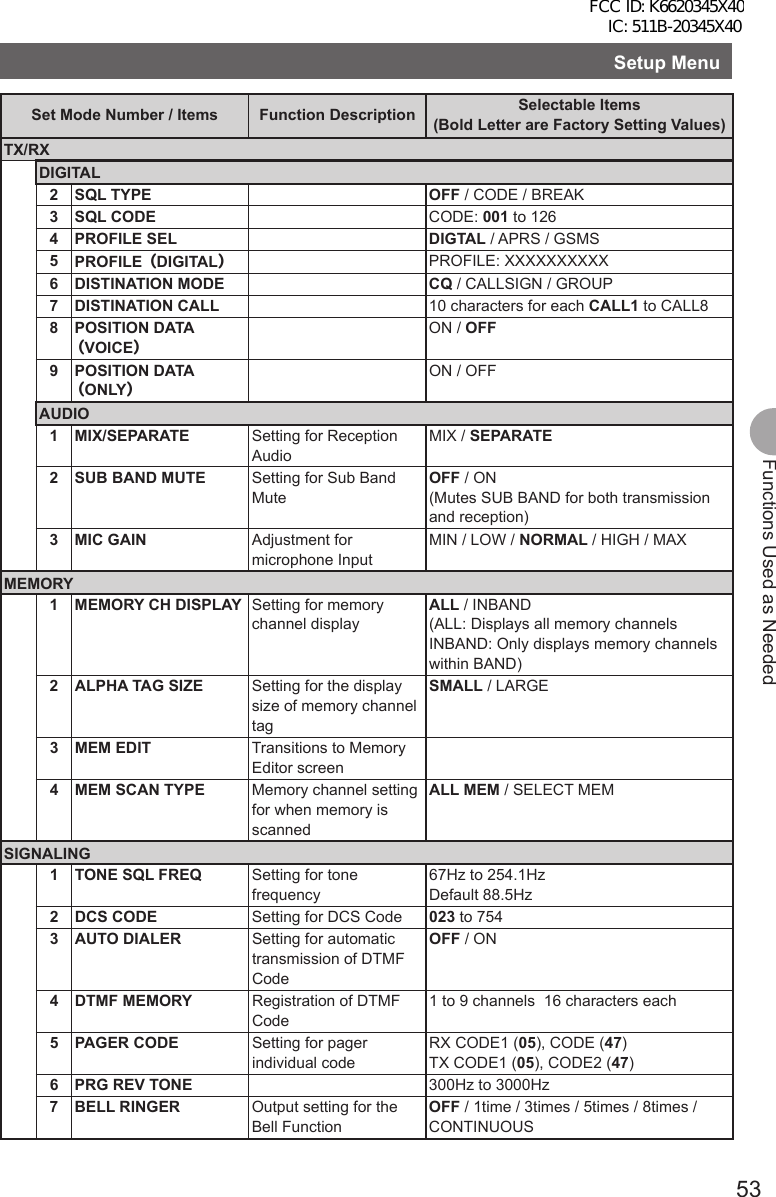
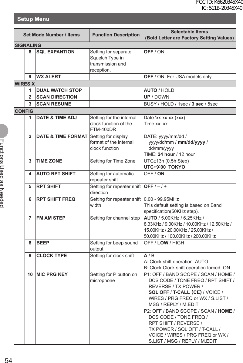
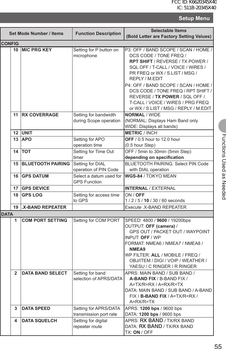
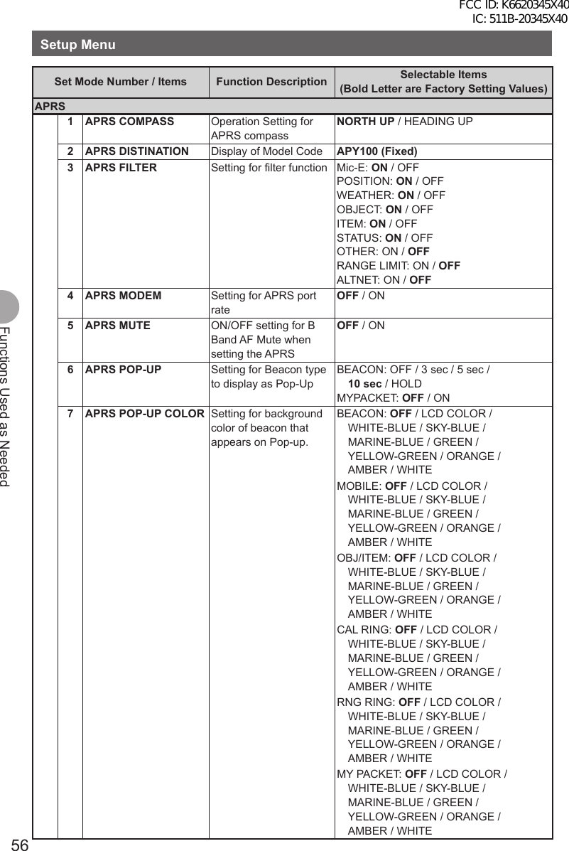
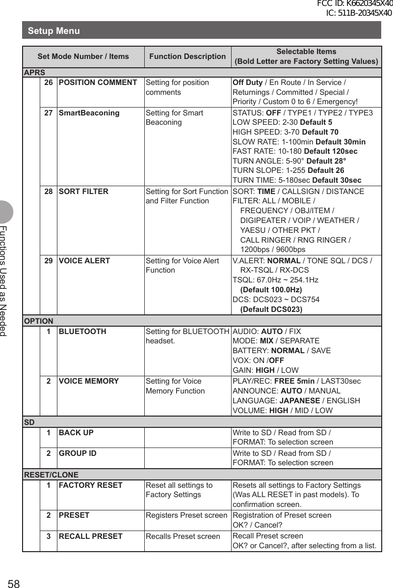
![52Functions Used as NeededFunctions Used as NeededSetup MenuSettings for the Setup MenuThe Setup Menu is a menu for selecting and setting various functions from a list for convenient use. ●Resetting the settings for the Setup MenuSettings for the Setup Menu can be reset to Factory Settings through the following operation:1 Press and hold M over 1 second. The Setup Menu appears.2 Tap [RESET/CLONE].3 Tap [1 FACTORY RESET].4 Tap [OK?]. Tapping [Cancel] cancels resetting.5 The FTM-400DR reboots. Setting content are reset and the FTM-400DR turns off once. Shortly afterwards, the FTM-400DR automatically restarts.Setup Menu Operations ListSet Mode Number / Items Function Description Selectable Items(Bold Letter are Factory Setting Values)DISPLAY1 DISPLAY SELECT Screen display setting for when M is pressed shortly.NAVIGATION: ON / OFFTIMER/CLOCK: ON / OFFALTITUDE: ON / OFFGPS INFORMATION: ON / OFF2 BACKGROUND COLORSetting for screen background color.GREEN / BLUE / ORANGE / PURPLE / GRAY3 BAND SCOPE Setting for screen display when SCOPE is executed.Setting for frequency bandwidthNARROW / WIDE4 LCD BRIGHTNESS Setting for LCD brightnessMIN / 2 / 3 / 4 / 5 / 6 / MAX5 LCD CONTRAST Setting for LCD contrast –3 / –2 / –1 / 0 / +1 / +2 / +36 TIME/VDD Setting for display content (Time/Voltage)TIME / VDDTX/RX1 MODE Reception mode switchingAUTO / FM / NARROW FM / AMDIGITAL1 DIGITAL MODE VOICE & DATA / FULL RATE (T.B.D.)FCC ID: K6620345X40 IC: 511B-20345X40](https://usermanual.wiki/Yaesu-Musen/20345X40.User-Manual/User-Guide-1854126-Page-53.png)
![57Functions Used as NeededSetup MenuSet Mode Number / Items Function Description Selectable Items(Bold Letter are Factory Setting Values)APRS8 APRS RINGER Setting for bell sound for when there is a incoming beacon.TX BEACON: ON / OFF RX BEACON: ON / OFF MY PACKET: ON / OFF CALL RINGER: ON / OFF RNG RINGER: 1-100 / OFF9 APRS RINGER (CALL) Call Sign setting for CALL RINGER1 to 8 stations10 APRS TXDELAY Setting for the data delivery delay time100ms / 150ms / 200ms / 250ms / 300ms / 400ms / 500ms / 750ms / 1000ms11 APRS UNITS Unit setting for APRS displayPOSITION: mm/ssDISTANCE: km / mileSPEED: km/h / knot / mphALTITUDE: m / ftBARO: hPa/mb/mmHg/inHgTEMP: ˚C / FRAIN: mm / inchWIND: m/s / mph / knot12 BEACON INF SELECT Setting for transmission beacon informationAMBIGUITY: OFF / 1-4digit SPD/CSE: ON / OFF ALTITUDE: ON / OFF13 BEACON STATUS TXT Input setting for Status TextSELECT: TEXT1-5 / OFFTX RATE: 1/1-1/8 1/2 (FREQ) - 1/8(FREQ), TEXT1-TEXT514 BEACON TX Switching between automatic and manual transmission of beaconAUTO: OFF / ON / SMARTINTERVAL: 30sec-60min Default 5minPROPORTIONAL: ON / OFFDECAY: ON / OFFLOW SPEED: 1-99 (5km/h or 3mph)RATE LIMIT: 5-180sec Default 30sec15 DIGI PATH SELECT Setting for digital repeater routeOFF / WIDE1-1 / WIDE1-1.WIDE2-1 / PATH1-PATH4 / FULL1 / FULL216 DIGI PATH 1 Address setting for digital repeater routeADDR1: ADDR2: No Input17 DIGI PATH 2 ADDR1: ADDR2: No Input18 DIGI PATH 3 ADDR1: ADDR2: No Input19 DIGI PATH 4 ADDR1: ADDR2: No Input20 DIGI PATH FULL 1 ADDR1: -ADDR8: No Input21 DIGI PATH FULL 2 ADDR1: -ADDR8: No Input22 PROFILE xxxxxx-xx23 MY POSITION SET Position setting of your stationGPS / MANUAL / POINT MEM GR1-1to GR4-424 MY POSITION Manual position setting of your stationLatitude: x xx°xx' xx"Longitude: x xxx°xx' xx"25 MY SYMBOL Setting for the symbol of your stationICON1:[/>] Car / ICON2: [/R] REC.Vehicle / ICON3: [/-] House QTH (VHF) / USER: [YY] Yaesu RadiosFCC ID: K6620345X40 IC: 511B-20345X40](https://usermanual.wiki/Yaesu-Musen/20345X40.User-Manual/User-Guide-1854126-Page-58.png)
![59Functions Used as NeededSetup MenuSet Mode Number / Items Function Description Selectable Items(Bold Letter are Factory Setting Values)RESET/CLONE4 MEM CH RESET Erases memory channelsALL MEM CH CLEAR: Only erases memory channels and keeps MENU content. To confirmation screen.5 MEM CH SORT Sorts memory channels. Sort A/B band memory channels. To confirmation screen.6 APRS RESET Resets APRS settings. Reset APRS settings. To confirmation screen.7 CLONE Copies the setting content of your radio to other.This radio → other (TX) /This radio ← other (RX) To selection screenApply settings to contents displayed on screen.Setting content displayed on screen when M is pressed shortly.1 Press and hold M over 1 second. The Setup Menu appears.2 Tap [DISPLAY].3 Tap [1 DISPLAY SELECT]. The display settings for the screen appears.4 Tap an item to display. Select the screen to display from [NAVIGATION] [TIMER/CLOCK] [ALTITUDE] [GPS INFOR]. Tapping an item switches between [ON] and [OFF].5 Set other screens. Repeat Step 4 to set other screens.6 Press and hold M over 1 second. The displayed screen is set and the screen returns to the previous one. Reference • Factory Settings: All screens are set to [OFF].FCC ID: K6620345X40 IC: 511B-20345X40](https://usermanual.wiki/Yaesu-Musen/20345X40.User-Manual/User-Guide-1854126-Page-60.png)
![60Functions Used as NeededSetup MenuSetting the Background Color of the ScreenThe background color for the screen can be selected from the following 5 colors:• Green • Blue • Orange • Purple • Grey1 Press and hold M over 1 second. The Setup Menu appears.2 Tap [DISPLAY].3 Tap [2 BACKGROUND COLOR] and select a background color. The background color changes in the following order each time [2 BACKGROUND COLOR] is tapped. [GREEN] → [BLUE] → [ORANGE] → [PURPLE] → [GRAY]4 Press and hold M over 1 second. The background color is set and the screen returns to the previous one. Reference • Factory Settings: All screens are set to [GREEN].Setting the Frequency Width for Band ScopeThe frequency band width to be displayed when Band Scope is operated can be set.1 Press and hold M over 1 second. The Setup Menu appears.2 Tap [DISPLAY].3 Tap [3 BAND SCOPE] and select frequency band width. Frequency band width switches between [NARROW] and [WIDE] each time [3 BAND SCOPE] is tapped. NARROW: Frequency band width appears in a narrow search width. WIDE: Frequency band width appears in a wide search width.4 Press and hold M over 1 second. The frequency band width is set and the screen returns to the previous one. Reference • Factory Setting: [NARROW]FCC ID: K6620345X40 IC: 511B-20345X40](https://usermanual.wiki/Yaesu-Musen/20345X40.User-Manual/User-Guide-1854126-Page-61.png)
![61Functions Used as NeededSetup MenuAdjusting the LCD Backlight Brightness LevelThe brightness level of the LCD backlight can be adjusted.1 Press and hold M over 1 second. The Setup Menu appears.2 Tap [DISPLAY].3 Tap [4 LCD BRICHTNESS]. The LCD Brightness Setting screen appears.4 Tap [–] or [+] to adjust brightness. Select the brightness from [MIN], [2], [3], [4], [5], [6], and [MAX]. The selected brightness can be confirmed on screen.5 Press and hold M over 1 second. The LCD Brightness is set and the screen returns to the previous one. Reference • Factory Setting: [MAX]Adjusting LCD ContrastThe contrast level of the screen can be adjusted.1 Press and hold M over 1 second. The Setup Menu appears.2 Tap [DISPLAY].3 Tap [5 LCD CONTRAST]. The LCD Contrast Setting screen appears.4 Tap [–] or [+] to adjust contrast. Select the contrast from [–3], [–2], [–1], [0], [+1], [+2], and [+3]. The selected contrast can be confirmed on screen.5 Press and hold M over 1 second. The LCD contrast level is set the screen returns to the previous one. Reference • Factory Setting: [0]FCC ID: K6620345X40 IC: 511B-20345X40](https://usermanual.wiki/Yaesu-Musen/20345X40.User-Manual/User-Guide-1854126-Page-62.png)
![62Functions Used as NeededSetup MenuSwitching between Time and Voltage displayThe display on the top right of the screen can be switched between [Time Display] and [Voltage Display].1 Press and hold M over 1 second. The Setup Menu appears.2 Tap [DISPLAY].3 Tap [6 TIME/VDD] and select the display content. The display switchws between [TIME] and [VDD] every time [6 TIME/VDD]. TIME: The Time appears. VDD: The voltage appears.4 Press and hold M over 1 second. The display content is set and the screen returns to the precious one. Reference • Factory Setting: [TIME]Adjusting volume respectively to A/B Bands.The volume for A Band and B Band can be separately adjusted. Additionally, if your radio is connected to external speakers, the A/B Band Audio can be separated to left and right speakers.1 Press and hold M over 1 second. The Setup Menu appears.2 Tap [TX/RX].3 Tap [AUDIO].4 Tap [1 MIX/ SEPERATE] and select ½½½. Audio is switched between [MIX] and [SEPERATE] each time [1 MIX/SEPERATE] is tapped. MIX: Simultaneously adjust volume for A Band and B Band. SEPERATE: Separately adjust volume for A Band and B Band.5 Press and hold M over 1 second. The selected volume adjustment is set and the screen returns to the previous one. Reference • Factory Setting: [MIX]FCC ID: K6620345X40 IC: 511B-20345X40](https://usermanual.wiki/Yaesu-Musen/20345X40.User-Manual/User-Guide-1854126-Page-63.png)
![63Functions Used as NeededSetup MenuSetting the Display Method for Memory ChannelsThe display method for registered memory channels can be selected from the following 2 methods:• ALL: Displays all registered memory channels• INBAND: Only displays memory channels within the band currently in use.1 Press and hold M over 1 second. The Setup Menu appears.2 Tap [MEMORY].3 Tap [1 MEMORY CH DISPLAY] and set the memory channels to display. Tapping [1 MEMORY CH DISPLAY] will switch between [ALL] and [INBAND].4 Press and hold M over 1 second. The display method for memory channels is set and the screen returns to the previous one. Reference • Factory Setting: [ALL]Setting the Squelch Type for transmissionPreset squelch types can be used separately for transmission and reception.1 Press and hold M over 1 second. The Setup Menu appears.2 Tap [SIGNALING].3 Tap [8 SQL EXPANSION] and select between OFF/ON. Tapping [8 SQL EXPANSION] switches between [ON] and [OFF]. OFF: Use the same squelch type for transmission and reception. ON: Use separate squelch type for transmission and reception.4 Press and hold M over 1 second. The squelch type for transmission and reception is set and the screen returns to the previous one. Reference • Factory Setting: [OFF]FCC ID: K6620345X40 IC: 511B-20345X40](https://usermanual.wiki/Yaesu-Musen/20345X40.User-Manual/User-Guide-1854126-Page-64.png)
![64Functions Used as NeededSetup MenuSetting the display format for the Clock FunctionThe display format for the internal clock can be chosen from the following types: • Date Display: Month/Day/Year, Year/Month/Day, Day/Month/Year, Year/Day/Month • Time Display: 24 Hour Display, 12 Hour Display1 Press and hold M over 1 second. The Setup Menu appears.2 Tap [CONFIG].3 Tap [2 DATA & TIME FORMAT]. The setting screen for date and time display appears.4 Tap [DATE]. The setting screen for date display format appears.5 Tap format to be displayed. Select the display format for the Date. mmm/dd/yyyy: Date appears as Month/Day/Year yyy/mmm/dd: Date appears as Year/Month/Day dd/mmm/yyyy: Date appears as Day/Month/Year yyy/dd/mmm: Date appears as Year/Day/Month6 Tap [BACK].7 Tap [TIME] and select the display format for time. Tapping [TIME] switches between [24 hour] and [12 hour].8 Press and hold M over 1 second. The Time and Date display format is set and the screen returns to the previous one. Reference • Factory Setting: Date Display Format mm/dd/yyyy, Date Display Format 24 hourFCC ID: K6620345X40 IC: 511B-20345X40](https://usermanual.wiki/Yaesu-Musen/20345X40.User-Manual/User-Guide-1854126-Page-65.png)
![65Functions Used as NeededSetup MenuSetting the Time ZoneThe internal clock can be set to time data from GPS (Coordinated Universal Time). On Factory Settings the internal clock is set to Japan Time (UTC+9:00 TOKYO) and does not need to be adjusted.The time zone can be adjusted in 0.5 hour units for up to ±13 hours.1 Press and hold M over 1 second. The Setup Menu appears.2 Tap [CONFIG].3 Tap [3 TIME ZONE]. The time zone appears in orange.4 Turn the O to adjust the time zone. Rotate the O and select the desired time zone for a oversea city. The time zone can be adjusted in 0.5 hour units for up to ±13 hours.5 Press O shortly. The time zone is set and displayed in green.6 Press and hold M over 1 second. Returns to the previous screen. Reference • Factory Setting: UTC+9:00 TOKYOSetting the Automatic Repeater ShiftWhen using the repeater for communication, the automatic repeater shift function that automatically starts communication via the repeater can be set to ON/OFF.1 Press and hold M over 1 second. The Setup Menu appears.2 Tap [CONFIG].3 Tap [4 AUTO RPT SHIFT] and select between ON/OFF. Tapping [4 AUTO RPT SHIFT] switches between [ON] and [OFF]. ON: Automatically starts communication using repeater shift. OFF: Manually select tone frequency and start communication4 Press and hold M over 1 second. The automatic repeater shift is set and the screen returns to the previous one. Reference • Factory Setting: ON FCC ID: K6620345X40 IC: 511B-20345X40](https://usermanual.wiki/Yaesu-Musen/20345X40.User-Manual/User-Guide-1854126-Page-66.png)
![66Functions Used as NeededSetup MenuSetting the Clock Shift of the MicrocomputerYou can set microcomputer clock signal so as not to receive as internal spurious by high frequency. Select [A] for normal time usage.1 Press and hold M over 1 second. The Setup Menu appears.2 Tap [CONFIG].3 Tap [9 CLOCK TYPE] and set A/B. Tapping [9 CLOCK TYPE] switches between [A] and [B].A: The clock shift function automatically switches between ON and OFF.B: The clock shift function is active at all times.4 Press and hold M over 1 second. The clock type is set and the screen returns to the previous one. Reference • Factory Setting: ASetting the Program Keys on the MicrophoneAssign functions to the program keys (P1 to P4) on the accessory microphone (MH-48).1 Press and hold M over 1 second. The Setup Menu appears.2 Tap [CONFIG].3 Tap [10 MIC PRG KEY]. The Microphone Program Keys setting screen appears.4 Tap the Program key you would like to set. Tap the Program Key (P1 to P4) you would like to assign a function. The functions that can be assigned are displayed. If the function you would like to assign is not displayed, scroll the screen with [▲] and [▼].5 Tap the function you would like to assign. The function to assign to the program key is selected.6 Tap [BACK]. The screen returns to the program key (P1 to P4) selection.7 Set functions for the other program keys. Repeat steps 4 to 6 and assign functions to other function keys.8 Press and hold M over 1 second. The function is assigned to the program key and returns to the previous screen. Reference • Factory Setting: P1: SQL OFF P2: HOME P3: RPT SHIFT P4: TX POWERFCC ID: K6620345X40 IC: 511B-20345X40](https://usermanual.wiki/Yaesu-Musen/20345X40.User-Manual/User-Guide-1854126-Page-67.png)
![67Functions Used as NeededSetup MenuSetting the Bandwidth to ScopeThe Bandwidth for when scoping in VFO mode or Memory mode can be set.1 Press and hold M over 1 second. The Setup Menu appears.2 Tap [CONFIG].3 Tap [11 RX COVERAGE] to select NORMAL/WIDE. Tapping [11 RX COVERAGE] switches between [NORMAL] and [WIDE]. NORMAL: Scopes Ham Band only. WIDE: Scopes all Bands.4 Press and hold M over 1 second. The bandwidth to scope is set and the screen returns to the previous one. Reference • Factory Setting: NORMALSetting the unit of measurement to be displayedThe unit of measurement can be set for displaying altitude, distance, and speed.1 Press and hold M over 1 second. The Setup Menu appears.2 Tap [CONFIG].3 Tap [12 UNIT] and select METRIC/INCH. Tapping [12 UNIT] switches between [METRIC] and [INCH]. METRIC: The unit of measurement appears in metric. INCH: The unit of measurement appears in inch.4 Press and hold M over 1 second. The unit of measurement is set and the screen returns to the previous one. Reference • Factory Setting: METRIC FCC ID: K6620345X40 IC: 511B-20345X40](https://usermanual.wiki/Yaesu-Musen/20345X40.User-Manual/User-Guide-1854126-Page-68.png)
![68Functions Used as NeededSetup MenuAutomatically Turning Off the Power APO FunctionThe FTM-400DR can be set so that it turns off automatically if you do not operate it for a certain period of time. You can change the time until the FTM-400DR is turned off automatically Use this function after setting the clock, referring to [Setting the Clock (See page 21)].1 Press and hold M over 1 second. The Setup Menu appears.2 Tap [CONFIG].3 Tap [13 APO]. The APO setting screen appears.4 Tap [–] or [+] to adjust the time. Specify the time until the FTM-400DR is turned off automatically in steps of 30 minutes. OFF / 30 min / 1 hour to 12 hours5 Press and hold M over 1 second. The Auto Power Off function is set and the screen returns to the previous one. Reference • Factory Setting: OFFRestricting the Continuous Transmission Time TOT FunctionThe FTM-400DR can be set that it automatically returns to reception state after performing continuous transmission for a certain period of time. Accidental transmission of unnecessary radio waves and unwanted battery power consumption can be prevented (time-out timer function).1 Press and hold M over 1 second. The Setup Menu appears.2 Tap [CONFIG].3 Tap [14 TOT]. The time display for TOT appears in orange.4 Turn the O to set the time. Turn the O to set the Time Out time in steps of 5 minutes. OFF / 5 min to 30 min5 Press O shortly. The time is set and displayed in green.6 Press and hold M over 1 second. Returns to the previous screen. Reference • Factory Setting: 5 minFCC ID: K6620345X40 IC: 511B-20345X40](https://usermanual.wiki/Yaesu-Musen/20345X40.User-Manual/User-Guide-1854126-Page-69.png)
![69Functions Used as NeededSetup MenuSetting PIN Code for a BLUETOOTH headsetUsing a BLUETOOTH headset requires setting its PIN code to the FTM-400DR.Reference• The PIN code for a BLUETOOTH headset from our company is 6111. If the BLUETOOTH headset is not from our company, check the PIN code by refereeing to the instruction manual for that product.1 Press and hold M over 1 second. The Setup Menu appears.2 Tap [CONFIG].3 Tap [15 BLUETOOTH PAIRING]. PIN code input screen appears4 Tap the numeric keys to input the PIN code. By tapping the numbers displayed on screen, input the 4 digit code. Reference • Tap [Cancel] if incorrect number is entered.5 Tap [ENT]. The PIN code is set.6 Press and hold M over 1 second. Returns to the previous screen. Reference • Factory Setting: 6111Selecting Datum for GPS function.Select a datum used for the GPS function.1 Press and hold M over 1 second. The Setup Menu appears.2 Tap [CONFIG].3 Tap [16 GPS DATUM] to set a datum. Tapping [16 GPS DATUM] switches between [TOKYO MEAN] and [WGS 84].WGS-84: The standard setting for worldwide standard. Select WGS-84 under normal operation.TOKYO MEAN: Enables reducing the error in positioning when using GPS in Japan (Tokyo)4 Press and hold M over 1 second. The datum for GPS is set and the screen returns to the previous one.FCC ID: K6620345X40 IC: 511B-20345X40](https://usermanual.wiki/Yaesu-Musen/20345X40.User-Manual/User-Guide-1854126-Page-70.png)
![70Functions Used as NeededSetup MenuSetting the GPS Device to UseBefore using the GPS function, select whether to use the internal GPS function of the FTM-400DR or a connected external GPS device.1 Press and hold M over 1 second. The Setup Menu appears.2 Tap [CONFIG].3 Tap [17 GPS DEVICE] and set the GPS device. Tapping [17 GPS DEVICE] switches between [INTERNAL] and [EXTERNAL]. INTERNAL: Use the internal GPS function of the FTM-400DR. EXTERNAL: Use the connected external GPS device.4 Press and hold M over 1 second. The GPS function (or device) is set and the screen returns to the previous one. Reference • Factory Setting: INTERNALSetting Time for Accessing GPSThe time for accessing GPS for receiving signals and information can be set.1 Press and hold M over 1 second. The Setup Menu appears.2 Tap [CONFIG].3 Tap [18 GPS LOG]. The GPS LOG Time Setting screen appears.4 Tap [–] or [+] to set the time. Set the time that the FTM-400DR accesses GPS. The FTM-400DR does not access GPS if [OFF] is tapped. OFF/1 sec/2 sec/5 sec/10 sec/30 sec/60 sec5 Press and hold M over 1 second. The access time to GPS is set and the screen returns to the previous one. Reference • Factory Setting: 10 sec (when GPS antenna connected) OFF (when GPS antenna unconnected)FCC ID: K6620345X40 IC: 511B-20345X40](https://usermanual.wiki/Yaesu-Musen/20345X40.User-Manual/User-Guide-1854126-Page-71.png)
![71Functions Used as NeededSetup MenuCommunicating by crossing A Band and B band frequenciesAudio can be transmitted with B Band (430MHz band) while receiving it with A Band (144MHz band). Similarly, audio can be transmitted with A Band while receiving it with B Band.1 Press and hold M over 1 second. The Setup Menu appears.2 Tap [CONFIG].3 Tap [19 X-BAND REPEATER]. The X-BAND REPEATER confirmation screen appears.4 Tap [OK?]. X-BAND REPEATER is activated. To deactivate it, tap [Cancel].5 Press and hold M over 1 second. Returns to the previous screen. Reference • Factory Setting: OFFSetting USB Camera to Use.The FTM-400DR can capture images and video by connecting a USB camera and transmit/ receive them. You can set the picture size and quality for the USB camera you are going to use.1 Press and hold M over 1 second. The Setup Menu appears.2 Tap [OPTION].3 Tap [1 USB CAMERA]. The USB CAMERA setting screen appears. •PICTURE SIZE: Set the picture size you will capture. •PICTURE QUALITY: Set the image quality you will capture.4 Tap [PICTURE SIZE] to set the picture size. Tapping [PICTURE SIZE] switches between [160 × 1120] and [320 × 240].5 Tap [PICTURE QUALITY] to set the picture quality. Tapping [PICTURE QUALITY] switches between [NORMAL] and [HIGH].6 Press and hold M over 1 second. The picture settings for the USB Camera are set and the screen returns to the previous one.FCC ID: K6620345X40 IC: 511B-20345X40](https://usermanual.wiki/Yaesu-Musen/20345X40.User-Manual/User-Guide-1854126-Page-72.png)
![72Functions Used as NeededSetup MenuSetting operations of BLUETOOTH Headset to UseYou can set operations of the BLUETOOTH headset connected to the FTM-400DR.Setting content are as follows: • AUDIO: Set the audio output operation of the BLUETOOTH headset. • BATTERY: Set the battery of the BLUETOOTH headset. • VOX: Set the switching operation of the BLUETOOTH headset. • GAIN: Set the VOX sensitivity of the BLUETOOTH headset.1 Press and hold M over 1 second. The Setup Menu appears.2 Tap [OPTION].3 Tap [2 BLUETOOTH]. The BLUETOOTH Setting screen appears.4 Tap [AUDIO] to set the audio output operation of the headset. Tapping [AUDIO] switches between [AUTO] and [FIX]. •AUTO: When the BLUETOOTH headset is connected, the audio is only heard through the headset. •FIX: When the BLUETOOTH headset is connected, the audio is heard from both speakers and headset.5 Tap [BATTERY] to set the battery usage condition of the headset. Tapping [BATTERY] switches between [NORMAL] and [SAVE]. •NORMAL: The battery save function for the BLUETOOTH headset is set to OFF. •SAVE: The battery save function for the BLUETOOTH headset is set to ON.6 Tap [VOX] to enable or disable the transmission and reception switching on the headset. Tapping [VOX] switches between [OFF] and [ON]. •OFF: Transmission and reception cannot be switched on the BLUETOOTH headset. •ON: Transmission and reception can be switched on the BLUETOOTH headset. Reference • Selecting [ON] displays the option for selecting [GAIN].7 Tap [GAIN] to set the VOX sensitivity. Tapping [GAIN] switches between [HIGH] and [LOW]. •HIGT: The VOX sensitivity for the BLUETOOTH headset is set to high. •LOW: The VOX sensitivity for the BLUETOOTH headset is set to low.FCC ID: K6620345X40 IC: 511B-20345X40](https://usermanual.wiki/Yaesu-Musen/20345X40.User-Manual/User-Guide-1854126-Page-73.png)
![73Functions Used as NeededSetup Menu8 Press and hold M over 1 second. The BLUETOOTH is set and the screenreturns to the previous one. Reference • Factory Setting: AUDIO: AUTO BATTERY: NORMAL VOX: OFF GAIN: HIGHSetting Operations of the Voice Announcement FunctionYou can set the operations of the Voice Announcement function equipped to the FTM-400DR.Setting content are as follows: • PLAY/REC: Set conditions for Record/Play. • ANNOUNCE: Set conditions for the Voice Announcement of frequency. • LANGUAGE: Set the language to use for the Voice Announcement. • VOLUME: Set the volume of the Voice Announcement.1 Press and hold M over 1 second. The Setup Menu appears.2 Tap [OPTION].3 Tap [3 VOICE MEMORY]. The VOICE MEMORY setting screen appears.4 Tap [PLAY/REC] to set the Record/Play time. Tapping [PLAY/REC] switches between [FREE5min] and [LAST30sec]. •FREE5min: With 8 recording areas, the total of 5 minutes can be recorded. •LAST30sec: Records the last 30 seconds before [■ STOP] is pressed.5 Tap [ANNOUNCE] to set the Voice Announcement of frequency. Tapping [ANNOUNCE] switches between [AUTO], [OFF], and [MANUAL]. •AUTO: The frequency is announced by voice when [VOICE] is tapped or Band is changed. •OFF: The frequency is not announced by voice. •MANUAL: The frequency is announced by voice when [VOICE] is tapped.FCC ID: K6620345X40 IC: 511B-20345X40](https://usermanual.wiki/Yaesu-Musen/20345X40.User-Manual/User-Guide-1854126-Page-74.png)
![74Functions Used as NeededSetup Menu6 Tap [LANGUAGE] to set the language for the Voice Announcement. Tapping [LANGUAGE] switches between [JAPANESE] and [ENGLISH]. •JAPANESE: Announces the frequency in Japanese. •ENGLISH: Announces the frequency in English.7 Tap [VOLUME] to set the volume of Voice Announcement. Tapping [VOLUME] switches among [HIGH], [MID], and [LOW]. •HIGH: The volume of Voice Announcement is set to [HIGH]. •MID: The volume of Voice Announcement is set to [MEDIUM]. •HIGH: The volume of Voice Announcement is set to [LOW].8 Press and hold M over 1 second. The settings for the Voice Announcement Function are set and the screen returns to the previous one. Reference • Factory Setting: PLAY/REC: FREE 5 min ANNOUNCE: AUTO LANGUAGE: JAPANESE VOLUME: HIGHWriting Group ID to microSD Memory CardGroup ID information registered to the FTM-400DR can be written to microSD memory card.Additionally, Group ID information saved to the microSD memory card can be read to the internal memory of the FTM-400DR.1 Press and hold M over 1 second. The Setup Menu appears.2 Tap [SD].3 Tap [2 GROUP ID]. The GROUP ID Selection screen appears.4 Tap an item to select. Tap each item to select. •Write to SD: Write group ID information registered to the FTM-400DR to microSD memory card. •Read to SD: Read and register Group IDs saved to the microSD memory card to FTM-400DR. •FORMAT: Format the microSD memory card.5 Tap [OK?]. The selected items are activated. To cancel the operation, tap [Cancel].6 Press and hold M over 1 second. Returns to the previous screen. Reference • Factory Setting: FORMATFCC ID: K6620345X40 IC: 511B-20345X40](https://usermanual.wiki/Yaesu-Musen/20345X40.User-Manual/User-Guide-1854126-Page-75.png)
![75Functions Used as NeededSetup MenuRegistering PresetOnly one current setting, such as frequency or memory channel can be registered to Preset.1 Press and hold M over 1 second. The Setup Menu appears.2 Tap [RESET/CLONE].3 Tap [2 PRESET]. The Preset registration confirmation screen appears.4 Tap [OK?]. The PRESET screen is registered. To cancel the registration, tap [Cancel].5 Press and hold M over 1 second. Returns to the previous screen.Recalling the Registered Preset.The registered Preset screen can be recalled from the Setup Menu.1 Press and hold M over 1 second. The Setup Menu appears.2 Tap [RESET/CLONE].3 Tap [3 RECALL PRESET]. The list of registered Preset screens appears.4 Tap the Preset screen to recall. Tap the Preset screen to recall from the list of Preset screens. The screen registered to Preset appears on screen. To cancel recalling, tap [Cancel].FCC ID: K6620345X40 IC: 511B-20345X40](https://usermanual.wiki/Yaesu-Musen/20345X40.User-Manual/User-Guide-1854126-Page-76.png)
![76Functions Used as NeededSetup MenuDeleting Memory ChannelsYou can delete only registered memory channels. Information besides memory channel, such as menu content or setting items, cannot be deleted.Reference• To reset all settings and information to Factory Settings, tap [RESET/CLONE] and then [1 FACTORY RESET]. Doing so resets all registered information to default settings.1 Press and hold M over 1 second. The Setup Menu appears.2 Tap [RESET/CLONE].3 Tap [4 MEM CH RESET]. The memory channel deletion confirmation screen appears.4 Tap [OK?]. All memory channels are deleted. To cancel deletion, tap [Cancel].5 Press and hold M over 1 second. Returns to the previous screen.Sorting Registered Memory Channels in Order.You can sort the registered memory channels in order.1 Press and hold M over 1 second. The Setup Menu appears.2 Tap [RESET/CLONE].3 Tap [5 MEM CH SORT].4 Tap [OK?]. The memory channels are sorted in order of lowest frequency. To cancel sorting, tap [Cancel].5 The FTM-400DR restarts_. The FTM-400DR turns off once, then restarts automatically.FCC ID: K6620345X40 IC: 511B-20345X40](https://usermanual.wiki/Yaesu-Musen/20345X40.User-Manual/User-Guide-1854126-Page-77.png)
![77Functions Used as NeededSetup MenuDeleting Settings Configured for APRS Function.You can delete all information for settings configured for the APRS function.1 Press and hold M over 1 second. The Setup Menu appears.2 Tap [RESET/CLONE].3 Tap [6 APRS RESET]. The deletion confirmation screen appears.4 Tap [OK?]. Settings information for the APRS Function are deleted. To cancel deletion, tap [Cancel].5 Press and hold M over 1 second. Returns to the previous screen.The Clone Function For copying settings to another FTM-400DRInformation registered to this FTM-400DR can be copied to other FTM-400DR. Additionally, information registered to other FTM-400DR can be copied to this FTM-400DR.1 Turn off the FTM-400DR and connect the Clone Cable. Connect this FTM-400DR with another FTM-400DR with the Clone Cable.2 Press P. Turn on the power of both FTM-400DR.3 Press and hold M over 1 second.4 Tap [RESET/CLONE].5 Tap [7 CLONE].6 Tap [This radio → other (X)] for the sending FTM-400DR (copy source). Tap [This radio ← other (X)] for the receiving FTM-400DR (copy destination).7 Tap [OK?]. Copying (Cloning) starts. To cancel Cloning, tap [Cancel]. Once copying (Cloning) is complete, [COMPLETE] appears on screen.8 Turn off the power of FTM-400DR and disconnect the cable. FCC ID: K6620345X40 IC: 511B-20345X40](https://usermanual.wiki/Yaesu-Musen/20345X40.User-Manual/User-Guide-1854126-Page-78.png)
![78Functions Used as NeededSetup MenuReference• If [ERROR] appears while copying (Cloning), check the connection of the Clone cable and restart the operation from the beginning.• If copying (Cloning) is abnormally aborted due to power failure, the receiving FTM-400DR will be automatically reset all information. Check that there are no abnormalities with the power and restart operation from the beginning.FCC ID: K6620345X40 IC: 511B-20345X40](https://usermanual.wiki/Yaesu-Musen/20345X40.User-Manual/User-Guide-1854126-Page-79.png)