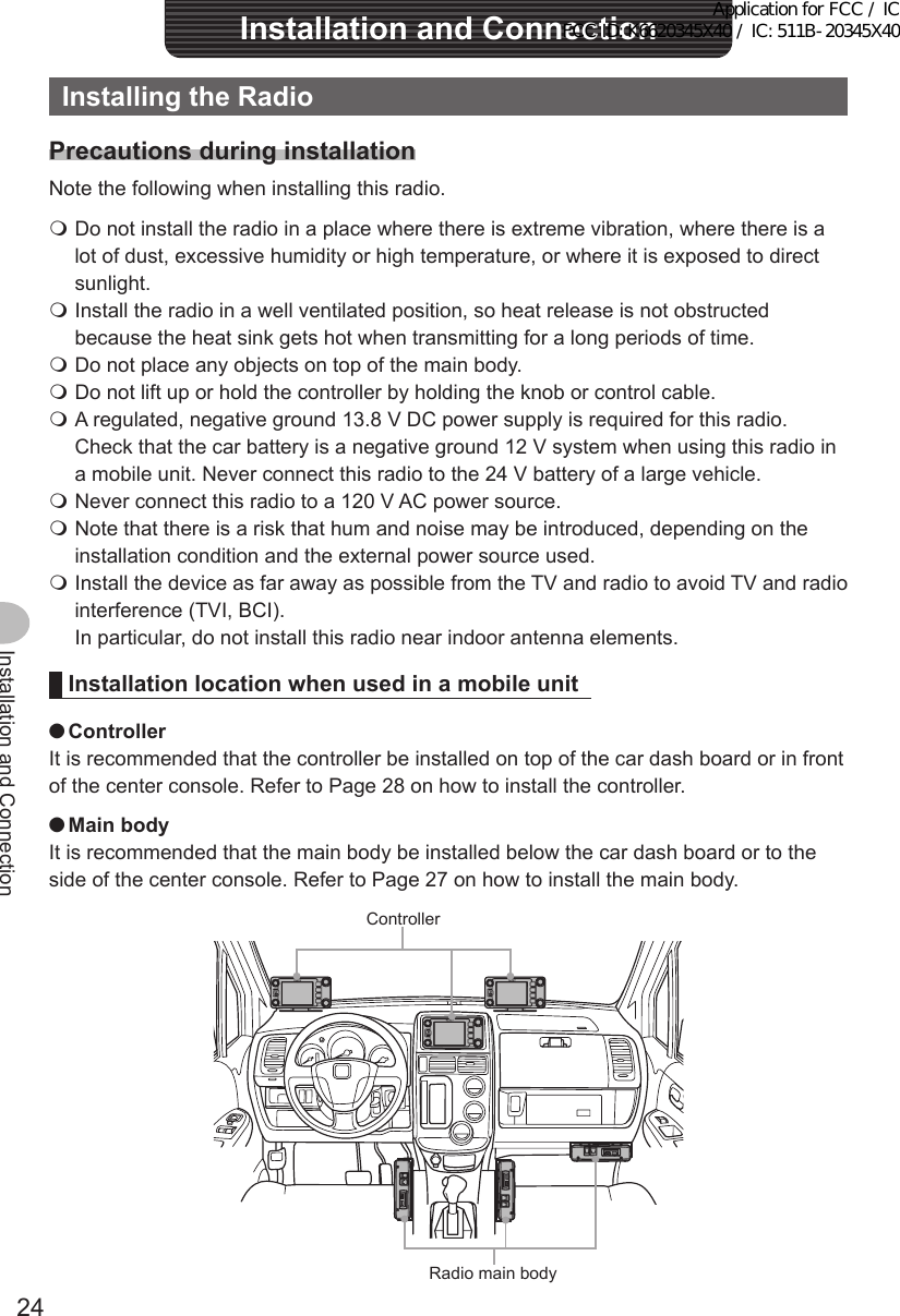
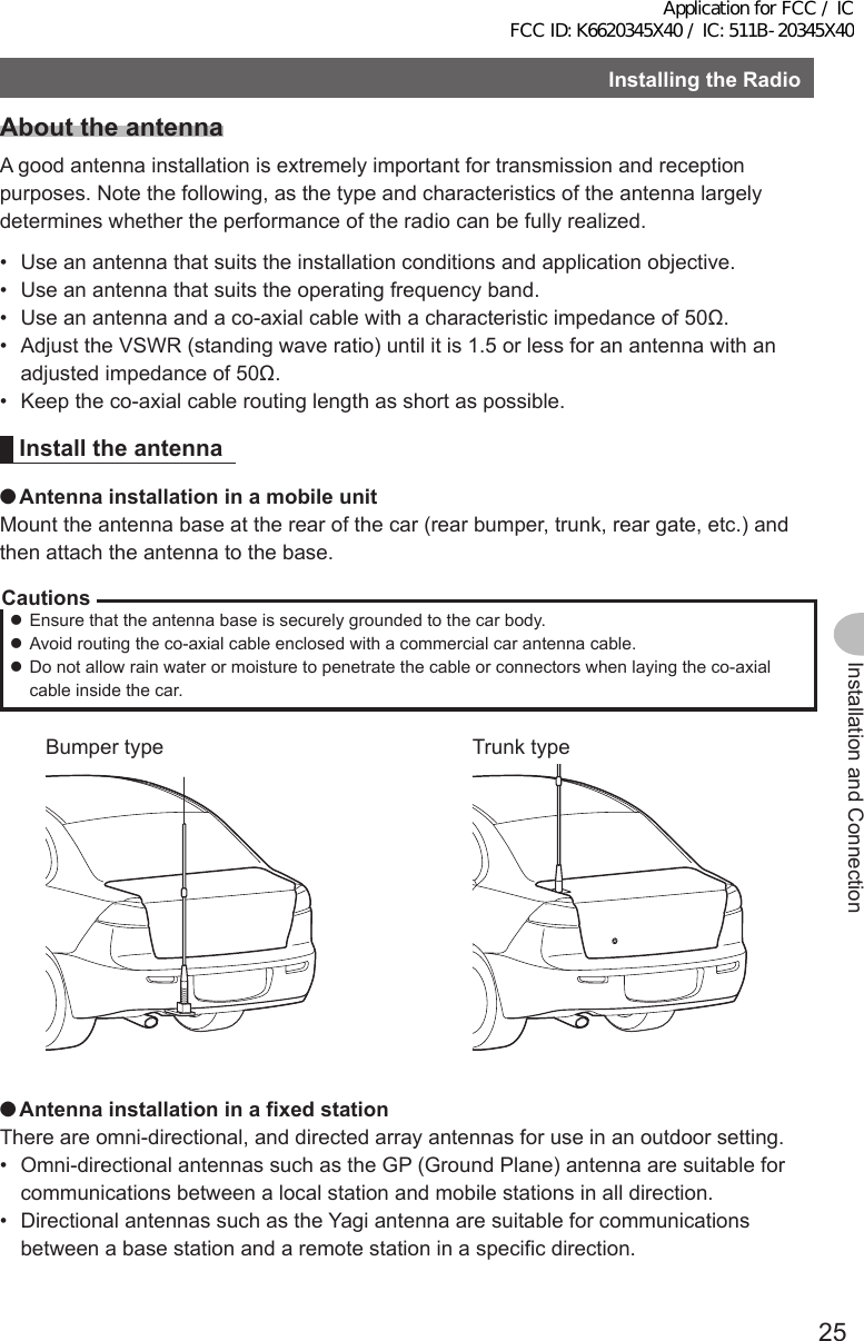
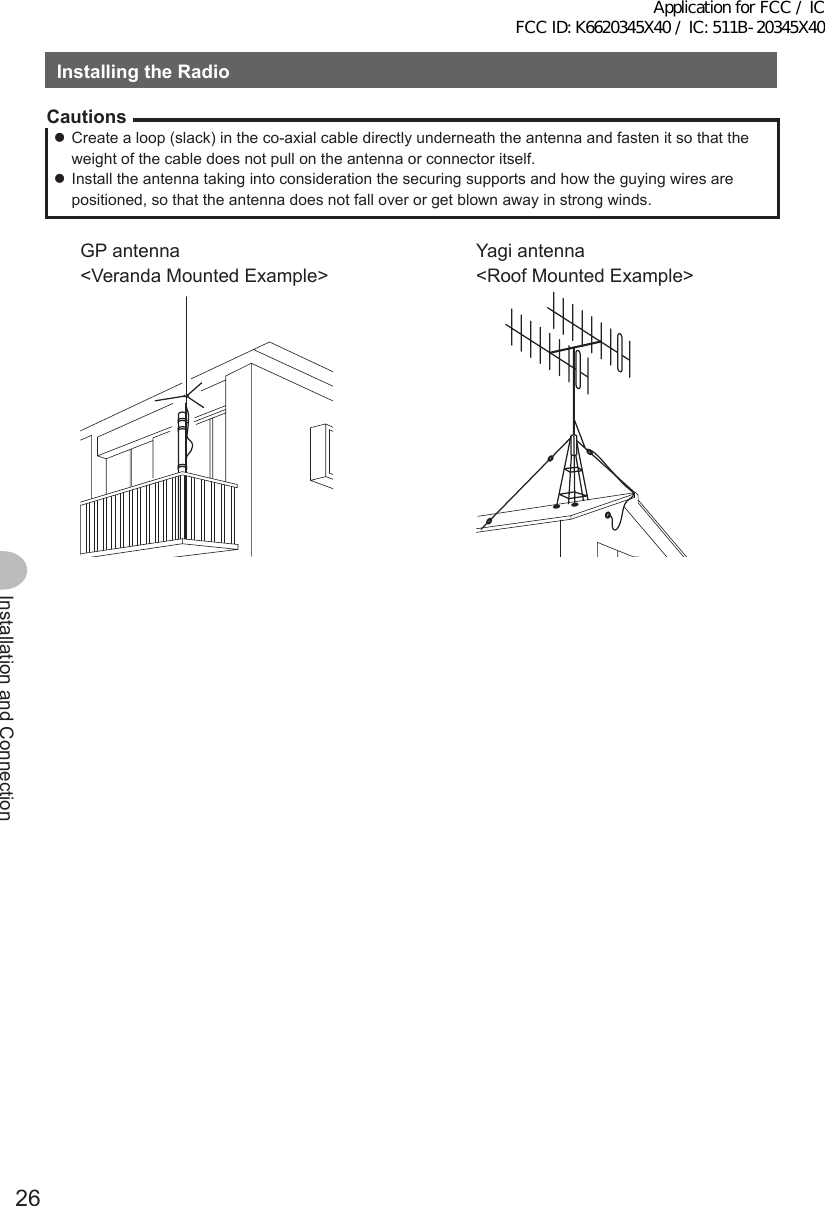
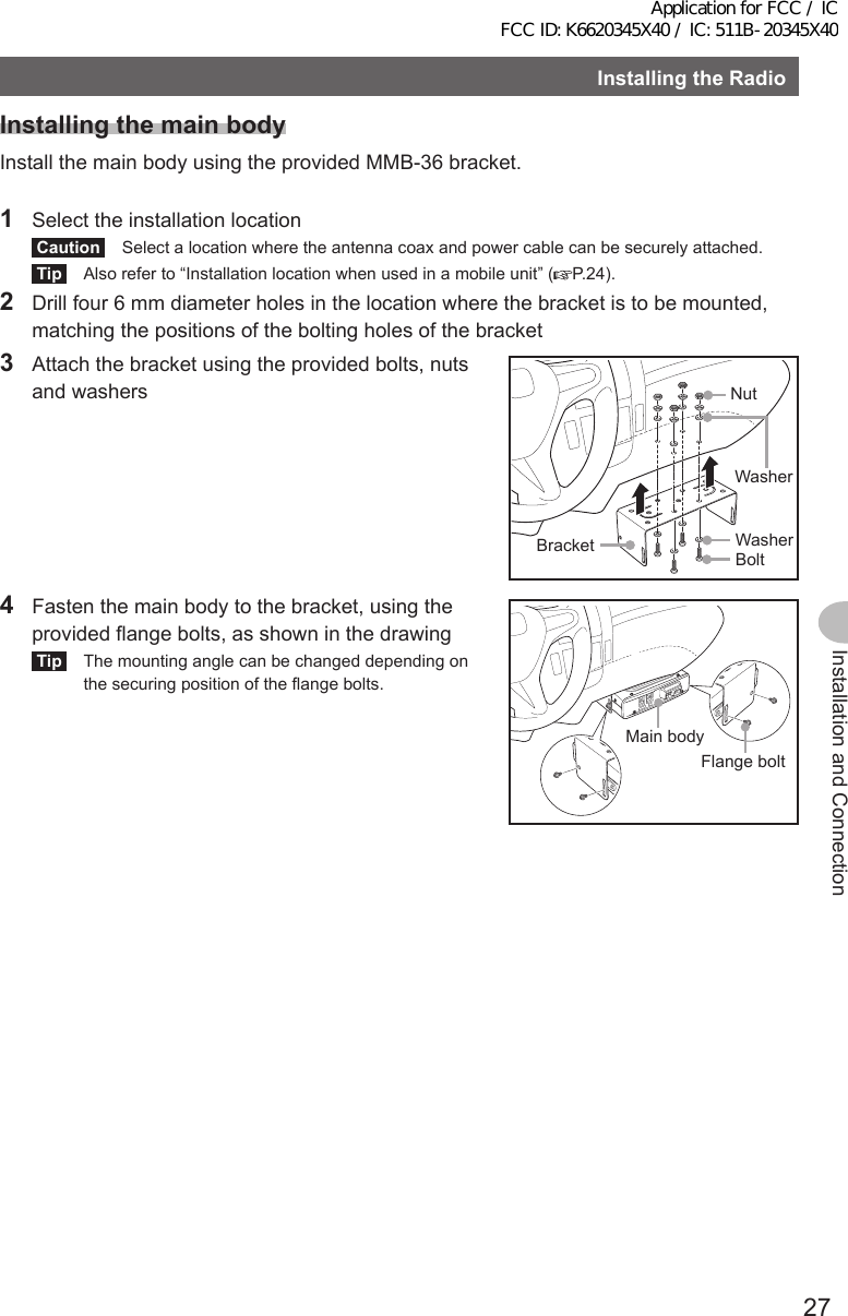
Yaesu Musen 20345X40 AMATEUR RADIO WITH SCANNING RECEIVER User Manual OM
Yaesu Musen Co., Ltd. AMATEUR RADIO WITH SCANNING RECEIVER OM
Contents
- 1. User Manual
- 2. User Manual 1
- 3. User Manual 2
- 4. User Manual 3
- 5. User Manual 4
- 6. User Manual 5
- 7. User Manual 6
- 8. User Manual 7
- 9. User Manual 8
- 10. User Manual 9
- 11. User Manual 10
- 12. User Manual 11
- 13. User Manual 12
- 14. User Manual 13
- 15. User Manual 14
- 16. User Manual 15
- 17. User Manual 16
- 18. User Manual 17
- 19. User Manual 18
- 20. User Manual 19
- 21. User Manual 20
- 22. User Manual 21
User Manual 2
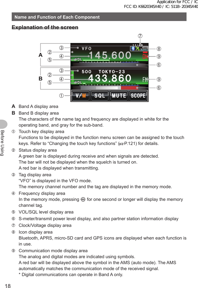
![19Before UsingNameandFunctionofEachComponent ●DualbandscreenBand A and Band B will be displayed at the top and bottom.ᲹᲽᲾᲸᲸ ᳀ᲾᲸ61-;1Ჺ/76'5%12'/8 53.8(1ᲽᲸᲸ[V/M] The VFO channel and memory channel will be switched by touching this symbol. The “V” is displayed in orange in the VFO mode while the “M” is displayed in orange in the memory mode.[SQL] The squelch level can be set after touching this symbol. The characters are displayed in orange for 5 seconds during the time that the squelch level can be set.[MUTE] The receive audio can be muted by touching this. The characters are displayed in orange when the sound has been muted.[SCOPE] The band scope operation toggles on or off each time this symbol is touched. The characters are displayed in orange during the band scope operation. ●BandscopescreenThe screen appears as shown, when the band scope is turned on.5%12'/76'ᲽᲿ᳁ᲹᲹᲹᲽᲾᲸᲸ8(1/853.Tip The width of the band scope can be set to either “WIDE” or “NARROW” under [DISPLAY]→[4BANDSCOPE] in the set-up menu. ●Function menu screenWhen is pressed, the function menu is displayed on the screen under the operating band.ᲹᲽᲾᲸᲸᲹᲺ᳀;1-1*#/#/76'5%12'/8 53.ᲹᲽᲾᲸᲸ8(15-+25'.1((&96Z294*+5%#0 4'8(9&$#%-[BACK][FWD] The menu changes each time these symbols are touched.Tip The functions displayed in the menu can be assigned to the touch keys at the bottom of the display. Refer to Page 121 for details.Application for FCC / IC FCC ID: K6620345X40 / IC: 511B-20345X40](https://usermanual.wiki/Yaesu-Musen/20345X40.User-Manual-2/User-Guide-2766129-Page-2.png)
![20Before UsingNameandFunctionofEachComponentChangethedisplaymodeThe display mode will switch in the sequence each time is pressed.Frequency display screen→Compass/Lat&Lon display screen→Altitude display screen*→Timer/Clock screen*→GPS screen** This screen will be displayed when [DISPLAY]→[1DISPLAYSELECT] is set to “ON” in the set-up menu. ●CompassscreenThe direction of travel of your own station and direction coordinate of the received station are displayed in the compass screen.%1/2#55Ჸ18( ᲹᲽᲸ᳁Ჸ&+56#0%'MO/;;4.Ჺ.Ჹ/'/14;09'5᳂,#<4.᳂ᲹCOMPASS Displays the compass settings. There are two settings, “Heading Up” where the direction of travel is on top, and “North Up” where North is always on top. Refer to “Change the Compass Settings” (P.94) for details.DISTANCE When a saved position information is recalled, the distance from the current position is displayed.[YR] When this symbol is touched, the position of the partner station that is received is displayed in the compass (when the position information is included in the signal), and the symbol is shown in orange.[MY] When this symbol is touched, the direction of travel of your own station is displayed in the compass, and this symbol is displayed in orange.[MEMORY] When this symbol is touched, the position information being displayed is saved in the memory.[] When this symbol is touched while the display is green, the position information saved in the memory under the tag “” is displayed. When this symbol is touched while the display is blinking, the position information displayed in the compass will be saved in the memory under the tag “”.[L1] When this symbol is touched while the display is green, the position information saved in the memory under the tag “L1” is displayed. When this symbol is touched while the display is blinking, the position information displayed in the compass will be saved in the memory under the tag “L1”.[L2] When this symbol is touched while the display is green, the position information saved in the memory under the tag “L2” is displayed. When this symbol is touched while the display is blinking, the position information displayed in the compass will be saved in the memory under the tag “L2”.Application for FCC / IC FCC ID: K6620345X40 / IC: 511B-20345X40](https://usermanual.wiki/Yaesu-Musen/20345X40.User-Manual-2/User-Guide-2766129-Page-3.png)
![21Before UsingNameandFunctionofEachComponent ●AltitudedisplayscreenThe altitude of the current location is shown in the bar graph display.Ჸ1ᲽᲸᲸ8( ᲹᲽᲸᲺᲽ᳀O#.6+67&'5%#.'%.'#4ALTITUDE Displays the current altitude.Verticalaxis Represents the altitude.Horizontalaxis Represents the distance.[SCALE] When this symbol is touched, the scale of the distance changes.[CLEAR] When this symbol is touched, the graph display will be cleared (erased). ●Timer/ClockscreenThe current time is shown in analog and digital formats. The date is also shown.Ჸ18(ᲹᲹᲽᲸᲸ᳁ᲸᲸ/1&'ᲺᲸᲺᲸᲹ#7) ᲽᲸᲸ [MODE] The mode switches between the lap timer mode and the countdown timer mode each time this symbol is touched.Application for FCC / IC FCC ID: K6620345X40 / IC: 511B-20345X40](https://usermanual.wiki/Yaesu-Musen/20345X40.User-Manual-2/User-Guide-2766129-Page-4.png)
![22Before UsingNameandFunctionofEachComponentᲸᲸᲸᲸ ᲸᲸᲸᲸ ᲺᲹ/1&'6+/'4.#25612Ჸ18(ᲹᲽᲸᲸᲽᲸᲸ ●Laptimerscreen[START] The count starts when this symbol is touched.[LAP] The lap time is then saved in the memory (a maximum of 99 lap times can be saved) and displayed in the upper lap display window when this symbol is touched. The lap time (of the new interval) being measured will be displayed in the lower lap display window.[STOP] The count stops when this symbol is touched.[RECALL] When this symbol is touched, the lap time saved in the memory is shown in the upper lap display window while the split time is shown below. When there are multiple lap times, touch [][] to move between the lap times. Touch [RECALL] again to return to the measurement screen.[RESET] The counter is reset when this symbol is touched.ᲽᲸᲹᲸᲸᲸᲸᲽᲸᲸᲺᲸ%1706& 1906+/'4/1&' 56#46 4'5'6Ჸ1ᲽᲸᲸ8( ᲹᲽᲸ ●Countdowntimerscreen[START] The count starts when this symbol is touched.[STOP] The count stops when this symbol is touched.[RESET] The counter is reset when this symbol is touched.[SETUP] The count time can be changed (from 1 minute to 99 hours and 59 minutes) when this symbol is touched. Each time this symbol is touched, the setting will switch from “Hours” to “Minutes” to “Confirm”. The time can be changed by touching [-] and [+] or turning .Application for FCC / IC FCC ID: K6620345X40 / IC: 511B-20345X40](https://usermanual.wiki/Yaesu-Musen/20345X40.User-Manual-2/User-Guide-2766129-Page-5.png)
![23Before UsingNameandFunctionofEachComponent ●GPSscreenThe GPS satellite statuses are shown with numbered icons.)25+0(1Ჸ1ᲽᲸᲸ8( ᲹᲽᲸ1,2,etc. Received satellite number Signal strength High Signal strength Medium Signal strength LowInput the characterThe keyboard screen is displayed when entering a memory channel tag or the call sign of your own station. ●NumbersandsymbolsinputscreenᲹᲺ Ჽ ᲾᲿ᳀᳁᳂ " #$% 5RCEG'06!@ᲹᲺᲹ ᲾᲸᲾᲸᲸ 61-;1᳂[ABC] The screen changes to the alphabet input screen when this symbol is touched.[123#%^] The screen changes to the input screen for numbers and symbols each time this symbol is touched.[←][→] The cursor in the input field moves left and right when these symbols are touched.[ENT] The entered characters are confirmed and the display returns to the previous screen when this symbol is touched.[BACK] The display returns to the previous screen when this symbol is touched.[] One character to the left of the cursor is erased when this symbol is touched. ●Alphabetinputscreen39'46;7+12#5&()*,-.<:%8$0/#$%5RCEG%CRU'06@ᲹᲺᲹ ᲾᲸᲾᲸᲸ 61-;1[Caps] The input switches between small and capital letters input each time this symbol is touched.Application for FCC / IC FCC ID: K6620345X40 / IC: 511B-20345X40](https://usermanual.wiki/Yaesu-Musen/20345X40.User-Manual-2/User-Guide-2766129-Page-6.png)
