Yaesu Musen 20345X40 AMATEUR RADIO WITH SCANNING RECEIVER User Manual OM
Yaesu Musen Co., Ltd. AMATEUR RADIO WITH SCANNING RECEIVER OM
Contents
- 1. User Manual
- 2. User Manual 1
- 3. User Manual 2
- 4. User Manual 3
- 5. User Manual 4
- 6. User Manual 5
- 7. User Manual 6
- 8. User Manual 7
- 9. User Manual 8
- 10. User Manual 9
- 11. User Manual 10
- 12. User Manual 11
- 13. User Manual 12
- 14. User Manual 13
- 15. User Manual 14
- 16. User Manual 15
- 17. User Manual 16
- 18. User Manual 17
- 19. User Manual 18
- 20. User Manual 19
- 21. User Manual 20
- 22. User Manual 21
User Manual 2
18
Before Using
NameandFunctionofEachComponent
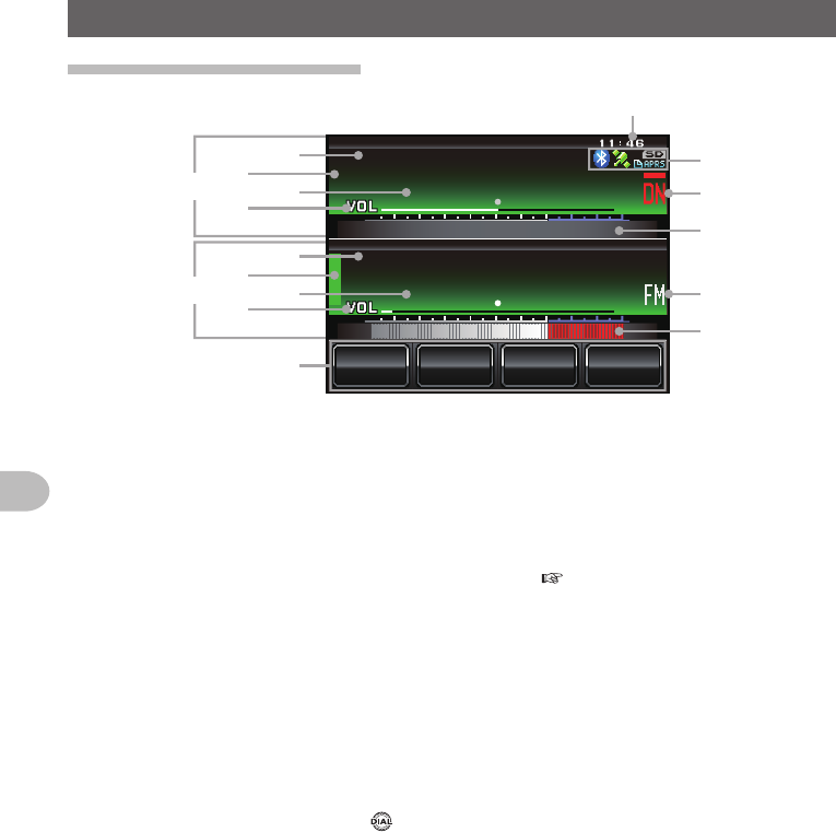
Explanationofthescreen
ᲹᲽᲾᲸᲸ
8(1
᳀ᲾᲸ
ᲽᲸᲸ61-;1Ჺ
/76'
5%12'
/8 53.
B➁
➂
➂
➁
A
➄
➅
➈
➈
➇
➆
➅
➄➃
➃
➀
A Band A display area
B Band B display area
The characters of the name tag and frequency are displayed in white for the
operating band, and gray for the sub-band.
➀ Touch key display area
Functions to be displayed in the function menu screen can be assigned to the touch
keys. Refer to “Changing the touch key functions” ( P.121) for details.
➁ Status display area
A green bar is displayed during receive and when signals are detected.
The bar will not be displayed when the squelch is turned on.
A red bar is displayed when transmitting.
➂ Tag display area
“VFO” is displayed in the VFO mode.
The memory channel number and the tag are displayed in the memory mode.
➃ Frequency display area
In the memory mode, pressing for one second or longer will display the memory
channel tag.
➄ VOL/SQL level display area
➅ S-meter/transmit power level display, and also partner station information display
➆ Clock/Voltage display area
➇ Icon display area
Bluetooth, APRS, micro-SD card and GPS icons are displayed when each function is
in use.
➈ Communication mode display area
The analog and digital modes are indicated using symbols.
A red bar will be displayed above the symbol in the AMS (auto mode). The AMS
automatically matches the communication mode of the received signal.
* Digital communications can operate in Band A only.
Application for FCC / IC
FCC ID: K6620345X40 / IC: 511B-20345X40
19
Before Using
NameandFunctionofEachComponent
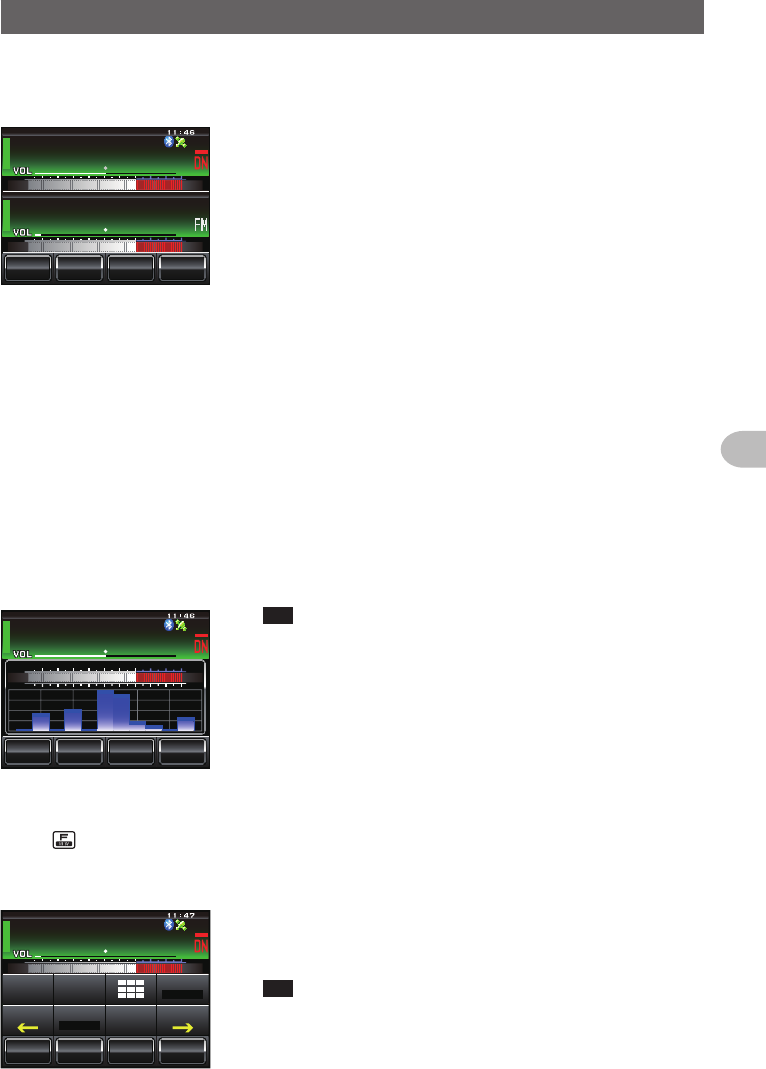
●Dualbandscreen
Band A and Band B will be displayed at the top and bottom.
ᲹᲽᲾᲸᲸ
᳀ᲾᲸ
61-;1Ჺ
/76'
5%12'
/8 53.
8(1
ᲽᲸᲸ
[V/M] The VFO channel and memory channel will be
switched by touching this symbol.
The “V” is displayed in orange in the VFO
mode while the “M” is displayed in orange in
the memory mode.
[SQL] The squelch level can be set after touching this
symbol. The characters are displayed in orange
for 5 seconds during the time that the squelch
level can be set.
[MUTE] The receive audio can be muted by touching
this. The characters are displayed in orange
when the sound has been muted.
[SCOPE] The band scope operation toggles on or
off each time this symbol is touched. The
characters are displayed in orange during the
band scope operation.
●Bandscopescreen
The screen appears as shown, when the band scope is turned on.
5%12'
/76'
ᲽᲿ᳁ᲹᲹ
ᲹᲽᲾᲸᲸ
8(1
/853.
Tip The width of the band scope can be set to either “WIDE” or
“NARROW” under [DISPLAY]→[4BANDSCOPE] in the
set-up menu.
●Function menu screen
When is pressed, the function menu is displayed on the screen under the operating
band.
ᲹᲽᲾᲸᲸ
ᲹᲺ᳀;1-1*#/#
/76'
5%12'
/8 53.
ᲹᲽᲾᲸᲸ
8(1
5-+25'.
1((
&9
6Z294
*+
5%#0 4'8
(9&$#%-
[BACK][FWD]
The menu changes each time these symbols
are touched.
Tip The functions displayed in the menu can be assigned to the
touch keys at the bottom of the display. Refer to Page 121
for details.
Application for FCC / IC
FCC ID: K6620345X40 / IC: 511B-20345X40
20
Before Using
NameandFunctionofEachComponent
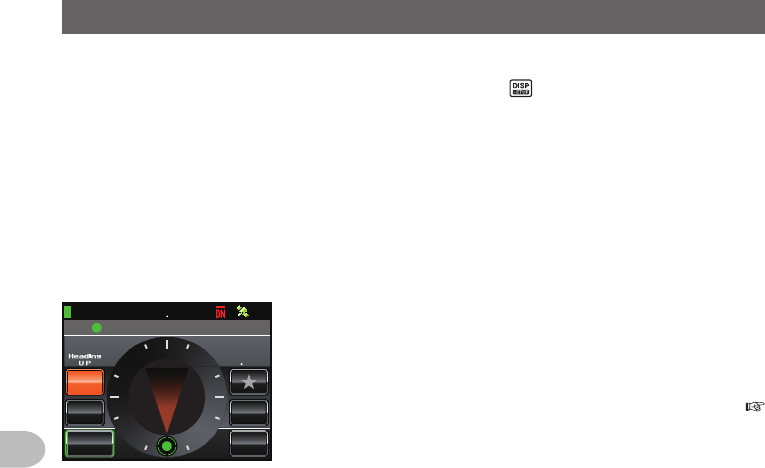
Changethedisplaymode
The display mode will switch in the sequence each time is pressed.
Frequency display screen→Compass/Lat&Lon display screen→Altitude display
screen*→Timer/Clock screen*→GPS screen*
* This screen will be displayed when [DISPLAY]→[1DISPLAYSELECT] is set to
“ON” in the set-up menu.
●Compassscreen
The direction of travel of your own station and direction coordinate of the received
station are displayed in the compass screen.
%1/2#55
Ჸ18( ᲹᲽᲸ
᳁Ჸ
&+56#0%'
MO
/;
;4
.Ჺ
.Ჹ
/'/14;
0
9
'
5
᳂
,#<4.᳂
Ჹ
COMPASS Displays the compass settings. There
are two settings, “Heading Up” where the
direction of travel is on top, and “North Up”
where North is always on top.
Refer to “Change the Compass Settings” (
P.94) for details.
DISTANCE When a saved position information is
recalled, the distance from the current
position is displayed.
[YR] When this symbol is touched, the position
of the partner station that is received is
displayed in the compass (when the position
information is included in the signal), and
the symbol is shown in orange.
[MY] When this symbol is touched, the direction of travel of your own station is
displayed in the compass, and this symbol is displayed in orange.
[MEMORY] When this symbol is touched, the position information being displayed is
saved in the memory.
[] When this symbol is touched while the display is green, the position
information saved in the memory under the tag “” is displayed.
When this symbol is touched while the display is blinking, the position
information displayed in the compass will be saved in the memory under
the tag “”.
[L1] When this symbol is touched while the display is green, the position
information saved in the memory under the tag “L1” is displayed.
When this symbol is touched while the display is blinking, the position
information displayed in the compass will be saved in the memory under
the tag “L1”.
[L2] When this symbol is touched while the display is green, the position
information saved in the memory under the tag “L2” is displayed.
When this symbol is touched while the display is blinking, the position
information displayed in the compass will be saved in the memory under
the tag “L2”.
Application for FCC / IC
FCC ID: K6620345X40 / IC: 511B-20345X40
21
Before Using
NameandFunctionofEachComponent
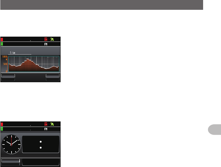
●Altitudedisplayscreen
The altitude of the current location is shown in the bar graph display.
Ჸ1
Ჽ
ᲸᲸ
8( ᲹᲽᲸ
ᲺᲽ᳀O
#.6+67&'
5%#.
'%
.'#4
ALTITUDE Displays the current altitude.
Verticalaxis Represents the altitude.
Horizontalaxis
Represents the distance.
[SCALE] When this symbol is touched, the scale of
the distance changes.
[CLEAR] When this symbol is touched, the graph
display will be cleared (erased).
●Timer/Clockscreen
The current time is shown in analog and digital formats. The date is also shown.
Ჸ
1
8(Ჹ
Ჹ
ᲽᲸ
Ჸ᳁
Ჸ
Ჸ
/1&'
ᲺᲸᲺ
ᲸᲹ#7)
ᲽᲸᲸ
[MODE] The mode switches between the lap timer
mode and the countdown timer mode each
time this symbol is touched.
Application for FCC / IC
FCC ID: K6620345X40 / IC: 511B-20345X40
22
Before Using
NameandFunctionofEachComponent
Ჸ
ᲸᲸᲸ Ჸ
ᲸᲸᲸ ᲺᲹ
/1&'
6+/'4
.#25612
Ჸ
1
8(Ჹ
ᲽᲸ
Ჸ
ᲽᲸᲸ
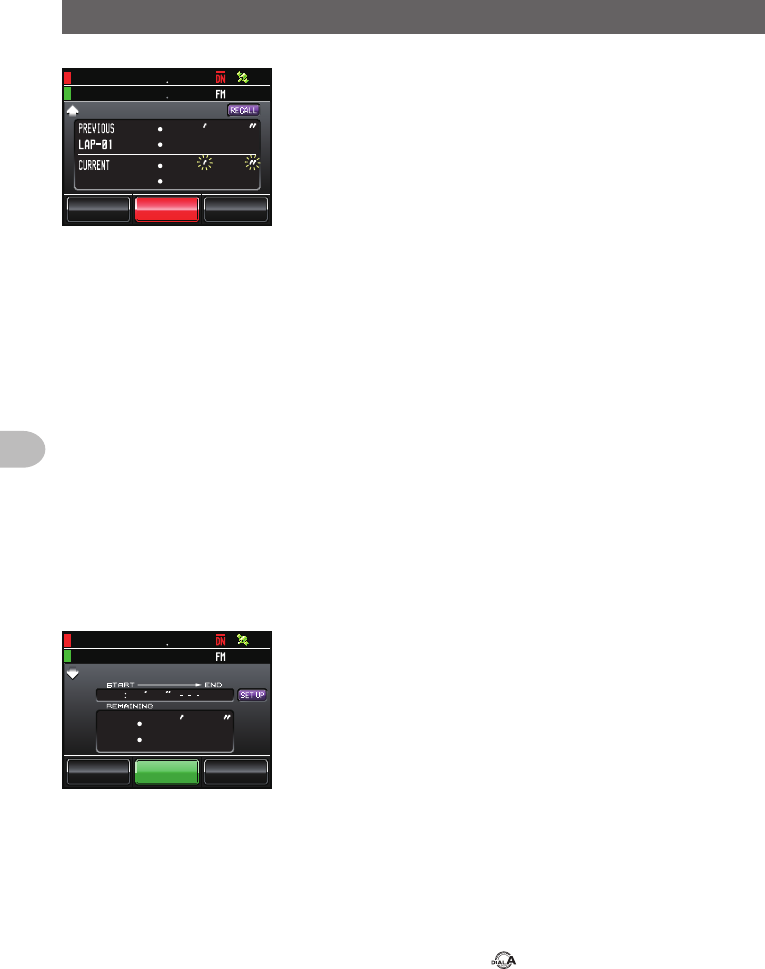
●Laptimerscreen
[START] The count starts when this symbol is
touched.
[LAP] The lap time is then saved in the memory (a
maximum of 99 lap times can be saved) and
displayed in the upper lap display window
when this symbol is touched.
The lap time (of the new interval) being
measured will be displayed in the lower lap
display window.
[STOP] The count stops when this symbol is
touched.
[RECALL] When this symbol is touched, the lap time
saved in the memory is shown in the upper
lap display window while the split time is
shown below. When there are multiple lap
times, touch [][] to move between the
lap times.
Touch [RECALL] again to return to the
measurement screen.
[RESET] The counter is reset when this symbol is
touched.
ᲽᲸᲹ
Ჸ
ᲸᲸᲸ
ᲽᲸ
ᲸᲺ
Ჸ
%1706& 1906+/'4
/1&' 56#46 4'5'6
Ჸ1
Ჽ
ᲸᲸ
8( ᲹᲽᲸ
●Countdowntimerscreen
[START] The count starts when this symbol is
touched.
[STOP] The count stops when this symbol is
touched.
[RESET] The counter is reset when this symbol is
touched.
[SETUP] The count time can be changed (from 1
minute to 99 hours and 59 minutes) when
this symbol is touched. Each time this
symbol is touched, the setting will switch
from “Hours” to “Minutes” to “Confirm”. The
time can be changed by touching [-] and [+]
or turning .
Application for FCC / IC
FCC ID: K6620345X40 / IC: 511B-20345X40
23
Before Using
NameandFunctionofEachComponent
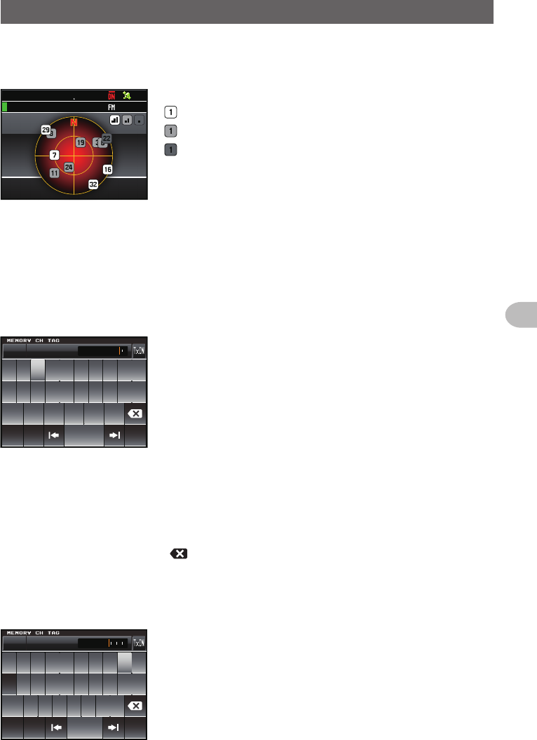
●GPSscreen
The GPS satellite statuses are shown with numbered icons.
)25+0(1
Ჸ1
Ჽ
ᲸᲸ
8( ᲹᲽᲸ
1,2,etc. Received satellite number
Signal strength High
Signal strength Medium
Signal strength Low
Input the character
The keyboard screen is displayed when entering a memory channel tag or the call sign
of your own station.
●Numbersandsymbolsinputscreen
ᲹᲺ
Ჽ ᲾᲿ᳀᳁᳂
"
#$% 5RCEG
'06
!
@
ᲹᲺ
Ჹ ᲾᲸᲾᲸᲸ 61-;1᳂
[ABC] The screen changes to the alphabet input
screen when this symbol is touched.
[123#%^] The screen changes to the input screen for
numbers and symbols each time this symbol
is touched.
[←][→] The cursor in the input field moves left and
right when these symbols are touched.
[ENT] The entered characters are confirmed and
the display returns to the previous screen
when this symbol is touched.
[BACK] The display returns to the previous screen
when this symbol is touched.
[] One character to the left of the cursor is
erased when this symbol is touched.
●Alphabetinputscreen
39'46;7+12
#5&()*,-.
<:%8$0/
#$%
5RCEG
%CRU
'06
@
ᲹᲺ
Ჹ ᲾᲸᲾᲸᲸ 61-;1
[Caps] The input switches between small and
capital letters input each time this symbol is
touched.
Application for FCC / IC
FCC ID: K6620345X40 / IC: 511B-20345X40
24
Installation and Connection
InstallationandConnection
InstallingtheRadio
Precautionsduringinstallation
Note the following when installing this radio.
Do not install the radio in a place where there is extreme vibration, where there is a
lot of dust, excessive humidity or high temperature, or where it is exposed to direct
sunlight.
Install the radio in a well ventilated position, so heat release is not obstructed
because the heat sink gets hot when transmitting for a long periods of time.
Do not place any objects on top of the main body.
Do not lift up or hold the controller by holding the knob or control cable.
A regulated, negative ground 13.8 V DC power supply is required for this radio.
Check that the car battery is a negative ground 12 V system when using this radio in
a mobile unit. Never connect this radio to the 24 V battery of a large vehicle.
Never connect this radio to a 120 V AC power source.
Note that there is a risk that hum and noise may be introduced, depending on the
installation condition and the external power source used.
Install the device as far away as possible from the TV and radio to avoid TV and radio
interference (TVI, BCI).
In particular, do not install this radio near indoor antenna elements.
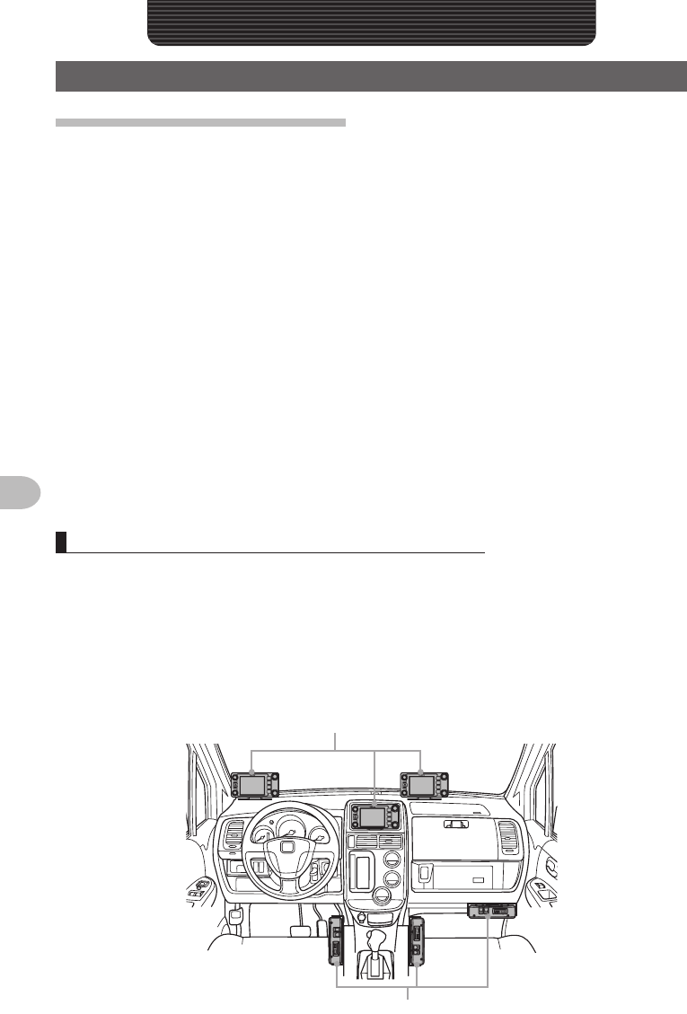
Installation location when used in a mobile unit
●Controller
It is recommended that the controller be installed on top of the car dash board or in front
of the center console. Refer to Page 28 on how to install the controller.
●Mainbody
It is recommended that the main body be installed below the car dash board or to the
side of the center console. Refer to Page 27 on how to install the main body.
Controller
Radio main body
Application for FCC / IC
FCC ID: K6620345X40 / IC: 511B-20345X40
25
Installation and Connection
InstallingtheRadio
Abouttheantenna
A good antenna installation is extremely important for transmission and reception
purposes. Note the following, as the type and characteristics of the antenna largely
determines whether the performance of the radio can be fully realized.
• Use an antenna that suits the installation conditions and application objective.
• Use an antenna that suits the operating frequency band.
• Use an antenna and a co-axial cable with a characteristic impedance of 50Ω.
• Adjust the VSWR (standing wave ratio) until it is 1.5 or less for an antenna with an
adjusted impedance of 50Ω.
• Keep the co-axial cable routing length as short as possible.
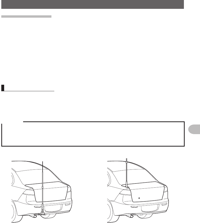
Install the antenna
●Antennainstallationinamobileunit
Mount the antenna base at the rear of the car (rear bumper, trunk, rear gate, etc.) and
then attach the antenna to the base.
Cautions
zEnsure that the antenna base is securely grounded to the car body.
zAvoid routing the co-axial cable enclosed with a commercial car antenna cable.
zDo not allow rain water or moisture to penetrate the cable or connectors when laying the co-axial
cable inside the car.
Bumper type Trunk type
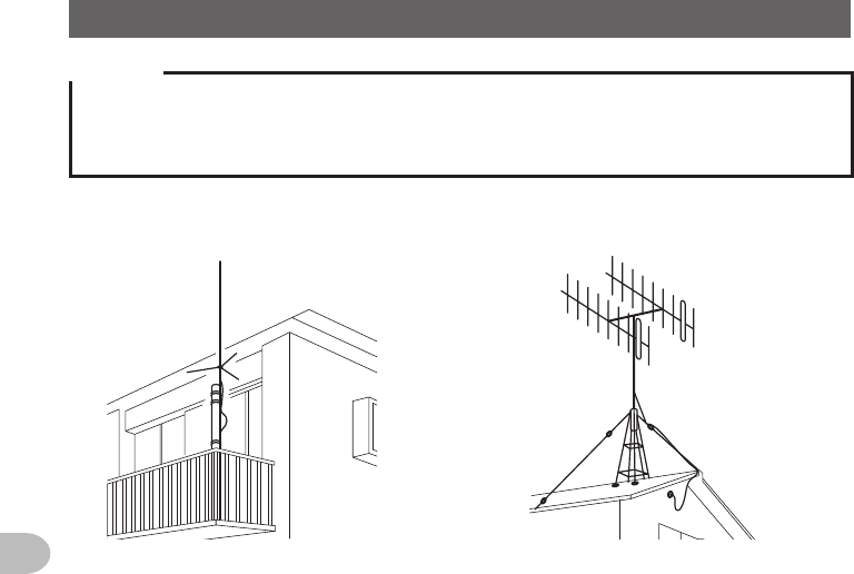
●Antennainstallationinafixedstation
There are omni-directional, and directed array antennas for use in an outdoor setting.
• Omni-directional antennas such as the GP (Ground Plane) antenna are suitable for
communications between a local station and mobile stations in all direction.
• Directional antennas such as the Yagi antenna are suitable for communications
between a base station and a remote station in a specific direction.
Application for FCC / IC
FCC ID: K6620345X40 / IC: 511B-20345X40
26
Installation and Connection
InstallingtheRadio
Cautions
zCreate a loop (slack) in the co-axial cable directly underneath the antenna and fasten it so that the
weight of the cable does not pull on the antenna or connector itself.
zInstall the antenna taking into consideration the securing supports and how the guying wires are
positioned, so that the antenna does not fall over or get blown away in strong winds.
GP antenna
<Veranda Mounted Example>
Yagi antenna
<Roof Mounted Example>
Application for FCC / IC
FCC ID: K6620345X40 / IC: 511B-20345X40
27
Installation and Connection
InstallingtheRadio
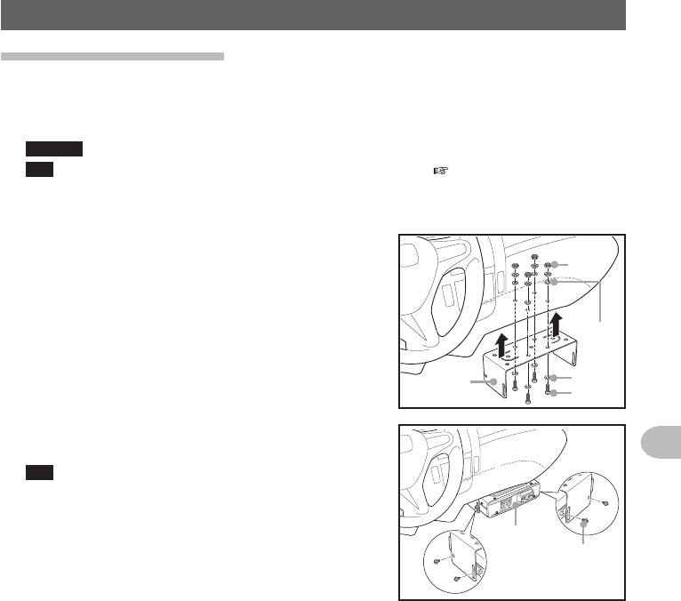
Installingthemainbody
Install the main body using the provided MMB-36 bracket.
1 Select the installation location
Caution Select a location where the antenna coax and power cable can be securely attached.
Tip Also refer to “Installation location when used in a mobile unit” ( P.24).
2 Drill four 6 mm diameter holes in the location where the bracket is to be mounted,
matching the positions of the bolting holes of the bracket
3 Attach the bracket using the provided bolts, nuts
and washers Nut
Washer
Washer
Bolt
Bracket
4 Fasten the main body to the bracket, using the
provided flange bolts, as shown in the drawing
Tip The mounting angle can be changed depending on
the securing position of the flange bolts.
Flange bolt
Main body
Application for FCC / IC
FCC ID: K6620345X40 / IC: 511B-20345X40
28
Installation and Connection
InstallingtheRadio
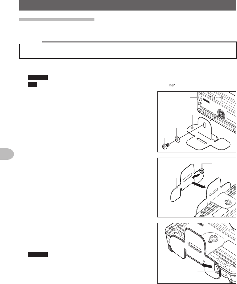
Installingthecontroller
Install the controller using the provided bracket.
Caution
The bracket can be bent by hand to match the location where the controller is going to be installed.
Take due care not to injure yourself when bending the bracket.
1 Select the installation location
Caution Select a stable, flat location with as few dents and protrusions as possible.
Tip Also refer to “Installation location when used in a mobile unit” ( P.24).
2 Fix the bracket to the controller using the
provided screws and washers, as shown in the
drawing
コントローラ
ブラケット
ネジ
ワッシャー
Controller
Bracket
Washer
Screw
3 Peel off the protective seal from one side of the
provided two-sided adhesive sheet, and paste it
onto the bottom of the bracket
保護
シール
両面接着
シート
Protection
seal
Two-sided
adhesive
sheet
4 Peel off the other protection seal from the
underside of the two-sided adhesive sheet pasted
onto the bracket, and then stick the bracket to the
installation location
Caution Remove all dirt and dust from the installation
location before affixing the bracket.
保護シール
Protection seal
Application for FCC / IC
FCC ID: K6620345X40 / IC: 511B-20345X40