Yaesu Musen 20345X40 SCANNING RECEIVER User Manual FTM 400DR Operating Manual
Yaesu Musen Co., Ltd. SCANNING RECEIVER FTM 400DR Operating Manual
Contents
- 1. User Manual
- 2. User Manual 1
- 3. User Manual 2
- 4. User Manual 3
- 5. User Manual 4
- 6. User Manual 5
- 7. User Manual 6
- 8. User Manual 7
- 9. User Manual 8
- 10. User Manual 9
- 11. User Manual 10
- 12. User Manual 11
- 13. User Manual 12
- 14. User Manual 13
- 15. User Manual 14
- 16. User Manual 15
- 17. User Manual 16
- 18. User Manual 17
- 19. User Manual 18
- 20. User Manual 19
- 21. User Manual 20
- 22. User Manual 21
User Manual

C4FM FDMA 144/430 MHz
DUAL BAND DIGITAL TRANSCEIVER
OPERATING MANUAL
YAESU MUSEN CO., LTD.
Tennozu Parkside Building
2-5-8 Higashi-Shinagawa, Shinagawa-ku, Tokyo 140-0002 Japan
YAESU USA
6125 Phyllis Drive, Cypress, CA 90630, U.S.A.
YAESU UK LTD.
Unit 12, Sun Valley Business Park, Winnall Close
Winchester, Hampshire, SO23 0LB, U.K.
YAESU HK LTD.
Unit 1306-1308, 13F., Millennium City 2, 378 Kwun Tong Road,
Kwun Tong, Kowloon, Hong Kong
FTM-400DR
FCC ID: K6620345X40
IC: 511B-20345X40

1
Before Using This Equipment
Before Using This EquipmentContents
Programmable Memory Scan (PMS) ................... 37
Writing into a Programmable Memory ............. 37
Performing Programmable Memory Scan ....... 39
Useful Functions .................................................... 41
Dual Reception (DW) Functions ............................... 41
Dial Dual Reception
VFO mode → Home channel ......................... 41
Memory Dual Reception
Memory channel → Home Channel ............... 42
Using the DTMF Function......................................... 42
Sending the Registered DTMF Code ....................... 43
Sending a DTMF Code Manually ............................. 44
Communicating with a Specific Remote Station . 45
Using the Tone Squelch Function ............................. 45
Selecting a Tone Frequency ................................ 46
Searching for the Frequency of the Tone Squelch
Used by the Remote Station ................................ 46
Selecting a DCS Code ......................................... 47
Searching for the Frequency of the DCS Used by
the Remote Station .............................................. 47
Notification of Call from a Remote Station by the
Bell............................................................................ 48
Calling Only a Specific Station New Pager
Function .................................................................... 48
Flow of Operation to Use the Pager Function ...... 48
Setting the Code of Your Station .......................... 49
Turning on the New Pager Function .................... 49
Calling a Specific Station ..................................... 50
Being Called by the Remote Station (Standby
Operation) ............................................................ 51
Functions Used as Needed.................................... 52
Setup Menu .............................................................. 52
Settings for the Setup Menu ................................ 52
Setup Menu Operations List ................................ 52
Apply settings to contents displayed on screen. .. 59
Setting the Background Color of the Screen ....... 60
Setting the Frequency Width for Band Scope ...... 60
Adjusting the LCD Backlight Brightness Level ..... 61
Adjusting LCD Contrast ....................................... 61
Switching between Time and Voltage display ...... 62
Adjusting volume respectively to A/B Bands. ....... 62
Setting the Display Method for Memory
Channels .............................................................. 63
Setting the Squelch Type for transmission ........... 63
Setting the display format for the Clock Function 64
Setting the Time Zone .......................................... 65
Setting the Automatic Repeater Shift ................... 65
Setting the Clock Shift of the Microcomputer ....... 66
Setting the Program Keys on the Microphone ..... 66
Setting the Bandwidth to Scope ........................... 67
Setting the unit of measurement to be displayed . 67
Automatically Turning Off the Power
APO Function....................................................... 68
Restricting the Continuous Transmission Time
TOT Function ....................................................... 68
Setting PIN Code for a BLUETOOTH headset .... 69
Selecting Datum for GPS function. ...................... 69
Before Using This Equipment ................................. 3
Safety Precautions (Be Sure to Read) ....................... 3
Before Transmitting Radio Waves .............................. 8
Accessory and Option ................................................ 9
Attaching Accessory Items ....................................... 10
Connecting the Panel Screen to the Main Unit .... 10
Connect the accessory microphone (MH-48). ..... 10
Setting up the Panel Screen with the accessory
bracket. .................................................................11
Names for various parts, Functional Parts and their
Functions. ................................................................. 12
Description for Panel Screen ............................... 12
Description about the Screen............................... 13
Description of Microphone (MH-48) ..................... 16
Using the microSD Memory Card ............................. 17
Usable microSD memory cards. .......................... 17
Precautions for when using a microSD memory
card. ..................................................................... 18
Installing/removing microSD memory card .......... 18
Formatting the microSD Memory Card ................ 19
Basic Operation ...................................................... 20
Communication......................................................... 20
Changing the Beep Sound. .................................. 20
Using the Timer Function ..................................... 21
The ALTITUDE function for measuring altitude. ... 22
Locking Keys and Switches ................................. 22
Changing Transmission Output............................ 24
Adjusting Microphone Sensitivity (MIC GAIN) ..... 24
Other Settings........................................................... 25
Adjusting Time ..................................................... 25
Muting Sounds ..................................................... 26
Adjusting Squelch Level....................................... 26
Manually switching frequency steps .................... 27
Resetting applied settings .................................... 27
Repeater Operation ................................................ 28
Repeater Operation .................................................. 28
Communicating Via the Repeater ........................ 28
Communicating Via the Repeater Using a Tone
Signal Other Than the 88.5Hz Tone Signal .......... 28
Using Memory ......................................................... 30
Wide variety of Memory Functions ........................... 30
Registering to Memory ......................................... 30
Split Memory ........................................................ 31
Recalling a Memory Channel ............................... 31
Recalling the Home Channel ............................... 32
Returning to the Previous Frequency .............. 32
Deleting Memory .................................................. 32
Changing the display method of Memory Tags.
........................................................................ 33
Scanning Function ................................................. 34
Using the Scanning Function.................................... 34
VFO Scan ............................................................ 34
Canceling Scanning ........................................ 34
Setting a Reception Method When Scanning
Stops ............................................................... 34
Memory Scanning ................................................ 35
FCC ID: K6620345X40
IC: 511B-20345X40

2
Before Using This Equipment
Contents
Setting the GPS Device to Use ............................ 70
Setting Time for Accessing GPS .......................... 70
Communicating by crossing A Band and B band
frequencies .......................................................... 71
Setting USB Camera to Use. ............................... 71
Setting operations of BLUETOOTH Headset to
Use....................................................................... 72
Setting Operations of the Voice Announcement
Function ............................................................... 73
Writing Group ID to microSD Memory Card ......... 74
Registering Preset ............................................... 75
Recalling the Registered Preset. ......................... 75
Deleting Memory Channels.................................. 76
Sorting Registered Memory Channels in Order. .. 76
Deleting Settings Configured for APRS
Function. .............................................................. 77
The Clone Function For copying settings to
another FTM-400DR ............................................ 77
FTM-400DR Specifications .................................... 79
FCC ID: K6620345X40
IC: 511B-20345X40
3
Before Using This Equipment
Before Using This Equipment
Safety Precautions (Be Sure to Read)
Be sure to read the safety precautions to use this product safely.
We are not liable for failures and other problems caused due to misuse or use of this
product by you or a third party as well as the damages caused through use of this
product by you or a third party except in the case where we are ordered to pay for
damages under the laws.
Types and Meanings of Symbols
DANGER Indicates an imminently hazardous situation which, if not
avoided, could result in death or serious injury.
WARNING Indicates a potentially hazardous situation which, if not
avoided, could result in death or serious injury.
CAUTION
Indicates a potentially hazardous situation which, if not
avoided, may result in minor or moderate injury or only
property damage.
Types and Meanings of Legends
Indicates a prohibited item not to be done in order to use this product safely.
For example, indicates that the product should not be disassembled.
Indicates an obliged item to be done in order to use this product safely.
For example, indicates that the power plug should be removed.
DANGER
Do not use this product in “an area
where use of it is prohibited”, e.g.,
inside the hospital, airplane, or
train.”
This product can affect electronic or
medical devices.
Do not use this product while riding
a bicycle or driving a car. Accidents
can result.
Be sure to stop the bicycle or car at a
safe place before using this product.
Those who are carrying a medical
device such as a cardiac pacemaker
should not perform transmission
near it. When performing
transmission, use an external
antenna and keep away from the
external antenna as far as possible.
The radio wave emitted from this
product can cause the medical device
to malfunction and result in an accident.
Do not use this product or the
battery charger in a place where
inflammable gas is generated.
A fire or explosion can occur.
FCC ID: K6620345X40
IC: 511B-20345X40
4
Before Using This Equipment
Safety Precautions (Be Sure to Read)
Do not perform transmission in a
crowded place for the safety of the
persons carrying a medical device
such as a cardiac pacemaker.
The radio wave emitted from this
product can cause the medical device
to malfunction and result in an accident.
Do not touch the liquid leaking from
the battery pack with bare hands.
The liquid that has stuck to your skin or
entered in your eye can cause chemical
burn. In such a case, consult the doctor
immediately.
Do not solder or short-circuit the
terminal of the battery pack.
A fire, leak, overheating, explosion, or
ignition can result.
Do not carry the battery pack together
with a necklace or hair pin. A short
circuit can result.
If it starts thundering when
the external antenna is used,
immediately turn off this product
and disconnect the external antenna
from it.
A fire, electrical shock, failure can
result.
WANING
Do not use this product at a voltage
other than the specified power
supply voltage.
A fire or electric shock can result.
Do not use the battery pack for any
model other than the specified mode.
A fire, leak, overheating, explosion, or
ignition can result.
This product has a waterproof
structure and conforms to “IPX5”
when the included antenna and
battery pack are installed and rubber
caps are securely attached to the
MIC/SP jack, EXTDC IN jack, DATA
terminal, and micro SD slot. If this
product gets wet, wipe it with a dry
cloth, etc. without leaving it as it is.
Leaving this product in a wet condition
can degrade its performance, shorten
its life, or cause a failure or electrical
shock.
Do not perform transmission for a
long period.
The main body can overheat, resulting
in a failure or burn.
Do not disassemble or make any
alteration to this product.
An injury, electric shock, or failure can
result.
Do not handle the battery pack or
charger with wet hands. Do not
insert or remove the power plug with
wet hands.
An injury, leak, fire, or failure can result.
If smoke or strange odor is emitted
from the main body, battery pack,
or battery charger, immediately turn
off this product, remove the battery
pack, and remove the power plug
from the outlet.
A fire, leak, overheating, damage,
ignition, or failure can result. Contact
the shop from which you purchased
this product or our Amateur Customer
Support.
Do not use the battery pack which is
externally damaged or deformed.
A fire, leak, hating, explosion, or ignition
can result.
Do not use any battery charger
which is not specified by us.
A fire or failure can result.
Keep the terminals of the battery
pack clean.
If stained, a fire, leak, overheating,
explosion, or ignition can result.
FCC ID: K6620345X40
IC: 511B-20345X40
5
Before Using This Equipment
Safety Precautions (Be Sure to Read)
If charging of the battery pack
cannot be completed after lapse
of the specified time, immediately
remove the power plug of the battery
charger from the outlet.
A fire, leak, overheating, explosion, or
ignition can result.
CAUTION
Do not dangle or throw this product
by holding its antenna.
This product can hit and injure
someone. In addition, doing so can
result in a main body failure or damage.
Do not use this product in a crowded
place.
The antenna can hit someone, resulting
in a injury.
Do not place this product in a place
subject to direct sunlight or near a
heater.
This product can deform or discolor.
Do not place this product in a humid
or dusty place.
A fire or failure can result.
During transmission, keep the
antenna away from you as far as
possible.
Long-time exposure to electromagnetic
waves can have a negative impact on
your health.
Do not clean the case with thinner or
benzene.
Use a soft, dry cloth to clean the case.
If you do not use this product for a
long period, turn it off and remove
the battery pack for safety.
Do not give a strong shock to or
throw this product.
A failure can result.
Keep magnetic cards and video tape
away from this product.
The data recorded on cash cards or
video tape can be erased.
Do not use the earpiece microphone,
earphones, or headphones at an
extremely high volume level.
Hearing impairment can result.
Keep this product out of reach of
children.
An injury, etc. can result.
Install the hand strap and belt click
securely.
If they are installed improperly, they
can fall down, resulting in an injury or
damage.
Do not place a heavy thing on the
power cord of the battery charger.
The battery cord can be damaged,
resulting in a fire or electric shock.
Do not use the included battery
charger to charge any battery pack
which is not specified by us.
A fire can result.
Do not perform transmission near
the TV or radio.
Radio disturbance can occur in this
product, TV, or radio.
Do not use any products other than
the options specified by us.
A failure can result.
When the battery charger is not in
use, remove its power plug from the
outlet
FCC ID: K6620345X40
IC: 511B-20345X40
6
Before Using This Equipment
Safety Precautions (Be Sure to Read)
Charge the battery pack within the
temperature range from 5°C to 35°C.
Charging the battery pack outside this
temperature range can cause leak,
overheating, decrease in performance,
or reduction in service life can result.
When unplugging the power cord of
the battery charger, be sure to hold
the power plug.
Pulling the power cord can damage it
and cause a fire or electronic shock.
Before discarding the worn battery
pack, affix tape or the like to its
terminals.
When using this product in a hybrid
or fuel-saving car, be sure to check
with the automobile manufacturer if
the it can be used in that car.
Noise generated by an onboard
electrical device (inverter, etc.) can
disable normal reception by this
product.
FCC ID: K6620345X40
IC: 511B-20345X40

7
Before Using This Equipment
Safety Precautions (Be Sure to Read)
About Waterproofi ng Feature Conforming to IPX5
When the included antenna and battery pack are installed and the MIC/SP jack, EXT
DC IN jack, DATA terminal, and micro SD slot are securely covered with rubber caps,
this product can withstand continuous 30-minute immersion in water at depth of 1
m. To ensure this waterproofing feature, be sure to check the following points before
use.
Check for damages, deterioration, and dirt.
Antenna rubber, key switch rubber, MIC/SP jack, EXT DC IN jack, DATA terminal, micro SD
slot rubber cap, and battery pack joint.
Cleaning
When this product is contaminated with seawater, sand, or dirt, rinse with fresh water, and
then wipe with a dry cloth immediately.
Recommended maintenance interval
It is recommended that you ask for maintenance of this product when one year has passed
since purchase or previous maintenance or when any damage or deterioration is found. Note
that the maintenance service is subject to fees.
Do not immerse this product in the following liquids:
Sea, pool, hot spring, water containing soap, detergent, or bath additive, alcohol, or
chemicals
Do not leave this product for a long time in the following places:
Bathroom, kitchen, or humid place
Other precautions
Since this product is not totally waterproof, it cannot be used in water.
FCC ID: K6620345X40
IC: 511B-20345X40

8
Before Using This Equipment
Before Transmitting Radio Waves
If you are informed that the radio waves emitted from your amateur station are
interfering with reception by the TV, radio, etc., of a neighbor, you should stop emitting
the radio waves and check whether any problem of interference and its degree if it
exists.
FCC ID: K6620345X40
IC: 511B-20345X40

9
Before Using This Equipment
Accessory and Option
×××× ×××× ××××
×××× ×××× ××××
×××× ×××× ××××
FCC ID: K6620345X40
IC: 511B-20345X40
10
Before Using This Equipment
Attaching Accessory Items
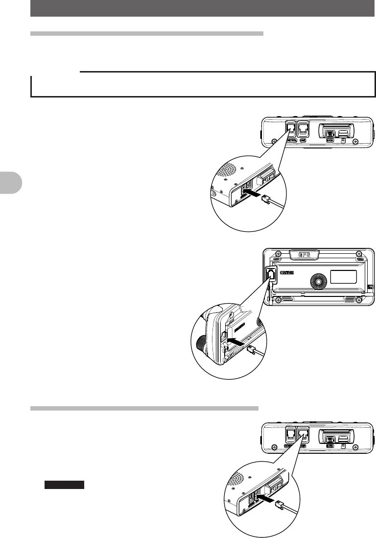
Connecting the Panel Screen to the Main Unit
Connect the Panel to the Main Unit.
Precaution
zMake sure to turn off the Main Unit when connecting the Panel Screen to the Main Unit.
1 Connect the accessory cable to the
Main Unit.
Connect the cable to the
[CONTROL] port of the Main Unit.
2 Connect the cable to the Panel
Screen.
Connect the cable to the
[CONTROL] port of the Panel
Screen.
Connect the accessory microphone (MH-48).
1 Insert the microphone (MH-48) into the MIC port of
the Main Unit.
As shown in the image on the right, connect
the accessory microphone (MH-48) to the
MIC port of the Main Unit.
Reference • When removing the microphone, pull it
out while pressing [PUSH ▼].
FCC ID: K6620345X40
IC: 511B-20345X40
11
Before Using This Equipment
Attaching Accessory Items
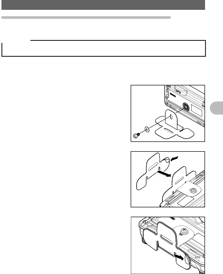
Setting up the Panel Screen with the accessory bracket.
Set the Panel Screen up with the accessory bracket.
Precaution
• The bracket can be shaped by hand to fit where the Panel Screen is to be set. Be careful not to
injure yourself when manipulating the bracket into the desired shape.
1 Choosing where to set the Panel Screen.
Decide where to set the Panel Screen.
2 Attach the bracket to the Panel Screen.
As shown on the figure, attach the bracket to
the panel using the enclosed screws.
3 Attach the bracket using double-sided
adhesive tape.
Remove the protective film on one side of the
enclosed double-sided adhesive tape and
paste it to the bottom of the bracket.
4 Attach the Panel Screen to the desired
location.
Remove the protective film on the remaining
side of the double-sided adhesive tape
and paste the Panel Screen to the desired
location of the vehicle.
FCC ID: K6620345X40
IC: 511B-20345X40
12
Before Using This Equipment
Names for various parts, Functional Parts and their Functions.
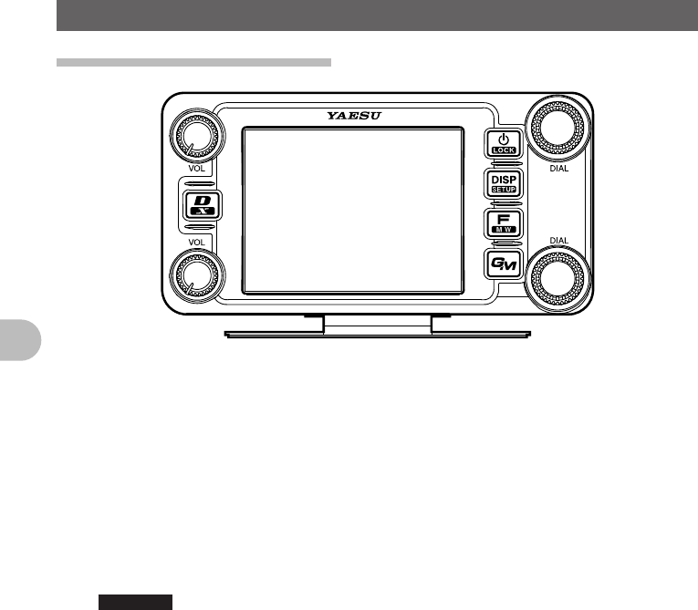
Description for Panel Screen
O Pressing O shortly switches between operating bands.
When selecting operating band, press the O shortly to fast forward the MHz
indication.
Pressing and holding O over 1 second switches the operating band in units of
5MHz
v The volume can be adjusted with v.
P Power can be switched ON/OFF by pressing and holding P over 1 second.
Pressing P shortly while the power is ON switches the key lock ON/OFF.
M Pressing the M shortly changes the view of the Display.
Reference See pages xx for details on the view of the Display.
Pressing and holding M over 1 second displays the Setup Menu.
F Pressing F shortly displays the Function Menu.
Pressing and holding F over 1 second switches to the Memory Recording
Mode.
D Pressing D shortly switches the ARTS D ON/OFF.
Pressing and holding D over 1 second stores ARTS D Group information of
your station to the microSD memory card.
Pressing D while transmitting sends ARTS D Group information of your station
to the destination station.
% Pressing the % shortly switches between Analog/Digital Mode.
Pressing and holding % over 1 second starts WiRES X.
FCC ID: K6620345X40
IC: 511B-20345X40

13
Before Using This Equipment
Names for various parts, Functional Parts and their Functions.
Description about the Screen
[V/M] Tapping [V/M] switches between VFO
channels and Memory Channels.
[SQL] Squelch level can be adjusted by tapping
[SQL].
[MUTE] Tapping [MUTE] mutes reception tone.
[SCOPE] Tapping [SCOPE] switches the Band Scope
Function ON/OFF.
When the Band Scope Function is ON, it appears as follows:
←Operating Frequency
←VOL Level/SQL Level
←S Meter/Destination Station Information
←Band Scope Area
Pressing M shortly switches to the next screen.
●ARTS/GMS Screen
[BACK] Returns to the previous screen.
[LIST] Displays the list of received messages.
FCC ID: K6620345X40
IC: 511B-20345X40

14
Before Using This Equipment
Names for various parts, Functional Parts and their Functions.
●BACK TRACK Screen
[Compass Unit] Tapping [Compass Unit] saves
current location information.
[L1] Tapping [L1] displays location
information registered to L1.
[L2] Tapping [L2] displays location
information registered to L2.
[TX] Tapping [TX] transmits the current location information/ID/TAG of your station
to the destination station.
[RCVD] Tapping [RCVD] selects BACK TRACK ON/OFF for the destination station.
When the BACK TRACK is ON, it appears in White.
When the BACK TRACK is OFF, it appears in Grey.
When a signal from the destination station with it’s location information is
received, it appears in orange.
●NAVIGATION Screen
[Heading UP] Tapping [Heading UP] switches
between Heading Up and Nose Up.
[DESTINATION] Tapping [DESTINATION] displays
the Point List to start navigation.
[CLEAR] Tapping [CLEAR] stops navigation.
[CURRENT] Tapping [CURRENT] displays the
current location information.
[LOCATION]
The following screen appears when displaying the Point List.
[BACK] Tapping [BACK] returns to the previous
screen and puts the navigation on standby.
[NAVI] Tapping [NAVI] returns to the previous
screen and starts navigation.
[EDIT] Tapping [EDIT] allows you to edit names of
Point List.
[DEL] Tap [DEL] allows you to delete Point List.
[SORT] Tapping [SORT] sorts Point Memory in the
predetermined order.
FCC ID: K6620345X40
IC: 511B-20345X40

15
Before Using This Equipment
Names for various parts, Functional Parts and their Functions.
●ALTITUDE Screen
[CLEAR] Tapping [CLEAR] deletes data being
displayed.
[Altitude Scale] Tapping [Altitude Scale] allows
you to change measurement unit of
altitude being displayed.
[Distance Scale] Tapping [Distance Scale] allows you
to change the measurement unit of
distance being displayed.
[CURRENT] Tapping [CURRENT] displays
detailed location information.
[LOCATION]
●TIMER/CLOCK Screen
[MODE] Tapping [MODE] toggles through
[CLOCK], [LAP COUNTER], [DOWN
COUNTER].
●LAP Timer Screen
[START] Tapping [START] starts the Counter.
[STOP] Tapping [STOP] stops the Counter.
[LAP] Tapping [LAP] displays LAP value
measured by Counter.
[RESET] Tapping [RESET] resets LAP value
measured by Counter.
[RECALL] Tapping [RECALL] will display LAP value
measured by Counter.
●Down Timer Screen
[SETUP] Tapping [SETUP] displays setting screen
for time measurement.
[RESET] Tapping [RESET] returns to time
measurement display screen.
FCC ID: K6620345X40
IC: 511B-20345X40

16
Before Using This Equipment
Names for various parts, Functional Parts and their Functions.
●GPS INFO Screen
[CURRENT] Tapping [CURRENT] displays detailed
location information.
[LOCATION MEMORY]
Save present location information to
memory.
[1] Recieving Satellite Number
[1] Signal Strength High
[1] (Halftone 20%) Signal Strength
Medium
[1] (Halftone 50%) Signal Strength Low
Description of Microphone (MH-48)
[UP] Raises the frequency up one step.
[DOWN] Lowers the frequency down one step.
[1] to [0] Input numbers and alphabet.
[*] Switch between VFO/MEMEORY of
operating band.
[#] Registers frequency to memory.
[A] Switches operating band to A band.
[B] Switches operating band to B band.
[C] Adjust DQL level.
[D] Switch the view of DISPLAY.
[P1] Sets SQL to OFF.
[P2] Moves to frequency set as HOME.
[P3] RPT SHIFT
[P4] TX POWER
[LOCK] Locks keys [UP] and [DOWN] to prevent
miss operation.
[LAMP] Lights the lamp on the Microphone.
Reference
• Functions for [P1] to [P4] can be changed in [OPTION] → [10 MIC PRG KEY] of the Setup Menu.
FCC ID: K6620345X40
IC: 511B-20345X40

17
Before Using This Equipment
Using the microSD Memory Card
Using a microSD memory card allows for the following functions.
The function to backup this unit’s information.
The function to save Memory Data.
The function to save the Set Mode.
The function to save data other than images.
The function to save the GPS Log Data.
The function to save photo data captured with the optional camera mounted on
microphone (MH-85A11U).
Usable microSD memory cards.
This unit supports microSD memory cards and microSDHC memory cards.
However, operation of commercially sold microSD cards and microSDHC memory cards
are not guaranteed.
Refer to the following list for supported microSDHC memory cards.
FCC ID: K6620345X40
IC: 511B-20345X40
18
Before Using This Equipment
Using the microSD Memory Card
Precautions for when using a microSD memory card.
Do not bend or place heavy objects on top of microSD memory cards.
If a microSD memory card has been formatted with a different device, may obstruct
the proper storage of data. Reformat a memory card with this unit if it has been
formatted with a different device.
Do not remove a microSD memory card or turn off the power of this unit while data is
being saved to a microSD memory card.
Do not insert objects other than a microSD memory card into the microSD memory
card slot.
Do not forcefully remove an inserted microSD memory card.
Do not use microSD memory cards other than those that are specified. Please contact
our Amateur Customer Support for information about specified products.
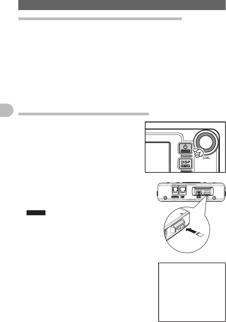
Installing/removing microSD memory card
1 Press and hold P over 1 second.
Turn off the power of the main unit.
2 Insert microSD memory card.
As shown in the figure to the right, insert the
microSD memory card into the slot until it clicks
into place.
Caution • Be careful not to insert the microSD memory
card in the wrong direction.
• Do not touch the terminal of the microSD
card.
“SDCARD” appears in the upper left corner of
the screen.
FCC ID: K6620345X40
IC: 511B-20345X40

19
Before Using This Equipment
Using the microSD Memory Card
Formatting the microSD Memory Card
Follow the instructions below when formatting a new microSD memory card.
Precaution
Formatting a microSD memory card will erase all saved data. Check the data saved to the microSD
memory card in use, before formatting the card.
1 Press and hold M over 1 second.
Set Mode screen appears.
2 Tap [SD].
3 Tap [1 BACKUP].
4 Tap [FORMAT].
[SD CARD PUSH F KEY!] appears on screen.
5 Press F.
[FORMAT? PUSH F KEY!] appears on screen.
Reference Tap [BACK] to cancel format.
6 Press F.
Formatting starts.
Once format is finished, [SD CARD PUSH F KEY!]
appears on screen.
7 Press and hold M over 1 second.
Exit from Set Mode.
FCC ID: K6620345X40
IC: 511B-20345X40

20
Basic Operation
Basic Operation
Communication
1 Press and hold P over 1 second.
Turn on the power.
2 Adjust volume with [VOL].
3 Tap [SQL].
Adjust Squelch
4 Adjust frequency using O.
Reference • The frequency can also be adjusted using [UP],
[DOWN], and [0] to [9] on the microphone.
5 Speak by pressing [PTT] on the microphone.
6 Press and hold P over 1 second.
Turn off the power.
Reference
• The type of radio is set automatically.
• The type of radio can also be changed manually (See page xx).
• The frequency can also be selected with the [UP] and [DOWN] on the microphone.
Changing the Beep Sound.
The operation confirmation sound (Beep Sound), heard when keys are operated, can be
changed.
1 Press and hold M over 1 second.
The Setup Menu appears.
2 Tap [CONFIG].
3 Tap [8 BEEP] and select desired Beep Sound.
The Beep Sound will change in the following order
each time [8 BEEP] is tapped.
[OFF] → [LOW] → [HIGH]
4 Press and hold M over 1 second
The Beep Sound is set and the screen returns to the
previous screen.
FCC ID: K6620345X40
IC: 511B-20345X40
21
Basic Operation
Communication
Using the Timer Function
This unit is equipped with a Lap Timer and Down Timer.
Precaution
zAdjust the internal clock beforehand when using the timer function.(See page 000).
●Using the Lap Timer
1 Press M shortly.
Press M shortly until clock appears.
2 Tap [MODE].
The Lap Timer appears.
3 Tap [START].
The Timer starts.
4 Tap [LAP].
The Lap Time is recorded every time [LAP] is tapped.
5 Tap [STOP].
The Timer stops.
Tapping [RESET] deletes Lap Time.
Tapping [RECALL] displays Lap Time that has been
recorded in the past.
6 Press M shortly.
Exits Timer Screen and returns to the previous screen.
●Using the Down Timer
1 Press M shortly.
Press M shortly a few times until clock appears.
2 Tap [MODE] twice
Down Timer appears.
3 Tap [SETUP].
The setting screen for time measurement appears.
4 Set time with O.
Rotate O and set [TIME] for time measurement.
Tapping [SETUP] applys the selected time.
[MINUTE] can be set in the same way.
FCC ID: K6620345X40
IC: 511B-20345X40

22
Basic Operation
Communication
5 Tap [START].
The Down Timer starts.
Tap [STOP] to pause timer if you want to stop it in the
middle.
When the set time is reached, [00:00’00] appears in green.
6 Press M shortly.
Exits Timer Screen and returns to the previous screen.
The ALTITUDE function for measuring altitude.
The altitude of present location or change of altitude according to traveled distance can
be displayed as a graph.
Precaution
zIn order to use the ALTITUDE function, connect the optional GPS antenna unit.
zIn order to display the ALTITUDE screen, set to [ALTITUDE:ON] of [DISPLAY] → [1 DISPAY
SELECT] in the Top Menu beforehand.
1 Press M shortly.
Press M shortly a few times until ALTITUDE screen appears.
2 Altitude appears.
The present altitude appears on the display.
Tapping [CLEAR] deletes accumulated data of altitude change.
Tapping [LOCATION MEMORY] saves information on present location.
3 Press M shortly.
Press M shortly a few times until the screen returns to the previous one.
Locking Keys and Switches
Oand switches can be locked to prevent accidental changes in radio frequency during
movement.
1 Press P shortly.
[LOCK] appears on the display and the screen returns to the previous one.
Reference To Unlock, press [PTT] shortly again.
[UNLOCK] appears on the display and the screen will return to the previous one.
Reference
• Conditions for automatic Lock can be changed in the Setup Menu (See page 000).
FCC ID: K6620345X40
IC: 511B-20345X40

23
Basic Operation
Switching type of radio (mode) and conducting
communication
In factory settings, this unit is set in [AUTO] mode and automatically selects the
optimum mode (type of radio) according to frequency. The type of radio (mode) can be
manually changed and conduct communication.
Using this unit, communication can be conducted in 4 forms: [AUTO (FM)], [FM],
[NARROW FM], and [AM].
Select the desired mode and conduct communication with the following steps.
1 Press and hold M over 1 second.
The Setup Menu appears.
2 Tap [TX/RX].
3 Tap [MODE] and select desired Mode.
The Mode changes in the following order each time
[MODE] is tapped.
[AUTO (FM)]: Automatically switches to the optimal
type of radio according to frequency
band.
[FM]: Only changes the selected frequency band to
FM Mode.
[Narrow FM]: Only changes the selected frequency
band to NFM Mode.
[AM]: Only changes the selected frequency band to
AM Mode.
Reference Mode can also be selected by pressing v.
5 Press and hold M over 1 second.
The Mode is set and the screen returns to the
previous one.
6 Set frequency with O.
Select frequency for communication.
7 Speak by pressing [PTT] on the microphone.
Speak with about 5cm between microphone and mouth.
8 Release [PTT].
Returns to reception state.
FCC ID: K6620345X40
IC: 511B-20345X40

24
Basic Operation
Switching type of radio (mode) and conducting communication
Changing Transmission Output
The transmission output can be lowered for when communicating with a transceiver
near by, or to reduce battery consumption.
1 Press F.
2 Tap [Tx PWR] and select desired transmission
output.
The Transmission Output changes in the following
order, each time [Tx PWR] is tapped.
[HI (5.0W)] → [LOW (OOW)] → [MID (OOW)]
Reference • Sensitivity can also be selected by pressing O.
Reference
• Avoid long periods of continuous transmission. Doing so
causes temperature of the unit to rise, and may lead to
malfunction or burning injuries due to over heating.
• The current Output level is indicated under [Tx PWR] on the
display.
• [OFF] appears on the display for frequencies where signal
cannot be transmitted.
• This unit is set to [HI] in Factory setting.
Adjusting Microphone Sensitivity (MIC GAIN)
The Microphone Sensitivity can be adjusted.
1 Press and hold M over 1 second.
The Setup Menu appears.
2 Tap [TX/RX].
3 Tap [AUDIO].
4 Tap [3 MIC GAIN] and select desired Sensitivity.
The Sensitivity changes in the following order each
time [3 MIC GAIN] is tapped.
[MIN] → [LOW] → [NORMAL] → [HIGH] → [MAX]
Reference • Sensitivity can also be selected by pressing the
O.
• Factory Setting: NORMAL
5 Press and hold M over 1 second.
The MIC GAIN is set and the screen returns to the
previous one.
FCC ID: K6620345X40
IC: 511B-20345X40
25
Basic Operation
Other Settings
Adjusting Time
This Unit is equipped with an internal clock. Not only does this clock display time, but
also has a timer for automatically turning power ON and OFF at times set by the user.
Adjust the time before using this function.
1 Press and hold M over 1 second.
Setup Mode appears.
2 Tap [CONFIG].
3 Tap [1 DATA & TIME ADJUST].
[DATA & TIME ADJUST] screen appears.
4 Tap [SET].
The cursor moves to [MONTH].
5 Set Month.
Tap [+] or [–] to select Month.
6 Tap [SET].
The cursor moves to [DAY].
7 Set Day.
Tap [+] or [–] to select Day.
8 Tap [SET].
9 Repeat Step 5 to Step 6.
Set [YEAR], [HOUR], [MINUTE].
10 Press and hold M over 1 second.
The Date is set and the screen returns to the
previous one.
Note The Date/Time appears in the upper right corner of the
screen.
Reference
• The accuracy of the clock is within 30 seconds per month at room temperature. The accuracy varies
depending on the use conditions such as temperature.
• The accuracy may degrade when the battery is low or if it is the first time using this unit. Readjust
the time under these circumstances.
• The calendar can display dates from January 1st, 2000 A.D. to December 31st, 2099 A.D.
FCC ID: K6620345X40
IC: 511B-20345X40

26
Basic Operation
Other Settings
Muting Sounds
If the sounds from A Band and B Band overlap and become difficult to hear during Dual
frequency reception, the sound for bands other than operating band can be muted.
1 Press and hold M over 1 second.
The Setup Menu appears.
2 Tap [TX/RX].
3 Tap [AUDIO].
4 Tap [2 SUB BAND MUTE] and select Mute ON.
Mute is switched [ON] and [OFF] each time [2 SUB
BAND MUTE] is tapped.
Reference • Mute can also be selected by pressing the O.
5 Press and hold M over 1 second.
The Mute ON is set and the screen returns to the
previous one.
Reference
Tap [MUTE] displayed on the bottom of the screen to switch the
Mute Function to OFF.
Mute is switched [ON] and [OFF] each time [MUTE] is tapped.
Adjusting Squelch Level
You can mute the raspy noise heard when no signal is being received. The squelch level
can be adjusted separately for two broadcasts (NFM and AM) received on the A-band
and B-band. When the squelch level is increased, the noise is more liable to disappear
but, in some cases, it becomes difficult to receive weak signals. Adjust the squelch level
as required.
1 Tap [SQL].
2 Adjust Squelch level with O.
Adjust the Squelch level by rotating the upper O
for A Band, and lower O for B Band.
Reference • Squelch level can be adjusted from 0 to 8.
• Factory Setting: Level 1
3 Tap [SQL].
The Squelch level is set and the screen returns to the
previous one.
FCC ID: K6620345X40
IC: 511B-20345X40

27
Basic Operation
Other Settings
Manually switching frequency steps
In factory settings, this unit is set to [AUTO (Step)] mode and automatically selects the
optimum frequency step according to reception frequency. These frequency steps can
be manually changed.
1 Press and hold M over 1 second.
The Setup Menu appears.
2 Tap [CONFIG].
3 Tap [7 FM AM STEP] and select [AUTO].
[AUTO] appears in orange.
4 Set frequency with O.
The frequency step changes in the following order,
each time O is rotated.
[AUTO] → [5.00KHz] → [6.25KHz] → [10.00KHz] → [12.50KHz] → [15.00KHz]
→ [20.00KHz] → [25.00KHz] → [50.00KHz] → [100.00KHz]
Reference Mode can also be selected by pressing the v.
5 Tap [7 FM AM STEP].
The selected frequency changes from orange to green and set as current setting.
6 Press and hold M over 1 second.
The frequency step is set and the screen returns to the previous one.
Resetting applied settings
Settings and memory content can be returned to factory settings.
1 Press and hold M over 1 second.
The Setup Menu appears.
2 Tap [RESET/CLONE].
Reset screen appears.
3 Tap items to reset.
Select items to reset.
[1 FACTORY RESET]: Returns all applied setting to
factory settings.
[2 PRESET]: Registers the preset screen.
[3 RECALL PRESET]: Displays the preset screen.
[4 MEM CH RESET]: Erases only the registered memory channels.
* Settings applied in the Setup Menu are not erased.
[5 MEM CH SORT]: Sorts memory registered to A/B Bands.
[6 ARPS RESET]: Returns setting for ARPS to factory settings.
[7 CLONE]: Copy settings of this unit to another transceiver.
4 Tap [OK?]
Settings and memory are reset and returned to factory settings.
Reference Tap [Cancel] to cancel Resetting.
FCC ID: K6620345X40
IC: 511B-20345X40

28
Repeater Operation
Repeater Operation
Repeater Operation
Communicating Via the Repeater
FTM-400DR supports an ARS (Automatic Repeater Shift) function which allows you
to perform communication automatically just by setting the reception frequency to the
repeater frequency (439.000 to 440.000 MHz).
1 Set the reception frequency to repeater frequency.
2 Perform transmission while pressing [PTT].
During transmission, a 88.5Hz tone signal and a
radio wave whose frequency is 5 MHz lower than the
reception frequency are emitted.
Reference
• Pressing F and then taping [REV] produces the “reverse” state where the transmission
frequency and the reception frequency are temporarily reversed, allowing you to check whether you
can communicate with the remote station directly.
• The [ ] on the display blinks while in the “REVERSE” state.
• Pressing F then tapping [REV] again cancels the “REVERSE” state.
• Press and hold M over 1 second to change the Setup Menu. This allows you to use the repeater
more conveniently.
[CONFIG] → [4 AUTO RPT SHIFT] You can deactivate the ARS function.
[CONFIG] → [5 RPT SHIFT] You can set the repeater shift direction.
[CONFIG] → [6 RPT SHIFT FREQ] You can change the repeater shift step.
Communicating Via the Repeater Using a Tone Signal Other Than
the 88.5Hz Tone Signal
1 Set the reception frequency to repeater frequency.
2 Press and hold M over 1 second.
3 Tap [CONFIG].
4 Tap [5 RPT SHIFT] and select [–].
Switches between [OFF] → [–] → [+] each time [5 RPT SHIFT] is tapped.
Reference • Factory Setting: OFF
5 Tap [6 RPT SHIFT FREQ].
The frequency appears in orange.
6 Set frequency with O.
Rotate the O and select the desired tone frequency.
7 Tap [6 RPT SHIFT FREQ].
The selected frequency will change from orange to green and be applied as the
current setting.
Reference • Frequency can also be selected by pressing the O.
FCC ID: K6620345X40
IC: 511B-20345X40

29
Repeater Operation
Repeater Operation
8 Press and hold M over 1 second.
The tone frequency is set and the screen returns to the previous one.
9 Perform transmission while pressing [PTT].
During transmission, the tone signal that has been set and radio wave whose
frequency is 5 MHz lower than the reception frequency are emitted.
Reference
The settings can be stored in the memory. (Storing in the memory (See page 000)).
FCC ID: K6620345X40
IC: 511B-20345X40
30
Using Memory
Using Memory
Wide variety of Memory Functions
FTM-400DR provides the following various types of memory channels in addition to the
regular memory channels (500 channels each for both A and B band.
• [Skip Search Memory] that allow you to skip unwanted frequencies during VFO
scanning.
• 9 sets of [memory channels for Programmable Memory Scanning (PMS)]
respectively for both A band and B band.
An operating frequency, operation mode (type of radio), and other operational
information can be stored for each regular memory channel, or PMS memory channel.
• Operating frequency • Operation mode • Memory tag
• Repeater information • Tone information • DCS information
• Antenna squelch information • Memory skip information • Transmission Output
Registering to Memory
Precaution
Content stored in memory can be erased due to incorrect operation, static electricity, or electrical
noise. Memory content can also be erased during malfunction or repair. Content that is stored in
memory should be written on paper or backed up on a microSD memory card.
The FTM-400DR allows you to use 500 memory channels respectively for both A band
and B band.
1 Switch to VFO mode.
2 Select frequency with O.
Select the frequency to register to the memory.
3 Press and hold F over 1 second.
The register to memory screen appears.
4 Tap [MW].
The character entry screen appears.
Reference Memory can also be named (See page 000).
5 Tap [ENT].
The memory write operation is completed, and the
registered frequency appears on screen.
Reference Tap [Cancel] to cancel registering to memory.
Reference
• 145.000MHz is registered to memory channel 1 in factory settings. Although this frequency can be
changed, it cannot be erased.
• The frequency which has previously been registered to a memory channel can be overwritten with a
new frequency.
When you intend to register a new frequency into the memory, an unregistered memory channel is
displayed.
FCC ID: K6620345X40
IC: 511B-20345X40

31
Using Memory
Wide variety of Memory Functions
Split Memory
Two different frequencies, one for reception and other for transmission can be registered
to a memory channel.
1 Register reception frequency to the memory.
Reference Refer to the [Registering to Memory] above, for
registering frequency.
2 Select transmission frequency in VFO mode.
3 Press F for longer than a second.
The register to memory screen appears.
4 Tap [Reception Frequency].
Select the reception frequency to spcify from the
memory list.
5 Tap [TX IN].
The character entry screen appears.
Reference The radio frequency can also be named (See page 000).
6 Tap [ENT].
Registration to memory completes and the frequency appears on screen.
When you recall the memory channel of which you registered two different
frequencies, one for reception and the other for transmission, the @ icon appears
on screen.
Recalling a Memory Channel
Recall a registered memory channel in the following procedure:
1 Tap [V/M].
The Memory mode is selected, and the memory
channel you used last appears on screen.
2 Select a memory channel with O.
Select the memory channel to use.
Remark • Pressing and holding O over 1 second skips
channels quickly in step of 10 channels.
Tapping [V/M] againreturns to VFO Mode.
Reference
• Unregistered memory channels are skipped.
• By default, the priority memory channel used as the priority channel for the dual receive function
was set to the memory channel 1. “P” appears at the upper right of the memory channel number
(See page 000).
FCC ID: K6620345X40
IC: 511B-20345X40

32
Using Memory
Wide variety of Memory Functions
Recalling the Home Channel
1 Press D shortly.
Home Channels appear on screen.
Reference • Selecting the frequency with O returns to VFO Mode.
Returning to the Previous Frequency
1 Press D shortly.
The frequency selected before recalling the home channel appears on screen.
●Changing a Home Channel Frequency
You can change a default home channel frequency.
1 Switch to VFO mode.
2 Set frequency with O.
3 Press and hold F over 1 second.
Write to memory screen appears.
4 Tap [▲] or [▼] and select [HOME].
It can also be selected by pressing O.
5 Tap [MW].
The character entry screen appears.
Reference The radio frequency can also be named (See page
000).
6 Tap [ENT].
Writing to memory l completes and the changed
frequency appears on screen.
Deleting Memory
1 Press M 1M for longer than a second.
The Setup Menu appears.
2 Tap [MEMORY].
3 Tap [3 MEM EDIT].
Reference It can also be selected by pressing O.
4 Tap the memory to delete.
5 Tap [DEL].
The deletion confirmation screen appears.
6 Tap [OK?].
Memory is deleted.
Reference • Tapping [Cancel] cancels deletion.
• To continue deleting memory, repeat steps 4 through 6.
7 Press and hold M over 1 second.
Returns to the previous screen.
FCC ID: K6620345X40
IC: 511B-20345X40

33
Using Memory
Wide variety of Memory Functions
Precaution
zMemory channel 1 cannot be deleted.
Reference
The memory channel specified as a home channel cannot be deleted. Before deleting it, specify
another memory channel as a home channel.
Changing the display method of Memory Tags.
The display method of name and frequency assigned to memory tags can be changed.
1 Switch to Memory Mode.
Display a memory channel to change the display
method for the memory tag.
2 Press and hold M over 1 second.
The Setup Menu appears.
3 Tap [MEMORY].
4 Tap [2 ALPHA TAG SIZE] and select size.
Size switches between [SMALL] and [LARGE] each
time [2 ALPHA TAG SIZE] is tapped.
5 Press and hold M over 1 second.
The selected size is set and the screen returns to the
previous one.
Reference Factory Setting: SMALL
FCC ID: K6620345X40
IC: 511B-20345X40

34
Scanning Function
Scanning Function
Using the Scanning Function
The FTM-400DR supports the following four scan modes:
(1) VFO Scan
(2) Memory Scan
(3) Programmable Memory Scan
(4) Selected Memory Channel Scan
VFO Scan
1 Switch to the VFO mode, and then select a band to scan.
2 Press F shortly.
The Function Menu appears.
3 Tap [SCAN].
Scanning (SCAN) starts toward higher frequencies.
Reference • Pressing and holding [UP] or [DOWN] over 1
second also starts scanning.
• When a signal is received during scanning,
a beep is emitted and scanning pauses for 5
seconds and then resumes.
• The scan direction (HIGH/LOW) can be set in the
[SCAN] → [2 SCAN DIRECTION] of the Setup
Menu.
• The operation to perform when scanning stops
can be set in the [SCAN] → [3 SCAN RESUME] of the Setup Menu.
Canceling Scanning
To chancel scanning, tap [SCAN] or [PTT] on the microphone.
Reference
• For the operation to perform when scanning stops, see “Setting a Reception Method When
Scanning Stops” on page (See page 000).
Setting a Reception Method When Scanning Stops
When scanning stops, you can select one of the following three reception methods:
(1) The signal is received for the specified period of time, and then scanning resumes.
You can specify this period of time to 1 second, 3 seconds, or 5 seconds.
(2) The signal is received until it fades out. Two seconds after the signal fades out,
scanning resumes. “BUSY” appears on screen.
(3) Scanning stops and the current frequency is received. “HOLD” appears on screen.
FCC ID: K6620345X40
IC: 511B-20345X40

35
Scanning Function
Using the Scanning Function
1 Press and hold M over 1 second.
The Setup Menu appears.
2 Tap [SCAN].
3 Tap [3 SCAN RESUME] and select desired reception
method.
The reception method changes in the following order
each time [3 SCAN RESUME] is tapped.
[BUSY] → [HOLD] → [1sec] → [3sec] → [5sec]
Reference • It can also be selected by pressing O.
• Factory Setting: 5 seconds
4 Press and hold M over 1 second.
The reception method when scanning stops is set and the screen returns to the
previous one.
Reference
• The reception method selected here is also applied to [VFO Scanning], [Programmable Memory
Scanning], [Memory Scanning], and [Dual Reception].
Memory Scanning
Frequencies registered to the memory can be scanned in the order of memory channel
number.
1
Switch to Memory mode and recall a memory channel.
2 Press F shortly.
The Function Menu appears.
3 Tap [SCAN].
Scanning (SCAN) is performed toward higher memory
channel numbers.
When a signal is received during scanning, a beep is
emitted and scanning pauses for 5 seconds and then
resumes.
Reference • Pressing and holding [UP] or [DOWN] over 1 second also starts scanning.
• To stop scanning, tap [SCAN] or [PTT] on the microphone.
Reference
• Even during scanning, you can adjust the squelch by tapping [SQL].
Tapping [SQL] again terminates squelch adjustment.
• For the operation to perform when scanning stops, see “Setting a Reception Method When
Scanning Stops” on page (See page 000).
FCC ID: K6620345X40
IC: 511B-20345X40
36
Scanning Function
Using the Scanning Function
●Setting the Scan Method.
The scanning method to scan all memory channels or only selected memory channels
can be set in the Setup Menu.
• ALL MEM: Scans all memory channels
• SELECT MEM: Only scans selected memory channels
1 Press and hold M over 1 second.
The Setup Menu appears.
2 Tap [MEMORY].
3 Tap [MEM SCAN TYPE] and then select
[SELECT MEM].
The scanning method switches between [ALL MEM]
and [SELECT MEM] each time [MEM SCAN TYPE] is
tapped.
Reference • The scanning method can also be selected by
pressing the O.
4 Press and hold M over 1 second.
The scanning method is set and the screen returns to the previous one.
●Specifying a Skip/Selected Memory Channel
You can specify two types of memory channels to scan: memory channels to skip and
selected memory channels to scan, for effective memory scanning.
Skip memory channel: You can specify memory channels that need not be scanned
during memory scanning.
Selected memory channel: When [MEM SCAN TYPE] is set to [SELECT MEM], only the
specified memory channels are scanned during memory scanning.
Memory channels to skip and selected memory channels to scan can be specified in the
2 methods following.
(1) Collectively select memory channels in the Memory Write screen.
(2) Individually select memory channels when scanning.
(1) Collectively specifying memory channels in the Memory Write screen.
1 Press and hold F over 1 second.
The Memory Write screen appears.
2 Tap the memory to select.
Select memory by tapping it.
3 Tap [SKIP/SEL].
The scanning method switches between [SKIP],
[SELECT], and [OFF], each time [SKIP/SEL] is
tapped.
Reference • The scanning method can also be selected by pressing the O.
• To continue selecting memory channels, repeat steps 2 through 3.
FCC ID: K6620345X40
IC: 511B-20345X40

37
Scanning Function
Using the Scanning Function
5 Press and hold F over 1 second.
Returns to the previous screen.
(2) Individually select memory channels when scanning
1 Switch to Memory mode and then recall the memory
channels to specify as memory channels to skip or
selected memory channels to scan.
2 Press F shortly.
The Function Menu appears.
3 Tap [SKIP/SEL] and set [SKIP] or [SEL].
The scanning method switches between [SKIP] and
[SEL] each time [SKIP/SEL] is tapped.
Reference • The scanning method can also be selected by pressing the O.
4 Press F shortly.
The memory channels to skip/selected memory channels to scan are set and the
screen returns to the previous one.
●Scanning only memory channels selected in the specified memory.
1 Switch to Memory mode and then recall the memory
channels selected for scanning.
2 Tap [SCAN].
Only the memory channels selected in the specified
memory are scanned.
Reference • Pressing and holding [UP] or [DOWN] over 1
second also starts scanning.
•
Scanning (SCAN) is performed toward higher
memory channel numbers.
• When a signal is received during scanning, a beep is emitted and scanning pauses for
5 seconds and then it’s frequency is recieved.
• To cancle scanning, tap [SCAN] or [PTT] on the microphone.
Programmable Memory Scan (PMS)
Writing into a Programmable Memory
9 sets of PMS memory channels (L1/U1 to L9/U9) are available.
Specify the lower limit frequency of the frequency range you want to san for “L½”, and
the upper limit frequency for “U½”.
Enter a number between 1 and 9 for “½”. Use the same number for the lower and upper
limit.
FCC ID: K6620345X40
IC: 511B-20345X40
38
Scanning Function
Using the Scanning Function
1 Switch to VFO mode.
2 Select a frequency with O.
Select a frequency for the lower limit.
Caution • Make sure to set the frequency set for the lower
limit (P1L) lower than the frequency set as the
upper limit (P1U).
3 Press and hold F over 1 second.
Memory Write screen appears.
4 Tap [▲] or [▼] to select [P1L].
It can also be selected by pressing O.
5 Tap [MW].
The character entry screen appears.
Reference The radio frequency can also be named (See page
000).
6 Tap [ENT].
7 Set frequency with O.
Select a frequency for the upper limit.
8 Press and hold F over 1 second.
9 Tap [▲] or [▼] to select [P1U].
It can also be selected by pressing O.
10 Tap [MW].
The character entry screen appears.
Reference The radio frequency can also be named (See page 000).
Writing to the programmable memory ends and the screen returns to the previous
one.
Example: Specification of the lower limit frequency “433.200 MHz” and the upper limit
frequency “433.700 MHz” for PMS
Lower limit: L1 Upper Limit: U1
Precaution
The difference between the upper limit frequency and the lower limit frequency for PMS must be 100
kHz or more.
FCC ID: K6620345X40
IC: 511B-20345X40

39
Scanning Function
Using the Scanning Function
Performing Programmable Memory Scan
The programmable memory allows you to scan the specified frequency range in the
same frequency band.
1 Switch to Memory mode.
Recall the PMS memory storing the lower limit
frequency or upper limit frequency.
2 Press F shortly.
3 Tap [SCAN].
Programmable memory scanning starts.
Reference • Pressing and holding [UP] or [DOWN] over 1
second also starts scanning.
• When a signal is received during scanning, scanning pauses for 5 seconds.
• The scanning resumes 5 seconds after signal has been received.
• To cancel scanning, tap [SCAN] or [PTT] on the microphone.
Precaution
zWhen the lower/upper limit frequency is not properly specified, program memory scanning is not
performed properly.
Reference
• If PMS memory channels have already been assigned to L1/U1 to L9/U9, selecting a PMS number
in the VFO scanning procedure described on page 56 allows you to skip step 1 described above.
• When a skip memory (½½) is specified for “L½” or “U½” or when the lower/upper limit frequency is
not properly specified, program memory scanning is not performed properly.
• Even during scanning, you can adjust the squelch in the following procedure:
Tap [SQL] → Adjust squelch with v → Tap [SQL]
FCC ID: K6620345X40
IC: 511B-20345X40

40
Scanning Function
Searching for a Signal Using a Signal Strength Graph
Band Scope Function
During mono band reception in the VFO mode, use states of channels (strengths of
channel signals) around the current frequency set as center [▼] can be graphically
displayed on screen.
1 Tap [V/M].
The mode switches to Mono Band.
2 Tap [SCOPE].
The SCOPE screen appears.
3 Turn the O knob to move the ▼ icon to the signal
position.
The signal at the center frequency can be received.
4 Tap [SCOPE].
The Band Scope is deactivated.
Reference
• When band scope channel is ± 5, numeric values representing
signal strengths are displayed in the graph.
• The band scope channel interval is the same as the VFO
frequency step.
• The band scope channel interval can be changed in Setup
Menu, [Display] → [3 BAND SCOPE].
FCC ID: K6620345X40
IC: 511B-20345X40
41
Useful Functions
Useful Functions
Dual Reception (DW) Functions
This FTM-400DR supports the following two dual reception functions:
(1) Dial dual reception
(2) Memory dual reception
The signal of the specified memory channel (Home Channel) is checked at intervals of
about 5 seconds. If this signal is detected, it is received.
Example: Checking Home Channel while receiving [145.500MHz].
Frequency being received
The signal of the Home Channel
is checked at intervals of about 5
seconds.
If the signal of the Home Channel
is received, the decimal point
blinks.
Dial Dual Reception
VFO mode → Home channel
1 Adjust to frequency desired for reception.
Adjust to the frequency to receive using O knob.
2 Press F shortly.
The Function Menu appears.
3 Tap [DW].
If [DW] is not displayed in the Function menu, tap
[NEXT].
4 Dual reception starts.
The signal of home channel is received around every 5 seconds.
When a signal of the home channel is received, the frequency changes to that of the
home channel.
To cancel the dual reception, press F shortly again and tap [DW].
FCC ID: K6620345X40
IC: 511B-20345X40

42
Useful Functions
Dual Reception (DW) Functions
Memory Dual Reception
Memory channel → Home Channel
1 Switch to Memory Mode.
2 Adjust to the memory channel to recieve.
Adjust to the memory channel to receive using O
knob.
3 Press F shortly.
The Function Menu appears.
4 Tap [DW].
If [DW] is not displayed in the function menu, tap
[NEXT].
5 Dual reception starts.
The signal of home channel is received around every 5 seconds.
When a signal of the home channel is received, the frequency changes to that of the
home channel.
To cancel the dual reception, press F shortly again and tap [DW].
Precaution
zMake sure to set home channel prior to using memory dual reception.
Reference
• If a signal of dual reception is received , it’s frequency is received for 5 seconds and then dual
reception resumes. Even while receiving the home channel, dual reception can be canceled by
pressing [PTT] on the microphone and can perform transmission using that frequency.
• The operation to perform when dual reception is running can be set in the [SCAN] → [1 DUAL
WATCH STOP] of the Setup Menu.
Using the DTMF Function.
“DTMF (Dual Tone Multi Frequency) tones” refer to the tones (beep boop beep) heard
from the receiver of the push-button phone. You can register the telephone number for
phone patch connection to the public telephone line, etc. with a DTMF code comprising
up to 16 characters (for up to 9 channels).
1 Press ad hold M over 1 second.
The Setup Menu appears.
2 Tap [SIGNALING].
3 Tap [4 DTMF MEMORY].
The DTMF Memory screen appears.
Reference This can also be selected by pressing the O.
FCC ID: K6620345X40
IC: 511B-20345X40
43
Useful Functions
Using the DTMF Function.
4 Tap a channel to select.
Select a number (1-9) to which the DTMF code is to
be registered.
5 Tap the DTMF Code to register.
Tap the numerical keypad and enter the DTMF code o
register.
Reference • The DTMF code can also be entered using the
numerical keypad on the Microphone.
•
Tap [Cancel] if an incorrect number is entered.
6 Tap [ENT].
The DTMF code is registered to the selected number.
7 Press and hold M over 1 second.
Returns to the previous screen.
Sending the Registered DTMF Code
1 Press and hold M over 1 second.
The Setup Menu appears.
2 Tap [SIGNALING].
3 Tap [3 AUTO DIALER] and select [ON].
Tapping [3 AUTO DIALER] switches between [ON]
and [OFF].
Reference This can also be selected by pressing the O.
4 Press and hold M over 1 second.
Returns to the previous screen.
5 Press F shortly.
The Function Menu appears.
6 Tap [DTMF].
If [DTMF] is not displayed in the function menu, tap
[NEXT].
Tapping [DTMF] switches through registered DTMF Codes.
7 Press F shortly.
Returns to the previous screen.
8 Press [PTT].
Pressing [PTT] on the Microphone automatically sends DTMF code.
9 Release [PTT].
Even after [PTT] on the microphone is released, sending of the DTMF signal
continues until it is completed.
FCC ID: K6620345X40
IC: 511B-20345X40
44
Useful Functions
Sending a DTMF Code Manually
1 Press and hold M over 1 second.
The Setup Menu appears.
2 Tap [SIGNALING].
3 Tap [3 AUTO DIALER] and select [OFF].
Tapping [3 AUTO DIALER] switches between [ON]
and [OFF].
4 Press and hold M over 1 second.
Returns to the previous screen.
5 Select a number from [1] through [9] while pressing
[PTT]
Tap the numerical keypad and enter the DTMF code to send.
6 Release [PTT].
Even after [PTT] on the microphone is released, sending of the DTMF signal
continues until it is completed.
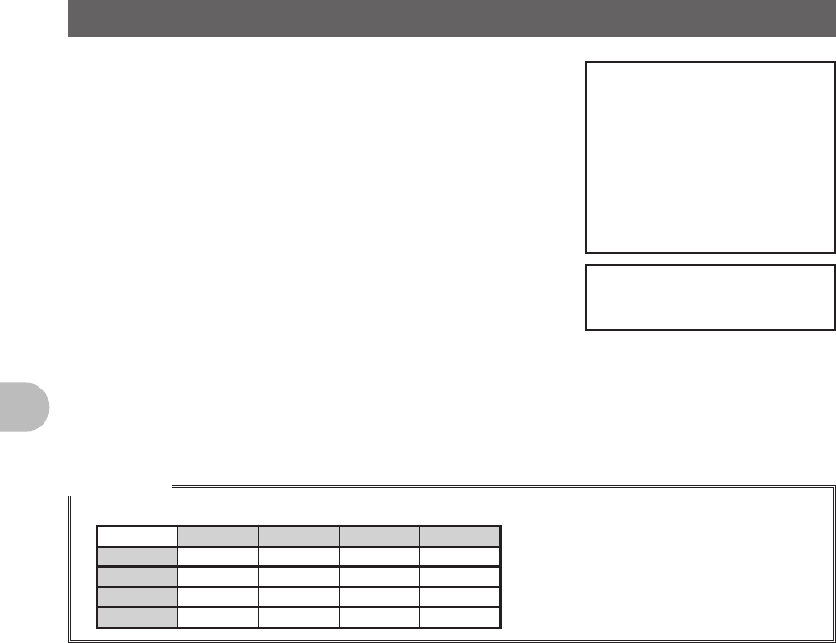
Reference
• A DTMF code is a combination of two frequencies.
1209Hz 1336Hz 1477Hz 1633Hz
697Hz 1 2 3 A
770Hz 4 5 6 B
852Hz 7 8 9 C
941Hz ½0#D
FCC ID: K6620345X40
IC: 511B-20345X40
45
Communicating with a Specific Remote Station
Communicating with a Specific Remote Station
Using the Tone Squelch Function
The tone squelch opens the squelch only when a signal containing the specified
frequency tone is received. Use of the digital code squelch (DCS) opens the squelch
only when a signal containing the specified DCS code is received. The tone squelch
function blocks monitoring of communications between other stations even when waiting
for call by a specific station for a long time.
1 Press F shortly.
The Function Menu appears.
2 Tap [SQL] to select a squelch type.
The squelch type changes in the following order each
time [SQL] is tapped:
[NOISE] → [T-TX] → [T-TRX] → [T-REV] →
[D-TRX PRGM] → [PAGER] → [JR] →[D-TX] →
[TT/DR] → [DT/TR]
The display for [SQL] changes according to the selected squelch type.
3 Press F shortly.
The squelch type is set and the screen returns to the previous one.
Reference
• The tone squelch setting or the DCS setting is also effective for scanning. If scanning is performed
with the tone squelch or the DCS function turned on, it stops only when a signal containing a tone of
the specified frequency or a signal containing the specified DCS code is received.
Display Operation
NOISE XXXXXXXXXXXXXXXXXXXXXXXXXXXXXXXXXXX.
T-TX XXXXXXXXXXXXXXXXXXXXXXXXXXXXXXXXXXX.
T-TRX XXXXXXXXXXXXXXXXXXXXXXXXXXXXXXXXXXX.
T-REV XXXXXXXXXXXXXXXXXXXXXXXXXXXXXXXXXXX.
D-TRX PRGM XXXXXXXXXXXXXXXXXXXXXXXXXXXXXXXXXXX.
PAGER
Turns on a new pager function (“PAG” appears).
When using FTM-400DR with your friends, specifying personal codes
(each code is composed of two tones) allows calling a specific station.
JR
Turns on the no-communication squelch function of the JR radio (“JR”
appears).
Mutes the 2280 MHz no-communication signal tone which is heard when
no communication is performed.
D-TX XXXXXXXXXXXXXXXXXXXXXXXXXXXXXXXXXXX.
TT/DR XXXXXXXXXXXXXXXXXXXXXXXXXXXXXXXXXXX.
DT/TR XXXXXXXXXXXXXXXXXXXXXXXXXXXXXXXXXXX.
FCC ID: K6620345X40
IC: 511B-20345X40

46
Communicating with a Specific Remote Station
Using the Tone Squelch Function
Selecting a Tone Frequency
The Tone frequency can be selected from 50 frequencies between 67.0Hz to 254.1Hz.
1 Select the operating frequency.
2 Press and hold M over 1 second.
The Setup Menu appears.
3 Tap [SIGNALING].
4 Tap [1 TONE SQL FREQ].
The tone frequency appears in orange.
5 Select a frequency with the O.
6 Press O shortly.
The tone frequency is set and it appears in green.
7 Press and hold M over 1 second.
Returns to the previous screen.
Reference
• The tone frequency set using the above-described procedure is also effective when only the tone is
sent out.
• By default, the tone frequency is set to 88.5Hz.
Searching for the Frequency of the Tone Squelch Used by the
Remote Station
The frequency of the tone squelch used by the remote station can be searched for and
displayed.
1 Press F shortly.
The Function Menu appears.
2 Tap [SQL] and select [T-TRX].
Tap until the [SQL] display switches to [T-TRX].
3 Press F shortly.
4 Tap [SQL].
Search for the tone frequency starts.
When a coincident frequency is detected, a beep is
emitted and search stops temporarily. The detected
tone frequency blinks.
Reference
• For the operation to perform when scanning stops, see “Selecting a Reception Method When
Scanning Stops” on page (See page 000).
FCC ID: K6620345X40
IC: 511B-20345X40

47
Communicating with a Specific Remote Station
Using the Tone Squelch Function
Selecting a DCS Code
You can select a DCS code from among 104 DCS codes (023 to 754).
1 Selecting the operating frequency.
2 Press and hold M over 1 second.
The Setup Menu appears.
3 Tap [SIGNALING].
4 Tap [2 DCS CODE].
The DCS code number appears in orange.
5 OSelect DCS code number with the O.
6 OPress O shortly.
The DCS code is set and DCS code number appears
in green.
7 Press and hold M over 1 second.
Returns to the previous screen.
Reference
• By default, the DCS code is set to “023”.
Searching for the Frequency of the DCS Used by the Remote
Station
The DCS code used by the remote station can be searched for and displayed.
1 Press F shortly.
The Function Menu appears.
2 Tap [SQL] and select [D-TRX].
Tap until the [SQL] display switches to [D-TRX].
3 Press F shortly.
4 Tap [SQL].
Search for the DCS code starts.
When a coincident DCS code is found, a beep is
emitted and search stops temporarily. The found DCS
code blinks.
Reference
• For the operation to perform when scanning stops, see “Selecting a Reception Method When
Scanning Stops” on page (See page 000).
FCC ID: K6620345X40
IC: 511B-20345X40

48
Communicating with a Specific Remote Station
Notification of Call from a Remote Station by the Bell
Call from a remote station (reception of a signal containing a coincident tone or DCS)
can be notified by the bell sound and the b icon blinking on on screen.
1 Press and hold M over 1 second.
The Setup Menu appears.
2 Tap [SIGNALING].
3 Tap [7 BELL RINGER].
The set value for BELL RINGER appears in orange.
4 Turn the O to select a number of times the bell
rings.
The number of times the bell rings changes in the
following order, each time O is rotated.
[OFF] → [1time] → [3times] → [5times] → [8times] →
[CONTINUE]
5 Press O shortly.
The number of times the bell rings is set and appears in green.
6 Press and hold M over 1 second.
Returns to the previous screen.
Calling Only a Specific Station New Pager Function
When using FTM-400DR with your friends, specifying personal codes (each code is
composed of two CTCSS codes) allows only a specific station to be called. Even if the
called person is not near his or her FTM-400DR, the information on the screen indicates
that he or she has been called.
Flow of Operation to Use the Pager Function
Set the same code as that of the remote station.
Determine a frequency.
Perform transmission/reception.
Confirm reception according to the information on
the screen and the bell sound
FCC ID: K6620345X40
IC: 511B-20345X40
49
Communicating with a Specific Remote Station
Calling Only a Specific Station New Pager Function
Setting the Code of Your Station
Set the “personal code (your code)” used to be called by other stations.
1 Press and hold M over 1 second.
The Setup Menu appears.
2 Tap [SIGNALING].
3 Tap [5 PAGER CODE].
The Pager Code Settings screen appears.
4 Tap [RX CODE 1].
The code number appears in orange.
5 Select code with the O.
Turn the O to select a code.
Turn the O to select the first code from among 1-50
6 Press O shortly.
The first code is set and appears in green.
7 Tap [RX CODE 2].
The code number appears in orange.
8 Turn the O to select a code.
Turn the O to select the second code from among 1-50.
9 Press O shortly.
The second code is set and appears in green.
10 Press and hold M over 1 second.
The code of your station is set and the screen returns to the previous one.
Reference • Factory Setting: [05 47]
• The first and second codes contained in your personal code may be inverted, i.e.,
“05 47” and “47 05” are recognized as being the same code.
• If the same personal code (group code) is specified for all persons, all persons can be
called at the same time.
Turning on the New Pager Function
1 Press F shortly.
The Function Menu appears.
2 Tap [SQL] and select [PAGER].
Tap until the [SQL] display switches to [PAGER].
3 Press F shortly.
4 Tap [SQL].
Now, you can “call” or “wait” a remote station using
the new pager function.
FCC ID: K6620345X40
IC: 511B-20345X40

50
Communicating with a Specific Remote Station
Calling Only a Specific Station New Pager Function
Calling a Specific Station
1 Press and hold M over 1 second.
The Setup Menu appears.
2 Tap [SIGNALING].
3 Tap [5 PAGER CODE].
The Pager Code Settings screen appears.
4 Tap [TX CODE 1].
The code number appears in orange.
5 Turn the O to select a code.
Turn the O to select the first code from among 1-50
6 Press O shortly.
The first code is set and appears in green.
7 Tap [TX CODE 2].
The code number appears in orange.
8 Turn the O to select a code.
Turn the O to select the second code from among
1-50.
9 Press O shortly.
The second code is set and appears in green.
10 Press and hold M over 1 second.
The code of remote station is set and the screen returns to the previous one.
11 Tap [SQL].
12 Press [PTT] on the microphone.
This starts calling the remote station.
FCC ID: K6620345X40
IC: 511B-20345X40

51
Communicating with a Specific Remote Station
Calling Only a Specific Station New Pager Function
Being Called by the Remote Station (Standby Operation)
If you use the new pager function at the same frequency as that of the remote station,
[PAG] displayed on the screen changes to [PIN], allowing you to check that you have
been called by the remote station.
Blinks
When called
FCC ID: K6620345X40
IC: 511B-20345X40
52
Functions Used as Needed
Functions Used as Needed
Setup Menu
Settings for the Setup Menu
The Setup Menu is a menu for selecting and setting various functions from a list for
convenient use.
●Resetting the settings for the Setup Menu
Settings for the Setup Menu can be reset to Factory Settings through the following
operation:
1 Press and hold M over 1 second.
The Setup Menu appears.
2 Tap [RESET/CLONE].
3 Tap [1 FACTORY RESET].
4 Tap [OK?].
Tapping [Cancel] cancels resetting.
5 The FTM-400DR reboots.
Setting content are reset and the FTM-400DR turns
off once.
Shortly afterwards, the FTM-400DR automatically
restarts.
Setup Menu Operations List
Set Mode Number / Items Function Description Selectable Items
(Bold Letter are Factory Setting Values)
DISPLAY
1 DISPLAY SELECT Screen display setting
for when M is pressed
shortly.
NAVIGATION: ON / OFF
TIMER/CLOCK: ON / OFF
ALTITUDE: ON / OFF
GPS INFORMATION: ON / OFF
2 BACKGROUND
COLOR
Setting for screen
background color.
GREEN / BLUE / ORANGE /
PURPLE / GRAY
3 BAND SCOPE Setting for screen
display when SCOPE is
executed.
Setting for frequency
bandwidth
NARROW / WIDE
4 LCD BRIGHTNESS Setting for LCD
brightness
MIN / 2 / 3 / 4 / 5 / 6 / MAX
5 LCD CONTRAST Setting for LCD contrast –3 / –2 / –1 / 0 / +1 / +2 / +3
6 TIME/VDD Setting for display
content (Time/Voltage)
TIME / VDD
TX/RX
1 MODE Reception mode
switching
AUTO / FM / NARROW FM / AM
DIGITAL
1 DIGITAL MODE VOICE & DATA / FULL RATE (T.B.D.)
FCC ID: K6620345X40
IC: 511B-20345X40
53
Functions Used as Needed
Setup Menu
Set Mode Number / Items Function Description Selectable Items
(Bold Letter are Factory Setting Values)
TX/RX
DIGITAL
2 SQL TYPE OFF / CODE / BREAK
3 SQL CODE CODE: 001 to 126
4 PROFILE SEL DIGTAL / APRS / GSMS
5PROFILE (DIGITAL)PROFILE: XXXXXXXXXX
6 DISTINATION MODE CQ / CALLSIGN / GROUP
7 DISTINATION CALL 10 characters for each CALL1 to CALL8
8 POSITION DATA
(VOICE)
ON / OFF
9 POSITION DATA
(ONLY)
ON / OFF
AUDIO
1 MIX/SEPARATE Setting for Reception
Audio
MIX / SEPARATE
2 SUB BAND MUTE Setting for Sub Band
Mute
OFF / ON
(Mutes SUB BAND for both transmission
and reception)
3 MIC GAIN Adjustment for
microphone Input
MIN / LOW / NORMAL / HIGH / MAX
MEMORY
1 MEMORY CH DISPLAY Setting for memory
channel display
ALL / INBAND
(ALL: Displays all memory channels
INBAND: Only displays memory channels
within BAND)
2 ALPHA TAG SIZE Setting for the display
size of memory channel
tag
SMALL / LARGE
3 MEM EDIT Transitions to Memory
Editor screen
4 MEM SCAN TYPE Memory channel setting
for when memory is
scanned
ALL MEM / SELECT MEM
SIGNALING
1 TONE SQL FREQ Setting for tone
frequency
67Hz to 254.1Hz
Default 88.5Hz
2 DCS CODE Setting for DCS Code 023 to 754
3 AUTO DIALER Setting for automatic
transmission of DTMF
Code
OFF / ON
4 DTMF MEMORY Registration of DTMF
Code
1 to 9 channels 16 characters each
5 PAGER CODE Setting for pager
individual code
RX CODE1 (05), CODE (47)
TX CODE1 (05), CODE2 (47)
6PRG REV TONE 300Hz to 3000Hz
7 BELL RINGER Output setting for the
Bell Function
OFF / 1time / 3times / 5times / 8times /
CONTINUOUS
FCC ID: K6620345X40
IC: 511B-20345X40
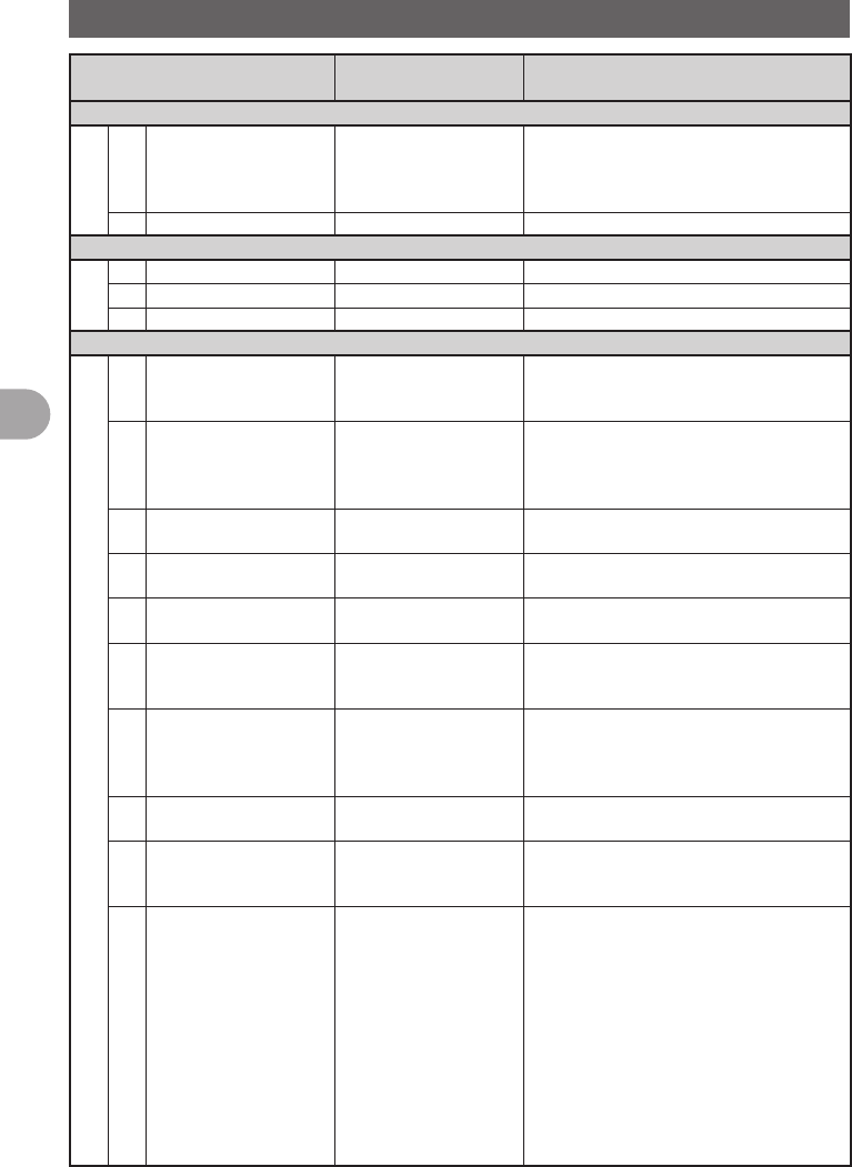
54
Functions Used as Needed
Setup Menu
Set Mode Number / Items Function Description Selectable Items
(Bold Letter are Factory Setting Values)
SIGNALING
8 SQL EXPANTION Setting for separate
Squelch Type in
transmission and
reception.
OFF / ON
9 WX ALERT OFF / ON For USA models only
WiRES X
1 DUAL WATCH STOP AUTO / HOLD
2 SCAN DIRECTION UP / DOWN
3 SCAN RESUME BUSY / HOLD / 1sec / 3 sec / 5sec
CONFIG
1 DATE & TIME ADJ Setting for the internal
clock function of the
FTM-400DR
Date 'xx-xx-xx (xxx)
Time xx: xx
2 DATE & TIME FORMAT Setting for display
format of the internal
clock function
DATE: yyyy/mm/dd /
yyyy/dd/mm / mm/dd/yyyy /
dd/mm/yyyy
TIME: 24 hour / 12 hour
3 TIME ZONE Setting for Time Zone UTC±13h (0.5h Step)
UTC+9:00 TOKYO
4 AUTO RPT SHIFT Setting for automatic
repeater shift
OFF / ON
5 RPT SHIFT Setting for repeater shift
direction
OFF / – / +
6 RPT SHIFT FREQ Setting for repeater shift
width
0.00 - 99.95MHz
This default setting is based on Band
specification(50KHz step).
7 FM AM STEP Setting for channel step AUTO / 5.00KHz / 6.25KHz /
8.33KHz / 9.00KHz / 10.00KHz / 12.50KHz /
15.00KHz / 20.00KHz / 25.00KHz /
50.00KHz / 100.00KHz / 200.00KHz
8 BEEP Setting for beep sound
output
OFF / LOW / HIGH
9 CLOCK TYPE Setting for clock shift A / B
A: Clock shift operation AUTO
B: Clock Clock shift operation forced ON
10 MIC PRG KEY Setting for P button on
microphone
P1: OFF / BAND SCOPE / SCAN / HOME /
DCS CODE / TONE FREQ / RPT SHIFT /
REVERSE / TX POWER /
SQL OFF / T-CALL (CE) / VOICE /
WiRES / PRG FREQ or WX / S.LIST /
MSG / REPLY / M.EDIT
P2: OFF / BAND SCOPE / SCAN / HOME /
DCS CODE / TONE FREQ /
RPT SHIFT / REVERSE /
TX POWER / SQL OFF / T-CALL /
VOICE / WiRES / PRG FREQ or WX /
S.LIST / MSG / REPLY / M.EDIT
FCC ID: K6620345X40
IC: 511B-20345X40
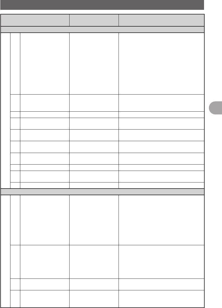
55
Functions Used as Needed
Setup Menu
Set Mode Number / Items Function Description Selectable Items
(Bold Letter are Factory Setting Values)
CONFIG
10 MIC PRG KEY Setting for P button on
microphone
P3: OFF / BAND SCOPE / SCAN / HOME /
DCS CODE / TONE FREQ /
RPT SHIFT / REVERSE / TX POWER /
SQL OFF / T-CALL / VOICE / WiRES /
PR FREQ or WX / S.LIST / MSG /
REPLY / M.EDIT
P4: OFF / BAND SCOPE / SCAN / HOME /
DCS CODE / TONE FREQ / RPT SHIFT /
REVERSE / TX POWER / SQL OFF /
T-CALL / VOICE / WiRES / PRG FREQ
or WX / S.LIST / MSG / REPLY / M.EDIT
11 RX COVERRAGE Setting for bandwidth
during Scope operation
NORMAL / WIDE
(NORMAL: Displays Ham Band only
WIDE: Displays all bands)
12 UNIT METRIC / INCH
13 APO Setting for APO
operation time
OFF / 0.5 hour to 12.0 hour
(0.5 hour Step)
14 TOT Setting for Time Out
timer
OFF / 5min to 30min (5min Step)
depending on specification
15 BLUETOOTH PAIRING Setting for DIAL
operation of PIN Code
BLUETOOTH PAIRING: Select PIN Code
with DIAL operation
16 GPS DATUM Select a datum used for
GPS Function
WGS-84 / TOKYO MEAN
17 GPS DEVICE INTERNAL / EXTERNAL
18 GPS LOG Setting for access time
to GPS
ON / OFF
1 / 2 / 5 / 10 / 30 / 60 seconds
19 .X-BAND REPEATER Execute .X-BAND REPEATER
DATA
1 COM PORT SETTING Setting for COM PORT SPEED: 4800 / 9600 / 19200bps
OUTPUT: OFF (camera) /
GPS OUT / PACKET OUT / WAYPOINT
INPUT: OFF / WP
FORMAT: NMEA6 / NMEA7 / NMEA8 /
NMEA9
WP FILTER: ALL / MOBILE / FREQ /
OBJ/ITEM / DIGI / VOIP / WEATHER /
YAESU / C RINGER / R RINGER
2 DATA BAND SELECT Setting for band
selection of APRS/DATA
APRS: MAIN BAND / SUB BAND /
A-BAND FIX / B-BAND FIX /
A=TX/R=RX / A=RX/R=TX
DATA: MAIN BAND / SUB BAND / A-BAND
FIX / B-BAND FIX / A=TX/R=RX /
A=RX/R=TX
3 DATA SPEED Setting for APRS/DATA
transmission port rate
APRS: 1200 bps / 9600 bps
DATA: 1200 bps / 9600 bps
4 DATA SQUELCH Setting for digital
repeater route
APRS: RX BAND / TX/RX BAND
DATA: RX BAND / TX/RX BAND
TX: ON / OFF
FCC ID: K6620345X40
IC: 511B-20345X40

56
Functions Used as Needed
Setup Menu
Set Mode Number / Items Function Description Selectable Items
(Bold Letter are Factory Setting Values)
APRS
1 APRS COMPASS Operation Setting for
APRS compass
NORTH UP / HEADING UP
2 APRS DISTINATION Display of Model Code APY100 (Fixed)
3 APRS FILTER Setting for filter function Mic-E: ON / OFF
POSITION: ON / OFF
WEATHER: ON / OFF
OBJECT: ON / OFF
ITEM: ON / OFF
STATUS: ON / OFF
OTHER: ON / OFF
RANGE LIMIT: ON / OFF
ALTNET: ON / OFF
4 APRS MODEM Setting for APRS port
rate
OFF / ON
5 APRS MUTE ON/OFF setting for B
Band AF Mute when
setting the APRS
OFF / ON
6 APRS POP-UP Setting for Beacon type
to display as Pop-Up
BEACON: OFF / 3 sec / 5 sec /
10 sec / HOLD
MYPACKET: OFF / ON
7 APRS POP-UP COLOR Setting for background
color of beacon that
appears on Pop-up.
BEACON: OFF / LCD COLOR /
WHITE-BLUE / SKY-BLUE /
MARINE-BLUE / GREEN /
YELLOW-GREEN / ORANGE /
AMBER / WHITE
MOBILE: OFF / LCD COLOR /
WHITE-BLUE / SKY-BLUE /
MARINE-BLUE / GREEN /
YELLOW-GREEN / ORANGE /
AMBER / WHITE
OBJ/ITEM: OFF / LCD COLOR /
WHITE-BLUE / SKY-BLUE /
MARINE-BLUE / GREEN /
YELLOW-GREEN / ORANGE /
AMBER / WHITE
CAL RING: OFF / LCD COLOR /
WHITE-BLUE / SKY-BLUE /
MARINE-BLUE / GREEN /
YELLOW-GREEN / ORANGE /
AMBER / WHITE
RNG RING: OFF / LCD COLOR /
WHITE-BLUE / SKY-BLUE /
MARINE-BLUE / GREEN /
YELLOW-GREEN / ORANGE /
AMBER / WHITE
MY PACKET: OFF / LCD COLOR /
WHITE-BLUE / SKY-BLUE /
MARINE-BLUE / GREEN /
YELLOW-GREEN / ORANGE /
AMBER / WHITE
FCC ID: K6620345X40
IC: 511B-20345X40
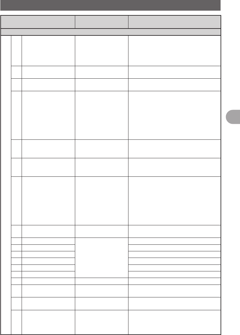
57
Functions Used as Needed
Setup Menu
Set Mode Number / Items Function Description Selectable Items
(Bold Letter are Factory Setting Values)
APRS
8 APRS RINGER Setting for bell sound
for when there is a
incoming beacon.
TX BEACON: ON / OFF
RX BEACON: ON / OFF
MY PACKET: ON / OFF
CALL RINGER: ON / OFF
RNG RINGER: 1-100 / OFF
9 APRS RINGER (CALL) Call Sign setting for
CALL RINGER
1 to 8 stations
10 APRS TXDELAY Setting for the data
delivery delay time
100ms / 150ms / 200ms / 250ms / 300ms /
400ms / 500ms / 750ms / 1000ms
11 APRS UNITS Unit setting for APRS
display
POSITION: mm/ss
DISTANCE: km / mile
SPEED: km/h / knot / mph
ALTITUDE: m / ft
BARO: hPa/mb/mmHg/inHg
TEMP: ˚C / F
RAIN: mm / inch
WIND: m/s / mph / knot
12 BEACON INF SELECT Setting for transmission
beacon information
AMBIGUITY: OFF / 1-4digit
SPD/CSE: ON / OFF
ALTITUDE: ON / OFF
13 BEACON STATUS TXT Input setting for Status
Text
SELECT: TEXT1-5 / OFF
TX RATE: 1/1-1/8 1/2 (FREQ) -
1/8(FREQ), TEXT1-TEXT5
14 BEACON TX Switching between
automatic and manual
transmission of beacon
AUTO: OFF / ON / SMART
INTERVAL: 30sec-60min
Default 5min
PROPORTIONAL: ON / OFF
DECAY: ON / OFF
LOW SPEED: 1-99 (5km/h or 3mph)
RATE LIMIT: 5-180sec
Default 30sec
15 DIGI PATH SELECT Setting for digital
repeater route
OFF / WIDE1-1 / WIDE1-1.WIDE2-1 /
PATH1-PATH4 / FULL1 / FULL2
16 DIGI PATH 1 Address setting for
digital repeater route
ADDR1: ADDR2: No Input
17 DIGI PATH 2 ADDR1: ADDR2: No Input
18 DIGI PATH 3 ADDR1: ADDR2: No Input
19 DIGI PATH 4 ADDR1: ADDR2: No Input
20 DIGI PATH FULL 1 ADDR1: -ADDR8: No Input
21 DIGI PATH FULL 2 ADDR1: -ADDR8: No Input
22 PROFILE xxxxxx-xx
23 MY POSITION SET Position setting of your
station
GPS / MANUAL /
POINT MEM GR1-1to GR4-4
24 MY POSITION Manual position setting
of your station
Latitude: x xx°xx' xx"
Longitude: x xxx°xx' xx"
25 MY SYMBOL Setting for the symbol of
your station
ICON1:[/>] Car /
ICON2: [/R] REC.Vehicle /
ICON3: [/-] House QTH (VHF) /
USER: [YY] Yaesu Radios
FCC ID: K6620345X40
IC: 511B-20345X40

58
Functions Used as Needed
Setup Menu
Set Mode Number / Items Function Description Selectable Items
(Bold Letter are Factory Setting Values)
APRS
26 POSITION COMMENT Setting for position
comments
Off Duty / En Route / In Service /
Returnings / Committed / Special /
Priority / Custom 0 to 6 / Emergency!
27 SmartBeaconing Setting for Smart
Beaconing
STATUS: OFF / TYPE1 / TYPE2 / TYPE3
LOW SPEED: 2-30 Default 5
HIGH SPEED: 3-70 Default 70
SLOW RATE: 1-100min Default 30min
FAST RATE: 10-180 Default 120sec
TURN ANGLE: 5-90° Default 28°
TURN SLOPE: 1-255 Default 26
TURN TIME: 5-180sec Default 30sec
28 SORT FILTER Setting for Sort Function
and Filter Function
SORT: TIME / CALLSIGN / DISTANCE
FILTER: ALL / MOBILE /
FREQUENCY / OBJ/ITEM /
DIGIPEATER / VOIP / WEATHER /
YAESU / OTHER PKT /
CALL RINGER / RNG RINGER /
1200bps / 9600bps
29 VOICE ALERT Setting for Voice Alert
Function
V.ALERT: NORMAL / TONE SQL / DCS /
RX-TSQL / RX-DCS
TSQL: 67.0Hz ~ 254.1Hz
(Default 100.0Hz)
DCS: DCS023 ~ DCS754
(Default DCS023)
OPTION
1 BLUETOOTH Setting for BLUETOOTH
headset.
AUDIO: AUTO / FIX
MODE: MIX / SEPARATE
BATTERY: NORMAL / SAVE
VOX: ON /OFF
GAIN: HIGH / LOW
2 VOICE MEMORY Setting for Voice
Memory Function
PLAY/REC: FREE 5min / LAST30sec
ANNOUNCE: AUTO / MANUAL
LANGUAGE: JAPANESE / ENGLISH
VOLUME: HIGH / MID / LOW
SD
1 BACK UP Write to SD / Read from SD /
FORMAT: To selection screen
2 GROUP ID Write to SD / Read from SD /
FORMAT: To selection screen
RESET/CLONE
1 FACTORY RESET Reset all settings to
Factory Settings
Resets all settings to Factory Settings
(Was ALL RESET in past models). To
confirmation screen.
2 PRESET Registers Preset screen Registration of Preset screen
OK? / Cancel?
3 RECALL PRESET Recalls Preset screen Recall Preset screen
OK? or Cancel?, after selecting from a list.
FCC ID: K6620345X40
IC: 511B-20345X40
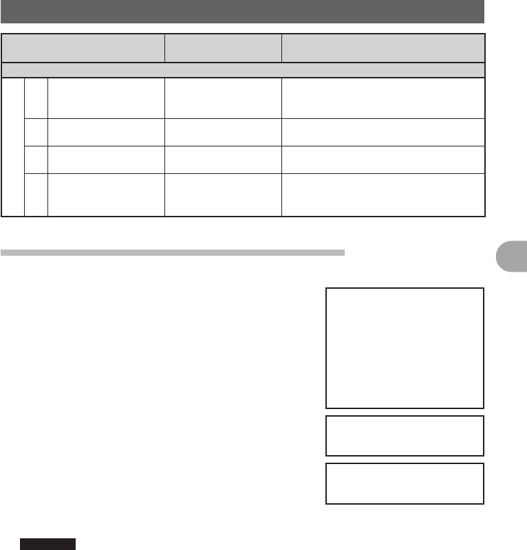
59
Functions Used as Needed
Setup Menu
Set Mode Number / Items Function Description Selectable Items
(Bold Letter are Factory Setting Values)
RESET/CLONE
4 MEM CH RESET Erases memory
channels
ALL MEM CH CLEAR: Only erases
memory channels and keeps MENU
content. To confirmation screen.
5 MEM CH SORT Sorts memory channels. Sort A/B band memory channels.
To confirmation screen.
6 APRS RESET Resets APRS settings. Reset APRS settings.
To confirmation screen.
7 CLONE Copies the setting
content of your radio to
other.
This radio → other (TX) /
This radio ← other (RX)
To selection screen
Apply settings to contents displayed on screen.
Setting content displayed on screen when M is pressed shortly.
1 Press and hold M over 1 second.
The Setup Menu appears.
2 Tap [DISPLAY].
3 Tap [1 DISPLAY SELECT].
The display settings for the screen appears.
4 Tap an item to display.
Select the screen to display from [NAVIGATION]
[TIMER/CLOCK] [ALTITUDE] [GPS INFOR].
Tapping an item switches between [ON] and [OFF].
5 Set other screens.
Repeat Step 4 to set other screens.
6 Press and hold M over 1 second.
The displayed screen is set and the screen returns to
the previous one.
Reference • Factory Settings: All screens are set to [OFF].
FCC ID: K6620345X40
IC: 511B-20345X40

60
Functions Used as Needed
Setup Menu
Setting the Background Color of the Screen
The background color for the screen can be selected from the following 5 colors:
• Green • Blue • Orange • Purple • Grey
1 Press and hold M over 1 second.
The Setup Menu appears.
2 Tap [DISPLAY].
3 Tap [2 BACKGROUND COLOR] and select a
background color.
The background color changes in the following order
each time [2 BACKGROUND COLOR] is tapped.
[GREEN] → [BLUE] → [ORANGE] → [PURPLE] →
[GRAY]
4 Press and hold M over 1 second.
The background color is set and the screen returns to
the previous one.
Reference • Factory Settings: All screens are set to [GREEN].
Setting the Frequency Width for Band Scope
The frequency band width to be displayed when Band Scope is operated can be set.
1 Press and hold M over 1 second.
The Setup Menu appears.
2 Tap [DISPLAY].
3 Tap [3 BAND SCOPE] and select frequency band
width.
Frequency band width switches between [NARROW]
and [WIDE] each time [3 BAND SCOPE] is tapped.
NARROW: Frequency band width appears in a narrow
search width.
WIDE: Frequency band width appears in a wide
search width.
4 Press and hold M over 1 second.
The frequency band width is set and the screen returns to the previous one.
Reference • Factory Setting: [NARROW]
FCC ID: K6620345X40
IC: 511B-20345X40
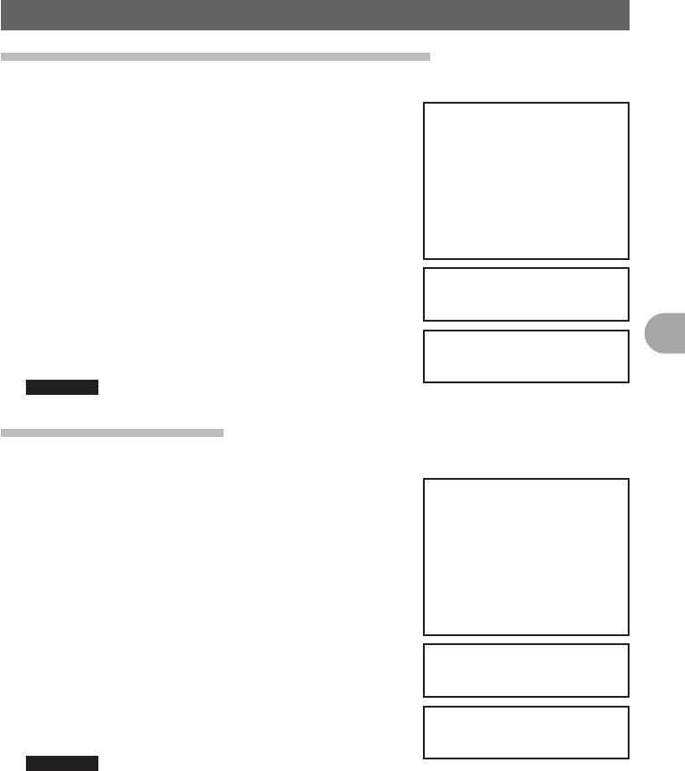
61
Functions Used as Needed
Setup Menu
Adjusting the LCD Backlight Brightness Level
The brightness level of the LCD backlight can be adjusted.
1 Press and hold M over 1 second.
The Setup Menu appears.
2 Tap [DISPLAY].
3 Tap [4 LCD BRICHTNESS].
The LCD Brightness Setting screen appears.
4 Tap [–] or [+] to adjust brightness.
Select the brightness from [MIN], [2], [3], [4], [5], [6],
and [MAX].
The selected brightness can be confirmed on screen.
5 Press and hold M over 1 second.
The LCD Brightness is set and the screen returns to
the previous one.
Reference • Factory Setting: [MAX]
Adjusting LCD Contrast
The contrast level of the screen can be adjusted.
1 Press and hold M over 1 second.
The Setup Menu appears.
2 Tap [DISPLAY].
3 Tap [5 LCD CONTRAST].
The LCD Contrast Setting screen appears.
4 Tap [–] or [+] to adjust contrast.
Select the contrast from [–3], [–2], [–1], [0], [+1], [+2],
and [+3].
The selected contrast can be confirmed on screen.
5 Press and hold M over 1 second.
The LCD contrast level is set the screen returns to the
previous one.
Reference • Factory Setting: [0]
FCC ID: K6620345X40
IC: 511B-20345X40

62
Functions Used as Needed
Setup Menu
Switching between Time and Voltage display
The display on the top right of the screen can be switched between [Time Display] and
[Voltage Display].
1 Press and hold M over 1 second.
The Setup Menu appears.
2 Tap [DISPLAY].
3 Tap [6 TIME/VDD] and select the display content.
The display switchws between [TIME] and [VDD]
every time [6 TIME/VDD].
TIME: The Time appears.
VDD: The voltage appears.
4 Press and hold M over 1 second.
The display content is set and the screen returns to
the precious one.
Reference • Factory Setting: [TIME]
Adjusting volume respectively to A/B Bands.
The volume for A Band and B Band can be separately adjusted. Additionally, if your
radio is connected to external speakers, the A/B Band Audio can be separated to left
and right speakers.
1 Press and hold M over 1 second.
The Setup Menu appears.
2 Tap [TX/RX].
3 Tap [AUDIO].
4 Tap [1 MIX/ SEPERATE] and select ½½½.
Audio is switched between [MIX] and [SEPERATE]
each time [1 MIX/SEPERATE] is tapped.
MIX: Simultaneously adjust volume for A Band and B
Band.
SEPERATE: Separately adjust volume for A Band and
B Band.
5 Press and hold M over 1 second.
The selected volume adjustment is set and the screen
returns to the previous one.
Reference • Factory Setting: [MIX]
FCC ID: K6620345X40
IC: 511B-20345X40
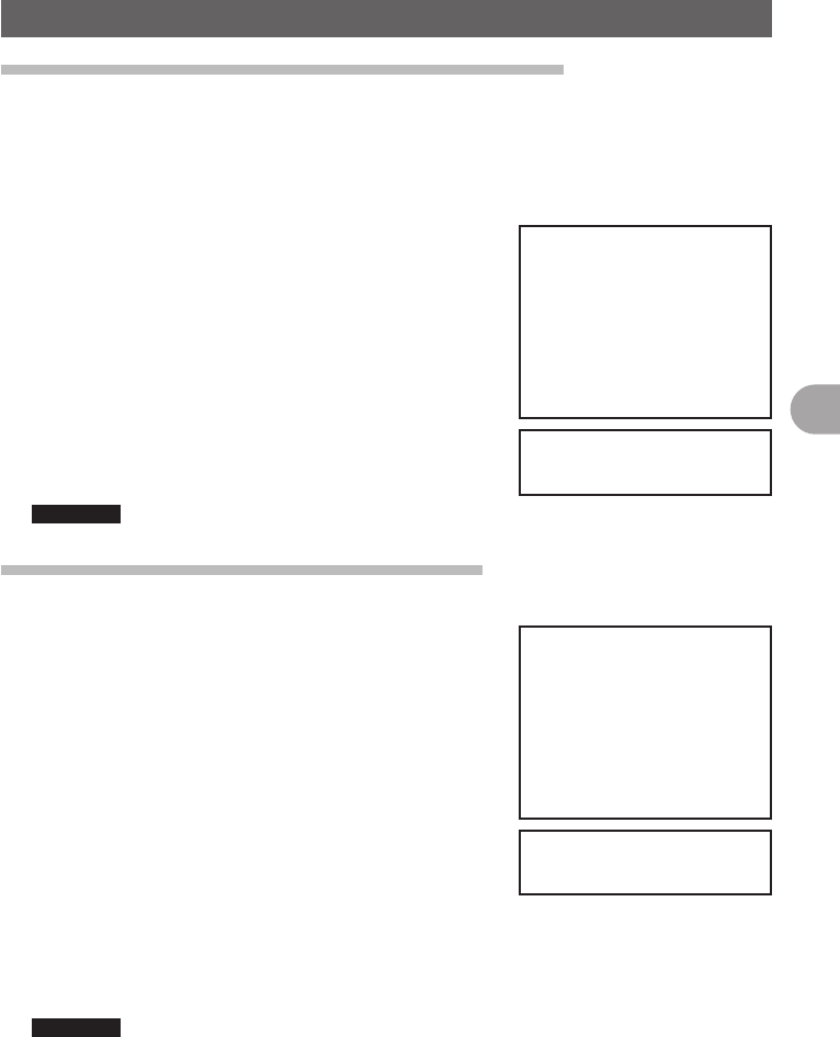
63
Functions Used as Needed
Setup Menu
Setting the Display Method for Memory Channels
The display method for registered memory channels can be selected from the following
2 methods:
• ALL: Displays all registered memory channels
• INBAND: Only displays memory channels within the band currently in use.
1 Press and hold M over 1 second.
The Setup Menu appears.
2 Tap [MEMORY].
3 Tap [1 MEMORY CH DISPLAY] and set the memory
channels to display.
Tapping [1 MEMORY CH DISPLAY] will switch
between [ALL] and [INBAND].
4 Press and hold M over 1 second.
The display method for memory channels is set and
the screen returns to the previous one.
Reference • Factory Setting: [ALL]
Setting the Squelch Type for transmission
Preset squelch types can be used separately for transmission and reception.
1 Press and hold M over 1 second.
The Setup Menu appears.
2 Tap [SIGNALING].
3 Tap [8 SQL EXPANSION] and select between OFF/
ON.
Tapping [8 SQL EXPANSION] switches between [ON]
and [OFF].
OFF: Use the same squelch type for transmission and
reception.
ON: Use separate squelch type for transmission and
reception.
4 Press and hold M over 1 second.
The squelch type for transmission and reception is set and the screen returns to the
previous one.
Reference • Factory Setting: [OFF]
FCC ID: K6620345X40
IC: 511B-20345X40

64
Functions Used as Needed
Setup Menu
Setting the display format for the Clock Function
The display format for the internal clock can be chosen from the following types:
• Date Display: Month/Day/Year, Year/Month/Day, Day/Month/Year, Year/Day/Month
• Time Display: 24 Hour Display, 12 Hour Display
1 Press and hold M over 1 second.
The Setup Menu appears.
2 Tap [CONFIG].
3 Tap [2 DATA & TIME FORMAT].
The setting screen for date and time display appears.
4 Tap [DATE].
The setting screen for date display format appears.
5 Tap format to be displayed.
Select the display format for the Date.
mmm/dd/yyyy: Date appears as Month/Day/Year
yyy/mmm/dd: Date appears as Year/Month/Day
dd/mmm/yyyy: Date appears as Day/Month/Year
yyy/dd/mmm: Date appears as Year/Day/Month
6 Tap [BACK].
7 Tap [TIME] and select the display format for time.
Tapping [TIME] switches between [24 hour] and [12
hour].
8 Press and hold M over 1 second.
The Time and Date display format is set and the
screen returns to the previous one.
Reference • Factory Setting: Date Display Format mm/dd/yyyy,
Date Display Format 24 hour
FCC ID: K6620345X40
IC: 511B-20345X40
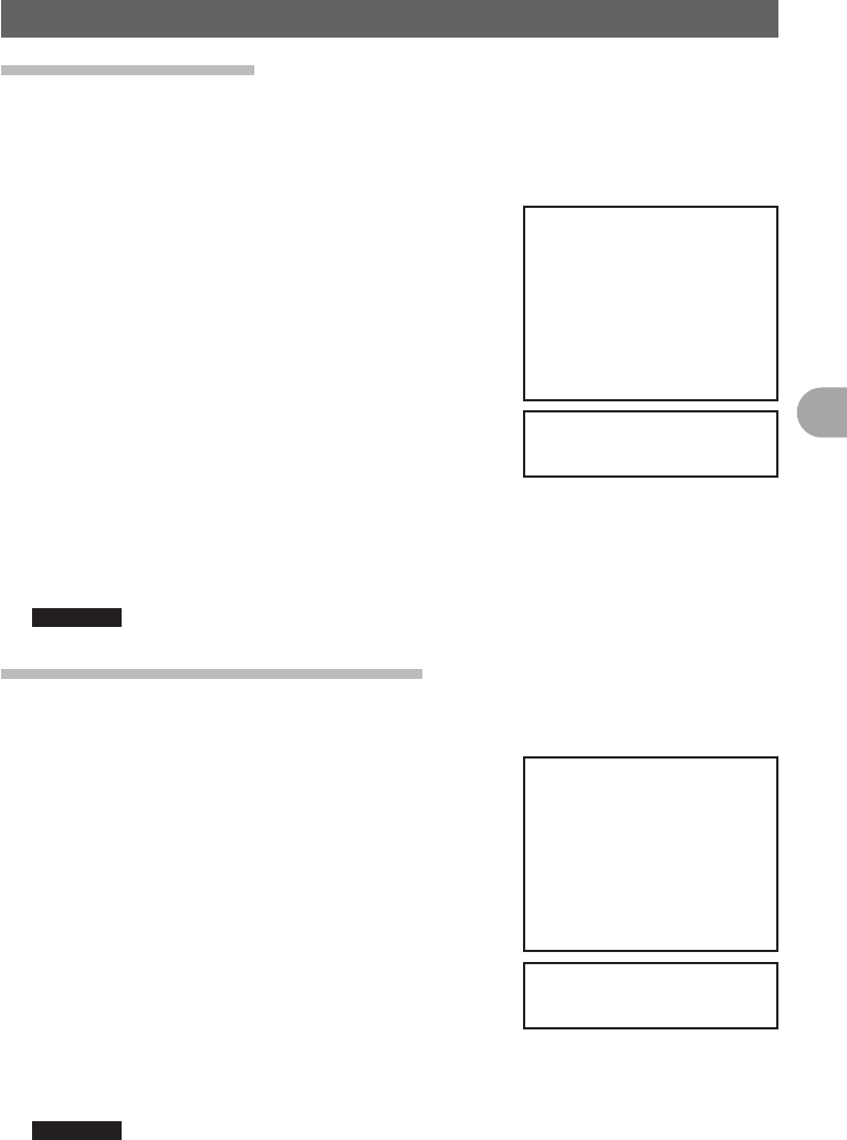
65
Functions Used as Needed
Setup Menu
Setting the Time Zone
The internal clock can be set to time data from GPS (Coordinated Universal Time). On
Factory Settings the internal clock is set to Japan Time (UTC+9:00 TOKYO) and does
not need to be adjusted.
The time zone can be adjusted in 0.5 hour units for up to ±13 hours.
1 Press and hold M over 1 second.
The Setup Menu appears.
2 Tap [CONFIG].
3 Tap [3 TIME ZONE].
The time zone appears in orange.
4 Turn the O to adjust the time zone.
Rotate the O and select the desired time zone for a
oversea city.
The time zone can be adjusted in 0.5 hour units for up
to ±13 hours.
5 Press O shortly.
The time zone is set and displayed in green.
6 Press and hold M over 1 second.
Returns to the previous screen.
Reference • Factory Setting: UTC+9:00 TOKYO
Setting the Automatic Repeater Shift
When using the repeater for communication, the automatic repeater shift function that
automatically starts communication via the repeater can be set to ON/OFF.
1 Press and hold M over 1 second.
The Setup Menu appears.
2 Tap [CONFIG].
3 Tap [4 AUTO RPT SHIFT] and select between ON/
OFF.
Tapping [4 AUTO RPT SHIFT] switches between [ON]
and [OFF].
ON: Automatically starts communication using
repeater shift.
OFF: Manually select tone frequency and start
communication
4 Press and hold M over 1 second.
The automatic repeater shift is set and the screen returns to the previous one.
Reference • Factory Setting: ON
FCC ID: K6620345X40
IC: 511B-20345X40

66
Functions Used as Needed
Setup Menu
Setting the Clock Shift of the Microcomputer
You can set microcomputer clock signal so as not to receive as internal spurious by high
frequency. Select [A] for normal time usage.
1 Press and hold M over 1 second.
The Setup Menu appears.
2 Tap [CONFIG].
3 Tap [9 CLOCK TYPE] and set A/B.
Tapping [9 CLOCK TYPE] switches between [A] and
[B].
A: The clock shift function automatically switches
between ON and OFF.
B: The clock shift function is active at all times.
4 Press and hold M over 1 second.
The clock type is set and the screen returns to the previous one.
Reference • Factory Setting: A
Setting the Program Keys on the Microphone
Assign functions to the program keys (P1 to P4) on the accessory microphone (MH-48).
1 Press and hold M over 1 second.
The Setup Menu appears.
2 Tap [CONFIG].
3 Tap [10 MIC PRG KEY].
The Microphone Program Keys setting screen
appears.
4 Tap the Program key you would like to set.
Tap the Program Key (P1 to P4) you would like to
assign a function.
The functions that can be assigned are displayed.
If the function you would like to assign is not
displayed, scroll the screen with [▲] and [▼].
5 Tap the function you would like to assign.
The function to assign to the program key is selected.
6 Tap [BACK].
The screen returns to the program key (P1 to P4)
selection.
7 Set functions for the other program keys.
Repeat steps 4 to 6 and assign functions to other function keys.
8 Press and hold M over 1 second.
The function is assigned to the program key and returns to the previous screen.
Reference • Factory Setting: P1: SQL OFF P2: HOME P3: RPT SHIFT P4: TX POWER
FCC ID: K6620345X40
IC: 511B-20345X40
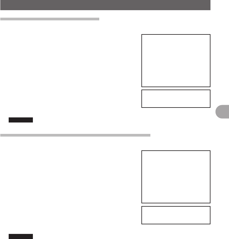
67
Functions Used as Needed
Setup Menu
Setting the Bandwidth to Scope
The Bandwidth for when scoping in VFO mode or Memory mode can be set.
1 Press and hold M over 1 second.
The Setup Menu appears.
2 Tap [CONFIG].
3 Tap [11 RX COVERAGE] to select NORMAL/WIDE.
Tapping [11 RX COVERAGE] switches between
[NORMAL] and [WIDE].
NORMAL: Scopes Ham Band only.
WIDE: Scopes all Bands.
4 Press and hold M over 1 second.
The bandwidth to scope is set and the screen returns
to the previous one.
Reference • Factory Setting: NORMAL
Setting the unit of measurement to be displayed
The unit of measurement can be set for displaying altitude, distance, and speed.
1 Press and hold M over 1 second.
The Setup Menu appears.
2 Tap [CONFIG].
3 Tap [12 UNIT] and select METRIC/INCH.
Tapping [12 UNIT] switches between [METRIC] and
[INCH].
METRIC: The unit of measurement appears in metric.
INCH: The unit of measurement appears in inch.
4 Press and hold M over 1 second.
The unit of measurement is set and the screen returns
to the previous one.
Reference • Factory Setting: METRIC
FCC ID: K6620345X40
IC: 511B-20345X40

68
Functions Used as Needed
Setup Menu
Automatically Turning Off the Power APO Function
The FTM-400DR can be set so that it turns off automatically if you do not operate it for
a certain period of time. You can change the time until the FTM-400DR is turned off
automatically Use this function after setting the clock, referring to [Setting the Clock
(See page 21)].
1 Press and hold M over 1 second.
The Setup Menu appears.
2 Tap [CONFIG].
3 Tap [13 APO].
The APO setting screen appears.
4 Tap [–] or [+] to adjust the time.
Specify the time until the FTM-400DR is turned off
automatically in steps of 30 minutes.
OFF / 30 min / 1 hour to 12 hours
5 Press and hold M over 1 second.
The Auto Power Off function is set and the screen returns to the previous one.
Reference • Factory Setting: OFF
Restricting the Continuous Transmission Time TOT Function
The FTM-400DR can be set that it automatically returns to reception state after
performing continuous transmission for a certain period of time. Accidental transmission
of unnecessary radio waves and unwanted battery power consumption can be
prevented (time-out timer function).
1 Press and hold M over 1 second.
The Setup Menu appears.
2 Tap [CONFIG].
3 Tap [14 TOT].
The time display for TOT appears in orange.
4 Turn the O to set the time.
Turn the O to set the Time Out time in steps of 5
minutes.
OFF / 5 min to 30 min
5 Press O shortly.
The time is set and displayed in green.
6 Press and hold M over 1 second.
Returns to the previous screen.
Reference • Factory Setting: 5 min
FCC ID: K6620345X40
IC: 511B-20345X40
69
Functions Used as Needed
Setup Menu
Setting PIN Code for a BLUETOOTH headset
Using a BLUETOOTH headset requires setting its PIN code to the FTM-400DR.
Reference
• The PIN code for a BLUETOOTH headset from our company is 6111. If the BLUETOOTH headset
is not from our company, check the PIN code by refereeing to the instruction manual for that
product.
1 Press and hold M over 1 second.
The Setup Menu appears.
2 Tap [CONFIG].
3 Tap [15 BLUETOOTH PAIRING].
PIN code input screen appears
4 Tap the numeric keys to input the PIN code.
By tapping the numbers displayed on screen, input
the 4 digit code.
Reference • Tap [Cancel] if incorrect number is entered.
5 Tap [ENT].
The PIN code is set.
6 Press and hold M over 1 second.
Returns to the previous screen.
Reference • Factory Setting: 6111
Selecting Datum for GPS function.
Select a datum used for the GPS function.
1 Press and hold M over 1 second.
The Setup Menu appears.
2 Tap [CONFIG].
3 Tap [16 GPS DATUM] to set a datum.
Tapping [16 GPS DATUM] switches between [TOKYO
MEAN] and [WGS 84].
WGS-84: The standard setting for worldwide
standard. Select WGS-84 under normal
operation.
TOKYO MEAN: Enables reducing the error in
positioning when using GPS in Japan
(Tokyo)
4 Press and hold M over 1 second.
The datum for GPS is set and the screen returns to the previous one.
FCC ID: K6620345X40
IC: 511B-20345X40

70
Functions Used as Needed
Setup Menu
Setting the GPS Device to Use
Before using the GPS function, select whether to use the internal GPS function of the
FTM-400DR or a connected external GPS device.
1 Press and hold M over 1 second.
The Setup Menu appears.
2 Tap [CONFIG].
3 Tap [17 GPS DEVICE] and set the GPS device.
Tapping [17 GPS DEVICE] switches between
[INTERNAL] and [EXTERNAL].
INTERNAL: Use the internal GPS function of the
FTM-400DR.
EXTERNAL: Use the connected external GPS device.
4 Press and hold M over 1 second.
The GPS function (or device) is set and the screen
returns to the previous one.
Reference • Factory Setting: INTERNAL
Setting Time for Accessing GPS
The time for accessing GPS for receiving signals and information can be set.
1 Press and hold M over 1 second.
The Setup Menu appears.
2 Tap [CONFIG].
3 Tap [18 GPS LOG].
The GPS LOG Time Setting screen appears.
4 Tap [–] or [+] to set the time.
Set the time that the FTM-400DR accesses GPS.
The FTM-400DR does not access GPS if [OFF] is
tapped.
OFF/1 sec/2 sec/5 sec/10 sec/30 sec/60 sec
5 Press and hold M over 1 second.
The access time to GPS is set and the screen returns
to the previous one.
Reference • Factory Setting: 10 sec (when GPS antenna connected)
OFF (when GPS antenna unconnected)
FCC ID: K6620345X40
IC: 511B-20345X40
71
Functions Used as Needed
Setup Menu
Communicating by crossing A Band and B band frequencies
Audio can be transmitted with B Band (430MHz band) while receiving it with A Band
(144MHz band).
Similarly, audio can be transmitted with A Band while receiving it with B Band.
1 Press and hold M over 1 second.
The Setup Menu appears.
2 Tap [CONFIG].
3 Tap [19 X-BAND REPEATER].
The X-BAND REPEATER confirmation screen
appears.
4 Tap [OK?].
X-BAND REPEATER is activated.
To deactivate it, tap [Cancel].
5 Press and hold M over 1 second.
Returns to the previous screen.
Reference • Factory Setting: OFF
Setting USB Camera to Use.
The FTM-400DR can capture images and video by connecting a USB camera and
transmit/ receive them. You can set the picture size and quality for the USB camera you
are going to use.
1 Press and hold M over 1 second.
The Setup Menu appears.
2 Tap [OPTION].
3 Tap [1 USB CAMERA].
The USB CAMERA setting screen appears.
•PICTURE SIZE: Set the picture size you will capture.
•PICTURE QUALITY: Set the image quality you will
capture.
4 Tap [PICTURE SIZE] to set the picture size.
Tapping [PICTURE SIZE] switches between [160 ×
1120] and [320 × 240].
5 Tap [PICTURE QUALITY] to set the picture quality.
Tapping [PICTURE QUALITY] switches between
[NORMAL] and [HIGH].
6 Press and hold M over 1 second.
The picture settings for the USB Camera are set and
the screen returns to the previous one.
FCC ID: K6620345X40
IC: 511B-20345X40

72
Functions Used as Needed
Setup Menu
Setting operations of BLUETOOTH Headset to Use
You can set operations of the BLUETOOTH headset connected to the FTM-400DR.
Setting content are as follows:
• AUDIO: Set the audio output operation of the BLUETOOTH headset.
• BATTERY: Set the battery of the BLUETOOTH headset.
• VOX: Set the switching operation of the BLUETOOTH headset.
• GAIN: Set the VOX sensitivity of the BLUETOOTH headset.
1 Press and hold M over 1 second.
The Setup Menu appears.
2 Tap [OPTION].
3 Tap [2 BLUETOOTH].
The BLUETOOTH Setting screen appears.
4 Tap [AUDIO] to set the audio output operation of the
headset.
Tapping [AUDIO] switches between [AUTO] and [FIX].
•AUTO: When the BLUETOOTH headset is
connected, the audio is only heard through the
headset.
•FIX: When the BLUETOOTH headset is connected,
the audio is heard from both speakers and headset.
5 Tap [BATTERY] to set the battery usage condition of
the headset.
Tapping [BATTERY] switches between [NORMAL]
and [SAVE].
•NORMAL: The battery save function for the
BLUETOOTH headset is set to OFF.
•SAVE: The battery save function for the
BLUETOOTH headset is set to ON.
6 Tap [VOX] to enable or disable the transmission and reception switching on the
headset.
Tapping [VOX] switches between [OFF] and [ON].
•OFF: Transmission and reception cannot be switched on the BLUETOOTH
headset.
•ON: Transmission and reception can be switched on the BLUETOOTH headset.
Reference • Selecting [ON] displays the option for selecting [GAIN].
7 Tap [GAIN] to set the VOX sensitivity.
Tapping [GAIN] switches between [HIGH] and [LOW].
•HIGT: The VOX sensitivity for the BLUETOOTH headset is set to high.
•LOW: The VOX sensitivity for the BLUETOOTH headset is set to low.
FCC ID: K6620345X40
IC: 511B-20345X40

73
Functions Used as Needed
Setup Menu
8 Press and hold M over 1 second.
The BLUETOOTH is set and the screenreturns to the previous one.
Reference • Factory Setting: AUDIO: AUTO
BATTERY: NORMAL
VOX: OFF
GAIN: HIGH
Setting Operations of the Voice Announcement Function
You can set the operations of the Voice Announcement function equipped to the FTM-
400DR.
Setting content are as follows:
• PLAY/REC: Set conditions for Record/Play.
• ANNOUNCE: Set conditions for the Voice Announcement of frequency.
• LANGUAGE: Set the language to use for the Voice Announcement.
• VOLUME: Set the volume of the Voice Announcement.
1 Press and hold M over 1 second.
The Setup Menu appears.
2 Tap [OPTION].
3 Tap [3 VOICE MEMORY].
The VOICE MEMORY setting screen appears.
4 Tap [PLAY/REC] to set the Record/Play time.
Tapping [PLAY/REC] switches between [FREE5min]
and [LAST30sec].
•FREE5min: With 8 recording areas, the total of 5
minutes can be recorded.
•LAST30sec: Records the last 30 seconds before
[■ STOP] is pressed.
5 Tap [ANNOUNCE] to set the Voice Announcement of
frequency.
Tapping [ANNOUNCE] switches between [AUTO],
[OFF], and [MANUAL].
•AUTO: The frequency is announced by voice when
[VOICE] is tapped or Band is changed.
•OFF: The frequency is not announced by voice.
•MANUAL: The frequency is announced by voice
when [VOICE] is tapped.
FCC ID: K6620345X40
IC: 511B-20345X40

74
Functions Used as Needed
Setup Menu
6 Tap [LANGUAGE] to set the language for the Voice Announcement.
Tapping [LANGUAGE] switches between [JAPANESE] and [ENGLISH].
•JAPANESE: Announces the frequency in Japanese.
•ENGLISH: Announces the frequency in English.
7 Tap [VOLUME] to set the volume of Voice Announcement.
Tapping [VOLUME] switches among [HIGH], [MID], and [LOW].
•HIGH: The volume of Voice Announcement is set to [HIGH].
•MID: The volume of Voice Announcement is set to [MEDIUM].
•HIGH: The volume of Voice Announcement is set to [LOW].
8 Press and hold M over 1 second.
The settings for the Voice Announcement Function are set and the screen returns to
the previous one.
Reference • Factory Setting: PLAY/REC: FREE 5 min
ANNOUNCE: AUTO
LANGUAGE: JAPANESE
VOLUME: HIGH
Writing Group ID to microSD Memory Card
Group ID information registered to the FTM-400DR can be written to microSD memory
card.
Additionally, Group ID information saved to the microSD memory card can be read to
the internal memory of the FTM-400DR.
1 Press and hold M over 1 second.
The Setup Menu appears.
2 Tap [SD].
3 Tap [2 GROUP ID].
The GROUP ID Selection screen appears.
4 Tap an item to select.
Tap each item to select.
•Write to SD: Write group ID information registered to
the FTM-400DR to microSD memory card.
•Read to SD: Read and register Group IDs saved to
the microSD memory card to FTM-400DR.
•FORMAT: Format the microSD memory card.
5 Tap [OK?].
The selected items are activated.
To cancel the operation, tap [Cancel].
6 Press and hold M over 1 second.
Returns to the previous screen.
Reference • Factory Setting: FORMAT
FCC ID: K6620345X40
IC: 511B-20345X40
75
Functions Used as Needed
Setup Menu
Registering Preset
Only one current setting, such as frequency or memory channel can be registered to
Preset.
1 Press and hold M over 1 second.
The Setup Menu appears.
2 Tap [RESET/CLONE].
3 Tap [2 PRESET].
The Preset registration confirmation screen appears.
4 Tap [OK?].
The PRESET screen is registered.
To cancel the registration, tap [Cancel].
5 Press and hold M over 1 second.
Returns to the previous screen.
Recalling the Registered Preset.
The registered Preset screen can be recalled from the Setup Menu.
1 Press and hold M over 1 second.
The Setup Menu appears.
2 Tap [RESET/CLONE].
3 Tap [3 RECALL PRESET].
The list of registered Preset screens appears.
4 Tap the Preset screen to recall.
Tap the Preset screen to recall from the list of Preset
screens.
The screen registered to Preset appears on screen.
To cancel recalling, tap [Cancel].
FCC ID: K6620345X40
IC: 511B-20345X40

76
Functions Used as Needed
Setup Menu
Deleting Memory Channels
You can delete only registered memory channels. Information besides memory channel,
such as menu content or setting items, cannot be deleted.
Reference
• To reset all settings and information to Factory Settings, tap [RESET/CLONE] and then [1
FACTORY RESET]. Doing so resets all registered information to default settings.
1 Press and hold M over 1 second.
The Setup Menu appears.
2 Tap [RESET/CLONE].
3 Tap [4 MEM CH RESET].
The memory channel deletion confirmation screen
appears.
4 Tap [OK?].
All memory channels are deleted.
To cancel deletion, tap [Cancel].
5 Press and hold M over 1 second.
Returns to the previous screen.
Sorting Registered Memory Channels in Order.
You can sort the registered memory channels in order.
1 Press and hold M over 1 second.
The Setup Menu appears.
2 Tap [RESET/CLONE].
3 Tap [5 MEM CH SORT].
4 Tap [OK?].
The memory channels are sorted in order of lowest
frequency.
To cancel sorting, tap [Cancel].
5 The FTM-400DR restarts_.
The FTM-400DR turns off once, then restarts
automatically.
FCC ID: K6620345X40
IC: 511B-20345X40

77
Functions Used as Needed
Setup Menu
Deleting Settings Configured for APRS Function.
You can delete all information for settings configured for the APRS function.
1 Press and hold M over 1 second.
The Setup Menu appears.
2 Tap [RESET/CLONE].
3 Tap [6 APRS RESET].
The deletion confirmation screen appears.
4 Tap [OK?].
Settings information for the APRS Function are
deleted.
To cancel deletion, tap [Cancel].
5 Press and hold M over 1 second.
Returns to the previous screen.
The Clone Function For copying settings to another FTM-400DR
Information registered to this FTM-400DR can be copied to other FTM-400DR.
Additionally, information registered to other FTM-400DR can be copied to this
FTM-400DR.
1 Turn off the FTM-400DR and connect the Clone Cable.
Connect this FTM-400DR with another FTM-400DR
with the Clone Cable.
2 Press P.
Turn on the power of both FTM-400DR.
3 Press and hold M over 1 second.
4 Tap [RESET/CLONE].
5 Tap [7 CLONE].
6 Tap [This radio → other (X)] for the sending
FTM-400DR (copy source).
Tap [This radio ← other (X)] for the receiving
FTM-400DR (copy destination).
7 Tap [OK?].
Copying (Cloning) starts.
To cancel Cloning, tap [Cancel].
Once copying (Cloning) is complete, [COMPLETE] appears on screen.
8 Turn off the power of FTM-400DR and disconnect the cable.
FCC ID: K6620345X40
IC: 511B-20345X40

78
Functions Used as Needed
Setup Menu
Reference
• If [ERROR] appears while copying (Cloning), check the connection of the Clone cable and restart
the operation from the beginning.
• If copying (Cloning) is abnormally aborted due to power failure, the receiving FTM-400DR will be
automatically reset all information. Check that there are no abnormalities with the power and restart
operation from the beginning.
FCC ID: K6620345X40
IC: 511B-20345X40

79
FTM-400DR Specifications
FTM-400DR Specifications
General
Frequency Range: RX:
TX:
108 - 137 MHz, 137 - 174 MHz,
174 - 222 MHz, 222 - 420 MHz,
420 - 470 MHz, 800 - 999 MHz (Cellular Blocked)
144 - 148 MHz,
430 - 450 MHz
Channel Steps: 5/6.25/10/12.5/15/20/25/50/100 kHz
Mode of Emission: F1D, F2D, F3E, F7W
Antenna Impedance: 50 Ω, unbalanced
Frequency Stability: ±2.5 ppm (−20 °C to +60 °C)
Operating Temperature Range: −20 °C to +60 °C
Supply Voltage: 11 - 16 V DC (Negative Ground)
Current Consumption (Approx.):
RX:
TX:
500 mA (Analog)
600 mA (Digital)
9.4 A (144 MHz / Analog)
9.5 A (144 MHz / Digital)
10.2 A (430 MHz / Analog)
10.3 A (430 MHz / Digital)
Case Size (W × H × D):
Panel:
Rear Chassis:
140(W) × 72(H) × 20(D) mm (w/o knob & connectors)
140(W) × 40(H) × 125(D) mm (w/o connectors)
Weight (Approx.): 1150g (Panel + Rear Chassis + Connection Cable)
Transmitter
Output Power: 50 W (144 / 430 MHz), 20 W (144 / 430MHz)
5 W (144 / 430 MHz)
Modulation Type: Variable Reactance
Maximum Deviation: ±5 KHz,
Spurious Radiation: better than −60 dB
Modulation Distortion: less than 3%
Microphone Impedance: 2 kΩ
Receiver
Circuit Type: Double-conversion super heterodyne (N-FM / AM)
Intermediate Frequency: 1st: A- Band 47.25 MHz (N-FM / AM)
1st: B- Band 44.85 MHz (N-FM / AM)
2nd: 450 kHz (N-FM / AM)
FCC ID: K6620345X40
IC: 511B-20345X40

80
FTM-400DR Specifications
FTM-400DR Specifications
Sensitivity (for 12dB SINAD): 108 - 137 MHz: 0.80
μ
V (10 dB S/N, AM)
137 - 140 MHz: 0.20
μ
V (12 dB SINAD, N-FM)
140 - 150 MHz: 0.16
μ
V (12 dB SINAD, N-FM)
150 - 174 MHz: 0.25
μ
V (12 dB SINAD, N-FM)
174 - 300 MHz: 0.80
μ
V (12 dB SINAD, N-FM)
300 - 336 MHz: 0.80
μ
V (10 dB S/N, AM)
336 - 420 MHz: 0.25
μ
V (12 dB SINAD, N-FM)
420 - 470 MHz: 0.16
μ
V (12 dB SINAD, N-FM)
470 - 540 MHz: 0.30
μ
V (12 dB SINAD, N-FM)
540 - 800 MHz: 0.80
μ
V (12 dB SINAD, N-FM)
800 - 999 MHz: 0.80
μ
V (12 dB SINAD, N-FM)
(USA Version Cellular Blocked)
Selectivity (−6dB/−60dB): 12 kHz / 30 kHz (N-FM/AM)
Maximum AF Output: 4 W @ 13.8V, 10% THD (EXP SP)
AF Output Impedance: 4 − 16 Ω
FCC ID: K6620345X40
IC: 511B-20345X40

81
FTM-400DR Specifications
1. Changes or modifications to this device not expressly approved by YAESU
MUSEN could void the user’s authorization to operate this device.
2. This device complies with part 15 of the FCC Rules. Operation is subject to the
following two conditions; (1) this device may not cause harmful interference,
and (2) this device must accept any interference including interference that may
cause undesired operation.
3. The scanning receiver in this equipment is incapable of tuning, or readily being
altered, by the User to operate within the frequency bands allocated to the
Domestic public Cellular Telecommunications Service in Part 22.
Part 15.21: Changes or modifications to this device not expressly approved by
YAESU MUSEN could void the user’s authorization to operate this device.
DECLARATION BY MANUFACTURER
The Scanner receiver is not a digital scanner and is incapable of being converted or
modified to a digital scanner receiver by any user.
WARNING: MODIFICATION OF THIS DEVICE TO RECEIVE CELLULAR
RADIOTELEPHONE SERVICE SIGNALS IS PROHIBITED UNDER FCC RULES
AND FEDERAL LAW.
FCC ID: K6620345X40
IC: 511B-20345X40

Copyright 2012
YAESU MUSEN CO., LTD.
All rights reserved.
No portion of this manual
may be reproduced
without the permission of
YAESU MUSEN CO., LTD. Printed in Japan
FCC ID: K6620345X40
IC: 511B-20345X40