Yaesu Musen 20345X40 AMATEUR RADIO WITH SCANNING RECEIVER User Manual OM
Yaesu Musen Co., Ltd. AMATEUR RADIO WITH SCANNING RECEIVER OM
Contents
- 1. User Manual
- 2. User Manual 1
- 3. User Manual 2
- 4. User Manual 3
- 5. User Manual 4
- 6. User Manual 5
- 7. User Manual 6
- 8. User Manual 7
- 9. User Manual 8
- 10. User Manual 9
- 11. User Manual 10
- 12. User Manual 11
- 13. User Manual 12
- 14. User Manual 13
- 15. User Manual 14
- 16. User Manual 15
- 17. User Manual 16
- 18. User Manual 17
- 19. User Manual 18
- 20. User Manual 19
- 21. User Manual 20
- 22. User Manual 21
User Manual 4
45
Basic Operations
Receiving
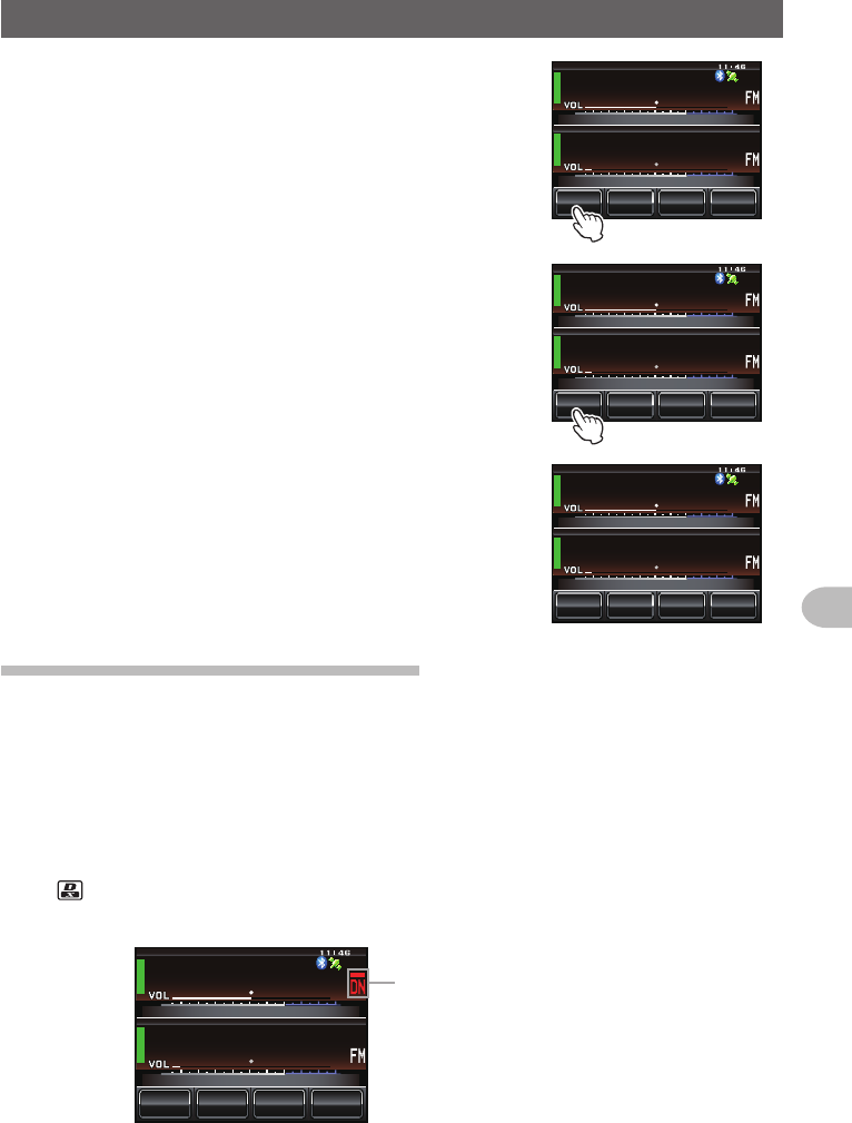
2 Touch [V/M]
The mode will change to the memory mode.
The channel number will be displayed above the
frequency.
The name (tag) assigned to the memory channel will
also be displayed.
/76'
5%12'
/853.
8(1
8(1
ᲹᲽᲸᲸᲸ
ᲸᲸᲸ
3 Touch [V/M] again
The mode will change to the VFO mode and the
frequency will return to the last frequency received.
“VFO” will be displayed above the frequency.
ᲹᲽᲾᲸᲸ
ᲹᲺ᳀;1-1*#/#
/76'
5%12'
/8 53.
8(1
ᲸᲸᲸ
/76'
5%12'
/853.
8(1
8(1
ᲹᲽᲸᲸᲸ
ᲸᲸᲸ
Switchingthecommunicationmode
This radio is equipped with an Automatic Mode Select (AMS) function which
automatically selects any one of four communication modes to match the signal
received.
Besides C4FM digital signals, analog signals are also identified in order to automatically
match the communication mode of the partner station.
* Digital communication can be performed only on the Band A.
Press to display “
▀
○○*” on the screen.
* Display differs depending on the signal received.
/76'
5%12'
/853.
8(1
8(1
ᲹᲽᲸᲸᲸ
ᲸᲸᲸ
AMS時の表示例
Display example when in the AMS
Application for FCC / IC
FCC ID: K6620345X40 / IC: 511B-20345X40
46
Basic Operations
Receiving
When operating in a fixed communication mode, switch to the communication mode using
.
The communication mode will switch in sequence as follows each time is pressed.
“
▀
○○ (AMS)” → “DN (V/D mode)” → “VW/DW (FR mode)” → “FM (Analog)”
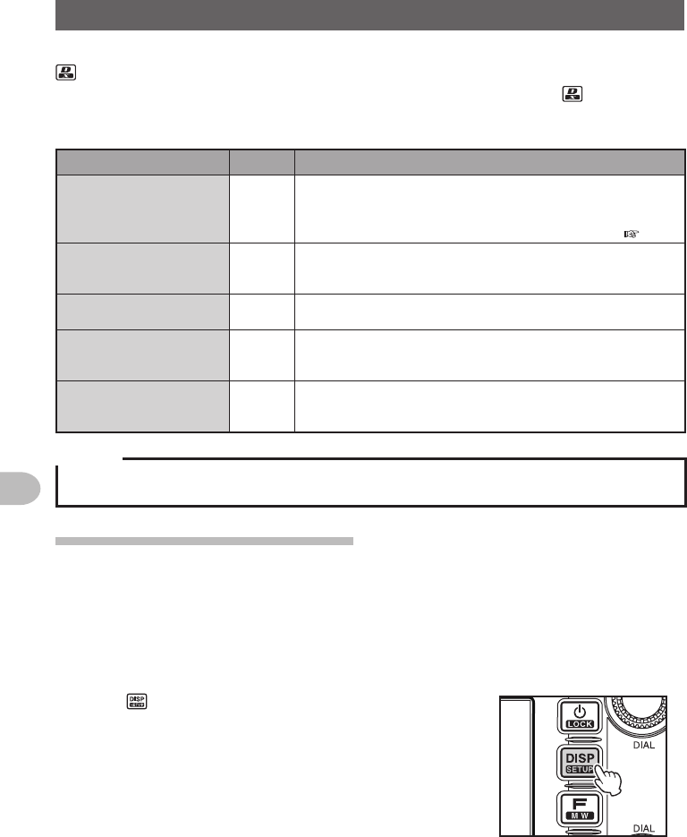
Operatingmode Display Explanationofmodes
AMS
(Automatic Mode Select)
▀
○○ The operating mode is automatically selected from four communication
modes to match the signal received.
(The ○○ part display differs according to the signal received)
The AMS feature settings may be changed via Set-up Menu
( P.174).
V/D mode
(simultaneous voice and data
communication mode)
DN As the audio signal error is detected and repaired at the same time as
the transmission of the digital audio signal, it becomes more difficult
for conversations to be cut off. A basic digital mode of C4FM FDMA.
Voice FR mode
(Voice full-rate mode)
VW Digital voice data is transmitted using the entire 12.5 kHz bandwidth.
High quality voice communication is possible.
Data FR mode
(high speed data
communication mode)
DW High speed data communication mode using the entire 12.5 kHz
bandwidth for data communication.
Automatically switches to this mode for video communication.
Analog FM mode FM Analog communication mode using the FM mode.
This mode is effective for communication when the signal strength is
so weak that the voice is cut off midway in the digital mode.
Caution
In the V/D mode (“DN” displayed), the position information is included in the transmitted signal during
the conversation, but in the Voice FR mode (“VW” displayed), the position information is not included.
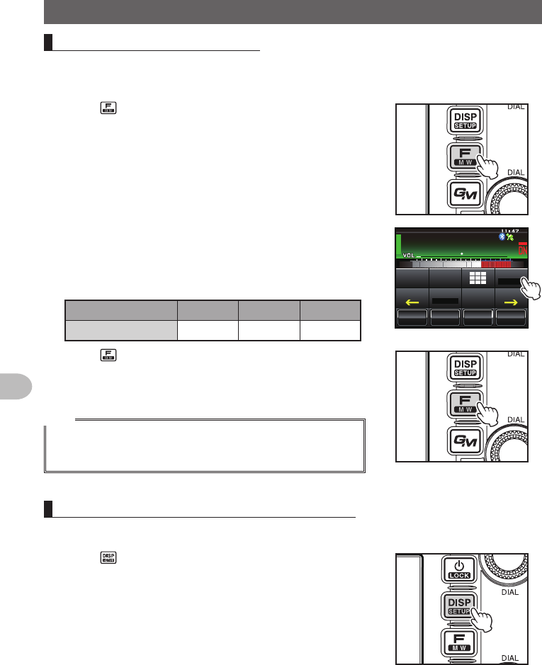
Switchingthemodulationmode
The modulation mode can be selected from “FM”, “NARROW FM” and “AM” in the analog
mode.
When shipped from the factory, the mode is set to “AUTO” where the most optimal
modulation mode is automatically selected according to the frequency.
1 Choose the operating band
2 Press for one second or longer
The set-up menu will be displayed.
Application for FCC / IC
FCC ID: K6620345X40 / IC: 511B-20345X40
47
Basic Operations
Receiving
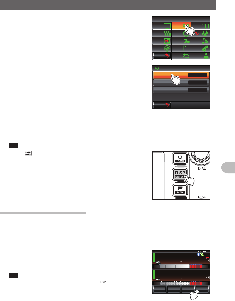
3 Touch [TX/RX]
The menu list will be displayed.
$#%-
$#%-
6:4:
5'672/'07
4'5'6
%.10'
%10(+)9Ჰ4'5
5%#0
&+52.#;
5+) 0#.+0)
#245 126+10
5&%#4&
/'/14;
#
%#..5+) 0
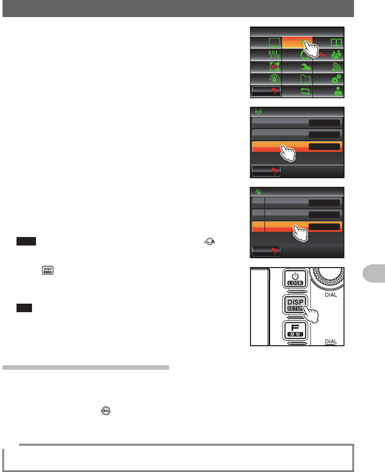
4 Touch [MODE] to select the modulation mode
The modulation mode changes in the following order
each time the screen is touched:
“AUTO (FM)”: Automatically switches the modulation
mode to match the frequency band
“FM”: Switches to the FM mode.
“NARROW FM”: Switches to the Narrow FM mode.
The degree of modulation becomes
half the normal level.
“AM”: Switches to the AM mode.
Tip Factory default value: AUTO (FM)
$#%-
$#%-
6:4:
Ż
Ż
/1&'
&+)+6#.
#7&+1
#761(/
5 Press for one second or longer
The modulation mode is set up and the display
returns to the previous screen.
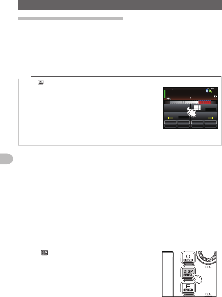
Displayingthebandscope
The band scope can display a graph of the signal activity of the channels surrounding
the memory channel or frequency that has been set up in the operating band. The
display is centered on the current operating frequency.
1 Touch [SCOPE]
[SCOPE] will turn orange and the band scope will be
displayed.
Tip The range to be shown can also be adjusted. Refer to
“Setting the width of the band scope” ( P.172).
ᲹᲽᲾᲸᲸ
8(1
᳀ᲾᲸ
ᲽᲸᲸ61-;1Ჺ
/76'
5%12'
/8 53.
Application for FCC / IC
FCC ID: K6620345X40 / IC: 511B-20345X40
48
Basic Operations
Receiving
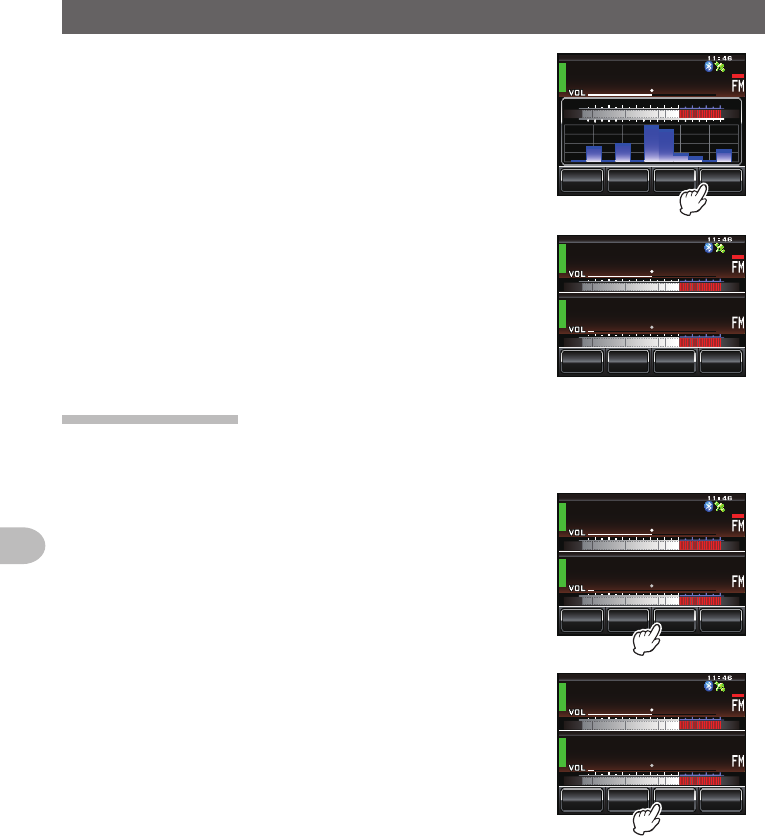
2 Touch [SCOPE] again
The display will return to the dual band screen.
ᲹᲽᲾᲸᲸ
8(1
᳀ᲾᲸ
ᲽᲸᲸ61-;1Ჺ
/76'
5%12'
/8 53.
5%12'
ᲹᲽᲾᲸᲸ
8(1
/76'
ᲽᲿ᳁ᲹᲹ
/8 53.
Mutingtheaudio
The audio in the operating band and sub-band can be muted with just one touch.
1 Touch [MUTE]
[MUTE] will turn orange and the sound will become
inaudible.
ᲹᲽᲾᲸᲸ
8(1
᳀ᲾᲸ
ᲽᲸᲸ61-;1Ჺ
/76'
5%12'
/8 53.
2 Touch [MUTE] again
The sound will become audible.
ᲹᲽᲾᲸᲸ
8(1
᳀ᲾᲸ
ᲽᲸᲸ61-;1Ჺ
/76'
5%12'
/8 53.
Application for FCC / IC
FCC ID: K6620345X40 / IC: 511B-20345X40
49
Basic Operations
Communicating
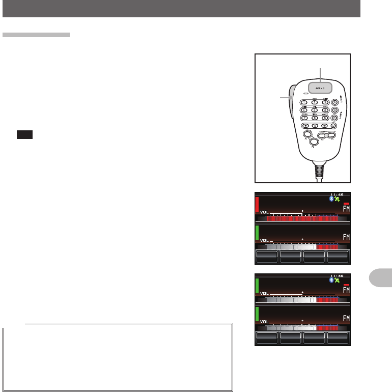
Transmitting
1 Press and hold the microphone [PTT]
A red bar will be displayed on the left of the band
display.
Also, the transmission output level will be displayed
in the PO meter under the VOL meter.
2 Talk directly into the microphone [MIC]
Tip Keep the microphone at a distance of about 1 inch away
from the mouth when talking.
LOCK
P3
P2
P1
7
1
4
8
2
0
5
9
B
A
C
D
3
6
P4
LAMP
DTMF MICROPHONE
MH-48
ABC
JKL
TUV
GHI
PQRS
DEF
MIC
MNO
WXYZ
PTT
MIC
ᲹᲽᲾᲸᲸ
᳀ᲾᲸ
ᲽᲸᲸ61-;1Ჺ
/76'
5%12'
/853.
8(1
3 Release [PTT]
The red bar and PO meter level will disappear and
the radio will return to the receiving state.
Tips
• Refrain from transmitting continuously for a long period of time
as much as possible. The temperature of the main body will
rise and this may result in burns and equipment failure due to
overheating.
• “ERROR TX FREQ” will be displayed when attempting to
transmit on a frequency that is not in the amateur band.
ᲹᲽᲾᲸᲸ
᳀ᲾᲸ
ᲽᲸᲸ61-;1Ჺ
/76'
5%12'
/853.
8(1
Application for FCC / IC
FCC ID: K6620345X40 / IC: 511B-20345X40
50
Basic Operations
Communicating
Adjustingthetransmitpower
When communicating with a nearby station, the transmit power can be reduced to save
on energy consumption.
1 Press
The function menu will be displayed.
2 Touch [TxPWR] to select the transmit power
The transmission power is changed in the following
sequence, each time [TxPWP] is touched.
“HI” → “LO” → “MD”
Model HI MD LO
FTM-400XDR/DE 50 W 20 W 5 W
ᲹᲽᲾᲸᲸ
ᲹᲺ᳀;1-1*#/#
Ჸ
8(1
/76'
5%12'
/8 53.
5-+25'.
1((
&9
6Z294
*+
5%#0 4'8
(9&$#%-
3 Press
The transmit power is set and the display returns to
the previous screen.
Tips
• The current setting will be displayed under [TxPWR] in the
display.
• The default setting when shipped from the factory is “HI”.
Adjustingthesensitivityofthemicrophone
The sensitivity (gain) of the microphone can be adjusted.
1 Press for one second or longer
The set-up menu will be displayed.
Application for FCC / IC
FCC ID: K6620345X40 / IC: 511B-20345X40
51
Basic Operations
Communicating
2 Touch [TX/RX]
The menu list will be displayed.
$#%-
$#%-
6:4:
5'672/'07
4'5'6
%.10'
%10(+)9Ჰ4'5
5%#0
&+52.#;
5+) 0#.+0)
#245 126+10
5&%#4&
/'/14;
#
%#..5+) 0
3 Touch [AUDIO]
The menu list will be displayed.
$#%-
$#%-
6:4:
Ż
Ż
/1&'
&+)+6#.
#7&+1
#761(/
4 Touch [3MICGAIN] to select the sensitivity
The sensitivity will change in the following sequence
each time the screen is touched.
“MIN” → ”LOW” → “NORMAL” → “HIGH” → “MAX”
Tips • The sensitivity can also be selected by pressing .
• Factory default value: NORMAL
$#%-
$#%-
((1
5'2#4#6'
014/#.
57$$#0&/76'
/+:5'2#4#6'
/+%)#+0
#7&+1
Ჹ
Ჺ
5 Press for one second or longer
The sensitivity is set and the display returns to the
previous screen.
Tip The display can also be returned to the previous screen
by touching [BACK] twice.
CommunicatingintheFMmode
1 Choose the operating band
2 Select “FM” as the modulation mode
3 Tune the radio using
4 Press and hold the microphone [PTT] to talk
Tip
The Narrow FM mode can also be used. Set the mode to [NARROWFM] under [TX/RX] → [MODE]
in the set-up menu.
Application for FCC / IC
FCC ID: K6620345X40 / IC: 511B-20345X40
52
Basic Operations
Communicating
Communicatingusingtherepeater
This radio includes an ARS (Automatic Repeater Shift) function which permits
communication through the repeater automatically just by setting the receiver to the
repeater frequency.
1 Set the receive frequency to the repeater frequency
“-” or “+” appears on top of the display.
2 Press [PTT], to begin communicating through the repeater
Tips
• Press and touch [REV] to reverse the transmission and reception frequencies temporarily to
check whether direct communication with the partner station is
possible.
• When reversing the frequencies, [REV] will turn orange.
• When [REV] is touched one more time, the reverse is cancelled.
• When the settings are changed in the set-up menu, this radio can
be used in even more convenient ways.
The ARS function can be turned off under “CONFIG” → “4 AUTO
RPT SHIFT”.
The repeater shift direction can be set under “CONFIG” → “5 RPT SHIFT”.
The repeater shift width can be changed under “CONFIG” → “6 RPT SHIFT FREQ”.
●Repeatershift
The FTM-400XDR/DE has been configured, at the factory, for the repeater shifts
customary in the country where it is sold. For the 144 MHz band, this usually will be 600
kHz, while the 430 MHz shift will be 1.6 MHz or 7.6 MHz.
Depending on the part of the band in which you are operating, the repeater shift may
be either downward (−) or upward (+), and one of these icons will appear on the display
when repeater shifts have been enabled.
●Automaticrepeatershift(ARS)
The FTM-400XDR/DE ARS feature causes the appropriate repeater shift to be
automatically applied whenever it is tuned into the designated repeater sub-bands.
If the ARS feature does not appear to be working, you may have accidentally disabled it.
To re-enable ARS:
1 Press for one second or longer
The set-up menu will be displayed.
/76'
5%12'
/8 53.
᳁ ᳀ᲾᲸ
ᲽᲸ
ᲺᲹ61-;1Ჺ
᳁ ᲿᲸᲸ
8(1
5-+25'.
1((
&9
6Z294
*+
5%#0 4'8
(9&$#%-
Application for FCC / IC
FCC ID: K6620345X40 / IC: 511B-20345X40