Yaesu Musen 20345X40 AMATEUR RADIO WITH SCANNING RECEIVER User Manual OM
Yaesu Musen Co., Ltd. AMATEUR RADIO WITH SCANNING RECEIVER OM
Contents
- 1. User Manual
- 2. User Manual 1
- 3. User Manual 2
- 4. User Manual 3
- 5. User Manual 4
- 6. User Manual 5
- 7. User Manual 6
- 8. User Manual 7
- 9. User Manual 8
- 10. User Manual 9
- 11. User Manual 10
- 12. User Manual 11
- 13. User Manual 12
- 14. User Manual 13
- 15. User Manual 14
- 16. User Manual 15
- 17. User Manual 16
- 18. User Manual 17
- 19. User Manual 18
- 20. User Manual 19
- 21. User Manual 20
- 22. User Manual 21
User Manual 3
29
Installation and Connection
ConnectingtheRadio
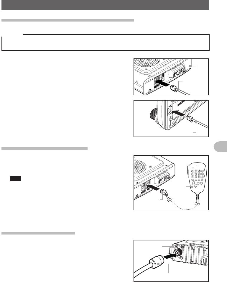
Connectingthecontrollertothemainbody
Caution
Make sure the power supply is switched OFF before connecting the cable between the controller and
the main body.
1 Plug the connector of the controller cable into the
[CONTROL] jack at the front of the main body
until a click sound is heard
本体
コントロール
ケーブル
Main
body
Controller
cable
2 Plug the other connector of the controller cable
into the [CONTROL] jack at the back of the
controller until a click sound is heard
コントロールケーブル
コントローラ
Controller
Controller cable
Connectingthemicrophone
1 Plug the microphone connector into the [MIC]
jack at the front of the main body until a click
sound is heard
Tips • To remove the microphone, pull the connector out
while pressing the latch.
• Using the optional microphone extension kit “MEK-
2”, a microphone with a 8-pin connector can be
used. A microphone extension cable (about 3 m
long) is also included in MEK-2. Use it to install the
microphone in locations which cannot be reached
by the attached microphone cable.
LOCK
P3
P2
P1
7
1
4
8
2
0
5
9
B
A
C
D
3
6
P4
LAMP
DTMF MICROPHONE
MH-48
ABC
JKL
TUV
GHI
PQRS
DEF
MNO
WXYZ
MIC
コネクタ
マイクロホン
Microphone
Connector
Connectingtheantenna
1 Attach the antenna co-axial cable to the [ANT]
terminal at the back of the main body and tighten
the connector
同軸ケーブル端子
本体(後面)
Main body
(rear side)
Co-axial cable connector
Application for FCC / IC
FCC ID: K6620345X40 / IC: 511B-20345X40
30
Installation and Connection
ConnectingthePowerSupply
Connectingthecarbattery
When using this radio as a mobile unit, connect the DC power supply cable to the
negative ground 12 V car battery.
Cautions
zUse the radio in a car with a negative ground 12 V DC system, where the minus (-) pole of the
battery is connected to the car body.
zDo not connect the radio to the 24 V battery of a large vehicle.
zDo not use the cigarette lighter inside the car as a power source.
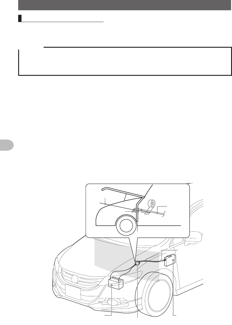
(1)Cableroutingfrominsidethecartotheenginecompartment
Rout the DC power supply cable to the engine compartment, passing it through a
grommet in the fire wall from the passenger side.
1 Feed a hardened wire from the engine compartment through the grommet into the
interior of the car
2 Hook the end of the “feed” wire with the “bare wire” end of the provided DC power
supply cable
3 Fold and bend the ends of the wires and wind insulation tape around them
4 Pull the “feed” wire back into the engine compartment
The DC power supply cable will be pulled through the grommet into the engine
compartment.
5 Peel off the tape and remove the DC power supply cable from the “feed” wire
②
テープ
かための針金
グロメット
バッテリー(12V)
①グロメットに貫通させる
DC電源
ケーブル
無線機本体
Hardened wire
Grommet
Battery (12V)
Tape
DC power
supply cable
(accessory)
DC power
supply
cable
➀Pass the cable through the grommet
Radio main
body
Application for FCC / IC
FCC ID: K6620345X40 / IC: 511B-20345X40
31
Installation and Connection
ConnectingthePowerSupply
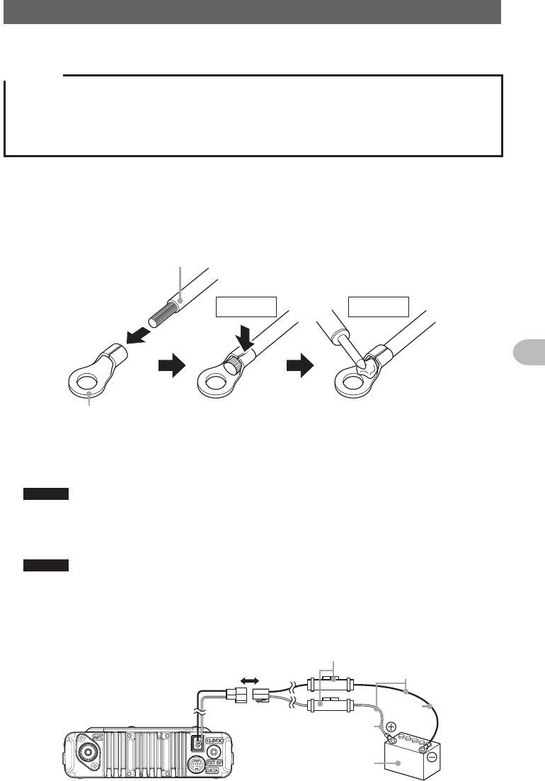
(2)Connectingthepowersupplycable
Cautions
zDo not use a DC power supply cable other than the one that is provided or specified.
zDo not rout the DC power supply cable where objects may be placed on top of it or persons may
step on the cable.
zDo not use the DC power supply cable with the fuse holder cut off.
zDo not reverse the polarity (positive and negative) when connecting the battery.
1 Disconnect the minus (-) terminal from the battery
This prevents short-circuiting the 12 V DC voltage while working on the cables.
2 Obtain commercially available terminals and crimp or solder both the red (+) and
black (-) wire ends of the DC power supply cable
DC電源ケーブル
圧着端子
圧着 ハンダ付け
DC power cable
Crimped
terminal
Crimping Soldering
3 Connect the red wire (+) of the DC power supply cable to the positive (+) terminal of
the battery
Caution Fasten the DC power supply cable securely so that the terminals do not get disconnected.
4 Reconnect the negative (-) terminal of the battery that was disconnected
5 Connect the black wire (-) of the DC power supply cable to the negative (-) terminal
of the battery
Caution Fasten the DC power supply cable securely so that the terminals do not get disconnected.
6 Connect the DC power supply cable to the connector of the power cord of the main
body
Press the plug into the connector until a click sound is heard.
本体後面
電源コード
(DC(直流)
13.8V) 黒色
DC電源ケー
ブル
(付属品)
DC12Vバッテリー
ヒューズ
ホルダー
赤色
Rear side of main body
Power cord (DC
(direct current)
13.8 V)
Fuse holder DC power
supply cable
(accessory)
DC 12 V battery
Red
Black
Application for FCC / IC
FCC ID: K6620345X40 / IC: 511B-20345X40
32
Installation and Connection
ConnectingthePowerSupply
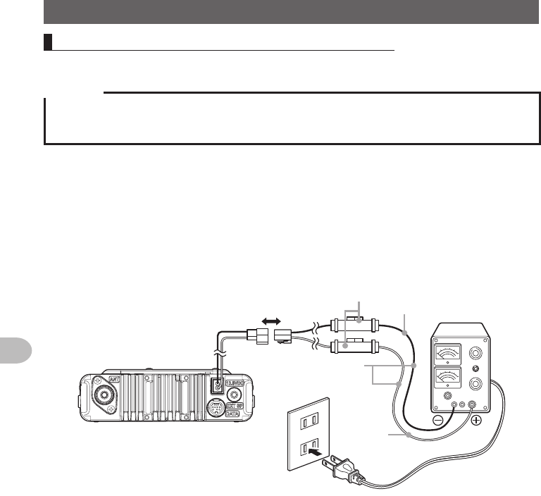
Connectingtheexternalpowersupplyequipment
When using this radio as a fixed station, use an external 12 V DC power source.
Cautions
zUse an external power source capable of supplying DC 13.8 V, a current capacity of 20 A or more
(FTM-400XDR/DE).
zMake sure to switch OFF the power of the external power source before connecting.
1 Connect the red wire (+) of the provided DC power supply cable to the positive
(+) terminal of the external power source, and the black wire (-) to the negative (-)
terminal of the external power source
2 Connect the DC power supply cable to the connector of the power cord of the main
body
Press the plug into the connector until a click sound is heard.
本体後面
電源コード
(DC(直流)
13.8V)
黒色 直流安定化
電源装置
AC100V
コンセント
DC電源ケーブル
(付属品)
ヒューズ
ホルダー
赤色
Power cord (DC
(direct current)
13.8 V)
Rear side of main body
Black
Red
AC line
outlet
DC power supply
cable (accessory)
Fuse holder
Direct current
13.8 V DC power
supply
Application for FCC / IC
FCC ID: K6620345X40 / IC: 511B-20345X40

33
Installation and Connection
SettingUpthemicro-SDCard
The following operations can be carried out by using a micro-SD card in this radio.
• Backing up the information and settings of the radio
• Saving the information in the memory channels
• Saving the settings in the set-up mode
• Saving the GPS log data
• Saving photos taken with the optional speaker microphone with camera “MH-85A11U”
• Saving data that has been downloaded using the GM function and WIRES-X function
• Exchanging the saved data among multiple radios
Micro-SDcardsthatcanbeused
2 GB, 4 GB, 8 GB, 16 GB and 32 GB micro-SDHC cards can be used in this radio.
Cautions
zThe micro-SD or micro-SDHC cards are not provided with the product.
zNot all micro-SD and micro-SDHC cards sold commercially are guaranteed to work with this product.
Thingstonotewhenusingmicro-SDcards
• Do not bend the micro-SD card or place heavy objects on top of it.
• Do not touch the terminal face of the micro-SD card with your bare hands.
• Micro-SD cards that are initialized in other devices may not record normally when
used in this device. Re-initialize the micro-SD card in this radio when using a card
that has been initialized in another device. (Refer to Page 35 on how to initialize the
memory card)
• Do not pull the micro-SD card out, or switch the power to the radio OFF when reading
or writing data to the card.
• Do not insert anything other than a micro-SD card into the micro-SD card slot of the
radio.
• Do not pull out or insert the micro-SD card with unreasonable force.
• When a single micro-SD card is used for a long period of time, writing and deletion of
data may become disabled. Use a new micro-SD card when data can no longer be
written or erased.
• Note that Yaesu shall not be liable for any damages suffered as a result of data loss
or corruption in use of the micro-SD card.
Application for FCC / IC
FCC ID: K6620345X40 / IC: 511B-20345X40
34
Installation and Connection
SettingUpthemicro-SDCard
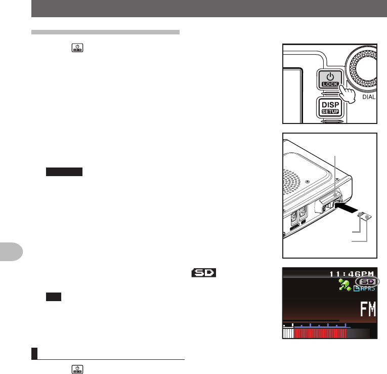
Installingthemicro-SDcard
1 Press for 2 seconds or longer to switch off the
power to the main body
2 Insert the micro-SD card into the micro-SD card slot,
with the terminal face on top, until a click sound is
heard
Cautions z Insert the micro-SD card in the correct direction.
z Do not touch the terminal of the micro-SD card
with your hands.
端子面
microSD
カードスロット
microSDカード
micro-SD
card slot
Terminal face
micro-SD card
After the power is switched on, the “ ” icon will
be displayed at the top right of the display.
Tip It may take a while for the icon to appear depending on
the card capacity.
ᲸᲸ
#/#
Removingthemicro-SDcard
1 Press for 2 seconds or longer to switch off the power to the main body
2 Push in on the microSD card
A click sound will be heard and the micro-SD card will be pushed outward.
3 Pull the micro-SD card from the micro-SD card slot
Application for FCC / IC
FCC ID: K6620345X40 / IC: 511B-20345X40
35
Installation and Connection
SettingUpthemicro-SDCard
Initializingthemicro-SDcard
When using a new micro-SD card, initialize the micro-SD card according to the following
procedure.
Caution
Upon initialization, all the data recorded in the micro-SD card will be erased. Check the contents of
the micro-SD card before initialization.
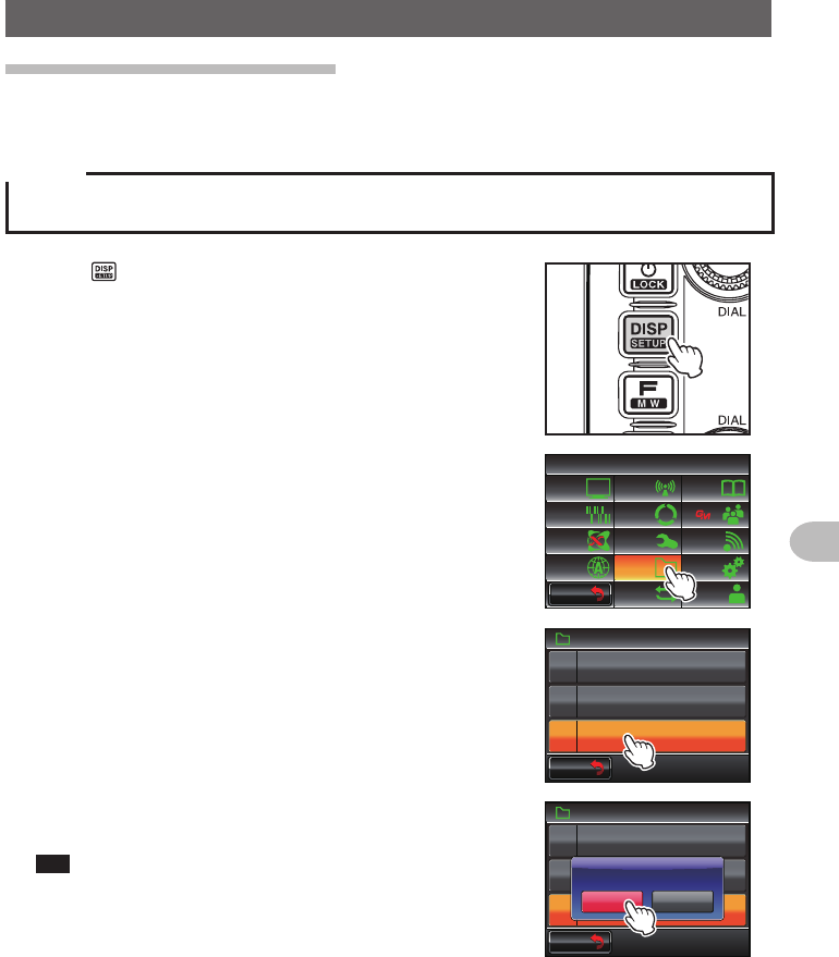
1 Press for one second or longer
The set-up menu will be displayed.
2 Touch [SDCARD]
The menu list will be displayed.
$#%-
$#%-
6:4:
5'672/'07
4'5'6
%.10'
%10(+)9Ჰ4'5
5%#0
&+52.#;
5+) 0#.+0)
#245 126+10
5&%#4&
/'/14;
#
%#..5+) 0
3 Touch [3FORMAT]
The format confirmation screen will be displayed.
5&%#4&
(14/#6
)4172+&
$#%-72
Ჹ
Ჺ
$#%-
$#%-
4 Touch [OK?]
The micro-SD card will be initialized.
Tip Touch [Cancel] to stop the initialization.
“Completed” will be displayed when initialization
is completed and the screen will then return to the
menu list.
5&%#4&
(14/#6
)4172+&
$#%-72
Ჹ
Ჺ
$#%-
$#%-
%CPEGᲴ1-!
(14/#6
Application for FCC / IC
FCC ID: K6620345X40 / IC: 511B-20345X40
36
Basic Operations
Receiving
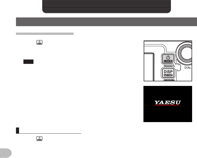
Turningthepoweron
1 Press for 2 seconds or longer
The power will be switched on, and the display will
appear on the screen.
Tips • When switching the power on for the first time after
purchasing, or after resetting, a screen requesting
the call sign of your own station be entered, will be
displayed.
• From the second time onwards, the call sign of your
own station entered the first time will be displayed.
2%ᲹᲹ Ჺ
;*,
Switchingthepoweroff
1 Press for 2 seconds or longer
The screen display will disappear, and the power will be switched off.
BasicOperations
Application for FCC / IC
FCC ID: K6620345X40 / IC: 511B-20345X40
37
Basic Operations
Receiving
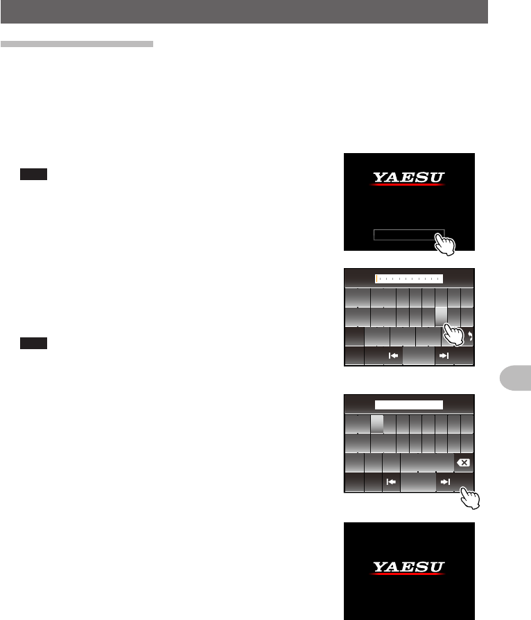
Inputingthecallsign
When switching the power on for the first time after purchasing, or after resetting
the device, a screen requesting the call sign of your own station be entered will be
displayed.
The call sign is used to identify the transmitting station when communicating in the
digital mode.
1 Touch the blinking [CALLSIGN]
Tips The display will change to the character input screen
automatically if there are no operations for about 3
seconds.
%#..5+)0
2ᲴGCUGGPVGT
/CZᲹᲸᲴGVVGTU
;QWT%CᲴ ᲴUKIP
2 Touch a character key
The touched character will be displayed at the top of
the screen.
Enter each character of your call sign.
Tips • Up to 10 characters (letters, numbers, and a hyphen )
can be entered.
• Refer to Page 23 on how to operate the character input
screen.
39'46; 7 +12
#5&()*,- .
<:%8$0/
#$% 5RCEG
'06
@
ᲹᲺ
%CRU
$#%-
3 Touch [ENT]
The screen will change.
Thereafter, the entered call sign is displayed at the
bottom of the power on screen, and the display will
switch to the frequency display screen (dual band
screen).
ᲹᲺ
ᲽᲾᲿ᳀ ᳁ ᳂
"
#$% 5RCEG
'06
%CPEGᲴ
!
@
ᲹᲺ
2%ᲹᲹ Ჺ
;
*,
2%ᲹᲹ Ჺ
;*,
Application for FCC / IC
FCC ID: K6620345X40 / IC: 511B-20345X40
38
Basic Operations
Receiving
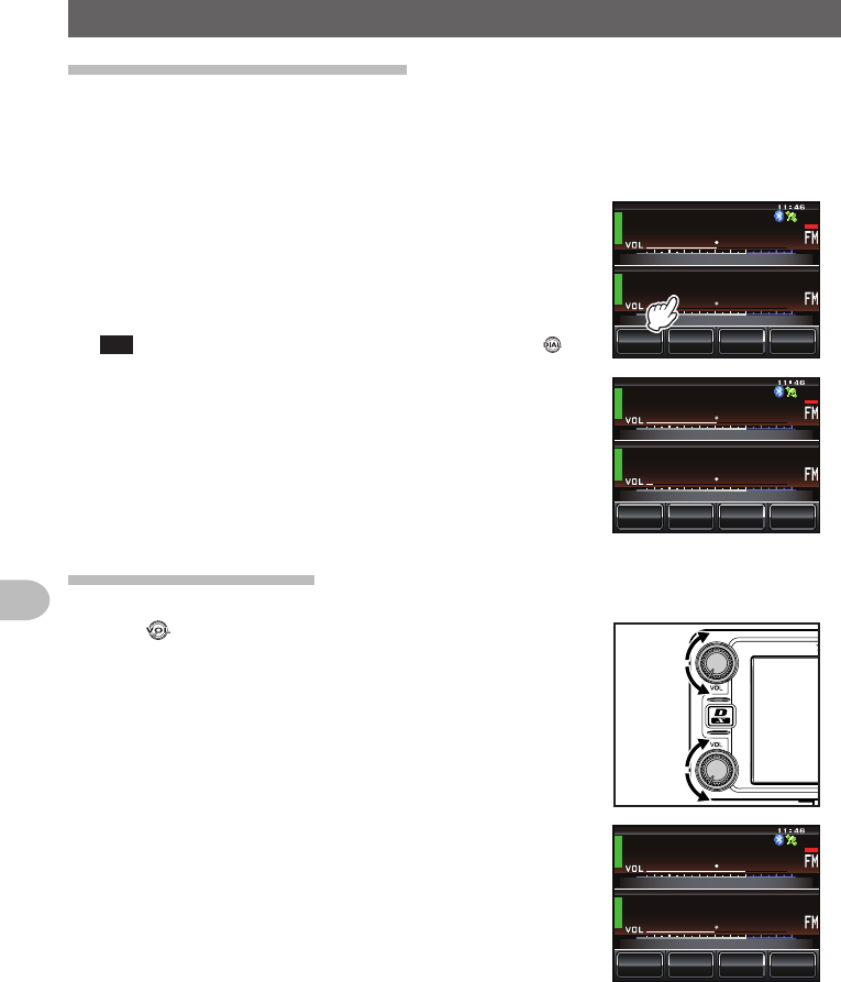
Switchingtheoperatingband
The two bands are displayed at the top and bottom of the dual band screen. The
frequency and the modulation mode of the “operating band” can be changed. The band
that is not in operation is called the “sub-band”.
1 Touch the frequency display area of the band that
you would like to set as the operating band
The characters of the tag and frequency will be
displayed in white. The sub-band characters will be
displayed in gray.
Tip The operating band can also be changed by pressing .
ᲹᲽᲸᲸᲸ
ᲸᲸᲸ
/76'
5%12'
/853.
8(1
8(1
ᲹᲽᲸᲸᲸ
ᲸᲸᲸ
/76'
5%12'
/853.
8(1
8(1
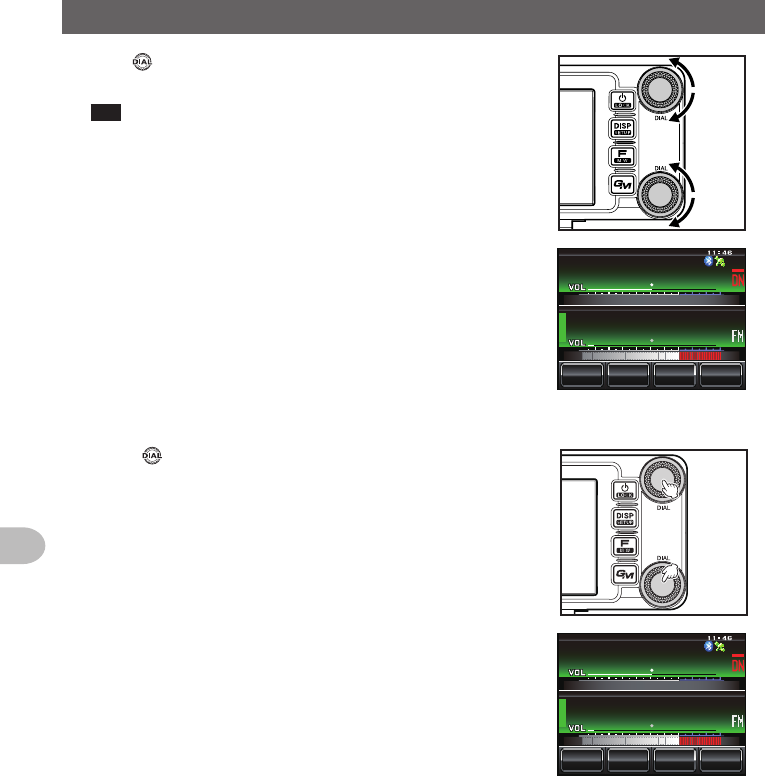
Adjustingthevolume
1 Turn
The volume level will be displayed in the VOL meter
below the frequency.
/76'
5%12'
/853.
ᲹᲽᲸᲸᲸ
ᲸᲸᲸ
8(1
8(1
Application for FCC / IC
FCC ID: K6620345X40 / IC: 511B-20345X40
39
Basic Operations
Receiving
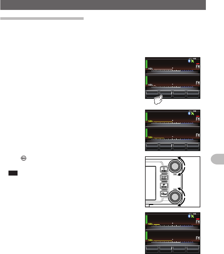
Adjustingthesquelchlevel
Annoying noises can be muted when a signal cannot be detected. Band A and Band B
squelch levels can be individually adjusted. Noise can be canceled more easily when
the squelch level is increased but it may become more difficult to pick up weak signals.
Adjust the squelch level as required.
1 Touch [SQL]
When [SQL] turns orange, the VOL meter below the
frequency will change to show the SQL level setting.
ᲹᲽᲸᲸᲸ
ᲸᲸᲸ
/76'
5%12'
/853.
8(1
8(1
ᲹᲽᲸᲸᲸ
ᲸᲸᲸ
/76'
5%12'
/853.
8(1
8(1
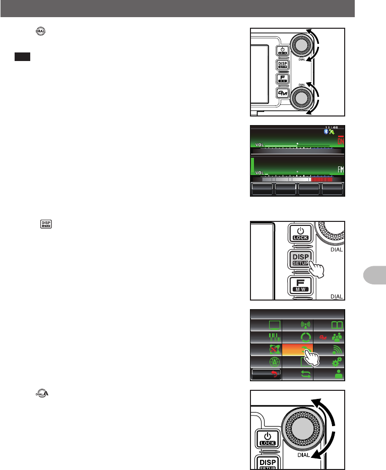
2 Turn to adjust the squelch level
The level will be displayed in the SQL meter.
Tip The SQL meter will return to the VOL meter if there is no
operation for three seconds.
ᲹᲽᲸᲸᲸ
ᲸᲸᲸ
/76'
5%12'
/853.
8(1
8(1
Application for FCC / IC
FCC ID: K6620345X40 / IC: 511B-20345X40
40
Basic Operations
Receiving
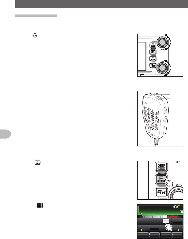
Tuningtheradio
●Usingtheknobs
1 Turn
The frequency will increase when the knob is turned
in a clockwise direction and decrease when turned in
a counter-clockwise direction.
●Usingthemicrophonekeys
1 Press [UP] or [DWN]
The frequency increases when [UP] is pressed, and
decreases when [DWN] is pressed.
UP
DWN
●Enteringthenumericalfigures
1 Press
The function menu will be displayed.
2 Touch []
The number input screen will be displayed.
ᲹᲽᲾᲸᲸ
ᲹᲺ᳀;1-1*#/#
᳀ᲾᲸ
/76'
5%12'
/853.
8(1
5-+25'.
1((
&9
6Z294
*+
5%#0 4'8
(9&$#%-
Application for FCC / IC
FCC ID: K6620345X40 / IC: 511B-20345X40
41
Basic Operations
Receiving
3 Touch a number key
The touched number will be displayed at the top of
the screen.
Tip Refer to Page 23 for operation of the number input
screen.
ᲹᲺ
ᲽᲾ
Ჿ᳀᳁
᳂
#
$
%
&
5RCEG
'06
᳀ᲾᲸ
$#%-
4 Touch [ENT]
The display will return to the function menu and
the entered frequency of the operating band will be
displayed at the top of the screen.
ᲹᲺ
ᲽᲾ
Ჿ᳀᳁
᳂
#
$
%
&
5RCEG
'06
ᲹᲽ ᲾᲺᲸ
$#%-
ᲹᲽᲾᲸᲸ
ᲹᲺ᳀;1-1*#/#
ᲹᲽ ᲾᲺᲸ
/76'
5%12'
/853.
8(1
5-+25'.
1((
&9
6Z294
*+
5%#0 4'8
(9&$#%-
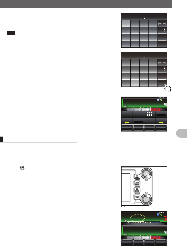
Changingthefrequencysteps
The frequency step while tuning with the knob or [UP]/[DWN] keys of the microphone,
can be changed.
●Changingthefrequencystepto1MHztemporarily
1 Press of the operating band, or touch the
frequency display area of the operating band
The MHZ field in the frequency display will blink.
ᲹᲽᲾᲸᲸ
8(1
᳀ᲾᲸ
ᲽᲸᲸ61-;1Ჺ
/76'
5%12'
/853.
Application for FCC / IC
FCC ID: K6620345X40 / IC: 511B-20345X40
42
Basic Operations
Receiving
2 Turn of the operating band
The frequency will change in 1 MHz steps
Tip When there is no operation for three seconds, the MHz
field will stop blinking and the frequency step will return
to the normal step.
ᲹᲾᲾᲸᲸ
8(1
᳀ᲾᲸ
ᲽᲸᲸ61-;1Ჺ
/76'
5%12'
/853.
●Changingthefrequencystepto5MHztemporarily
1 Press for one second or longer
The kHz frequency digits will not be shown on the
screen.
ᲹᲽ
8(1
᳀ᲾᲸ
ᲽᲸᲸ61-;1Ჺ
/76'
5%12'
/853.
Application for FCC / IC
FCC ID: K6620345X40 / IC: 511B-20345X40
43
Basic Operations
Receiving
2 Turn
The frequency will change in steps of 5 MHz.
Tip When there is no operation for three seconds, the kHz
digits will be displayed and the frequency step will return
to the normal step.
ᲹᲸ
8(1
᳀ᲾᲸ
ᲽᲸᲸ61-;1Ჺ
/76'
5%12'
/853.
●Changingthefrequencystepusingtheset-upmenu
1 Press for one second or longer
The set-up menu will be displayed.
2 Touch [CONFIG]
The menu list will be displayed.
$#%-
$#%-
6:4:
5'672/'07
4'5'6
%.10'
%10(+)9Ჰ4'5
5%#0
&+52.#;
5+) 0#.+0)
#245 126+10
5&%#4&
/'/14;
#
%#..5+) 0
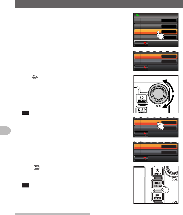
3 Turn or touch the screen to select [7FMAM
STEP]
Application for FCC / IC
FCC ID: K6620345X40 / IC: 511B-20345X40
44
Basic Operations
Receiving
4 Touch [7FMAMSTEP]
The frequency step that is currently set up will
change to orange.
$#%-
$#%-
%10(+)
4265*+(6(4'3
(/#/56'2
$''2
/*\
.19
#761
1((
4265*+(6
$#%-
$#%-
4265*+(6(4'3
(/#/56'2
$''2
/*\
.19
#761
5 Turn to select the frequency step
The setting will change in the following sequence:
AUTO → 5.00 KHz → 6.25 KHz → 8.33 KHz (air
band only) → 10.00 KHz → 12.50 KHz → 15.00 KHz
→ 20.00 KHz → 25.00 KHz → 50.00 KHz →
100.00 KHz
Tip Factory default value: AUTO
6 Touch [7FMAMSTEP]
The selected frequency step will be set, changing
from orange to green.
$#%-
$#%-
4265*+(6(4'3
(/#/56'2
$''2
/*\
-*\
.19
$#%-
$#%-
4265*+(6(4'3
(/#/56'2
$''2
/*\
-*\
.19
7 Press for one second or longer
The frequency step will be set and the display will
return to the previous screen.
Tip The display can also be returned to the previous screen
by touching [BACK] twice.
Switchingtheoperatingmode
The operating mode can be switched between the VFO mode where the frequency
can be freely set, and the memory mode where the channels saved in the memory are
recalled for operation.
1 Choose the operating band
Application for FCC / IC
FCC ID: K6620345X40 / IC: 511B-20345X40