Yaesu Musen 20345X40 AMATEUR RADIO WITH SCANNING RECEIVER User Manual OM
Yaesu Musen Co., Ltd. AMATEUR RADIO WITH SCANNING RECEIVER OM
Contents
- 1. User Manual
- 2. User Manual 1
- 3. User Manual 2
- 4. User Manual 3
- 5. User Manual 4
- 6. User Manual 5
- 7. User Manual 6
- 8. User Manual 7
- 9. User Manual 8
- 10. User Manual 9
- 11. User Manual 10
- 12. User Manual 11
- 13. User Manual 12
- 14. User Manual 13
- 15. User Manual 14
- 16. User Manual 15
- 17. User Manual 16
- 18. User Manual 17
- 19. User Manual 18
- 20. User Manual 19
- 21. User Manual 20
- 22. User Manual 21
User Manual 20
194
Customize Menu Settings and User Preferences
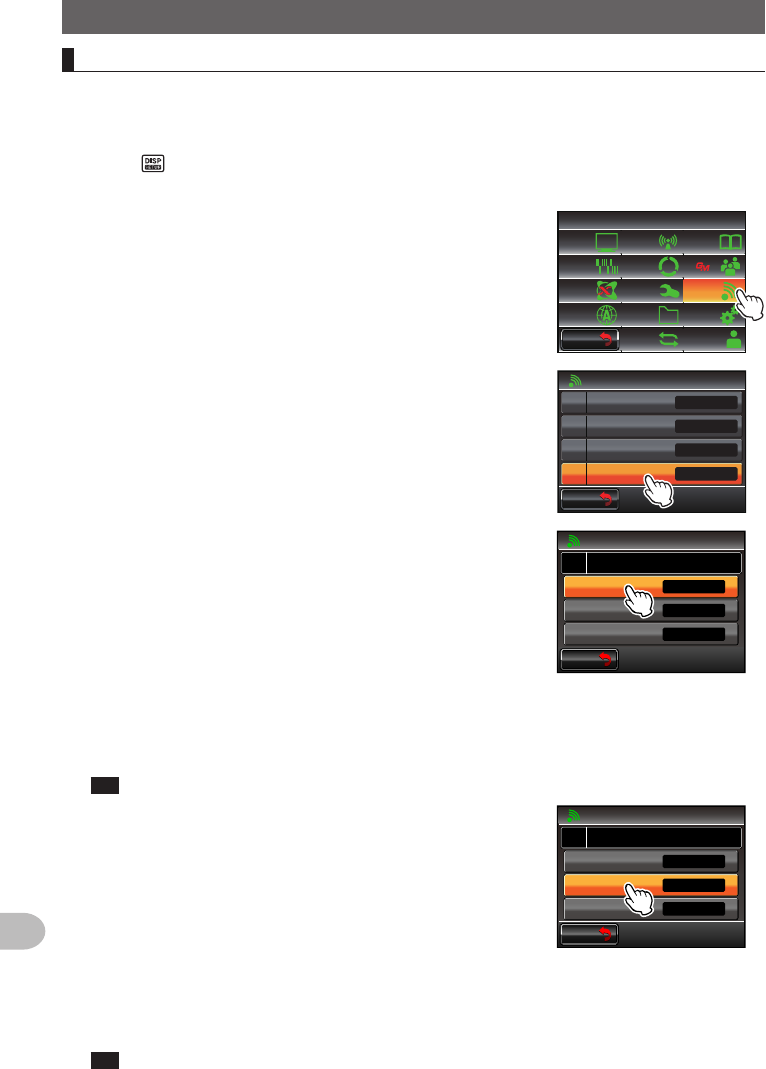
UsingtheSet-upMenu
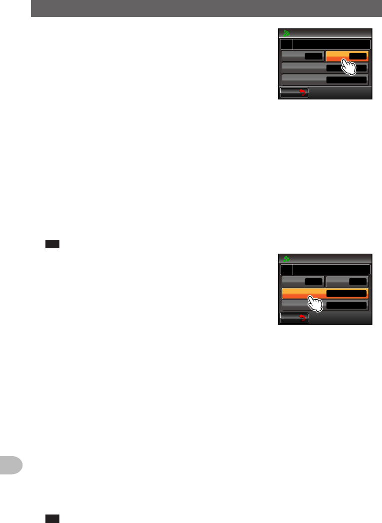
5 Touch [OUTPUT] to select the output function of the
COM port
The setting changes as follows each time it is
touched.
“OFF(camera)” → “GPS OUT” → “PACKET” →
“WAYPOINT”
OFF (camera): The output function of the COM port
is not used (invalid operation).
GPS OUT: Outputs the GPS data obtained by the
radio.
PACKET: Outputs the AX.25 packet communication
data received using the in-built modem
function.
WAYPOINT: Outputs the position information of
other station beacons obtained from the
APRS packets received as WAYPOINT
data.
Tip Factory default value: OFF (camera)
$#%-
$#%-
%1/21465'66+0)
1((ECOGTC
52''&
92(+.6'4
176276
᳁ᲾᲸᲸDRU
#..
92(14/#6 0/'#
Ჹ
#
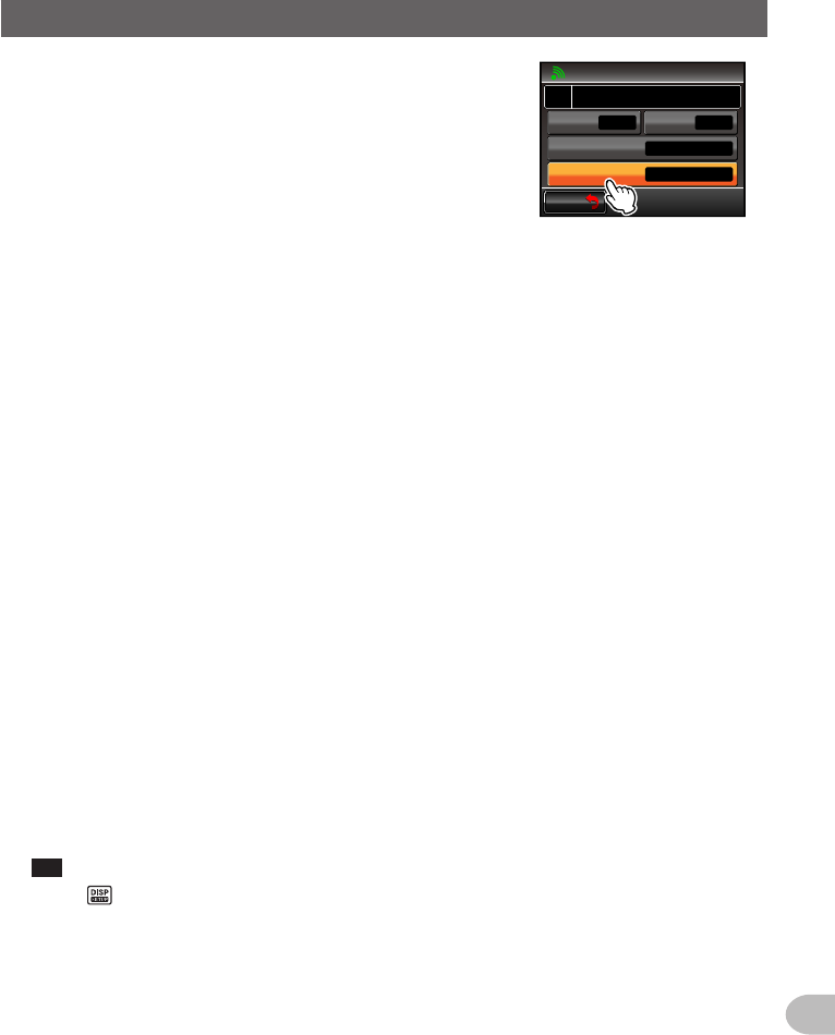
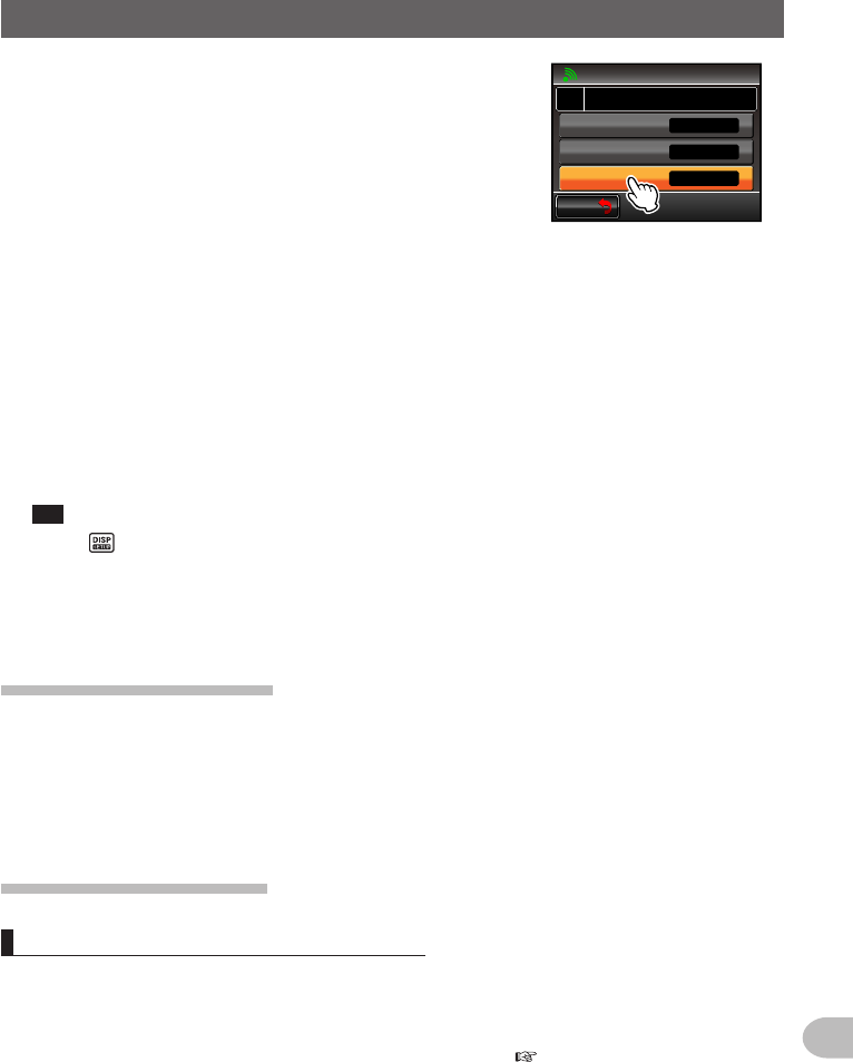
6 Touch [WPFORMAT] to select the data format
This sets the number of digits in the call sign
information of the APRS beacon station appended
to each data when “WAYPOINT” is selected in Step
5 (the data will be output using the NMEA-0183
$GPWPL format).
The setting changes as follows each time it is
touched.
“NMEA 9” → “NMEA 8” → “NMEA 7” → “NMEA 6”
NMEA 9: The call sign will be limited to 9 digits on the
right (Example: The call sign information for
JQ1YBG-14 is “JQ1YBG-14”).
NMEA 8: The call sign will be limited to 8 digits on the
right (Example: The call sign information for
JQ1YBG-14 is “Q1YBG-14”).
NMEA 7: The call sign will be limited to 7 digits on the
right (Example: The call sign information for
JQ1YBG-14 is “1YBG-14”).
NMEA 6: The call sign will be limited to 6 digits on the
right (Example: The call sign information for
JQ1YBG-14 is “YBG-14”).
Tip Factory default value: NMEA 9
$#%-
$#%-
%1/21465'66+0)
9#;21+06
52''&
92(+.6'4
176276
᳁ᲾᲸᲸDRU
#..
92(14/#6 0/'#
Ჹ
#
Application for FCC / IC
FCC ID: K6620345X40 / IC: 511B-20345X40
195
Customize Menu Settings and User Preferences
UsingtheSet-upMenu
7 Touch [WPFILTER] to select the forwarding content
This sets the type of beacon that you would like to
output when “WAYPOINT” is selected in Step 5.
The setting changes as follows each time it is
touched.
“ALL” → “MOBILE” → “FREQUENCY” → “OBJECT/
ITEM” → “DIGIPEATER” → “VoIP”→ “WEATHER” →
“YAESU” → “CALL RINGER” → “RNG RINGER”
ALL: Outputs all beacons received.
MOBILE: Outputs only mobile stations.
FREQUENCY: Outputs only the stations with
frequency information.
OBJECT/ITEM: Outputs only the object station or
item station.
DIGIPEATER: Outputs only the digital repeater
station.
VoIP: Outputs only VoIP stations such as WIRES.
WEATHER: Outputs only the weather station.
YAESU: Outputs only stations which are using Yaesu
transceivers.
CALL RINGER: Outputs only the information of the
call sign ringer station set using
[10APRSRINGER(CALL)] in the
APRS set-up menu.
RNG RINGER: Outputs only the information of
the station deemed to be the
approaching station using the
[9APRSRINGER] range ringer
function in the APRS set-up menu.
Tip Factory default value: ALL
$#%-
$#%-
%1/21465'66+0)
9#;21+06
52''&
92(+.6'4
176276
᳁ᲾᲸᲸDRU
#..
92(14/#6 0/'#
Ჹ
#
8 Press for one second or longer
The COM port will be set and the display will return to the previous screen.
Application for FCC / IC
FCC ID: K6620345X40 / IC: 511B-20345X40
196
Customize Menu Settings and User Preferences
UsingtheSet-upMenu
SettingtheoperatingbandoftheAPRSanddatacommunication
The operating band of the APRS (internal modem) and data communication (when using
the [DATA] jack at the back of the main body) can be set.
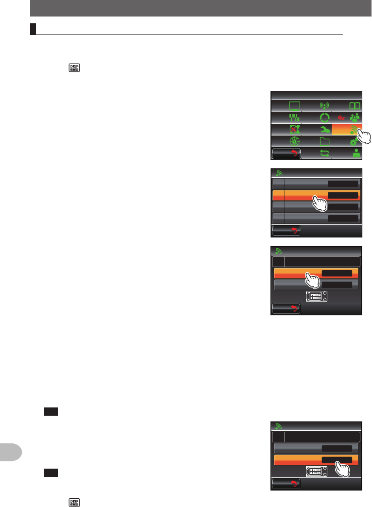
1 Press for one second or longer
The set-up menu will be displayed.
2 Touch [DATA]
$#%-
$#%-
6:4:
5'672/'07
4'5'6
%.10'
%10(+)9Ჰ4'5
5%#0
&+52.#;
5+) 0#.+0)
#245 126+10
5&%#4&
/'/14;
#
%#..5+) 0
3 Touch [2DATABANDSELECT]
The screen for the detailed settings will be displayed.
Ż
Ż
Ż
#$#0&5'.'%6
%1/21465'66+0)
#52''&
Ჹ
Ჺ
Ż
#537'.%*
#
$#%-
$#%-
4 Touch [APRS] to select the APRS operating band
The setting changes as follows each time it is
touched.
“A-BAND FIX” → “B-BAND FIX” → “A=TX/B=RX” →
“A=RX/B=TX” → “MAIN BAND” → “SUB BAND”
A-BAND FIX: The upper band will be selected.
B-BAND FIX: The lower band will be selected.
A=TX/B=RX: Transmits using the upper band and
receives using the lower band.
A=RX/B=TX: Receives using the upper band and
transmits using the lower band.
MAIN BAND: The main band will be selected.
SUB BAND: The sub-band will be selected.
Tip Factory default value: B-BAND FIX
$#%-
$#%-
#$#0&5'.'%6
#
#245
#
$$#0&(+:
$$#0&(+:
5 Touch [DATA] to select the data transmission
operating band
Repeat Step 4 to set the data communication
operating band.
Tip Factory default value: B-BAND FIX
$#%-
$#%-
#$#0&5'.'%6
#
#245
#
$$#0&(+:
$$#0&(+:
6 Press for one second or longer
The operating band of the APRS and data communication will be set and the display
will return to the previous screen.
Application for FCC / IC
FCC ID: K6620345X40 / IC: 511B-20345X40
197
Customize Menu Settings and User Preferences
UsingtheSet-upMenu
SettingthebaudrateoftheAPRSanddatacommunication
The baud rate of the APRS (internal modem) and data communication (when using the
[DATA] jack at the back of the main body) can be set.
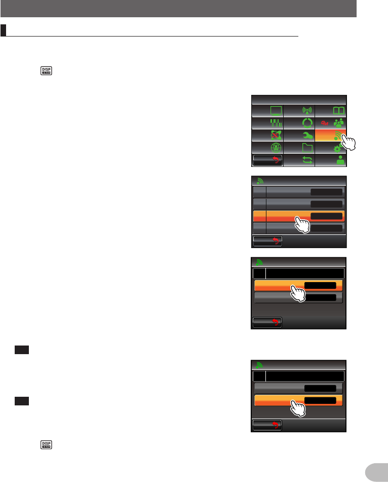
1 Press for one second or longer
The set-up menu will be displayed.
2 Touch [DATA]
$#%-
$#%-
6:4:
5'672/'07
4'5'6
%.10'
%10(+)9Ჰ4'5
5%#0
&+52.#;
5+) 0#.+0)
#245 126+10
5&%#4&
/'/14;
#
%#..5+) 0
3 Touch [3DATASPEED]
The screen for the detailed settings will be displayed.
Ż
Ż
Ż
#$#0&5'.'%6
%1/21465'66+0)
#52''&
Ჹ
Ჺ
Ż
#537'.%*
#
$#%-
$#%-
4 Touch [APRS] to select the packet communication
speed
The setting will switch between “1200 bps” and “9600
bps” each time it is touched.
1200 bps: Sets the speed as AFSK 1200 bps packet.
9600 bps: Sets the speed as GMSK 9600 bps
packet.
Tip Factory default value: 1200 bps
$#%-
$#%-
#52''&
#
#245
#
DRU
DRU
5 Touch [DATA] to select the data communication
speed
Repeat Step 4 to set the data communication speed.
Tip Factory default value: 1200 bps
$#%-
$#%-
#52''&
#
#245
#
DRU
DRU
6 Press for one second or longer
The baud rate of the APRS and data communication will be set and the display will
return to the previous screen.
Application for FCC / IC
FCC ID: K6620345X40 / IC: 511B-20345X40
198
Customize Menu Settings and User Preferences
UsingtheSet-upMenu
Settingtheoutputconditionofthesquelchdetectionandsquelchterminal
The squelch detection condition during APRS (internal modem) operation and squelch
terminal output condition of the data communication (when using the [DATA] jack at the
back of the main body) can be set.
1 Press for one second or longer
The set-up menu will be displayed.
2 Touch [DATA]
$#%-
$#%-
6:4:
5'672/'07
4'5'6
%.10'
%10(+)9Ჰ4'5
5%#0
&+52.#;
5+) 0#.+0)
#245 126+10
5&%#4&
/'/14;
#
%#..5+) 0
3 Touch [4DATASQUELCH]
The screen for the detailed settings will be displayed.
Ż
Ż
Ż
#$#0&5'.'%6
%1/21465'66+0)
#52''&
Ჹ
Ჺ
Ż
#537'.%*
#
$#%-
$#%-
4 Touch [APRS] to select the squelch detection
condition during APRS operation using the internal
modem
The setting switches between “RX BAND” and “TX/
RX BAND” each time it is touched.
RX BAND: Transmission is not possible when the
receive band squelch is open.
TX/RX BAND: Transmission is not possible when
either the receive band or transmit
band squelch is open.
Tip Factory default value: RX BAND
$#%-
$#%-
#537'.%*
#
#245
#
4:$#0&
4:$#0&
6: 10
5 Touch [DATA] to select the output condition (during
reception) related to the squelch terminal inside the
[DATA] jack
The setting switches between “RX BAND” and “TX/
RX BAND” each time it is touched.
RX BAND: The SQL terminal becomes active when
the receive band squelch is open.
TX/RX BAND: The SQL terminal becomes active
when either the receive band or
transmit band squelch is open.
Tip Factory default value: RX BAND
$#%-
$#%-
#537'.%*
#
#245
#
4:$#0&
4:$#0&
6: 10
Application for FCC / IC
FCC ID: K6620345X40 / IC: 511B-20345X40
199
Customize Menu Settings and User Preferences
UsingtheSet-upMenu
6 Touch [TX] to select the output condition (during
transmission) related to the squelch terminal inside
the [DATA] jack
Each time this is touched, the setting will switch
between “ON” and “OFF”.
ON: The SQL terminal becomes active during
transmission.
OFF: The SQL terminal does not become active
during transmission.
• The action to be taken when the reception band
specified using [DATA] under [2DATABAND
SELECT] in the DATA set-up menu is ready to
transmit is set here.
• When this is set to ON, transmission of external
devices such as TNC can be suppressed during
transmission.
Tip Factory default value: ON
$#%-
$#%-
#537'.%*
#
#245
#
4:$#0&
4:$#0&
6: 10
7 Press for one second or longer
The APRS and data communication squelch will be set and the display will return to
the previous screen.
APRSfunctionsettings
The APRS function of the radio is a data communication system for data such as
messages and station position using the APRS format.
Refer to the separate Operating Manual APRS Edition for details (download the manual
from the YAESU website).
Micro-SDcardsettings
Writingsettingstothemicro-SDcard
Using a micro-SD card, the memory channels registered in the radio and the settings in
the set-up menu can be copied to another FTM-400XDR/DE.
The settings saved in the micro-SD card can also be downloaded into the radio.
Refer to “Copying the Radio Data to another transceiver” ( P.151) for details.
Application for FCC / IC
FCC ID: K6620345X40 / IC: 511B-20345X40
200
Customize Menu Settings and User Preferences
UsingtheSet-upMenu
WritinggroupIDstothemicro-SDcard
The group ID information registered in the radio can be written to a micro-SD card.
The group ID information saved in the micro-SD card can also be downloaded into the
radio.
Refer to the separate Operating Manual GM Edition for further details (download the
operating manual from the YAESU website).
Initializingthemicro-SDcard
Initialize the memory card when using a new micro-SD card.
Refer to “Initializing the micro-SD card” ( P.35) for details.
Optionaldevicesettings
Settingtheimageoftheconnectedspeakermicrophonewithcamera
The image size and quality when taking pictures with the connected speaker
microphone with a camera (MH-85A11U) can be set.
1 Press for one second or longer
The set-up menu will be displayed.
2 Touch [OPTION]
$#%-
$#%-
6:4:
5'672/'07
4'5'6
%.10'
%10(+)9Ჰ4'5
5%#0
&+52.#;
5+) 0#.+0)
#245 126+10
5&%#4&
/'/14;
#
%#..5+) 0
3 Touch [1USBCAMERA]
The screen for setting the image will be displayed.
• PICTURE SIZE: Sets the size of the picture to be
taken.
• PICTURE QUALITY: Sets the quality of the picture
to be taken.
$#%-
$#%-
81+%'/'/14;
126+10
$ᲴWGVQQVJᲺ
Ż
75$%#/'4#ᲹŻ
Ż
4 Touch [PICTURESIZE] to set the picture size
The setting changes between “160✽120” and
“320✽240” each time it is touched.
Tip • Factory default value: 320✽240 (unit: pixel)
• It takes about 30 seconds to sending a picture in the
size of 320✽240 to other transceivers.
$#%-
$#%-
2+%674'37#.+6;
2+%674'5+<'
014/#.
75$%#/'4#Ჹ
126+10
ᲸᶤᲸ
Application for FCC / IC
FCC ID: K6620345X40 / IC: 511B-20345X40