Yaesu Musen 20345X40 AMATEUR RADIO WITH SCANNING RECEIVER User Manual OM
Yaesu Musen Co., Ltd. AMATEUR RADIO WITH SCANNING RECEIVER OM
Contents
- 1. User Manual
- 2. User Manual 1
- 3. User Manual 2
- 4. User Manual 3
- 5. User Manual 4
- 6. User Manual 5
- 7. User Manual 6
- 8. User Manual 7
- 9. User Manual 8
- 10. User Manual 9
- 11. User Manual 10
- 12. User Manual 11
- 13. User Manual 12
- 14. User Manual 13
- 15. User Manual 14
- 16. User Manual 15
- 17. User Manual 16
- 18. User Manual 17
- 19. User Manual 18
- 20. User Manual 19
- 21. User Manual 20
- 22. User Manual 21
User Manual 21
201
Customize Menu Settings and User Preferences
UsingtheSet-upMenu
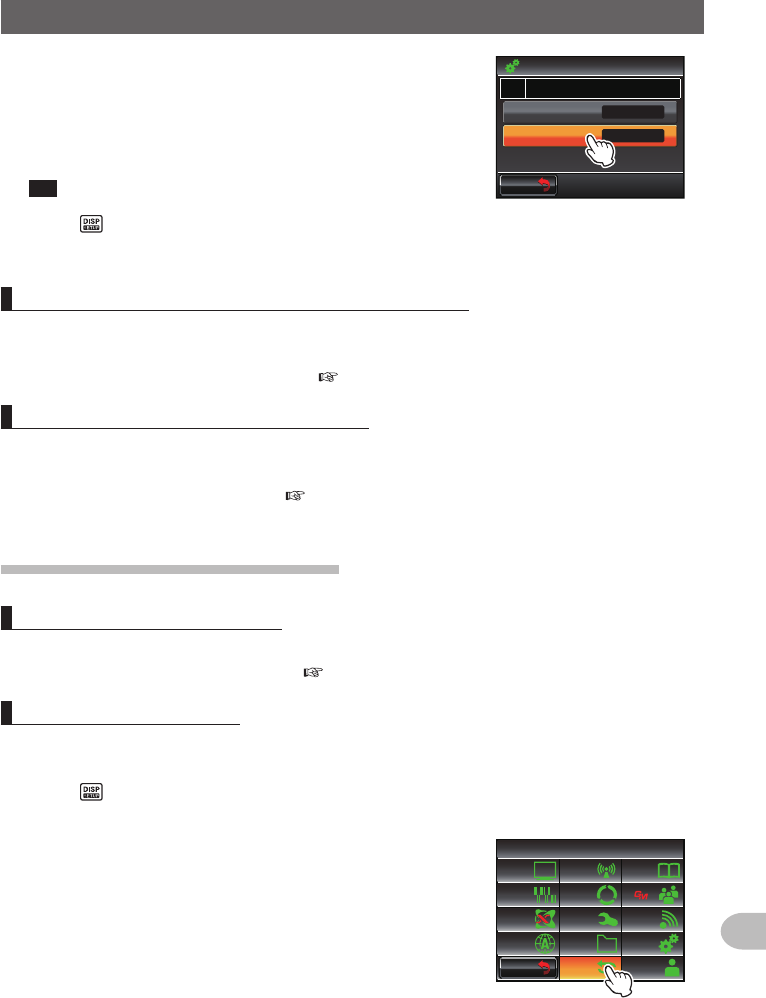
5 Touch [PICTUREQUALITY] to set the picture quality
The setting will change in the following order each
time it is touched.
“LOW (low resolution)” → “NORMAL” → “HIGH (high
resolution)”
Tip Factory default value: NORMAL
$#%-
$#%-
2+%674'37#.+6;
2+%674'5+<'
014/#.
75$%#/'4#Ჹ
126+10
ᲸᶤᲸ
6 Press for one second or longer
The camera image will be set and the display will return to the previous screen.
SettingtheoperationoftheBluetoothheadset
By mounting the Bluetooth unit to the radio and using a Bluetooth headset, audio can be
received and sent wirelessly.
Refer to “Using the Bluetooth headset” ( P.134) for details.
Settingthevoicememoryoperation
By mounting the voice guide unit to the radio, audio that is received or picked up by the
microphone can be recorded and then played back or erased later.
Refer to “Using the voice memory” ( P.146) for details.
Initializationandsavingsettings
Reconfiguringthesettings
The settings and memory of the radio can be returned to the default factory settings.
Refer to “Reconfiguring the Settings” ( P.61) for details.
Registeringthepreset
Current settings such as the frequency and memory channels can be registered in a
single preset.
1 Press for one second or longer
The set-up menu will be displayed.
2 Touch [RESET/CLONE]
$#%-
$#%-
6:4:
5'672/'07
4'5'6
%.10'
%10(+)9Ჰ4'5
5%#0
&+52.#;
5+) 0#.+0)
#245 126+10
5&%#4&
/'/14;
#
%#..5+) 0
Application for FCC / IC
FCC ID: K6620345X40 / IC: 511B-20345X40
202
Customize Menu Settings and User Preferences
UsingtheSet-upMenu
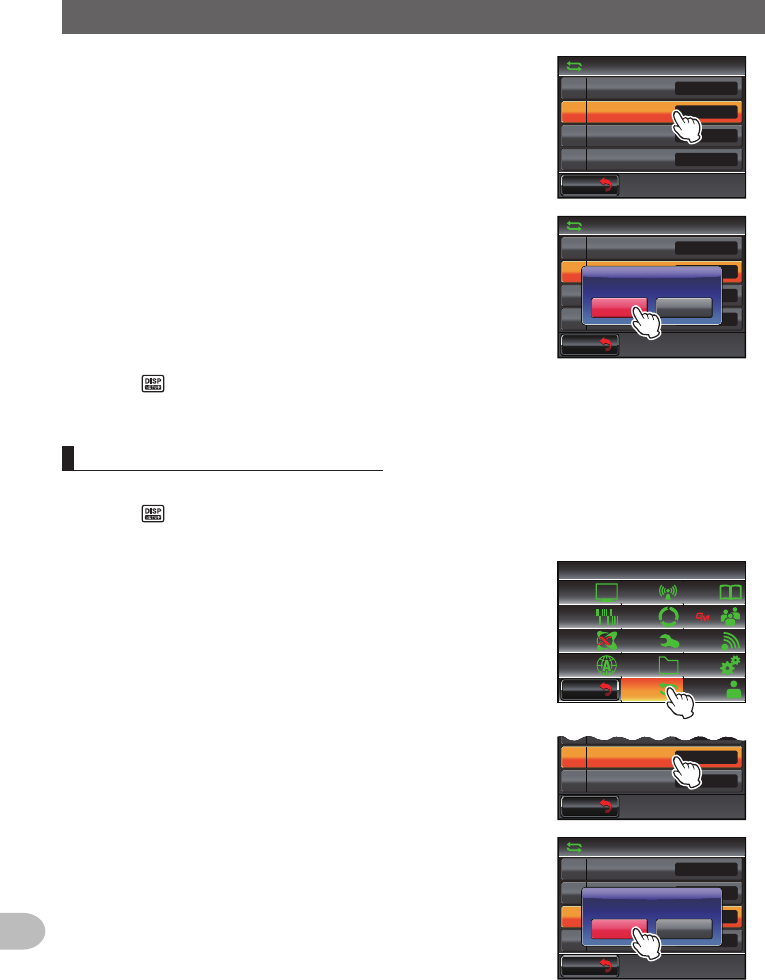
3 Touch [2PRESET]
The screen for confirming the preset registration will
be displayed.
$#%-
$#%-
4'5'6%.10'
Ჹ
Ჺ
(#%614;4'5'6
24'5'6
4'%#..24'5'6
/'/%*4'5'6
Ż
Ż
Ż
Ż
4 Touch [OK?]
The preset will be registered.
When canceling the registration, touch [Cancel].
$#%-
$#%-
4'5'6%.10'
Ჹ
Ჺ
(#%614;4'5'6
24'5'6
4'%#..24'5'6
/'/%*4'5'6
Ż
Ż
Ż
Ż
%CPEGᲴ1-!
24'5'6
5 Press for one second or longer
The display will return to the previous screen.
Recallingtheregisteredpreset
The registered preset can be recalled from the set-up menu.
1 Press for one second or longer
The set-up menu will be displayed.
2 Touch [RESET/CLONE]
$#%-
$#%-
6:4:
5'672/'07
4'5'6
%.10'
%10(+)9Ჰ4'5
5%#0
&+52.#;
5+) 0#.+0)
#245 126+10
5&%#4&
/'/14;
#
%#..5+) 0
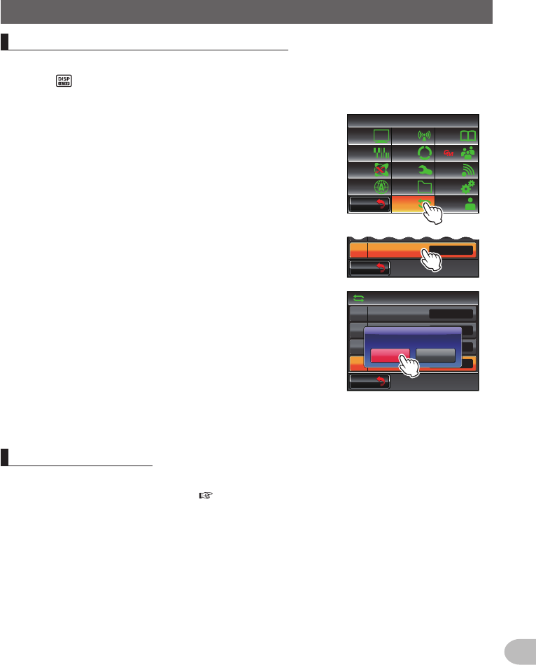
3 Touch [3RECALLPRESET]
The screen for confirming the recall of the registered
preset will be displayed.
$#%-
$#%-
Ჺ
24'5'6
4'%#..24'5'6
/'/%*4'5'6
Ż
Ż
Ż
4 Touch [OK?]
The registered preset will be recalled and the display
will return to the previous screen.
When canceling the recall, touch [Cancel].
$#%-
$#%-
4'5'6%.10'
Ჹ
Ჺ
(#%614;4'5'6
24'5'6
4'%#..24'5'6
/'/%*4'5'6
Ż
Ż
Ż
Ż
%CPEGᲴ1-!
4'%#..24'5'6
Application for FCC / IC
FCC ID: K6620345X40 / IC: 511B-20345X40
203
Customize Menu Settings and User Preferences
UsingtheSet-upMenu
Sortingtheregisteredmemorychannels
The memory channels registered in the radio can be sorted in the ascending order.
1 Press for one second or longer
The set-up menu will be displayed.
2 Touch [RESET/CLONE]
$#%-
$#%-
6:4:
5'672/'07
4'5'6
%.10'
%10(+)9Ჰ4'5
5%#0
&+52.#;
5+) 0#.+0)
#245 126+10
5&%#4&
/'/14;
#
%#..5+) 0
3 Touch [5MEMCHSORT]
The screen for confirming the sorting of the memory
channels will be displayed.
$#%-
$#%-
Ჽ
/'/%*4'5'6
/'/%*5146
Ż
Ż
4 Touch [OK?]
The memory channels will be sorted starting from the
lowest frequencies.
When canceling the sorting, touch [Cancel].
$#%-
$#%-
4'5'6%.10'
Ჺ
Ჽ
24'5'6
4'%#..24'5'6
/'/%*4'5'6
/'/%*5146
Ż
Ż
Ż
Ż
%CPEGᲴ1-!
/'/14;%*5146
5 The radio will start up again
The power will be switched off once and then it will be switched on automatically.
Copyingsaveddata
All the data saved in the radio can be copied directly to another FTM-400XDR/DE.
Refer to “Using the clone function” ( P.153) for details.
Application for FCC / IC
FCC ID: K6620345X40 / IC: 511B-20345X40
204
Customize Menu Settings and User Preferences
UsingtheSet-upMenu
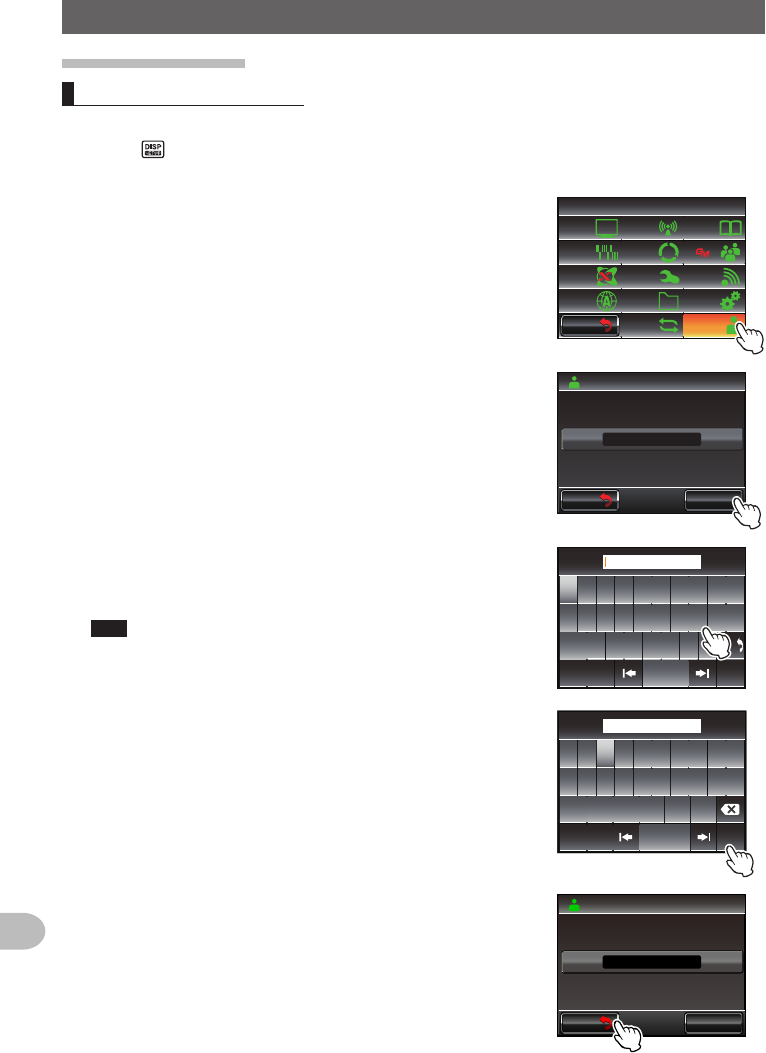
Callsignsettings
Changingthecallsign
You can change your own call sign set in the radio.
1 Press for one second or longer
The set-up menu will be displayed.
2 Touch [CALLSIGN]
The current call sign will be displayed.
$#%-
$#%-
6:4:
5'672/'07
4'5'6
%.10'
%10(+)9Ჰ4'5
5%#0
&+52.#;
5+) 0#.+0)
#245 126+10
5&%#4&
/'/14;
#
%#..5+) 0
3 Touch [CHANGE]
The character input screen will be displayed.
$#%-
$#%-
%*#0)'
%#..5+)0
$(ᲹᲹ Ჺ
;3,
4 Touch a character key
The touched character will be displayed at the top of
the screen.
Tips • Up to 10 characters of alphabets, numerics, and a
hyphen can be entered.
• Refer to Page 23 on how to operate the character input
screen.
39'46; 7 +12
#5&()*,-.
<:%8$0/
#$% 5RCEG
'06
@
ᲹᲺ
$#%-
$(ᲹᲹ Ჺ
;
3,
5 Touch [ENT]
The new call sign will be displayed.
ᲹᲺ
ᲽᲾᲿ᳀ ᳁ ᳂
"
#$% 5RCEG
'06
%CPEGᲴ
!
@
ᲹᲺ
4.ᲹᲹ Ჺ
<
#,
6 Touch [BACK]
$#%-
$#%-
%*#0)'
%#..5+)0
4.ᲹᲹ Ჺ
<#,
Application for FCC / IC
FCC ID: K6620345X40 / IC: 511B-20345X40

205
Customize Menu Settings and User Preferences
UsingtheSet-upMenu
7 Press for one second or longer
The call sign will be set and the display will return to the previous screen.
Application for FCC / IC
FCC ID: K6620345X40 / IC: 511B-20345X40
206
Appendix
Appendix
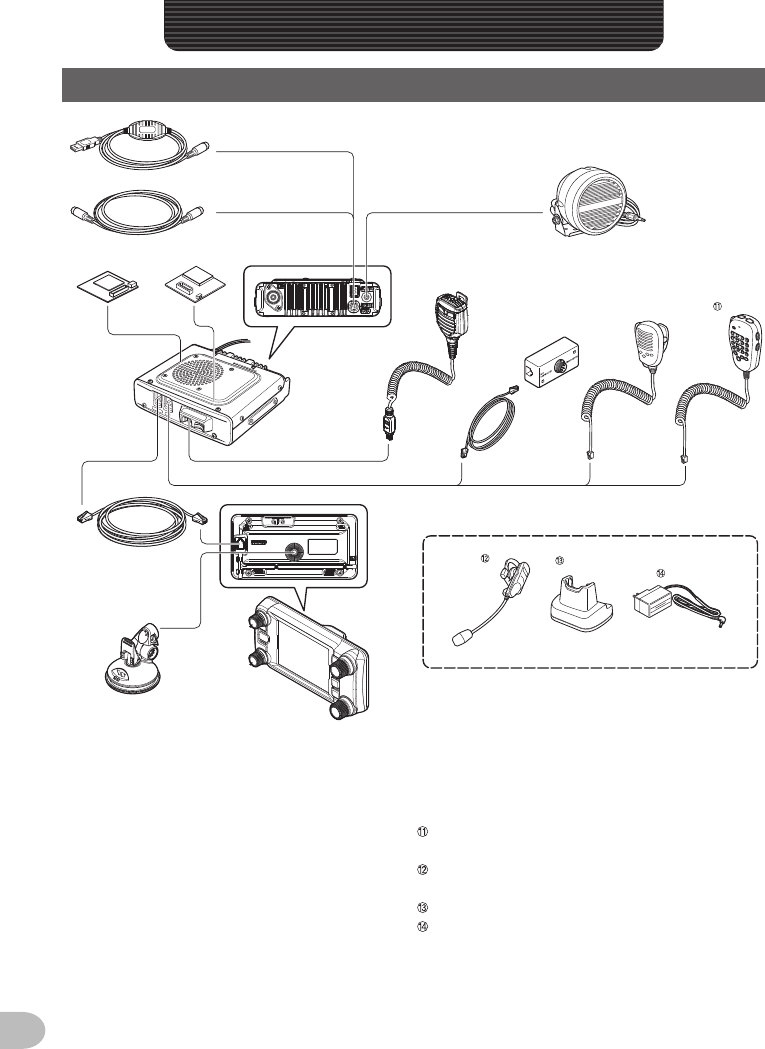
OptionsList
➀
➆
➇
➉
➈
➁
➂
➄
➅
➃
➀ PC connection cable (SCU-20)
*Same as the one provided
➁ Cloning cable (CT-166)
➂ Voice guide unit (FVS-2)
➃ Bluetooth unit (BU-2)
➄ Control cable (CT-162)
➅ Controller bracket (MMB-98)
➆ Water proof (equivalent to IP55) high power
external speaker (MLS-200-M10)
➇ Speaker microphone with camera
(MH-85A11U)
➈ Microphone extension kit (MEK-2)
➉ Hand Microphone (MH-42C6J)
DTMF Microphone (MH-48A6JA)
*Same as the one provided
Water proof Bluetooth headset (monaural)
(BH-2A)
Charging cradle for BH-2A (CD-40)
Battery charger for CD-40 (PA-46)
zData cable (CT-163): DIN 10 pin ←→ DIN 6 pin + Dsub 9 pin
zData cable (CT-164): DIN 10 pin ←→ DIN 6 pin
zData cable (CT-165): DIN 10 pin ←→ Dsub 9 pin
zData cable (CT-167): DIN 10 pin ←→ Split end (10 pin)
Application for FCC / IC
FCC ID: K6620345X40 / IC: 511B-20345X40
207
Appendix
Maintenance
Careandmaintenance
Turn the transceiver OFF before wiping away any dust and stains on the radio using
a dry and soft cloth. For stubborn stains, slightly moisten a soft cloth and wring it hard
before using it to wipe away the stains.
Caution Never use washing detergents and organic solvents (thinner, benzene etc.). This may
result in the paint peeling off or the cover being damaged.
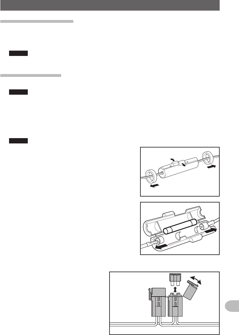
Replacingthefuse
Use ONLY the correct rating (15 A) replacement fuse in the DC cable fuse holder.
Caution When replacing the fuse, disconnect the power supply cable from the radio and from the
external DC power supply.
●ReplacingthefuseoftheDCpowersupplycable
1 Prepare a new fuse
Use a fuse with a rating of 15 A.
Caution Never use a fuse that is not of the specified rating.
2 Open the fuse holder as shown in the diagram on
the right
➀
➀
➁
3 Remove the broken fuse
4 Attach the new fuse
5 Close the fuse holder
European version
Application for FCC / IC
FCC ID: K6620345X40 / IC: 511B-20345X40

208
Appendix
Whenyouhavedifficulties...
Caution
Check the following before requesting for repair services.
Thereisnopower
zIs the external power supply connected correctly?
Connect the black wire to the negative (-) terminal and the red wire to the positive (+) terminal.
zIs the voltage and current capacity of the external power supply sufficient?
Check the voltage (13.8 V) and current capacity (20 A or above) of the external power supply.
zIs the fuse broken?
Replace the fuse.
Thereisnosound
zIs the squelch level or setting too high?
Adjust the squelch level when receiving weak signals.
zIs the volume low?
Increase the volume by turning the VOL knob in a clockwise direction.
zIs the tone squelch or DCS turned on?
When the tone squelch or DCS is turned on, no sound will be heard until signals containing the same
tone frequency, or DCS code that have been set are received.
zIs the external speaker connected?
Connect a speaker with an impedance of 4 to 16 Ω correctly.
zIs the Bluetooth headset in use?
Disable the use of the headset or use the set-up menu to allow sound to come from both the headset
and the main body speaker.
Thereisnotransmission
zIs the PTT switch pressed properly?
zIs the microphone connected correctly?
Plug the connector all the way into the MIC jack.
zIs the transmission frequency set to the amateur band?
Transmission outside the amateur band is not possible.
zIs the antenna or co-axial cable broken?
Replace the antenna or co-axial cable.
zIs the voltage of the external power supply normal?
When the voltage of the power supply drops during transmit, the transceiver may not work properly.
Use a stable DC power supply with a voltage of 13.8 V and a current capacity of 20 A.
Thekeysorknobswillnotoperate
zIs the lock function activated?
Cancel the lock by pressing the POWER / LOCK key.
Application for FCC / IC
FCC ID: K6620345X40 / IC: 511B-20345X40

209
Appendix
Whenyouhavedifficulties...
Aboutinternalspurioussignals
Certain frequency combinations of signals received simultaneously, may cause some effect on the receiver
mixer and IF circuits due to the high frequency of the internal oscillator.
However, this is not a malfunction (refer to the calculation formulas below: n is any integer).
Depending on the combination of the frequencies received at the same time, there may also be fluctuations
in the receiver sensitivity
zReception frequency = 12.288 MHz x n times zReception frequency = 15.6 MHz x n times
zReception frequency = 2.4576 MHz x n times zReception frequency = 6.1444 MHz x n times
zReception frequency = 11.1 MHz x n times zReception frequency = 18.432 MHz x n times
zUpper (Band A) frequency = (Lower (Band B) frequency ± 44.85 MHz) × n times
zLower (Band B) frequency = (Upper (Band A) frequency ± 47.25 MHz) × n times @ Upper band
(Band A) MODE = NFM
After-marketServices
Thewarrantyperiodis1yearor2yearsfromthedateofpurchase
The warranty certification is enclosed with the product. Breakdowns arising from normal use of the
product in accordance with the instructions in the operating manual shall be repaired free-of-charge
within a period of 1 year (USA, EXP version) or 2 years (European Version) from the date of purchase.
Keepthewarrantycertificateinasafelocation
When the warranty certificate is lost, failures which occur during the warranty period will be treated as
chargeable non-warranty claims.
A warranty certificate where necessary information such as the purchase date and the name of the retail
store have not been filled in will also be treated as void. Please ensure that the date of purchase and the
name of the retail store are filled in correctly in the warranty certificate.
Youmayalsocheckwithusforanynon-warrantyrepairs
We will repair at your expense if the functions can be maintained after the repair. Please check with the
retail store or Yaesu customer support for more information.
Keepthepackagingbox
When transporting this product for inspection and repair, use the original product packaging box to
prevent accidents and damages during the transport.
Application for FCC / IC
FCC ID: K6620345X40 / IC: 511B-20345X40

210
Appendix
Specification
●General
Frequencyrange : TX 144 - 146 MHz or 144 - 148 MHz
430 - 440 MHz or 430 - 450 MHz
:RX 108 - 137 MHz (Air Band)
137 - 174 MHz (144 MHz HAM)
174 - 400 MHz (GEN1)
400 - 480 MHz (430 MHz HAM)
480 - 999.99 MHz (GEN2)
Channelsteps : 5/6.25/8.33/10/12.5/15/20/25/50/100 kHz
(8.33 kHz : only for Air band)
EmissionType : F1D, F2D, F3E, F7W
Frequencystability : ±2.5 ppm −4°F to +140°F (−20°C to +60°C)
Antennaimpedance : 50 Ω
SupplyVoltage : Norminal 13.8 V DC, negative ground
Currentconsumption : 0.5 A (receive)
11 A (50 W TX, 144 MHz)
12 A (50 W TX, 430 MHz)
Operatingtemperature : −4°F to +140°F (−20°C to +60°C)
Casesize : Radio unit: 5.5" (W) × 1.6" (H) × 4.9" (D) (140 × 40 × 125 mm) w/o fan
Controller: 5.5" (W) × 2.8" (H) × 0.8" (D) (140 × 72 × 20 mm)
Weight(approx.) : 2.64 lbs (1.2 kg) with radio unit, controller, control cable
●Transmitter
RFpoweroutput : 50/20/5 W
Modulationtype : F1D, F2D, F3E : Variable Reactance Modulation
F7W : 4FSK (C4FM)
Spuriousemission : At least 60 dB below
Microphoneimpedance : About 2 kΩ
DATAterminalinputimpedance
: About 10 kΩ
Application for FCC / IC
FCC ID: K6620345X40 / IC: 511B-20345X40

211
Appendix
Ratings
●Receiver
Circuittype : Double conversion super-heterodyne
Intermediatefrequencies : A band:
1st : 47.25 MHz, 2nd :450 kHz
B band:
1st : 44.85 MHz, 2nd : 450 kHz
ReceiverSensitivity : 108 - 137 MHz (AM) 0.8μV typ for 10 dB SN
137 - 140 MHz (FM) 0.2μV for 12 dB SINAD
140 - 150MHz (FM) 0.2μV for 12 dB SINAD
150 - 174 MHz (FM) 0.25μV for 12 dB SINAD
174 - 222 MHz (FM) 0.3μV typ for 12 dB SINAD
222 - 300 MHz (FM) 0.25μV typ for 12 dB SINAD
300 - 336 MHz (AM) 0.8μV typ for 10 dB SINAD
336 - 420 MHz (FM) 0.25μV for 12 dB SINAD
420 - 470 MHz (FM) 0.2μV typ for 12 dB SINAD
470 - 520 MHz (FM) 0.2μV for 12 dB SINAD
800 - 900 MHz (FM) 0.4μV typ for 12 dB SINAD
900 - 999.99 MHz (FM) 0.8μV typ for 12 dB SINAD
Cellular blocked (USA only)
Digital mode
140 - 150 MHz (Digital) 0.19μV typ for BER 1%
420 - 470 MHz (Digital) 0.19μV typ for BER 1%
Squelchsensitivity : 0.16μV (144/430 MHz)
Selectivity : AM, FM 12 kHz/35 kHz (−6 dB/−60 dB)
AFoutput : 3 W (8 Ω, THD10%, 13.8 V) internal speaker
8 W (4 Ω, THD10%, 13.8 V) Optional MLS-200-M10
AFoutputimpedance : 4 - 16 Ω
Strengthofsecondaryradiowaves
:4 nW and below
Cautions
zRated values are at normal temperature and pressure.
zRatings and specifications are subject to change without notice.
●Symbolsplacedontheequipment
Direct current
Application for FCC / IC
FCC ID: K6620345X40 / IC: 511B-20345X40

212
Appendix
checking the route using a personal
computer .................................................. 90
clock shift of the CPU ............................. 188
clone function ......................................... 153
communicating ......................................... 49
communicating with specified partner
stations ................................................... 102
communication mode ............................... 45
compass panel
changing the direction .......................... 94
compass screen .........................20, 93, 172
COM port ................................................ 193
connecting the power supply .................... 30
connecting the radio ................................. 29
connecting to a personal computer ........ 155
CONTROL jack .................................. 15, 16
controller................................................... 14
connecting to the main body ................ 29
installing ............................................... 28
copying saved data ................................ 203
Copying the Radio Data to another
Transceiver ............................................. 151
copyrights ................................................... 4
countdown timer ......................................117
count down timer screen .......................... 22
CTCSS ................................................... 102
current location
registering ............................................ 95
Customize Menu Settings and User
Preferences ............................................ 163
D
data communication
baud rate ............................................ 197
operating band ................................... 196
data communication settings .................. 193
DATA jack ......................................... 16, 155
date and time.................................... 56, 183
display format ..................................... 184
DCS ........................................................ 104
using ................................................... 105
DCS code ............................................... 180
setting ................................................. 104
DCS transmission.................................... 111
DCS transmission / tone reception .......... 111
departure point
registering ............................................ 95
DIAL knob ........................................... 14, 15
Band A .................................................. 14
Band B ................................................. 15
digital code squelch ................................ 104
display background color........................ 172
display brightness............................. 58, 173
display contrast ...................................... 173
display method for my position ............... 178
display mode ............................................ 20
A
About internal spurious signals .............. 209
accessories .............................................. 13
after-market services .............................. 209
alphabet input screen ............................... 23
altitude
measuring ............................................ 90
altitude changes
erasing ................................................. 91
altitude display screen .............................. 21
AMS.................................................... 45, 46
AMS transmission mode ........................ 174
analog FM mode ...................................... 46
announce function
setting operation ................................. 149
antenna .................................................... 25
connecting ............................................ 29
install .................................................... 25
ANT terminal ............................................ 16
APO function ...........................................119
APRS
baud rate ............................................ 197
operating band ................................... 196
APRS function .......................................... 98
APRS function settings........................... 199
ARS .......................................................... 52
audio
erasing the recorded one ................... 148
muting .................................................. 48
recording and listening to ................... 144
recording the received one ................. 147
replaying the recorded one ................ 147
auto repeater shift .................................. 186
B
background color of the frequency display
area .......................................................... 60
backtrack function .............................. 93, 95
band scope ............................................... 47
band scope display width ....................... 172
band scope screen ................................... 19
beep volume ..................................... 54, 188
Bluetooth headset .................................. 134
identifying ........................................... 137
operation ............................................ 201
setting the operation ........................... 136
using ................................................... 139
Bluetooth unit
mounting ............................................ 134
C
call sign .................................................... 37
changing ............................................. 204
call sign settings ..................................... 204
car battery ................................................ 30
Index
Application for FCC / IC
FCC ID: K6620345X40 / IC: 511B-20345X40

213
Appendix
Index
DISP/SETUP key ..................................... 14
distance scale........................................... 91
DTMF ......................................................112
DTMF code
registering .................................. 112, 180
transmission method .......................... 180
transmitting
manually .......................................... 114
registered code ...............................113
DTMF function ......................................... 112
dual band screen ...................................... 19
dual receive .............................................. 81
restart condition .................................... 82
DWN ......................................................... 17
D/X key ..................................................... 14
E
external eevice connected...................... 155
external power supply equipment............. 32
external speaker ..................................... 162
EXT GPS jack .................................... 15, 84
EXT SP jack ..................................... 16, 162
F
FM mode .................................................. 51
F/MW key ................................................. 15
frequency step ........................................ 188
frequency steps ........................................ 41
FR mode................................................... 46
function menu screen ............................... 19
functions and configuration settings ....... 183
fuse
replacing ............................................. 207
G
gain........................................................... 50
geodetic reference system ............... 92, 192
GM function .............................................. 99
GM key ..................................................... 15
GPS .......................................................... 83
GPS function ............................................ 83
GPS log function ...................................... 89
GPS screen .............................................. 23
group monitor function settings .............. 183
H
home channel
changing the frequency ........................ 64
monitoring ............................................ 81
recalling ................................................ 63
I
initialization and saving settings ............. 201
inputting the character .............................. 23
installation location when used in a mobile
unit............................................................ 24
installing the radio .................................... 24
internal spurious intensity ....................... 209
interval for recording the GPS position
information.............................................. 192
L
lap timer...................................................116
lap timer screen ........................................ 22
latitude and longitude display screen ....... 88
Listening to the frequency voice
announcement........................................ 149
locking the knobs and switches ................ 55
M
main body ................................................. 16
installing ............................................... 27
maintenance ........................................... 207
memories to be skipped ........................... 77
memory
erasing ................................................. 65
naming ................................................. 66
recalling ................................................ 63
writing ................................................... 62
memory channel ....................................... 62
sorting ................................................ 203
memory channel settings ....................... 179
memory mode .......................................... 44
memory scan ............................................ 74
memory scan method ............................. 179
memory tag
display method ................................... 179
memory tag display .................................. 67
message
creating and sending .......................... 125
downloading ....................................... 124
forwarding .......................................... 132
receiving ............................................. 122
Registering standard messages ......... 128
replying to ........................................... 130
sending ....................................... 122, 125
sorting ................................................ 123
standard ............................................. 127
viewing ............................................... 122
MIC jack ................................................... 16
microphone
connecting ............................................ 29
microphone (MH-48A6JA) ........................ 17
micro-SD card .......................................... 33
copying data from ............................... 152
copying data to ................................... 151
initializing .............................................. 35
Initializing ........................................... 200
Application for FCC / IC
FCC ID: K6620345X40 / IC: 511B-20345X40

214
Appendix
Index
installing ............................................... 34
removing .............................................. 34
setting up .............................................. 33
writing group IDs to ............................ 200
writing settings to ............................... 199
micro-SD card settings ........................... 199
micro-SD card slot .................................... 16
modulation mode ...................................... 46
N
Narrow FM mode...................................... 47
notification of an incoming call using the bell
110, 181
numbers and symbols input screen.......... 23
O
operating band ......................................... 38
operating mode ........................................ 44
optional device settings .......................... 200
Optional receive Audio Record and
Playback ................................................. 144
options list .............................................. 206
other stations
registering the locations ....................... 96
P
packet communication............................ 158
setting the operation ........................... 160
pager function......................................... 106
activating ............................................ 108
pairing..................................................... 137
partner station information
pop-up time ........................................ 177
picture
downloading ....................................... 124
forwarding .......................................... 132
receiving ............................................. 122
replying to ........................................... 130
sending ....................................... 122, 125
sending the saved one ....................... 129
sorting ................................................ 123
taking .................................................. 141
taking with the camera attached to the
speaker microphone ........................... 140
viewing ............................................... 122
viewing the saved one ........................ 143
PIN code......................................... 137, 191
PMS.......................................................... 79
PMS memory channel .............................. 79
position information .................................. 87
displaying the current ........................... 87
displaying the partner station ............... 87
recording .............................................. 89
position information display screen ........ 172
position information screen ...................... 88
position information to the computer ...... 156
positioning using GPS .............................. 83
positioning using the external GPS device ...
84, 192
position of the destination......................... 97
power off ................................................... 36
automatic ............................................ 191
power supply/LOCK switch ...................... 14
preset
recalling .............................................. 202
registering .......................................... 201
program key of the microphone.............. 189
programmable key
assigning the WX function to ................ 71
programmable memory
writing into ............................................ 79
PTT ........................................................... 17
R
radio wave format ................................... 174
real-time navigation function .............. 93, 94
recalling a specified station .................... 108
receiving ................................................... 36
reception range
expanding ........................................... 190
reconfiguring the settings ................. 61, 201
registered trademarks ................................ 4
repeater .................................................... 52
repeater shift
direction .............................................. 186
width ................................................... 187
reset
erasing only the registered memory
channels ............................................... 61
restoring all settings ............................. 61
restoring the APRS settings ................. 61
reverse tone ............................................110
S
satellite capture status.............................. 86
saving the destination............................... 95
scanning direction .................................. 182
scanning function ..................................... 72
scanning method ...................................... 75
scanning stop ......................................... 183
scanning the programmable memories ... 79,
80
scan only the specified memory channels 76
scan settings .......................................... 182
screen....................................................... 18
screen display settings ........................... 171
Select the screen to be displayed .......... 171
sensitivity of the microphone ............ 50, 179
Application for FCC / IC
FCC ID: K6620345X40 / IC: 511B-20345X40

215
Appendix
Index
Setting the receive station code ............. 106
set-up menu
basic operations ................................. 163
list ....................................................... 164
using ................................................... 171
signal reception method ......................... 182
smart navigation function ......................... 93
snapshot function ................................... 140
speaker microphone with camera .......... 200
connecting .......................................... 140
specification............................................ 210
specified memories .................................. 75
specified stations
recalling .............................................. 180
split memory ............................................. 68
squelch code of the digital mode ............ 176
squelch detection ................................... 198
squelch level............................................. 39
squelch terminal ..................................... 198
squelch type
setting for transmission and reception
separately ........................................... 181
squelch type of the digital mode ............. 175
Standby Beep ......................................... 178
stopwatch function...................................115
sub-band mute ....................................... 179
T
Taking Pictures with the optional Camera
(Snapshot Function) ............................... 140
time display ............................................ 173
timer / clock screen .................................115
timer/clock screen .................................... 21
timer function ........................................... 115
time zone .......................................... 92, 185
TNC ........................................................ 158
Tone Calling.............................................. 53
tone frequency........................................ 180
setting ................................................. 102
tone signal settings................................. 180
tone squelch ........................................... 102
using ................................................... 103
tone transmission / DCS reception .......... 111
TOT function ........................................... 120
touch key ................................................ 121
touch panel ................................................. 4
touch panel display................................... 14
transmission time
limiting ................................................ 191
Transmit and receive settings ................ 174
transmit power .......................................... 50
transmitting ............................................... 49
transmitting the tone signal .................... 103
tuning the radio......................................... 40
turning the power on................................. 36
U
unit display ............................................. 191
UP ............................................................ 17
updating the firmware of the radio .......... 157
User Programmed Reverse CTCSS
Decoder ................................................... 110
user programmed reverse CTCSS tone . 180
V
V/D mode ................................................. 46
version of the DSP program ................... 178
VFO mode ................................................ 44
VFO scan ................................................. 72
voice guide unit
mounting ............................................ 144
voice memory ......................................... 146
operation ............................................ 201
setting the operation ........................... 146
VOL knob ................................................. 14
voltage display........................................ 173
volume ...................................................... 38
VOX ........................................................ 134
W
weather alert..................................... 71, 182
weather channels ..................................... 70
recalling ................................................ 71
When you have difficulties ...................... 208
WX function .............................................. 70
Application for FCC / IC
FCC ID: K6620345X40 / IC: 511B-20345X40

216
Appendix
1. Changes or modifications to this device not expressly approved by YAESU MUSEN could void the
user’s authorization to operate this device.
2. This device complies with part 15 of the FCC Rules. Operation is subject to the following two
conditions: (1) This device may not cause harmful interference, and (2) this device must accept any
interference including received, interference that may cause undesired operation.
3. The scanning receiver in this equipment is incapable of tuning, or readily being altered, by the User
to operate within the frequency bands allocated to the Domestic public Cellular Telecommunications
Service in Part 22.
Part 15.21: Changes or modifications to this device not expressly approved by YAESU MUSEN could
void the user’s authorization to operate this device.
DECLARATIONBYMANUFACTURER
The Scanner receiver is not a digital scanner and is incapable of being converted or modified to a
digital scanner receiver by any user.
WARNING: MODIFICATION OF THIS DEVICE TO RECEIVE CELLULAR RADIOTELEPHONE
SERVICE SIGNALS IS PROHIBITED UNDER FCC RULES AND FEDERAL LAW.
Application for FCC / IC
FCC ID: K6620345X40 / IC: 511B-20345X40
217
Appendix
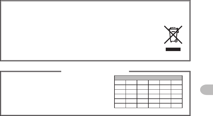
Disposal of your Electronic and Electric Equipment
Products with the symbol (crossed-out wheeled bin) cannot be disposed as house-
hold waste.
Electronic and Electric Equipment should be recycled at a facility capable
of handling these items and their waste by products.
In EU countries, please contact your local equipment supplier representa-
tive or service center for information about the waste collection system in
your country.
This transceiver works on frequencies which are
not generally permitted.
As for the actual usage, the user has to possess an
amateur radio licence.
Usage is allowed only in the frequency bands
which are allocated for amateur radios.
Attentionincaseofuse
Listofnationalcodes
AT BE BG CY CZ DE
DK ES EE FI FR GB
GR HR HU IE IT LT
LU LV MT NL PL PT
RO SK SI SE CH IS
LI NO – – – –
Application for FCC / IC
FCC ID: K6620345X40 / IC: 511B-20345X40

YAESU MUSEN CO., LTD.
Tennozu Parkside Building
2-5-8 Higashi-Shinagawa, Shinagawa-ku, Tokyo
140-0002 Japan
YAESU USA
6125 Phyllis Drive, Cypress, CA 90630, U.S.A.
YAESU UK
Unit 12, Sun Valley Business Park, Winnall Close
Winchester, Hampshire, SO23 0LB, U.K.
Printed in Japan
Copyright 2015
YAESU MUSEN CO., LTD.
All rights reserved.
No portion of this manual
may be reproduced
without the permission of
YAESU MUSEN CO., LTD.
1508-EM
Application for FCC / IC
FCC ID: K6620345X40 / IC: 511B-20345X40