Yaesu Musen 20345X40 AMATEUR RADIO WITH SCANNING RECEIVER User Manual OM
Yaesu Musen Co., Ltd. AMATEUR RADIO WITH SCANNING RECEIVER OM
Contents
- 1. User Manual
- 2. User Manual 1
- 3. User Manual 2
- 4. User Manual 3
- 5. User Manual 4
- 6. User Manual 5
- 7. User Manual 6
- 8. User Manual 7
- 9. User Manual 8
- 10. User Manual 9
- 11. User Manual 10
- 12. User Manual 11
- 13. User Manual 12
- 14. User Manual 13
- 15. User Manual 14
- 16. User Manual 15
- 17. User Manual 16
- 18. User Manual 17
- 19. User Manual 18
- 20. User Manual 19
- 21. User Manual 20
- 22. User Manual 21
User Manual 8
80
Scanning
SignalSearch
10 Press
The display will return to the previous screen, and the memorized frequency and
memory channel number will be displayed.
LowerfrequencyP1L
2Ჹ.
/76'
5%12'
/8 53.
ᲺᲸᲸ
ᲸᲸ
8(1
ᲹᲽᲾ
UpperfrequencyP1U
/76'
5%12'
/8 53.
2Ჹ7
ᲿᲸᲸ
ᲸᲸ
8(1
ᲹᲽᲾ
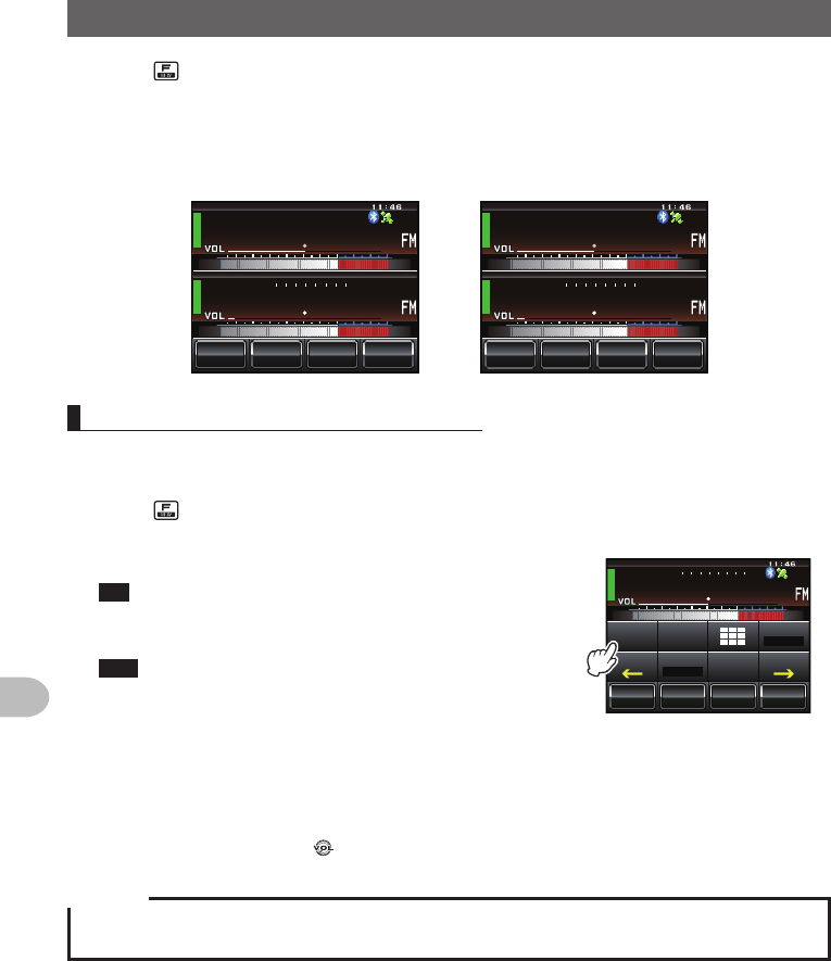
Scanningtheprogrammablememory
1 Switch to the memory mode
2 Recall the PMS memory of the upper frequency or lower frequency
3 Press briefly
The function menu will be displayed.
4 Touch [SCAN]
Tip When [SCAN] is not displayed in the function menu,
touch [BACK] or [FWD] to switch the menu.
The programmable memory scan will be started.
Tips • The scan can also be started by pressing the [UP] or
[DWN] button on the microphone for one second or
longer.
ᲸᲸ
᳀ᲾᲸ
ᲽᲸ
ᲽᲸᲸ61-;1Ჺ
/76'
5%12'
/8 53.
2Ჹ.
Ჺ
5-+25'.
1((
&9
6Z294
*+
5%#0 4'8
(9&$#%-
• When a signal is received, the scanning stops for three seconds and then the scanning starts
again.
• To stop the scanning, either touch [SCAN] or press the microphone [PTT] button (the radio
will not transmit in this case).
• The squelch level may be adjusted using the following procedure during scanning.
Touch [SQL] → Turn
Caution
When the upper and lower frequencies are not set correctly, the programmable memory scan will not
work.
Application for FCC / IC
FCC ID: K6620345X40 / IC: 511B-20345X40
81
Scanning
MonitoringtheHomeChannel
This radio is equipped with a dual receive function (also known as dual watch (DW))
which checks for a signal on the home channel approximately every three seconds
while monitoring or scanning. If a signal is detected, the home channel is received for
five seconds, and then monitoring or scanning with dual receive is resumed.
Example:Whencheckingthehomechannelwhilereceiving“145.500MHz”
ᲸᲸ
᳀ᲾᲸ
ᲽᲸᲸ61-;1Ჺ
/76'
5%12'
/853.
8(1
ᲹᲽᲽ
Reception frequency
ᲸᲸ
᳀ᲾᲸ
ᲽᲸ
ᲽᲸᲸ61-;1Ჺ
/76'
5%12'
8 53.
ᲸᲹ Ჽ
*1/'
/
5-+25'.
1((
&9
6Z294
*+
5%#0 4'8
(9&$#%-
Monitor the home channel at
intervals of about three seconds.
When the home channel is busy,
the radio receives the signal for
five seconds and then starts the
dual receive again.
Caution
When shipped from the factory, the default frequency in the home channel of 144 MHz Band is set
to 144.000 MHz while the default frequency in the home channel of 430 MHz Band is set to 430.000
MHz. These channels may be changed to a favorite operating frequency ( P.64).
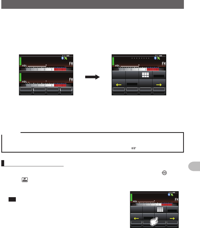
Usingthedualreceive
1 Tune in to the memory channel or a desired VFO receive frequency using
2 Press briefly
The function menu will be displayed.
3 Touch [DW]
Tip When [DW] is not displayed in the function menu, touch
[BACK] or [FWD] to switch the menu.
Dual receive will start, and the home channel
frequency will be received approximately every three
seconds.
ᲸᲸ
᳀ᲾᲸ
ᲽᲸ
ᲽᲸᲸ61-;1Ჺ
/76'
5%12'
53./
8(1
ᲹᲽᲽ
8
5-+25'.
1((
&9
6Z294
*+
5%#0 4'8
(9&$#%-
When a signal is detected on the home channel, it will continue to be received until
the signal disappears.
●Tocancelthedualreceive
Touch [DW] again.
Application for FCC / IC
FCC ID: K6620345X40 / IC: 511B-20345X40
82
Scanning
MonitoringtheHomeChannel
Settingtherestartconditionofdualreceive
The dual receive restart condition when the home channel signal is detected can be
selected from the following two ways.
(1) Restarts dual receive after five seconds have passed (AUTO).
(2) Stops dual receive and continue to receive the home channel (HOLD).
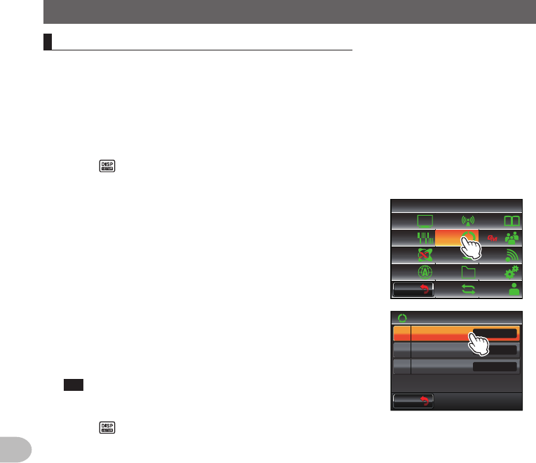
1 Press for one second or longer
The set-up menu will be displayed.
2 Touch [SCAN]
The menu list will be displayed.
$#%-
$#%-
6:4:
5'672/'07
4'5'6
%.10'
%10(+)9Ჰ4'5
5%#0
&+52.#;
5+) 0#.+0)
#245 126+10
5&%#4&
/'/14;
#
%#..5+) 0
3 Touch [1DUALWATCHSTOP] to select the restart
condition
The setting switches between “AUTO” and “HOLD”
each time it is touched.
Tip Factory default value: AUTO
$#%-
$#%-
UGE
5%#0
5%#04'57/'
5%#0&+4'%6+10
Ჹ
Ჺ
#761
&7#.9#6%*5612
72
4 Press for one second or longer
The dual receive restart condition will be set and the display will return to the
previous screen.
Application for FCC / IC
FCC ID: K6620345X40 / IC: 511B-20345X40
83
Using the GPS Function
This radio is equipped with an internal GPS reception unit to receive and display the
position information at all times. The position information can be used as in the following
example.
Save the position information in the memory and use it for navigation purposes
Refer to “Using the backtrack function” (Page 95)
Save the stations with frequent communications and checks whether they are
within the sphere of communications
Refer to the separate “Operating Manual GM Edition”
Exchange position information and messages through data communications with
other stations
Refer to the separate “Operating Manual APRS Edition”
WhatisGPS?
GPS or Global Positioning System is a satellite location system to determine the current
position on earth. It is a military system developed by the US Department of Defense
with approximately 30 GPS satellites circumnavigating the earth at an altitude of about
20,000 km, When signals from three or more satellites in space are received, the
current position information (longitude, latitude, altitude etc.) may be determined within
an accuracy of several meters. The accurate time can also be received from the atomic
clock built into the GPS satellite.
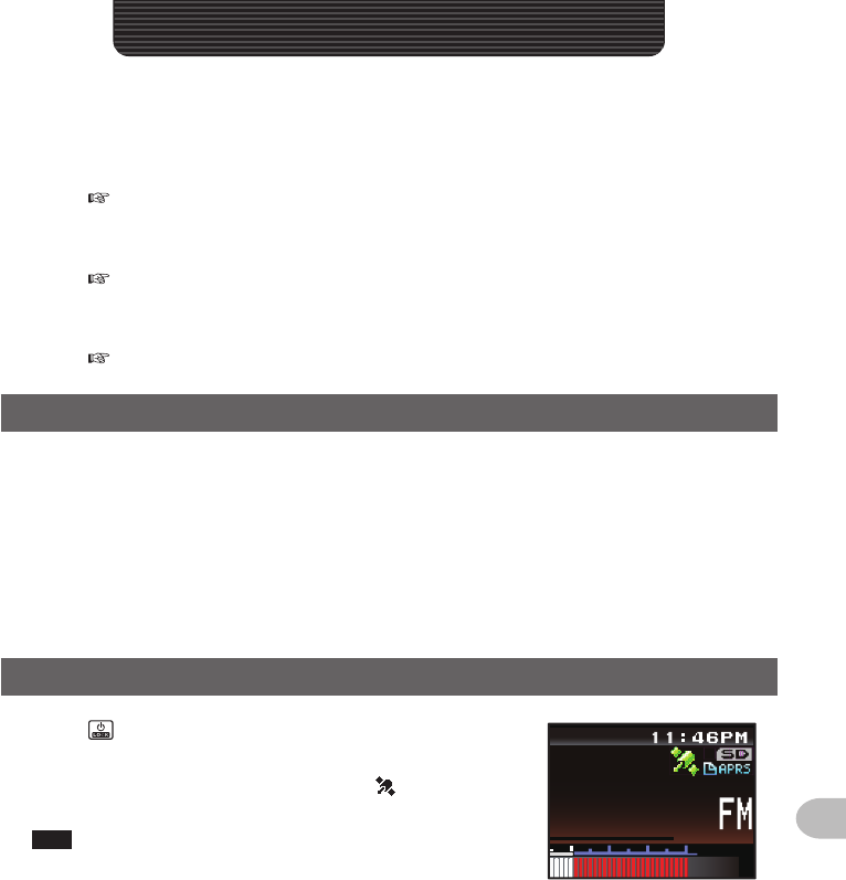
PositioningUsingGPS
1 Press for one second or longer to switch on the
power
The satellite search will begin and the “ ” icon will
be displayed at the top right of the screen.
Tips • It may take several minutes to capture the satellites.
• When three or more satellites cannot be captured, the
icon display will disappear. In this case, positioning is
not possible and the position information cannot be
used.
ᲸᲸ
#/#
UsingtheGPSFunction
Application for FCC / IC
FCC ID: K6620345X40 / IC: 511B-20345X40
84
Using the GPS Function
PositioningUsingGPS
AboutGPSpositioning
Positioning refers to the calculation of one’s own position from the satellites orbit information and
the transmission time of the radio waves. Positioning requires that three or more satellites be
acquired. When positioning cannot be carried out properly, move to an open space as far away
from buildings as possible and where there are fewer obstructions.
●Abouttheerror
Depending on the surrounding environment of the receiver location, an error of several hundred
meters may occur. Although positioning is possible using only three satellites, depending on the
positioning conditions, the positioning accuracy may become worse, or may no longer be possible
under the following conditions:
• Between high rise buildings, narrow roads between buildings, indoors and under the shade of
buildings, below high voltage lines and underneath overhead structures, between trees and
shrubs such as in forests and woods, inside tunnels and underground, when used behind a solar-
energy reflecting glass, locations where a strong magnetic field occurs
●Whennotusingtheradioforalongperiodoftime
When using the GPS function for the first time after purchasing the FTM-400XDR/DE transceiver,
and when turning it on after It has not been used for a long period time, positioning may take
several minutes in order to search for the satellites. Also, when using the device again several
hours after switching off the power, positioning may take several minutes in order to search for the
satellites.
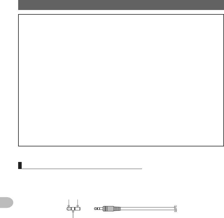
PositioningusinganexternalGPSdevice
Commercial GPS receive devices can also be connected to the [EXT GPS] jack on the
side of the controller.
The [EXT GPS] plug connector is illustrated below.
➀➂
➁
➀ TXD (serial data output [transceiver → external device])
➁ RXD (serial data input [transceiver ← external device])
➂ GND
Application for FCC / IC
FCC ID: K6620345X40 / IC: 511B-20345X40
85
Using the GPS Function
PositioningUsingGPS
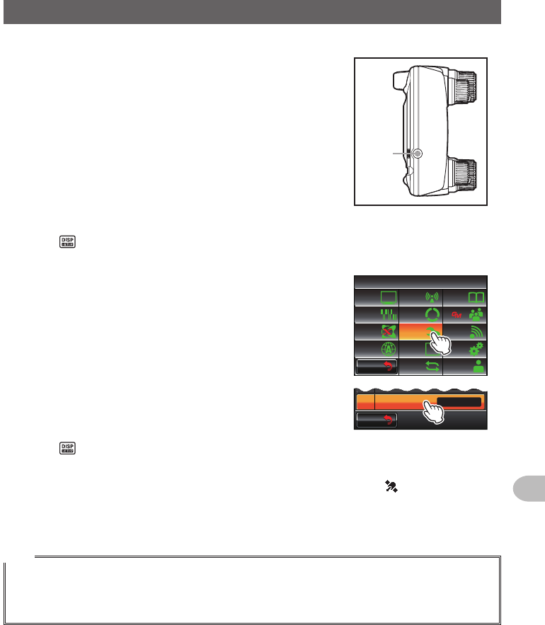
1 Switch off the power to the radio
2 Plug the connector of the external device into the
[EXT GPS] jack on the side of the controller unit.
EXT
GPS
3 Switch on the power to the radio
4 Press for one second or longer
The set-up menu will be displayed.
5 Touch [CONFIG]
The menu list will be displayed.
$#%-
$#%-
6:4:
5'672/'07
4'5'6
%.10'
%10(+)9Ჰ4'5
5%#0
&+52.#;
5+) 0#.+0)
#245 126+10
5&%#4&
/'/14;
#
%#..5+) 0
6 Touch [17GPSDEVICE] to select “EXTERNAL”
Each time this symbol is touched, the setting will
switch between “INTERNAL” and “EXTERNAL”.
$#%-
$#%-
)25C/
)25&'8+%' +06'40#.
9)5
ᲾᲹ
ᲿᲹ
7 Press for one second or longer
Return to the previous screen.
When the external device captures three or more satellites, the “ ” icon will be
displayed on the top right of the screen.
Tips
• When connecting to an external GPS device, refer to the operating manual of the connected device
as well.
• When using an external GPS device, keep the radio away from the external GPS device.
• When using an external GPS device, the data from the in-built GPS will become invalid.
Application for FCC / IC
FCC ID: K6620345X40 / IC: 511B-20345X40
86
Using the GPS Function
PositioningUsingGPS
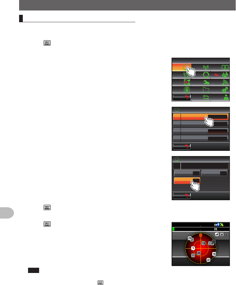
Checkingthesatellite capture status
The satellites acquired at the current location and the strengths of the signals can be
observed on the radar-like screen.
1 Press for one second or longer
The set-up menu will be displayed.
2 Touch [DISPLAY]
The menu list will be displayed.
$#%-
$#%-
6:4:
5'672/'07
4'5'6
%.10'
%10(+)9Ჰ4'5
5%#0
&+52.#;
5+) 0#.+0)
#245 126+10
5&%#4&
/'/14;
#
%#..5+) 0
3 Touch [1DISPLAYSELECT]
The screen for setting the various screens on and off
will be displayed.
Ż
6#4)'6.1%#6+10
&+52.#;
&+52.#;5'.'%6
#0)'41
$#%-)4170&%1.14
%1/2#55
9+&'$#0&5%12'
Ჹ
Ჺ
$#%-
$#%-
4 Touch [GPSINFO] to select “ON”
Each time this symbol is touched, the setting will
switch between “OFF” and “ON”.
&+52.#;
)25+0(1
#.6+67&'((1
((1
((1
6+/'4%.1%-
&+52.#;5'.'%6Ჹ
$#%-
$#%-
5 Press for one second or longer
The display will return to the previous screen.
6 Press twice briefly
The radar-shaped GPS screen will be displayed
and the acquired GPS satellite number and signal
strength icon will be displayed.
The brighter the color of the icon, the stronger is the
signal strength.
Tips • When the Altitude display screen and Timer/Clock
screen are both “ON”, the screen will change in the
following order each time is pressed.
Normal frequency display → Compass/Lat&Lon display
screen → Altitude display screen → Timer/Clock screen
→ GPS screen
• When connecting an external GPS device, satellite
information may not be output depending on the GPS
device (in this case, the icon will not be displayed).
)25+0(1
Ჸ
ᲹᲽᲸᲸ
18(
18( Ჸ
ᲸᲸ
Application for FCC / IC
FCC ID: K6620345X40 / IC: 511B-20345X40
87
Using the GPS Function
PositioningUsingGPS
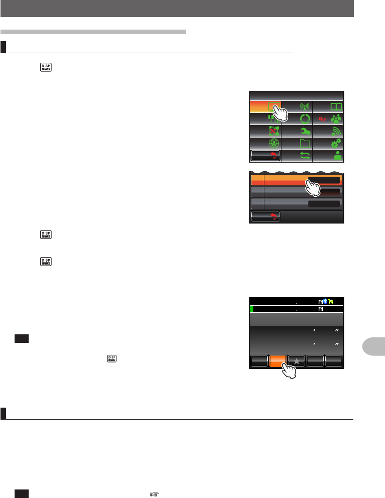
Displayingtheposition information
Displayingthecurrentpositioninformationofyourstation
1 Press for one second or longer
The set-up menu will be displayed.
2 Touch [DISPLAY]
The menu list will be displayed.
$#%-
$#%-
6:4:
5'672/'07
4'5'6
%.10'
%10(+)9Ჰ4'5
5%#0
&+52.#;
5+) 0#.+0)
#245 126+10
5&%#4&
/'/14;
#
%#..5+) 0
3 Touch [2TARGETLOCATION] to select “NUMERIC”
Each time this is touched, the setting will switch
between “COMPASS” and “NUMERIC”.
Ż
6#4)'6.1%#6+10
&+52.#;5'.'%6
#0)'41
$#%-)4170&%1.14
%1/2#55
9+&'$#0&5%12'
Ჹ
Ჺ
$#%-
$#%-
4 Press for one second or longer
The display will return to the previous screen.
5 Press briefly
The latitude and longitude display screen will be
displayed.
6 Touch [MY]
The latitude and longitude of your station will be
displayed in numerical figures.
Tip When the Altitude display screen and Timer/Clock screen
are both “ON”, the screen will change in the following
sequence each time is pressed.
Normal frequency display → Compass/Lat&Lon display
screen → Altitude display screen → Timer/Clock screen
→ GPS screen
ᲽᲢᲿᲺ0
Ჹ᳁ᲢᲽᲸᲺ'
␃␃␃␃
&+56#0%'.#6.10
/;
;4 .Ჺ
.Ჹ
Ჸ
ᲹᲽᲸᲸ18(
18( Ჸ
ᲸᲸ
MO
Displayingthepositioninformationofthepartnerstationinthedigitalmode
In the C4FM digital V/D mode, the position and direction to the partner station can be
displayed in real time during the communication. The position information obtained from
the GPS is transmitted at the same time as the voice signal.
1 Switch the communication mode to AMS (auto mode select function) or digital mode,
or activate the GM function
Tip Refer to “Using the GM function” ( P.99) on the basic method of using the GM function.
2 Switch to the latitude and longitude display screen
3 Touch [YR]
The latitude and longitude of the partner station will be displayed in numerical
figures.
Application for FCC / IC
FCC ID: K6620345X40 / IC: 511B-20345X40
88
Using the GPS Function
PositioningUsingGPS
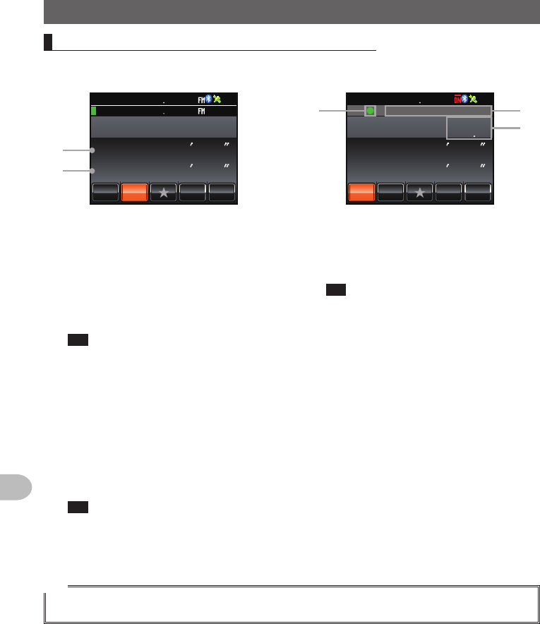
Explanationoftheposition information screen
Exampleofadisplayofyour
own station position
Exampleofadisplayofa
partner station position
81(
ᲽᲢᲿᲺ0
Ჹ᳁ᲢᲽᲸᲺ'
␃␃␃␃
&+56#0%'.#6.10
/;
;4 .Ჺ
.Ჹ
Ჸ1
8( ᲹᲽᲸᲸ
ᲸᲸᲸ
MO
➀
➁
ᲽᲢ᳀ᲹᲸ0
Ჹ᳁ᲢᲺᲺᲹ'
&+56#0%'.#6.10
/;
;4 .Ჺ
.Ჹ
Ჸ1
8( ᲹᲽᲸᲸ
MO
Ჹ
,#<4.Ჺ
ᲹᲹ
Ჺ
➂
➄
➃
➀ Latitude
Displayed as “X DD°MM’SS””
X: N (north latitude) / S (south latitude)
DD: 0 - 90 (degrees)
MM: 0 - 59 (minutes)
SS: 0 - 59 (seconds)
Example: N 35°37’ 23” (latitude 35 degrees
37 minutes & 23 seconds)
Tip The “DD°MM’SS”” and “DD°MM.
MM’” will switch each time the number
section is touched.
➁ Longitude
Displayed as “X DDD°MM’SS””
X: E (east longitude) / W (west longitude)
DDD: 0 - 180 (degrees)
MM: 0 - 59 (minutes)
SS: 0 - 59 (seconds)
Example: E 139°45’ 02” (east longitude 139
degrees 45 minutes 02 seconds)
Tip The “DDD°MM’SS”” and “DDD°MM.
MM’” will switch each time the number
section is touched.
➂ Position information status display
The status display will indicate that the
data received contains position information.
The status display will blink when the GM
function is activated.
Tip Refer to the separate Operating
Manual GM Edition for the details
on the GM function (download the
manual from the YAESU website).
➃ Partner station call sign and time of
receipt
➄ Distance to a partner station
Tip
Use [APRS] → [12APRSUNITS] in the set-up menu to change the display units of the various data.
Application for FCC / IC
FCC ID: K6620345X40 / IC: 511B-20345X40
89
Using the GPS Function
PositioningUsingGPS
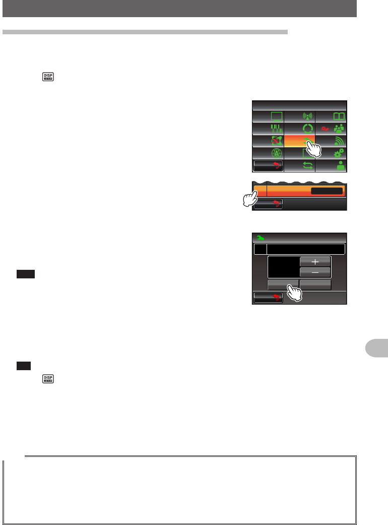
Recordingthepositioninformation(GPSlogfunction)
The position information of your own station can be recorded (saved) in a micro-SD card
on a regular basis.
1 Press for one second or longer
The set-up menu will be displayed.
2 Touch [CONFIG]
The menu list will be displayed.
$#%-
$#%-
6:4:
5'672/'07
4'5'6
%.10'
%10(+)9Ჰ4'5
5%#0
&+52.#;
5+) 0#.+0)
#245 126+10
5&%#4&
/'/14;
#
%#..5+) 0
3 Select [18GPSLOG] and touch the screen
The screen for selecting the recording interval and
switching the GPS log function ON and OFF will be
displayed.
$#%-
$#%-
+06'40 .#
1((
ᲹᲿ
Ჹ᳀
)25&'8+%'
)25.1)
4 Touch [ON]
The interval timing will be displayed in green
characters.
Tips • The position information will not be recorded when
“OFF” is selected.
• Factory default value: OFF
$#%-
$#%-
UGE
%10(+)
)25.1)
᳀Ჹ
10 1((
ᲸᲹ
5 Touch [+] and [-] to select the interval timing
Each time the screen is touched, the interval timing will change in the following
sequence. The interval timing can be selected from the following six levels.
“1 sec” “2 sec” “5 sec” “10 sec” “30 sec” “60 sec”
Tip Factory default value: 10 sec
6 Press for one second or longer
The interval timing for recording the position information will be set and the display
will return to the previous screen.
The recording of the position information at the set interval will also be started.
Tips
• The position information will continue to be recorded until the power to the radio is switched off or
when “OFF” is selected in Step 4.
Recording will be restarted under the same file name when the power to the radio is turned on
again, or when the recording interval is selected one more time in Step 5.
• The position data will be saved under the filename “GPSyymmdd.log”.
“yymmdd” shows the record start time in “yy” (year), “mm” (month) and “dd” (day) format.
Application for FCC / IC
FCC ID: K6620345X40 / IC: 511B-20345X40
90
Using the GPS Function
PositioningUsingGPS
Checkingtherouteusingapersonalcomputer
The route can also be displayed with commercial map software using the log data of the
saved position information.
1 Switch off the power to the radio
2 Remove the micro-SD card
3 Insert the micro-SD card into the personal computer card reader.
4 Open the “FTM400D” folder contained on the micro-SD card
5 Open the “GPSLOG” folder
The data is saved under the file name “GPSyymmdd.log”.
“yymmdd” refers to the recording start year (yy), month (mm), and day (dd).
6 Import the data into the commercial map software
The route will be displayed on the map.
Tips
• Refer to the operating manual of the map software that you are for instructions to import and display
the route data on the map.
• The position information can also be used by connecting the radio directly to a computer
(“Connecting to an external device” P.155)).
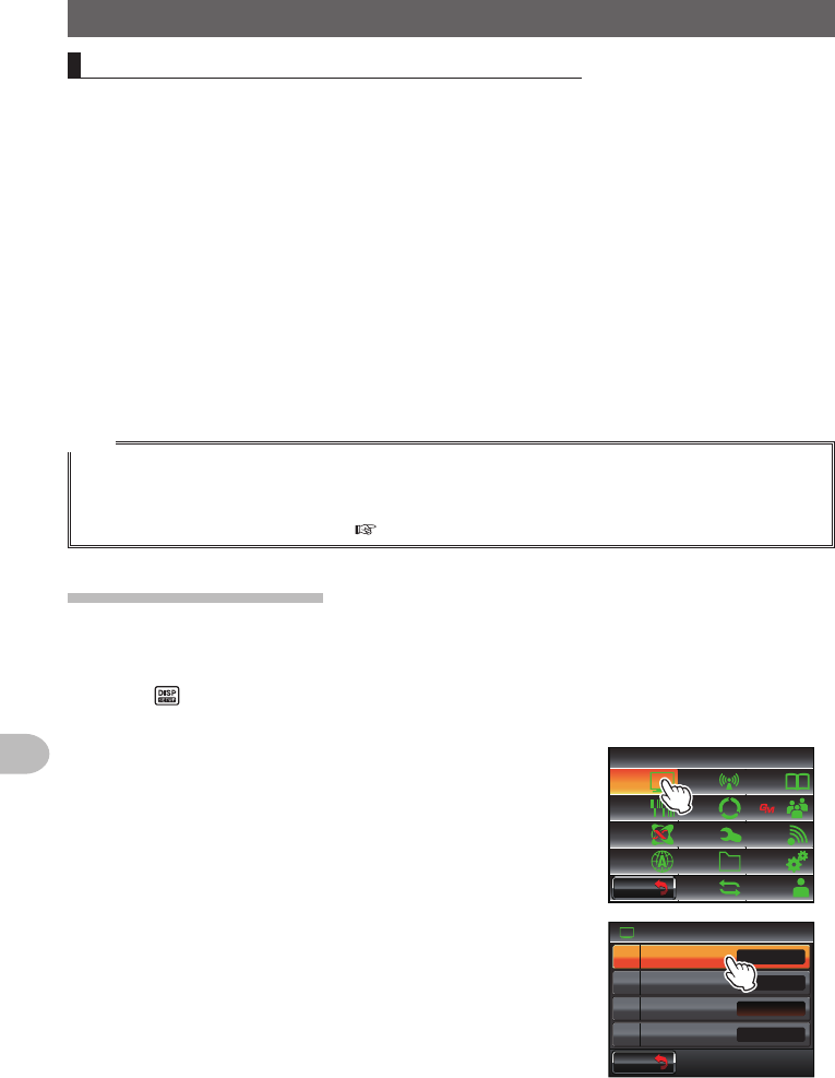
Measuringthealtitude
The changes in the altitude depending on the altitude of the current position and
distance travelled can also be displayed in a graph.
1 Press for one second or longer
The set-up menu will be displayed.
2 Touch [DISPLAY]
The menu list will be displayed.
$#%-
$#%-
6:4:
5'672/'07
4'5'6
%.10'
%10(+)9Ჰ4'5
5%#0
&+52.#;
5+) 0#.+0)
#245 126+10
5&%#4&
/'/14;
#
%#..5+) 0
3 Touch [1DISPLAYSELECT]
A list of the various screen setting selections will be
displayed.
Ż
6#4)'6.1%#6+10
&+52.#;
&+52.#;5'.'%6
#0)'41
$#%-)4170&%1.14
07/'4+%
9+&'$#0&5%12'
Ჹ
Ჺ
$#%-
$#%-
Application for FCC / IC
FCC ID: K6620345X40 / IC: 511B-20345X40
91
Using the GPS Function
PositioningUsingGPS
4 Touch [ALTITUDE] to select “ON”
Each time this symbol is touched, the setting will
switch between “OFF” and “ON”.
&+52.#;
)25+0(1
#.6+67&'((1
01
((1
6+/'4%.1%-
&+52.#;5'.'%6Ჹ
$#%-
$#%-
5 Press for one second or longer
The display will return to the previous screen.
6 Press twice briefly
The altitude graph will be displayed on the screen.
ᲺᲽ᳀O
#.6+67&'
5%#.
'%
.'#4
Ჸ
ᲹᲽᲸᲸ18(
18( Ჸ
ᲸᲸ
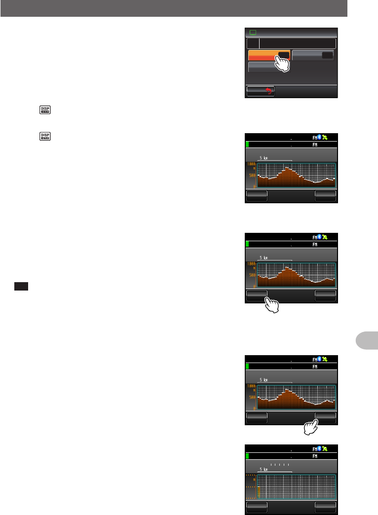
●Changingthealtitude scale
1 Touch [SCALE]
Each time this symbol is touched, the scale value will
change in the following order.
“5 m” → “20 m” → “40 m” → “80 m”
Tip The maximum altitude scale will be automatically set
based on the present altitude values.
ᲺᲽ᳀O
#.6+67&'
5%#.
'%
.'#4
Ჸ
ᲹᲽᲸᲸ18(
18( Ჸ
ᲸᲸ
●Erasingthepreviousaltitudechanges
1 Touch [CLEAR]
The graph on the left side will disappear and the
current altitude display will shift to the left end.
ᲺᲽ᳀O
#.6+67&'
5%#.
'%
.'#4
Ჸ
ᲹᲽᲸᲸ18(
18( Ჸ
ᲸᲸ
O
#.6+67&'
5%#.
'%
.'#4
Ჸ
ᲹᲽᲸᲸ18(
18( Ჸ
ᲸᲸ
Application for FCC / IC
FCC ID: K6620345X40 / IC: 511B-20345X40

92
Using the GPS Function
PositioningUsingGPS
Othersettings
●Changingthegeodeticreferencesystem
Select using [CONFIG] → [16GPSDATUM] in the set-up menu.
Select the geodetic reference system which is the positioning standard.
“WGS-84”: Using the global geodetic reference system for positioning. This is being
used as a standard all around the world.
“TOKYO MEAN”: Using the Japanese geodetic reference system for positioning.
When positioning in Japan (Tokyo), the error can be lowered.
Tips
• When the geodetic reference system is changed, the position information will deviate by about
400 m.
• Set to “WGS-84” normally.
●Changingthetimezone
Select using [CONFIG] → [3TIMEZONE] in the set-up menu.
The time difference with the UTC (Coordinated Universal Time) can be changed in steps
of 30 minutes.
Application for FCC / IC
FCC ID: K6620345X40 / IC: 511B-20345X40
93
Using the GPS Function
UsingtheSmartNavigationFunction
Two navigation methods may be used in the smart navigation function.
(1) Real-time navigation function
In the C4FM digital V/D mode, the position and direction of the received partner
station can be displayed in real time during the communication because the position
information obtained from the GPS is transmitted at the same time as the voice signal.
(2) Backtrack function
By registering the departure or other points in advance, the distance and direction
from the current position to the registered location can be displayed in real time.
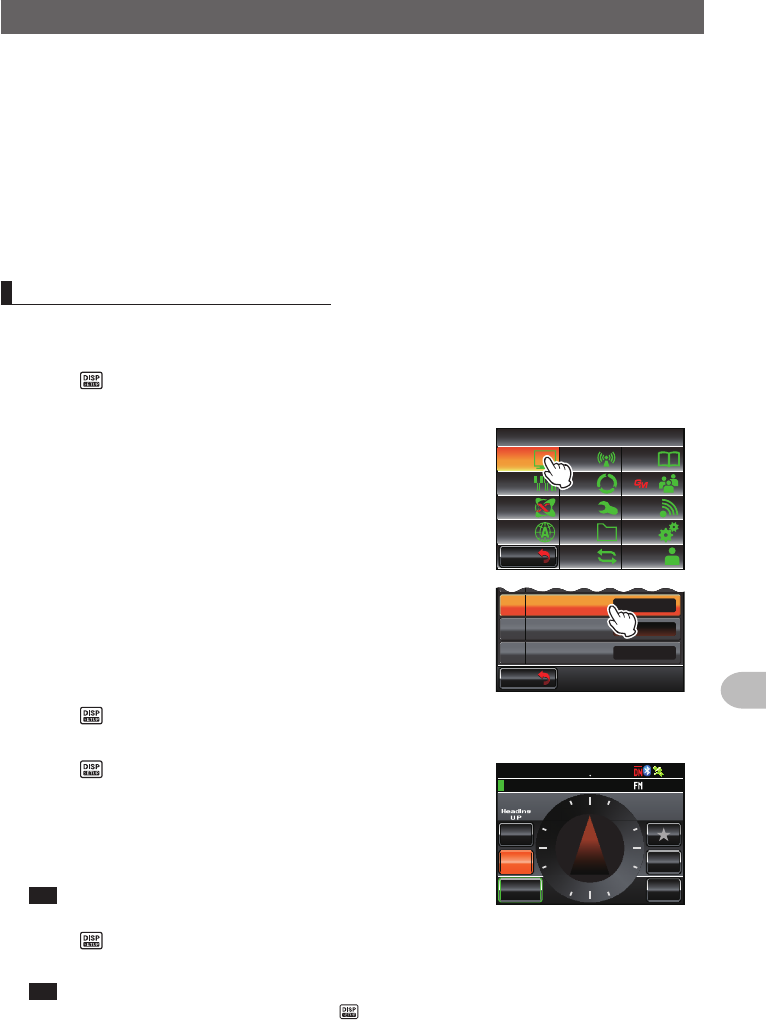
DisplayingtheCompassscreen
When using the navigation function, use the “Compass Screen” to display the direction
of your station and the partner station on a compass.
1 Press for one second or longer
The set-up menu will be displayed.
2 Touch [DISPLAY]
The menu list will be displayed.
$#%-
$#%-
6:4:
5'672/'07
4'5'6
%.10'
%10(+)9Ჰ4'5
5%#0
&+52.#;
5+) 0#.+0)
#245 126+10
5&%#4&
/'/14;
#
%#..5+) 0
3 Touch [2TARGETLOCATION] to select
“COMPASS”
Each time this symbol is touched, the setting will
switch between “COMPASS” and “NUMERIC”.
Ż
6#4)'6.1%#6+10
&+52.#;5'.'%6
#0)'41
$#%-)4170&%1.14
9+&'$#0&5%12'
Ჹ
Ჺ
$#%-
$#%-
07/'4+%
4 Press for one second or longer
The display will return to the previous screen.
5 Press briefly
The screen with the compass panel in the center will
be displayed.
The direction from your station to the partner station
will also be displayed using a compass needle.
Tip The compass needle will not be displayed when there is
no position information.
%1/2#55 &+56#0%'
/;
;4
.Ჺ
.Ჹ
/'/14;
ᲸᲽ
ᲹᲺ ᲹᲽᲾᲺ
Ჽ6-;11
Ჺ
ᲸᲸ
MO
␃␃␃␃
0
9
'
5
6 Press briefly
The display will return to the normal frequency display screen from the Compass screen.
Tip When the Altitude display screen and Timer/Clock screen are both “ON”, the screen will
change in the following order each time is pressed.
Normal frequency display → Compass/Lat&Lon display screen → Altitude display screen →
Timer/Clock screen → GPS screen
Application for FCC / IC
FCC ID: K6620345X40 / IC: 511B-20345X40
94
Using the GPS Function
UsingtheSmartNavigationFunction
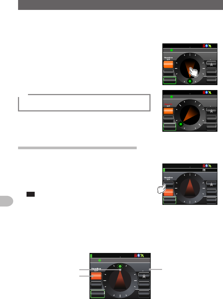
●Changingthedirectionofthecompasspanel
The compass panel can be selected from “Heading UP” where the direction of your
travel is always displayed at the top, or “North UP” where north is always displayed at
the top.
1 Touch the compass needle
The compass panel will switch between “Heading
UP” and “North UP” each time the compass needle is
touched.
The direction of the current compass panel will be
Indicated near the top left of the screen.
Tip
Although the scale on the compass panel has 16 directions, the
compass needle can point in 32 directions.
%1/2#55 &+56#0%'
/;
;4
.Ჺ
.Ჹ
/'/14;
ᲸᲽ
ᲹᲺ ᲹᲽᲾᲺ
Ჸ᳁᳁᳁
MO
0
9
'
5
Ჹ
,#<4.Ჺ
Ჹ
%1/2#55 &+56#0%'
/;
;4
.Ჺ
.Ჹ
/'/14;
ᲸᲽ
ᲹᲺ ᲹᲽᲾᲺ
Ჸ᳁᳁᳁
MO
0
9'
5
Ჹ
,#<4.Ჺ
Ჹ
Usingthereal-timenavigationfunction
1 Switch to the Compass screen
2 Touch [YR]
During transmission in the V/D mode, the distance
and direction of the received partner station is
displayed.
Tip When a partner station is selected using the GM function
and displayed on the compass screen, the “●” on the left
hand side of the partner station call sign will blink.
When “●” is blinking, the compass display will not
be updated even when signals containing position
information from stations other than that displayed are
received.
%1/2#55
ᲸᲹᲽᲾᲺ
&+56#0%'
/;
;4
.Ჺ
.Ჹ
/'/14;
ᲽᲹᲺ
MO
␃␃␃␃
Ჽ6-;11
Ჺ
ᲸᲸ
0
9
'
5
When [YR] is touched, “●” will light up and the compass display will be updated when signals
containing position information from stations other than that displayed are received.
%1/2#55
ᲸᲹᲽᲾᲺ
&+56#0%'
/;
;4
.Ჺ
.Ჹ
/'/14;
ᲽᲹᲺ
Ჸ᳁᳁᳁
MO
0
9
'
5
Ჹ
,#<4.Ჺ
Ჹ
Direction of partner statio
n
Partner station information
in display
Distance to partner station
Application for FCC / IC
FCC ID: K6620345X40 / IC: 511B-20345X40