Yaesu Musen 20345X40 AMATEUR RADIO WITH SCANNING RECEIVER User Manual OM
Yaesu Musen Co., Ltd. AMATEUR RADIO WITH SCANNING RECEIVER OM
Contents
- 1. User Manual
- 2. User Manual 1
- 3. User Manual 2
- 4. User Manual 3
- 5. User Manual 4
- 6. User Manual 5
- 7. User Manual 6
- 8. User Manual 7
- 9. User Manual 8
- 10. User Manual 9
- 11. User Manual 10
- 12. User Manual 11
- 13. User Manual 12
- 14. User Manual 13
- 15. User Manual 14
- 16. User Manual 15
- 17. User Manual 16
- 18. User Manual 17
- 19. User Manual 18
- 20. User Manual 19
- 21. User Manual 20
- 22. User Manual 21
User Manual 15
151
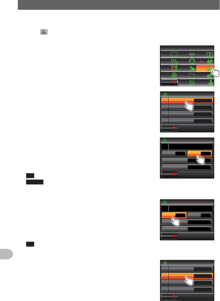
Functions to be Used when Necessary
CopyingtheRadioDatatoanotherTransceiver
The memory channels and settings in the set-up menu can be copied to another FTM-
400XDR/DE. This is convenient when matching the settings of fellow stations that you
communicate with frequently.
Usingthemicro-SDcard
The data files saved in the FTM-400XDR/DE can be selected and copied to a micro-SD
card.
Copyingdatatoamicro-SDcard
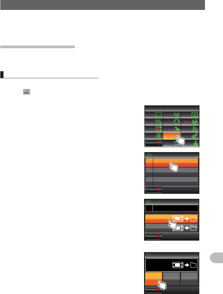
1 Insert the micro-SD card into the main body card slot
2 Press for one second or longer
The set-up menu will be displayed.
3 Touch [SDCARD]
The menu list will be displayed.
$#%-
$#%-
6:4:
5'672/'07
4'5'6
%.10'
%10(+)9Ჰ4'5
5%#0
&+52.#;
5+) 0#.+0)
#245 126+10
5&%#4&
/'/14;
#
%#..5+) 0
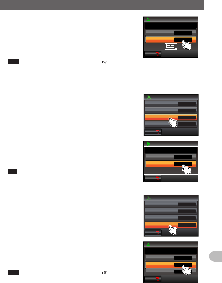
4 Select and touch [1BACKUP]
The screen for selecting the copy direction will be
displayed.
)4172+&
$#%-72
(14/#6
Ჹ
Ჺ
5&%#4&
$#%-
$#%-
5 Touch [WritetoSD]
The screen for selecting the data files to be copied will
be displayed.
“ALL”: Copies all data.
“MEMORY”: Copies only the memory channels and
position information for backtrack use.
“SETUP”: Copies only the settings in the set-up menu.
$#%-
$#%-
$#%-72
5&%#4&
&5QVGVᲲT9
5&QOTHFCG4
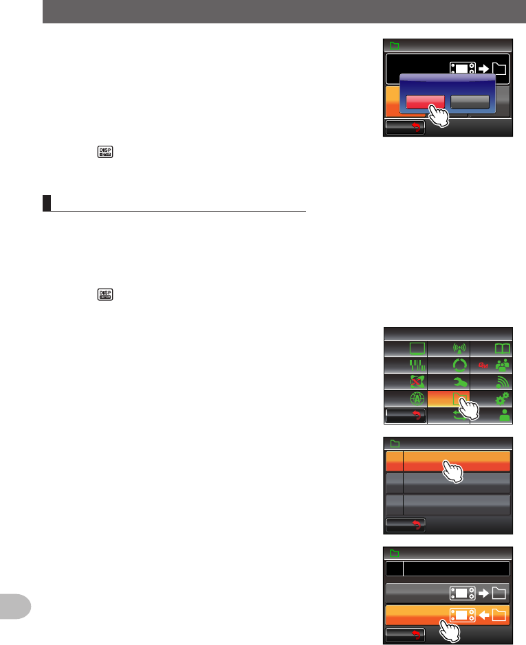
6 Select and touch the file to be copied
The confirmation screen will be displayed.
$#%-
$#%-
5&%#4&
&5QVGVᲲT9
#.. /'/14;5'672
$#%-72
Application for FCC / IC
FCC ID: K6620345X40 / IC: 511B-20345X40
152
Functions to be Used when Necessary
CopyingtheRadioDatatoanotherTransceiver
7 Touch [OK?]
The data selected in Step 6 will be copied to the
micro-SD card.
“Completed” will be displayed when the copying is
completed.
$#%-
$#%-
5&%#4&
&5QVGVᲲT9
#.. /'/14;5'672
$#%-72
%CPEGᲴ1-!
#..
8 Press for one second or longer
The display will return to the previous screen.
Copyingdatafromthemicro-SDcard
1 Insert the micro-SD card into the FTM-400XDR/DE where the data is stored and
copy the data to the card
2 Remove the micro-SD card and insert it into the FTM-400XDR/DE that the data is
going to be copied to
3 Press for one second or longer
The set-up menu will be displayed.
4 Touch [SDCARD]
The menu list will be displayed.
$#%-
$#%-
6:4:
5'672/'07
4'5'6
%.10'
%10(+)9Ჰ4'5
5%#0
&+52.#;
5+) 0#.+0)
#245 126+10
5&%#4&
/'/14;
#
%#..5+) 0
5 Select and touch [1BACKUP]
The screen for selecting the copy direction will be
displayed.
)4172+&
$#%-72
(14/#6
Ჹ
Ჺ
5&%#4&
$#%-
$#%-
6 Touch [ReadfromSD]
The screen for selecting the data files to be copied
will be displayed.
“ALL”: Copies all data.
“MEMORY”: Copies only the memory channels and
position information for backtrack use.
“SETUP”: Copies only the settings in the set-up
menu.
$#%-
$#%-
$#%-72
5&%#4&
&5QVGVᲲT9
5&QOTHFCG4
Application for FCC / IC
FCC ID: K6620345X40 / IC: 511B-20345X40
153
Functions to be Used when Necessary
CopyingtheRadioDatatoanotherTransceiver
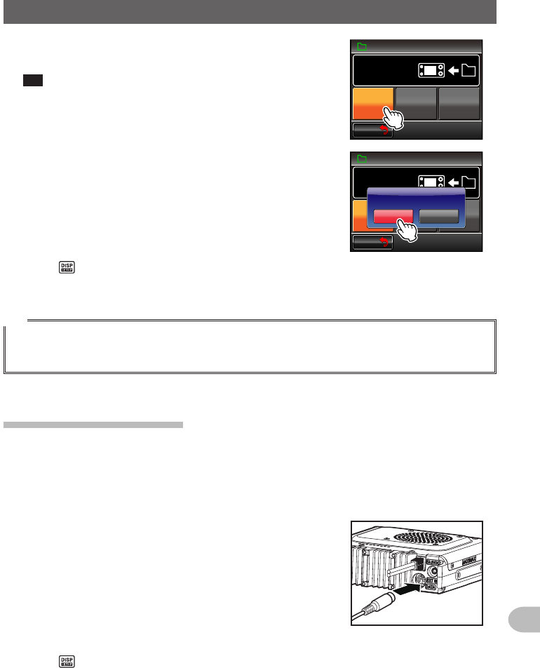
7 Select and touch the data to be copied
The confirmation screen will be displayed.
Tip Data that has not been saved in the micro-SD card
cannot be touched.
$#%-
$#%-
5&%#4&
#.. /'/14;5'672
$#%-72
5&QOTHFCG4
8 Touch [OK?]
The data selected in Step 7 will be copied to the
micro-SD card.
“Completed” will be displayed when the copying is
completed.
$#%-
$#%-
5&%#4&
#.. /'/14;5'672
$#%-72
5&QOTHFCG4
%CPEGᲴ1-!
#..
9 Press for one second or longer
The display will return to the previous screen.
Tip
The group and member information saved in the memory using the GM function can be copied using
the micro-SD card. Refer to the separate Operating Manual GM Edition for details (download the
manual from the YAESU website).
Usingtheclone function
Using the clone function, all the data saved in the radio can be copied directly to another
FTM-400XDR/DE.
Example:WhenusingtheclonefunctionintwoFTM-400XDR/DEs
1 Turn both FTM-400XDR/DEs OFF
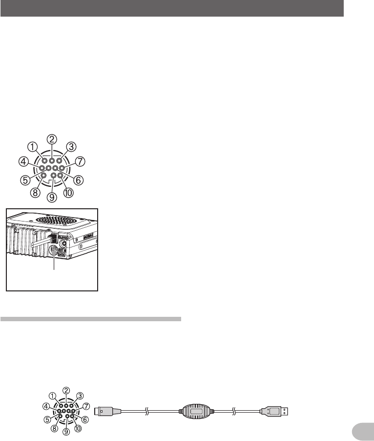
2 Plug in the optional clone cable “CT-166” into the
respective [DATA] jacks at the back of the main
bodies
3 Turn both FTM-400XDR/DEs ON
4 Press for one second or longer
The set-up menu will be displayed.
Application for FCC / IC
FCC ID: K6620345X40 / IC: 511B-20345X40
154
Functions to be Used when Necessary
CopyingtheRadioDatatoanotherTransceiver
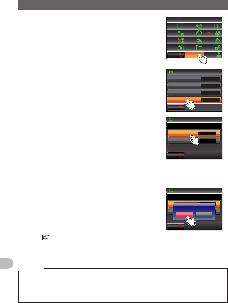
5 Touch [RESET/CLONE]
The menu list will be displayed.
$#%-
$#%-
6:4:
5'672/'07
4'5'6
%.10'
%10(+)9Ჰ4'5
5%#0
&+52.#;
5+) 0#.+0)
#245 126+10
5&%#4&
/'/14;
#
%#..5+) 0
6 Select and touch [7CLONE]
The screen for selecting the copy direction will be
displayed.
$#%-
$#%-
4'5'6%.10'
/'/%*4'5'6
/'/%*5146
#2454'5'6
%.10'
Ż
Ż
Ż
Ż
7 Select and touch [Thisradio→other] in the FTM-
400XDR/DE where the data is going to be copied
from
The confirmation screen will be displayed.
$#%-
$#%-
%.10'
4'5'6%.10'
QVJGTᲘ6J ᲲUTCF ᲲQ
Ż
Ż
6J ᲲUTCF ᲲQᲘQVJGT
8 Select and touch [Other→Thisradio] in the FTM-400XDR/DE where the data is
going to be copied to
The confirmation screen will be displayed.
9 Touch [OK?] for each one
The data will be copied.
“Completed” will be displayed when the copying is
completed.
$#%-
$#%-
%.10'
4'5'6%.10'
QVJGTᲘ6J ᲲUTCF ᲲQ
Ż
Ż
6J ᲲUTCF ᲲQᲘQVJGT
%CPEGᲴ1-!
6J ᲲUTCF ᲲQᲘQVJGT
%QPH ᲲTOᲲPI
10 Press for one second or longer
The display will return to the previous screen.
11 Switch OFF both of the FTM-400XDR/DEs and disconnect the clone cable
Cautions
zWhen “ERROR” is displayed during the copy (clone) operation, check the connection of the clone
cable and start the clone operation all again.
zWhen the operation is terminated before completion due to loss of power during the copy (clone)
operation, the FTM-400XDR/DE where the data is being copied to will automatically be reset.
Check if there is any abnormality in the power supply and start the cloning operation over again
Application for FCC / IC
FCC ID: K6620345X40 / IC: 511B-20345X40
155
Functions to be Used when Necessary
UsingtheRadiowithanExternalDeviceConnected
The provided PC connection cable “SCU-20” and other optional cables can be used to
connect the radio to a personal computer as a COM port for the following operations.
• Transmitting your own station position information to the personal computer for
incorporation into the map software
• Updating the firmware of the radio
• Packet communication
Use the [DATA] jack at the back of the main body to connect with the personal computer.
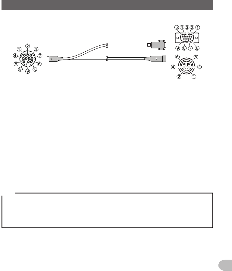
The pin assignment of the [DATA] jack is as follows.
[DATA]
jack
➀ PKD (packet data input) (300 mVp-p)
➁ GND
➂ PSK (PTT)
➃ RX 9600 (9600 bps packet data output)
➄ RX 1200 (1200 bps packet data output) (300 mVp-p)
➅ PK SQL (squelch control)
➆ TXD (serial data output [transceiver → PC])
➇ RXD (serial data input [transceiver ← PC])
➈ CTS (data communication control)
➉ RTS (data communication control)
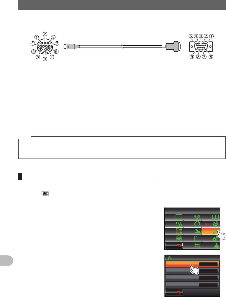
Connectingtoapersonalcomputer
●Preparations
• Personal computer
• PC connection cable “SCU-20” (accessories)… when connecting to the USB terminal
of a personal computer
To the transceiver
To the personal computer
(USB terminal)
➀ PKD (packet data input)
➁ GND
➂ PSK (PTT)
➃ RX 9600 (9600 bps packet data output)
➄ RX 1200 (1200 bps packet data output)
➅ PK SQL (squelch control)
➆ TXD (serial data output [transceiver → PC])
➇ RXD (serial data input [transceiver ← PC])
➈ CTS (data communication control)
➉ RTS (data communication control)
Application for FCC / IC
FCC ID: K6620345X40 / IC: 511B-20345X40
156
Functions to be Used when Necessary
UsingtheRadiowithanExternalDeviceConnected
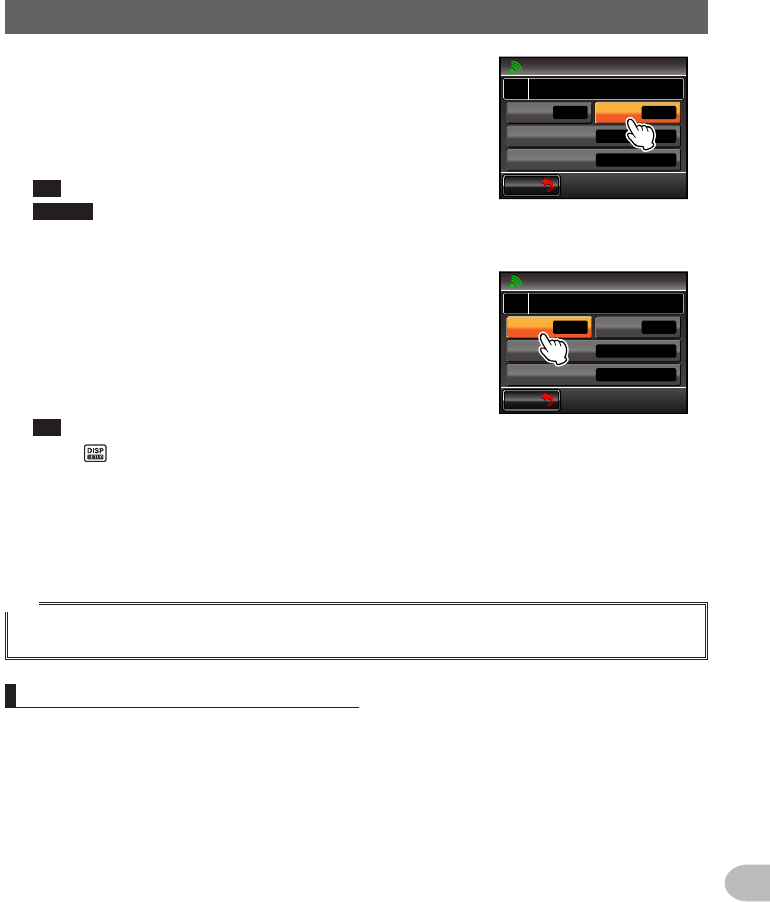
• Data cable “CT-165” (optional)… when connecting to the RS-232C terminal of a
personal computer
To the transceiver To the personal computer
➀ -
➁ GND
➂ -
➃ -
➄ -
➅ -
➆ TXD (serial data output [transceiver → PC])
➇ RXD (serial data input [transceiver ← PC])
➈ CTS (data communication control)
➉ RTS (data communication control)
➀ -
➁ TXD (serial data output [transceiver → PC])
➂ RXD (serial data input [transceiver ← PC])
➃ -
➄ GND
➅ -
➆ CTS (data communication control)
➇ RTS (data communication control)
➈ -
Tips
• Make sure to switch off the power to the radio first before connecting.
• When using the PC connection cable “SCU-20”, a dedicated driver needs to be installed in the
personal computer. Download and use the driver and installation manual from the YAESU website.
Sendingposition information to the computer
1 Turn the radio ON
2 Press for one second or longer
The set-up menu will be displayed.
3 Touch [DATA]
The menu list will be displayed.
$#%-
$#%-
6:4:
5'672/'07
4'5'6
%.10'
%10(+)9Ჰ4'5
5%#0
&+52.#;
5+) 0#.+0)
#245 126+10
5&%#4&
/'/14;
#
%#..5+) 0
4 Select and touch [1COMPORTSETTING]
The screen for the detailed settings will be displayed.
Ż
Ż
Ż
#$#0&5'.'%6
%1/21465'66+0)
#52''&
Ჹ
Ჺ
Ż
#537'.%*
#
$#%-
$#%-
Application for FCC / IC
FCC ID: K6620345X40 / IC: 511B-20345X40
157
Functions to be Used when Necessary
UsingtheRadiowithanExternalDeviceConnected
5 Touch [OUTPUT] to select “GPS OUT”
The setting changes as follows each time it is
touched.
“OFF(camera)” → “GPS OUT” → “PACKET” →
“WAYPOINT”
Tip Factory default value: OFF (camera)
Caution The snapshot function of the speaker microphone
with camera will be inactivated when this is set to
“OFF (camera)”.
$#%-
$#%-
%1/21465'66+0)
1((ECOGTC
52''&
92(+.6'4
176276
᳁ᲾᲸᲸDRU
#..
92(14/#6 0/'#
Ჹ
#
6 Touch [SPEED] to select the communication speed
of the COM port
The setting changes as follows each time it is
touched.
“4800 bps” → “9600 bps” → “19200 bps” → “38400
bps” → “57600 bps”
Tip Factory default value: 9600 bps
$#%-
$#%-
%1/21465'66+0)
)25176
52''&
92(+.6'4
176276
᳁ᲾᲸᲸDRU
#..
92(14/#6 0/'#
Ჹ
#
7 Press for one second or longer
The display will return to the previous screen.
The output of the position information data will start, and your own position
information will be transmitted to the personal computer at intervals of about a
second.
Tip
An operating software using NMEA-0183 standard GGA and RMC sentence is required to use the
position information.
Updatingthefirmwareoftheradio
The firmware of the radio can be updated by connecting to a personal computer when
Updated firmware is available.. Download and use the updated version of the firmware
and the update manual from the YAESU website.
Application for FCC / IC
FCC ID: K6620345X40 / IC: 511B-20345X40
158
Functions to be Used when Necessary
UsingtheRadiowithanExternalDeviceConnected
Usingtheradioasatransceiverforpacketcommunication
Packet communication via this radio is possible by connecting this radio to the TNC
(terminal node controller).
●Preparations
• TNC
• Personal computer
• Data cable* … Prepare a data cable to match the connecting device
* We supply the following optional products.
• Data cable “CT-167” (optional)
To the transceiver
To the TNC etc.
➀ PKD (packet data input)
➁ GND
➂ PSK (PTT)
➃ RX 9600 (9600 bps packet data output)
➄ RX 1200 (1200 bps packet data output)
➅ PK SQL (squelch control)
➆ TXD (serial data output [transceiver → PC])
➇ RXD (serial data input [transceiver ← PC])
➈ CTS (data communication control)
➉ RTS (data communication control)
➀ Brown PKD (packet data input)
➁ Black thick wire GND
➂ Red PSK (PTT)
➃ Orange RX 9600 (9600 bps packet data output)
➄ Yellow RX 1200 (1200 bps packet data output)
➅ Green PK SQL (squelch control)
➆ Blue TXD (serial data output) [transceiver → PC])
➇ Grey RXD (serial data input [transceiver ← PC])
➈ White CTS (data communication control)
➉ Black RTS (data communication control)
• Data cable “CT-164” (optional)
To the transceiver To the TNC etc.
➀ PKD (packet data input)
➁ GND
➂ PSK (PTT)
➃ RX 9600 (9600 bps packet data output)
➄ RX 1200 (1200 bps packet data output)
➅ PK SQL (squelch control)
➆ -
➇ -
➈ -
➉ -
➀ PKD (packet data input)
➁ GND
➂ PSK (PTT)
➃ RX 9600 (9600 bps packet data output)
➄ RX 1200 (1200 bps packet data output)
➅ PK SQL (squelch control)
Application for FCC / IC
FCC ID: K6620345X40 / IC: 511B-20345X40
159
Functions to be Used when Necessary
UsingtheRadiowithanExternalDeviceConnected
• Data cable “CT-163” (optional)
To the transceiver
To the personal computer etc.
To the TNC etc.
➀ PKD (packet data input)
➁ GND
➂ PSK (PTT)
➃ RX 9600 (9600 bps packet data output)
➄ RX 1200 (1200 bps packet data output)
➅ PK SQL (squelch control)
➆ TXD (serial data output [transceiver → PC])
➇ RXD (serial data input [transceiver ← PC])
➈ CTS (data communication control)
➉ RTS (data communication control)
Dsub9pin
➀ -
➁ TXD (serial data output [transceiver → PC])
➂ RXD (serial data input [transceiver ← PC])
➃ -
➄ GND
➅ -
➆ CTS (data communication control)
➇ RTS (data communication control)
➈ -
DIN6pin
➀ PKD (packet data input)
➁ GND
➂ PSK (PTT)
➃ RX 9600 (9600 bps packet data output)
➄ RX 1200 (1200 bps packet data output)
➅ PK SQL (squelch control)
Tips
• Make sure to turn the power to the radio OFF before connecting.
• Refer to the operating manual of the TNC used on how to connect the TNC to a personal computer.
• RF receive interference may occur because of noise occurring in the personal computer.
When signals cannot be received normally, keep the personal computer at a distance away from the
radio and use a photo-coupler and noise filter to connect.
Application for FCC / IC
FCC ID: K6620345X40 / IC: 511B-20345X40
160
Functions to be Used when Necessary
UsingtheRadiowithanExternalDeviceConnected
●Setthepacketcommunicationoperation
1 Turn the radio ON
2 Press for one second or longer
The set-up menu will be displayed.
3 Touch [DATA]
The menu list will be displayed.
$#%-
$#%-
6:4:
5'672/'07
4'5'6
%.10'
%10(+)9Ჰ4'5
5%#0
&+52.#;
5+) 0#.+0)
#245 126+10
5&%#4&
/'/14;
#
%#..5+) 0
4 Select and touch [1COMPORTSETTING]
The screen for the detailed settings will be displayed.
Ż
Ż
Ż
#$#0&5'.'%6
%1/21465'66+0)
#52''&
Ჹ
Ჺ
Ż
#537'.%*
#
$#%-
$#%-
5 Touch [OUTPUT] to select “PACKET”
The setting changes as follows each time it is
touched.
“OFF(camera)” → “GPS OUT” → “PACKET” →
“WAYPOINT”
Tip Factory default value: OFF (camera)
Caution The snapshot function of the speaker microphone
with camera will be inactivated when this is set to
“OFF (camera)”.
$#%-
$#%-
%1/21465'66+0)
1((ECOGTC
52''&
92(+.6'4
176276
᳁ᲾᲸᲸDRU
#..
92(14/#6 0/'#
Ჹ
#
6 Touch [SPEED] to select the communication speed
of the COM port
The setting changes as follows each time it is
touched.
“4800 bps” → “9600 bps” → “19200 bps” → “38400
bps” → “57600 bps”
Tip Factory default value: 9600 bps
7 Touch [BACK]
$#%-
$#%-
%1/21465'66+0)
)25176
52''&
92(+.6'4
176276
᳁ᲾᲸᲸDRU
#..
92(14/#6 0/'#
Ჹ
#
8 Select and touch [2DATABANDSELECT]
The screen for the detailed settings will be displayed.
Ż
Ż
Ż
#$#0&5'.'%6
%1/21465'66+0)
#52''&
Ჹ
Ჺ
Ż
#537'.%*
#
$#%-
$#%-
Application for FCC / IC
FCC ID: K6620345X40 / IC: 511B-20345X40
161
Functions to be Used when Necessary
UsingtheRadiowithanExternalDeviceConnected
9 Touch [DATA] to select the band to be used for the
packet communication
The setting changes as follows each time it is
touched.
“A-BAND FIX” → “B-BAND FIX” → “A=TX/B=RX” →
“A=RX/B=TX” → “MAIN BAND” → “SUB BAND”
Tips • Refer to “Data communication settings” ( P.193) for
details.
• Factory default value: B-BAND FIX
$#%-
$#%-
#$#0&5'.'%6
#
#245
#
#$#0&(+:
$$#0&(+:
10 Touch [BACK]
11 Select and touch [3DATASPEED]
The screen for the detailed settings will be displayed.
Ż
Ż
Ż
#$#0&5'.'%6
%1/21465'66+0)
#52''&
Ჹ
Ჺ
Ż
#537'.%*
#
$#%-
$#%-
12 Touch [DATA] to select the packet communication
speed
The setting will switch between “1200 bps” and “9600
bps” each time it is touched.
Tip Factory default value: 1200 bps
$#%-
$#%-
#52''&
#
#245
#
DRU
DRU
13 Touch [BACK]
14 Select and touch [4DATASQUELCH]
The screen for the detailed settings will be displayed.
Ż
Ż
Ż
#$#0&5'.'%6
%1/21465'66+0)
#52''&
Ჹ
Ჺ
Ż
#537'.%*
#
$#%-
$#%-
15 Touch [DATA] to select the squelch detection method
for the packet communication
The setting switches between “RX BAND” and “TX/
RX BAND” each time it is touched.
Tips • Refer to “Data communication settings” ( P.193) for
details.
• Factory default value: RX BAND
$#%-
$#%-
#537'.%*
#
#245
#
4:$#0&
4:$#0&
6: 10
Application for FCC / IC
FCC ID: K6620345X40 / IC: 511B-20345X40
162
Functions to be Used when Necessary
UsingtheRadiowithanExternalDeviceConnected
16 Press for one second or longer
The display will return to the previous screen.
Packet communication will be enabled.
17 Choose the band and frequency according to the settings in the set-up menu
18 Turn of the receive band
The output level to TNC from the radio will be set.
19 Adjust the TNC output level
The input level to the radio will be set.
Caution
When transmitting a large volume of data, the transmission time gets longer and the radio will get
heated up. When transmission continues for a long period of time, the overheating prevention circuit
will act to lower the transmit power output. When transmission is continued further, transmission will
be suspended automatically and the radio will go into the receive mode in order to prevent failure due
to overheating.
When the overheating prevention circuit is activated and the radio goes into the receive mode, either
switch turn OFF the power, or wait until the temperature drops in the reception mode.
Otherdevicesthatcanbeconnected
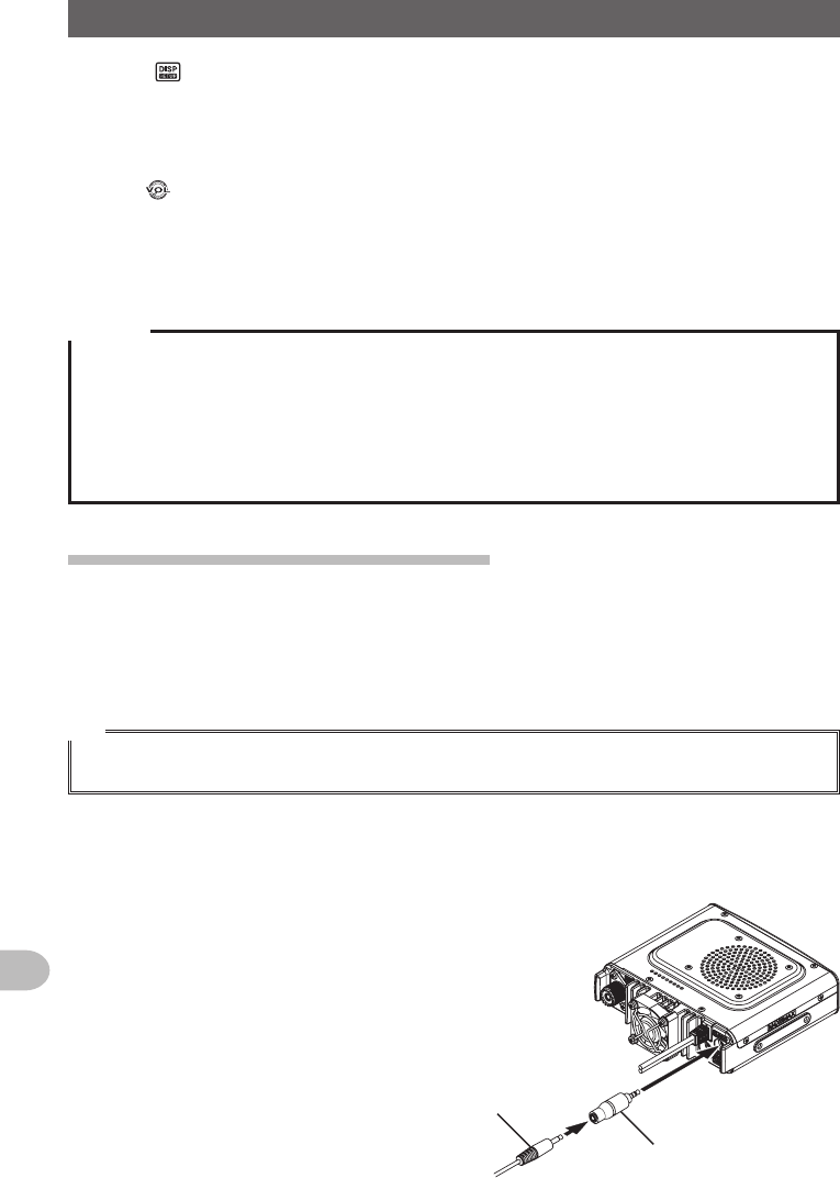
●Externalspeaker
An optional high output and high sound quality waterproof external speaker “MLS-
200-M10” can be connected.
Plug the external speaker into the [EXT SP] jack at the back of the main body.
Tip
When an external speaker is connected to the [EXT SP] jack, there will be no sound from the internal
speaker.
If you connect an External Speaker other than the MLS-200-M10 to the [EXT SP] Jack,
use a Stereo Speaker only (Do not connect a Monaural Speaker plug directly into the
[EXT SP] Jack.)
If you wish to connect a Monaural Speaker to
the [EXT SP] Jack, use the supplied "Stereo to
Monaural Plug" (see figure).
StereotoMonauralPlug
MonauralSpeakerPlug
Application for FCC / IC
FCC ID: K6620345X40 / IC: 511B-20345X40
163
Customize Menu Settings and User Preferences
Using the set-up menu, the various functions of the radio can be customized to match
your individual preferences and type of use. The functions are divided into menus such
as display, transmission and reception, memory, device configuration etc.. It is easy to
select the items that you would like to adjust from the respective lists and enter or select
the settings that are easy to use.
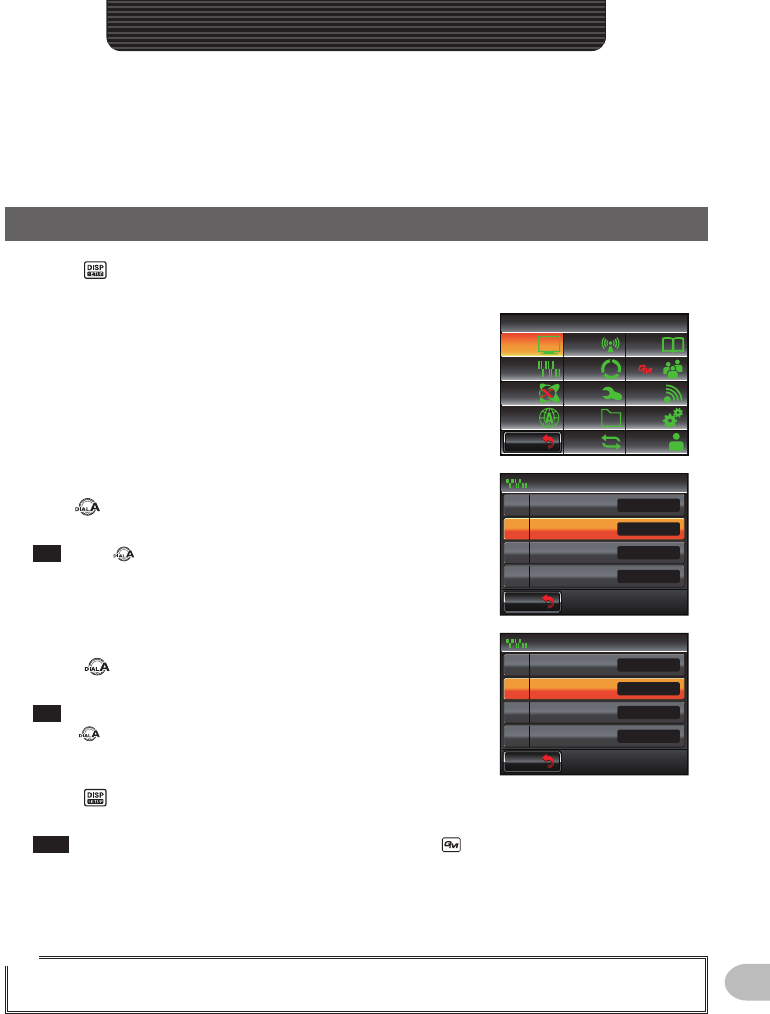
Set-upMenuBasicOperations
1 Press for one second or longer
The set-up menu will be displayed.
2 Touch the menu item
The menu list will be displayed.
$#%-
$#%-
6:4:
5'672/'07
4'5'6
%.10'
%10(+)9Ჰ4'5
5%#0
&+52.#;
5+) 0#.+0)
#245 126+10
5&%#4&
/'/14;
#
%#..5+) 0
3 Select the item to be set
Turn or touch the item.
The item will turn orange in color.
Tip Turn to select items that are not visible on the
screen.
$#%-
$#%-
24)4'8610'
2#)'4%1&'
53.':2#05+10
$'..4+0)'4
5+) 0#.+0)
1((
1((
*\
ᲸᲸᲹᲽ
Ჽ
Ჾ
Ჿ
᳀
Ż
4 Change the set values
Press briefly or touch the item.
The set value will change each time it is pressed or touched.
Tip When “>” is displayed in the set value field, pressing
or touching an item will display the screen with the
detailed settings.
$#%-
$#%-
24)4'8610'
2#)'4%1&'
53.':2#05+10
$'..4+0)'4
5+) 0#.+0)
1((
1((
*\
ᲸᲸᲹᲽ
Ჽ
Ჾ
Ჿ
᳀
Ż
5 Press for one second or longer, or press [PTT] on the microphone
The chosen value will be confirmed and the display will return to the previous screen.
Tips • The chosen value can also be confirmed by pressing briefly.
• When setting additional items in the same menu next, touch [BACK]. The set value will be
confirmed and the display will return to the menu list screen.
• When [BACK] is touched in any of the screens, the display will return to the previous screen.
Tip
When a set menu item is touched again, and the menu list is displayed, a screen in which a
previously set item is already selected (displayed in orange color) will be displayed.
CustomizeMenuSettingsandUserPreferences
Application for FCC / IC
FCC ID: K6620345X40 / IC: 511B-20345X40