Zultys Technologies ZIP4X5 Bluetooth FHSS transceiver in VOIP Phone User Manual ZIP 4x4 User s Manual 1 0 2 20 April 2003
Zultys Technologies Bluetooth FHSS transceiver in VOIP Phone ZIP 4x4 User s Manual 1 0 2 20 April 2003
Contents
- 1. Manual 1
- 2. Manual 2
- 3. Manual 3
- 4. Manual 4
Manual 4


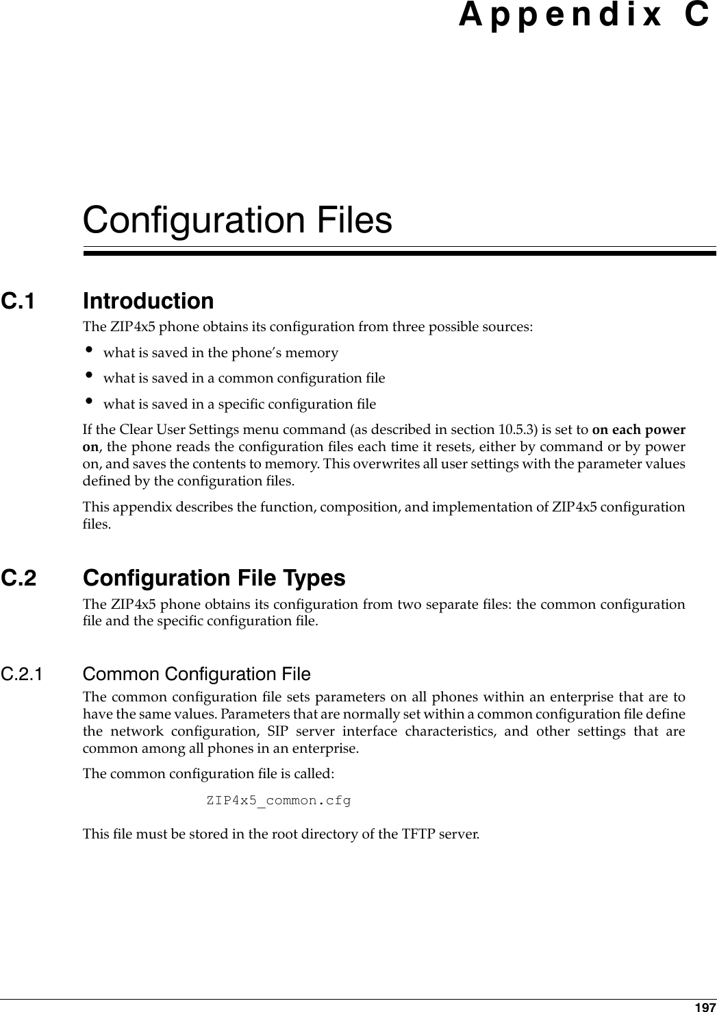
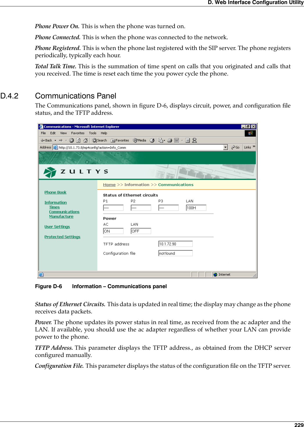
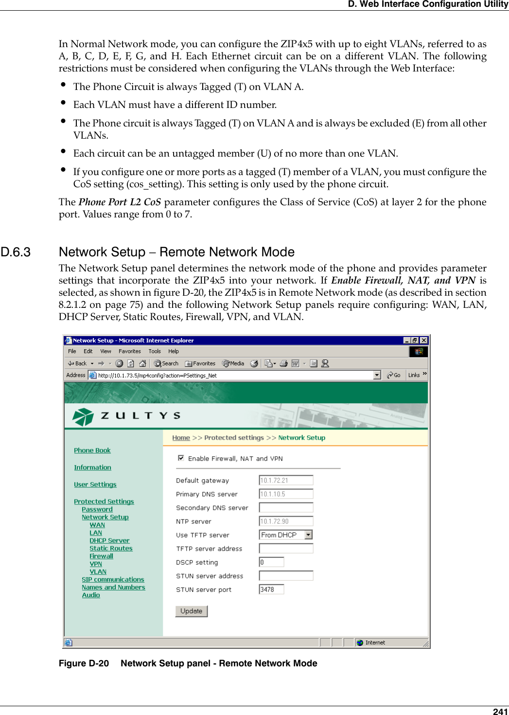
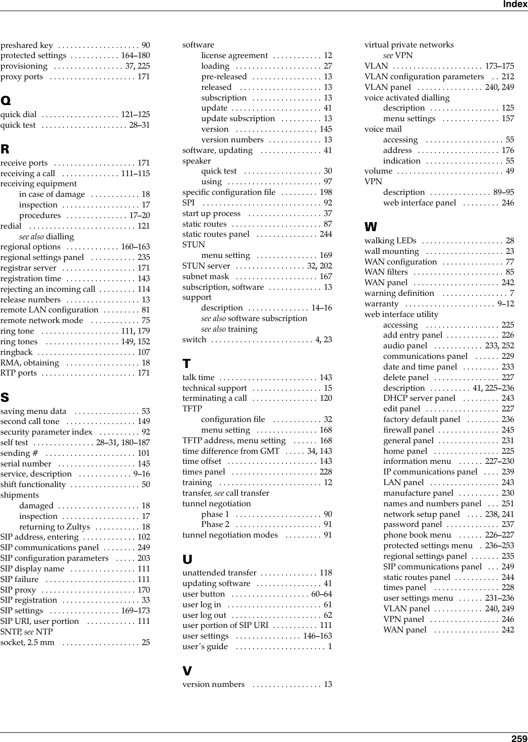
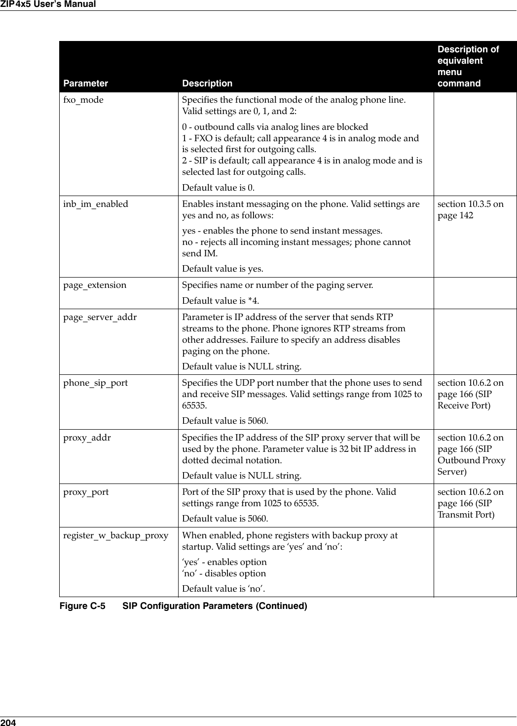
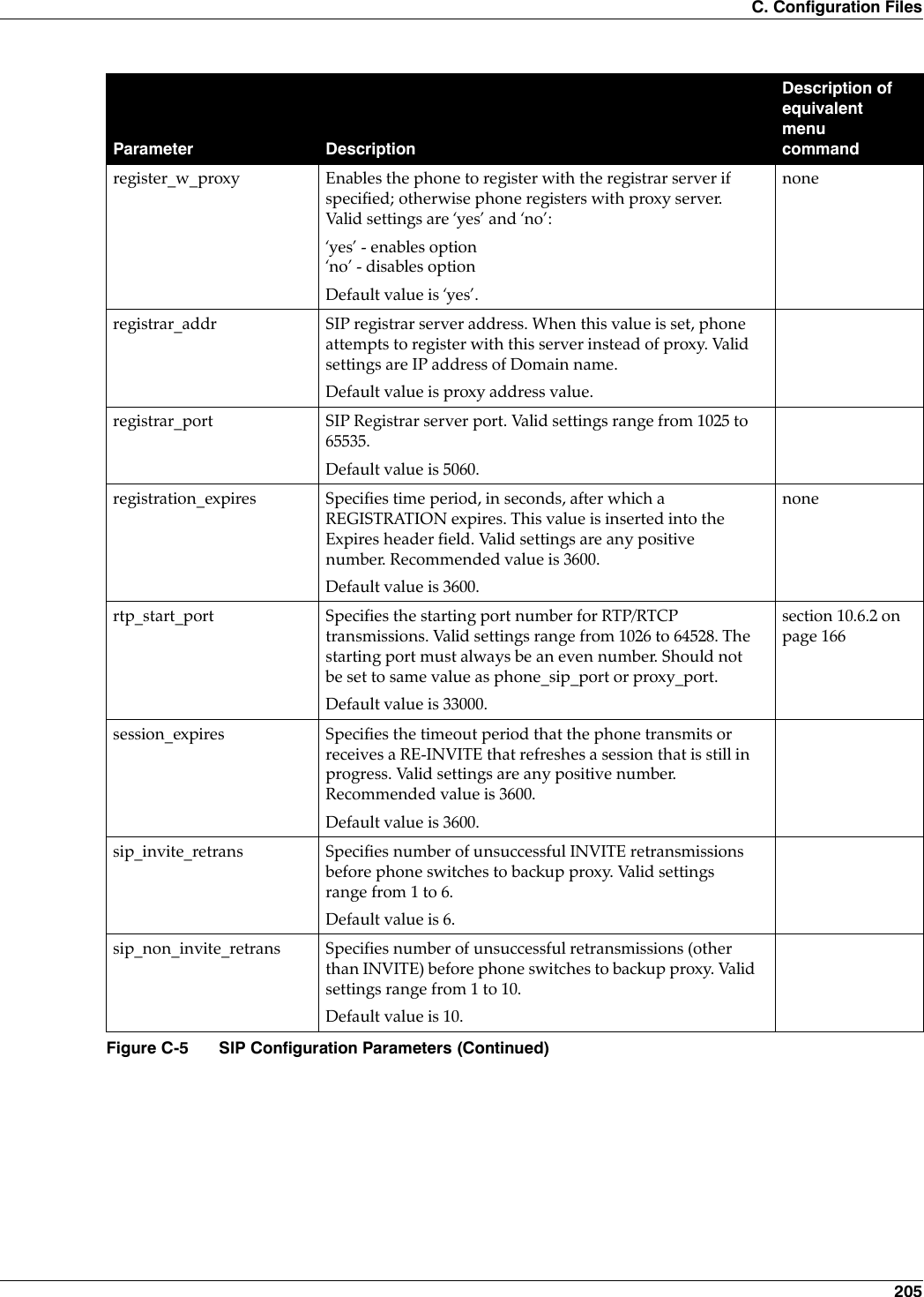
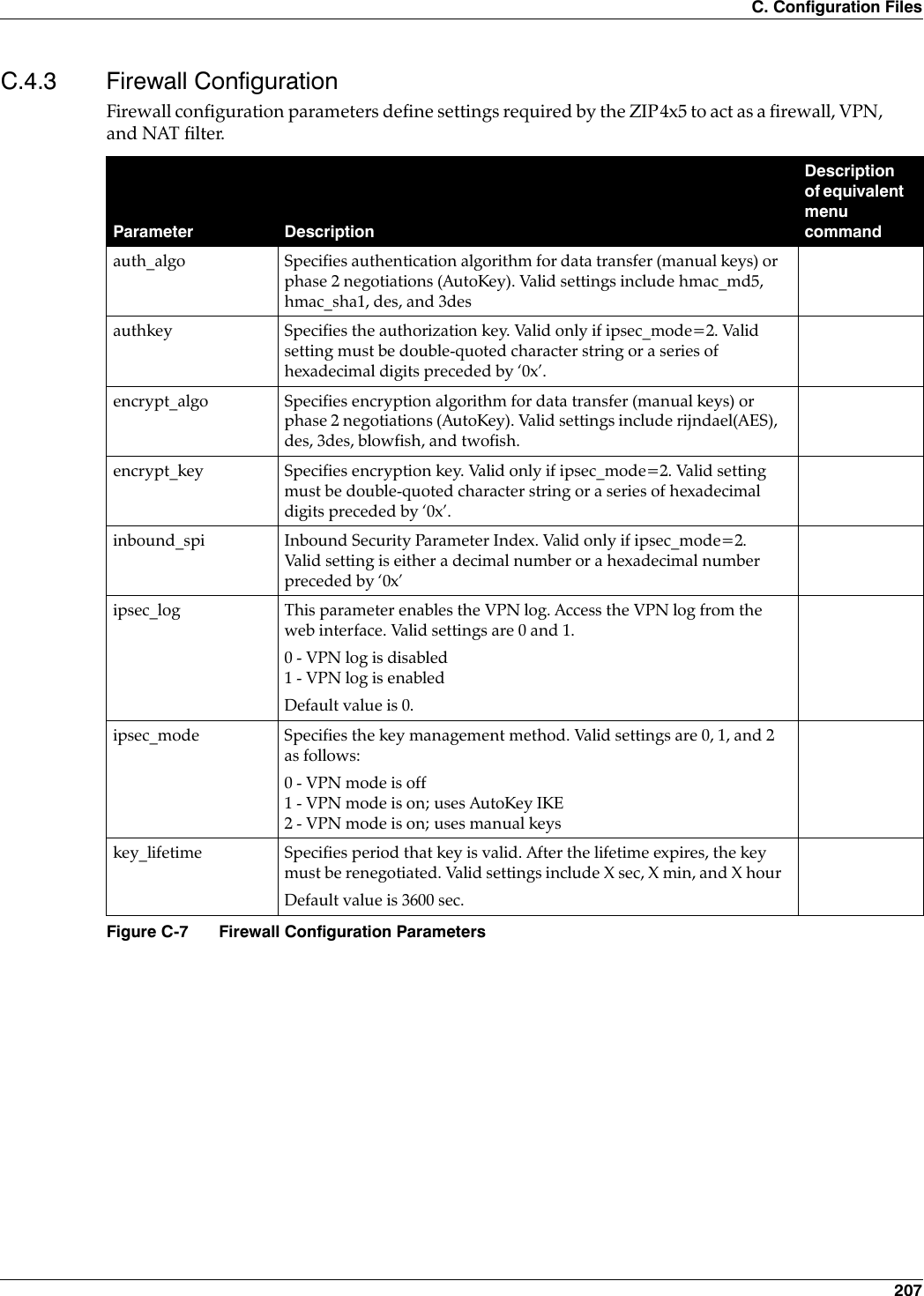
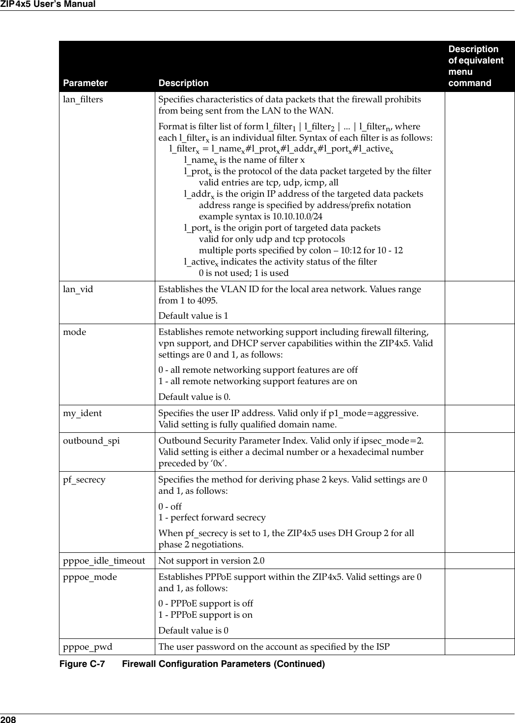
![198ZIP4x5 User’s ManualC.2.2 Specific Configuration FileThe specific configuration file sets parameters for an individual phone within an enterprise.Parameters normally set within a specific configuration file customize ZIP4x5 features for theperson using the phone, such as the greeting message, audio characteristics, and LCD options.The common configuration file identifies the location of the specific configuration files. A phoneextracts configuration information from the common file first, then from its specific file. Specificfile parameter settings take precedence over settings of the same parameters in the common file. The name of the specific configuration file is:<MAC address>.cfgFor example,0050C2180FD8.cfgis the specific configuration file for a ZIP4x5 phone that has the MAC address 00:50:C2:18:0F:D8.C.3 Configuration File FormatCommon and specific configuration files are similar in format and composition. Mostconfiguration parameters can be set in either file. Configuration files are stored in ASCII format. C.3.1 File SectionsEach file is separated into sections, with each section containing settings for a functionalparameter group. The order of the functional sections within each configuration file has no affectupon the configuration of the phone. The first line in each section contains the name of thefunctional group, denoted by square brackets. Figure C-1 displays the name of each functionheading and the proper format of the headings.[HW_CONFIG][VLAN_CONFIG][NET_CONFIG][SIP_CONFIG][AUDIO_INFO][GENERAL_INFO][BT][FW][DHCP_SRV]Figure C-1 Configuration File Section Headings](https://usermanual.wiki/Zultys-Technologies/ZIP4X5.Manual-4/User-Guide-458736-Page-10.png)
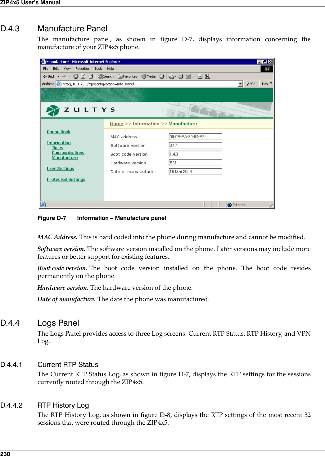
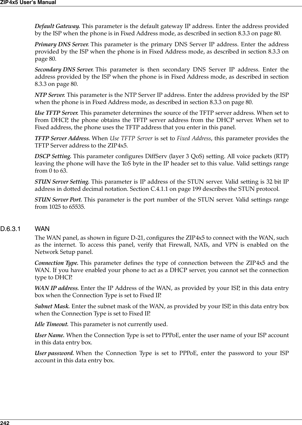
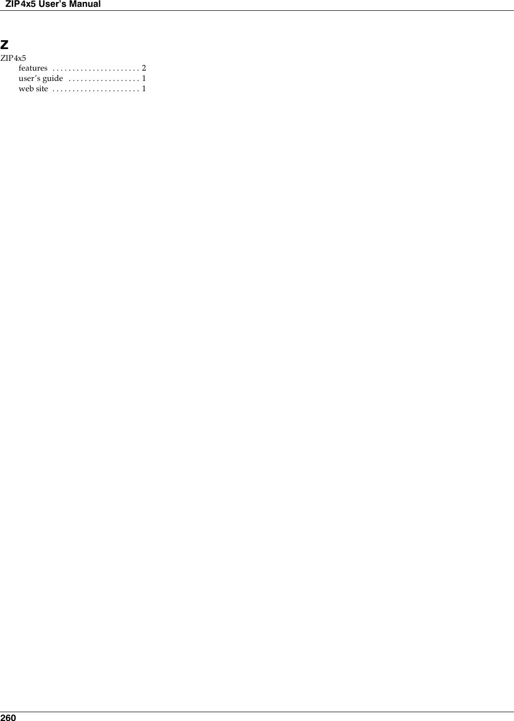
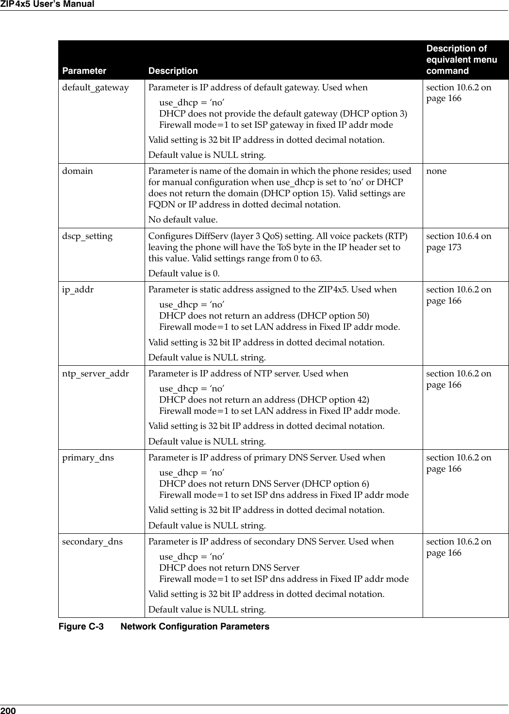
![C. Configuration Files 199C.3.2 Parameter EntriesAll available parameter settings are classified by function, as described in section C.4. Eachparameter within a configuration file must be contained within its defined functional section. Theorder of parameters within each function section does not effect the configuration of the phone.If a parameter is defined in the common file and the specific file, the specific file setting takesprecedence. Figure C-2 displays an example of parameter settings in a configuration file.The name of the parameter and the parameter value must be on the same line. The name of theparameter is not case sensitive; it can be entered in either upper or lower case. However,parameter values are case sensitive. Refer to the parameter tables in section C.4 for more details.Comment lines are denoted with a leading semi-colon (;) and have no effect on the configurationof the phone.C.4 Configuration ParametersThis section provides tables that list all of the configuration parameters in each functional group.Parameters in each table are listed in alphabetic order. Many parameters correspond to anequivalent menu command; the tables refer to the section describing the menu command for eachof these parameters.C.4.1 Network ConfigurationNetwork configuration parameters define settings required by the phone to communicate withthe network. Figure C-3 lists the network configuration parameters.C.4.1.1 Server Parameter SettingsIt is highly recommended that the configuration files explicitly define the settings for these servervariables.use_dhcp: When DHCP is enabled, the DHCP server should dynamically provide an IP addressand subnet mask for the phone, IP addresses for the DNS servers, default gateway, NTP server,and TFTP server. If dhcp is not enabled, or if the DHCP is unable to return addresses for any of these servers, youmust specify valid IP addresses for each server or the phone will not properly configure onstartup.[HW_CONFIG]lcd_contrast=8ring_volume=5speaker_volume=5headset_volume=5handset_volume=5[NET_CONFIG]use_dhcp=yestftp_cfg_dir=./ZIP4x5Figure C-2 Configuration File Example](https://usermanual.wiki/Zultys-Technologies/ZIP4X5.Manual-4/User-Guide-458736-Page-11.png)
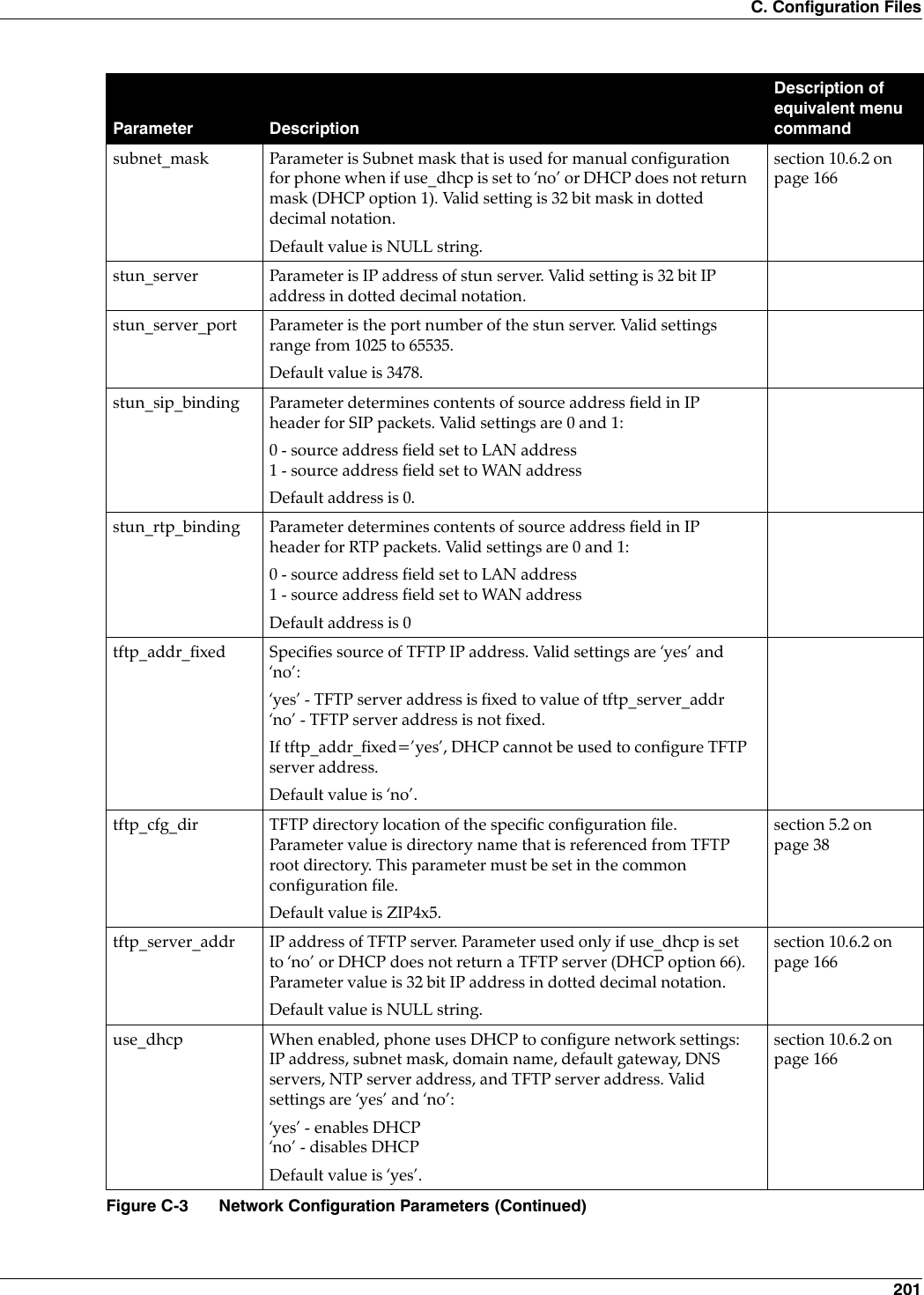
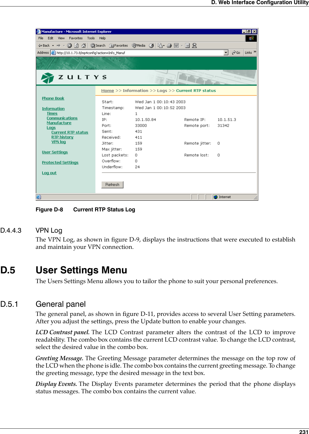
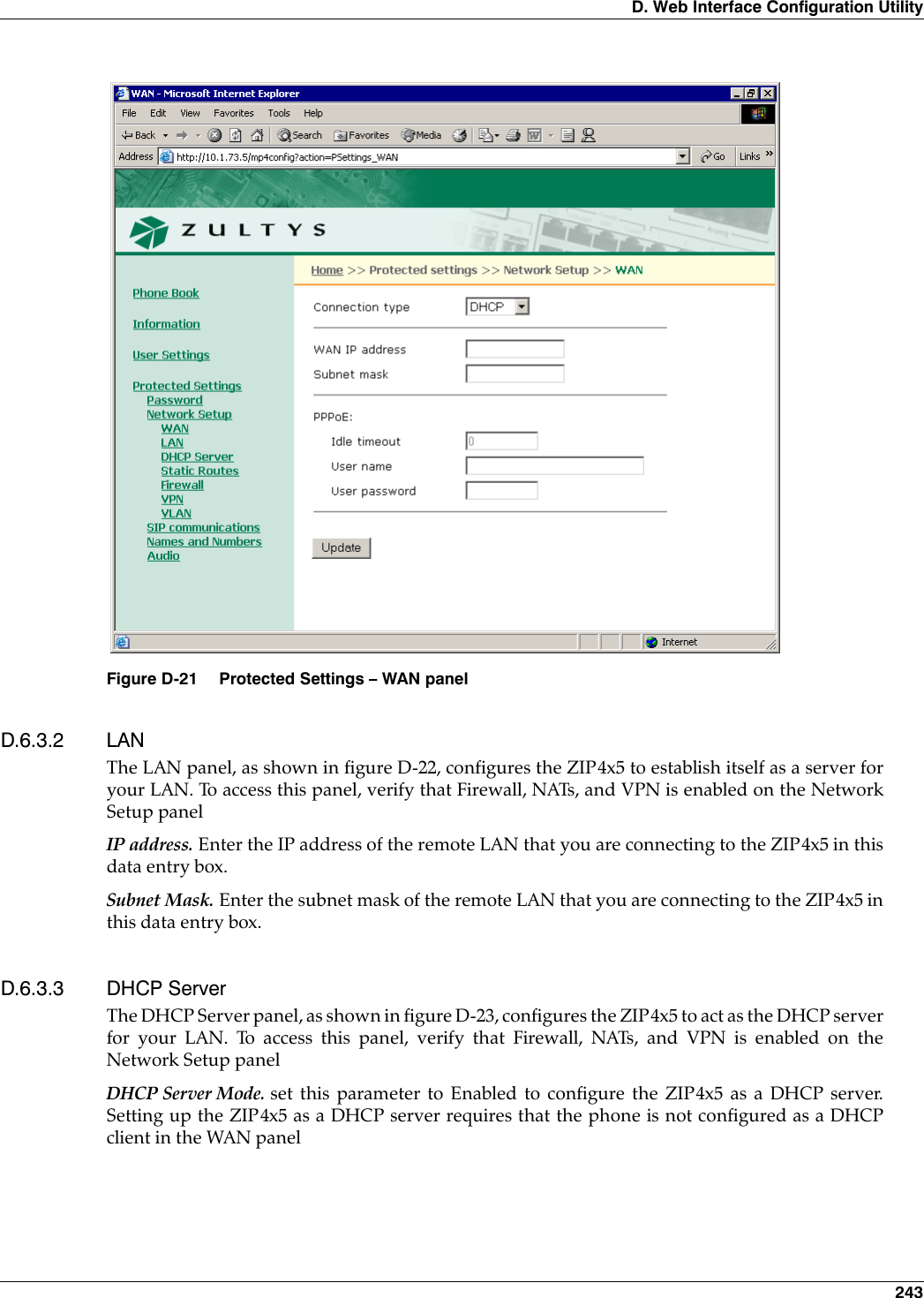
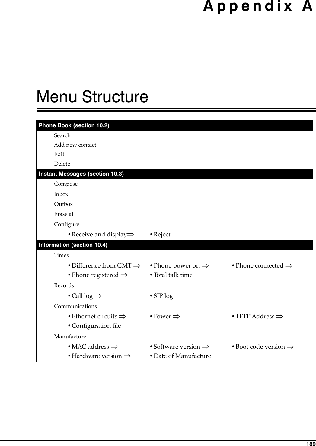
![202ZIP4x5 User’s Manualtftp_cfg_dir: This parameter points to the TFTP server directory that stores the specificconfiguration file for your phone. This parameter must be set in the common configuration file inorder for the phone to read and process its specific configuration file. The default value of ./ZIP4x5is valid only if your TFTP server contains a directory by that name and if the specific configurationfile resides in that directory.stun_server: The STUN protocol specifies a scheme to determine the public IP address of an IPdevice. The ZIP4x5 implements STUN as specified in RFC 3489, first to discover if it's behind aNAT/Firewall, then to obtain the public IP address and port number for that NAT/Firewall. If thisdiscovery is successful, the ZIP4x5 then rewrites all outgoing SIP messages (including RTP portnumber and source IP address) to masquerade as originating from that Public IP address andport. This is required for SIP and RTP to traverse NATs since, without STUN, SIP would sendexplicit references to the phone's private IP address and port which is not accessible from outsidethe NAT/Firewall.STUN requires a STUN server external to the NAT. This would typically be maintained by thelocal ISP or ITSP. STUN works across most Firewalls and NATs with the exception of a "full cone"NAT, defined as a NAT that rewrites both the IP address and port number of the phone each timeit makes a connection to the outside world.C.4.1.2 Sample Configuration File Figure C-4 displays the network settings section from a sample configuration file.[NET_CONFIG]use_dhcp=yesip_addr=subnet_mask=default_gateway=primary_dns=secondary_dns=domain=zultys.comntp_server_addr=tftp_server_addr=tftp_cfg_dir=./ZIP4x5dscp_setting=0Figure C-4 Sample Configuration File – Network Settings](https://usermanual.wiki/Zultys-Technologies/ZIP4X5.Manual-4/User-Guide-458736-Page-14.png)
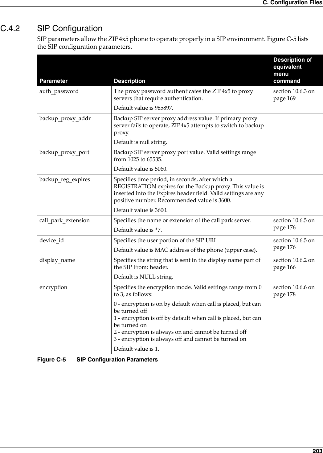
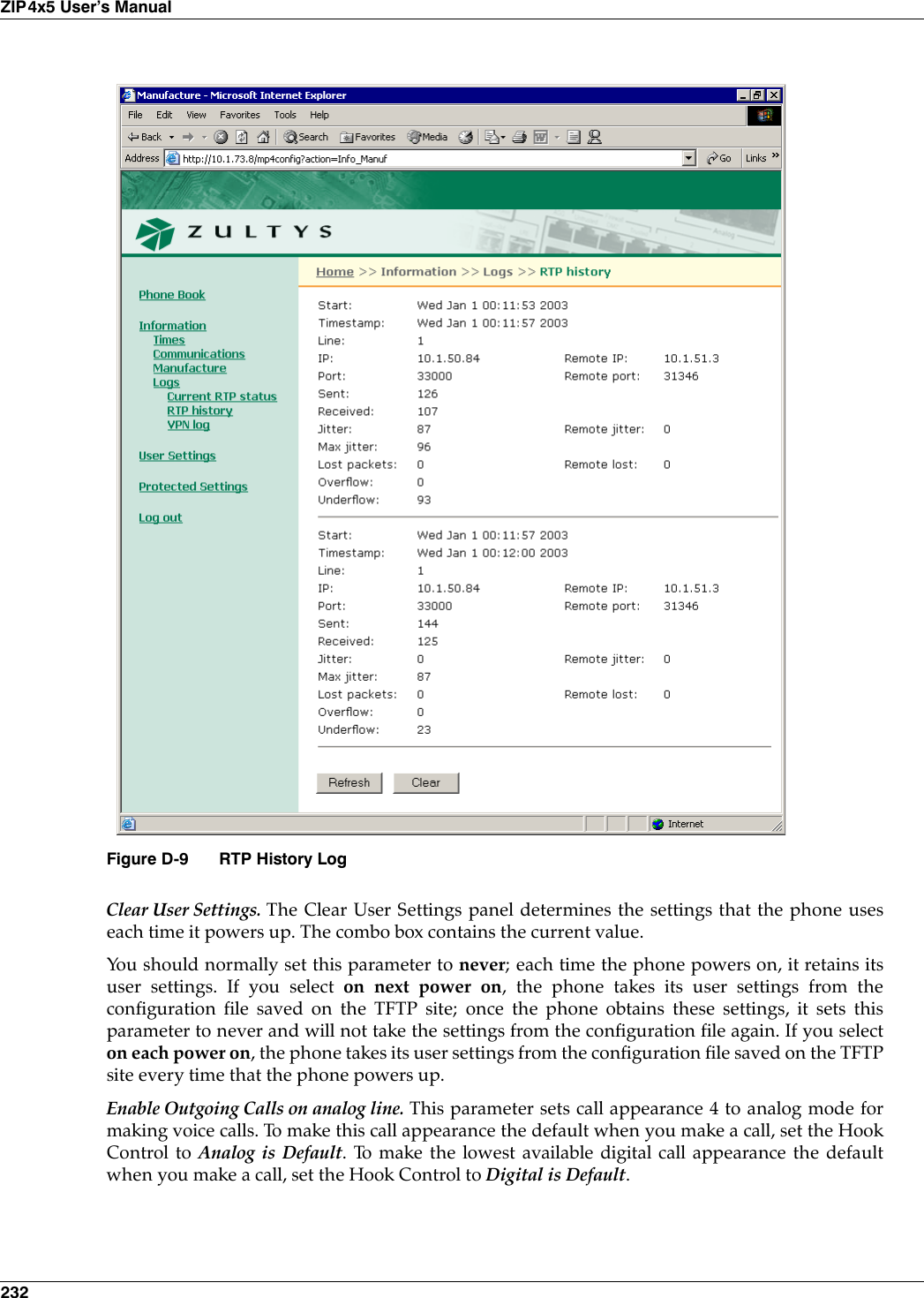
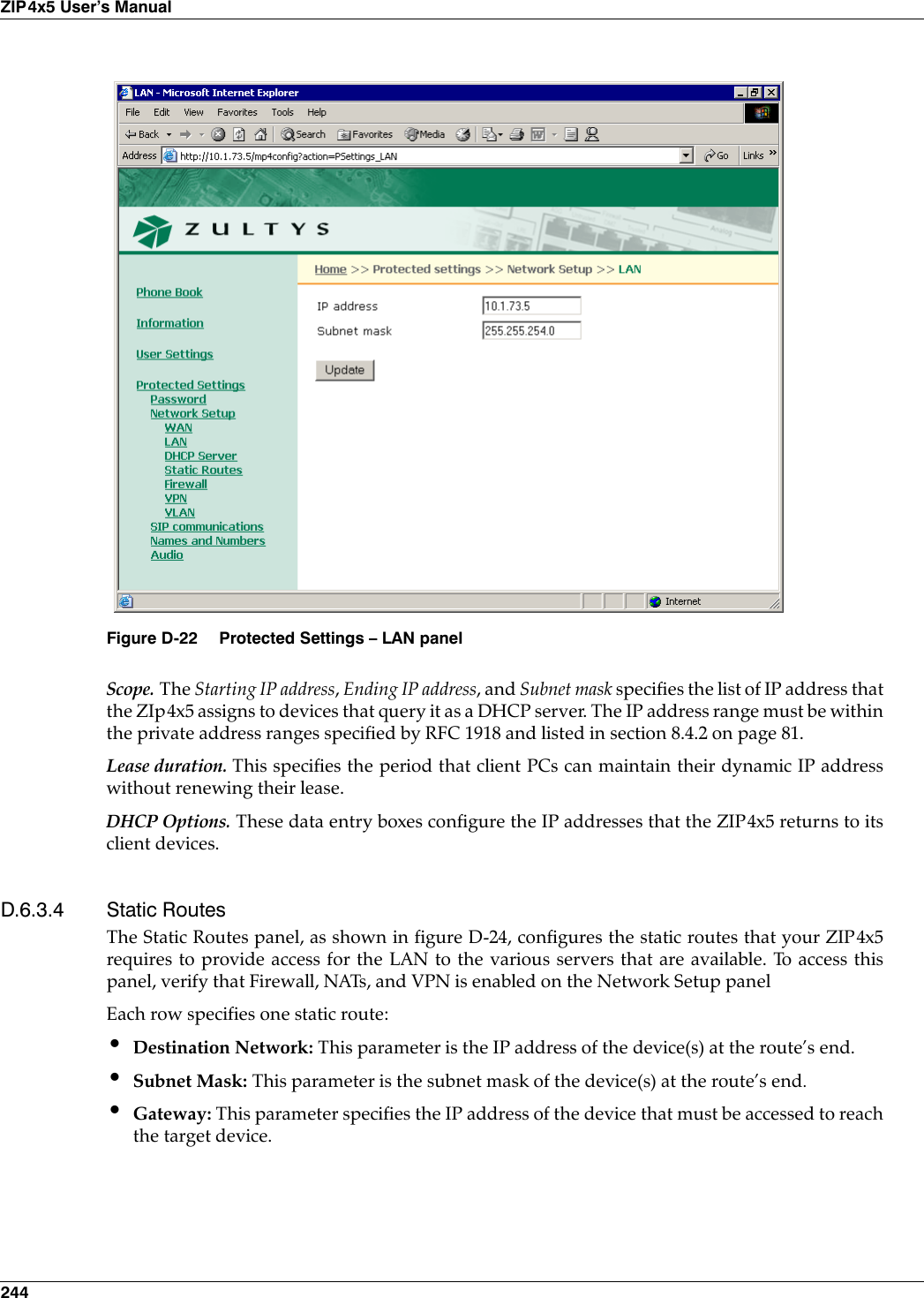
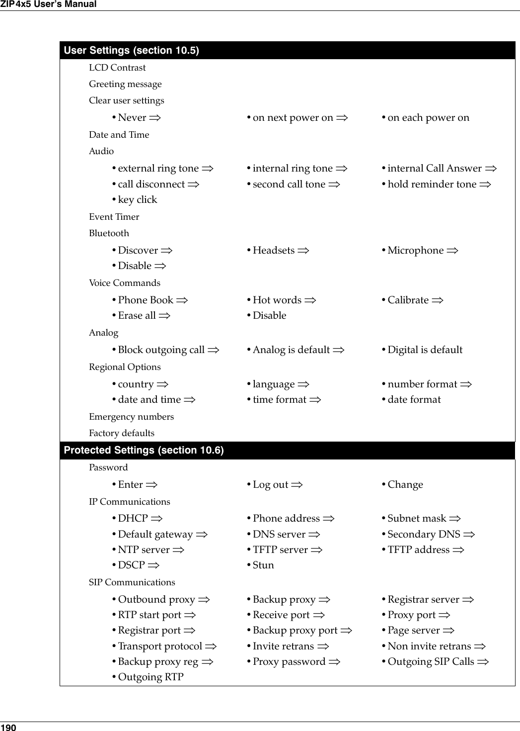
![206ZIP4x5 User’s ManualC.4.2.1 Mandatory FieldsThe proxy_addr parameter must be set in order for the ZIP4x5 phone to send SIP address throughthe proxy server. The proxy server receives SIP requests from the phone and forwards them tothe next intermediate device in the network. This parameter sets the address of the proxy serverfor the phone and provides no meaningful default if it is omitted from the configuration files.C.4.2.2 Sample Configuration File Figure C-6 displays the SIP settings section from a sample configuration file.subscription_expires Specifies time period, in seconds, after which a SUBSCRIBE expires. This value is inserted into the Expires header field. Valid settings are any positive number. Recommended value is 3600.Default value is 3600.use_proxy Enables the sending of SIP requests through the proxy server, which is necessary for normal phone operation. Valid settings are ‘yes’ and ‘no’:‘yes’ - enables option‘no’ - disables optionDefault value is ‘yes’.voice_mail_uri Specifies the name or extension of the voice mail serverDefault value is voice.mail(default uri is *86).section 10.6.5 on page 176[SIP_CONFIG]phone_sip_port=5060rtp_start_port=33000;The Device ID is the user portion of the SIP URIdevice_id=West;The Display Name is sent in SIP messagesdisplay_name=Zultys ZIP4x5;This must always be set to “yes”use_proxy=yesregister_w_proxy=yesproxy_addr=10.1.32.224proxy_port=5060voice_mail_uri=258call_park_extension=259registration_expires=3600Figure C-6 Sample Configuration File – SIP SettingsParameter DescriptionDescription of equivalent menu commandFigure C-5 SIP Configuration Parameters (Continued)](https://usermanual.wiki/Zultys-Technologies/ZIP4X5.Manual-4/User-Guide-458736-Page-18.png)
![210ZIP4x5 User’s Manual[FW]mode=1wan_vid=1lan_vid=2wan_ip=172.32.10.66wan_mask=255.255.240.0;PPPoEpppoe_mode=1pppoe_user=PPPoEpppoe_pwd_1234;FW/NATwan_filters=wanFilter##0.0.0.0/0##1;VPNipsec_mode=1remote_lan_net=172.16.0.0/16remote_wan_ip=180.1.0.50p1_encrypt_algo=3desp1_hash_algo=sha1p1_mode=aggressivepsk=JADEpf_secrecy=0key_lifetime=1 hourencrypt_algo=hmac_md5encrypt_key=0x00authkey=0x00inbound_spi=0x00outbound_spi=0x00my_ident=user_fqdn “my_addy@SQLab.comFigure C-8 Sample Configuration File – Firewall Settings](https://usermanual.wiki/Zultys-Technologies/ZIP4X5.Manual-4/User-Guide-458736-Page-22.png)
![C. Configuration Files 211C.4.4 Hardware ConfigurationHardware configuration parameters adjust LCD and volume characteristics. Figure C-9 lists thehardware configuration parameters.All hardware configuration parameters are optional. Figure C-10 displays the Hardware settingssection from a sample configuration file.Parameter DescriptionDescription of equivalent menu commandhandset_volume Adjusts the handset volume. Values range from 0 (silent) to 20 (loud).Default value is 10.noneheadset_volume Adjusts the headset volume. Values range from 0 (silent) to 20 (loud).Default value is 10.nonelcd_contrast Adjusts the LCD contrast. Values range from 1 (light) to 20 (dark).Default value is 7.section 10.5.1 on page 147ring_volume Adjusts the ringer volume. Values range from 0 (silent) to 20 (loud).Default value is 10.nonespeaker_volume Adjusts the speaker volume. Values range from 0 (silent) to 20 (loud).Default value is 10.noneFigure C-9 Hardware Configuration Parameters[HW_CONFIG]lcd_contrast=8ring_volume=5speaker_volume=5headset_volume=5handset_volume=5Figure C-10 Sample Configuration File – Hardware Configuration Settings](https://usermanual.wiki/Zultys-Technologies/ZIP4X5.Manual-4/User-Guide-458736-Page-23.png)
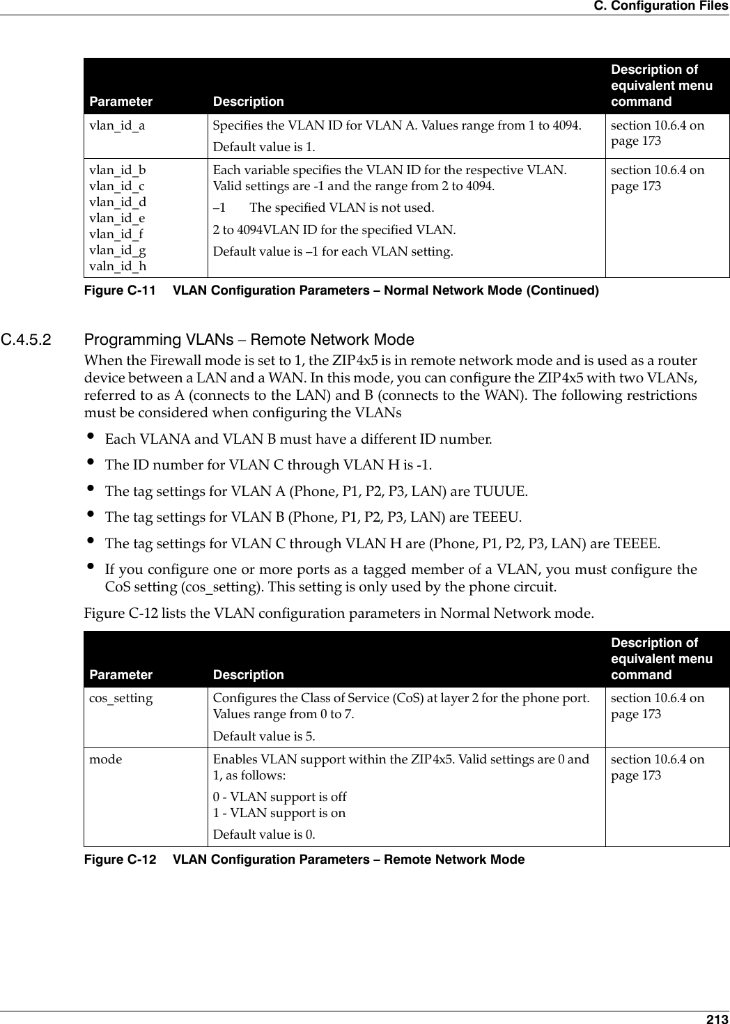
![214ZIP4x5 User’s ManualC.4.5.3 Sample Configuration File Figure C-13 displays the VLAN settings section from a sample configuration file.vlan_id_a Specifies the VLAN ID for VLAN A, which connects the LAN to the ZIP4x5. Values range from 1 to 4095.Default value is 1.section 10.6.4 on page 173vlan_id_b Specifies the VLAN ID for VLAN B, which connect the WAN to the ZIP4x5. Values range from 1 to 4095.Default value is 2.section 10.6.4 on page 173[VLAN_CONFIG]mode=1vlan_id_a=1circuits_a=UUUUUvlan_id_b=-1circuits_b=EEEEEvlan_id_c=-1circuits_c=EEEEEvlan_id_d=-1circuits_d=EEEEEvlan_id_e=-1circuits_e=EEEEEvlan_id_f=-1circuits_f=EEEEEvlan_id_g=-1circuits_g=EEEEEvlan_id_h=-1circuits_h=EEEEEcos_setting=5Figure C-13 Sample Configuration File – VLAN Configuration SettingsParameter DescriptionDescription of equivalent menu commandFigure C-12 VLAN Configuration Parameters – Remote Network Mode (Continued)](https://usermanual.wiki/Zultys-Technologies/ZIP4X5.Manual-4/User-Guide-458736-Page-26.png)
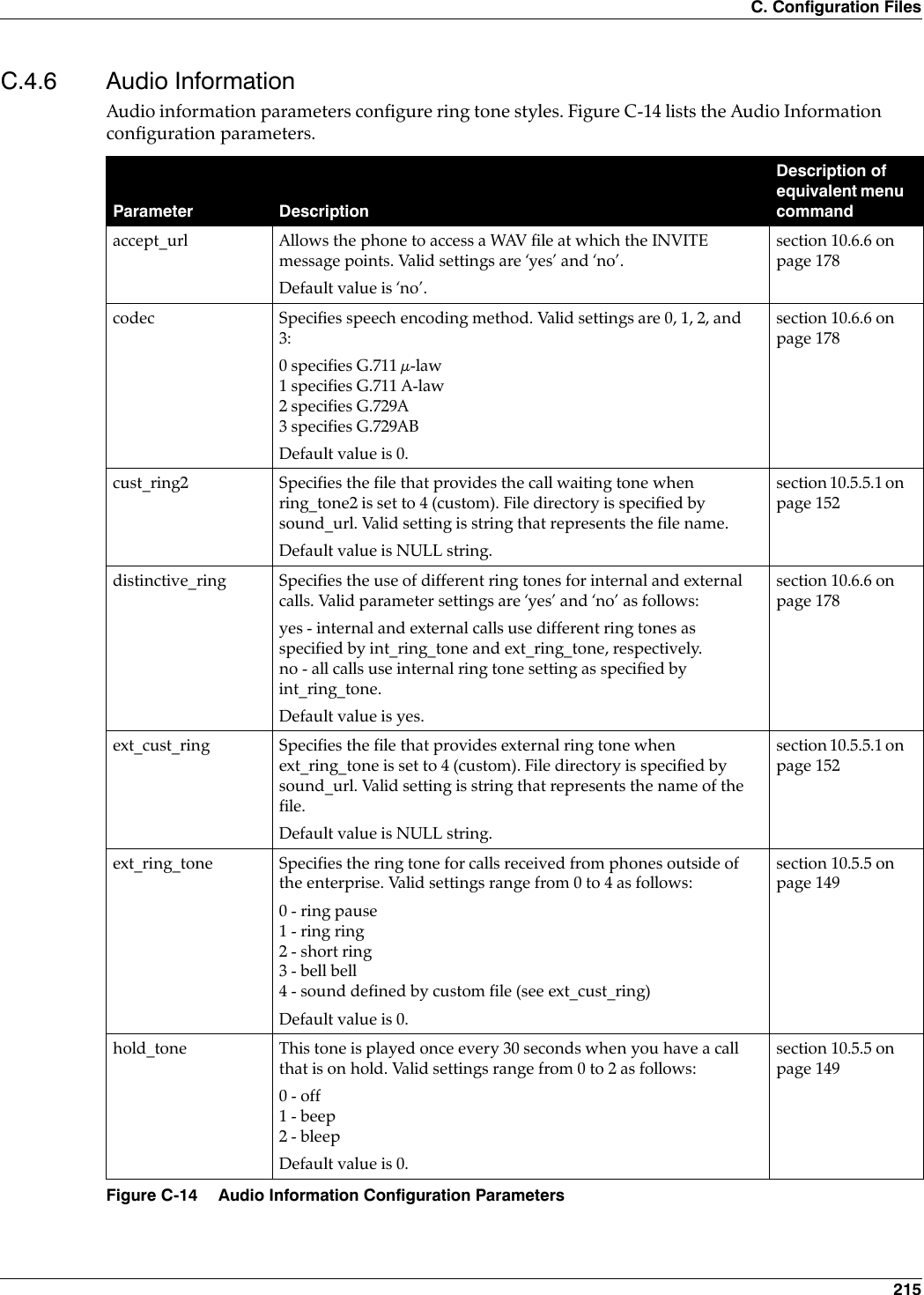
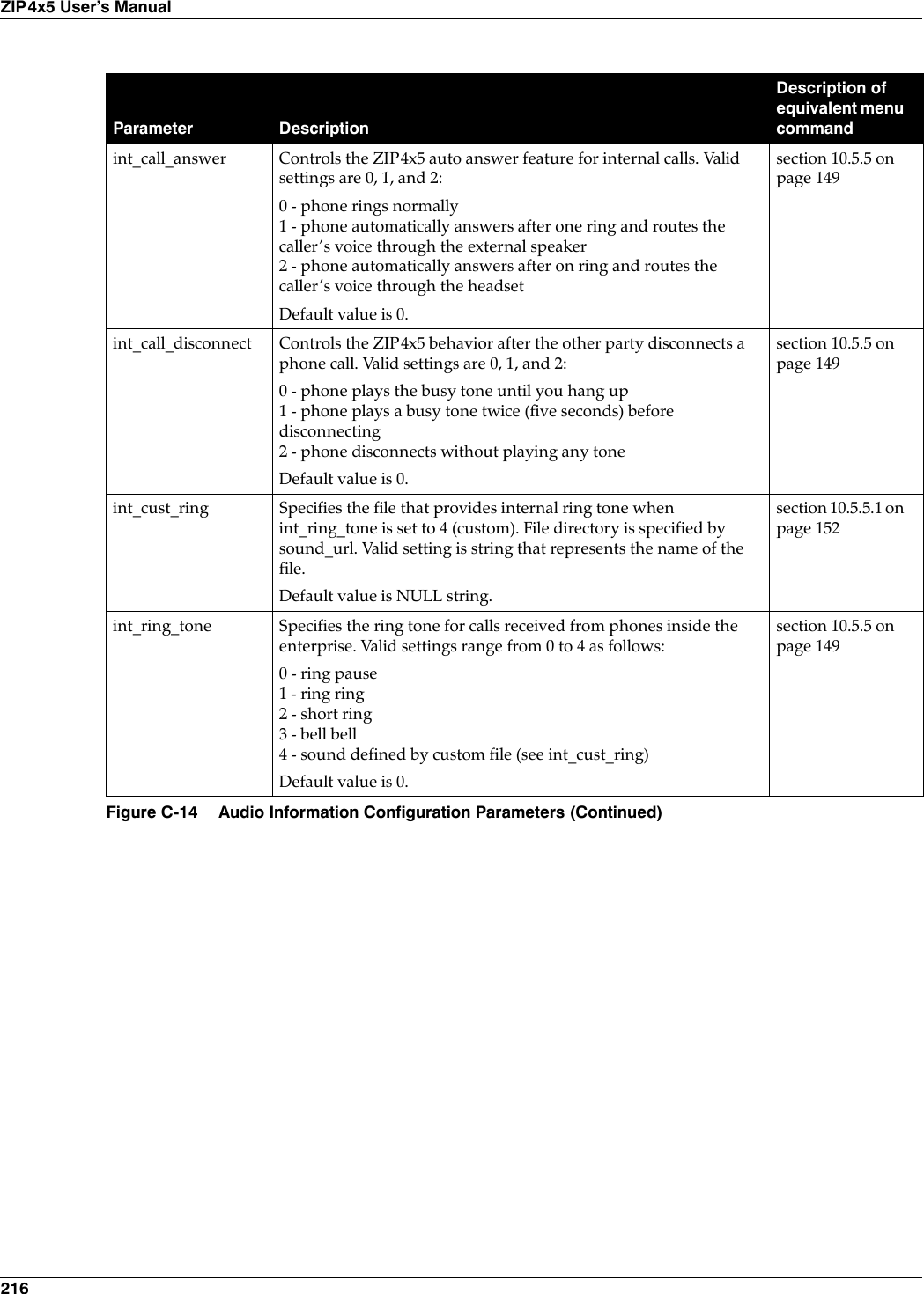
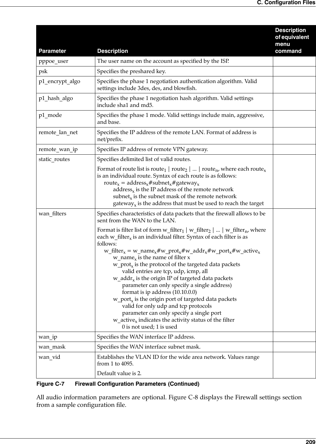
![C. Configuration Files 217All audio information parameters are optional. Figure C-15 displays the Audio Informationsettings section from a sample configuration file.key_click Specifies the tone that the phone emits when you press a button or a non numeric key. Valid settings range from 0 to 3 as follows:0 - off1 - click2 - beep3 - bleepDefault value is 0.section 10.5.5 on page 149ring_tone2 Specifies the call waiting tone that is played when you are talking on the phone and the phone receives another call. Valid settings range from 0 to 5 as follows:0 - short high beep1 - long high beep2 - short low beep3 - long low beep4 - sound defined by custom file (see cust_ring2)5 - silentDefault value is 0.section 10.5.5 on page 149sound_url Specifies the http directory location for files that define custom ring tones. Valid setting is http://<name of directory>Default value is http://www.zultys.com/phone_sounds/section 10.6.6 on page 178[AUDIO_INFO]ext_ring_tone=0ext_cust_ring=int_ring_tone=0int_cust_ring=ring_tone2=0cust_ring2=key_click=0codec=0distinctive_ring=yessound_url=Figure C-15 Sample Configuration File – Audio Information SettingsParameter DescriptionDescription of equivalent menu commandFigure C-14 Audio Information Configuration Parameters (Continued)](https://usermanual.wiki/Zultys-Technologies/ZIP4X5.Manual-4/User-Guide-458736-Page-29.png)
![218ZIP4x5 User’s ManualC.4.7 DHCP Server ConfigurationFirewall configuration parameters define settings required by the ZIP4x5 to act as a DHCP server.All audio information parameters are optional. Figure C-17 displays the DHCP Server settingssection from a sample configuration file.Parameter DescriptionDescription of equivalent menu commandmode Enables the ZIP4x5 to act as a DHCP server. Valid settings are 0 and 1 as follows:0 - server functions are off.1 - server functions are on.start_ip Specifies the starting IP address for DHCP scope.end_ip Specifies the ending IP address for DHCP scope. o_mask Specifies the subnet mask for the DHCP scope.lease_secs Specifies the lease duration, in seconds.o_router Specifies the IP address of the default gateway.o_dns1 Specifies the IP address of the primary DNS server.o_dns2 Specifies the IP address of the secondary DNS server.o_dns3 Specifies the IP address of the tertiary DNS server.o_domain Specifies the default domain nameo_ntp1 Specifies the IP address of the primary NTP server.o_ntp2 Specifies the IP address of the secondary NTP server.o_ntp3 Specifies the IP address of the tertiary NTP server.o_tftp Specifies the IP address of the TFTP server.Figure C-16 Firewall Configuration Parameters[DHCP_SRV]mode=1start_ip=172.16.17.0end_ip=172.16.31.254o_mask=255.255.240.0lease_secs=300o_router=172.16.16.66o_dns1=o_dns2=o_dns3=o_domain=o_ntp1=172.16.16.66o_ntp1=o_ntp2=o_ntp3=Figure C-17 Sample Configuration File – DHCP Server](https://usermanual.wiki/Zultys-Technologies/ZIP4X5.Manual-4/User-Guide-458736-Page-30.png)
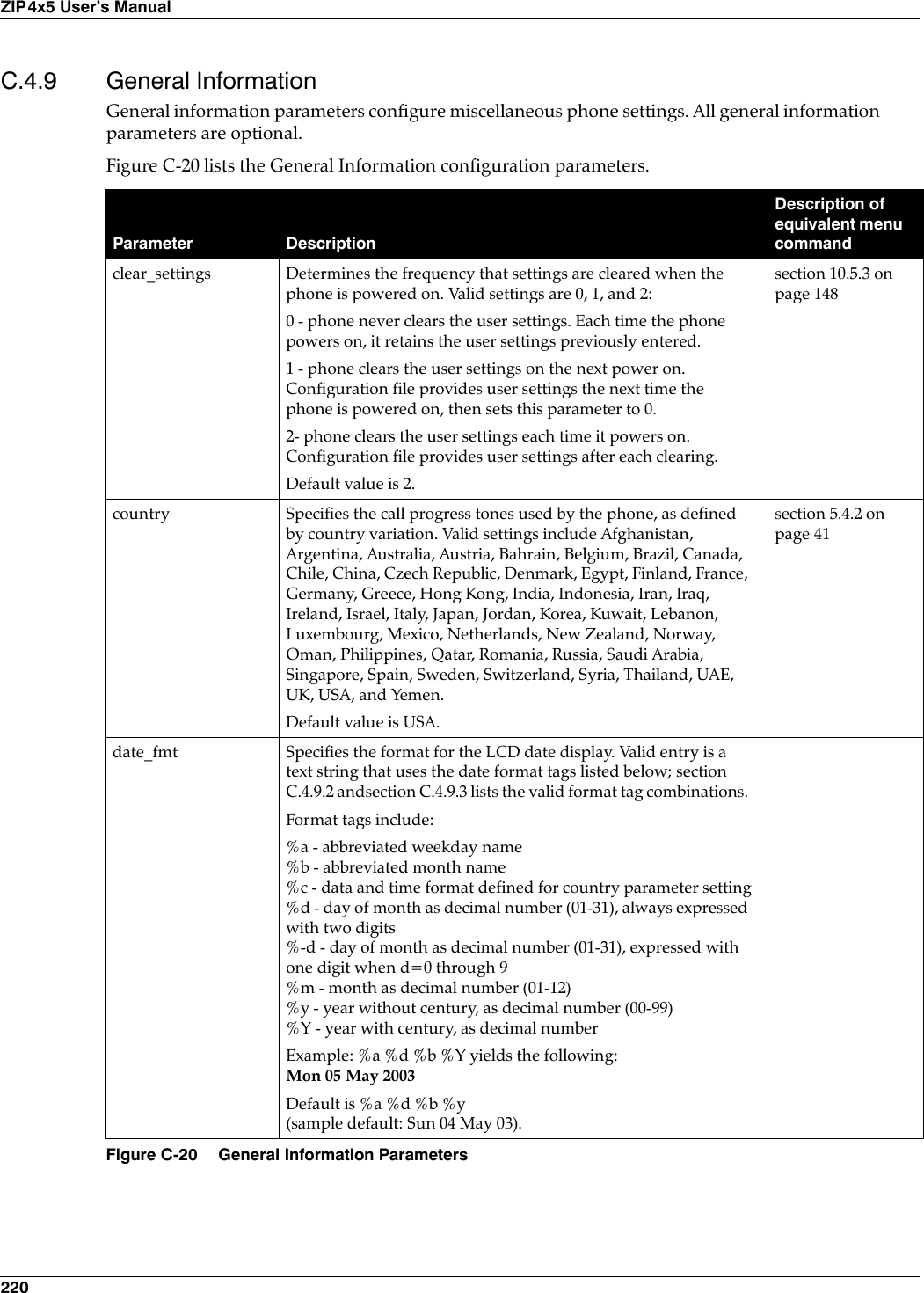
![C. Configuration Files 219C.4.8 Bluetooth ConfigurationFirewall configuration parameters define settings required by the ZIP4x5 to use Bluetoothaccessories.Bluetooth parameters are optional. Figure C-19 displays the Bluetooth settings section from asample configuration file.Parameter DescriptionDescription of equivalent menu commandmode Enables the ZIP4x5 to use Bluetooth. Valid settings are 0 and 1, as follows:0 - Bluetooth is disabled1 - Bluetooth is enabledDefault value is 0.Figure C-18 Firewall Configuration Parameters[BT]mode=1Figure C-19 Sample Configuration File – Bluetooth](https://usermanual.wiki/Zultys-Technologies/ZIP4X5.Manual-4/User-Guide-458736-Page-31.png)
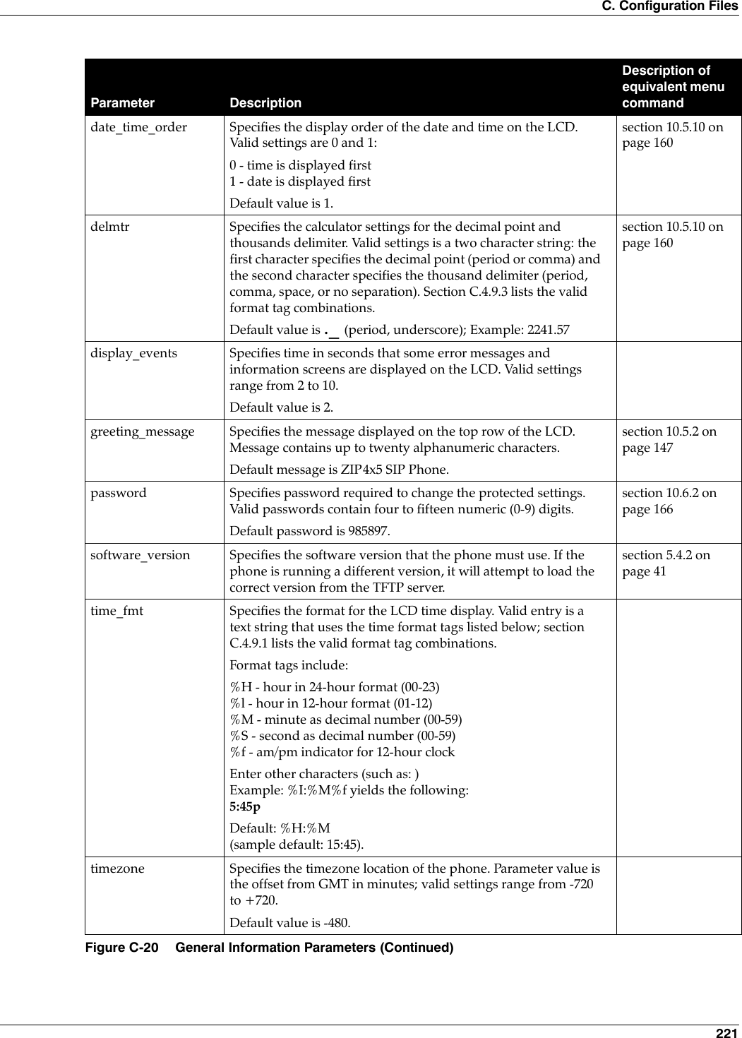
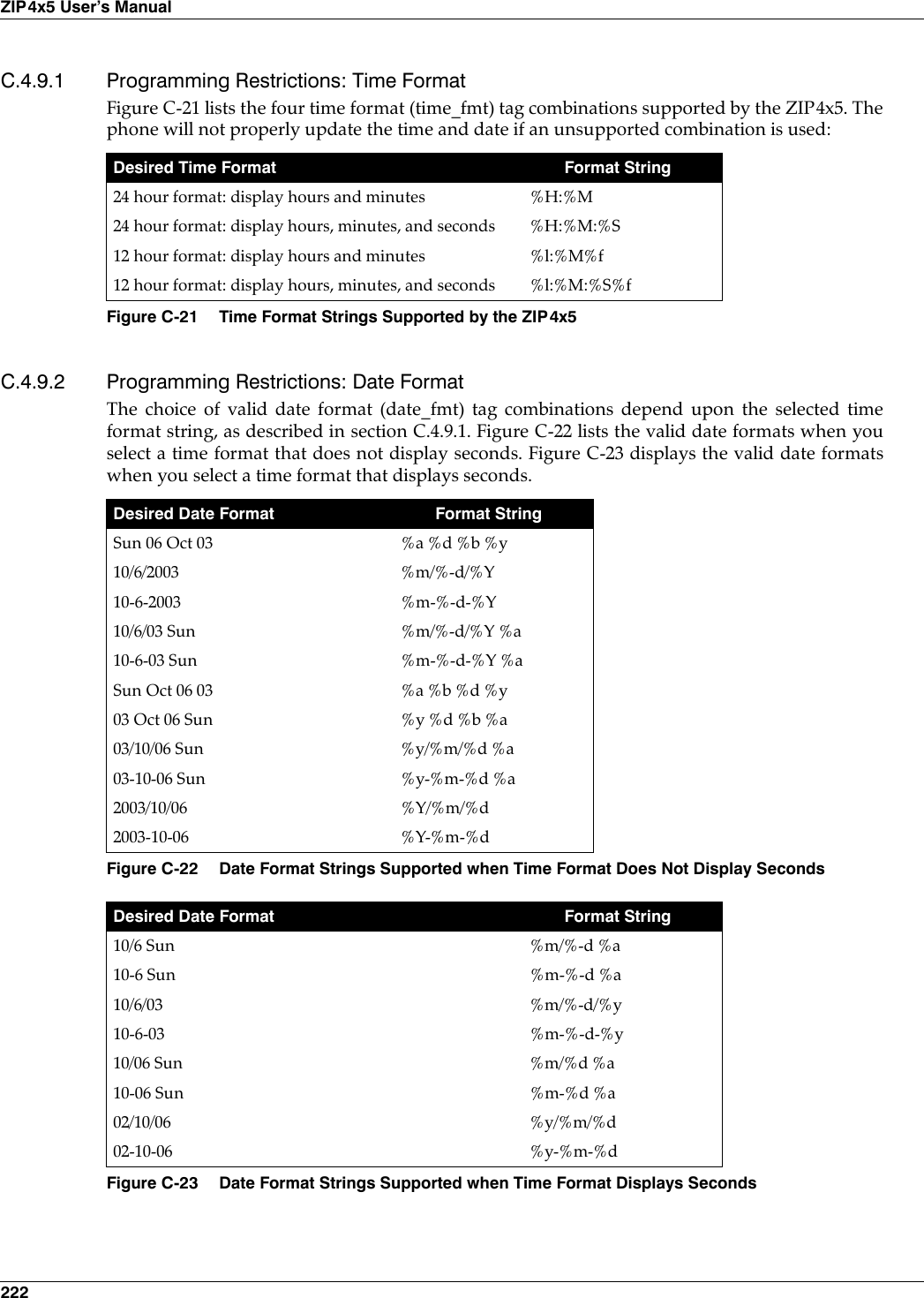
![C. Configuration Files 223C.4.9.3 Programming Restrictions: Delimiter FormatThe delimiters format configure the appearance of numbers as used in the calculator. Eachdelimiter string comprises two characters. The first character specifies the decimal point – eithera period (.) or a comma (,). The second character specifies the thousands delimiter; selectionoption include a comma (,), period (.), a space ( ), or no separation between the characters, whichis denoted by an underscore (_).Figure C-24 lists the six delimeter format (delmtr) tag combinations supported by the ZIP4x5. Thecalculator may not function properly if an unsupported combination is used: C.4.9.4 Sample Configuration File Figure C-25 displays the Audio Information settings section from a sample configuration file.Sun 06 Oct (supported only for 24 hour time format) %a %d %bSun Oct 06 (supported only for 24 hour time format) %a %b %dOct 06 Sun (supported only for 24 hour time format) %b %d %aDesired Number Format Delimiter String1,234.99 “.,” (period, comma)1.234,99 “,.” (comma, period)1 234.99 “. “ (period, space)1 234,99 “, “ (comma, space)1234.99 “._“ (period, underscore)1234,99 “,_“ (comma, underscore)Figure C-24 Time Format Strings Supported by the ZIP4x5[GENERAL_INFO]software_version=1.0.0;The message displayed on the LCD in idle modegreeting_message=ZIP 4x5 SIP Phonepassword=985897time_fmt=%H:%Mdate_fmt=%a %d %b %ydate_time_order=0;This is the offset from GMT, in minutestimezone=-480country=USAlanguage=ENGLISHdelmtr=._clear_settings=2Figure C-25 Sample Configuration File – General Information SettingsDesired Date Format Format StringFigure C-23 Date Format Strings Supported when Time Format Displays Seconds](https://usermanual.wiki/Zultys-Technologies/ZIP4X5.Manual-4/User-Guide-458736-Page-35.png)