Chamberlain Group The 8389 Overhead Door and Gate Operator User Manual 01 37718 indd
Chamberlain Group Inc, The Overhead Door and Gate Operator 01 37718 indd
Contents
- 1. User Manual_20160711_v1 - User Manual pt1 HCTDCU
- 2. User Manual_20160711_v1 - User Manual pt2 HCTDCU
- 3. User Manual_20160711_v1 - User Manual pt3 HCTDCU
- 4. User Manual_20160711_v1 - User Manual pt4 HCTDCU
- 5. User Manual_20160711_v1 - User Manual pt5 HCTDCU
- 6. User Manual_20160711_v1 - User Manual pt6 HCTDCU
- 7. User Manual_20160711_v1 - User Manual pt7 HCTDCU
- 8. User Manual_20160711_v1 - User Manual pt8 HCTDCU
User Manual_20160711_v1 - User Manual pt1 HCTDCU

COMMERCIAL 24VDC HIGH TRAFFIC
OVERHEAD DOOR AND GATE OPERATOR
WITH BATTERY BACKUP
Model HCTDCU
INSTALLATION MANUAL
LiftMaster
845 Larch Avenue
Elmhurst, IL 60126-1196
• THIS PRODUCT IS TO BE INSTALLED AND SERVICED BY A
TRAINED TECHNICIAN ONLY.
• This model is for use on vehicular passage gates or
commercial doors ONLY and not intended for use on
pedestrian passage gates.
• Install the operator at least 8 feet (2.4 m) above the floor.
• This model is intended for use in Class II, III and IV vehicular
trolley gate or commercial door applications.
• Visit LiftMaster.com to locate a professional installing dealer
in your area.
• This gate/door operator is compatible with MyQ® and
Security+ 2.0® accessories.
Register your operator to receive
updates and offers from LiftMaster
Take a photo of the camera icon
including the points ( ).
Send it in by texting the photo to 71403
(US) or visit www.liftmaster.photo
(Global)
HCTDCU
Motor Unit
HCT08
8 Foot Rail
HCT10
10 Foot Rail
HCT12
12 Foot Rail
PHOTOREGISTER
SM
LM-HCTROLLEY

2
SAFETY
SAFETY SYMBOL AND SIGNAL WORD REVIEW
When you see these Safety Symbols and Signal Words on the following pages,
they will alert you to the possibility of Serious Injury or Death if you do not
comply with the warnings that accompany them. The hazard may come from
something mechanical or from electric shock. Read the warnings carefully.
When you see this Signal Word on the following pages, it will alert you to the
possibility of damage to your gate/door and/or the gate/door operator if you do
not comply with the cautionary statements that accompany it. Read them
carefully.
IMPORTANT NOTE:
• BEFORE attempting to install, operate or maintain the operator, you must
read and fully understand this manual and follow all safety instructions.
• Operator intended to be installed on a properly balanced gate/door only. Make
sure gate/door is properly balanced before installing.
• DO NOT attempt repair or service of your operator unless you are an
Authorized Service Technician.
TABLE OF CONTENTS
SAFETY 2
SAFETY SYMBOL AND SIGNAL WORD REVIEW ..................................2
USAGE CLASS .......................................................................................3
UL325 ENTRAPMENT PROTECTION REQUIREMENTS ..........................3
SAFETY INSTALLATION INFORMATION ................................................4
GATE CONSTRUCTION INFORMATION ..................................................5
INTRODUCTION 6
CARTON INVENTORY ............................................................................6
OPERATOR SPECIFICATIONS ................................................................7
OVERVIEW OF TYPICAL INSTALLATION ...............................................8
INSTALLATION 9
IMPORTANT SAFETY INFORMATION ....................................................9
CONNECT RAIL TO OPERATOR ...........................................................10
INSTALL VENTED PLUG ......................................................................11
DETERMINE LOCATION FOR OPERATOR ............................................11
MOUNT THE OPERATOR .....................................................................12
INSTALL ENTRAPMENT PROTECTION ................................................13
WIRING 15
POWER WIRING ..................................................................................15
CONNECT BATTERIES .........................................................................16
ADJUSTMENT 17
LIMIT AND FORCE ADJUSTMENT .......................................................17
OBSTRUCTION TEST ...........................................................................18
OPERATOR OVERVIEW 19
PROGRAMMING 20
REMOTE CONTROLS (NOT PROVIDED) ..............................................20
LIFTMASTER INTERNET GATEWAY (NOT PROVIDED) .......................21
ERASE ALL CODES ..............................................................................21
ERASE LIMITS .....................................................................................21
TO REMOVE AND ERASE MONITORED ENTRAPMENT
PROTECTION DEVICES ........................................................................21
LIMIT SETUP WITH A REMOTE CONTROL ..........................................22
OPERATION 23
GATE/DOOR OPERATOR SETUP EXAMPLES .......................................23
CONTROL BOARD OVERVIEW .............................................................24
RESET BUTTON ...................................................................................25
OPERATOR ALARM .............................................................................25
ADJUSTABLE OPEN SPEED .................................................................25
REMOTE CONTROL .............................................................................25
MANUAL DISCONNECT .......................................................................26
ACCESSORY WIRING 27
EXTERNAL CONTROL DEVICES ...........................................................27
EXTERNAL RESET BUTTON .................................................................27
MISCELLANEOUS WIRING ..................................................................28
EXPANSION BOARD 29
EXPANSION BOARD OVERVIEW .........................................................29
AUXILIARY RELAYS ............................................................................30
WIRING ACCESSORIES TO THE EXPANSION BOARD .........................31
MAINTENANCE 32
IMPORTANT SAFETY INFORMATION ..................................................32
MAINTENANCE CHART ........................................................................32
BATTERIES ..........................................................................................32
TROUBLESHOOTING 33
DIAGNOSTIC CODES ...........................................................................33
CONTROL BOARD LEDS ......................................................................36
TROUBLESHOOTING CHART ...............................................................37
WIRING DIAGRAM 40
REPAIR PARTS 41
ACCESSORIES 42
WARRANTY 44
MECHANICAL
ELECTRICAL
3
The same type of device shall not be used for both entrapment
protection means. Use of a single device to cover both the opening
and closing directions is in accordance with the requirement;
however, a single device is not required to cover both directions.
This operator is provided with Type A. The installer is required to
install additional entrapment protection devices in each entrapment
zone.
HORIZONTAL SLIDE AND SWING GATE OPERATOR
GATE OPERATOR ENTRAPMENT PROTECTION TYPES
Type A Inherent (built into the operator) entrapment
protection system
Type B1 Non-contact sensors such as photoelectric sensors
Type B2 Contact sensors such as edge sensors
SAFETY
UL325 ENTRAPMENT PROTECTION REQUIREMENTS
This vehicular gate/door operator must be installed with at least two independent entrapment protection means as specified in the table below.
To reduce the risk of SEVERE INJURY or DEATH:
• READ AND FOLLOW ALL INSTRUCTIONS.
• NEVER let children operate or play with gate/door controls. Keep
remote controls away from children.
• ALWAYS keep people and objects away from the gate/door. NO ONE
SHOULD CROSS THE PATH OF THE MOVING GATE/DOOR.
• Test the gate/door operator monthly. The gate/door MUST reverse
on contact with a rigid object or reverse when an object activates the
non-contact sensors. After adjusting the force or the limit of travel,
retest the gate/door operator. Failure to adjust and retest the
operator properly can increase the risk of severe INJURY or DEATH.
• Use the emergency release ONLY when the gate/door is closed. Use
caution when using this release when the gate/door is open. Weak or
broken springs may cause the gate/door to fall rapidly, causing
severe INJURY or DEATH.
• KEEP GATES/DOORS PROPERLY OPERATING AND BALANCED.
Read the gate/door manufacturer's owner’s manual. An improperly
operating or balanced gate/door could cause severe INJURY or
DEATH. Have a qualified service person make repairs to gate/door
hardware. Have trained gate/door systems technician make repairs
to cables, spring assemblies, and other hardware.
• The entrance is for vehicles ONLY. Pedestrians MUST use separate
entrance.
• SAVE THESE INSTRUCTIONS.
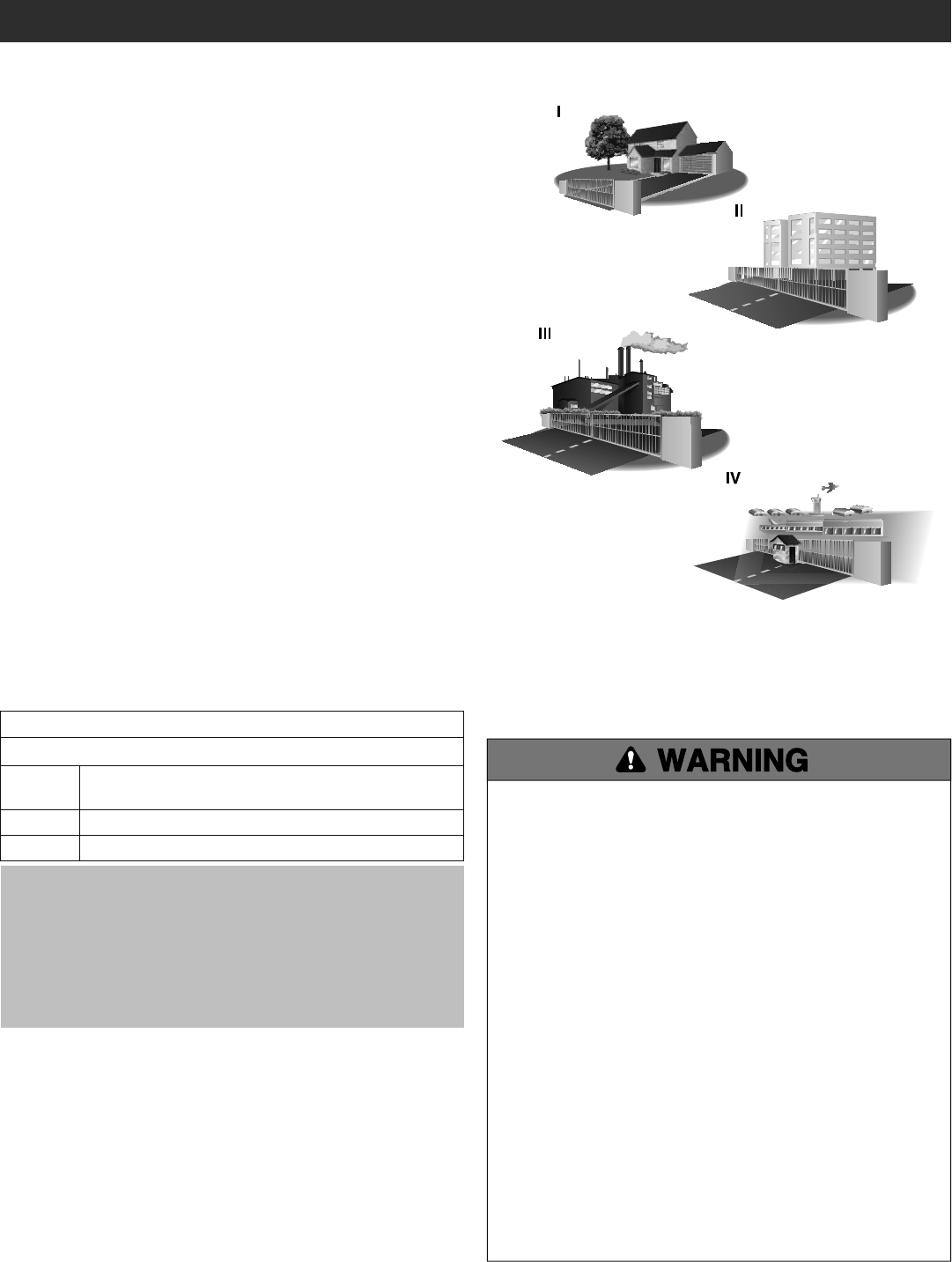
USAGE CLASS
IMPORTANT SAFETY INFORMATION
CLASS I – RESIDENTIAL VEHICULAR GATE
OPERATOR
A vehicular gate operator (or system) intended for use in garages or
parking areas associated with a residence of one-to four single families.
CLASS II – COMMERCIAL/GENERAL ACCESS
VEHICULAR GATE OPERATOR
A vehicular gate operator (or system) intended for use in a commercial
location or building such as a multi-family housing unit (five or more
single family units), hotel, garages, retail store, or other buildings
accessible by or servicing the general public.
CLASS III – INDUSTRIAL/LIMITED ACCESS
VEHICULAR GATE OPERATOR
A vehicular gate operator (or system) intended for use in an industrial
location or building such as a factory or loading dock area or other
locations not accessible by or intended to service the general public.
CLASS IV– RESTRICTED ACCESS VEHICULAR GATE
OPERATOR
A vehicular gate operator (or system) intended for use in a guarded
industrial location or building such as an airport security area or other
restricted access locations not servicing the general public, in which
unauthorized access is prevented via supervision by security personnel.

4
1. Vehicular gate systems provide convenience and security. Gate
systems are comprised of many component parts. The gate
operator is only one component. Each gate system is specifically
designed for an individual application.
2. Gate operating system designers, installers and users must take
into account the possible hazards associated with each individual
application. Improperly designed, installed or maintained systems
can create risks for the user as well as the bystander. Gate systems
design and installation must reduce public exposure to potential
hazards.
3. A gate operator can create high levels of force in its function as a
component part of a gate system. Therefore, safety features must
be incorporated into every design. Specific safety features include:
• Edges Sensors (contact) • Guards for Exposed Rollers
• Photoelectric Sensors • Screen Mesh
• Vertical Posts • Instructional and Precautionary Signage
4. Install the gate operator only when:
a. The operator is appropriate for the construction and the usage
class of the gate.
b. All openings of a horizontal slide gate are guarded or screened
from the bottom of the gate to a minimum of 6 feet (1.8 m)
above the ground to prevent a 2-1/4 inches (6 cm) diameter
sphere from passing through the openings anywhere in the gate,
and in that portion of the adjacent fence that the gate covers in
the open position.
c. All exposed pinch points are eliminated or guarded, and guarding
is supplied for exposed rollers.
5. The operator is intended for installation only on gates used for
vehicles. Pedestrians must be supplied with a separate access
opening. The pedestrian access opening shall be designed to
promote pedestrian usage. Locate the gate such that persons will
not come in contact with the vehicular gate during the entire path of
travel of the vehicular gate.
6. The gate must be installed in a location so that enough clearance is
supplied between the gate and adjacent structures when opening
and closing to reduce the risk of entrapment. Swinging gates shall
not open into public access areas.
7. The gate must be properly installed and work freely in both
directions prior to the installation of the gate operator.
8. Controls intended for user activation must be located at least 6 feet
(1.8 m) away from any moving part of the gate and where the user
is prevented from reaching over, under, around or through the gate
to operate the controls. Outdoor or easily accessible controls shall
have a security feature to prevent unauthorized use.
Exception: Emergency access controls only accessible by authorized
personnel (e.g. fire, police) may be placed at any location in the
line-of-sight of the gate.
9. The Stop and/or Reset (if provided separately) must be located in
the line-of-sight of the gate. Activation of the reset control shall not
cause the operator to start.
10. A minimum of two (2) WARNING SIGNS shall be installed, one on
each side of the gate where easily visible.
11. For a gate operator utilizing a non-contact sensor:
a. Reference owner’s manual regarding placement of non-contact
sensor for each type of application. See Install Entrapment
Protection section.
b. Care shall be exercised to reduce the risk of nuisance tripping,
such as when a vehicle trips the sensor while the gate is still
moving.
c. One or more non-contact sensors shall be located where the risk
of entrapment or obstruction exists, such as the perimeter
reachable by a moving gate or barrier.
12. For a gate operator utilizing a contact sensor such as an edge
sensor:
a. One or more contact sensors shall be located where the risk of
entrapment or obstruction exists, such as at the leading edge,
trailing edge and post mounted both inside and outside of a
vehicular horizontal slide gate.
b. A hard wired contact sensor shall be located and its wiring
arranged so the communication between the sensor and the gate
operator is not subject to mechanical damage.
c. A wireless device such as one that transmits radio frequency (RF)
signals to the gate operator for entrapment protection functions
shall be located where the transmission of the signals are not
obstructed or impeded by building structures, natural
landscaping or similar obstruction. A wireless device shall
function under the intended end-use conditions.
d. One or more contact sensors shall be located on the inside and
outside leading edge of a swing gate. Additionally, if the bottom
edge of a swing gate is greater than 6 inches (152 mm) above
the ground at any point in its arc of travel, one or more contact
sensors shall be located on the bottom edge.
e. One or more contact sensors shall be located at the bottom edge
of a vertical barrier (arm).
f. One or more contact sensors shall be located at the bottom edge
of a vehicular vertical lift gate.
g. One or more contact sensors shall be located at the pinch point of
a vehicular vertical pivot gate.
SAFETY INSTALLATION INFORMATION
SAFETY

5
1. GENERAL REQUIREMENTS
1.1 Gates shall be constructed in accordance with the provisions
given for the appropriate gate type listed, refer to ASTM F2200 for
additional gate types.
1.2 Gates shall be designed, constructed and installed to not fall over
more than 45 degrees from the vertical plane, when a gate is
detached from the supporting hardware.
1.3 Gates shall have smooth bottom edges, with vertical bottom
edged protrusions not exceeding 0.50 inches (12.7 mm) when
other than the exceptions listed in ASTM F2200.
1.4 The minimum height for barbed tape shall not be less than 8 feet
(2.44 m) above grade and for barbed wire shall not be less than 6
feet (1.83 m) above grade.
1.5 An existing gate latch shall be disabled when a manually operated
gate is retrofitted with a powered gate operator.
1.6 A gate latch shall not be installed on an automatically operated
gate.
1.7 Protrusions shall not be permitted on any gate, refer to ASTM
F2200 for Exceptions.
1.8 Gates shall be designed, constructed and installed such that their
movement shall not be initiated by gravity when an automatic
operator is disconnected, in accordance with the following.
1.8.1 Vehicular horizontal slide gate. Shall not result in continuous,
unimpeded movement in either lineal direction of its travel.
1.8.2 Vehicular horizontal swing gate. Shall not result in continuous,
unimpeded movement in either direction along the arc of its path
of travel.
1.9 For pedestrian access in the vicinity of an automated vehicular
gate, a separate pedestrian gate shall be provided. The pedestrian
gate shall be installed in a location such that a pedestrian shall
not come in contact with a moving vehicular access gate. A
pedestrian gate shall not be incorporated into an automated
vehicular gate panel.
2. SPECIFIC APPLICATIONS
2.1 Any non-automated gate that is to be automated shall be
upgraded to conform to the provisions of this specification.
2.2 This specification shall not apply to gates generally used for
pedestrian access and to vehicular gates not to be automated.
2.3 Any existing automated gate, when the operator requires
replacement, shall be upgraded to conform to the provisions of
this specification in effect at that time.
3. VEHICULAR VERTICAL LIFT GATES
3.1 The following provisions shall apply to Class I, Class II and Class
III vehicular vertical lift gates:
3.1.1 All openings shall be designed, guarded or screened to prevent a
4 in. (102 mm) diameter sphere from passing through the
openings anywhere in the gate.
3.1.2 A gap, measured in the horizontal plane parallel to the roadway,
between a fixed stationary object nearest the roadway (such as a
gate support post) and the gate frame when the gate is in either
the fully open position or the fully closed position, shall not
exceed 4 in. (102 mm).
Exception: All other fixed stationary objects greater than 16 in.
(406 mm) from the gate frame shall not be required to comply
with this section.
3.1.3 Horizontal and vertical framing members of a gate shall be
smooth, and shall not include horizontal protrusions other than
gate hardware.
GATE CONSTRUCTION INFORMATION
Vehicular gates should be installed in accordance with ASTM F2200: Standard Specification for Automated Vehicular Gate Construction. For a copy,
contact ASTM directly at 610-832-9585 or www.astm.org.
3.1.4 A positive stop shall be required to limit travel to the designed
fully open position.
3.2 Class IV vehicular vertical lift gates shall be designed, constructed
and installed in accordance with security related parameters
specific to the application in question.
4. VEHICULAR VERTICAL PIVOT GATES
4.1 The following provisions shall apply to Class I, Class II, and Class
III vehicular vertical pivot gates:
4.1.1 All areas of the moving gate panel from the bottom of the gate to
the top of the gate or a minimum of 72 in. (1.83 m) above grade,
whichever is less, that pass by a fixed stationary object, and in
the area of the adjacent fence that the gate covers during the
travel of the gate, shall be designed, guarded or screened to
prevent a 2 1⁄4 in. (57 mm) diameter sphere from passing
through such areas.
4.1.2 A gap, measured in the horizontal plane parallel to the roadway,
between a fixed stationary object nearest the roadway (such as a
gate support post) and the gate frame when the gate is in either
the fully open position or the fully closed position, shall not
exceed 4 in. (102 mm).
Exception: All other fixed stationary objects greater than 16 in.
(406 mm) from the gate frame shall not be required to comply
with this section.
4.1.3 Horizontal and vertical framing members of a gate shall be
smooth, and shall not include protrusions other than gate
hardware.
4.1.4 All gates shall be designed with sufficient lateral stability to
assure that the gate will enter a receiver guide.
4.2 Class IV vehicular vertical pivot gates shall be designed,
constructed and installed in accordance with security related
parameters specific to the application in question.
5. VEHICULAR OVERHEAD PIVOT GATES
5.1 The following provisions shall apply to Class I, Class II and Class
III vehicular overhead pivot gates:
5.1.1 All weight bearing exposed rollers 8 ft (2.44 m), or less, above
grade shall be guarded or covered.
5.1.2 All openings shall be designed, guarded or screened to prevent a
4 in. (102 mm) diameter sphere from passing through the
openings anywhere in the gate.
5.1.3 A gap, measured in the horizontal plane parallel to the roadway,
between a fixed stationary object nearest the roadway (such as a
gate support post) and the gate frame when the gate is in either
the fully open position or the fully closed position, shall not
exceed 2 1⁄4 in. (57 mm).
Exception: All other fixed stationary objects greater than 16 in.
(406 mm) from the gate frame shall not be required to comply
with this section.
5.1.4 Horizontal and vertical framing members of a gate shall be
smooth, and shall not include protrusions other than gate
hardware.
5.1.5 Where required, positive stops shall limit travel to the designed
fully open position, or the designed fully closed position, or both.
5.1.6 All jamb materials, track materials and related hardware shall be
designed to support the weight of the gate at any position of the
gate.
5.2 Class IV vehicular overhead pivot gates shall be designed,
constructed and installed in accordance with security related
parameters specific to the application in question.
SAFETY
6
INTRODUCTION
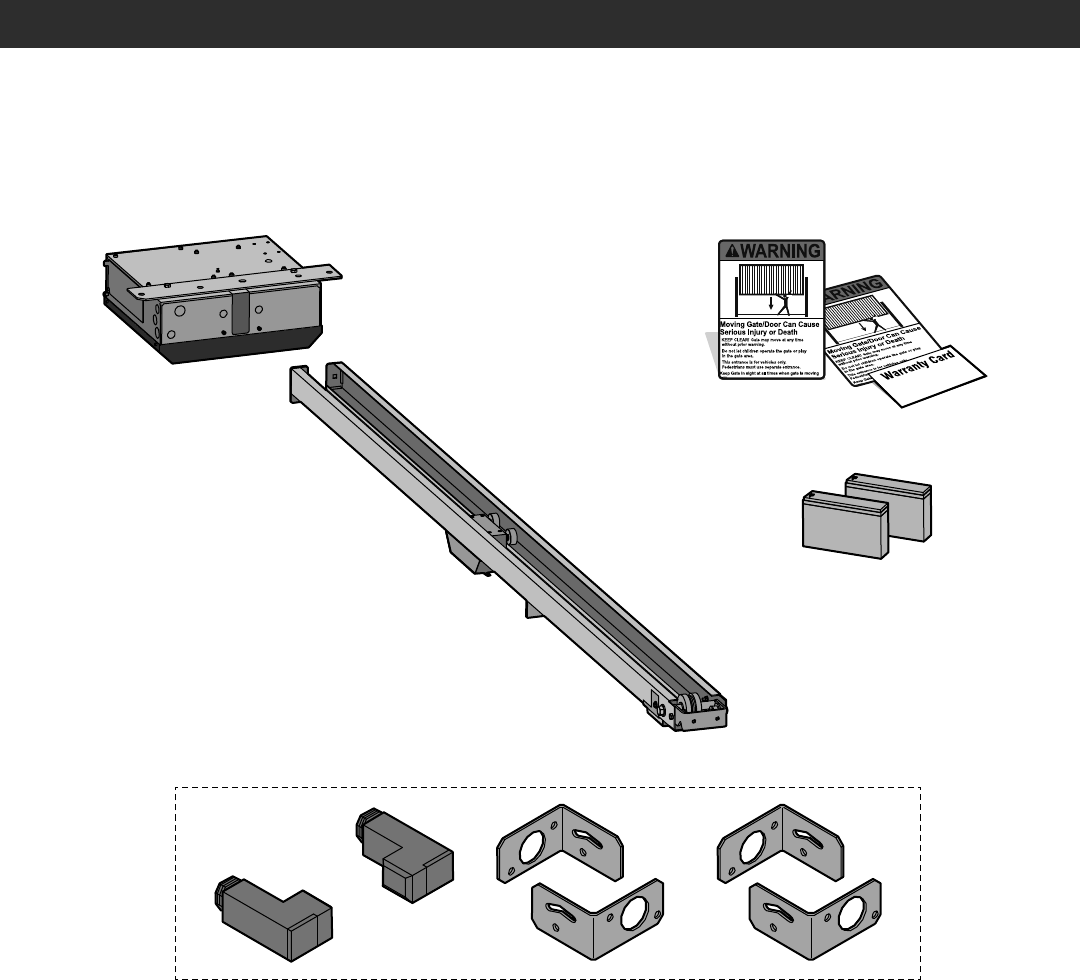
CARTON INVENTORY
NOT SHOWN: Documentation Packet
HCTDCU Motor Unit
8 Foot (2.4 m) Rail HCT08
10 Foot (3.1 m) Rail HCT10
12 Foot (3.7 m) Rail HCT12
Battery 12 Vdc 7AH (2)
Warning Signs (2) and Warranty Card
LiftMaster Photoelectric Sensors (CPSUN4G)
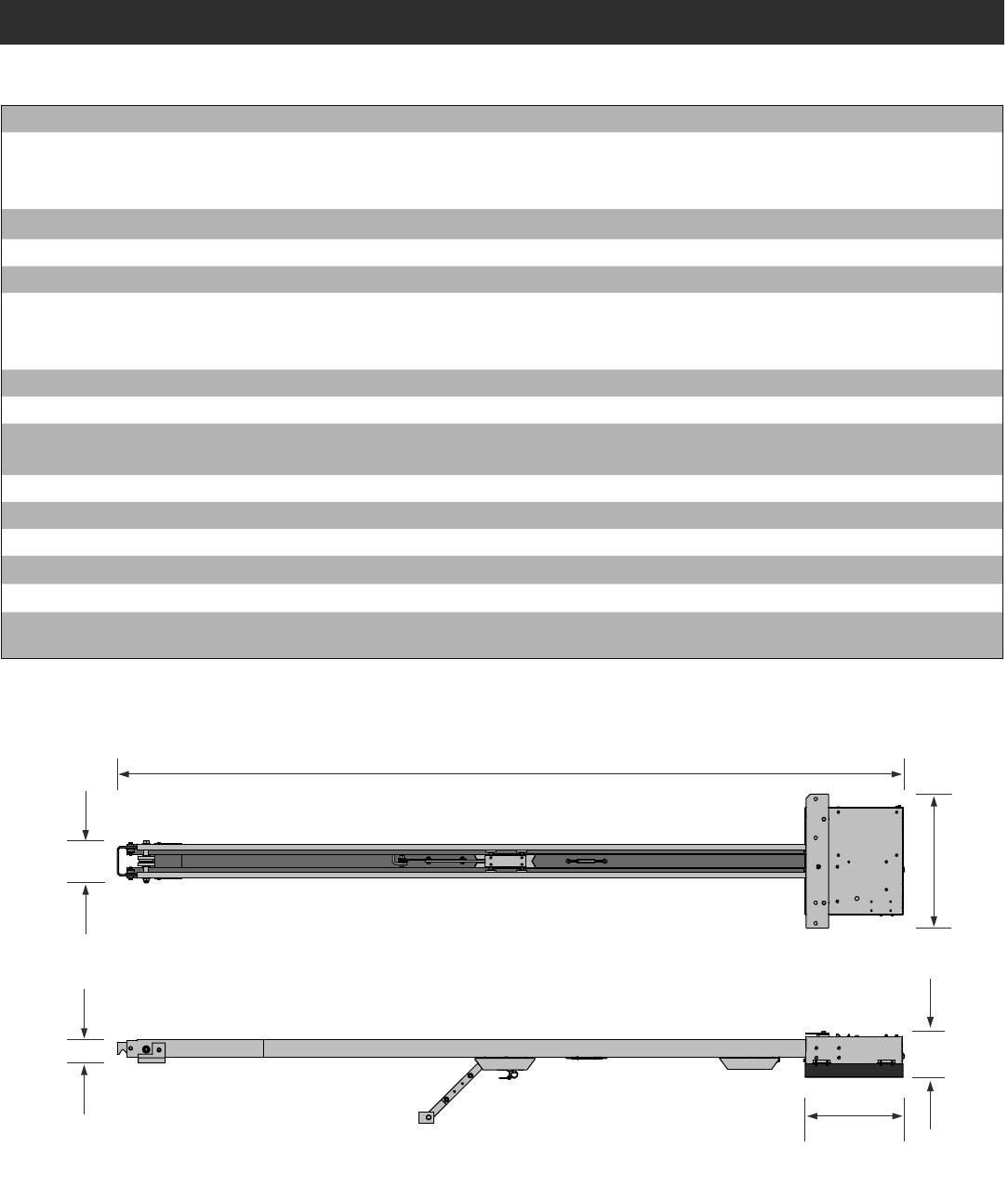
7
7.5"
(19.1 cm)
4.1"
(10.3 cm) 7.8"
(19.9 cm)
17.5"
(44.5 cm)
HCT08: 8' (2.4 m) rail
HCT10: 10' (3.1 m) rail
HCT12: 12' (3.7 m) rail
23.8"
(60.3 cm)
OPERATOR SPECIFICATIONS
INTRODUCTION
Usage Classification Class II, III, and IV
Main AC Supply 120 Vac, 4 Amps
OR
240 Vac, 2 Amps
System Operating Voltage 24 Vdc Transformer Run / Battery Backup
Accessory Power 24 Vdc, 500mA max. for ON + SW (switched)
Solar Power Max 24 Vdc at 60 watts max.
Variable Operating Lengths 8 foot (2.4 m) gate - 11.75 foot (3.6 m) operator length
10 foot (3.1 m) gate - 13.75 foot (4.2 m) operator length
12 foot (3.7 m) gate - 15.75 foot (4.8 m) operator length
Maximum Gate/Door Weight 700 lbs. (317.5 kg)
Maximum Gate/Door Width (sectional and one-piece) 22 ft. (6.7 m)
Travel Speed Default - 8 inches (20.3 cm) per second
Fast - 11 inches (27.9 cm) per second (open speed only)
Maximum Daily Cycle Rate Continuous
Maximum Duty Cycle Continuous
Operating Temperature -20°C to 60°C (-4°F to 140°F)
Expansion Board Provided
Inherent Entrapment Protection (Type A) Dual - RPM and Current Sense
External Entrapment Protection (Type B1 and/or Type B2) 3 inputs per board - any combination of up to 3 photoelectric sensors and up to 2
edge sensors
8
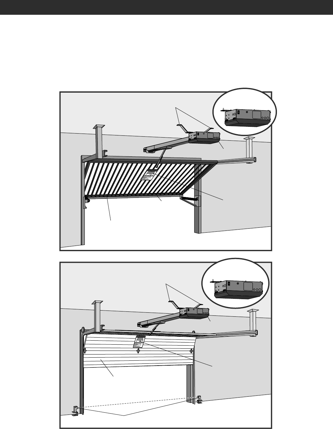
INTRODUCTION
OVERVIEW OF TYPICAL INSTALLATION
Operator
Warning Sign
Warning Sign
Photoelectric Sensors
Edge Sensor
Check the national and local building codes BEFORE installation.
NOTE: One or more contact or non-contact external monitored entrapment protection systems shall be located where the risk of entrapment or
obstruction exists at either the opening or closing direction. Care shall be exercised to reduce the risk of nuisance tripping, such as when a vehicle
trips the sensor while the gate/door is still moving.
Make sure the door opens and closes smoothly.
Door should stay in the open position when springs
are properly balanced.
Make sure the gate opens and closes smoothly.
Gate should stay in the open position when springs
are properly balanced.
Operator
Brackets (not provided) Flush Mount
Flush Mount
Brackets (not provided)
9
INSTALLATION
• ALWAYS wear protective gloves and eye protection when changing the battery or working around the battery compartment.
• NEVER wear watches, rings or loose clothing while installing or servicing operator. They could be caught in gate/door or operator mechanisms.
TO REDUCE THE RISK OF SEVERE INJURY OR DEATH:
IMPORTANT INSTALLATION INSTRUCTIONS
1. READ AND FOLLOW ALL INSTRUCTIONS.
2. Install operator ONLY on properly balanced and lubricated gate/
door. An improperly balanced gate/door may NOT reverse when
required and could result in SEVERE INJURY or DEATH.
3. ALL repairs to cables, spring assemblies and other hardware MUST
be made by a trained systems technician BEFORE installing
operator.
4. Disable ALL locks and remove ALL ropes connected to gate/door
BEFORE installing operator to avoid entanglement.
5. Install gate/door operator 8 feet (2.4 m) or more above floor.
6. NEVER connect operator to power source until instructed to do so.
7. Any openings shall be designed, guarded or screened to prevent a
2 1/4" (5.7 cm) diameter sphere from passing through the openings
anywhere in the gate/door.
8. Entrapment protection devices MUST be installed to protect anyone
who may come near a moving gate/door. Upon completion of
installation, test entrapment protection device.
9. Too much force on gate/door will interfere with proper operation of
safety reversal system.
• NEVER increase force beyond minimum amount required to move
gate/door.
• NEVER use force adjustments to compensate for a binding or
sticking gate/door.
• If one control (force or travel limits) is adjusted, the other control
may also need adjustment.
10. Install control station:
• within sight of the gate/door
• out of reach of children at minimum height of 5 feet (1.5 m)
• at least 6 feet (1.8 m) from the gate/door or ANY moving part of
the gate/door
11. This operator is intended for vehicular use ONLY. To prevent
INJURY to pedestrians, a separate pedestrian access should be
supplied, visible from the gate/door. Locate the pedestrian access
where there is NOT a chance of INJURY at ANY point during full
movement of the gate/door.
12. Install Warning signs on EACH side of gate/door in PLAIN VIEW.
Install one Warning Sign next to the control station. Permanently
secure each Warning sign in a suitable manner using fastening
holes.
13. SAVE THESE INSTRUCTIONS.
10
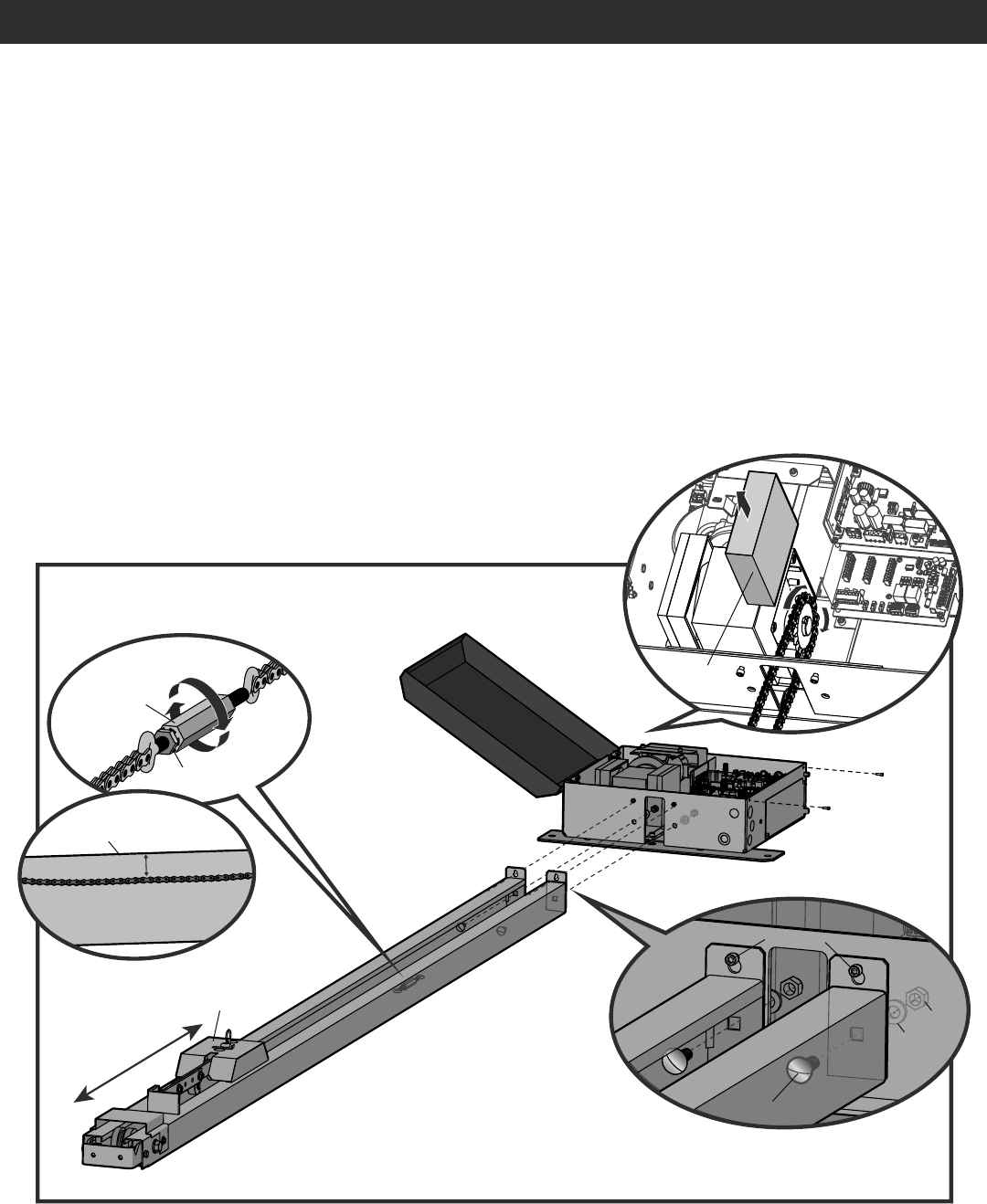
STEP 1
CONNECT RAIL TO OPERATOR
INSTALLATION
1. Remove the screws and open the cover of the operator.
2. Remove the chain guard from the chassis.
3. Lay the rail on the floor. Align the key holes on the end of the rail with the cap screws on the chassis.
4. Attach the rail to the chassis with the carriage bolts, lock nuts, and washers provided. Tighten cap screws on key holes.
5. Cut the cable tie on the chain and position the trolley within 3 feet (.9 m) of the end of the rail.
6. Wrap the chain around the sprocket.
7. Adjust the chain tension with the turnbuckle so that the chain hangs no more than 1/4" (.64 cm) from the top of the rail. Tighten the hex nut to
secure the chain.
8. Reattach the chain guard to the chassis.
9. Close the cover and attach with screws.
Within 3 feet (.9 m)
Top of Rail
Trolley
1/4" (.64 cm) Max.
Chain Guard
Hex Nut
Turnbuckle
Carriage Bolt
Cap Screw
Nut
Washer
1
2
3
4
5
6
7
11
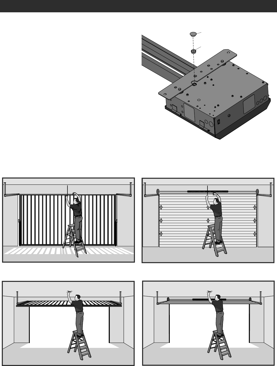
STEP 3
DETERMINE LOCATION FOR OPERATOR
INSTALLATION
1. With the gate/door closed, mark the center.
2. Open the gate/door and mark the center point on the ceiling.
STEP 2
INSTALL VENTED PLUG
1. Remove the dome plug from the operator chassis.
2. Remove the solid plug in the gear reducer and replace it with the
vented plug (provided in bag with manual).
3. Tighten the vented plug with a socket or Allen wrench.
4. Re-insert the dome plug.
Vented Plug
Dome Plug
12
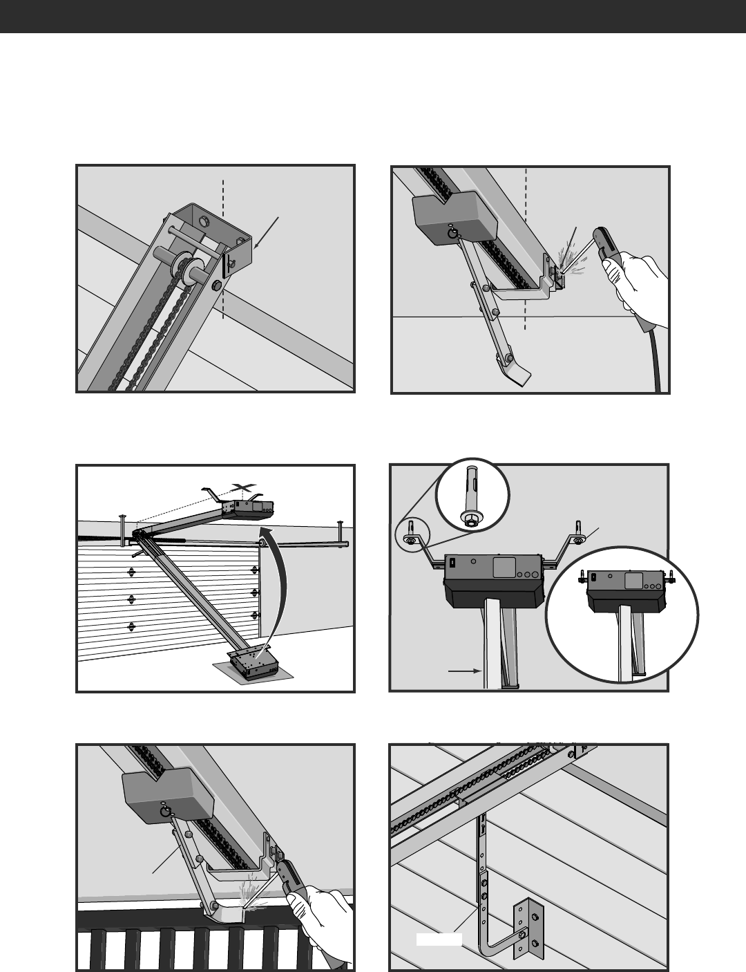
STEP 4
MOUNT THE OPERATOR
Header Bracket Header Bracket
Temporary
Support
Post
Concrete Anchor
1/2" x 3 1/2"
INSTALLATION
1. Place the motor unit on packing material to protect the cover. Make sure the header bracket is in the center of the opening. Bolt or weld the header
bracket to the wall.
2. Lift the operator and align with center mark on ceiling. Have someone hold the operator in place or use a post as a temporary support. Bolt
the operator to the ceiling. (A support post is not part of the operator. Use only for installation.)
3. Bolt or weld arm to gate/door.
Door Arm
Arm
Brackets
(not provided)
Flush
Mount