Fujitsu Technology Solutions SCENIC6651 personal computer User Manual A26361 K520 Z100 4 7619
Fujitsu Technology Solutions GmbH personal computer A26361 K520 Z100 4 7619
Contents
- 1. Manual Scenic 600 Oct 99 part 1
- 2. Manual Scenic 600 Oct 99 part 2
- 3. Manual Scenic 600 Oct 99 part 3
- 4. Manual Scenic 600 Oct 99 part 4
- 5. Manual Scenic 600 Oct 99 part 5
- 6. Manual Scenic 600 Oct 99 part 6
- 7. Manual Scenic 600 Oct 99 part 7
- 8. Scenic 600 Scenic xB May 2000 part1
- 9. Scenic 600 Scenic xB May 2000 part2
- 10. Scenic 600 Scenic xB May 2000 part3
- 11. Scenic 600 Scenic xB May 2000 part4
Manual Scenic 600 Oct 99 part 2
A26361-K520-Z100-4-7619 9
Preparation for use and operation
!Please take note of the safety information in the chapter "Important notes".
Unpacking and checking the delivery
It is recommended not to throw away the original packaging material! It may be required for
reshipment at some later date.
Unpack all the individual parts.
Check the delivery for damage incurred during transportation.
Check whether the delivery agrees with the details in the delivery note.
Should you discover that the delivery does not correspond to the delivery note, notify your local
sales outlet immediately.
iIf you have received drives or boards with your PC, please do not install them until after
first-time setup. How to install drives and boards is described in the chapter "System
expansions".
Preparing the PC for use
First-time setup includes the connection of the devices (monitor, mouse, keyboard etc.) and the
setup of the supplied software.
When you set up the PC for the first time, you should carry out the following steps in the order
shown:
1. Decide where you are going to use the PC.
2. Connect the external devices to the system unit.
3. Check the rated voltage of the system unit and connect it to the line voltage.
4. Switch the PC on and follow the instructions on the screen.

Preparation for use and operation Setting up the PC
10 A26361-K520-Z100-4-7619
Setting up the PC
!When installing your PC, give consideration to the recommendations and safety notes in
the manual "Safety, Guarantee and Ergonomics".
Set up the PC only in its correct orientation. The points to observe are illustrated on the
following pages.
We recommend that you place your equipment on a surface with good anti-slip qualities.
In view of the multitude of different finishes and varnishes used on furniture, it is possible
that the rubber feet of the devices will mark the surface they stand on.
Do not expose the PC to extreme environmental conditions (see chapter "Technical
data"). Protect it from dust, humidity and heat.
Provide at least 200 mm of clearance on the left, in front of and behind the ventilator area
of the system unit to ensure adequate ventilation. Do not cover the ventilation areas of the
monitor and the system unit.
Do not place any objects that weigh more than 40 kg on the system unit and not several
system units one above the other.
Connecting devices
!The power plug must be disconnected!
Read the documentation on the external device before connecting it.
Do not connect or disconnect cables during a thunderstorm.
Always take hold of the actual plug body. Never unplug a cable by pulling the cable itself.
Connect and disconnect the cables in the order described below.
Connecting cables
• Turn off all power and equipment switches.
• Unplug all power plugs from the grounded power outlets.
• Connect all cables at the system unit and peripherals. You must observe the information
provided in the chapter "Important notes".
• Plug all data communication cables into the utility sockets.
• Plug all power cables into the grounded power outlets.
Disconnecting cables
• Turn off all power and equipment switches.
• Unplug all power plugs from the grounded power outlets.
• Unplug all data communication cables from the utility sockets.
• Disconnect all cables from the system unit and peripherals.
Connecting devices Preparation for use and operation
A26361-K520-Z100-4-7619 11
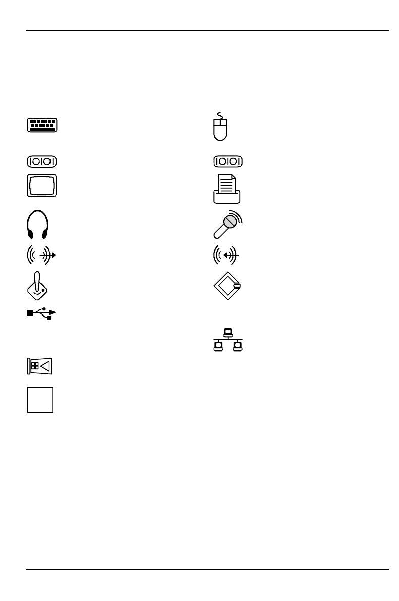
Ports for external devices
The ports for external devices are on the rear and on the front of the system unit. The ports
available on your device depend on the configuration level you have selected. The standard ports
are marked with symbols like those below or similar symbols. Exact details of the position of the
ports are supplied in the Technical Manuals for the boards.
Keyboard port PS/2 mouse port
1Serial port 1 2Serial port 2
Video connector Parallel interface / Printer
Earphone Microphone jack
Audio output (Line out) Audio input (Line in)
Game port SCSI connection
USB - Universal Serial Bus
LAN
LAN port
Chipcard reader
iSome of the devices that you connect require special drivers (see the documentation for
the connected device and for the operating system).
Preparation for use and operation Connecting devices
12 A26361-K520-Z100-4-7619
Connecting the keyboard
iUse only the keyboard cable supplied.
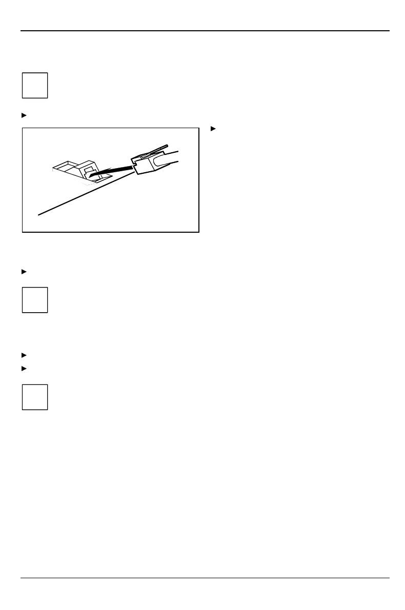
Plug the round plug of the keyboard cable into the keyboard port on the system unit.
Plug the other connector of the keyboard
cable into the socket on the underside of
the keyboard.
Connecting the mouse
Plug the connector of the mouse cable into the mouse port.
iIf you do not attach a mouse at the PS/2 mouse port, you can disable the mouse
controller in the BIOS-Setup in order to free the IRQ12 for a different application.
Connecting devices with serial or parallel port
Connect the data cable to the external device.
Connect the data cable of the external device to the appropriate port on the system unit.
iMost devices that you connect to the serial or parallel port require special drivers. Your
operating system already includes many drivers . But if the driver you need is not on the
hard disk please install it from the floppy disk supplied with the device or with the
application program.
If you need to change the default settings of the serial or parallel port (e.g. address,
interrupt), you can do so in the BIOS Setup. The default setting for the interfaces are
described in the Technical Manual for the system board or in the "BIOS Setup" manual.
Connecting devices Preparation for use and operation
A26361-K520-Z100-4-7619 13
Connecting the monitor to the line voltage
Prepare the monitor as described in the Operating Manual for the monitor.
Plug the data cable of the monitor into the monitor port of the system unit.
1
2
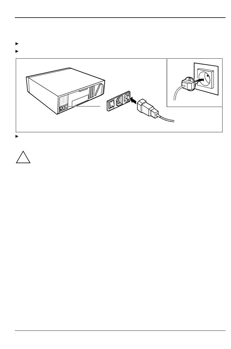
Depending on the connector, plug the monitor power cable into either the system unit (1) or the
grounded power outlet (2).
!You may only plug the monitor power cable into the monitor connector if the rated current
of the monitor is less than 1.5 A (230 V) or 3 A (115 V). The rated current for the monitor
is also given on the monitor itself and in the Operating Manual for the monitor.
Preparation for use and operation Connecting the PC to the line voltage
14 A26361-K520-Z100-4-7619
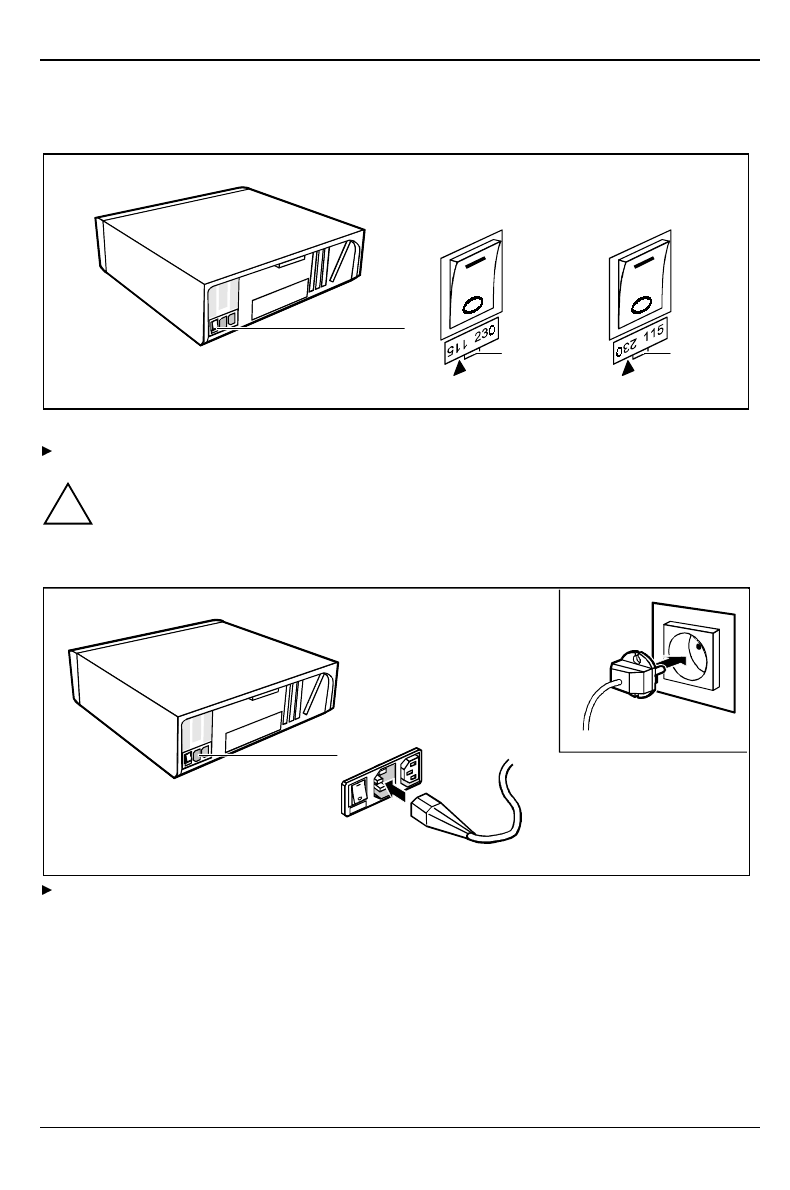
Connecting the PC to the line voltage
100 V - 125 V 200 V - 240 V
1 1
1 = Notch for inserting the screwdriver
Check the rated voltage.
!The value marked with an arrow must agree with the local line voltage:
115 = 100 V to 125 V 230 = 200 V to 240 V
If the rated voltage does not agree with the local line voltage, lift out the plug-in unit with a
screwdriver (1), turn it and replace it.
2
1
Plug the system unit's power cable into the system unit (1) and then into the grounded power
outlet (2).
Unlocking/locking the system unit Preparation for use and operation
A26361-K520-Z100-4-7619 15
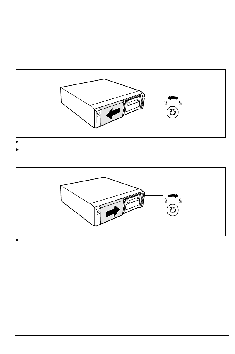
Unlocking/locking the system unit
With the casing lock you can mechanically lock the system unit, and with the drive cover you can
block access to the drives.
Unlocking the system unit
1
2
Turn the key counterclockwise (1).
Slide the drive cover in direction of the arrow (2).
Locking the system unit
2
1
Slide the drive cover in direction of the arrow (1) and turn the key clockwise (2).
Preparation for use and operation Switching the PC on and off
16 A26361-K520-Z100-4-7619
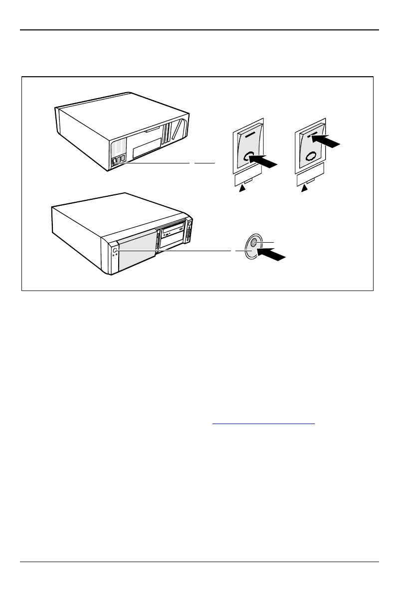
Switching the PC on and off
1
23
0I
1 = Main switch
2 = ON/OFF switch
3 = Power-on indicator
0 = System unit is switched off
I = System unit is ready-to-operate
System unit is off
The main switch (1) is in position 0, the power-on indicator (3) does not light, and the ON/OFF
switch (2) is disabled.
System unit is ready-to-operate
The main switch (1) is in position I and the power-on indicator (3) lights up orange or flashes
green/orange. In this mode, you can switch the system unit on with the ON/OFF switch (2). The
"ready-to-operate" status corresponds to the "stand-by" status of a TV set. The exact description of
the power-on indicator (3) is contained in the section "Indicators on the system unit".
System unit is on
The main switch (1) is in position I and the power-on indicator (3) lights up green. The system unit
can be switched ready-to-operate with the ON/OFF switch (2).