Fujitsu Technology Solutions SCENIC6651 Personal Computer User Manual A26361 K520 Z200 1 7619
Fujitsu Technology Solutions GmbH Personal Computer A26361 K520 Z200 1 7619
Contents
- 1. Manual Scenic 600 Oct 99 part 1
- 2. Manual Scenic 600 Oct 99 part 2
- 3. Manual Scenic 600 Oct 99 part 3
- 4. Manual Scenic 600 Oct 99 part 4
- 5. Manual Scenic 600 Oct 99 part 5
- 6. Manual Scenic 600 Oct 99 part 6
- 7. Manual Scenic 600 Oct 99 part 7
- 8. Scenic 600 Scenic xB May 2000 part1
- 9. Scenic 600 Scenic xB May 2000 part2
- 10. Scenic 600 Scenic xB May 2000 part3
- 11. Scenic 600 Scenic xB May 2000 part4
Scenic 600 Scenic xB May 2000 part4
System expansions
34 A26361-K520-Z200-1-7619
1
a
3
2
Ê Push the board up to its slot (1).
Ensure that the end of a long board without angle bracket fits into the corresponding guide of
the system unit. Ensure also that the point of the angle bracket slots into guide (a).
Ê Press the board into the slot so that it engages.
Ê Replace the clip (2) which fixes the board. Make sure that the clip engages when released (3).
Ê If necessary, plug the lines on the board.
Ê Close the system unit (see "Assembling the system unit").
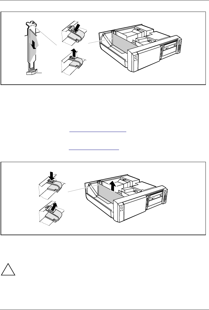
Removing a board
Ê Open the system unit (see "Opening the system unit").
Ê Remove the lines connected to the board.
3
1
2
Ê Press on the clip in the direction of the arrow (1) and remove it (2).
Ê Remove the board from the system unit (3).
Ê Place the board into an appropriate packaging.
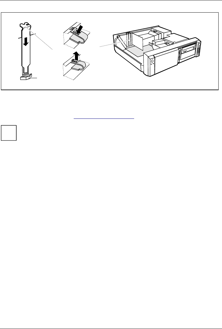
!For cooling, protection against fire and in order to comply with EMC (electromagnetic
compatibility) regulations, you must refit the rear slot cover plate.
System expansions
A26361-K520-Z200-1-7619 35
13
2
a
Ê Push the rear slot cover plate into the slot (1). Ensure that the point of the cover engages into
the guide (a).
Ê Replace the clip (2) which fixes the board. Make sure that the clip engages when released (3).
Ê Close the system unit (see "Assembling the system unit").
i
If you have installed or removed a PCI board, please check in the BIOS Setup the settings
for the relevant PCI slot. If necessary, change the settings. Further information is provided
in the documentation for the PCI board.
Installing and removing drives
The system unit houses a total of three accessible drives (two 5 1/4-inch drives and one 3 1/2-inch
drive) and two non-accessible half-height (Slimline) drives .
IDE drives
By default four IDE drives are supported. Ideally hard disks are connected to IDE port 1, and
accessible IDE drives, for example CD-ROMs, to IDE port 2 (see also the Technical Manual for the
system board).
SCSI drives
If you want to install an SCSI drive, you require an SCSI controller and an SCSI cable. Note that:
• not every SCSI controller is suitable for operating SCSI hard disks
• each SCSI device must be assigned its own SCSI-ID.
• the SCSI cable must always be terminated at the end, either by a drive or by a terminating
resistor on the cable. The terminating resistors of all other SCSI devices attached must not be
activated or connected.
• depending on the SCSI technology (UW, U2W), an adapter may be required for connecting the
SCSI drives with a 50-pin connector.
System expansions
36 A26361-K520-Z200-1-7619
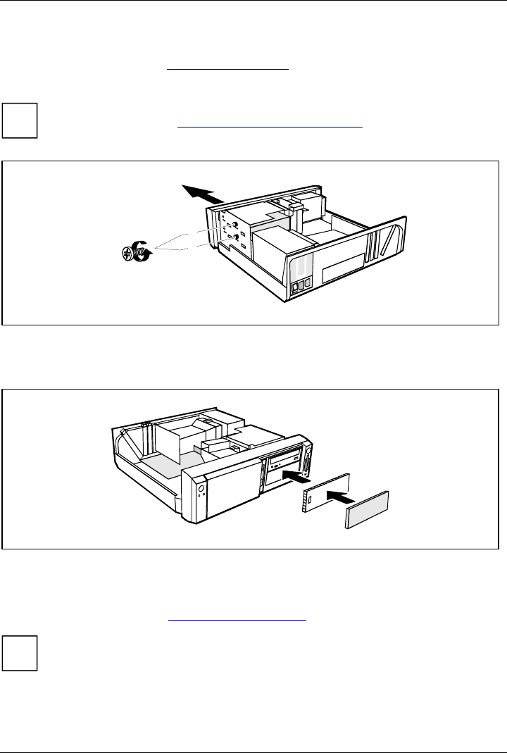
Installing an accessible drive
Ê Open the system unit (see "Opening the system unit").
i
Should the chipcard reader get in the way of the accessible drive during installation, then
remove the reader (see "Installing/removing a chipcard reade
r
").
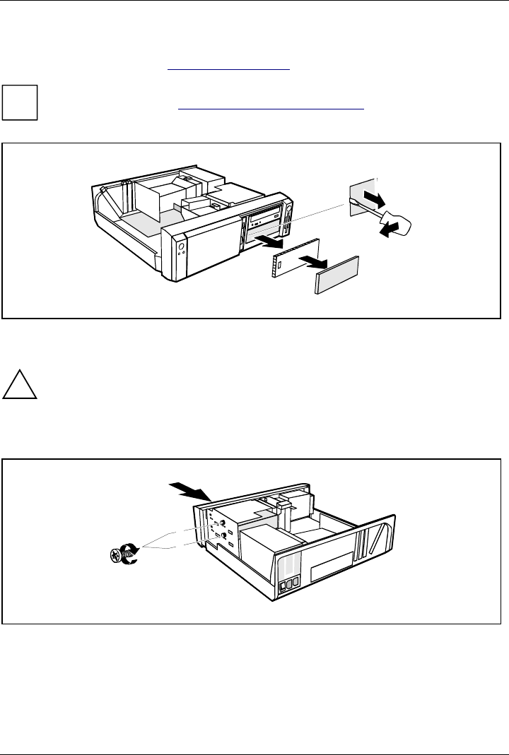
A
B
1
2
Ê Pry the plastic drive cover (A) out of the front cover.
Ê Pry the shielding plate (B) on left-hand side out of the bay.
!Do not throw away the covers. If you remove the drive again later, you will have to
reinstall the covers.
Ê Take the new drive out of its packaging.
Ê Make the required settings on the drive (if necessary, on installed drives as well).
2
1
A
B
A = Position of the screw for the upper drive
B = Position of the screw for the lower drive
Ê Slide the drive into the system unit (1).
Ê Plug the data and the power supply connectors into the drive.
Ê Fasten the drive with the screw (2).
Ê If you have removed the chipcard reader, then reinstall it.
System expansions
A26361-K520-Z200-1-7619 37
Ê Close the system unit (see "Assembling the system unit").
i
If necessary, you must adapt the entry for the drive in the Setup menu.
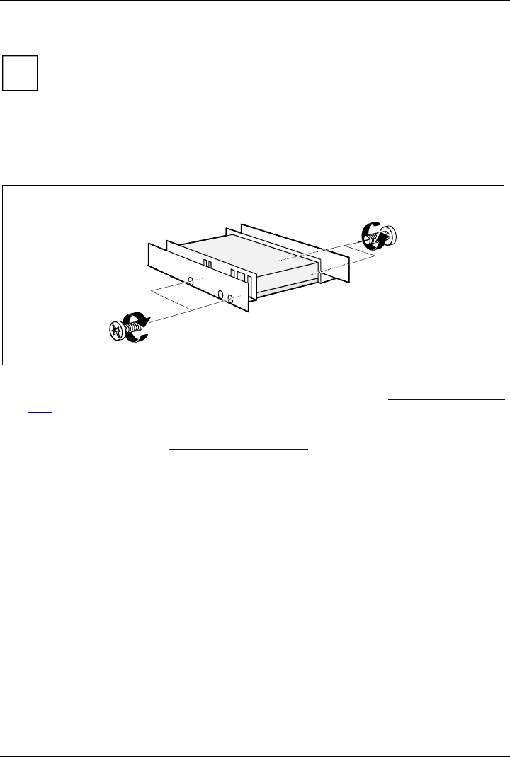
Installing a hard disk drive in the front bay
Ê Open the system unit (see "Opening the system unit").
Ê Make the required settings (e. g. master-slave) on the hard disk drives.
Ê Fasten the drive with the four screws (2).
Ê Install the installation frame with the drive in the desired front bay (see "Installing an accessible
drive").
Ê Close the slot with the panel. Ensure that the cover engages.
Ê Close the system unit (see "Assembling the system unit").
System expansions
38 A26361-K520-Z200-1-7619
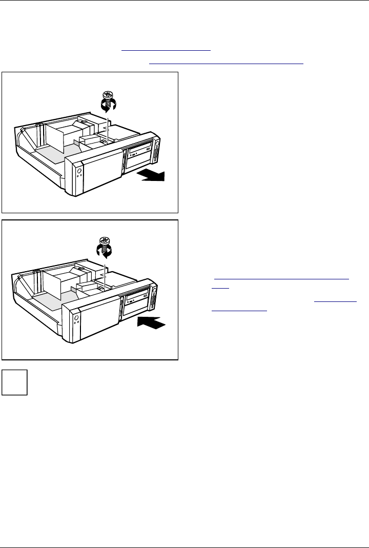
Removing an accessible drive
Ê Open the system unit (see "Opening the system unit").
Ê Pull the data and the power supply connectors from the desired drive.
i
Should the chipcard reader get in the way of the accessible drive during installation, then
remove the reader (see "Installing/removing a chipcard reade
r
").
1
2
A
B
A = Position of the screw for the upper drive
B = Position of the screw for the lower drive
Ê Remove the relevant screw (1) and take the drive out of the system unit (2).
A
B
Ê Insert the shielding plate (B) on the right-hand side on the installation bay and press it in.
Ê Press the plastic drive cover (A) into the front panel until it snaps in place.
Ê If you have removed the chipcard reader, then reinstall it.
Ê Close the system unit (see "Assembling the system unit").
i
If necessary, you must adapt the entry for the drive in the Setup menu.
System expansions
A26361-K520-Z200-1-7619 39
Changing the floppy disk drive
Ê Open the system unit (see "Opening the system unit").
Ê Remove the hard disk carrier (see "Installing and removing the hard disk drive").
1
2
Ê Pull the data and the power supply
connectors from the floppy disk drive.
Ê Remove the screw (1) and take the drive
out of the system unit (2).
Ê Take the new floppy disk drive out of its
packaging.
2
1
Ê Push the drive into the system unit (1), and
fix it with the screw (2).
Ê Plug the data and the power supply
connectors into the floppy disk drive.
Ê Remove the hard disk carrier (see
"Installing and removing the hard disk
drive").
Ê Close the system unit (see "Assembling
the system unit").
i
If necessary, you must adapt the entry for the drive in the Setup menu.
System expansions
40 A26361-K520-Z200-1-7619
Installing and removing the hard disk drive
Ê Open the system unit (see "Opening the system unit").
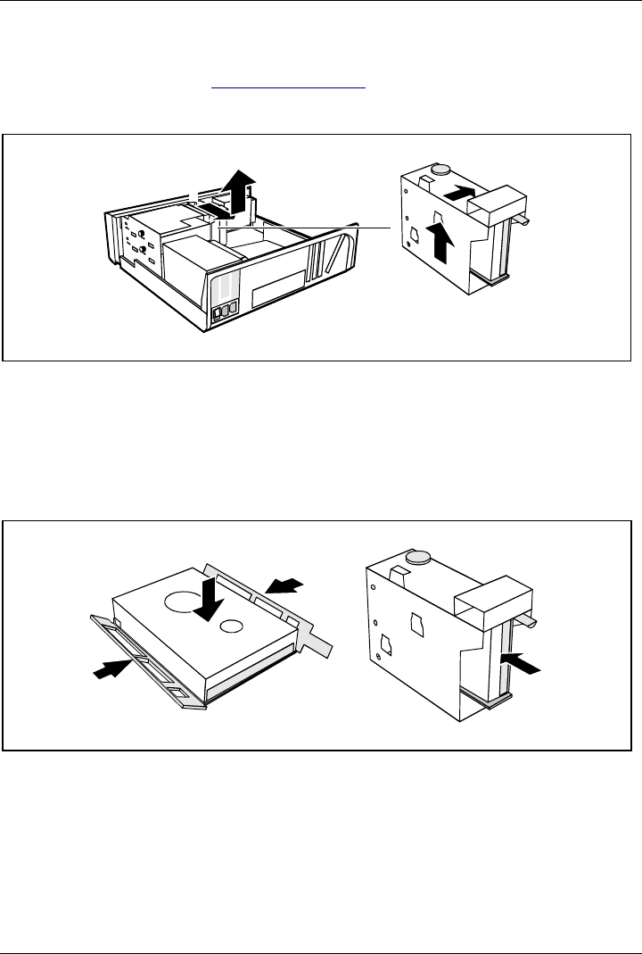
Removing the hard disk carrier
2
1
34
Ê Lift the hard disk carrier out of the mounting in the direction of the arrow (1) and (2).
Ê Lift the hard disk carrier out of the system unit in the direction of the arrow (3) and (4).
Ê Pull the data and power supply connectors from the hard disk drive or the hard disk drives.
Installing the first hard disk drive
Ê Take the new hard disk drive out of its packaging.
Ê Make the required settings (e. g. master/slave, stand alone) on the drives.
2
2
1
3
Ê Insert the hard disk drive into the plastic bracket (1). The drive must engage in the plastic
nipple.
Ê Fold the plastic bracket in the direction of the arrow (2) on the hard disk drive.
Ê Push the hard disk drive into the drive carrier until the plastic bracket engages (3).
System expansions
A26361-K520-Z200-1-7619 41
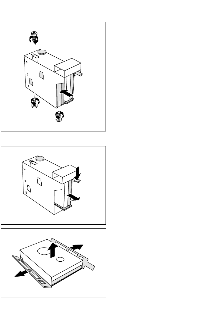
Installing the second hard disk drive
2
2
2
1
Ê Take the new hard disk drive out of its
packaging.
Ê Make the required settings (e. g.
master/slave, stand alone) on the drives.
Ê Slide the hard disk drive into the drive
carrier (1).
Ê Fasten the drive with the screws (2).
Removing the first hard disk drive
1
2
Ê Lightly press on the clip (1).
Ê Pull the hard disk drive out of the carrier
(2).
1
1
2
Ê Fold the plastic bracket in the direction of
the arrow (1).
Ê Remove the hard disk drive (2).
System expansions
42 A26361-K520-Z200-1-7619
Removing the second hard disk drive
2
1
1
1
Ê Remove the screw (1).
Ê Pull the hard disk drive out of the carrier
(2).
Ê Make the required settings on the
remaining hard disk drive (e.g. stand
alone).
Installing the hard disk carrier
3
4
21
Ê Plug the data and the power supply connectors into the hard disk drive or into the hard disk
drives.
Ê Lift the hard disk carrier into the system unit in the direction shown by the arrow (1) and push it
forward until it engages (2).
Ê Press the hard disk carrier in the direction of the arrow (3) and press it downward (4).
Ê Close the system unit (see "Assembling the system unit").
i
If necessary, you must adapt the entry for the drive in the Setup menu.
System expansions
A26361-K520-Z200-1-7619 43
Installing/removing a chipcard reader
Ê Open the system unit (see "Opening the system unit").
Installing a chipcard reader
Ê Remove the protector panel at the front of the carrier.
Ê Push the chipcard reader board into the guide rail of the carrier with the component's side
toward the panel.
Ê Fix the board with the screw.
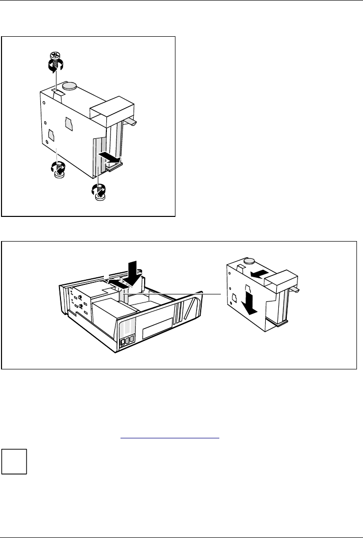
3
1
2
Ê Fix the cable on the chipcard reader (1) and on the connector for the chipcard reader on the
system board (see the Technical Manual of the system board).
Ê Lift the chipcard reader into the system unit (2).
Ê Push the chipcard reader in the direction of the arrow (3) until it clicks into position. Press
downward and toward the drive cage while doing so.
i
With the chipcard reader connected, no devices may be connected to serial port 2.
Removing a chipcard reader
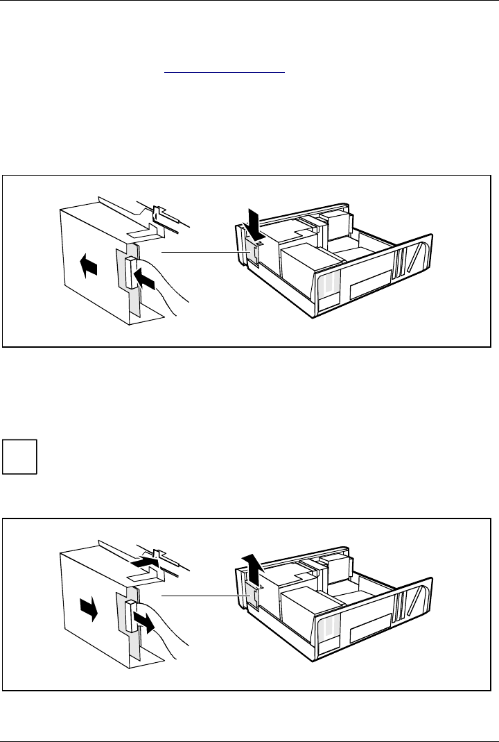
2
3
1
4
Ê Pull the cable off the chipcard reader (1) and off the connector for the chipcard reader on the
system board (see the Technical Manual of the system board).
System expansions
44 A26361-K520-Z200-1-7619
Ê Press on the clip (2).
Ê Pull the chipcard reader in the direction of the arrow (3).
Ê Lift the chipcard reader out of the system unit (4).
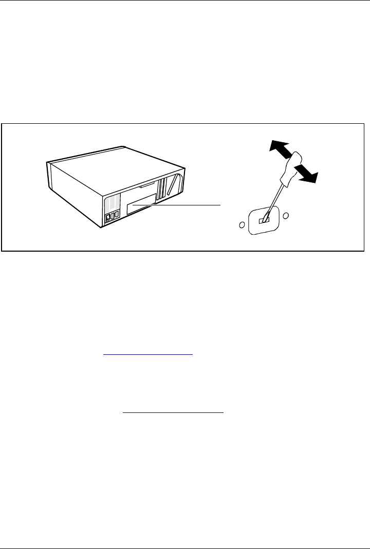
Installation opening for 2nd serial port
An installation opening for the 2nd serial port is provided on the back of the casing. As a result, this
means no board slot is occupied.
Ê Insert a screwdriver into the opening and break out the pre-stamped installation opening by
moving back and forth.
Extensions on the system board
Details of how and if you can upgrade the main memory or the processor of your PC are provided in
the Technical Manual for the system board. Below the necessary steps are described to enable you
to work on the system board.
Open the system unit (see "Opening the system unit").
Upgrading main memory
Ê Upgrade the memory as it is described in the Technical Manual for the system board.
Ê Close the system unit (see "Assembling the system unit").
System expansions
A26361-K520-Z200-1-7619 45
Replacing processor and lithium battery
To replace the processor and the lithium battery, you must remove the ventilation duct.
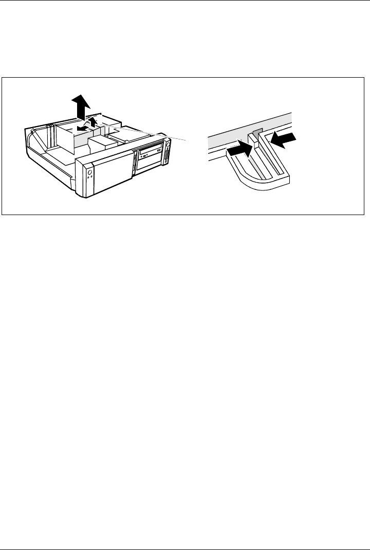
Removing ventilation duct
2
3
4
11
Ê Press the clip together (1).
Ê Lift the ventilation duct slightly (2) and guide the ventilation duct out of the guide holes (3).
Ê Remove the ventilation duct from the unit (4).
You have free access to the locations.
Replacing processor
Ê Make the desired expansions (see the Technical Manual for the system board).
System expansions
46 A26361-K520-Z200-1-7619
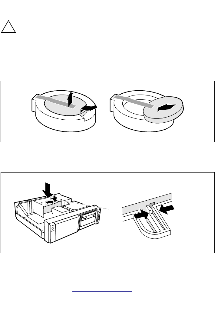
Replacing lithium battery
!Incorrect replacement of the lithium battery may lead to a risk of explosion.
The lithium battery may be replaced only with an identical battery or with a type
recommended by the manufacturer.
Do not throw lithium batteries into the trashcan. It must be disposed of in accordance with
local regulations concerning special waste.
Make sure that you insert the battery the right way round. The plus pole must be on the
top!
1
23
+
++
+
Ê Lift the contact (1) a few millimeters and remove the battery from its socket (2).
Ê Insert a new lithium battery of the same type in the socket (3).
Installing ventilation duct
4
3
1
22
Ê Lift the ventilation duct into the unit (1).
Ê Press the clip together (2).
Ê Insert the ventilation duct into the guide holes (3) in the power supply.
Ê Push the ventilation duct downward until the clip engages (4).
Ê Close the system unit (see "Assembling the system unit").

A26361-K520-Z200-1-7619 47
Technical data
Electrical data
Regulations complied with: EN 60950 / VDE 0805
UL 1950
CSA 22.2 No.950
Protection class: I
Rated voltage range: (selectable) 100V-125V/200V-240V
Frequency: 50 Hz - 60 Hz
Max. rated current
• System unit with monitor socket:
• Monitor socket (output)
100 V -125 V/5.5 A
200 V -240 V/3.0 A
100 V -125 V/3 A
200 V -240 V/1.5 A
Maximum power draw in operation:
Minimum power draw in operation:
reduced by Windows 9x
Power management advanced_
Power draw in energy saving mode:
Power draw in the 'ready' status
<60W *)
<35W *)
<30W *)
<5W *)
Noise emission: Sound power level (
L
WAd
)<55dB(A)*)
*) These values only apply for a SCENIC 600 / SCENIC xB with the configuration below. When
additional or other components are incorporated, the power consumption or the sound
emission (LWAd) in energy saving mode may exceed the requirements for the environment
symbol ("Blue Angel") (30 W or 55 dB).
Processor (512 Kbyte cache):
Main memory:
Floppy disk drive:
Hard disk drive:
CD-ROM drive:
Graphics:
LAN:
Pentium III Processor at 600 MHz
192 Mbyte
1.44 Mbyte
6.4 Gbyte
32fold
Matrox MGA G100 AGP
10/100 Mbit Ethernet Controller onboard
Dimensions
Width/depth/height: 454 mm/475 mm/ 138 mm
Weight
in basic configuration ca. 11 kg (107.9 N) in basic configuration

Technical data
48 A26361-K520-Z200-1-7619
Environmental conditions
Environment class (3K2)
Environment class (2K2) DIN IEC 721 part 3-3
DIN IEC 721 part 3-2
Temperature:
• Operating (3K2)
• Transport (2K2) 15 °C .... 35 °C
-25 °C .... 60 °C
Condensation in operating must be avoided.
Clearance required to ensure adequate ventilation:
• left-hand side
• front
• rea
r
min. 200 mm
min. 200 mm
min. 200 mm
!Do not place several system units one above the other.

A26361-K520-Z200-1-7619 49
Index
2
2nd serial port, installation opening 44
A
Accessible drive
installing 36
removing 38
Accumulator, disposal 5
Activating, security measures 23
Alphanumeric keypad 20
Alt Gr key 21
Anti-theft protection 24
Audio input 11
Audio output 11
B
Battery 46
disposal 5
BIOS Setup 23
security functions 24
Board 3
installing 33
removing 33
C
Cable
connecting 10
disconnecting 10
Cabling, PC 10
Calculator keypad 20
Casing
lock 15
opening 31
CD-ROM drive
indicator 19
installing 36
manual 29
removing 38
CE certificate 5
Changing
floppy disk drive 39
hard disk drive 40
lithium battery 46
Checking, rated voltage 14
Chipcard reader 11
indicator 20
Class B Compliance Statement 5
Cleaning 8

Index
50 A26361-K520-Z200-1-7619
Clearance 48
Configuration, BIOS-Setup 23
Connecting
cables 10
devices 10
keyboard 12
monitor 13
mouse 12
parallel port 12
power voltage 14
serial port 12
Connecting to power voltage 14
Contents of delivery 9
Control key 21
Courier 1
Ctrl key 21
Ctrl+Alt+Del 21
Cursor control keys 20
D
Dark screen 26
Dataprotection 23
technical 47
Date, not correct 28
Devices
connecting 10
interface 11
Dimensions 47
Diskette 22
write-protection 22
Display, cleaning 8
Disposal 4
Drive 35
cover 15
hard disk drive, installing 37
E
Earphone 11
Electrical data 47
Electromagnetic compatibility 5
Energy saving 4
Enter key 21
Environmental conditions 48
Environmental data 48
Ergonomic, video workstation 10
Errordate 28
floppy 27
mouse 27
screen 26
system unit 25
time 28
Error message 28

Index
A26361-K520-Z200-1-7619 51
ESD 3
Euro key 21
Expansion 31
External devices
connecting 10
ports 11
F
FCC statement 5
First time, switching on 17
Flashing power-on indicator 19
Floppy disk drive
changing 39
indicator 20
removing 38
Floppy disk, cannot be read or written 27
Function keys 20
G
Game port 11
Green, power-on indicator 19
Guarantee coupon booklet 9
H
Hard disk carrier
installing 42
removing 40
Hard disk drive
installing 37
replacing 40
Hard disk indicator 19
I
IDE drives 35
Important notes 3
Indicator
power-on indicator fails to light 25
remains blank 26
Indicators, on the PC 19
Installation opening, 2nd serial port 44
Installing
accessible drive 36
board 33
hard disk carrier 42
hard disk drive 40,41
new Software 25
ventilation duct 46
Insufficient memory 28
Interfaces 11
Italics 1
K
Kensington Lock 24

Index
52 A26361-K520-Z200-1-7619
Key combination 21
Keyboard 20
cleaning 8
connecting 12
port 11
Keys 21
L
LAN port 11
Lead-sealing 24
Line in 11
Line out 11
Lithium battery 44
replacing 46
Lock 15
Locking, PC 15
M
Main memory 44
Main switch 16
Manuals, further 29
Manufacturer’s notes 4
Memory, upgrading 44
Menu key 21
Message indicator 19
Microphone jack 11
Monitor
connecting 13
port 11
transporting 7
Mouse
cleaning 8
connecting 12
error 27
port 11
N
New Installation, Software 25
No screen display 26
Noise level 47
Not enough memory 28
Notational conventions 1
Noteboards 3
CE certificate 5
disposal 4
energy saving 4
important 3
manufacturer 4
power cord selection 6
safety 3
Num Lock key 21
Numeric keypad 20

Index
A26361-K520-Z200-1-7619 53
O
ON/OFF switch 16,21
Opening, system unit 31
Operation 9
Orange, power-on indicator 19
Other manuals 29
Overview
PC 1
preparing for use 9
P
Packing material 9
Parallel port 11
connecting devices 12
PC cabling 10
cannot boot 25
cleaning 8
connecting 10
connecting to power voltage 14
indicators 19
locking 15
opening 31
ports 11
setting up 10
switching off 16,18
switching on 16,18
switching on for the first time 17
transporting 7
unlocking 15
Ports, external devices 11
Power cord selection 6
Power management 28
Power-on indicator 16,19
dark 25
POWERSAV.SCR 4
Preparation for use 9
Preparing for use, overview 9
Printer 11
Problems 25
Processor 44
replacing 45
Property protection 23
PS/2 mouse port 11
Q
Quiet Boot 26
R
Rated voltage, setting 14
Ready-to-operate 16
Recycling 4
Reinstalling, hard disk contents 28
Removing

Index
54 A26361-K520-Z200-1-7619
accessible drive 38
board 33
hard disk carrier 40
hard disk drive 41,42
ventilation duct 45
Replacing
board 33
hard disk drive 40
lithium battery 46
Restoring, hard disk contents 28
Return key 21
S
Safety 3
Screen blank 17,18,26
Screen blanking 4
SCSI drives 35
SCSI port 11
Security function 24
casing lock 23
chipcard 23
MS-Windows 23
Security measures 23
Select, power cord 6
Serial port 11
connecting devices 12
Setting rated voltage 14
Settings, BIOS Setup 23
Setup, see BIOS Setup
Shift key 21
Soft Power Off 18
Software, New Installation 25
Start key 21
Streamer
installing 36
removing 38
Summer time 28
Surface 47
Switching off, PC 16,18
Switching on, PC 16,18
Symbols, explanation of 1
System board, extensions 44
System expansion 31
System settings, BIOS Setup 23
System unit, see PC
T
Technical data 47
Time, not correct 28
Tips 25,28
Transport 7
Trouble
floppy disk 27
mouse 27

Index
A26361-K520-Z200-1-7619 55
screen 26
system unit 25
Troubleshooting 25
U
Unlocking, PC 15
Unpacking 9
Upgrading, memory 44
USB, Universal Serial Bus 11
V
Ventilation area 48
Ventilation duct
installing 46
removing 45
VESA (DPMS) 4
Video workstation 10
W
Warm boot 21
Weight 47
Winter time 28
Write protection, floppy 22