Fujitsu Technology Solutions SCENIC6651 personal computer User Manual A26361 K520 Z100 4 7619
Fujitsu Technology Solutions GmbH personal computer A26361 K520 Z100 4 7619
Contents
- 1. Manual Scenic 600 Oct 99 part 1
- 2. Manual Scenic 600 Oct 99 part 2
- 3. Manual Scenic 600 Oct 99 part 3
- 4. Manual Scenic 600 Oct 99 part 4
- 5. Manual Scenic 600 Oct 99 part 5
- 6. Manual Scenic 600 Oct 99 part 6
- 7. Manual Scenic 600 Oct 99 part 7
- 8. Scenic 600 Scenic xB May 2000 part1
- 9. Scenic 600 Scenic xB May 2000 part2
- 10. Scenic 600 Scenic xB May 2000 part3
- 11. Scenic 600 Scenic xB May 2000 part4
Manual Scenic 600 Oct 99 part 3
Switching the PC on and off Preparation for use and operation
A26361-K520-Z100-4-7619 17
Switching on the PC for the first time
When you switch on your PC for the first time the supplied software is set up and configured.
iIf the PC is integrated into a network, the user and server details as well as the network
protocol are required. Contact your network administrator if you have any questions about
these details.
The license number for Windows is printed on the front cover of the Windows manual
supplied.
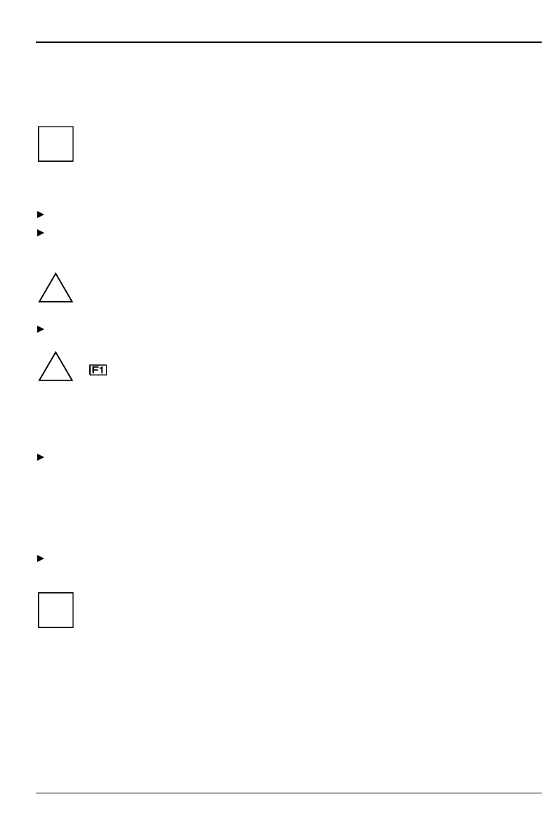
Switch your monitor on.
Switch the system unit on with the ON/OFF switch.
The power-on indicator lights green and the PC is started.
!While the PC boots, the screen remains dark for up to a minute depending on the system
configuration. To see the start-up messages, you can switch off this standard setting in
the BIOS Setup in the Quiet Boot entry.
Adjust the brightness if necessary (see the Operating Manual for the monitor).
!Some variants require you to start the software installation by pressing the function key
.
Once the installation has been started the PC must not be switched off.
You should only reboot the PC during installation if you are requested to do so. Otherwise
the installation will be not be performed correctly. If a fault occurs in the installation the
contents of the hard disk must be completely restored.
During installation follow the instructions on the screen.
Consult the operating system manual if there is anything unclear about the requested input data.
Some system configurations do not include a Windows CD in the delivery package. In this case you
should create a backup copy after installing Windows so that you can restore the hard disk contents
in an emergency.
You need about 40 diskettes for this.
Create Windows diskettes with the MSCSD backup program (create system diskettes) and label
them using the labels supplied.
iYou will find further information about the system, drivers, utilities, updates, and manuals
etc. on the "Drivers & Utilities" CD supplied.
Preparation for use and operation Switching the PC on and off
18 A26361-K520-Z100-4-7619
Switching on the PC
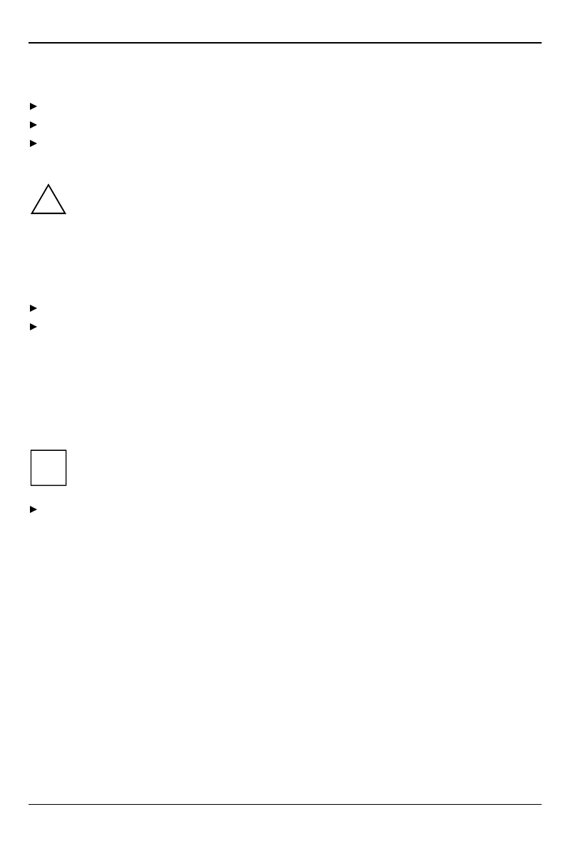
Switch the monitor on (see the Operating Manual for the monitor).
Switch the system unit on with the main switch at the rear of the system unit.
If the power-on indicator lights orange, press the ON/OFF switch at the front of the system unit.
The power-on indicator lights green and the PC is started.
!While the PC boots, the screen remains dark for up to a minute depending on the system
configuration. To see the start-up messages, you can switch off this standard setting in
the BIOS Setup in the Quiet Boot entry.
If you have assigned the system password, you must enter this when requested to do so,
in order to start the operating system.
Switching off the PC
Shut down the operating system properly. Windows in the Start menu via the Quit function.
If the operating system does not automatically switch the system unit off, switch the system
unit to ready-to-operate by pressing the ON/OFF switch or turn it off by pressing the main
switch when requested to do so.
If the system unit is ready-to-operate, the power-on indicator lights up orange. The system unit
consumes a minimum of energy and can be switched on by an external device (provided that the
remote-on functionality is set to Enabled in the BIOS Setup).
When the system unit is switched off with the main switch the power-on indicator is dark after
approx. 15 seconds. The system unit no longer uses any power.
iThe main switch and the ON/OFF switch do not disconnect the system unit from the line
voltage. To disconnect the line voltage completely, remove the power plug from the
socket.
Switch the monitor off (see the Operating Manual for the monitor).
Placing a PC (with soft power off function) in a ready-to-operate state by means of software
Prerequisite: Your system must support switching off with software and this functionality must be
enabled in BIOS Setup (Soft Power OFF - Enabled). In addition, the soft off software must be installed
on Windows NT systems.
You can switch your PC ready-to-operate under Windows 9x and Windows NT via the
Shutdown the Computer menu or by using the DeskOff program.
Indicators on the system unit Preparation for use and operation
A26361-K520-Z100-4-7619 19
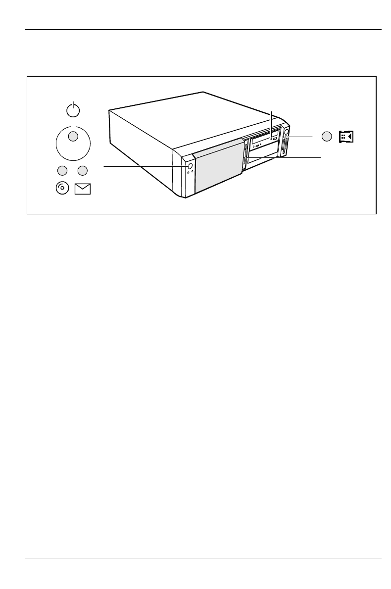
Indicators on the system unit
23
1
4
5
6
1 = Power-on indicator
2 = Hard disk indicator
3 = Message indicator
4 = CD-ROM indicator
5 = Chipcard reader indicator
6 = Floppy disk indicator
1 - Power-on indicator
− green:
The system unit is on.
− orange:
The system unit is ready-to-operate.
In this mode the PC consumes very little power and can be switched on at the ON/OFF
switch. If the remote-on function is Enabled in the BIOS Setup, the system unit can be
switched on by an incoming message (e. g. fax, telephone call).
− flashes green/orange:
The indicator only flashes on systems which support the ACPI function (Advanced
Configuration and Power Interface).
The system unit is in the energy-saving mode (standby). After being switched on with the
ON/OFF switch, the PC returns to the state it was in before the energy-saving mode. In
the energy-saving mode the system unit may not be switched off with the main switch or
disconnected from the mains supply, as this may otherwise result in data loss.
− does not glow:
The system unit is switched off.
2 - Hard disk indicator
The indicator lights up when the hard disk drive of the system unit is accessed.
3 - Message indicator
The display glows or flashes when the system has received a message or has reported a
malfunction. A detailed description can be found in the Technical Manual for the system board.
4 - CD-ROM indicator
The indicator lights up when the CD-ROM drive of the system unit is accessed. You may only
remove the CD when the indicator is dark.
Preparation for use and operation Keyboard
20 A26361-K520-Z100-4-7619
5 - Chipcard reader indicator
The indicator lights up when the chipcard reader is accessed. You may only remove the chipcard
when the indicator is dark.
6 - Floppy disk indicator
The indicator lights up when the floppy disk drive of the system unit is accessed. You may only
remove the floppy disk when the indicator is dark.
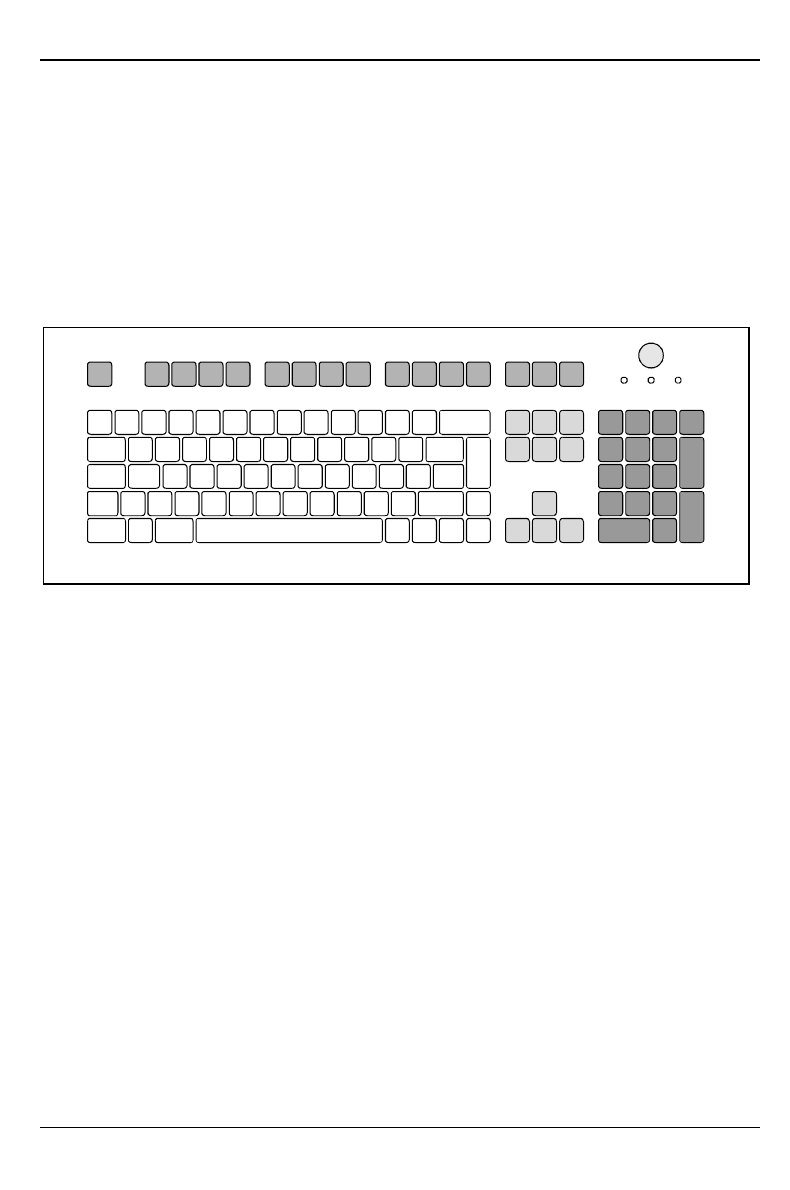
Keyboard
1
34
5
2
1 = Function keys
2 = ON/OFF switch (optional)
3 = alphanumeric keypad
4 = Cursor control keys
5 = numeric keypad (calculator keypad)
Keyboard Preparation for use and operation
A26361-K520-Z100-4-7619 21
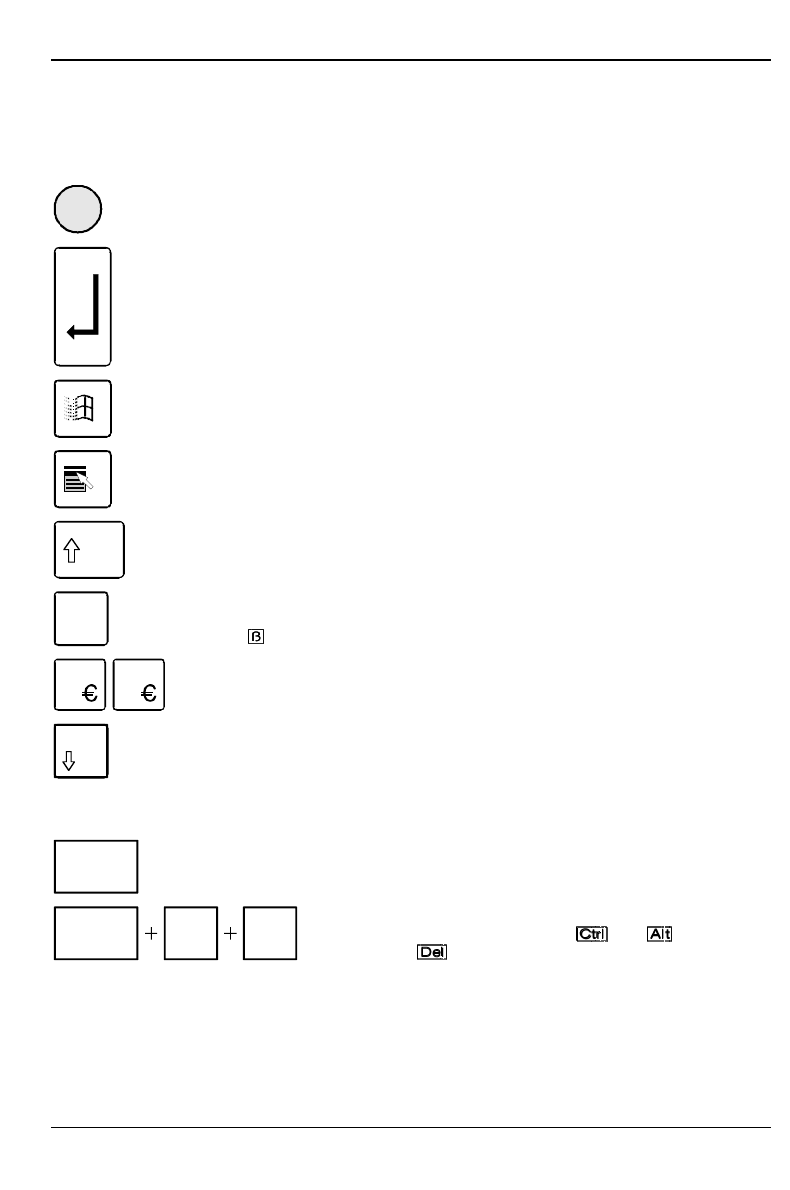
Important keys and key combinations
The following description of keys and key combinations refers to MS Windows. Details of other keys
and key combinations can be found in the documentation of the relevant application program.
ON/OFF switch
Depending on the setting in the BIOS setup, the system can be switched on, off or on
and off with this switch.
Enter key
confirms or starts the marked selection. The enter key is also referred to as the
"Return" key or "Carriage Return".
Start key
invokes the START menu of Windows.
Menu key
invokes the menu for the marked item.
Shift key
enables upper-case letters and the upper key symbols to be displayed.
Alt Gr Alt Gr (e.g. German keyboard)
produces a character shown on the right-hand side of a key (e. g. the character "\"
on the key ).
%
5
$
4
Euro key
enables the output of the euro symbol.
Num Num Lock key
by pressing the Num Lock key you switch between the upper- and lower-case levels
of the calculator keypad.
At upper-case level (Num Lock indicator lit) the digit and comma keys are active.
At lower-case level (Num Lock indicator not lit) the cursor control functions are
active in the calculator keypad.
Ctrl
Ctrl key
starts key combination actions.
Ctrl Alt Del
Warm boot
restarts your PC. First hold down the and key, and
then press the key. With Windows 9x the Task Manager
appears first. The warm start is then carried out the second
time.
Preparation for use and operation Working with floppy disks
22 A26361-K520-Z100-4-7619
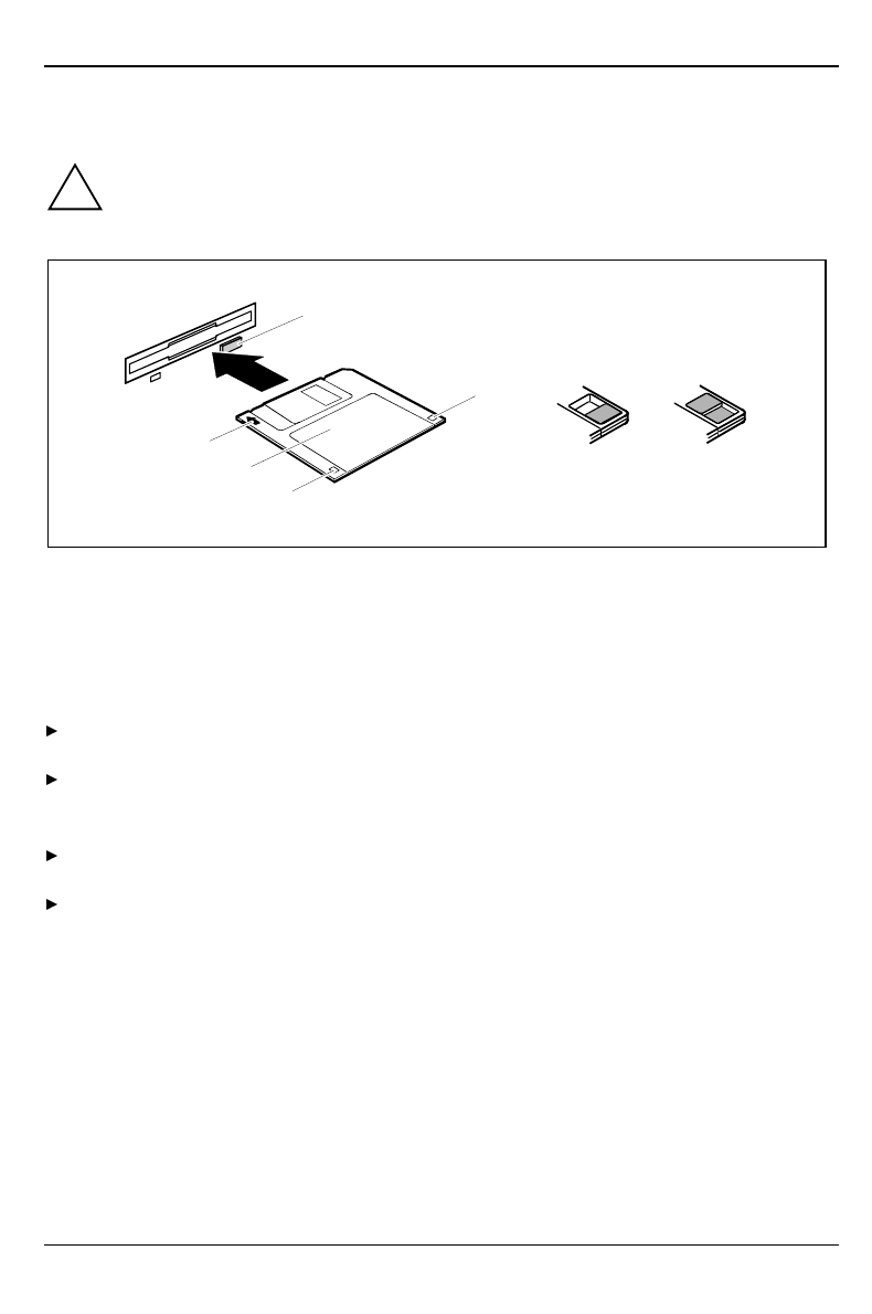
Working with floppy disks
!Follow the instructions supplied by the vendor of the floppy disks.
Never clean the floppy disk drives with cleaning disks. Even just one attempt would
destroy the read/write head in the disk drive within 20 seconds.
3
2
1
5
6
47
1 = Insertion direction
2 = Label area
3 = Write protection tab for a 720 Kbyte or a 1.44 Mbyte floppy disk
4 = Identification of a 1.44 Mbyte floppy disk or write protect tab on a 120 Mbyte floppy disk
5 = Eject button for inserted floppy disks
6 = Floppy disk is write-protected
7 = Floppy disk is not write-protected
To insert a floppy disk, push it into the drive in the insertion direction (1) until it engages. The
label should be facing upward.
To remove the floppy disk, press the eject button (5).
The write-protect slider enables you to protect the data on the floppy disk from inadvertent
overwriting or deletion.
To protect the data on the floppy disk from being overwritten, push the write-protect slider to
position (6). The hole is now visible.
To remove write protection, push the slider to position (7). The hole is now covered.

Settings in BIOS Setup Preparation for use and operation
A26361-K520-Z100-4-7619 23
Settings in BIOS Setup
The BIOS Setup
menu allows you to set your hardware configuration and system functions. When the
PC is delivered, the default entries are valid (see Technical Manual for the system board or in the
manual "BIOS Setup"). You can customize these settings to your requirements in BIOS Setup.
The technical manual of the system board or the "BIOS Setup" manual shows you how to open and
use the BIOS Setup. The menus and setting options provided by BIOS-Setup are also described in
detail.
Property and data protection
The software functions and mechanical lock on your PC enables you to protect your system and
personal data in a number of ways against unauthorized access. By combining these options, you
can achieve optimum protection for your system.
Locking the system unit mechanically
With the casing lock you can mechanically lock the system unit, and with the drive cover you can
block access to the drives.
Access authorization via chipcard
In systems that are equipped with a chipcard reader, access can be restricted to users who have a
corresponding chipcard.
Security functions under Windows
Under MS-Windows you can activate a screen saver and protect it with a password. Only those
users who know the password can deactivate the screen saver and access any open files. Detailed
information on screen savers under MS Windows is provided by the associated help function.
Security functions under Windows NT
You can use the SSLAUNCH program to start the screen saver POWERSAVER immediately. These
programs are located on the "Drivers & Utilities" CD.
Information on POWERSAVER and SSLAUNCH can be found in the POWERSAV.HLP and
SSLAUNCH.EXE files.
Security functions under Windows 9x
You can lock the keyboard and mouse with a password-protected screen saver.
Preparation for use and operation Property and data protection
24 A26361-K520-Z100-4-7619
BIOS Setup security functions
The Security menu in BIOS Setup offers you various options for protecting your personal data against
unauthorized access, e. g.:
• Preventing unauthorized BIOS Setup calls
• Preventing unauthorized system access
• Preventing unauthorized access to the settings of boards with their own BIOS
• Preventing system booting from the diskette drive
• Activating virus warnings
• Preventing unauthorized writing of diskettes
• Protecting BIOS from overwriting
• Protecting the PC from being switched on by an external device
By combining these options, you can achieve optimum protection for your system.
You will find a detailed description of the Security menus and how to assign passwords in the
Technical Manual for the system board or in the "BIOS Setup" manual.
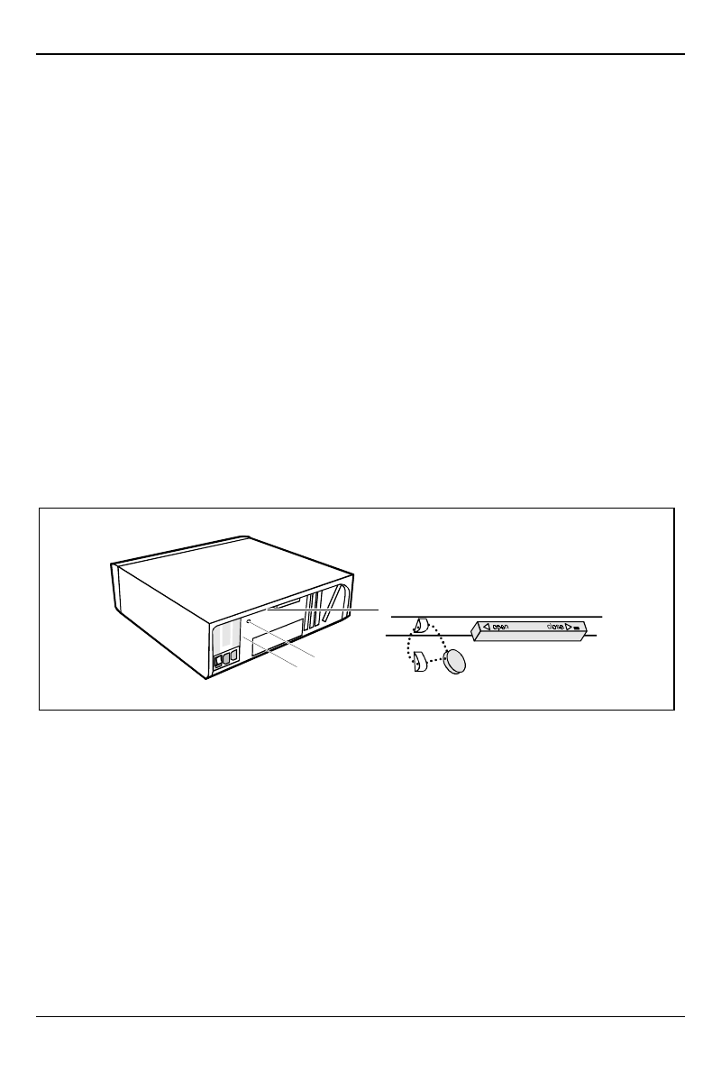
Theft protection and lead sealing
With a chain lock and the hole in the tab (1) or with the Kensington Lock device (2) and with a
Kensington MicroSaver you can protect your unit from theft.
To prevent unauthorized persons from opening the system unit, the casing can be lead-sealed. To
do this, use the eyes on the back of the casing.
2
1