Fujitsu Technology Solutions SCENIC6651 personal computer User Manual A26361 K520 Z100 4 7619
Fujitsu Technology Solutions GmbH personal computer A26361 K520 Z100 4 7619
Contents
- 1. Manual Scenic 600 Oct 99 part 1
- 2. Manual Scenic 600 Oct 99 part 2
- 3. Manual Scenic 600 Oct 99 part 3
- 4. Manual Scenic 600 Oct 99 part 4
- 5. Manual Scenic 600 Oct 99 part 5
- 6. Manual Scenic 600 Oct 99 part 6
- 7. Manual Scenic 600 Oct 99 part 7
- 8. Scenic 600 Scenic xB May 2000 part1
- 9. Scenic 600 Scenic xB May 2000 part2
- 10. Scenic 600 Scenic xB May 2000 part3
- 11. Scenic 600 Scenic xB May 2000 part4
Manual Scenic 600 Oct 99 part 4

A26361-K520-Z100-4-7619 25
Troubleshooting and tips
!Take note of the safety notes in the manual "Safety, Guarantee and Ergonomics" and in
the chapter "Preparation for use and operation", when you connect or disconnect cables.
If a fault occurs, try to correct it as described:
• in this chapter
• in the documentation of the connected devices
• in the help systems of the software used.
If you fail to correct the problem, proceed as follows:
Switch the PC off.
Make a note of the steps and the circumstances that led to the fault. Also make a note of any
error messages displayed and the Ident-No. of your device.
Contact your sales outlet or our customer service center.
Installing new software
When installing programs or drivers, important files may be overwritten and modified. To be able to
access the original data in the case of any problems following installation, you should backup your
hard disk prior to installation.
Power-on indicator remains dark after you have
switched on your device
This may have the following causes:
The line voltage supply is faulty
Check that the power cable is plugged properly into the system unit and grounded power outlet.
Switch the PC on at the main switch.
Internal power supply overloaded
Disconnect the power plug of the system unit from the grounded power outlet.
Wait for a moment.
Plug the power plug into the grounded power outlet again.
Switch the PC on at the main switch.

Troubleshooting and tips
26 A26361-K520-Z100-4-7619
The screen stays blank
If your screen remains blank this may have the following causes:
Monitor is switched off
Switch your monitor on.
The PC starts
While the PC boots, the screen remains dark for up to a minute depending on the system
configuration. To see the start-up messages, you can switch off this standard setting in the BIOS
Setup in the Quiet Boot entry.
Screen has been blanked
Press any key on the keyboard.
or
Deactivate screen blanking (screen saver). Enter the appropriate password.
Brightness control is set to dark
Set the brightness control to bright. For detailed information, please refer to the Operating
Manual supplied with your monitor.
Power cable or monitor cable not connected
Switch off the monitor and the system unit.
Check that the power cable is properly connected to the monitor and system unit or to the
grounded power outlet.
Check that the monitor cable is properly connected to the system unit and monitor (if not
permanently attached).
Switch on the monitor and the system unit.
Wrong monitor has been set under Windows NT
Restart the PC in standard VGA mode.
Set the desired resolution in the Control Panel window using the Display program, and adjust
the monitor display as described in the Operating Manual.
Wrong monitor has been set under Windows 9x
Restart the PC.
If the message Starting Windows 9x appears, press function key .
The Windows 9x start menu appears.
Select the option Safe mode or Safe mode with network support.
Set the correct values for the attached monitor by selecting Start - Settings - Control Panel -
Display - Settings.
The wrong RAM memory modules have been inserted
See the Technical Manual for the system board for information on which memory modules can be
used.

Troubleshooting and tips
A26361-K520-Z100-4-7619 27
No mouse pointer displayed on the screen
Shut down the operating system properly.
Switch the PC off.
Check that the mouse cable is properly connected to the system unit.
If you use an adapter or extension lead with the mouse cable, check the connections.
Make sure that only one mouse is connected.
Switch the PC on.
The mouse controller must be enabled, if you use a PS/2 mouse. Check in the BIOS Setup that
the mouse controller is enabled.
Check that the mouse driver is properly installed and is present when the application program
is started. Detailed information can be found in the User Guide of the mouse or application
program.
The floppy disk cannot be read or written
Check that the write protection of the floppy disk or the floppy disk drive is activated (refer also
to the Technical Manual of the system board or in the manual BIOS).
Check the relevant entries for Diskette A: or B: in the Main menu of the BIOS Setup.
Check that the floppy disk drive controller is enabled (refer also to the Technical Manual of the
system board or in the manual "BIOS Setup").
Check that the cables of the floppy disk drive are properly connected (refer to chapter "System
expansions").
Time and/or date is not correct
Set the time and/or date. You can set the time and date in the BIOS Setup or in the operating
system.
iIf the time and date are repeatedly wrong when you switch on your PC, the battery is flat.
Change the lithium battery as described in the Chapter "System expansions".
Error messages on the screen
Error messages and their descriptions are listed in the Technical Manual of the system board or in
the "BIOS Setup" manual and in the documentation of the installed software.

Troubleshooting and tips
28 A26361-K520-Z100-4-7619
Restoring the hard disk contents
Instructions for this purpose can be found in the documentation (booklet) of the
CD "Drivers & Utilities".
Tips
The PC cannot be switched off with the ON/OFF switch
Cause: The PC has not been switched on with the ON/OFF switch.
Press the ON/OFF switch again.
Cause: System crash
Press the ON/OFF switch for at least four seconds, until the device switches off.
PC switches on briefly and then off again
The power cable has been plugged in or the device was switched on with the main switch. For
technical reasons, this brief switching on and off is necessary.
Out of system resources
If you have too many applications running at once, you may experience problems due to a lack of
system resources. If this happens, you should close applications you do not require or call the
applications in a different order.
BIOS settings in power management do not become active
The Auto insert notification setting may be active for the CD-ROM drive. This setting causes
Windows 9x to inquire about any modifications on the drive at regular intervals. Because of this the
timer for the idle time cannot time out.
To activate power management, proceed as follows:
In Windows 9x, select Start - Settings - Control Panel - System - Device Manager - CD-ROM.
Select the installed CD-ROM drive from the list.
Select Settings.
Deactivate the Auto insert notification box.
CD-ROM drive
Information on the CD-ROM drive can be found in the manual of the CD-ROM drive or on the
"Drivers & Utilities“ CD.
Other manuals
Other manuals are contained on the "Drivers & Utilities" CD.

A26361-K520-Z100-4-7619 29
System expansions
!It may be necessary to update the BIOS when carrying out a system expansion or
hardware upgrade. In this instance, please contact our customer service center.
When installing components with a high power loss, make sure that the maximum
permissible temperatures of the individual components are not exceeded.
The device must be switched off when installing/removing the extensions and may not be
in the Suspend mode.
This chapter describes all the activities required to modify your PC hardware (e.g. installing boards
or drives).
Memory and processor upgrading are described in the Technical Manual for the system board.
Read the supplied documentation before installing new drives and/or boards.
Refer to the Technical Manual for the system board before making any extensions on the system
board.
Opening the system unit
Switch the PC off.
!Please take note of the safety information in the chapter "Important notes".
Pull the power plug out of the power outlet!
If any cables attached to the system unit are obstructing you, pull out the connectors on the
system unit.
Place the system unit in a convenient working position.
System expansions
30 A26361-K520-Z100-4-7619
2
a
3 4
1
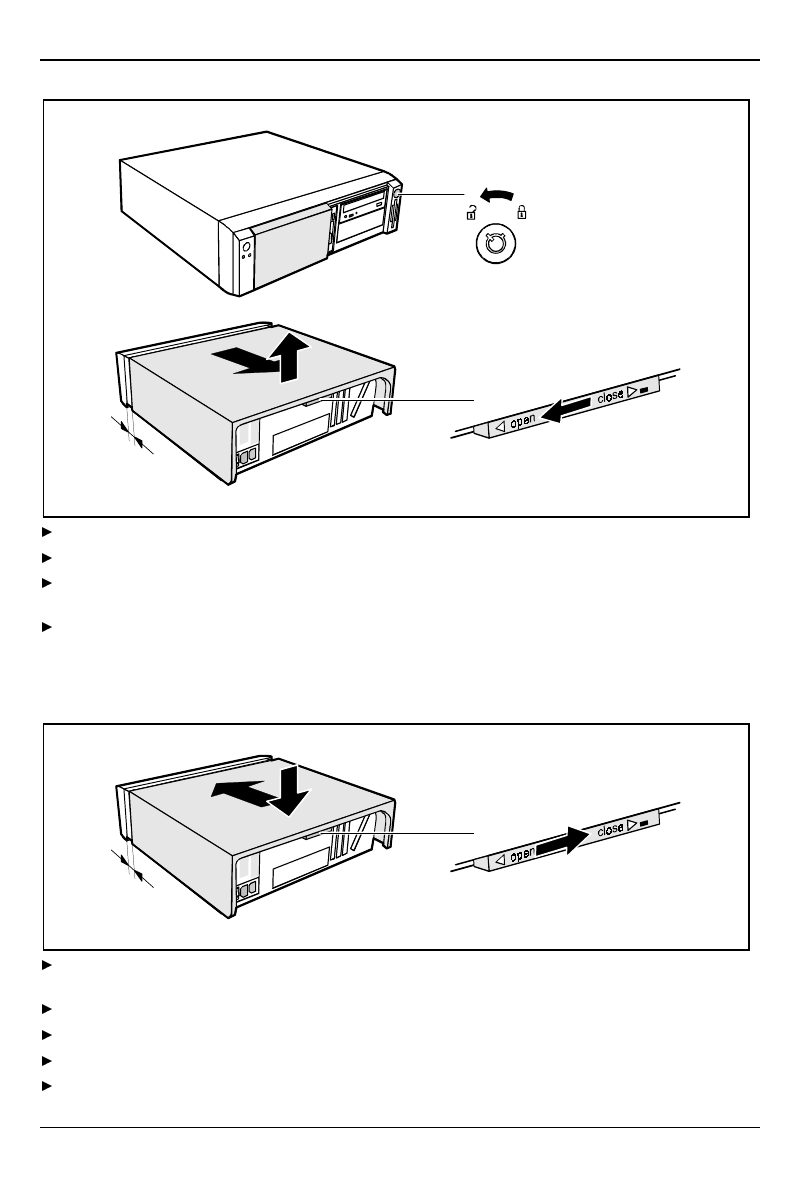
Unlock the system unit (1).
Unlock the top cover with the locking slide at the rear of the casing by sliding it to the left (2).
Push the top cover in the direction of the arrow (3) until the distance (a) is
approximately 10 mm.
Lift off the top cover in an upward direction (4).
Assembling the system unit
3
a
2 1
Place the top cover on the system unit (1) from above so that the distance (a) is
approx. 10 mm.
Push the top cover in the direction of the arrow (2) until it engages.
Lock the top cover using the locking slide at the rear (3).
Return the system unit to its original position.
If you have disconnected cables, reconnect them at the rear.
System expansions
A26361-K520-Z100-4-7619 31
Installing and removing a board
!Observe the notes on installing and removing boards in the chapter "Important notes".
Old ISA boards which require a -5 V power supply are not supported.
The number, position and constellation of the board slots on the system board can be found in the
technical manual for the system board. Boards may be installed when the device is shipped.
Any angled slot is intended for high PCI boards including connectors and cables. However, you can
also install an ISA board.
Installing a board
Open the system unit (see "Opening the system unit").
3
1
2
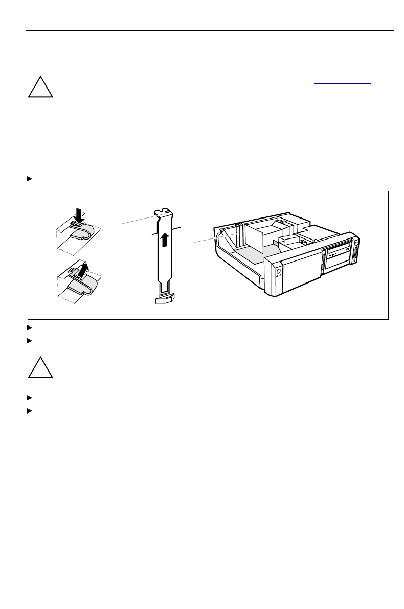
Press on the clip in the direction of the arrow (1) and remove it (2).
Remove the rear slot cover plate from the slot (3).
!Do not dispose of the rear slot cover plate. For cooling, protection against fire and in order
to comply with EMC regulations, you must refit the rear slot cover plate if you remove the
board.
Take the new board out of its packaging.
Make the required settings for the board.
System expansions
32 A26361-K520-Z100-4-7619
1
a
3
2
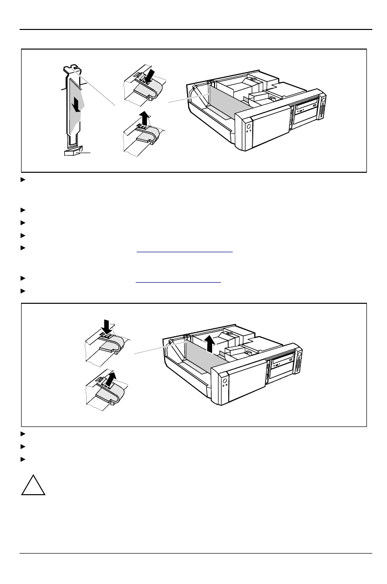
Push the board up to its slot (1).
Ensure that the end of a long board without angle bracket fits into the corresponding guide of
the system unit. Ensure also that the point of the angle bracket slots into guide (a).
Press the board into the slot so that it engages.
Replace the clip (2) which fixes the board. Make sure that the clip engages when released (3).
If necessary, plug the lines on the board.
Close the system unit (see "Assembling the system unit").
Removing a board
Open the system unit (see "Opening the system unit").
Remove the lines connected to the board.
3
1
2
Press on the clip in the direction of the arrow (1) and remove it (2).
Remove the board from the system unit (3).
Place the board into an appropriate packaging.
!For cooling, protection against fire and in order to comply with EMC (electromagnetic
compatibility) regulations, you must refit the rear slot cover plate.