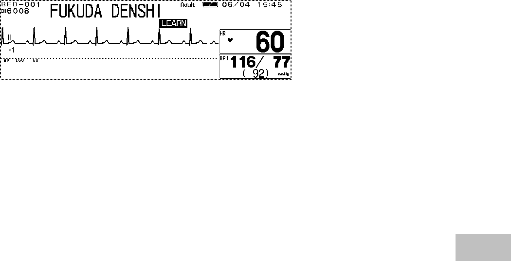
Fukuda Denshi Co DS7100 Patient Monitor User Manual DS71v1 1 FA 06 Parameter 008
Fukuda Denshi Co Ltd Patient Monitor DS71v1 1 FA 06 Parameter 008
Contents
Manual 7

6−1
Parameter Setup
Chapter 6
− Parameter Setup −
Setting the Monitoring Condition ・・・・・・・・・・・・・・2
To Display the Parameter Setup Menu・・・・・・・・・・・2
Zero Balance of All Pressure Lines (BP1, BP2) ・・・3
− ECG −・・・・・・・・・・・・・・・・・・・・・・・・・・・・・・・・・・・・・4
ECG Waveform Size and Lead ・・・・・・・・・・・・・・・・・4
HR Alarm・・・・・・・・・・・・・・・・・・・・・・・・・・・・・・・・・・・・6
Arrhythmia Alarm ・・・・・・・・・・・・・・・・・・・・・・・・・・・・・6
Filter Mode Selection・・・・・・・・・・・・・・・・・・・・・・・・・・7
HR Average Selection ・・・・・・・・・・・・・・・・・・・・・・・・・8
HR Synchronized Indicator (ON/OFF of HR
Synchronized Tone)・・・・・・・・・・・・・・・・・・・・・・・・・・・8
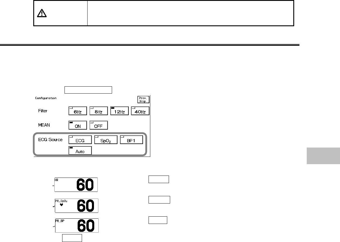
ECG Source ・・・・・・・・・・・・・・・・・・・・・・・・・・・・・・・・・9
Automatic Lead Switching・・・・・・・・・・・・・・・・・・・・・・9
Pacemaker Pulse・・・・・・・・・・・・・・・・・・・・・・・・・・・・10
QRS Pace Mask・・・・・・・・・・・・・・・・・・・・・・・・・・・・・11
ECG Drift Filter ・・・・・・・・・・・・・・・・・・・・・・・・・・・・・・12
ON/OFF of Parameter Display・・・・・・・・・・・・・・・・・13
− Respiration −・・・・・・・・・・・・・・・・・・・・・・・・・・・・・・14
Respiration Waveform Size ・・・・・・・・・・・・・・・・・・・14
RR Alarm・・・・・・・・・・・・・・・・・・・・・・・・・・・・・・・・・・・15
Apnea Alarm ・・・・・・・・・・・・・・・・・・・・・・・・・・・・・・・・15
CVA Detection ・・・・・・・・・・・・・・・・・・・・・・・・・・・・・・16
Respiration Source ・・・・・・・・・・・・・・・・・・・・・・・・・・17
Impedance Respiration Measurement ・・・・・・・・・・17
RR Synchronization Mark ・・・・・・・・・・・・・・・・・・・・・18
ON/OFF of Parameter Display・・・・・・・・・・・・・・・・・19
− Invasive Blood Pressure (BP1, BP2)−・・・・・・・・・・20
BP Scale (BP1, BP2)・・・・・・・・・・・・・・・・・・・・・・・・・20
BP Alarm (BP1, BP2)・・・・・・・・・・・・・・・・・・・・・・・・・21
Zero Balance of Pressure Lines (BP1, BP2) ・・・・・21
Filter Selection (BP1, BP2)・・・・・・・・・・・・・・・・・・・・22
Mean BP Display (BP1, BP2)・・・・・・・・・・・・・・・・・・22
ECG Source (BP1)・・・・・・・・・・・・・・・・・・・・・・・・・・・23
ON/OFF of Parameter Display・・・・・・・・・・・・・・・・・24
− SpO2 −・・・・・・・・・・・・・・・・・・・・・・・・・・・・・・・・・・・・25
SpO2 Waveform Size・・・・・・・・・・・・・・・・・・・・・・・・・26
SpO2 Alarm ・・・・・・・・・・・・・・・・・・・・・・・・・・・・・・・・・26
ECG Source ・・・・・・・・・・・・・・・・・・・・・・・・・・・・・・・・27
SpO2 Alarm during NIBP Measurement (Ignore
NIBP) ・・・・・・・・・・・・・・・・・・・・・・・・・・・・・・・・・・・・・・27
ON/OFF of Parameter Display・・・・・・・・・・・・・・・・・28
− Non-Invasive Blood Pressure −・・・・・・・・・・・・・・・29
NIBP Automatic Measurement・・・・・・・・・・・・・・・・・29
NIBP 1-Minute Interval Measurement・・・・・・・・・・・30
Quick SYS Start ・・・・・・・・・・・・・・・・・・・・・・・・・・・・・31
NIBP Alarm ・・・・・・・・・・・・・・・・・・・・・・・・・・・・・・・・・31
Quick SYS Measurement Duration・・・・・・・・・・・・・32
End of Measurement Tone・・・・・・・・・・・・・・・・・・・・33
Quick SYS List・・・・・・・・・・・・・・・・・・・・・・・・・・・・・・33
PR Display ・・・・・・・・・・・・・・・・・・・・・・・・・・・・・・・・・ 34
Mean BP Display・・・・・・・・・・・・・・・・・・・・・・・・・・・・ 34
1-Minute Measurement Duration・・・・・・・・・・・・・・・ 35
NIBP Speed ・・・・・・・・・・・・・・・・・・・・・・・・・・・・・・・・ 35
− Temperature −・・・・・・・・・・・・・・・・・・・・・・・・・・・・・36
Temperature Alarm ・・・・・・・・・・・・・・・・・・・・・・・・・・ 36
ON/OFF of Parameter Display ・・・・・・・・・・・・・・・・37
− CO2 Concentration − (DS-7141)・・・・・・・・ 38
CO2 Scale ・・・・・・・・・・・・・・・・・・・・・・・・・・・・・・・・・・38
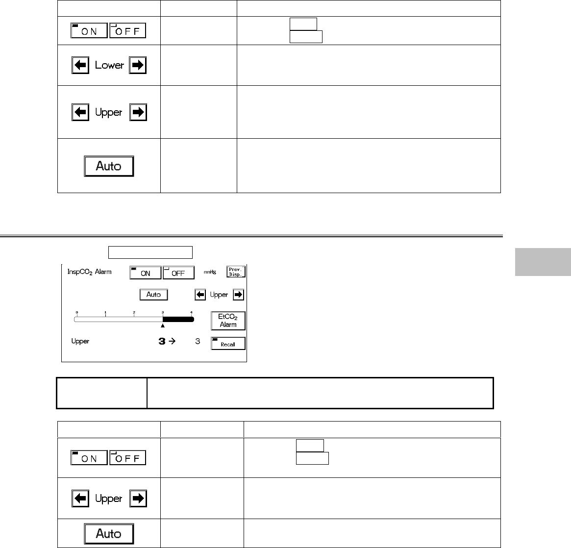
EtCO2 (End-Tidal CO2) Alarm ・・・・・・・・・・・・・・・・・ 38
InspCO2 (Inspiratory CO2) Alarm ・・・・・・・・・・・・・・・39
EtCO2 Average Duration・・・・・・・・・・・・・・・・・・・・・・40
Measurement Unit ・・・・・・・・・・・・・・・・・・・・・・・・・・・40
CO2 Calibration ・・・・・・・・・・・・・・・・・・・・・・・・・・・・・41
Restarting the CO2 Unit ・・・・・・・・・・・・・・・・・・・・・・ 42
ON/OFF of Parameter Display ・・・・・・・・・・・・・・・・42
6
Parameter Setup
6−2
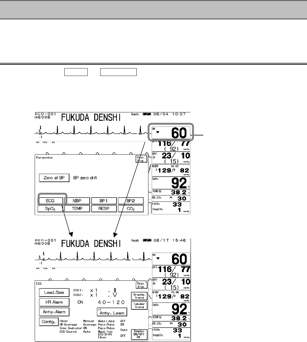
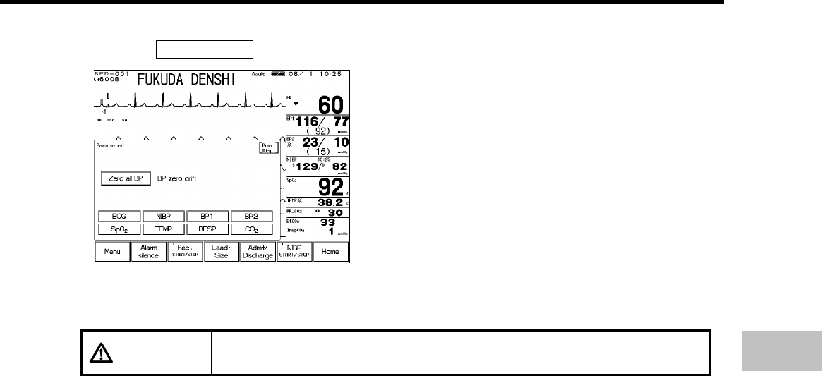
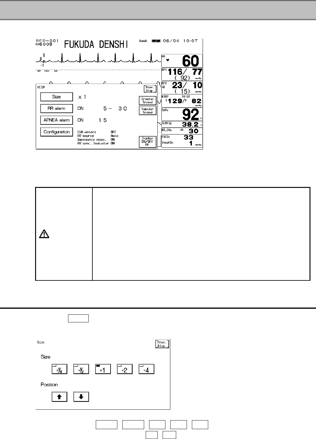
− Parameter Setup −Setting the Monitoring Condition
This menu allows setup of measurement condition, waveform size, scale, etc. of ECG, BP, NIBP,
SpO2, RESP, TEMP, and CO2.
To Display the Parameter Setup Menu
Press the Menu → Parameter keys to display the parameter setup menu, and select the
parameter. On the parameter setup menu, BP zero balance can be performed.
The parameter setup menu for each parameter can be also accessed by pressing the parameter
key where numeric data is displayed.
<Parameter Setup Menu>
<ECG Parameter Setup Menu>
Parameter Key
6−3
Zero Balance of All Pressure Lines (BP1, BP2)
1. Open the three-way cock of all pressure transducers to air.
2. Press the Zero All BP key.
Verify the BP waveform is positioned at zero, and “0”
is displayed for the BP value. A message, “BP zero
complete” will be displayed when the procedure is
complete. A message, “BP zero failed” will be
displayed when the process fails. The three-way
cock may not be opened to air, artifact may be
present, or the transducer may be defective.
Check the cause and try the zero balance procedure
again.
A message, “BP zero drift” will be displayed when the
interface cable is not connected. Check if the cable
is firmly connected.
3. Close the three-way cock when the zero balance is complete.
CAUTION Each time the blood pressure transducer or tubing is replaced, the zero
balance procedure is required to ensure accurate measurements.6
Parameter Setup
6−4
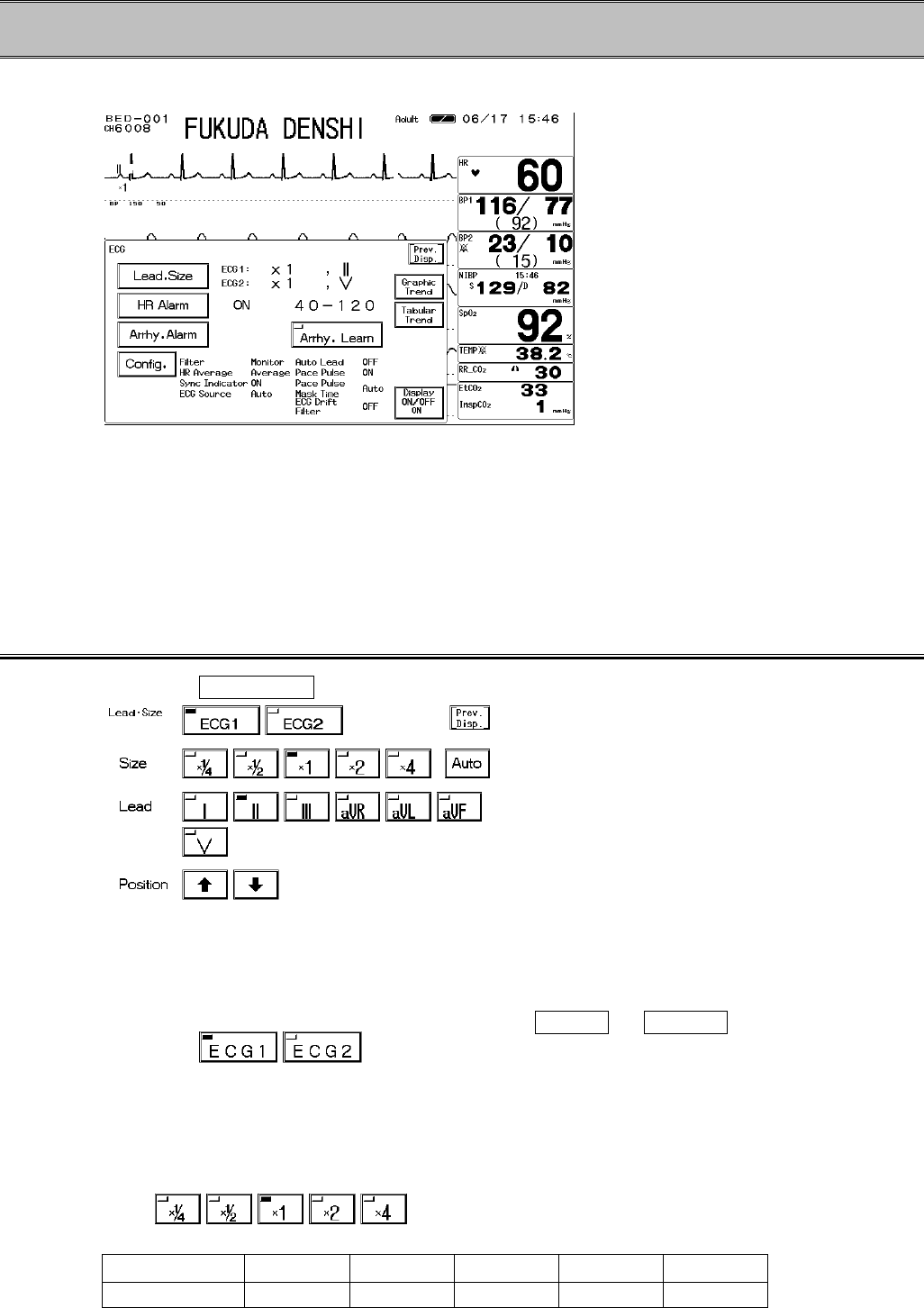
− ECG −
The measurement condition for ECG can be set on this menu.
Lead, Size : Sets the waveform size and lead for ECG display and recording.
HR Alarm :Sets ON/OFF of HR alarm, and sets upper and lower alarm limit.
Arrhy. Alarm :Sets ON/OFF and detection threshold for each arrhythmia alarm.
Configuration :Sets the condition for measuring ECG and HR.
Arrhy. Learn :The monitor learns the normal QRS at ECG electrode replacement or at
misdetection of the arrhythmia analysis.
ECG Waveform Size and Lead
1. Press the Lead, Size key to display the size / lead setup menu.
2. Select ECG1 or ECG2.
If 4-electrode or 5-electrode ECG relay cable is used,
2 channels of ECG can be measured.
Select ECG1 or ECG2 key to set the
waveform size, lead, baseline position. The key
LED for the selected channel will light.
When 3-electrode is used, these keys will not be
displayed.
3. Select the waveform size.
Select the waveform size for displaying and
recording.
Size ×1/4 ×1/2 ×1×2×4
Voltage (10mm) 4mV 2mV 1mV 500uV 250uV
6−5
Pressing the Auto key will automatically adjust the
ECG amplitude to 10mm.
The automatic adjustment will function only when the
key is pressed.
The automatic adjustment will not function when the
monitor is learning arrhythmia.
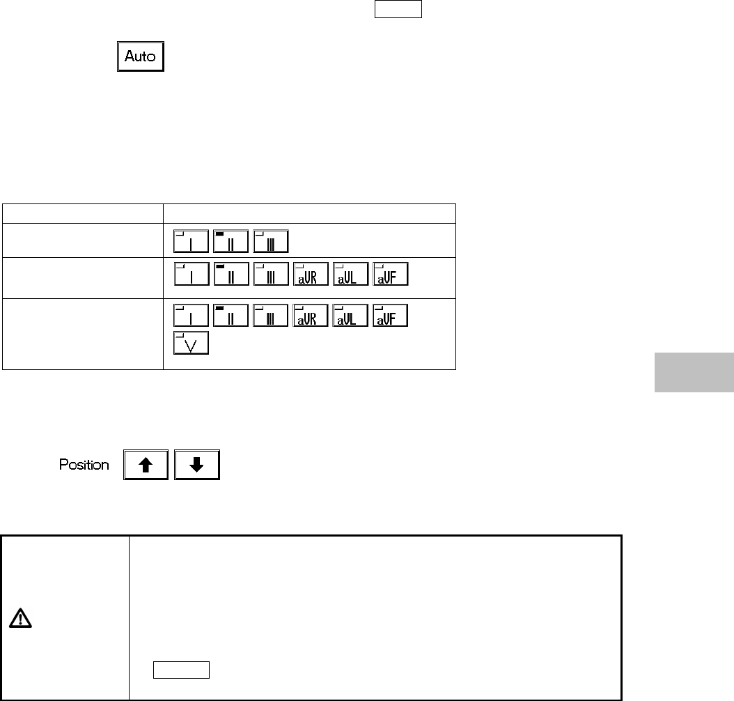
4. Select the lead.
The leads can be selected from 3 leads, 6 leads, 7 leads depending on the connected ECG relay
cable.
ECG Relay Cable Lead
3-electrode
4-electrode
5-electrode
5. Set the baseline position.
If the waveform is difficult to see due to ECG
amplitude, set the 0mV baseline position.
The baseline position for the waveform display and
recording will be adjusted.
CAUTION
?
The threshold level for arrhythmia detection changes with ECG
waveform size. Set a proper waveform size for monitoring.
When the ECG waveform size is ?1/4, ?1/2, or ?1, the detection
threshold is 250 µV.
When the ECG waveform size is ?2, or ?4, the detection threshold is
150 µV.
?
Automatic size/position of the ECG is effective only at the time the
AUTO key is pressed. This does not continually adjust size and
position.
6
ECG
6−6
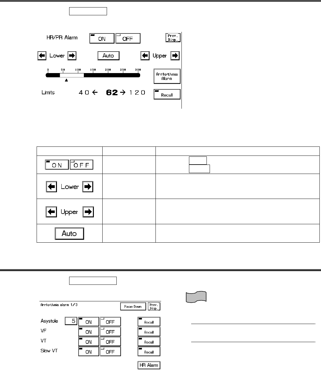
HR Alarm
1. Press the HR Alarm key to display the alarm setup menu.
Select ON/OFF of HR/PR alarm, and set the upper and lower alarm limit.
The common alarm value for HR measured from ECG, PR measured from SpO2, PR measured
from BP can be set.
The upper and lower limit can be set in 5 bpm increments.
Key Item Description
Individual Alarm Selecting ON will generate the HR/PR alarm.
Selecting OFF will not generate the HR/PR alarm.
Lower Alarm
Limit
Sets the lower alarm limit (20∼295bpm).
Setting a value 20bpm or below will turn OFF the
alarm.
Upper Alarm
Limit
Sets the upper alarm limit (25∼300bpm).
Setting a value 300bpm or above will turn OFF the
alarm.
Automatic
Setup Automatically sets the upper limit to +40bpm, and the
lower limit to −40bpm to the current value.
Arrhythmia Alarm
1. Press the Arrhy. Alarm key to display the arrhythmia alarm setup menu.
ON/OFF of each arrhythmia alarm and analysis threshold level can be set.
Reference
Refer to “4. Monitoring Setup Alarm Setup”
for details.
6−7
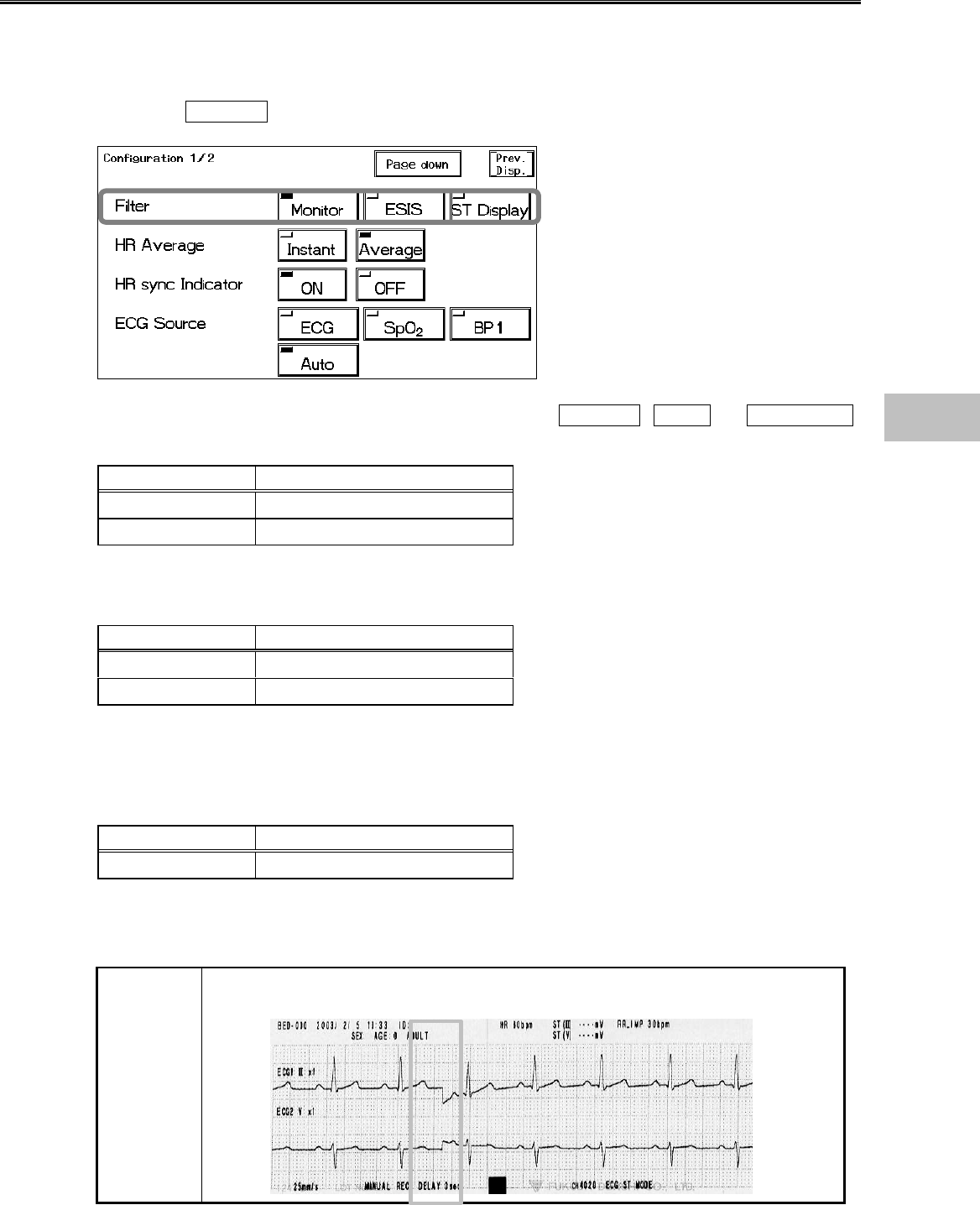
Filter Mode Selection
The waveform frequency characteristic can be selected from Monitor Mode, ESIS Mode, or ST
Display Mode according to the monitoring purpose. Each mode has different frequency
characteristic. The AC filter is always set to ON.
1. Press the Config. key to display the setup menu for selecting the filter.
2. Select a frequency characteristic to monitor ECG from Monitor , ESIS , or ST Display .
Monitor Mode
Patient Type Frequency Characteristic
Adult / Child 0.5∼40Hz
Neonate 1.6∼40Hz
This is the standard mode for ECG monitoring. The upper frequency is set to 40Hz to reduce
artifact caused by EMG, etc.
ESIS Mode
Patient Type Frequency Characteristic
Adult / Child 1.6∼15Hz
Neonate 1.6∼15Hz
This mode is for ECG monitoring when using electrosurgical instruments. The upper frequency is
set to 15Hz which will largely reduce the artifact caused by surgical knife, EMG, etc. However, as
this may also reduce the QRS amplitude at the same time, do not select this mode unless using
electrosurgical instruments.
ST Display Mode
Patient Type Frequency Characteristic
Adult / Child 0.05∼40Hz
Select this mode if ST measurement is the main purpose of ECG monitoring.
As the lower frequency is set to 0.05Hz, ST level can be accurately measured. If “Neonate” is
selected as patient type, this mode can not be selected
NOTE
When the filter setup is changed, a notch will appear on the ECG waveform due
to the change in frequency characteristic.
6
ECG
6−8
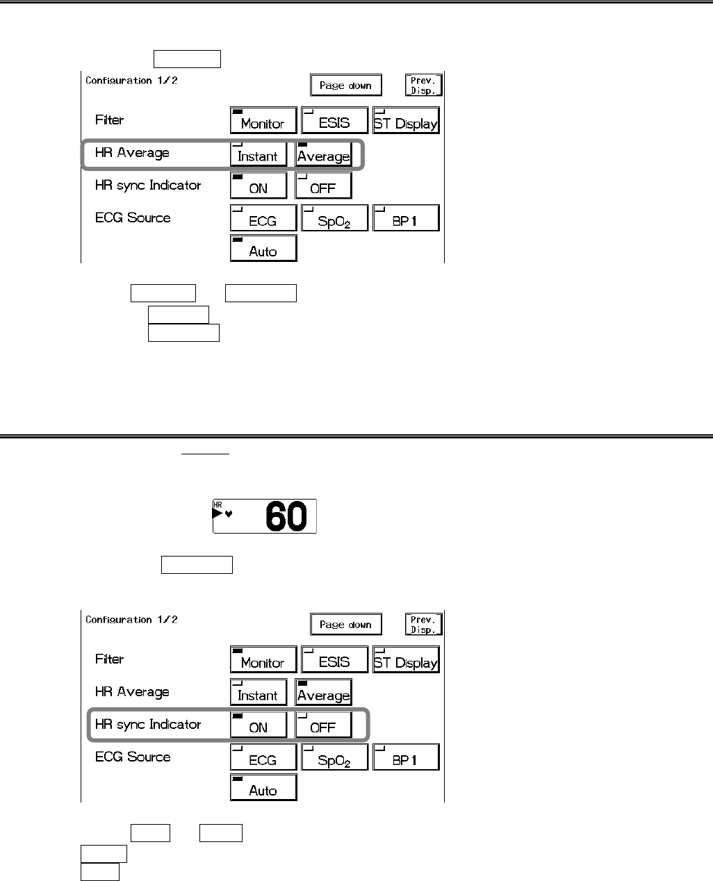
HR Average Selection
The averaging method of HR measured from ECG can be selected.
1. Press the Config. key to display the setup menu for HR Average selection.
2. Select Instant or Average .
Selecting Instant will display the HR measured from RR interval of each heartbeat.
Selecting Average will display the HR measured from 6 seconds of heartbeat for adult and
child, and 3 seconds of heartbeat for neonate.
HR Synchronized Indicator (ON/OFF of HR Synchronized Tone)
The HR mark synchronized to ECG or PR can be displayed inside the parameter key.
ON/OFF of HR synchronized tone can be also set.
HR Mark
1. Press the Config. key to display the setup menu for HR synchronized indicator
selection.
2. Select ON or OFF .
OFF will not display the synchronized mark. The synchronized tone will not be generated.
ON will display the synchronized mark. The synchronized tone will be generated.
6−9
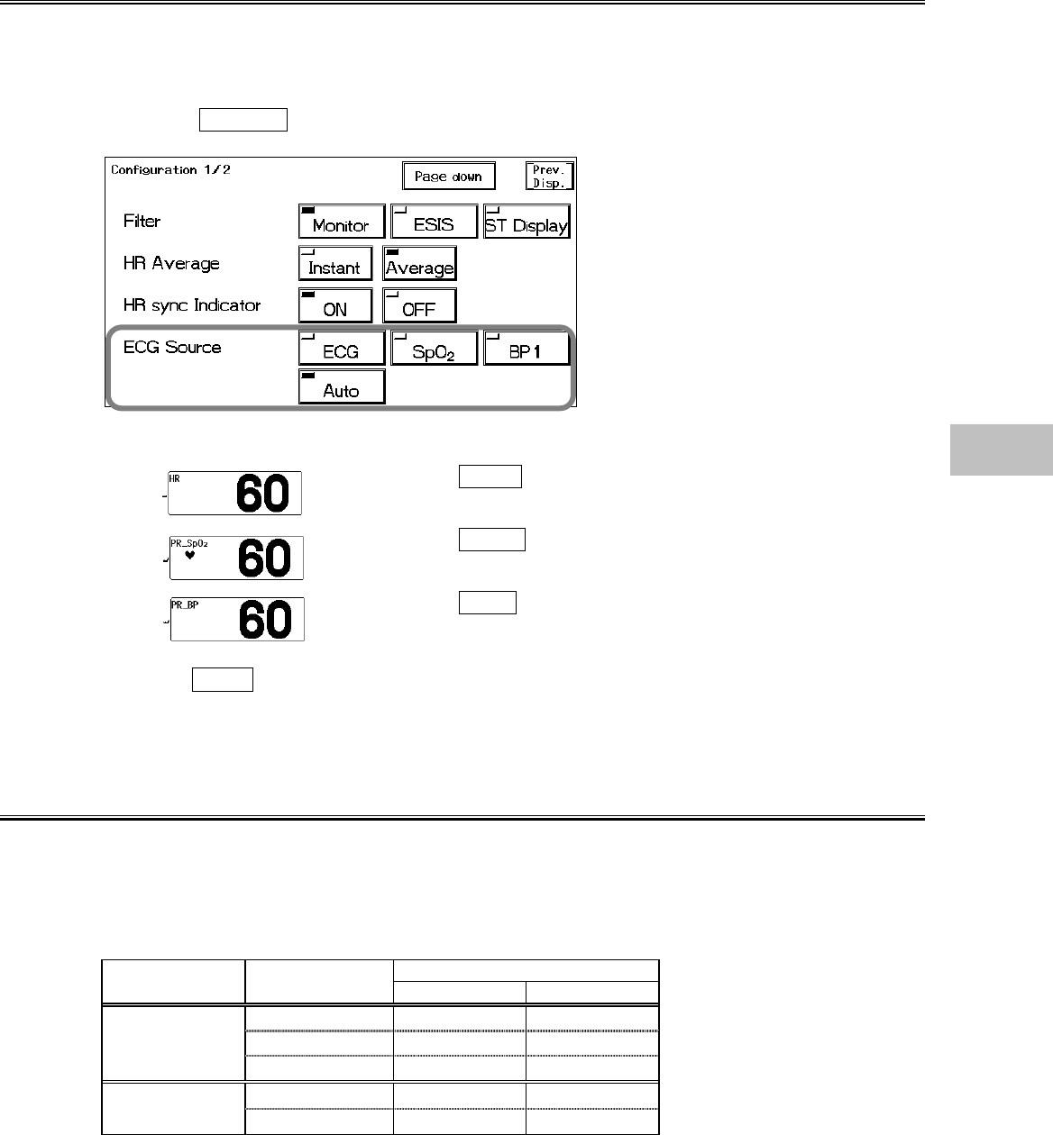
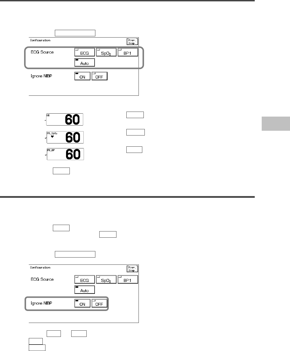
ECG Source
The ECG source to display on the home display can be selected.
The alarm will be generated based on this selection.
The tabular trend and graphic trend will be also based on this selection.
1. Press the Config. key to display the setup menu for selecting the ECG source.
2. Select a parameter.
Selecting ECG will measure the HR from ECG.
“HR” will be displayed inside the parameter key.
Selecting SpO2 will measure the PR from SpO2.
“PR_SpO2” will be displayed inside the parameter key.
Selecting BP1 will measure the PR from BP1.
“PR_BP” will be displayed inside the parameter key.
Selecting Auto will automatically set the measurable HR source in the priority of ECG>SpO2
>BP.
Automatic Lead Switching
By setting the Automatic Lead Switching ON, a new ECG lead will be automatically set when the
electrode comes off. When the lead off condition occurs, the “Check Electrodes” message will
be displayed and a new ECG lead will be automatically set if the Automatic Lead Switching is set
to ON.
Lead Switching
Auto Lead Selected
Type Electrode Off ECG1 ECG2
RA/RA+C Ⅲ Ⅲ
LA/LA+C Ⅱ Ⅱ5-electrode cable
CⅡaVR
RA Ⅲ Ⅲ
4-electrode cable LA Ⅱ Ⅱ
6
ECG
6−10
1. Press the Config. → Page Down keys to display the setup menu for setting the auto
lead switching.
2. Select ON or OFF .
OFF will not switch the lead when an electrode comes off.
ON will automatically switch to another lead when an electrode comes off.
Pacemaker Pulse
The artificial pace pulse can be displayed by superimposing on the ECG waveform. The artificial
pace pulse will be displayed in yellow.
Pacemaker Pulse Detection Algorithm
①
②
③①ECG Signal Input
Inputs ECG signal.
②Suspension of Pacemaker Pulse and QRS Detection
Signals with high frequency and large amplitude will be
detected as a pacemaker pulse. When a pacemaker
pulse is detected, QRS detection will be suspended for a
certain amount of time to prevent the pacemaker pulse
erroneously detected as QRS.
③Canceling Arrhythmia Detection
Arrhythmia detection will be cancelled to avoid detecting
the waveform succeeding the pacemaker pulse as an
abnormal beat.
CAUTION
Precautions about Pacemaker Pulse Detection
?
There are some cases when pacemaker pulse can not be detected
depending on the pacemaker type, pulse voltage, pulse width, electrode
lead type (unipolar, bipolar), or electrode placement which causes the
pacemaker pulse amplitude to decrease and disables pacemaker pulse
detection.
?
If signals similar to a pacemaker pulse are present, such as electric
blanket noise or excessive AC frequency noise, these may be
erroneously detected and displayed as a pacemaker pulse.
?
When the spontaneous QRS and pacemaker pulse overlaps (as in a
fusion beat), QRS detection will be suspended and the heart rate will be
reduced.
?
If a pacemaker pulse is continuously detected due to AC frequency
interference, QRS detection will be suspended and the heart rate will be
reduced. Also arrhythmia detection will not be possible.
6−11
1. Press the Config. → Page Down key to display the setup menu for pacemaker pulse
selection.
2. Select ON or OFF .
OFF will not display the pacemaker artificial pulse.
ON will display the pacemaker artificial pulse in a different color from the ECG waveform.
This will automatically set to ON when “Used” is selected for pacemaker use on the patient
admit / discharge menu.
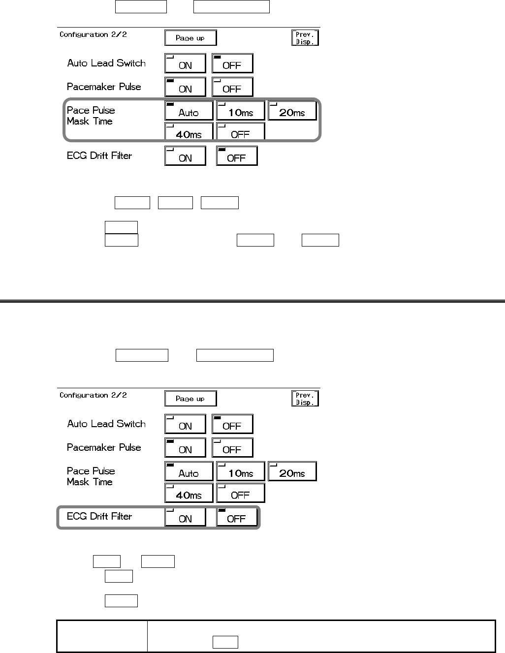
QRS Pace Mask
For patients using pacemakers, there are cases when the pacing waveform may not occur in spite
of the pacing stimulus. This condition is called “pacing failure”, or “failure to capture”. To avoid
detecting pacemaker pulses as a QRS complex when this occurs, the monitor has a function to
suspend QRS detection for a fixed amount of time starting from the detection of the pacing
stimulus. This function is called “pace mask”. But if the pacemaker does not detect the patient’s
spontaneous heartbeat (sensing failure), and the pacing stimulus is applied at the same timing as
QRS, this “pace mask” function may erroneously mask the QRS and cause the heart rate
measurement to decrease. To avoid this, QRS pace mask function can be turned off for correct
measurement of the heart rate. (default setting : ON)
Pacemaker Pulse Pacemaker Pulse
Pacing waveform caused
by pacemaker pulse No waveform in spite
of pacing stimulus.
Normal Pacing Pacing Failure Sensing Failure
Pacemaker pulse applied
at the same timing with
spontaneous heartbeat
WARNING
If the QRS pace mask function is turned OFF, a decrease in heart rate may
not generate HR or ASYSTOLE alarms due to erroneously detected QRS.
Turn this function OFF only if you are sure that pacing failure will not occur,
or when the patient can be constantly monitored.
6
ECG
6−12
1. Press the Config. → Page Down keys to display the second page of the
configuration menu.
2. Select the pace pulse mask time.
Select from 10ms , 20ms , 40ms depending on the pace spike amplitude or presence of
fusion beat.
Selecting OFF will set the mask time to 0ms.
Selecting Auto will switch between 20ms and 40ms depending on the pace spike
amplitude.
ECG Drift Filter
By setting the ECG drift filter ON, only the amplitude with frequency component under 1Hz will be
attenuated to prevent the ECG baseline drift.
1. Press the Config. → Page Down keys to display the second page of the
configuration menu.
3. Select ON or OFF for the ECG drift filter.
Selecting ON will set the ECG drift filter and controls the baseline drift.
When the ECG drift filter is set, the patient signal display will delay about 0.5 seconds.
Selecting OFF will not set the ECG drift filter.
NOTE When an electrosurgery-proof ECG relay cable is used, ECG drift filter can
not be set to ON .
6−13
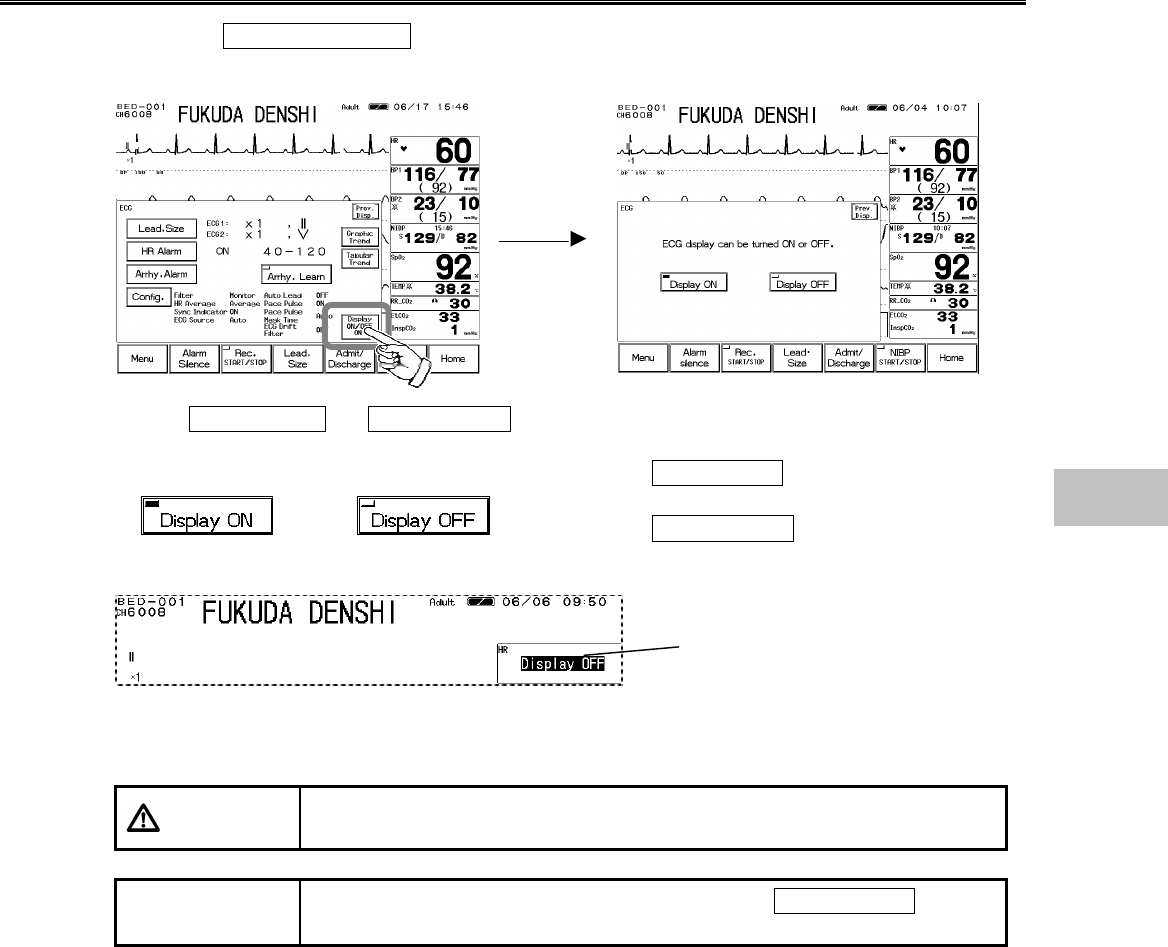
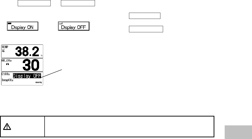
ON/OFF of Parameter Display
1. Press the Display ON/OFF key. The confirmation display for ON/OFF of ECG display
will appear.
2. Select Display ON or Display OFF .
Pressing the Display ON key will display the
waveform and numeric data.
Pressing the Display OFF key will not display the
waveform and numeric data.
When ECG electrodes are attached to the patient with the ECG display set to OFF, the ECG
waveform and numeric data will be automatically displayed after 30 seconds.
CAUTION When the waveform and numeric data display is set to OFF, the alarm
generation and tabular/graphic trend will be also set to OFF.
NOTE If ECG source is set to other than ECG, selecting Display OFF will
display PR_SpO2 or PR_BP for the HR parameter key.
The Display OFF message will be
displayed inside the parameter key.
6
ECG
6−14
− Respiration −
This menu allows setup for the impedance respiration measurement and CO2 respiration
measurement.
Size :Selects the waveform size to display impedance respiration.
RR Alarm :Selects ON/OFF of respiration rate alarm, and sets upper and lower alarm limits.
APNEA Alarm :Selects ON/OFF of apnea alarm and sets upper alarm limit.
Configuration :Sets the respiration monitoring configuration.
CAUTION
?
When the following relay cables are used, respiration can not be
measured.
?
Relay Cable CI‐700E_3 (Electrosurgery-proof, 3-electrode)
?
Relay Cable CI‐700E_4 (Electrosurgery-proof, 4-electrode)
?
Relay Cable CI‐700E_5 (Electrosurgery-proof, 5-electrode)
?
When a defibrillator is used during respiration monitoring, a large offset
voltage will be placed on the ECG electrodes, which may cause
interruption of monitoring for a few seconds.
?
When the following lead cables are used, respiration cannot be
measured.
?
Lead Cable #3382.0648.16 (Electrosurgery-proof, 3-electrode)
?
Lead Cable #3382.0661.16 (Electrosurgery-proof, 5-electrode)
Respiration Waveform Size
1. Press the Size key to display the size setup menu.
Select the waveform size and baseline position to display and record the impedance respiration
waveform.
2. Select the waveform size.
Select the size from ×1/4 , ×1/2 , ×1 , ×2 , ×4 .
3. Set the baseline position using the ? , ? keys.
Adjust the baseline position for 0Ω if the waveform is hard to see due to the waveform amplitude.
6−15
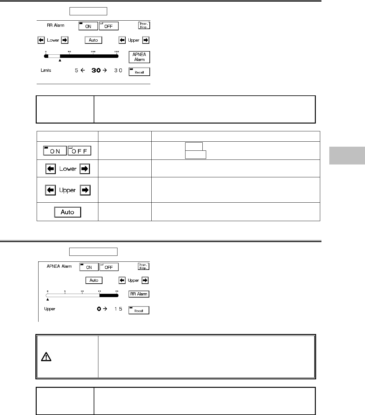
RR Alarm
1. Press the RR Alarm key to display alarm setup menu.
Set ON/OFF of RR alarm and upper and lower alarm
limit.
The alarm will be set common to RR measured from
impedance respiration waveform or RR measured from
CO2 waveform.
The adjustable increment for upper and lower limit
depends on the patient type.
Adult / Child :5bpm increment
Neonate :2bpm increment
NOTE If the alarm is based on the RR measured from CO2 waveform, RR alarm
will not generate unless 2 or more respiration is detected within 30 seconds
after power ON or after discharge.
Key Item Description
Individual Alarm Selecting ON will generate the RR alarm.
Selecting OFF will not generate the RR alarm.
Lower Alarm
Limit Sets the lower alarm limit (5∼145Bpm/5∼148Bpm).
Setting a value 5Bpm or below will turn OFF the alarm.
Upper Alarm
Limit
Sets the upper alarm limit (10∼150Bpm/4∼150Bpm).
Setting a value 150Bpm or above will turn OFF the
alarm.
Automatic
Setup Automatically sets the upper limit to +20Bpm, and the
lower limit to −20Bpm to the current value.
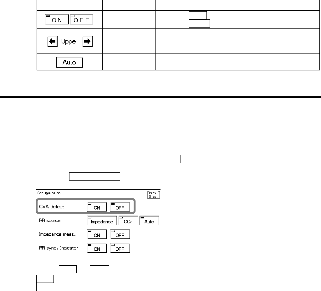
Apnea Alarm
1. Press the Apnea Alarm key to display the alarm setup menu.
Set ON/OFF of apnea alarm and upper limit of apnea
time.
Apnea will be set common to apnea time measured from
impedance respiration waveform or apnea time
measured from CO2 waveform.
The upper limit can be set in 1-second increment.
There is no lower limit.
WARNING
The purpose of this respiration alarm is to alert the user to evaluate for
the possible occurrence of apnea events by identifying the absence of
respiration. It is not intended to be classified as an “Apnea Monitor” and
will not identify the condition creating the possible event. (Central,
Obstructive or Mixed.)
NOTE If the alarm is based on the apnea time measured from CO2 waveform,
apnea alarm will not generate unless 2 or more respiration is detected
within 30 seconds after power ON or after discharge.
6
Respiration
6−16
Key Item Description
Individual Setup Selecting ON will generate the apnea alarm.
Selecting OFF will not generate the apnea alarm.
Upper Alarm
Limit
Sets the upper alarm limit (5∼20sec.).
Setting a value equal to or above 20sec. will turn OFF
the alarm.
Automatic
Setup Sets the apnea alarm value set for the currently
selected alarm mode.
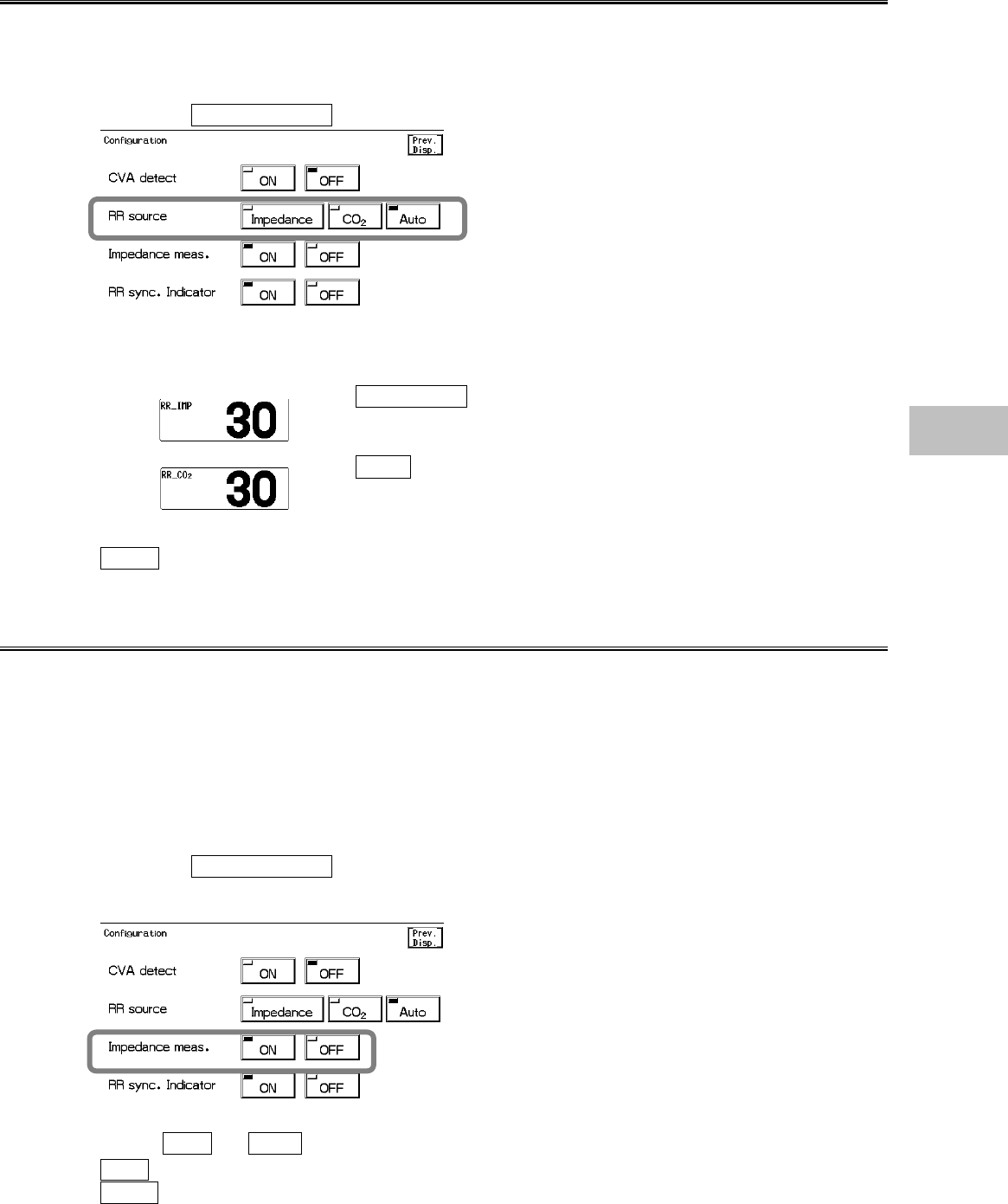
CVA Detection
When the amplitude of the respiration waveform decreases due to causes such as respiratory
pause, the ECG waveform may be superimposed on to the respiration waveform, making the RR
equal to the HR. This condition is called CVA (Cardio-Vascular Artifact), and is detected using
the CVA detection function.
If the ECG waveform is superimposed on to the respiration waveform, with HR (RR) 30bpm, for 20
seconds or over (10 seconds or over for neonates) and the CVA detection function set to ON, the
“CVA detected” message will be displayed, and an alarm sound will be generated.
This function will be effective when Impedance is set as the RR source.
1. Press the Configuration key to display the setup menu for setting the CVA detection.
2. Select ON or OFF .
ON will generate an alarm and display a message when CVA is detected.
OFF will not perform CVA detection.
6−17
Respiration Source
The parameter to measure respiration rate and apnea time can be selected from impedance, CO2,
or automatic. RR and apnea alarm will be generated according to the selected parameter.
These will be also stored as graphic trend or tabular trend.
1. Press the Configuration key to display configuration menu for RR source selection.
2. Select the parameter.
Impedance will measure respiration rate from impedance
respiration curve. The numeric value will be indicated as
“RR_IMP” in the respiration parameter key.
CO2 will measure respiration rate from CO2 waveform. The
numeric value will be indicated as “RR_CO2” in the respiration
parameter key.
Auto will automatically select the parameter to measure the respiration rate with the priority
order of CO2>impedance.
Impedance Respiration Measurement
The respiration measurement using the impedance method conducts high-frequency and weak
current between the ECG electrodes attached to the patient, and measures the potential
difference between the electrodes caused by thoracic movement using the synchronous
rectification system. For a patient using the adaptive (minute ventilation) pacemaker, the
pacemaker measurement signal and the high-frequency current of this equipment interferes with
each other which causes incorrect respiration measurement.
If the patient is using an adaptive (minute ventilation) pacemaker, set the impedance respiration
measurement OFF.
1. Press the Configuration key to display the setup menu to set the impedance respiration
measurement.
2. Select ON or OFF .
ON will perform standard impedance respiration measurement.
OFF will stop the impedance respiration measurement and will not display the impedance
respiration waveform and RR. A high frequency electric discharge which is a measurement
signal will be also ceased.
6
Respiration

6−18
RR Synchronization Mark
The RR mark synchronized to impedance respiration or CO2 waveform will be displayed inside the
parameter key.
RR Mark
1. Press the Configuration key to display the setup menu for setting the RR synchronized
Mark.
2. Select ON or OFF .
OFF will not display the synchronization mark.
ON will display the synchronization mark.
6−19
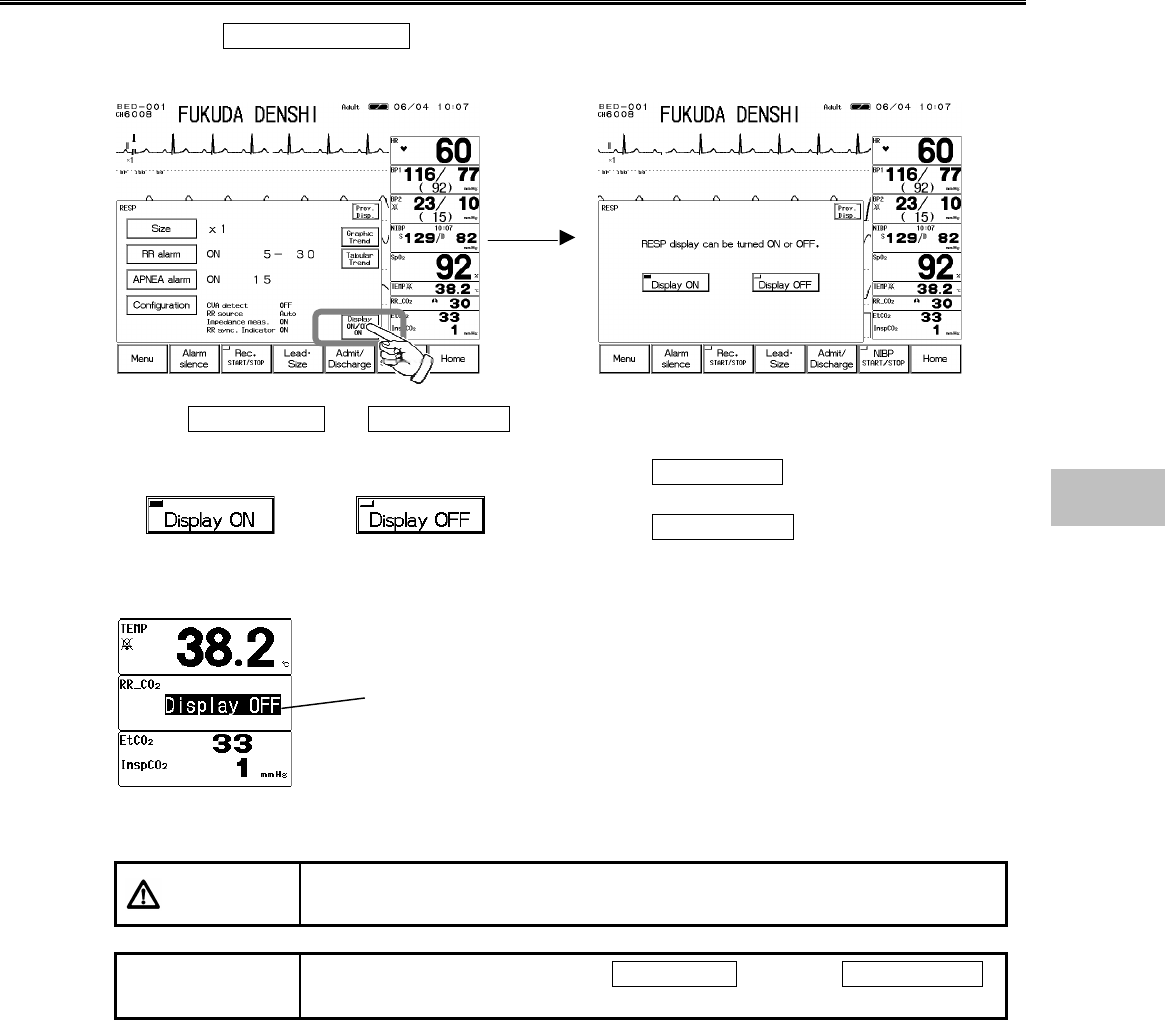
ON/OFF of Parameter Display
1. Press the Display ON/OFF key. The confirmation display for ON/OFF of RESP display
will appear.
2. Select Display ON or Display OFF .
Pressing the Display ON key will display the
waveform and numeric data.
Pressing the Display OFF key will not display the
waveform and numeric data.
When ECG electrodes are attached to the patient with the respiration display set to OFF, the
respiration waveform and numeric data will be automatically displayed after 30 seconds.
CAUTION When waveform and numeric data display is set to OFF, the alarm
generation and tabular/graphic trend will be also set to OFF.
NOTE If RR source is set to other than Impedance , selecting Display OFF
will display CO2_RR for the RESP parameter key.
The Display OFF message will be
displayed inside the parameter key.
6
Respiration
6−20
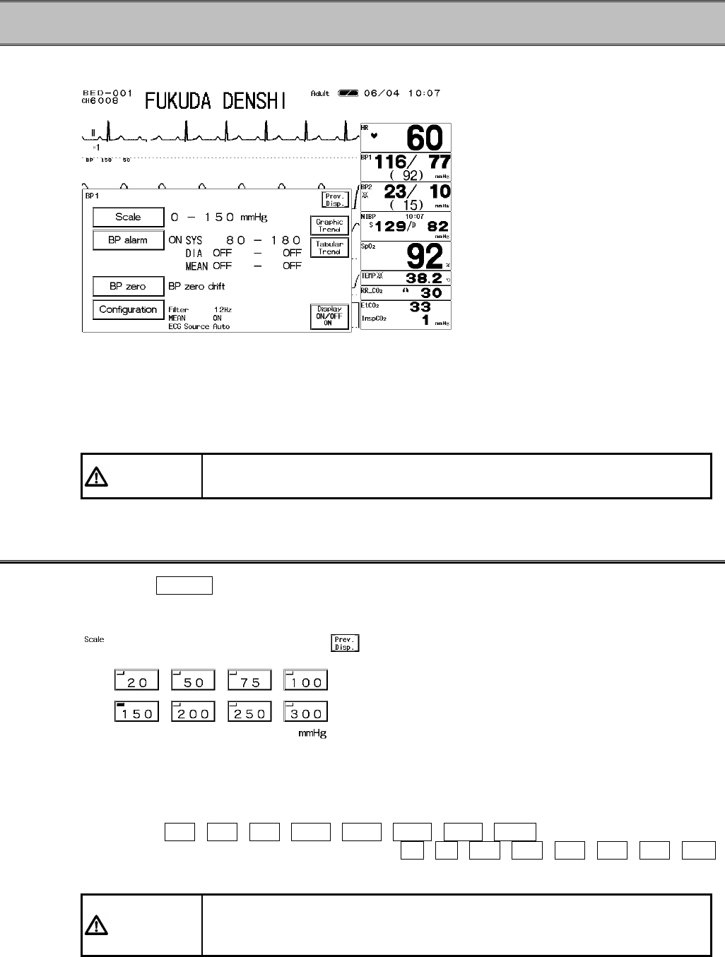
− Invasive Blood Pressure (BP1, BP2)−
This menu allows setup of the measurement condition for BP1, BP2.
Scale :Selects the scale for BP waveform display.
BP Alarm :Sets the upper and lower alarm limit of systolic, diastolic, mean blood pressure and
ON/OFF of the alarm.
BP Zero :Performs zero balance.
Configuration:Sets the BP monitoring condition.
CAUTION When the main power is turned ON, the BP value will not be displayed until
zero balance is performed. Make sure to perform the zero balance.
BP Scale (BP1, BP2)
1. Press the Scale key to display the BP scale setup menu.
Select the full scale for displaying and recording.
2. Select the scale.
Select from 20 , 50 , 75 , 100 , 150 , 200 , 250 , 300 (mmHg).
When the measurement unit is kPa, select from 4 , 8 , 12 , 16 , 20 , 24 , 32 , 40
(kPa).
CAUTION For telemetry transmission, BP waveform with a scale above the
programmed scale can not be properly transmitted. Set the BP waveform
below the programmed scale.
6−21
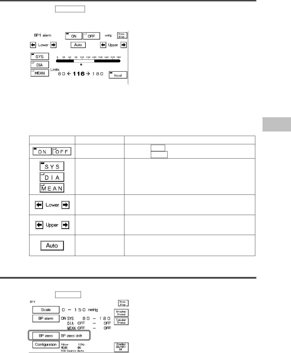
BP Alarm (BP1, BP2)
1.Press the BP Alarm key to display the alarm setup menu.
Select ON/OFF of BP alarm and set the upper and lower alarm limit for systolic (SYS), diastolic
(DIA), and mean (MEAN) BP.
The alarm value is to be set for each measurement unit. (mmHg / kPa)
The adjustable increment for upper and lower limit changes from 50mmHg / 7kPa.
mmHg :0∼50mmHg / 2mmHg increment
55∼300mmHg / 5mmHg increment
kPa :0∼7kPa / 0.2kPa increment
7.5∼40.0kPa / 0.5kPa increment
Key Item Description
Individual Alarm Selecting ON will generate BP alarm.
Selecting OFF will not generate BP alarm.
Select from SYS (systolic BP), DIA (diastolic BP),
MEAN (mean BP).
Lower Alarm Limit Sets the lower alarm limit (0∼295mmHg/0∼39.5kPa).
Setting a value equal to or below 0mmHg/0kPa will
turn OFF the alarm.
Upper Alarm Limit Set the upper limit (2∼300 mmHg/0.2∼40.0kPa).
Setting a value equal to or above 300 mmHg/40.0kPa
will turn OFF the alarm.
Automatic Setup Automatically sets the upper limit to +40mmHg/+
5.5kPa, and the lower limit to −20mmHg/−2.5kPa to
the current value.
Zero Balance of Pressure Lines (BP1, BP2)
1. Open the three-way cock of the pressure transducer to air.
2. Press the BP zero key.
6
BP
6−22
Verify the BP waveform is positioned at zero, and “0” is displayed for the BP value. A message,
“BP zero complete” will be displayed when the procedure is complete. A message, “BP zero
failed” will be displayed when the process fails. The three-way cock may not be opened to air,
artifact is present, or the transducer may be defective. Check the cause and try the zero balance
procedure again.
A message, “BP zero drift” will be displayed when the interface cable is not connected. Check if
the cable is firmly connected.
3. Close the three-way cock when the zero balance is complete.
CAUTION Each time the blood pressure transducer or tubing is replaced, the zero
balance procedure is required to ensure accurate measurements.
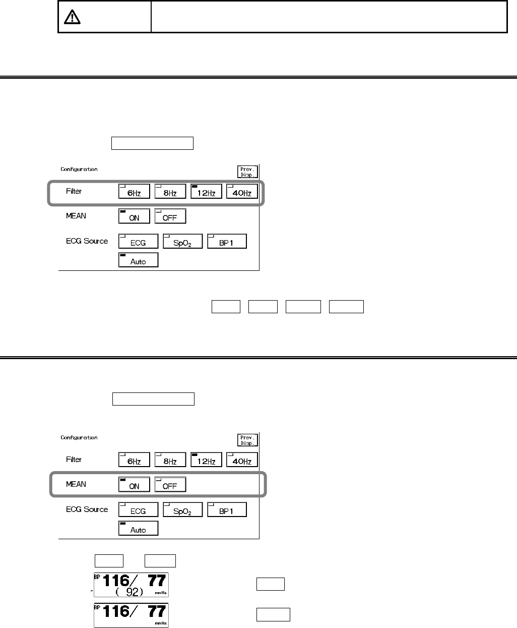
Filter Selection (BP1, BP2)
An artifact may interfere on the BP waveform depending on the combination of BP measurement
circuit.
Select an appropriate filter from the low-pass filter of 6Hz, 8Hz, 12Hz, 40Hz.
1. Press the Configuration key to display the setup menu for selecting a filter.
2. Select the filter.
Select an appropriate filter from 6Hz , 8Hz , 12Hz , 40Hz .
Mean BP Display (BP1, BP2)
The ON/OFF of mean BP display can be selected.
1. Press the Configuration key to display the setup menu for selecting ON/OFF of mean
BP display.
2. Select ON or OFF .
Selecting ON will display the mean BP.
Selecting OFF will not display the mean BP.
6−23
CAUTION If the mean BP display is set to OFF, the mean BP alarm will not be
generated. Also, the mean BP will not be displayed on the tabular trend.
Be cautious when setting the mean BP display OFF.
ECG Source (BP1)
The HR/PR source to display on the home display can be selected.
The alarm will be generated based on this selection.
The graphic trend and tabular trend will be also stored based on this selection.
BP2 can not be set as ECG source.
1. Press the Configuration key to display the setup menu to set the ECG source.
2. Select a parameter.
Selecting ECG will measure the HR from ECG.
“HR” will be displayed inside the parameter key.
Selecting SpO2 will measure the PR from SpO2.
“PR_SpO2” will be displayed inside the parameter key.
Selecting BP1 will measure the PR from BP1.
“PR_BP” will be displayed inside the parameter key.
Selecting Auto will automatically set the measurable HR source in the priority of ECG>SpO2
>BP1.
6
BP
6−24
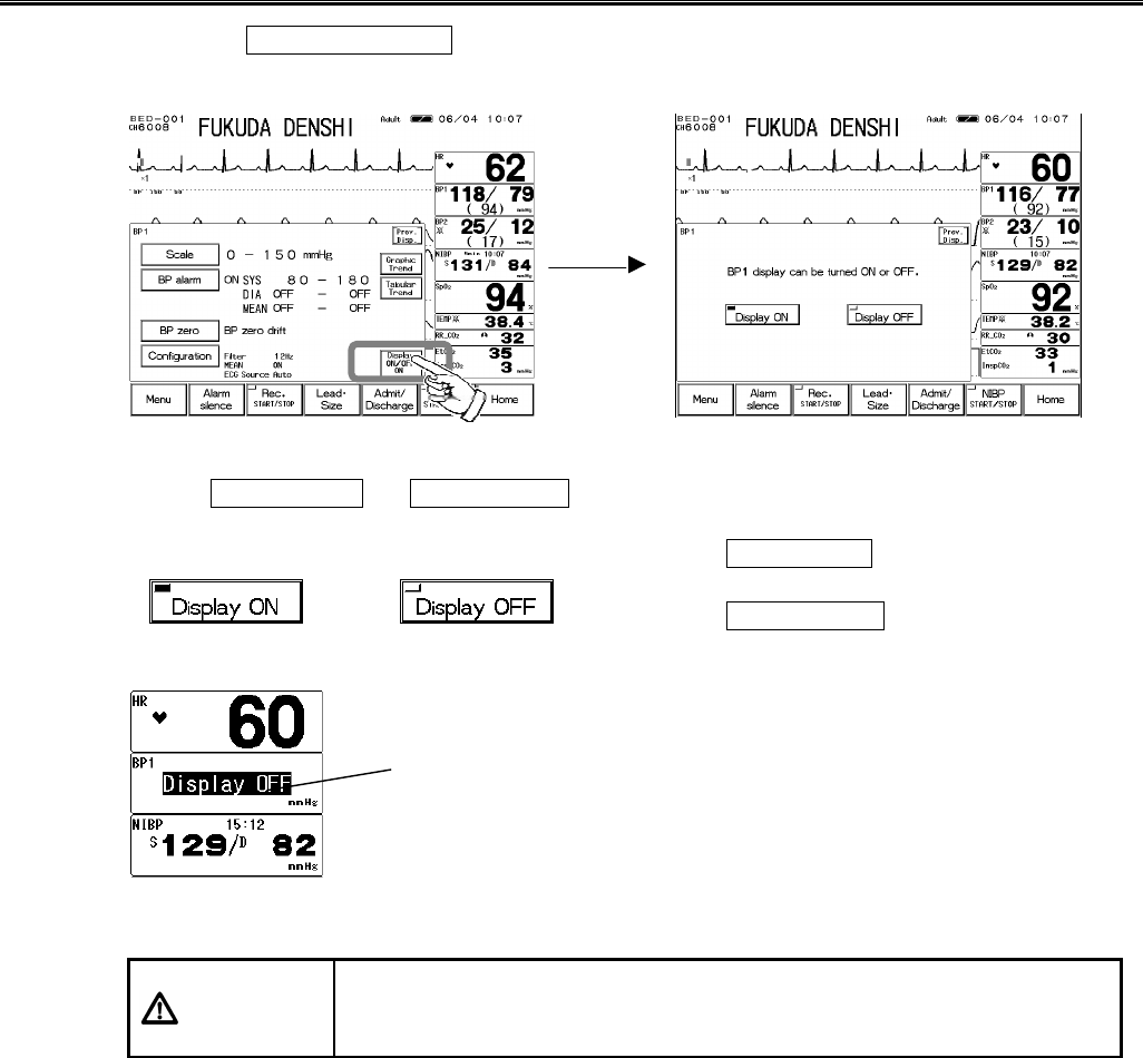
ON/OFF of Parameter Display
1. Press the Display ON/OFF key. The confirmation display for ON/OFF of BP display will
appear.
2. Select Display ON or Display OFF .
Pressing the Display ON key will display the
waveform and numeric data.
Pressing the Display OFF key will not display the
waveform and numeric data.
CAUTION
?
When waveform and numeric data display is set to OFF, the alarm
generation and tabular/graphic trend will be also set to OFF.
?
If BP is set as ECG source, the pulse rate will also not be displayed.
The Display OFF message will be
displayed inside the parameter key.
6−25
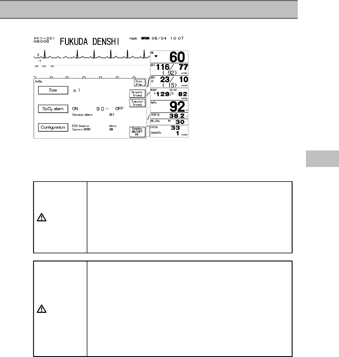
− SpO2 −
This menu allows setup of the measurement condition for the SpO2.
Size :Sets the waveform size for SpO2 waveform display.
SpO2 Alarm :Sets ON/OFF of alarm, upper and lower alarm limit, and SEC alarm.
Configuration:Sets the SpO2 monitoring configuration.
CAUTION
Take the following precautions when monitoring over long periods of time.
?
To avoid skin rash or low-temperature burn, it is recommended to
change the measurement position several times a day.
Be especially careful when continuously using on neonates, infants, or
patients with peripheral circulatory disturbance.
?
Direct sunlight to the sensor area can cause a measurement error.
Place a black or dark cloth over the sensor in these environments.
When not measuring, unplug the relay cable and sensor from the SpO2
connector. Otherwise, the outside light may affect to falsely display
measurements.
CAUTION
?
The DS-100A is intended for use on finger of adults weighing over 40
kg (approximate). Do not use them on children or neonates. Also do
not apply them on the thumb or foot.
?
The light-emitting part of the sensor should be over the root of the
fingernail. Do not insert the finger too far into the sensor as it may hurt
the patient.
?
The DS-100A is not designed for long term use. Remove the sensor
every 4 hours. If any inhibition is detected in tissue blood flow, replace
it or move the sensor to another finger.
?
Measuring on a limb with NIBP cuff, arterial catheter, or intracatheter
may result in incorrect measurement.
?
Do not secure the adhesive tape too tight as it may obstruct the blood
flow.
6
SpO2
6−26
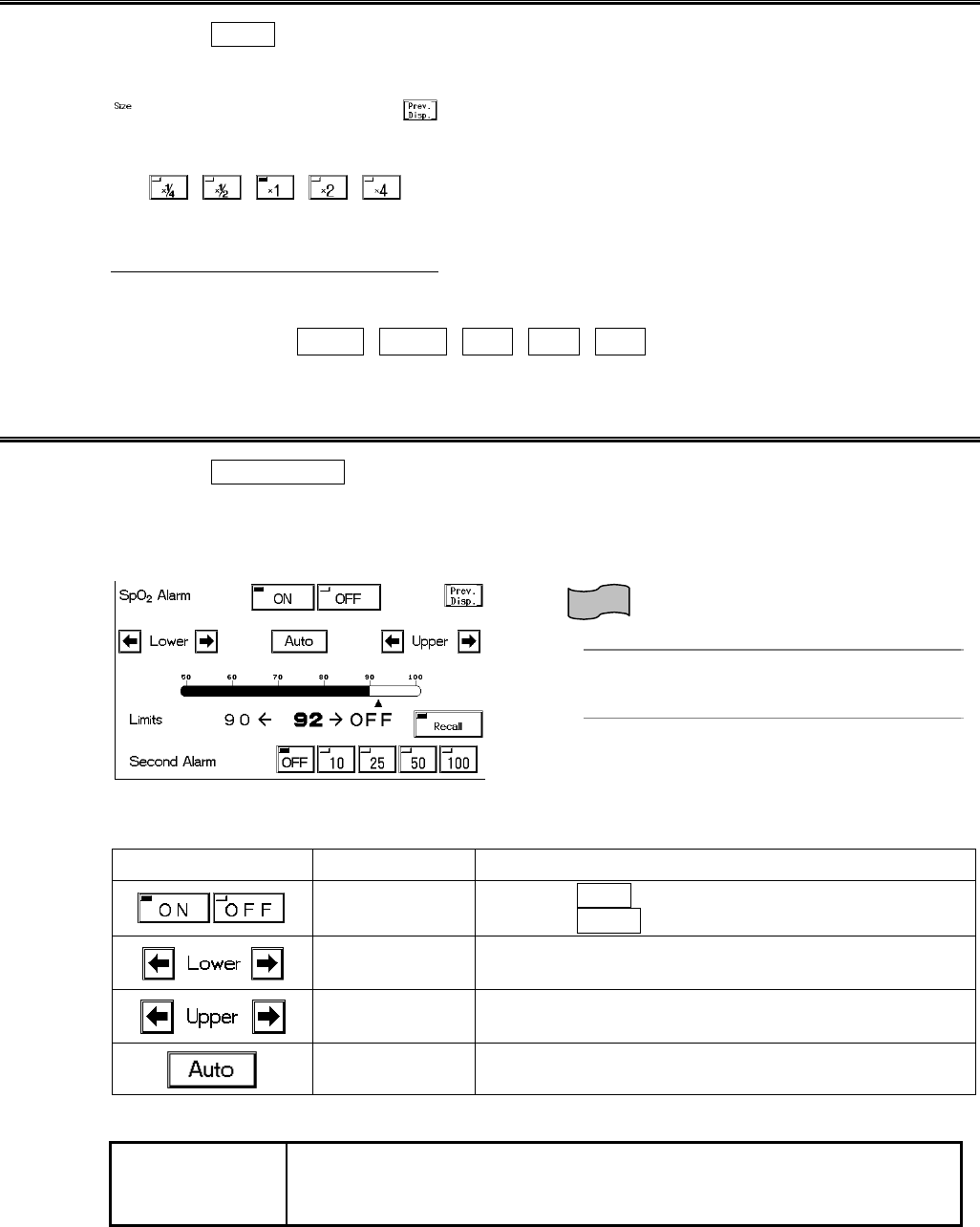
SpO2 Waveform Size
1. Press the Size key to display the SpO2 waveform size setup menu.
Select the waveform size for displaying and recording.
2. Select the waveform size.
Select the size from ×1/4 , ×1/2 , ×1 , ×2 , ×4 .
SpO2 Alarm
1. Press the SpO2 Alarm key to display the alarm setup menu.
Select ON/OFF of SpO2 alarm, and set the upper and lower alarm limit.
Also, when the SpO2 value is unstable around the lower alarm limit, the frequently generated
alarm can be corrected by setting the SEC (second) alarm function.
Reference
Refer to ”4. Monitoring Setup SpO2 SEC
Alarm Setup” for details of SEC alarm setup
procedure.
The upper and lower limits can be set in 1% increment.
Key Item Description
Individual Alarm Selecting ON will generate the SpO2 alarm.
Selecting OFF will not generate the SpO2 alarm.
Lower Alarm
Limit Sets the lower alarm limit (50∼99%).
Setting a value 50% or below will turn OFF the alarm.
Upper Alarm
Limit Sets the upper alarm limit (52∼100%).
Setting a value 100% or above will turn OFF the alarm.
Automatic
Setup Automatically sets the upper limit to OFF, and the
lower limit to 95% to the current value.
NOTE Whether to use the SEC (second) alarm function and its threshold
selection should be based on the patient’s clinical indication portent and
medical evaluation.
6−27
ECG Source
The HR/PR source to display on the home display can be selected.
The alarm will be generated based on this selection.
The graphic trend and tabular trend will be also stored based on this selection.
1. Press the Configuration key to display the setup menu to set the ECG source.
2. Select a parameter.
Selecting ECG will measure the HR from ECG.
“HR” will be displayed inside the parameter key.
Selecting SpO2 will measure the PR from SpO2.
“PR_SpO2” will be displayed inside the parameter key.
Selecting BP1 will measure the PR from BP1.
“PR_BP” will be displayed inside the parameter key.
Selecting Auto will automatically set the measurable ECG source in the priority of ECG>SpO2
>BP1.
SpO2 Alarm during NIBP Measurement (Ignore NIBP)
This setup is to be made when the SpO2 sensor and NIBP cuff is placed on the same limb for
measurement.
During the NIBP measurement, the cuff inflation restricts the blood flow which disables the correct
detection of the SpO2 value and PR, and may generate an improper alarm.
Selecting OFF will not generate the alarm until the NIBP measurement is complete. Similarly,
when the HR source is set as SpO2 , the PR alarm will not be generated during NIBP
measurement.
1. Press the Configuration key to display the setup menu for setting “Ignore NIBP”.
2. Select ON or OFF .
ON will generate the alarm during NIBP measurement.
OFF will not generate the SpO2/PR alarm during NIBP measurement.
6
SpO2
6−28
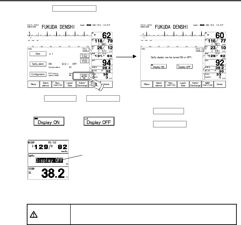
ON/OFF of Parameter Display
1. Press the Display ON/OFF key. The confirmation display for ON/OFF of SpO2 display
will appear.
2. Select Display ON or Display OFF .
Pressing the Display ON key will display the
waveform and numeric data.
Pressing the Display OFF key will not display the
waveform and numeric data.
When SpO2 sensor is attached to the patient with the SpO2 display set to OFF, and SpO2 can be
measured for 30 seconds, the SpO2 waveform and numeric data will be automatically displayed.
CAUTION
?
When the waveform and numeric data display is set to OFF, the alarm
generation and tabular/graphic trend will be also set to OFF.
?
If SpO2 is set as ECG source, the pulse rate will also not be displayed.
The Display OFF message will be
displayed inside the parameter key.
6−29
− Non-Invasive Blood Pressure −
This menu allows the setup of NIBP monitoring condition.
Auto Mode :Sets the automatic interval measurement and starts the 1-minute interval
measurement and Quick SYS measurement.
NIBP Alarm :Sets the ON/OFF of NIBP alarm and upper / lower limit of systolic, diastolic, and
mean BP.
Configuration :Sets the NIBP monitoring configuration.
CAUTION
For the following situation, measurements will be terminated.
?
When the measurement time has exceeded 120 seconds for adult, 90
seconds for child, 60 seconds for neonate.
?
When the inflation value has exceeded 300mmHg for adult, 200mmHg
for child, 150mmHg for neonate.
CAUTION If used with the incorrect patient type, it will not only cause erroneous
measurement, but the inflating level for the adult may be applied to child or
neonate causing a dangerous situation to the patient.
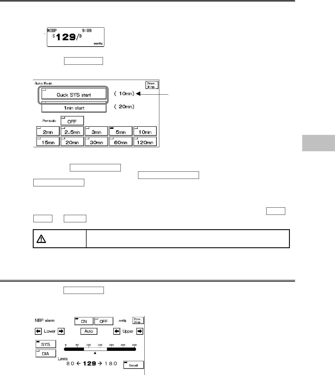
NIBP Automatic Measurement
Non-invasive blood pressure can be measured automatically at selected time intervals. If Quick
SYS measurement is performed during the NIBP automatic measurement, the automatic
measurement will automatically resume when Quick SYS measurement completes.
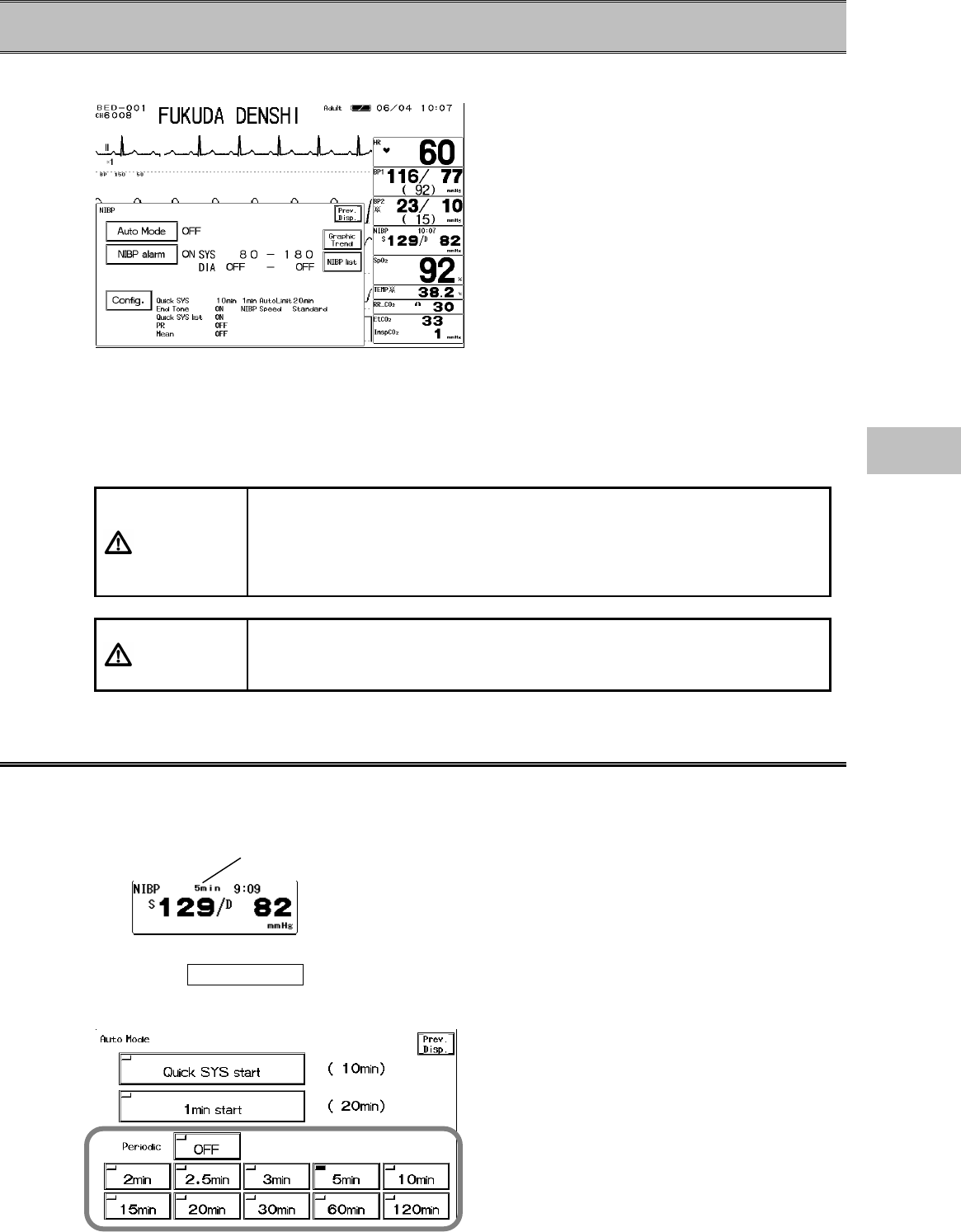
When NIBP automatic measurement is set, the set interval time
will be displayed inside the parameter key.
1. Press the Auto Mode key to display the measurement interval setup menu for the
automatic measurement.
Currently selected time interval
6
NIBP
6−30
2. Select an interval time.
Select from 2 min / 2.5 min / 3 min / 5 min / 10 min / 15 min / 20 min /
30 min / 60 min / 120 min .
Select OFF if not performing the interval measurement.
The measurement time will be the integral multiple of the selected interval time beginning with 0
minute.
Ex.)If the present time is 13:14, the measurement time will be as follows for each interval time.
2 min. :13:16, 13:18, 13:20, ...
2.5 min. :13:15, 13:17:30, 13:20, ...
3 min. :13:15, 13:18, 13:21, ...
5 min. :13:15, 13:20, 13:25, ...
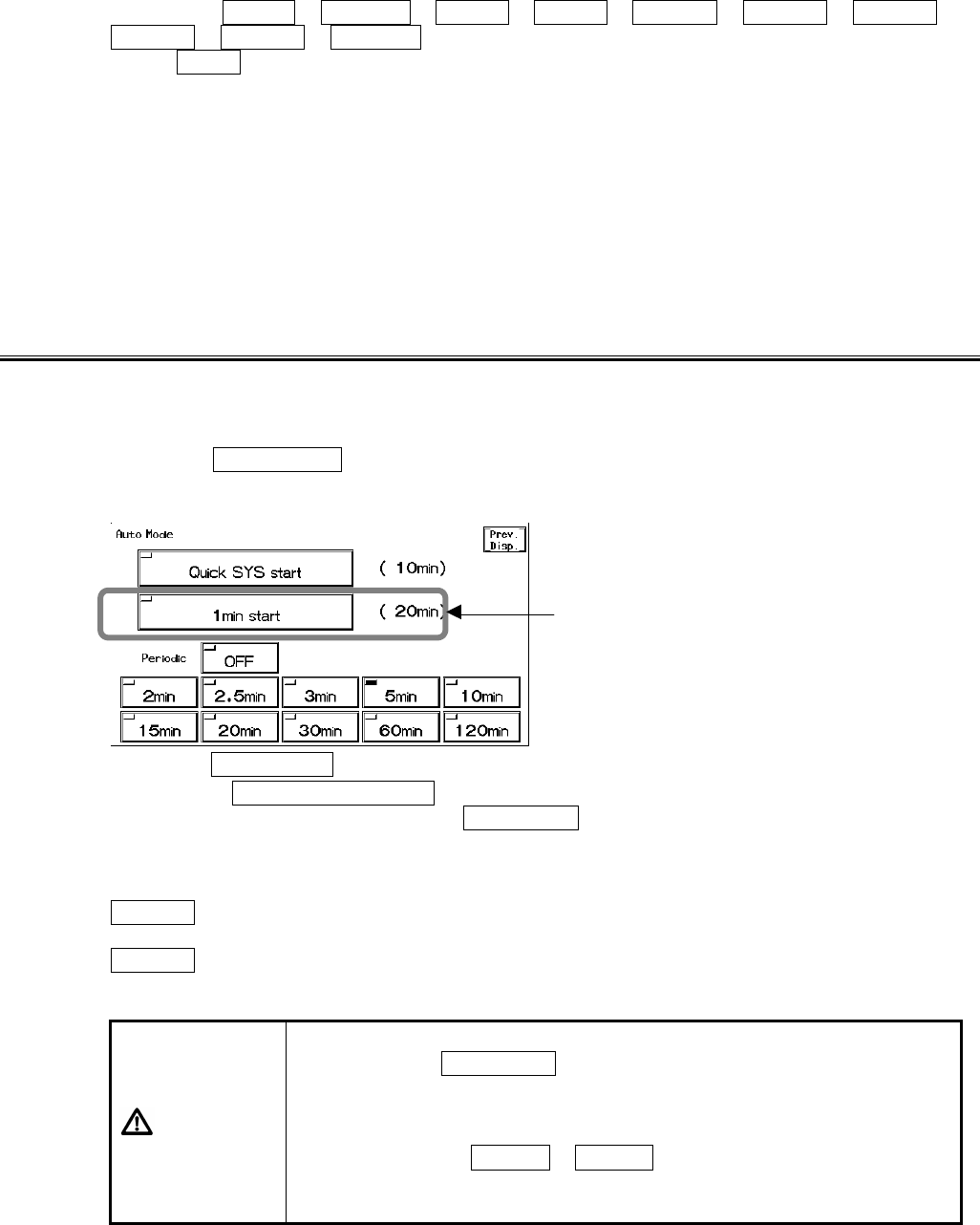
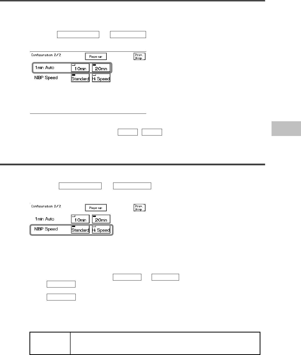
NIBP 1-Minute Interval Measurement
The 1-minute interval measurement will automatically stop after 10 minutes or 20 minutes and
returns to the previous interval mode setup.
1. Press the Auto Mode key to display the measurement interval setup menu to start the
1-minute interval measurement.
2. Press the 1min Start key to start the 1-minute interval measurement.
Pressing the NIBP START/STOP key will not stop the 1-minute interval measurement.
To cancel the measurement, press the 1min Start key again.
The measurement duration of 1-minute interval measurement can be selected on the “1min Auto”
of the NIBP configuration menu.
10min. will automatically stop the 1-minute interval measurement after 10 minutes and returns
to the previous interval mode setup.
20min. will automatically stop the 1-minute interval measurement after 20 minutes and returns
to the previous interval mode setup.
CAUTION
?
The 1-minute interval measurement will always start from 00 second.
Pressing the 1min Start key will start the measurement from the
next 00 second.
?
The 1-minute interval measurement will automatically stop after 10
minutes or 20 minutes and returns to the previous interval mode setup.
The selection of 10min / 20min can be made on the NIBP
configuration menu. (Refer to “1-Minute Measurement Duration” of
this section”
Measurement Duration
6−31
Quick SYS Start
The NIBP measurement can be continuously performed for 3 min. / 5 min. / 10 min.
If any abnormality on the cuff hose, etc. is found during the Quick SYS, the continuous
measurement will be ceased.
Only the systolic blood pressure will be measured and displayed.
1. Press the Auto Mode key to display the measurement interval setup menu to start the
Quick SYS.
2. Start the Quick SYS.
Pressing the Quick SYS Start key will start the continuous measurement.
To cease the measurement, press the NIBP START/STOP key, or press again the
Quick SYS Start key.
The duration of continuous measurement can be selected on the “Quick SYS” of the NIBP
configuration menu.
The continuous measurement will automatically cease after the selected duration from 3min ,
5min , or 10min .
CAUTION The alarm function will be ineffective for the BP value measured by Quick
SYS regardless of the ON/OFF selection of NIBP alarm.
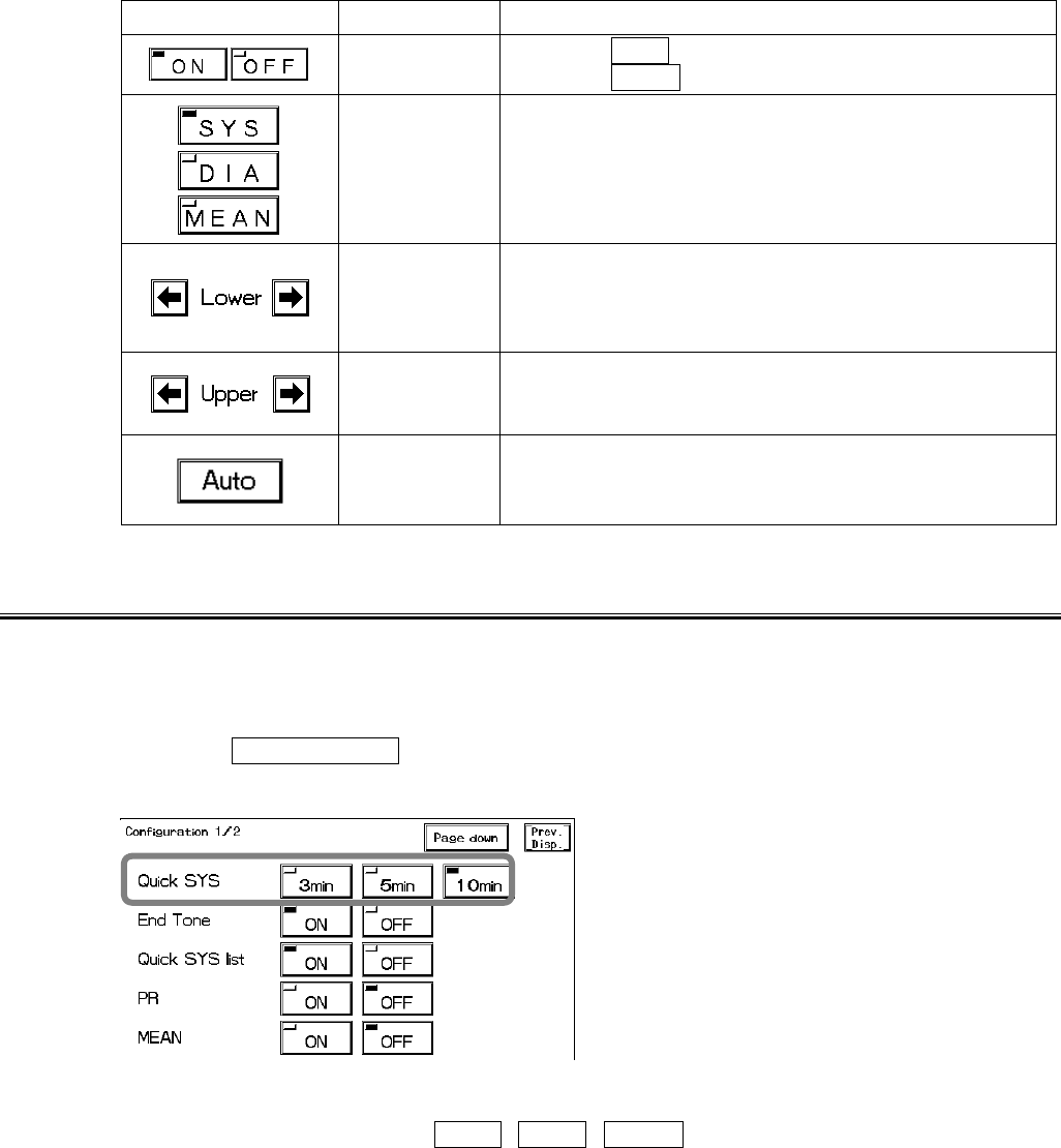
NIBP Alarm
1. Press the NIBP Alarm key to display the alarm setup menu.
Set ON/OFF of NIBP alarm, upper and lower alarm limits of systolic (SYS), diastolic (DIA), mean
(MEAN) NIBP.
Set the alarm value for each measurement unit (mmHg / kPa).
The upper and lower limit can be set in 5mmHg / 0.5kPa increment.
Measurement Duration
6
NIBP
6−32
Key Item Description
Individual
Alarm Selecting ON will generate the NIBP alarm.
Selecting OFF will not generate the NIBP alarm.
Select from SYS (systolic BP), DIA (diastolic BP), or
MEAN (mean BP)
Lower Alarm
Limit
Sets the lower alarm limit (10∼295mmHg/1.5∼
39.5kPa).
Setting a value 10mmHg/1.5kPa or below will turn OFF
the alarm.
Upper Alarm
Limit
Sets the upper limit (15∼300mmHg /2.0∼40.0kPa).
Setting a value 300bpm/40.0kPa or above will turn OFF
the alarm.
Automatic
Setup
Automatically sets the upper limit to +40mmHg/+
5.5kPa to the current value, and the lower limit to −
20mmHg/−2.5kPa to the current value.
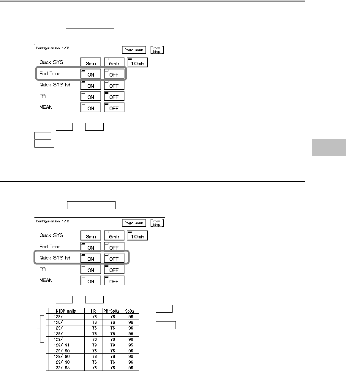
Quick SYS Measurement Duration
The duration of Quick SYS can be selected from 3 min., 5 min., or 10 min.
The long duration of continuous measurement may congest the blood stream of the measured
location. Set the duration according to the patient condition.
1. Press the Configuration key to display the NIBP configuration menu to set the Quick
SYS.
2. Select the measurement duration.
Select an appropriate time from 3min , 5min , 10min .
Quick SYS will automatically cease after the selected duration.
6−33
End of Measurement Tone
By selecting ON for the “End Tone”, a tone will be generated when the NIBP measurement
completes.
1. Press the Configuration key to display the NIBP configuration menu to set ON/OFF for
the End Tone.
2. Select ON or OFF .
ON will generate a tone when the measurement completes.
OFF will not generate a tone when the measurement completes.
Quick SYS List
The systolic blood pressure measured by Quick SYS can be included in the NIBP list.
1. Press the Configuration key to display the NIBP configuration menu for setting the
Quick SYS List.
2. Select ON or OFF .
ON will include the systolic blood pressure value
to NIBP list.
OFF will not include the systolic blood pressure
value to NIBP list.
Quick
SYS
6
NIBP
6−34
PR Display
The measured pulse rate can be displayed. This selection is for display only, and alarm function
and tabular trend function will be ineffective.
1. Press the Configuration key to display the NIBP configuration menu for setting the PR
display.
2. Select ON or OFF .
Pulse Rate
Selecting ON will display the pulse rate.
Selecting OFF will not display the pulse rate.
Mean BP Display
The ON/OFF of mean BP display can be selected.
1. Press the Configuration key to display the NIBP configuration menu for setting the
mean BP display.
2. Select ON or OFF .
ON will display the mean BP.
OFF will not display the mean BP.
6−35
1-Minute Measurement Duration
The duration for 1-minute measurement can be selected from 10 minutes or 20 minutes.
When the previous measurement is prolonged due to patient motion, etc, the cuff pressure release
time until the next measurement will be shortened, and the measured location may congest. Be
cautious when performing long duration of continuous measurement.
1. Press the Configuration → Page Down keys to display the NIBP configuration menu
for setting the 1-minute measurement duration.
2. Select the measurement duration.
Select an appropriate duration from 10min , 20min .
The 1-minute measurement will automatically cease after the selected duration.
NIBP Speed
The NIBP cuff inflation speed can be selected from standard or high speed.
1. Press the Configuration → Page Down keys to display the second page of the
configuration menu.
2. Select the NIBP speed.
Select an appropriate speed from Standard or Hi Speed .
When Standard is selected, it will take about 10 seconds to inflate to 300mmHg with 500cc
tank connected.
When Hi Speed is selected, it will take about 6 seconds to inflate to 300mmHg with 500cc tank
connected. (for adult)
When an adult cuff is wrapped around an arm with a space allowing one finger fitting in between
the cuff and arm, the speed to inflate to 190mmHg is within 11 seconds for normal speed, and
within 7 seconds for high speed.
NOTE The NIBP speed setup is effective only when adult or child is selected for
patient type. The NIBP speed for neonate will be fixed in spite of the speed
selection.
6
NIBP
6−36
− Temperature −
This menu allows the setup of the temperature monitoring condition.
TEMP Alarm :Sets ON/OFF of temperature alarm, and upper and lower alarm limits.
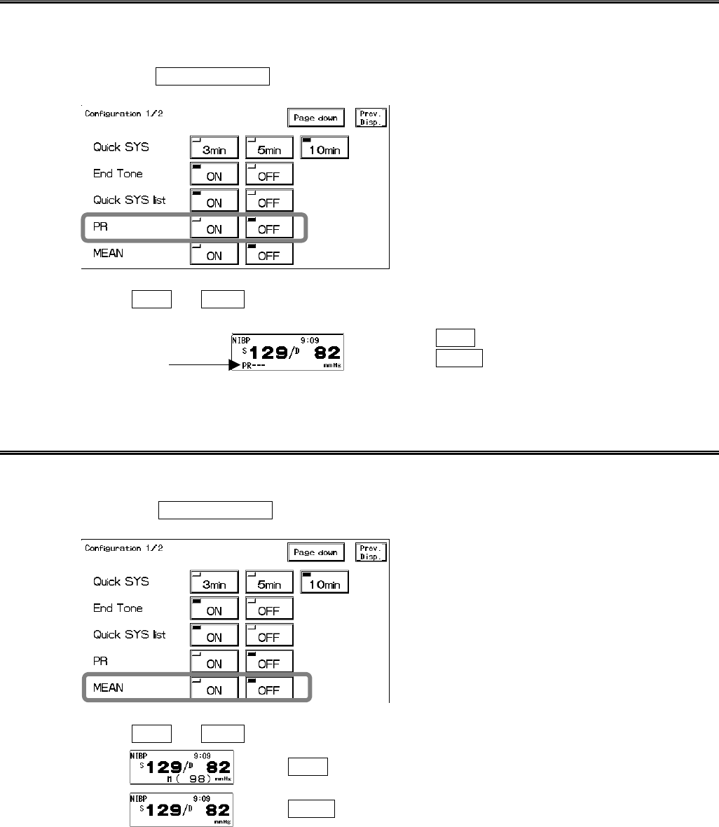
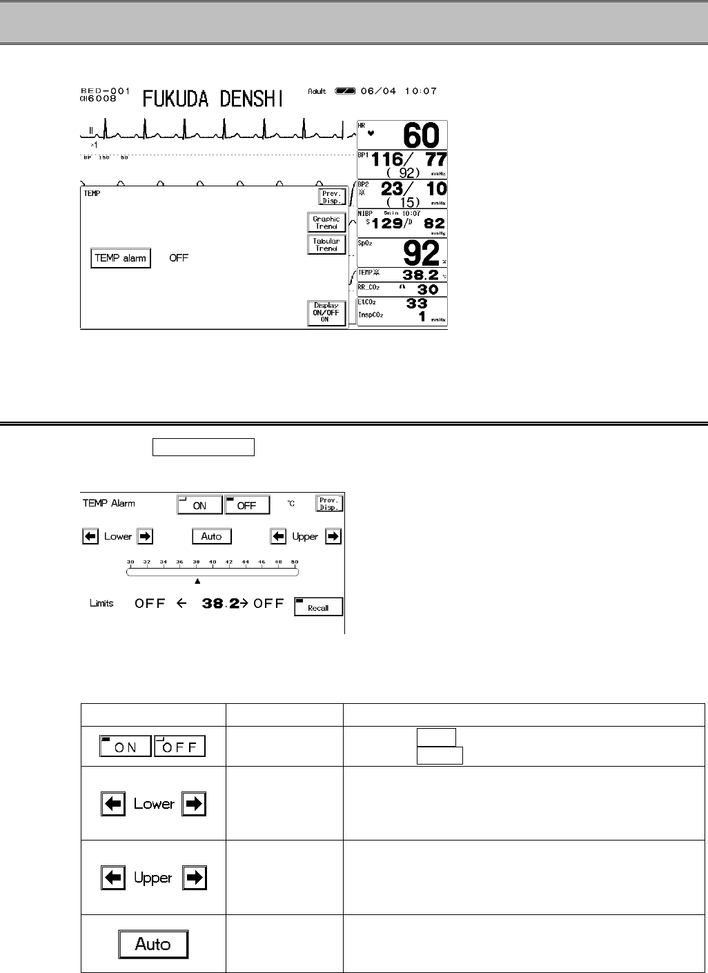
Temperature Alarm
1. Press the TEMP Alarm key to display the alarm setup menu.
Select ON/OFF of temperature alarm, and set the upper and lower alarm limit.
The alarm limit can be set for each measurement unit (?C / ?F).
The upper and lower limit can be set in increments of 0.5?C / 0.5?F.
Key Item Description
Individual Alarm Selecting ON will generate the TEMP alarm.
Selecting OFF will not generate the TEMP alarm.
Lower Alarm
Limit
Sets the lower alarm limit (30.0∼49.0?C / 86.0∼
120.0?F).
Setting a value 30.0?C / 86.0?F or below will turn the
alarm OFF.
Upper Alarm
Limit
Sets the upper alarm limit (31.0∼50.0?C / 88.0∼
122.0?F).
Setting a value 50.0?C / 122.0?F or above will turn the
alarm OFF.
Automatic
Setup
Automatically sets the upper limit to +2.0?C /+3.0?F
to the current value, and lower limit to−2?C /−3.0?F
to the current value.
6−37
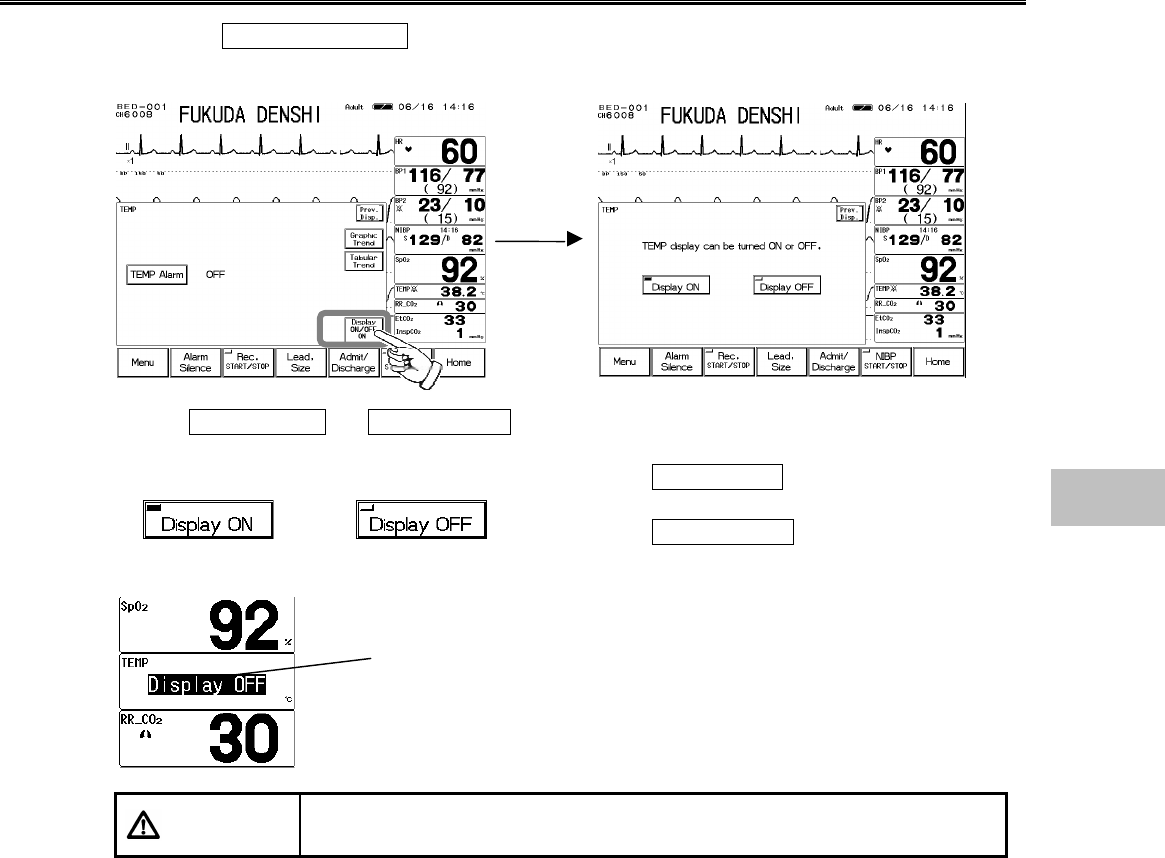
ON/OFF of Parameter Display
1. Press the Display ON/OFF key. The confirmation display for ON/OFF of TEMP display
will appear.
2. Select Display ON or Display OFF .
Pressing the Display ON key will display the
numeric data.
Pressing the Display OFF key will not display the
numeric data.
CAUTION When the waveform and numeric data display is set to OFF, the alarm
generation and tabular/graphic trend will be also set to OFF.
The Display OFF message will be
displayed inside the parameter key.
6
Temperature
6−38
− CO2 Concentration − (DS-7141)
This menu allows setup of CO2 concentration measurement.
Scale :Sets the CO2 waveform scale.
EtCO2 Alarm :Sets ON/OFF of EtCO2 alarm, and upper and lower alarm limits.
InspCO2 Alarm:Sets ON/OFF of InspCO2 alarm and upper alarm limit.
Configuration :Sets CO2 monitoring conditions.
CO2 Scale
1. Press the Scale key to display the scale setup menu.
<Scale setup menu for the unit in mmHg>
2. Select the CO2 waveform scale for displaying and recording.
For the measurement unit in mmHg, select the scale from 50 , 100 .
For the measurement unit in kPa and %, select the scale from 4 , 8 , 10 .
EtCO2 (End-Tidal CO2) Alarm
1. Press the EtCO2 Alarm key to display the alarm setup menu.
Select ON/OFF of EtCO2 alarm, and set the upper
and lower alarm limits.
Set the alarm condition for each measurement unit
(mmHg / kPa / %).
Upper and lower alarm limits can be set in increments
of 1mmHg, 0.1kPa, 0.1%.
NOTE EtCO2 alarm will not generate unless 2 or more respiration is detected
within 30 seconds after power ON or after discharge.
6−39
Key Item Description
Individual
Alarm Selecting ON will generate the EtCO2 alarm.
Selecting OFF will not generate the EtCO2 alarm.
Lower Alarm
Limit
Sets the lower alarm limit (1∼98mmHg, 0.1∼13.1kPa,
0.1∼13.1%). Setting a value equal to or below
1mmHg, 0.1kPa, 0.1% will turn the alarm OFF.
Upper Alarm
Limit
Sets the upper alarm limit (3∼100mmHg, 0.4∼
13.3kPa, 0.3∼13.3%). Setting a value equal to or
above 100mmHg, 13.3kPa, 13.3% will turn the alarm
OFF.
Automatic
Setup
Automatically sets the upper alarm limit to +10mmHg,
+1.3kPa, +1.3% to the current value, and the lower
alarm limit to −10mmHg, −1.3kPa, −1.3% to the
current value.
InspCO2 (Inspiratory CO2) Alarm
1. Press the InspCO2 Alarm key to display the alarm setup menu.
Select ON/OFF of InspCO2 alarm, and set the upper
alarm limit.
Set the alarm condition for each measurement unit
(mmHg / kPa / %).
Upper alarm limit can be set in increments of 1mmHg,
0.1kPa, 0.1%. Lower alarm limit can not be set.
NOTE InspCO2 alarm will not generate unless 2 or more respiration is detected
within 30 seconds after power ON or after discharge.
Key Item Description
Individual Alarm Selecting ON will generate the InspCO2 alarm.
Selecting OFF will not generate the InspCO2
alarm.
Upper Alarm
Limit
Sets the upper alarm limit (1∼4mmHg, 0.1∼0.4kPa,
0.1∼0.4%). Setting a value equal to or above
4mmHg, 0.4kPa, 0.4% will turn the alarm OFF.
Automatic
Setup Automatically sets the upper alarm limit to +3mmHg,
+0.4kPa, +0.4% to the current measurement.
6
CO2 Concentration
6−40
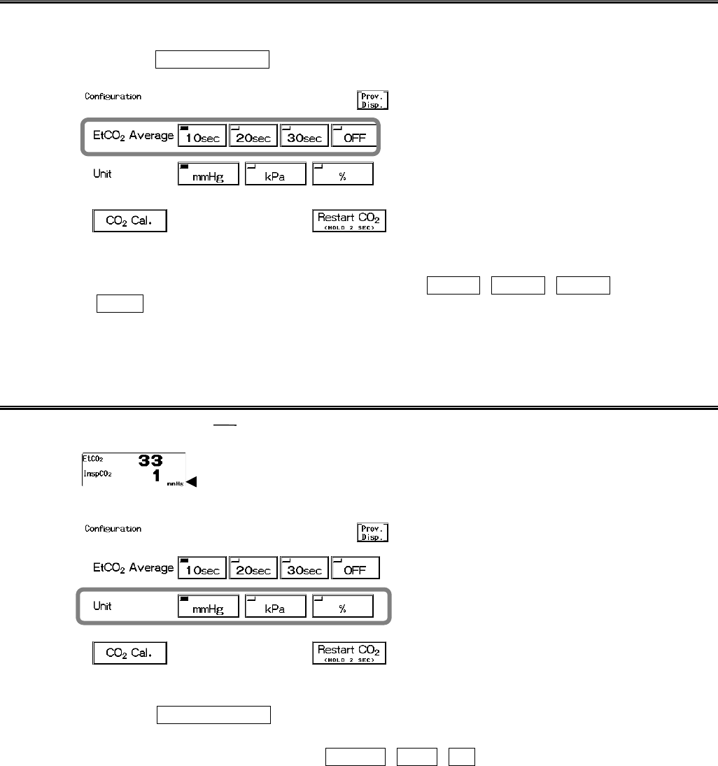
EtCO2 Average Duration
The duration to average the EtCO2 value can be selected from 10 sec., 20 sec., 30 sec., or OFF.
1. Press the Configuration key to display configuration menu for EtCO2 average duration
selection.
2. Select the average duration.
Select the duration to average the EtCO2 value from 10sec , 20sec , 30sec .
If OFF is selected, EtCO2 value for each respiration will be displayed.
As the EtCO2 value display is updated each second, EtCO2 value for each respiration can not be
displayed if respiration rate is above 60 Bpm.
Measurement Unit
The measurement unit can be selected from mmHg, kPa, or %.
Measurement Unit
1. Press the Configuration key to display the configuration menu for measurement unit
selection.
2. Select the measurement unit from mmHg , kPa , % .
The graphic trend and tabular trend will be displayed with the selected measurement unit.
If the measurement unit is changed frequently, the continuity of the graphic trend and tabular trend
may be lost.
When the measurement unit is changed, make sure to set the alarm condition for that unit. The
alarm setup is necessary for each measurement unit.
6−41
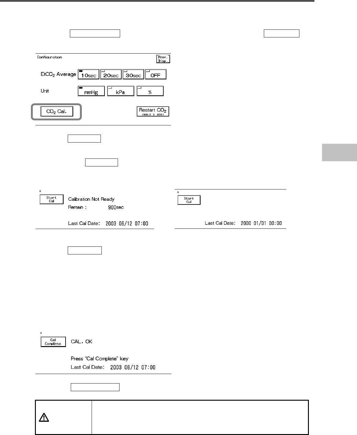
CO2 Calibration
CO2 calibration can be performed using calibration gas. Calibration should be conducted every 6
months or when any measurement error is found.
1. Press the Configuration key to display the configuration menu for CO2 Cal. key
display.
2. Press the CO2 Cal. key to display the calibration menu.
Due to precision matter, CO2 calibration can not be started until 20 minutes has elapsed after the
power is turned ON.
During this time, Start Cal key will be displayed in gray which indicates that the key is
ineffective.
The message, “Calibration not ready” and the remaining time for preparation will be displayed.
<Preparing for calibration> <Start calibration>
3. Press the Start Cal key and conduct calibration according to the displayed messages.
4. The message, “Feed CAL. GAS” will be displayed. Press the injection button to inject the
calibration gas.
5. The message, “Calc. Gas can be removed” will be displayed. Stop pressing the injection
button to cease the injection.
6. The message, “CAL. OK” will be displayed. “Last Cal. Date” will be updated to the current
date.
If any of the following messages is displayed, start the procedure again from step 2.
“CAL. error”, “CAL GAS error”, “Auto Zero fail”, “No stable gas flow”, “CAL. failure”
7. Press the Cal Complete key to end the calibration.
CAUTION
?
Perform calibration after 20 minutes from turning ON the power of the
DS-7100 system.
?
Do not disconnect the sampling tube during calibration.
If disconnected, calibration will cease.
6
CO2 Concentration
6−42
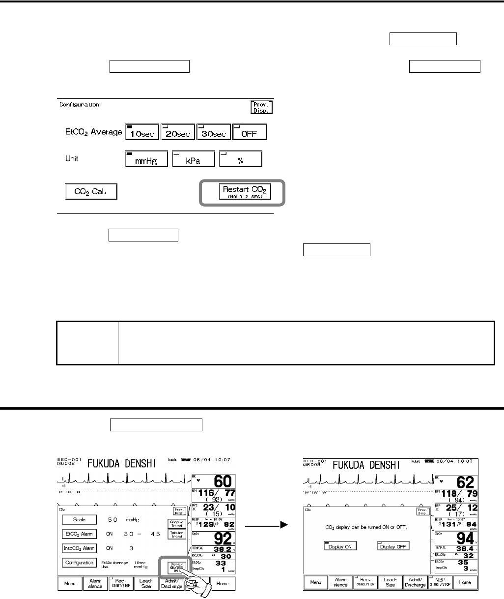
Restarting the CO2 Unit
The sampling tube will cease functioning when erroneous condition such as blocking of exhaust
tube, sampling tube or nasal prong is detected. When the pump ceases functioning, “Check CO2
unit” message will be displayed. After resolving the problem, press the Restart CO2 key and
restart the measurement.
1. Press the Configuration key to display the configuration menu for Restart CO2 key
display.
2. Press the Restart CO2 key for 2 seconds.
If the “Check CO2 unit” message is not displayed, the Restart CO2 key will not function.
3. Check that the unit is restarted.
The sampling pump will start to function, and the “Check CO2 unit” message will disappear.
Check that the message has disappeared and the measurement data is displayed.
NOTE If the “Check CO2 unit” message does not disappear after restarting the unit, the
replacement of CO2 unit part may be necessary. Contact our service
representative.
ON/OFF of Parameter Display
1. Press the Display ON/OFF key. The confirmation display for ON/OFF of CO2 display
will appear.
6−43
2. Select Display ON or Display OFF .
Pressing the Display ON key will display the
waveform and numeric data.
Pressing the Display OFF key will not display the
waveform and numeric data.
When filter line is attached to the patient with the CO2 display set to OFF, and 2 or more
respiration is detected within 30 seconds, the CO2 waveform and numeric data will be
automatically displayed.
CAUTION
?
When the waveform and numeric data display is set to OFF, the alarm
generation and tabular/graphic trend will be also set to OFF.
?
If CO2 is set as RR source, the pulse rate will also not be displayed.
The Display OFF message will be
displayed inside the parameter key.
6
CO2 Concentration
6−44
Blank Page

7−1
Function
This chapter describes the functions such as arrhythmia analysis, trend, and recall.
Chapter 7
− Arrhythmia Analysis −Definition, etc. ・・・・・ 2
Arrhythmia Definition・・・・・・・・・・・・・・・・・・・・・・・・・・ 2
●QRS Classification ・・・・・・・・・・・・・・・・・・・・・・・・・2
●Arrhythmia Type ・・・・・・・・・・・・・・・・・・・・・・・・・・・2
To Set the Arrhythmia Alarm ・・・・・・・・・・・・・・・・・・・ 3
To Perform Arrhythmia Learning・・・・・・・・・・・・・・・・ 4
− Graphic Trend Data−Display / Record ・・・・・ 6
To Display the Graphic Trend ・・・・・・・・・・・・・・・・・・ 6
The Description of the Display・・・・・・・・・・・・・・・・・ 10
− Tabular Trend −Display / Record ・・・・・・・・・・・・ 11
To Display the Tabular Trend ・・・・・・・・・・・・・・・・・11
The Description of the Display・・・・・・・・・・・・・・・・・ 12
Parameter Setup for Tabular Trend ・・・・・・・・・・・・13
− Recall Data−Display / Record ・・・・・・・・・・・・・14
To Display the Recall Menu・・・・・・・・・・・・・・・・・・・ 14
●Recall List Display・・・・・・・・・・・・・・・・・・・・・・・・ 14
●To Display and Record the Enlarged Recall
Waveform・・・・・・・・・・・・・・・・・・・・・・・・・・・・・・・・・ 15
To Set the Recall Condition ・・・・・・・・・・・・・・・・・・・17
− OCRG −Display ・・・・・・・・・・・・・・・・・・・・・・・19
− ST Display − ST Display, Alarm Setup, etc.・20
To Display the ST Measurement Menu ・・・・・・・・・20
●To Set the Reference Waveform ・・・・・・・・・・・ 21
●ST Alarm Setup ・・・・・・・・・・・・・・・・・・・・・・・・・・ 22
− NIBP List −Display / Record ・・・・・・・・・・・・・23
To Display the NIBP List・・・・・・・・・・・・・・・・・・・・・・23
The Description of the Display・・・・・・・・・・・・・・・・・ 24
− Other Bed ―Display / Alarm ・・・・・・・・・・・・・・ 25
Other Bed Display ・・・・・・・・・・・・・・・・・・・・・・・・・・・ 25
Other Bed Alarm Setup・・・・・・・・・・・・・・・・・・・・・・・ 26
7
Function
7−2
− Arrhythmia Analysis −Definition, etc.
This section explains the arrhythmia analysis and alarm setup procedure.
Arrhythmia Definition
The arrhythmia detection is performed by learning the normal waveform of the patient and
determining VPC by comparing the waveform (QRS pattern) and R-R interval of each heart beat.
A pattern matching is performed with the VPC detected from R-R interval, QRS amplitude, QRS
area, QRS polarity, etc., and determines as VPC after discriminating the noise and VPC.
●QRS Classification
The QRS analysis is performed by comparing with the learned waveform and QRS pattern
matching.
N (Normal) Normal QRS beat
V (VPC) Ventricular Extrasystole
? (Undetermined beat) Learning arrhythmia, or beat not matching the pattern
P (Pacing beat) Pacing beat
F (Fusion beat) Fusion beat of pacing and spontaneous beat
S (SVPC) Supraventricular Extrasystole
●Arrhythmia Type
The alarm is generated according to the arrhythmia classification by the pattern or HR of normal
QRS and VPC determined QRS.
Type Meaning Detection Criteria
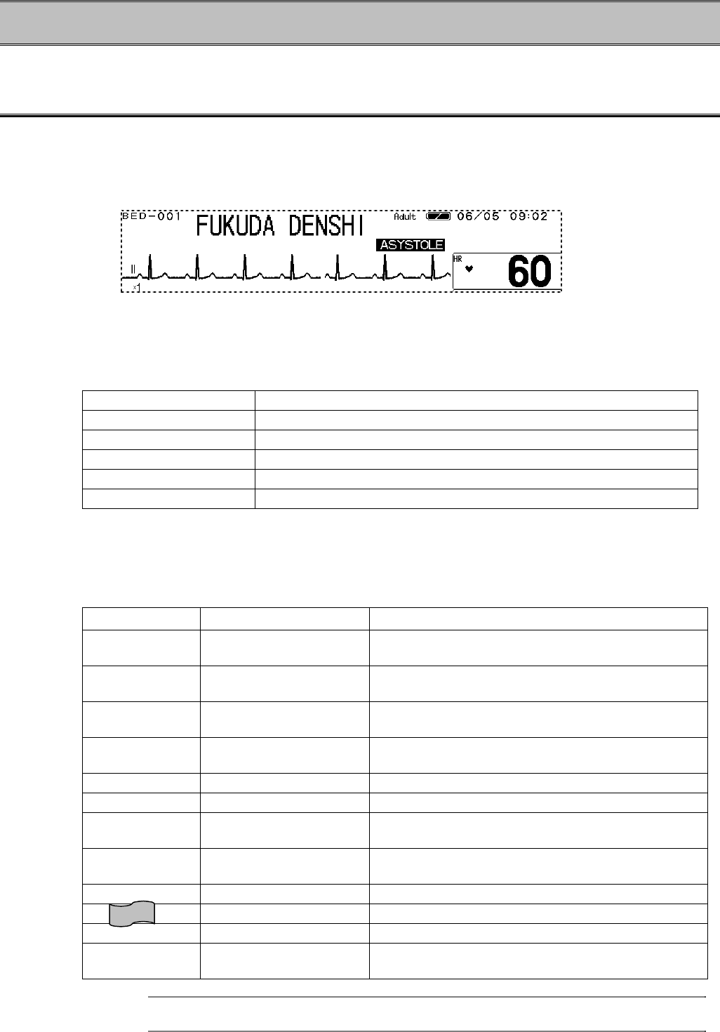
ASYSTOLE Cardiac Arrest Cardiac arrest is detected for more than
preprogrammed time.
VF Ventricular Fibrillation A random, rapid electrical activity of the heart is
detected.
VT Ventricular Tachycardia 9 or more continuous ventricular beats are detected.
(HR: 140bpm / 120bpm or over)
SLOW_VT 9 or more continuous ventricular beats are detected.
(HR: under 140bpm / 120bpm)
TACHY Tachycardia HR is over the upper alarm limit.
BRADY Bradycardia HR is below the lower alarm limit.
RUN Consecutive VPC Continuous VPC exceeding the preprogrammed
value is detected.
COUPLET Couplet Ventricular
Extrasystole 2 continuous beats of VPC is detected.
PAUSE Cardiac arrest of 1.5 seconds or more is detected.
BIGEMINY Ventricular Bigeminy QRS pattern of V-N-V-N-V-N is detected.
TRIGEMINY Ventricular Trigeminy QRS pattern of V-N-N-V-N-N is detected.
FREQUENT Frequent VPC VPC exceeding the preprogrammed value is
detected within 1 minute.
Reference
Refer to “8. System Configuration Ward Setup” for setup of HR reference for VT analysis.
7−3
WARNING
Objective and constant arrhythmia detection is possible through the fixed
algorithm incorporated in this monitor.
However, excessive waveform morphology change, motion artifact, or
the inability to determine the waveform pattern may cause an error, or fail
to make adequate detection. Therefore, physicians should make final
decisions using manual recording, alarm recording and recall waveform
for evaluation.
CAUTION
For proper arrhythmia detection and ECG monitoring, verify proper
electrode placement, lead selection, and ECG waveform size. If
necessary, turn ON the AC filter. Improper electrode placement, lead
selection, and ECG waveform size can cause errors in detection.
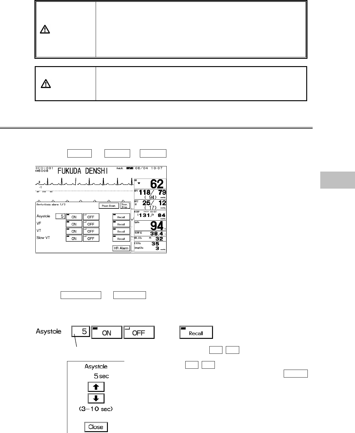
To Set the Arrhythmia Alarm
ON/OFF of arrhythmia alarm and reference of arrhythmia analysis can be set.
1. Press the Menu → Alarm → Arrhy. keys.
<Arrhythmia Alarm Setup (1/3) Menu>
The arrhythmia alarm setup menu consists of 3 pages.
Page 1/3 : ASYSTOLE, VF, VT, SLOW_VT
Page 2/3 : RUN, BIGEMINY, TRIGEMINY, PAUSE
Page 3/3 : COUPLET, TACHY, BRADY, FREQUENT
Use the Page Down or Page Up keys to switch the pages.
2. Set the reference range.
Pressing the reference value key will display the ? ? keys.
Use the ? ? keys to set the reference value.
After setting the reference value, press the Close
key.
7
Arrhythmia Analysis
7−4
<Arrhythmia Reference Range>
Arrhythmia Reference Range Default
ASYSTOLE 3 sec.∼10 sec. 5 sec.
RUN 2 beats∼8beats 3 beats
PAUSE 1.5 sec. ∼5 sec. 3 sec.
FREQUENT 1 beat∼50 beats/min. 10 beats/min.
3. Select ON or OFF for the alarm.
Alarm will generate. Alarm will not generate
4. Select ON or OFF for recall factor.
ON/OFF of recall factor can be set on the alarm setup menu.
Will be selected as recall factor.
Will not be selected as recall factor.
Pressing the Recall key will switch the ON/OFF selection.
To Perform Arrhythmia Learning
Learning of normal ECG largely affects the accuracy of arrhythmia analysis.
If any error occurs in arrhythmia detection and QRS judgement, performing arrhythmia learning
will recover the original analyzing accuracy.
Arrhythmia learning will be performed for about 20 beats for the normal ECG, but it may take
longer if the heartbeat is unstable.
During arrhythmia learning, arrhythmia alarm other than ASYSTOLE, TACHY, BRADY will not be
generated.
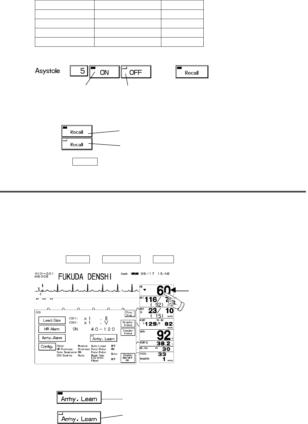
1. Press the Menu → Parameter → ECG keys.
<ECG Parameter Setup Menu>
2. Start arrhythmia learning.
Learning arrhythmia
Pressing the key with the LED off will start arrhythmia learning.
Pressing the HR parameter key will also display
the ECG parameter setup menu.
7−5
Pressing the key while learning arrhythmia will not stop the learning.
3. During arrhythmia learning, a message will be displayed.
7
Arrhythmia Analysis
7−6
− Graphic Trend Data−Display / Record
This section explains the graphic trend function and recording procedure.
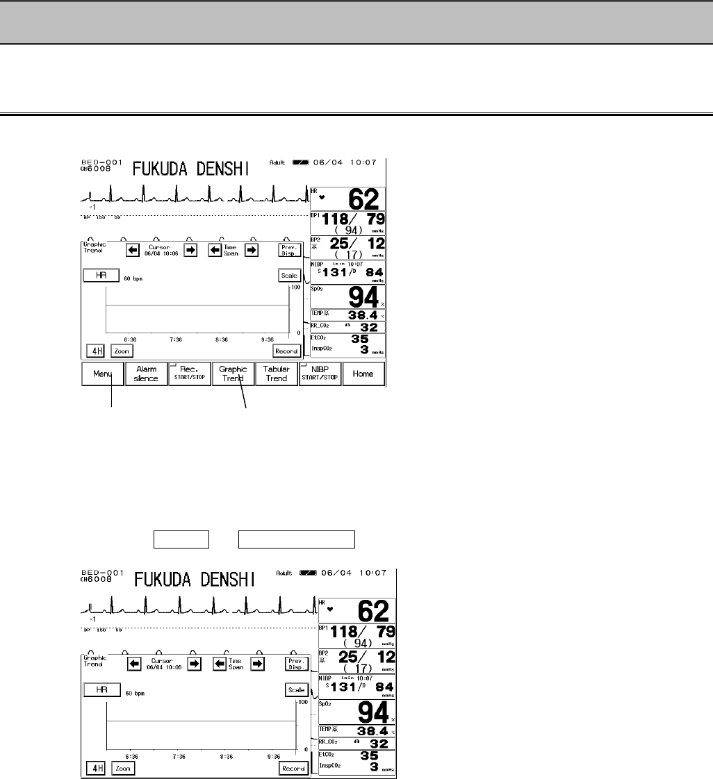
To Display the Graphic Trend
The graphic trend menu can be accessed from the menu, or from the preprogrammed user key.
The 24 hours of graphic trend data in 1-minute interval will be automatically stored and displayed if
the data is displayed on the home display.
1. Press the Menu → Graphic Trend keys to display the graphic trend menu.
To display from the menu To display from the user key.
7−7
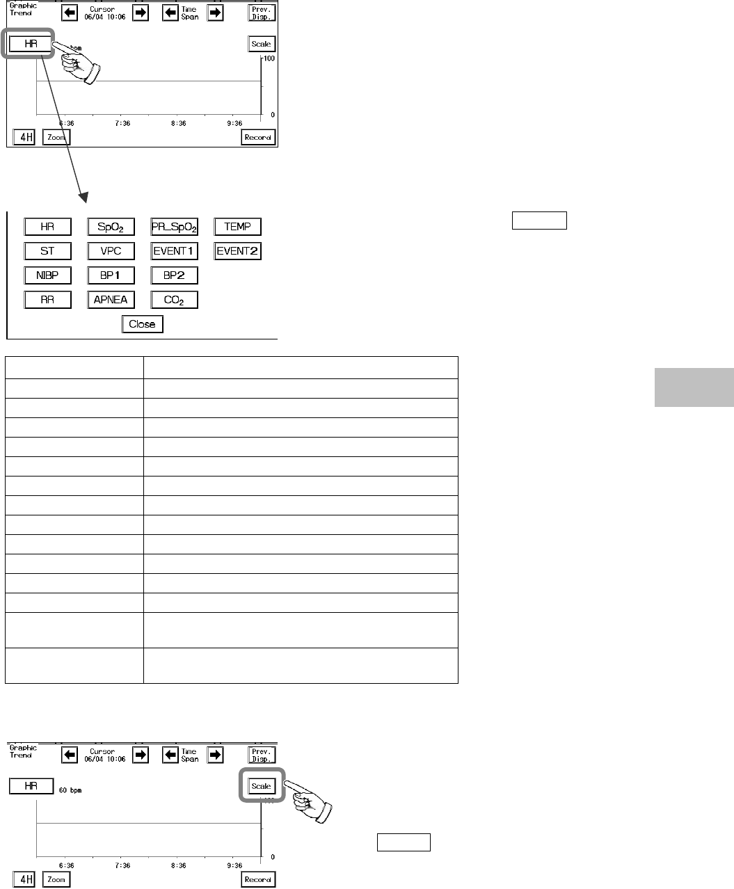
2. Select the parameter to display.
Pressing the parameter selection key will display the
selection for display.
Select a parameter and press the Close key.
Parameter Description
HR HR, PR (SpO2, BP)
ST ST1, ST2
VPC VPC beats
BP1 BP1 (SYS / Mean / DIA)
BP2 BP2 (SYS / Mean / DIA)
NIBP NIBP (SYS / DIA)
SpO2SpO2 value
PR_ SpO2SpO2 pulse rate
TEMP Temperature
RR Respiration Rate (Impedance, CO2)
APNEA Apnea Time (Impedance, CO2)
CO2EtCO2 / InspCO2
EVENT1 ASYSTOLE, VF, VT, SLOW_VT, RUN,
BIGEMINY
EVENT2 TRIGEMINY, PAUSE, COUPLET, TACHY,
BRADY, FREQUENT
3. Select the scale for display.
Pressing the Scale key will switch the scale
according to the displayed parameter as shown
below.
7
Graphic Trend Data
7−8
Parameter Scale Unit
HR 100, 200, 300 bpm
±0.2, ±0.5, ±1.0, ±2.0 mV
ST ±2, ±5, ±10, ±20 mm
VPC 20, 50, 100 beat
20, 50, 100, 150, 200, 300 mmHg
BP1, BP2 4, 8, 16, 20, 24, 40 kPa
100, 150, 200, 300 mmHg
NIBP 16, 20, 24, 40 kPa
SpO20∼100, 50∼100, 80∼100 %
PR_ SpO2100, 200, 300 bpm
20∼45, 30∼40 ?C
TEMP 68∼113, 86∼104 ?F
RR 50, 100, 150 Bpm
APNEA 15, 30 Sec
4.0, 8.0, 10.0 %, kPa
CO250, 100 mmHg
EVENT none
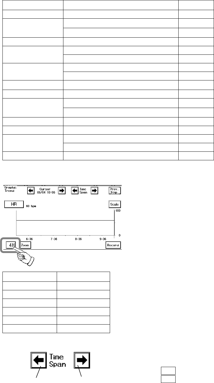
4. Select the display time range.
Pressing the time range key will sequentially change
the key as follows; 1H→2H→4H→8H→12H→24H→
1H
Time Range Resolution
1 hour 1 min.
2 hour 1 min.
4 hour 1 min.
8 hour 1 min,
12 hour 3 min.
24 hour 3 min,
5. Select the time span.
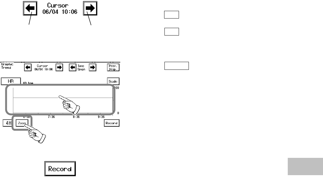
Scrolls to past Scrolls to present
Scrolls the graphic trend display to past or present data
with the selected time range.
Pressing the ? key will scroll to the past data.
Pressing the ? key will scroll to the present data.
7−9
6. Move the cursor.
Scrolls to past Scrolls to present
The data of selected time can be displayed by moving
the cursor.
Pressing the ? key will scroll to the past data with
the selected time range.
Pressing the ? key will scroll to the present data.
7. Enlarge the display.
Pressing the Zoom key will display the 1-hour
data with the cursor time in center.
Directly pressing the graphic trend display area will
also display the 1-hour data with the pressed time in
center.
8. Store the graphic trend data.
The displayed graphic trend data will be stored. 7
Graphic Trend Data
7−10
The Description of the Display
The measured data will be compressed for the 12-hour / 24-hour display.
Parameter Compressed Form
HR Mean Value
ST Mean Value
VPC Maximum Value
BP1, BP2 Mean Value
NIBP Current Value
SpO2Mean Value
PR Mean Value
TEMP Mean Value
RR Mean Value
APNEA Maximum Value
CO2Mean Value
EVENT Logical Sum
Cursor
Scale
Cursor Time
Measurement Data at Cursor Time
Real time scale
7−11
− Tabular Trend −Display / Record
This section explains the tabular trend function and recording procedure.
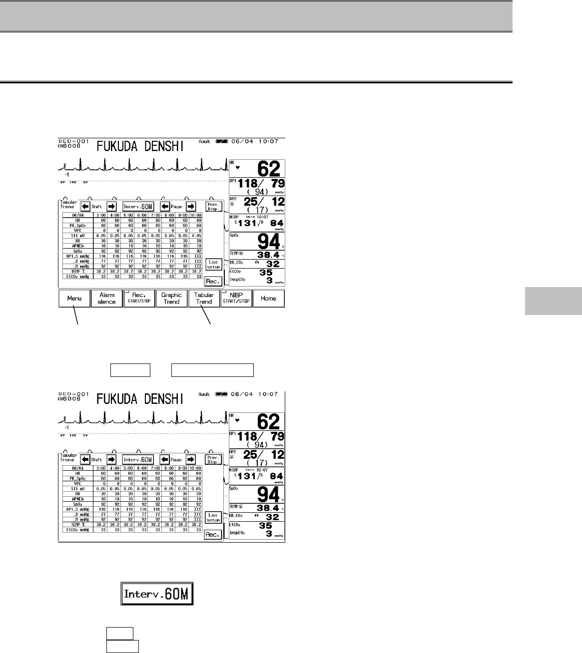
To Display the Tabular Trend
The tabular trend menu can be accessed from the menu, or from the preprogrammed user key.
The 24 hours of data in 1-minute interval will be automatically stored and displayed if the data is
displayed on the home display.
1. Press the Menu → Tabular Trend keys to display the tabular trend.
2. Select the time interval.
Pressing the key will sequentially select the time
interval as follows; 1M→5M→10M→15M→30M→
60M→1M
Selecting 5M will display the data in real time such as 10:00, 10:05, 10:25.
Selecting 60M will display the data in real time such as 10:00, 11:00, 12:00.
If the list is displayed at 10:35, the data from 10:00 will be displayed.
Display from the menu Display from the user key.
7
Tabular Trend
7−12
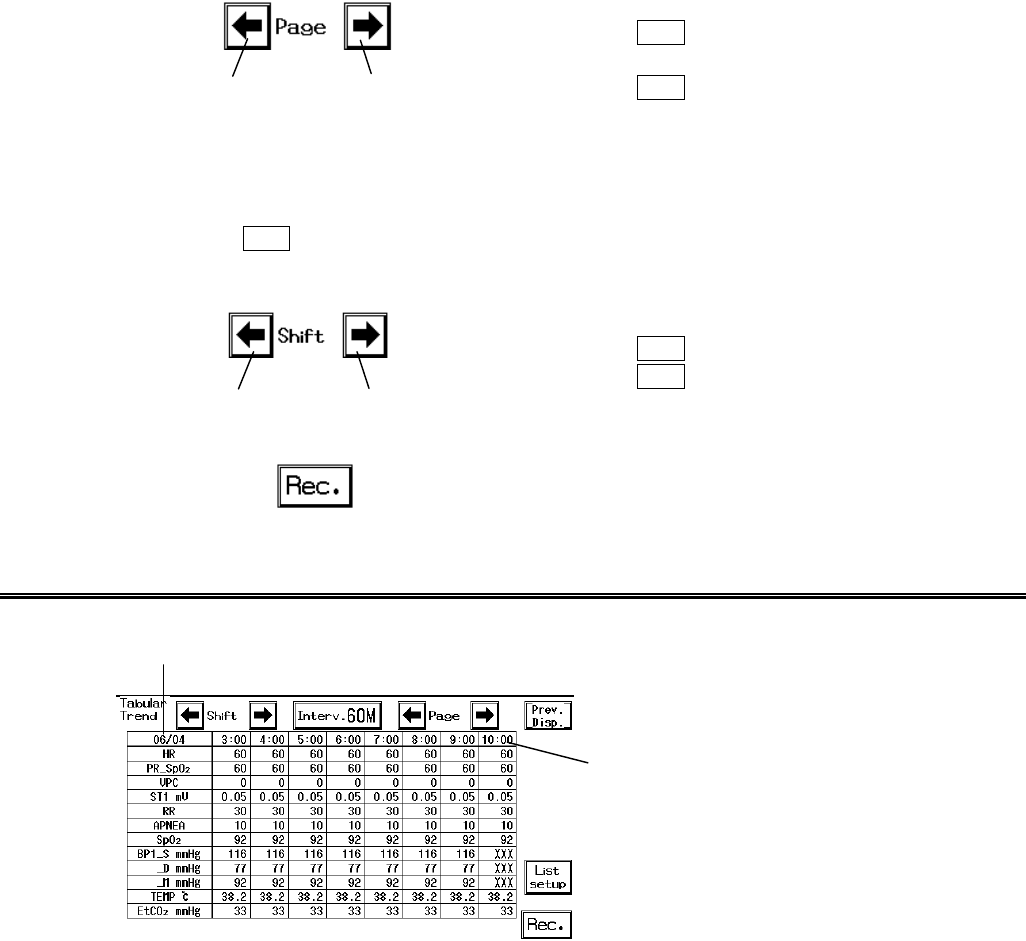
3. Shift the page.
Shift to past Shift to present
The page can be shifted past or present by page with
the selected time range.
Pressing the ? key will shift one page to the past
data.
Pressing the ? key will shift one page to the
present data.
The data will be listed in 8 columns.
If 5-minute time range is selected and the starting time on the list is 10:00, 35 minutes from 10:00
to 9:25 will be listed in 1 page.
Pressing the ? key will display the list from 9:20 to 8:45.
4. Shift the displayed column.
Shift to past Shift to present
The list data can be shifted in displayed columns.
Pressing the ? key will shift the display to past.
Pressing the ? key will shift the display to present.
5. Store the list data.
The displayed list data will be stored.
The Description of the Display
If the data is within 24 hours or if the monitoring is suspended, the time will be displayed as “??:??”.
Also, if the data is not displayed on the home display, or the BP is not zero balanced, the data will
be displayed as “ー ー ー”.
Starting Time
Starting Date
7−13
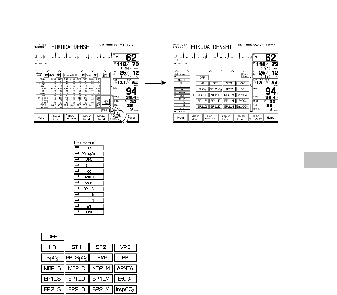
Parameter Setup for Tabular Trend
The parameters for tabular trend can be selected.
1. Press the List Setup key on the tabular trend menu to display the tabular trend setup
menu.
2. Select the position on the list.
Select the position.
There are 12 positions on the list to set the parameter.
3. Select the parameter for display.
Select the parameter to display for the previously
selected position. The position will automatically shift
downward so that consecutive parameter selection is
possible.
7
Tabular Trend
7−14
− Recall Data−Display / Record
This section explains the recall menu function and recording procedure.
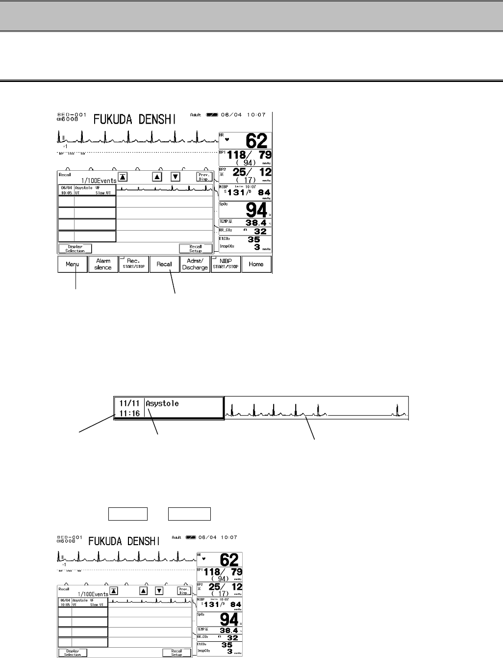
To Display the Recall Menu
The recall menu can be accessed from the menu, or from the preprogrammed user key.
When the alarm factor assigned on the recall setup occurs, the assigned waveform and the
numeric data at alarm occurence can be stored for up to 100 data.
The recall data to be displayed can be selected on the display selection menu.
On the recall list display, 5 compressed recall waveform will be displayed. Pressing one of the
compressed recall waveform will enlarge the waveform.
●Recall List Display
1. Press the Menu → Recall keys to display the recall menu.
The alarm occurrence time, the recall factor occurred at the same time, and the compressed
waveform of recall waveform 1 will be displayed.
Recall Waveform (Compressed)
Recall Factor
Time at Alarm Occurrence
Display from the menu Display from the user key
7−15
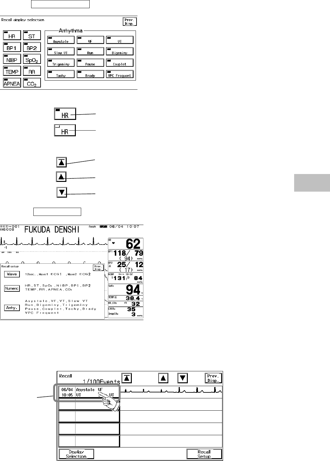
2. Select the recall factor to display on the recall list.
Press the Display Selection key and select the recall factor.
Select the numeric data, arrhythmia to display as recall factor.
If the key LED is lighted, recall data will be displayed.
If the key LED extinguished, recall data will not be displayed.
3. Shift the recall list display.
The newest 5 data will be displayed from the recall list.
Shift the recall list to newer data by 1 page (5 data).
Shift the recall list to older data by 1 page (5 data).
4. Press the Recall Setup key. The recall factor and recall waveform can be selected on
the recall setup menu.
●To Display and Record the Enlarged Recall Waveform
On the recall list display, pressing one of the recall factor will display the enlarged recall waveform.
On the enlarged recall waveform display, the recall waveform will be displayed in 25mm/s and by
using the cursor, the data before and after the alarm occurrence can be checked.
Recall Selection
7
Recall Data
7−16
1. Pressing one of the recall factors will display the enlarged recall waveform.
2. Shift the waveform left or right.
The recall waveform display can be shifted to left or
right.
? key will shift to the older data.
? key will shift to the newer data.
3. The alarm factor occurred at the same time will be displayed.
Pressing the recall factor key will display the recall
factor occurred at the same time.
4. Store the recall waveform.
Pressing the Rec. key will store the displayed
recall waveform and numeric data.
QRS Classification
Recall Waveform 1
Recall Waveform 2
Scale in seconds
Measured Data
7−17
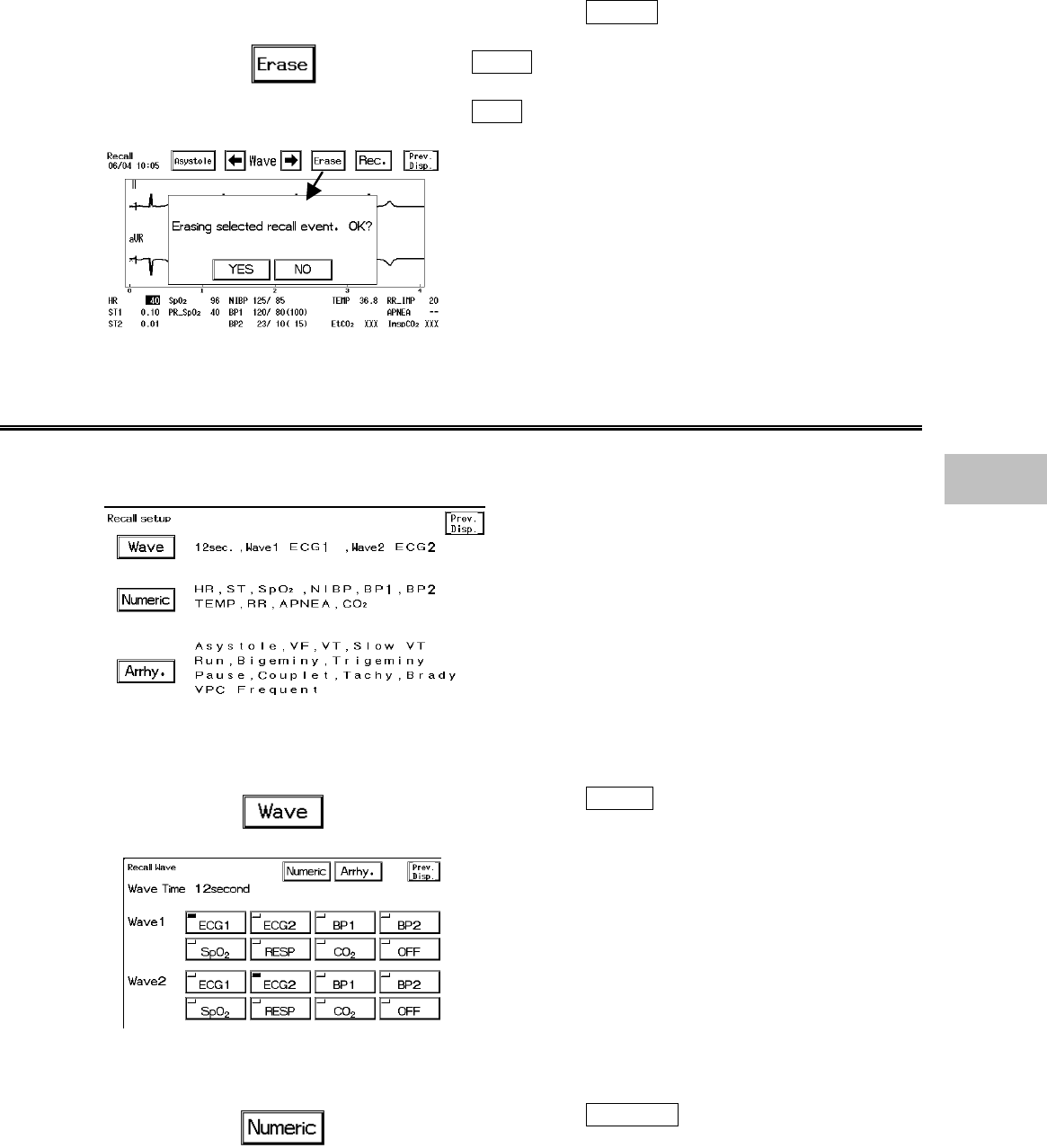
5. Erase the recall waveform.
Erase the unnecessary recall waveform.
Pressing the Erase key will display the
confirmation message.
YES will erase the waveform and displays the
recall list display.
NO will return to the previous display.
To Set the Recall Condition
On the recall menu, the storing condition at alarm occurrence can be set.
The recall waveform and recall factor (numeric data, arrhythmia) can be selected.
1. Select the recall waveform.
Pressing the Wave key will display the menu to
select the recall waveform.
Up to 2 waveforms can be selected for recall
waveform.
Select the recall waveform from No. 1 waveform and
No. 2 waveform. The key with the LED lighted is the
selected waveform.
2. Select the recall factor (numeric data).
Pressing the Numeric key will display the menu to
select the numeric data recall factor.
7
Recall Data
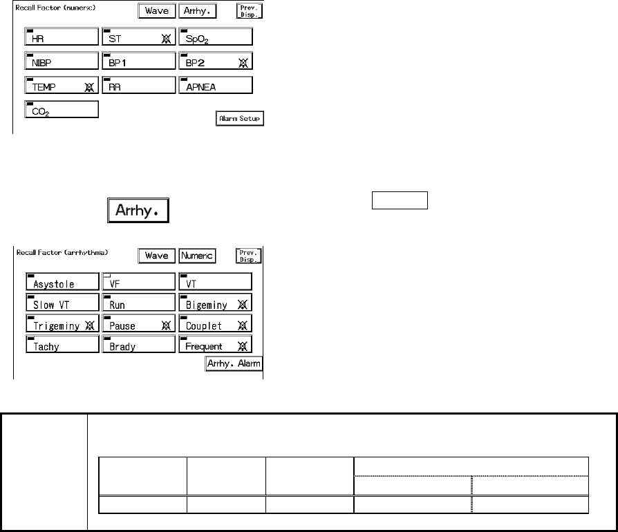
7−18
Select the recall factor by pressing the keys.
The key with the LED lighted will be the recall factor.
3. Select the recall factor (arrhythmia).
Pressing the Arrhy. key will display the menu to
select the arrhythmia alarm factor.
Select an arrhythmia for recall factor. The key with
LED lighted will be the recall factor.
The recall waveform will start with the following delay time tracing back from
the alarm occurrence.
Neonate
Adult Child Meas. Data Alarm Arrhy. Alarm
Delay Time 12sec. 12sec. 8sec. 12sec.
NOTE
7−19
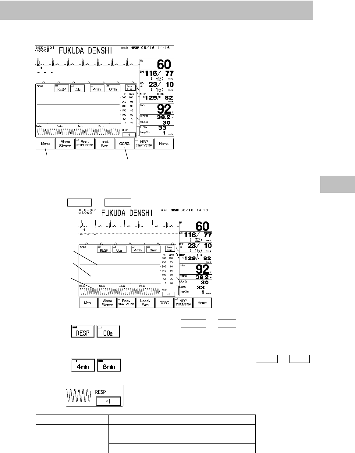
− OCRG −Display
This section describes the procedure for OCRG display.
The OCRG display can be accessed from the menu, or from the preprogrammed user key.
On the OCRG display, compressed respiration waveform, HR trend and SpO2 trend are displayed
simultaneously.
1. Press the Menu → OCRG keys to display the OCRG menu.
The trend scale is a fixed scale.
HR :0∼300bpm
SpO2:70∼100%
2. Select the respiration waveform.
Select RESP or CO2 to display the
compressed respiration waveform from impedance
respiration (RESP) or CO2 waveform.
3. Select the displaying duration.
Select a displaying duration from 4min or 8min .
4. Select the waveform size for compressed respiration waveform.
Pressing the size key will sequentially change the
waveform size.
Respiration Waveform Size, Scale
Impedance, RESP ×1/4→×1/2→×1→×2→×4→×1/4
100→50→100 (unit : mmHg)
CO24→8→10→4 (unit : % or kPa)
Display from the menu Display from the user key
SpO2 trend
HR trend
Compressed
respiration
waveform
7
OCRG
7−20
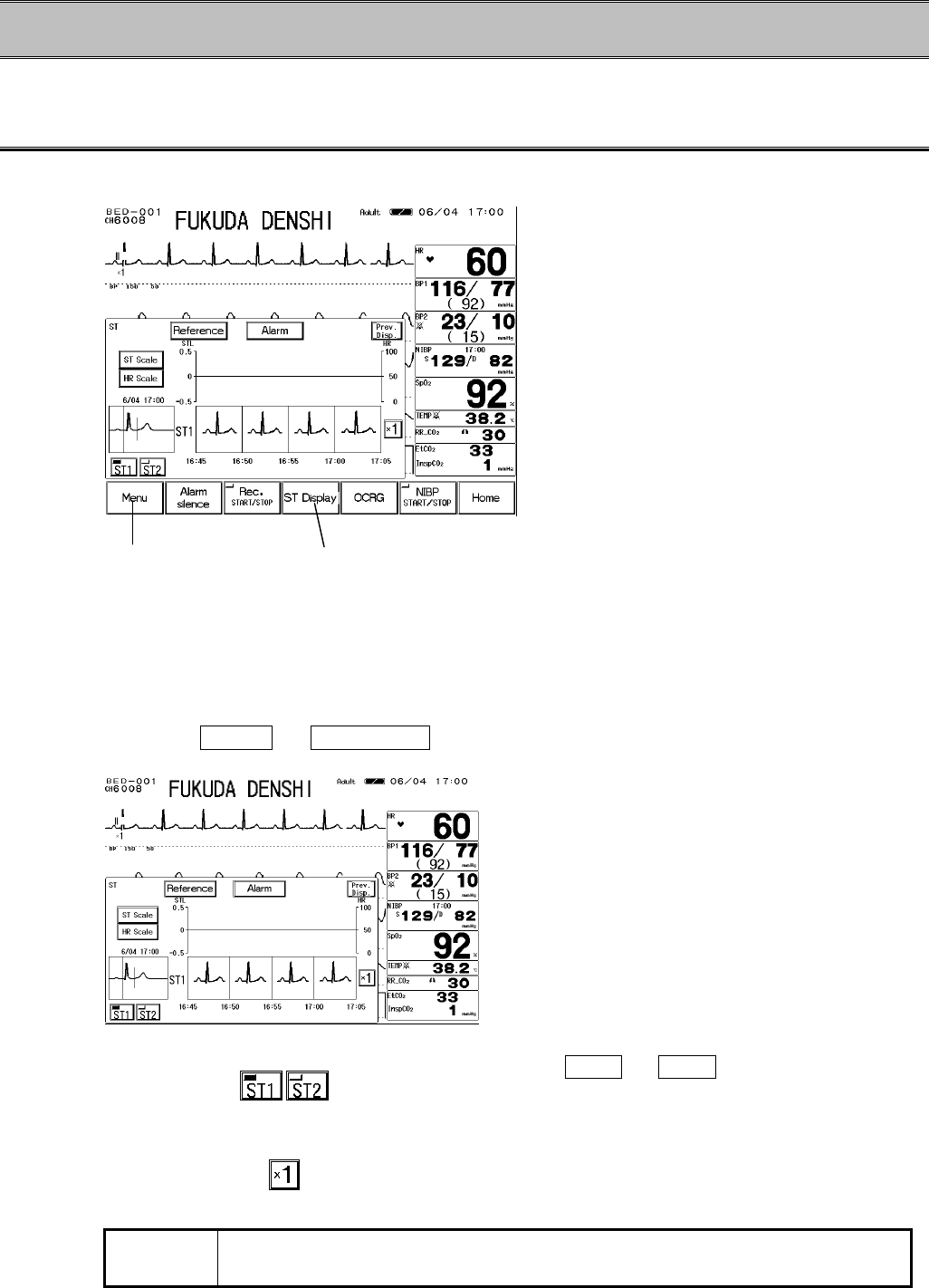
− ST Display − ST Display, Alarm Setup, etc.
This section describes the operation procedure for the ST display and alarm setup.
To Display the ST Measurement Menu
The ST display can be accessed from the menu, or from the preprogrammed user key.
On the ST display, the averaged ECG waveform of 16 beats will be superimposed for 5 minutes.
3 frames of superimposed waveform will be displayed. Also, HR and ST level will be
simultaneously displayed as graphic trend. ST1 will be measured from ECG1, and ST2 will be
measured from ECG2. On the ST display, ST alarm limit and ST reference point / measurement
point can be set.
1. Press the Menu → ST Display keys to access the ST display.
2. Select the superimposed waveform.
Press the ST1 or ST2 key to select the
superimposed waveform.
3. Select the waveform size for the superimposed waveform.
Pressing the key will sequentially change the key as
follows; ×1/4→×1/2→×1→×2→×4→×1/4.
NOTE The selection of displayed waveform size for the superimposed waveform
interlocks with ECG waveform size.
Display from the menu Display from the user key
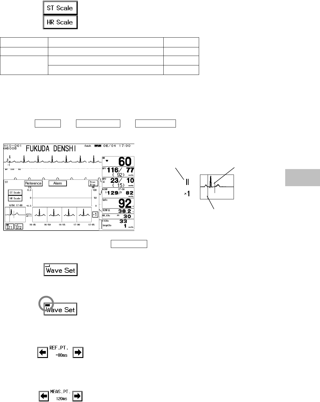
7−21
4. Select the trend scale.
Select the displayed scale for the trend.
Trend Scale Unit
HR 100, 200, 300 bpm
±0.2, ±0.5, ±1.0, ±2.0 mV
ST ±2, ±5, ±10, ±20 mm
●To Set the Reference Waveform
Set the reference waveform for the ST display and set the reference point and measurement point
on the reference waveform.
1. Press the Menu → ST Display → Reference keys to display the reference
waveform setup menu.
2. Read the waveform by pressing the Wave Set key.
16 beats average of the ECG judged as normal QRS
by arrhythmia analysis will be read. If during
arrhythmia learning, or if VPC is present, the
reference waveform setup will take for more than 16
beats.
During the reference waveform setup, the key LED
will light.
3. Set the reference point on the ST display.
The reference point can be set in the range of -240ms
∼0ms in increments of 10mS from the peak of QRS
to the P wave direction.
4. Set the measurement point on the ST display.
The measurement point can be set in the range of
0ms∼560ms in increments of 10mS from the peak of
QRS to the T wave direction.
Measurement
Point
Reference
Point
Size / Lead 7
ST Measurement
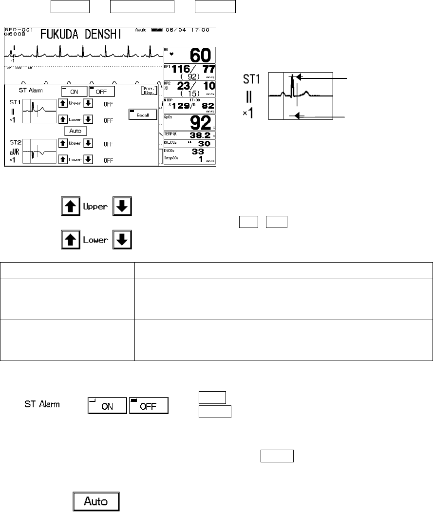
7−22
●ST Alarm Setup
The ST upper value and lower value compared with the reference waveform will be set.
The alarm value is to be set for each measurement unit (mm / mV). The upper and lower limit
can be set in 1mm / 0.1mV increment.
1. Press the Menu → ST Display → Alarm keys to display the alarm setup menu.
2. Set the upper and lower alarm limit.
Use the ? , ? keys to adjust the alarm limit.
Item Description
Lower Alarm Limit Select the lower alarm limit (±20mm / ±2.0mV).
Alarm will be set to OFF if the value −20mm / −2.0mV or
lower is selected.
Upper Alarm Limit Select the upper alarm limit (±20mm / ±2.0mV).
Alarm will be set to OFF if the value +20mm/+2.0mV or
above is selected.
3. Select ON/OFF of ST alarm.
ON will generate the ST alarm.
OFF will not generate the ST alarm.
4. Select “Auto” for automatically setting the alarm limit.
Pressing the Auto key will automatically set the
upper alarm limit to current ST value +0.2mV (+2mm),
and lower alarm limit to current ST value -0.2mV
(-2mm).
Selecting “Auto” will automatically turn ON the ST
alarm.
If the upper or lower limit is OFF, the limits will remain
to be OFF.
Upper limit cursor
Lower limit cursor
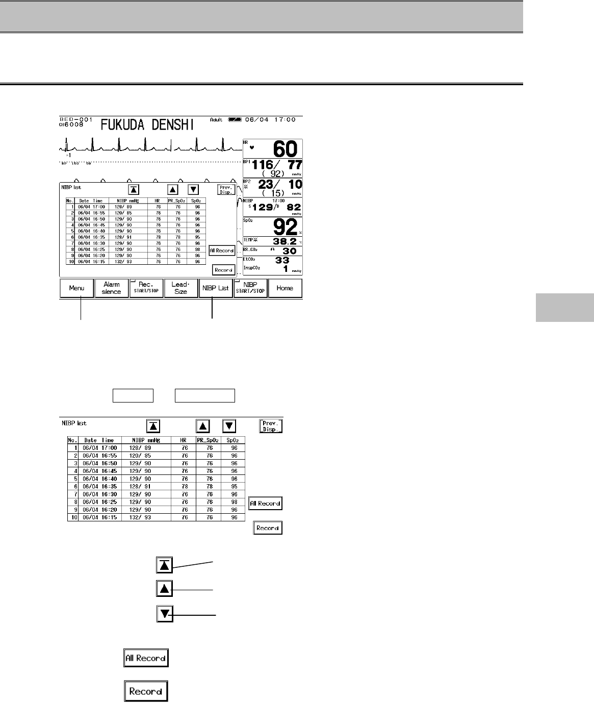
7−23
− NIBP List −Display / Record
This section explains the NIBP list function and recording procedure.
To Display the NIBP List
The NIBP list display can be accessed from the menu, or from the preprogrammed user key.
On the NIBP list, NIBP data and HR, SpO2 pulse rate, SpO2 value at the commencement of NIBP
measurement will be stored and displayed for 120 NIBP measurements.
1. Press the Menu → NIBP List keys to display the NIBP list display.
2. Shift the displayed column.
Displays the newest 10 data of the NIBP list.
Shifts the display to newer data by 1 page (10 data).
Shifts the display to older data by 1 page (10 data).
3. Record the NIBP list.
All the data stored on NIBP list will be recorded.
Currently displayed NIBP list will be recorded.
Display from the menu Display from the user key 7
NIBP List
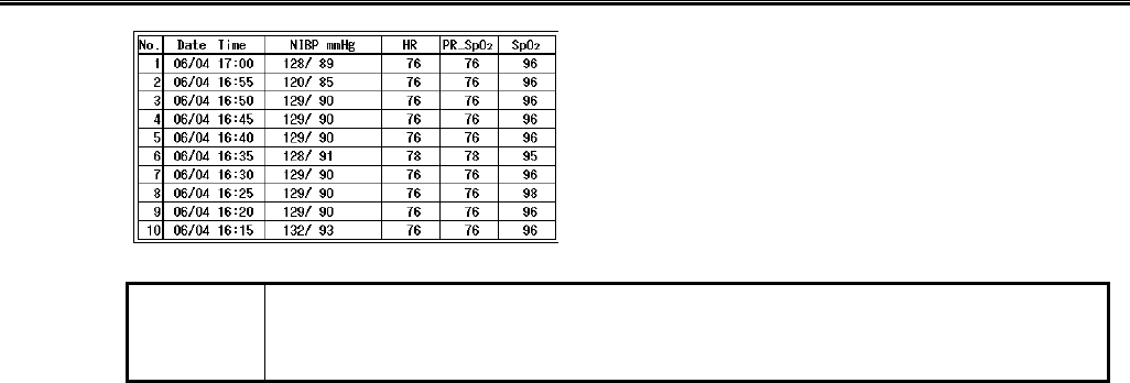
7−24
The Description of the Display
The mean BP will be displayed on the NIBP list only if
it is displayed on the home display.
If HR or SpO2 is not measured, or not correctly
measured at the commencement of NIBP
measurement, the measured data will be displayed
as “? ? ?”.
For Quick SYS measurement, only the SYS (highest
BP value) will be displayed.
NOTE If the NIBP measurement was not completed, the data will not be displayed on
the NIBP list. At the telemetry center, the time and measurement will be
displayed as “00:00” and “? ? ?” respectively.
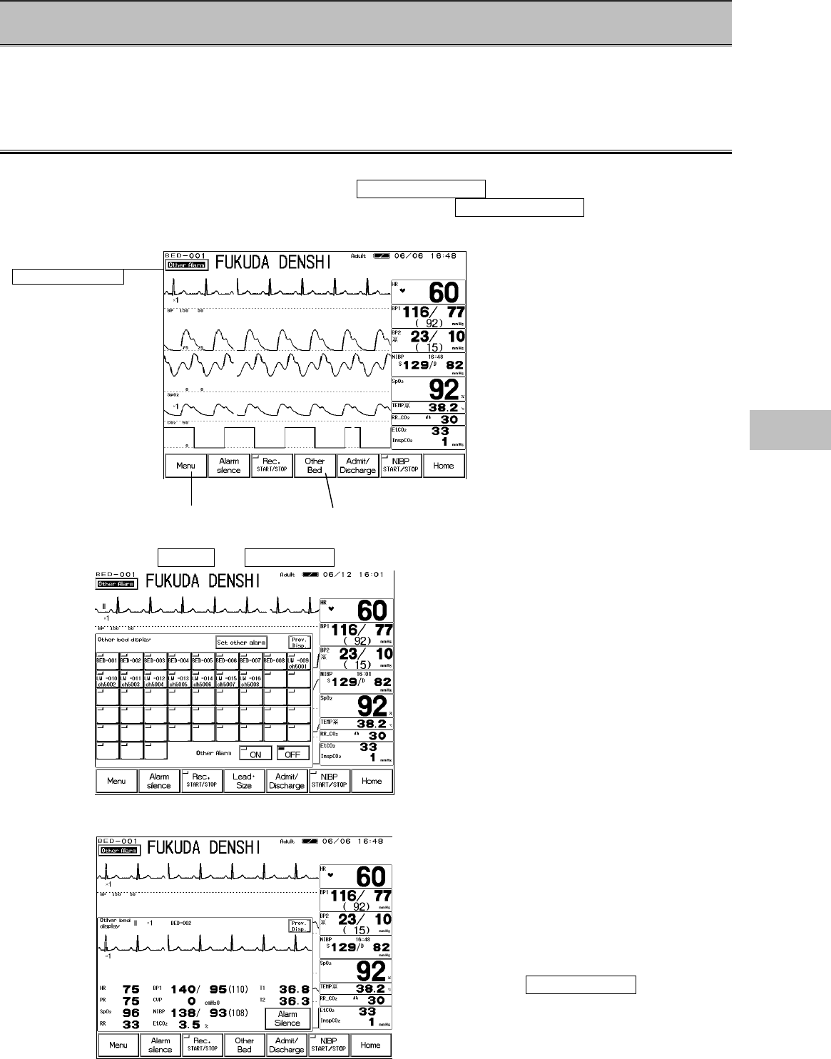
7−25
− Other Bed ―Display / Alarm
This section explains about the function to display the waveform and numeric data and to set
alarms for other bedside monitors.
To use this function, wired network connection is required.
Other Bed Display
The other bed display can be accessed from the menu or from the preprogrammed user key.
Also, by setting the other bed alarm ON, Other Bed Alarm key will be displayed when other
bedside monitor generates an alarm. By pressing this Other Bed Alarm key, the display for
the other bed can be accessed.
1. Press the Menu → Other Bed keys to display the other bed selection menu.
On the other bed selection menu, select the
Room / Bed ID to display from the 48 beds
connected to the wired network.
The Room / Bed ID for the alarm generating
bed will be displayed in red.
The bed displaying this menu will be displayed
in gray.
The key LED for the bed selected as the other
bed alarm generating bed will be lighted.
2. Press the Room / Bed ID key and access the display for the other bed.
ECG waveform and numeric data for the
selected bed will be displayed.
If an alarm is generated for this bed, the
physiological alarm / arrhythmia alarm
message will be displayed.
By pressing the Alarm Silence key on the
other bed display, the alarm sound for the
displayed bed can be silenced.
Display from the
Other Bed Alarm
key.
Display from the menu Display from the user key
7
Other Bed
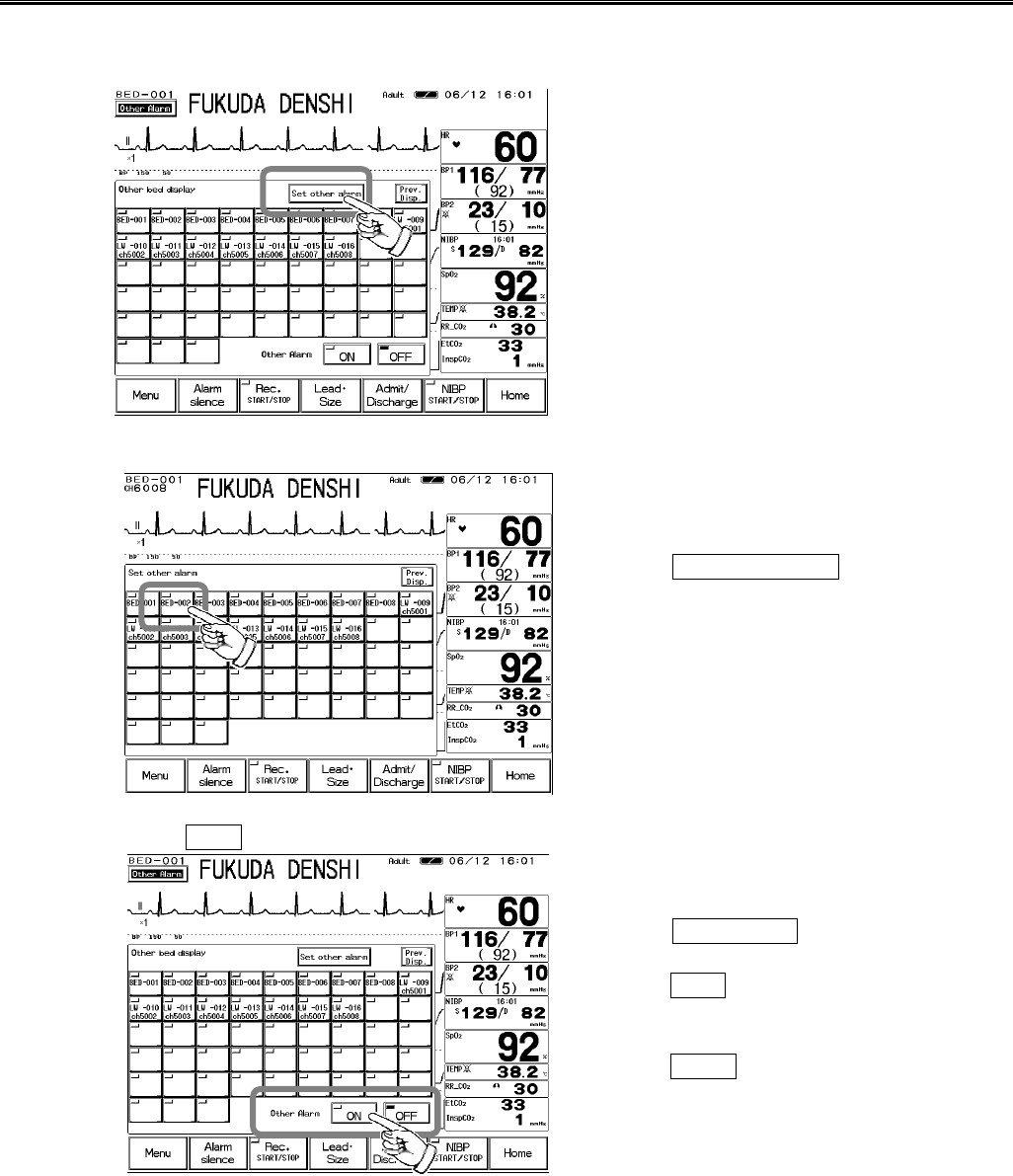
7−26
Other Bed Alarm Setup
From the 48 bedside monitors, the bed to generate the other bed alarm and ON/OFF of other bed
alarm display can be performed.
1. Select the bed to generate the other bed alarm.
Press the Set other alarm key to display the
other bed alarm setup menu.
Select the bed to generate the other bed alarm.
The key LED for the bed selected as the other
bed alarm generating bed will be lighted.
2. Select ON for the other bed alarm.
Press the Prev. Disp. key and display the
other bed selection menu.
Selecting ON will generate the other bed
alarm when an alarm generates at the other
bed.
Selecting OFF will not generate the other
bed alarm.