Fukuda Denshi Co DS7100 Patient Monitor User Manual DS71v1 1 FA 02 Operation 004
Fukuda Denshi Co Ltd Patient Monitor DS71v1 1 FA 02 Operation 004
Contents
User manual 2

2−1
Basic Operation
This chapter describes the basic operation for monitoring.
Chapter 2
− Before Use − Basic Operation for Monitoring・2
Touch Keys・・・・・・・・・・・・・・・・・・・・・・・・・・・・・・・・・・ 2
●General Key Control ・・・・・・・・・・・・・・・・・・・・・・・・2
●Key Control for Each Parameter・・・・・・・・・・・・・・2
− Before Use − About the Home Display ・・・・・・ 3
About the Home Display・・・・・・・・・・・・・・・・・・・・・・・ 3
The Description of the Display・・・・・・・・・・・・・・・・・・ 4
●Numeric Data, Waveform, Patient Name, etc. ・・4
●Alarm Message for Numeric Data / Arrhythmia ・4
●Equipment Status Alarm Message ・・・・・・・・・・・・5
●Other Bed Alarm Message ・・・・・・・・・・・・・・・・・・5
To Return the Display ・・・・・・・・・・・・・・・・・・・・・・・・・ 6
− Preparation for Monitoring −
To Turn On the Power ・・・・・・・・・・・・・・・・・・・・・・・・ 7
Connecting the Power Cable・・・・・・・・・・・・・・・・・・・ 7
To Turn On the Power Switch ・・・・・・・・・・・・・・・・・・ 8
To Use with the Battery Pack ・・・・・・・・・・・・・・・・・・ 9
− To Start Monitoring −・・・・・・・・・・・・・・・・・・・・・・・ 10
Discharge Confirmation at Power ON ・・・・・・・・・・ 10
To Admit a Patient・・・・・・・・・・・・・・・・・・・・・・・・・・・10
− Basic Operation −・・・・・・・・・・・・・・・・・・・・・・・・・・ 12
Scale, Lead, Baseline Position Setup
(Parameter Key) ・・・・・・・・・・・・・・・・・・・・・・・・・・・・ 12
Scale, Lead, Baseline Position Setup (User Key)・14
Alarm Setup for Each Parameter ・・・・・・・・・・・・・・15
ON/OFF of Parameter Display
Waveform/Numeric Data Display ・・・・・・・・・・・・・・ 16
Recording ・・・・・・・・・・・・・・・・・・・・・・・・・・・・・・・・・・17
●Start / Stop of Waveform Recording・・・・・・・・・ 17
To Install the Paper・・・・・・・・・・・・・・・・・・・・・・・・・・18
To Suspend Monitoring・・・・・・・・・・・・・・・・・・・・・・・ 19
Discharging Procedure ・・・・・・・・・・・・・・・・・・・・・・・20
− Operation Flow −・・・・・・・・・・・・・・・・・・・・・・・・・・・21
2
Basic Operation
2−2
− Before Use − Basic Operation for Monitoring
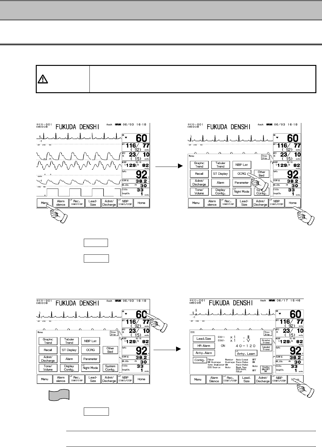
Touch Keys
All the operation is performed using the touch keys on the screen.
CAUTION Always operate the touch screen with fingers or touch screen pen. Do not
touch with a pen-point or other hard-edged instruments. Malfunction of the
touch screen or damage may result.
●General Key Control
1. Pressing the Menu key will switch the display with a pip sound.
2. The touch key will respond by pressing any part of the key.
3. Pressing the Home key at any time will return the display to the home display.
●Key Control for Each Parameter
1. The touch key will respond by pressing any part of the numeric display frame (parameter key).
2. Pressing the Home key at any time will return the display to the home display.
Reference
Up to 4 frequently used keys can be set as user key.
Refer to “4. Monitoring Setup To Set the User Keys” for details.
1
2
3
①
②
2−3
− Before Use − About the Home Display
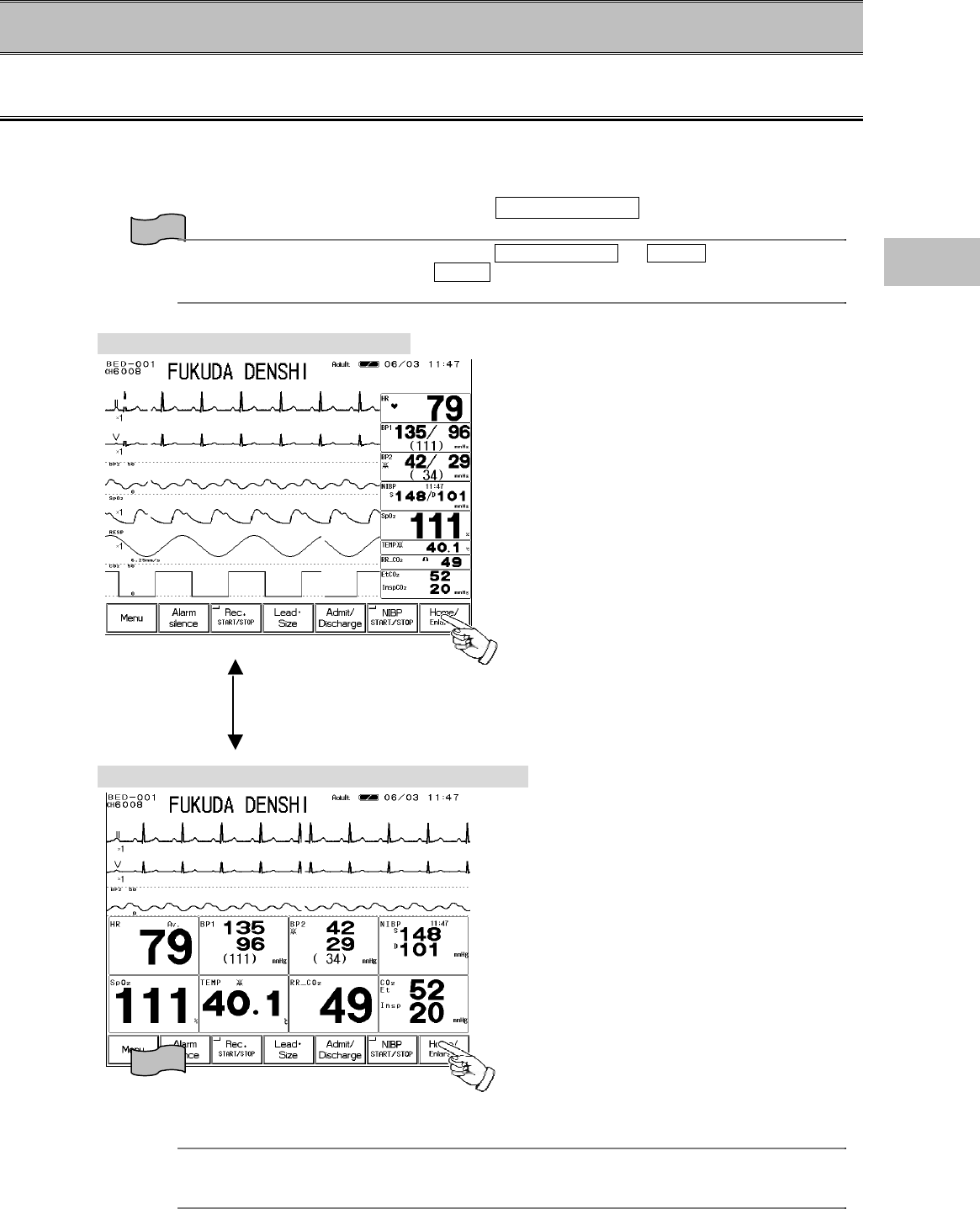
About the Home Display
?
The home display appears immediately after the power is turned ON.
?
The waveforms and numeric data are displayed on the home display.
?
There are 2 modes of home display, “Standard Display (Home)” and “Numeric Data Enlarged
Display”, which can be switched by pressing the Home / Enlarge key.
Reference
The home key function can be selected from Home / Enlarge or Home on the hospital
setup menu. The default setting is Home .
Refer to “8. System Configuration Hospital Setup” for details.
Standard Display (max. 6 waveforms)
This display is focused on number of
waveforms to be displayed.
Up to 6 waveforms can be displayed.
Numeric Data Enlarged Display (max. 3 waveforms)
This display is focused on the visuality of
numeric data. Each numeric data will be
displayed large for easier view.
Up to 3 waveforms will be displayed on the
upper half of the display.
Reference
The displaying waveforms and numeric data can be selected as desired, and the configured
display can be programmed.
Refer to “4. Monitoring Setup To Configure the Display” for details.
2
Before Use
2−4
The Description of the Display
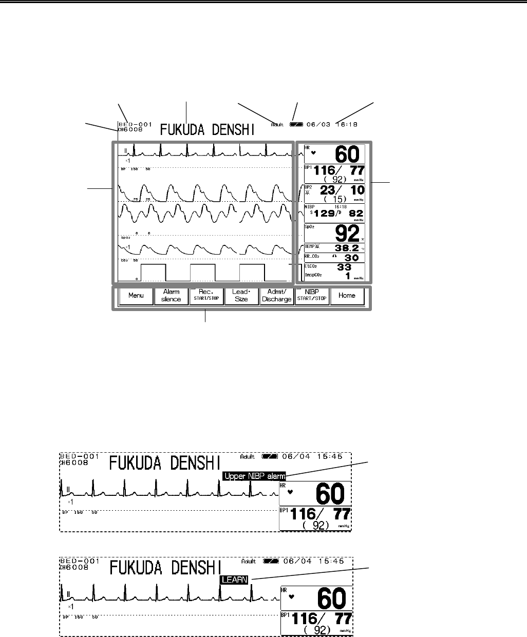
Other than waveforms and numeric data, patient name, alarm message, status message, etc. will
be displayed on the screen.
● Numeric Data, Waveform, Patient Name, etc.
●Alarm Message for Numeric Data / Arrhythmia
There are 2 types of alarm messages, numeric data alarm message and arrhythmia alarm
message. If both alarms occur at the same time, the numeric alarm message and arrhythmia
alarm message will be displayed alternately in 2-seconds intervals.
Bed ID Patient Name Patient Type Battery Capacity Time
Numeric Data Display Area
Parameter Key
Waveform Display
Area
Fixed Key, User Key
Numeric Data Alarm Message
Arrhythmia Alarm Message
Telemetry
Channel ID
2−5
●Equipment Status Alarm Message
The equipment status alarm message will be displayed when proper monitoring can not be
performed.
●Other Bed Alarm Message
When the monitor is connected to the network, and other bed alarm is turned ON, the alarm
occurring at the other bedside monitors will be notified.
The other bed alarm message will function as a control key. By pressing the message display,
the window to select the alarm generating bed will appear. Pressing the key will display the
numeric data and waveforms for that bed.
By pressing the Room/Bed ID key for the alarm
generating bed, the numeric data and
waveforms will be displayed.
The Room/Bed ID key for the alarm generating
bed will be indicated in red.
Reference
Refer to “7. Function Other Bed Display”
Equipment Status
Alarm Message
Other bed alarm
message
2
Before Use
2−6
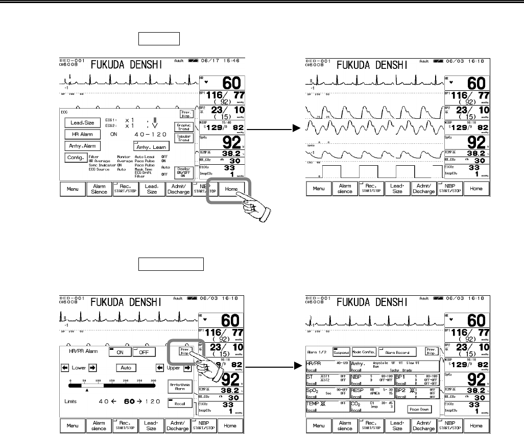
To Return the Display
【To Return to the Home Display】
By pressing the Home key, the display will return to the home display.
【To Return to the Previous Display】
By pressing the Prev. Disp. key which will be displayed on each setup window, the previous
display will appear.
2−7
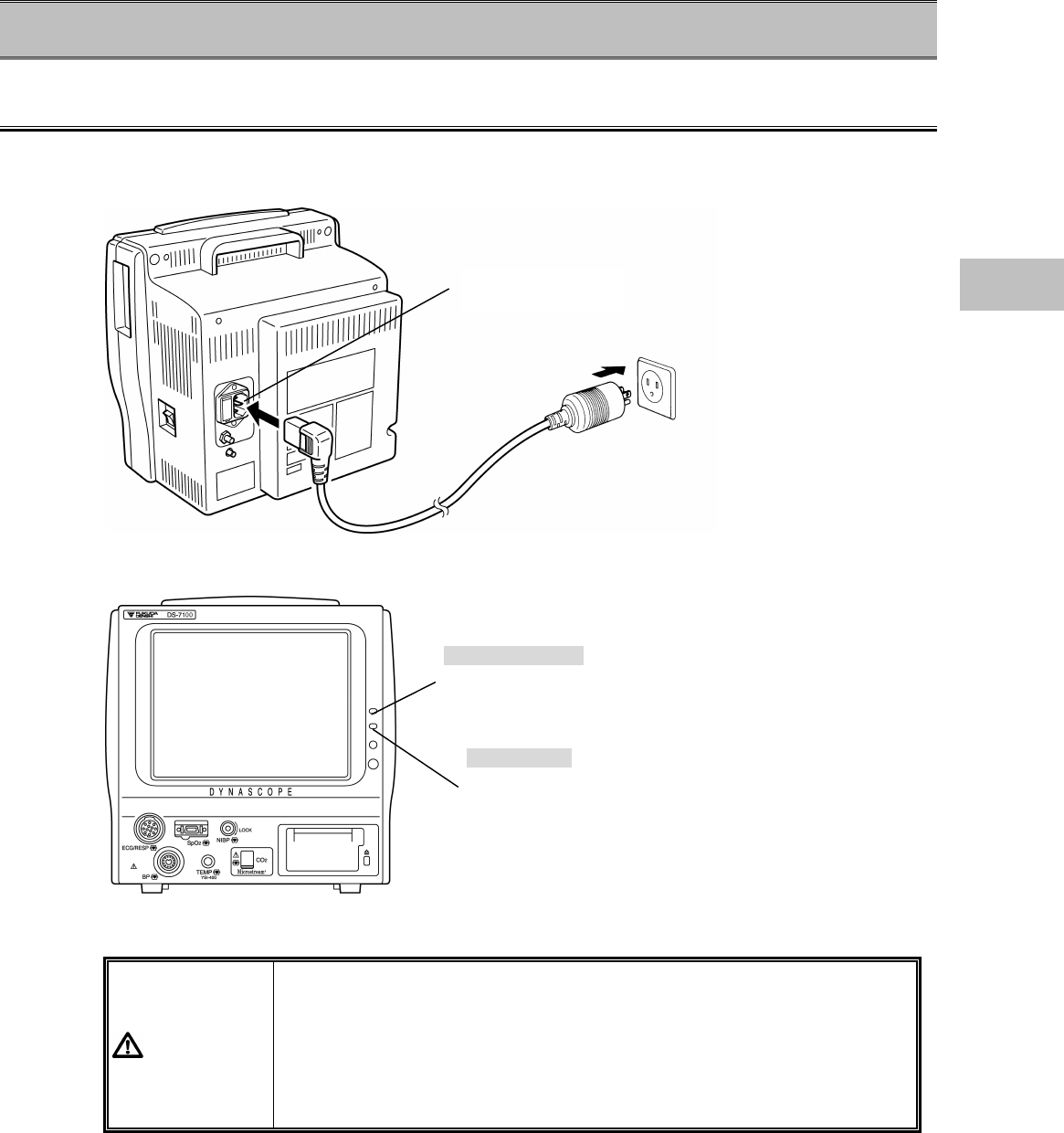
− Preparation for Monitoring −To Turn On the Power
Connecting the Power Cable
Connect the accompanying AC power cable (CS-34) to the monitor and to the 3-way grounded
outlet.
When the AC power is supplied to the monitor, the main power lamp will light in green.
When the battery pack (optional) is installed, the charge lamp will light and charging will start.
WARNING
?
Use only the accompanying 3-way AC power cable. Use of other
cables may result in electric shock to the patient and the operator.
?
The power cable must be connected to AC 115V hospital grade outlet.
?
When using multiple ME equipment simultaneously, perform
equipotential grounding to prevent potential difference between the
equipment. Even a small potential difference may result in electric
shock to the patient and the operator.
Power Supply
Connector
Charge Lamp
This lamp will light in orange during charging.
It will turn to green when the charging is complete.
Main Power Lamp
This lamp will light in green when the AC power is supplied.
The lamp will be extinguished during battery operation.
2
Preparation for Monitoring
2−8
NOTE
Equipotential Grounding
When connecting multiple devices, electrical potential difference may be
generated between the devices. This may result in electric shock to the patient
connected to these devices. Pay special attention for use in the operating room,
ICU, CCU, Cardiac Catheter Laboratory, and Cardiovascular X-ray room. To
avoid such electrical potential difference, use the accessory ground cable to
connect each device’s equipotential terminal to the same ground terminal. This
is called equipotential grounding.
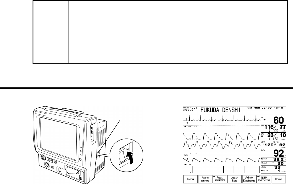
To Turn On the Power Switch
By turning the power switch ON, the display will appear and monitoring will start.
Power Switch
2−9
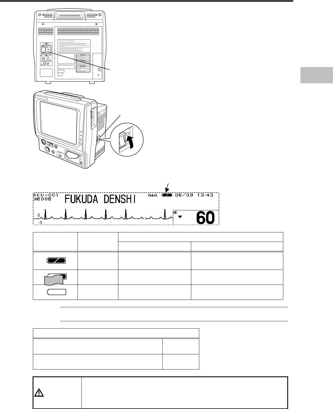
To Use with the Battery Pack
Unplug the power cable from the power supply
connector located at the rear side of the monitor.
If the power cable is unplugged with the power turned
ON, the monitor will also automatically change to
battery operation mode.
Turn ON the power switch located at the right side of
the monitor.
Indication of Operation Time
Battery Mark Charge
Condition Standard Mode Power Saving Mode
Full 3 hours∼2 hours 20 min. 3 hours 30 min.∼2 hours 40 min.
Medium 2 hours∼10 min. 2 hours 40 min.∼10 min.
Empty 10 min, 10 min.
Reference
Refer to “8. System Configuration Monitor Setup” for power saving mode.
Indication of Charging Time (Empty to Full)
When the power cable is connected and the
power is turned OFF 2.5 hours
When the power cable is connected and the
power is turned ON 13 hours
CAUTION
The above operation time indicates the time for the new battery pack
performing ECG measurement, NIBP periodic measurement (5-minute
interval). Note that the battery pack degrades with a continuous use and
shortens the usable time.
Power Supply
Connector
Power Supply Switch
During battery operation, a battery mark will be displayed on the
upper part of the display.
2
Preparation for Monitoring
2−10
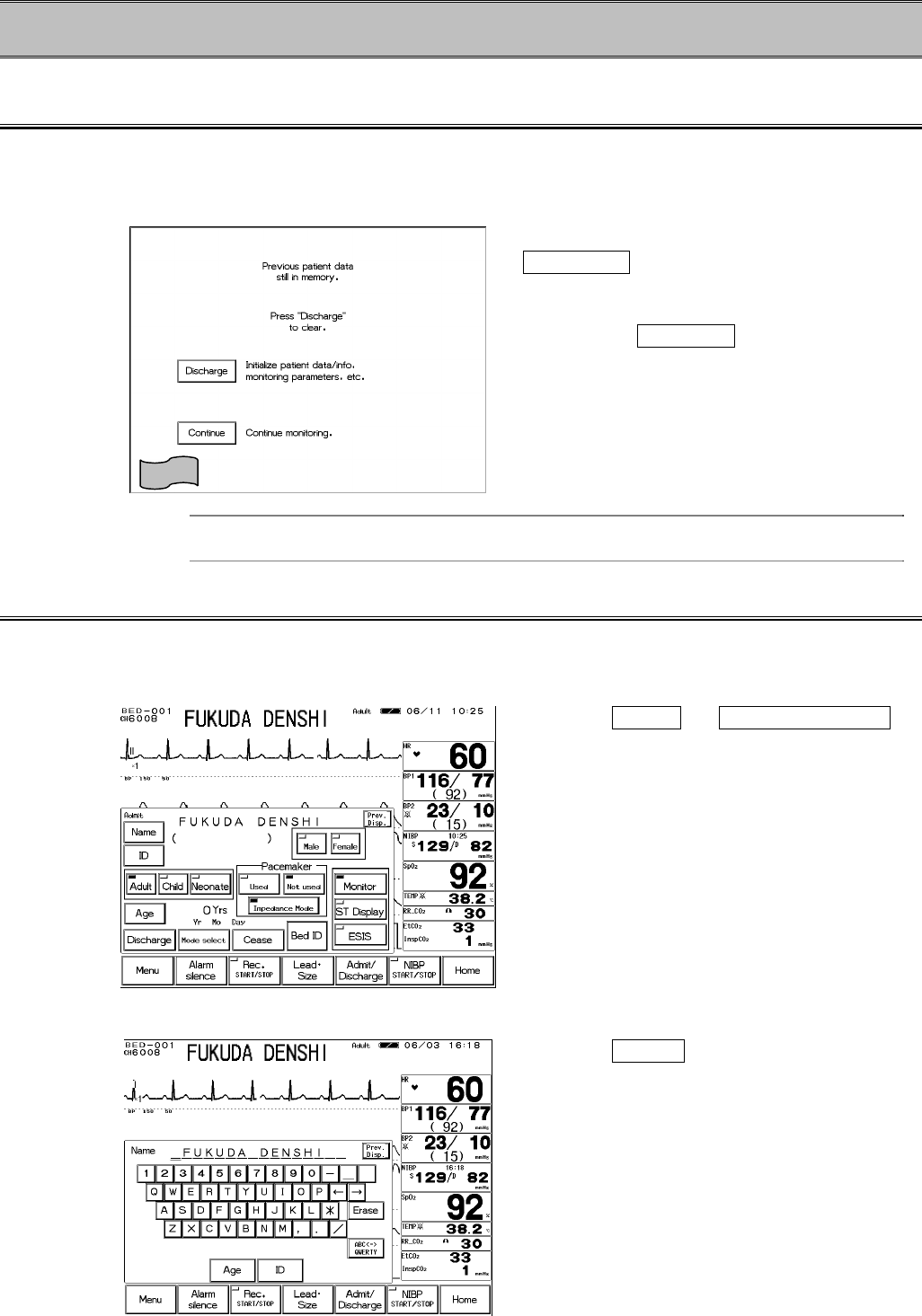
− To Start Monitoring −
Discharge Confirmation at Power ON
The monitor retains the trend and NIBP list data even when the power is turned OFF. If starting
to monitor a new patient, discharge procedure on the patient admit / discharge menu should be
performed.
To start monitoring a new patient, press the
Discharge key. The data before turning
ON the power will be erased and starts
monitoring.
Pressing the Continue key will retain the
data before turning ON the power and starts
monitoring.
Reference
ON/OFF of this confirmation display can be selected.
Refer to “8. System Configuration Monitor Setup” for details.
To Admit a Patient
Enter the patient information on the patient admit / discharge menu.
1. Open the patient admit / discharge menu.
Press the Menu → Admit / Discharge
key.
The patient admit / discharge menu will be
displayed.
2. Enter the patient name and ID.
Press the Name key.
Enter the name using the numeric keypad.
The entered name will be displayed large on
the upper part of the display.