Fukuda Denshi Co DS7100 Patient Monitor User Manual DS71v1 1 FA 10 Maintenance 012
Fukuda Denshi Co Ltd Patient Monitor DS71v1 1 FA 10 Maintenance 012
Contents
Manual 9

10−1
Maintenance
Chapter 10
− Handling − After Use / Display Panel ・・・・・ 2
Handling After Use ・・・・・・・・・・・・・・・・・・・・・・・・・・・ 2
Handling the Display Panel ・・・・・・・・・・・・・・・・・・・・ 2
− Storage −Device / Recording Paper ・・・・・・・・ 3
Storing the Device・・・・・・・・・・・・・・・・・・・・・・・・・・・・ 3
Storing the Recording Paper ・・・・・・・・・・・・・・・・・・・ 3
− Cleaning −Display Panel and Housing ・・・・・・ 4
Cleaning the Display Panel ・・・・・・・・・・・・・・・・・・・・ 4
Cleaning the Housing ・・・・・・・・・・・・・・・・・・・・・・・・・ 5
Disinfecting the Blood Pressure Transducers ・・・・・ 5
Disinfecting the Temperature Probes・・・・・・・・・・・・ 5
Disinfecting the CO2 Filter Line ・・・・・・・・・・・・・・・・・ 5
Cleaning and Disinfecting the SpO2 Transducer・・・ 5
Cleaning and Disinfecting the NIBP Cuff ・・・・・・・・・ 5
Cleaning and Disinfecting the ECG lead Cable ・・・ 5
− Battery −Handling the Battery Pack・・・・・ 6
Handling the Battery ・・・・・・・・・・・・・・・・・・・・・・・・・・ 6
Storing the Battery・・・・・・・・・・・・・・・・・・・・・・・・・・・・ 6
− Maintenance Check −Daily and Periodic Check ・7
About the Maintenance Check ・・・・・・・・・・・・・・・・・ 7
●Daily Check ・・・・・・・・・・・・・・・・・・・・・・・・・・・・・・・7
●Periodic Check ・・・・・・・・・・・・・・・・・・・・・・・・・・・・7
Time-Change Components ・・・・・・・・・・・・・・・・・・・・ 7
− Troubleshooting −・・・・・・・・・・・・・・・・・・・・・・・・・・・ 9
ECG・・・・・・・・・・・・・・・・・・・・・・・・・・・・・・・・・・・・・・・・ 9
Respiration ・・・・・・・・・・・・・・・・・・・・・・・・・・・・・・・・・11
Invasive Blood Pressure・・・・・・・・・・・・・・・・・・・・・・ 11
SpO2・・・・・・・・・・・・・・・・・・・・・・・・・・・・・・・・・・・・・・12
Non-Invasive Blood Pressure ・・・・・・・・・・・・・・・・・13
Temperature・・・・・・・・・・・・・・・・・・・・・・・・・・・・・・・・14
CO2 Concentration・・・・・・・・・・・・・・・・・・・・・・・・・・・15
Recorder ・・・・・・・・・・・・・・・・・・・・・・・・・・・・・・・・・・・16
Telemetry ・・・・・・・・・・・・・・・・・・・・・・・・・・・・・・・・・・16
General ・・・・・・・・・・・・・・・・・・・・・・・・・・・・・・・・・・・・17
Battery・・・・・・・・・・・・・・・・・・・・・・・・・・・・・・・・・・・・・ 18
10
Maintenance

10−2
− Handling − After Use / Display Panel
This section describes precautions for handling the equipment.
Handling After Use
?
Do not apply excessive force when disconnecting the cables. Always pull on the connector
housing and not on the cable.
?
Clean the unit, accessories, and cables, and keep them together in one place for next use.
?
Always check for adequate supply of disposable accessories such as ECG electrodes. If any
shortage, contact our service representative and supply as necessary.
Handling the Display Panel
?
The display panel utilizes exclusive fluorescent light for the backlight.
As this fluorescent light tube has product life cycle, it needs to be replaced periodically. If the
display becomes dark, scintillates, or does not light, contact your nearest service representative.
?
The LCD used for the display panel utilizes highly accurate picture elements of pixels over
99.99%, but there may be an absence (less than 0.01%) or constant lighting of pixels.

10−3
− Storage −Device / Recording Paper
This section describes about the storage of the device and recording paper.
Storing the Device
?
Store in a place where the device will not be exposed to splashing water.
?
Store in a place where the device will not be adversely affected by atmospheric pressure,
temperature, humidity, ventilation, sunlight, dust or atmosphere containing salt or sulfur.
?
Store in a level area where the device is not exposed to vibration and shock (including during
transportation).
?
The following environmental conditions should be observed when storing the device.
Storage Temperature :−10∼60?C
Storage Humidity :10∼95% (at 60?C)
Storing the Recording Paper
The DS-7100 system utilizes heat sensitive recording paper. If placed in a high temperature for
long period of time, the print may become indistinct, and unable to read. When storing, follow the
precautions below.
?
Store in a place where light is shut off and avoid direct sunlight.
?
Do not leave the paper in a high temperature (50 °C or 122 °F or above).
?
Do not store the paper in polyvinyl chloride bag.
?
Do not expose the paper to alcohol, hydrochloric acid, or ester ketone.
?
Avoid using adhesive agents other than water based glue.
10
Storage
10−4
− Cleaning −Display Panel and Housing
This chapter explains about the cleaning of the device and sensors.
Cleaning the Display Panel
Since this device incorporates a touch screen, finger prints and other stains are likely to appear on
the display panel.
Follow the procedure below to clean the display panel.
1. Press the Key Lock key for more than 2 seconds.
Reference
The Key Lock key needs to be preprogrammed as user key.
Refer to ” 8. System Configuration Ward Setup” for user key setup.
2. Clean the touch panel.
While the “Touch key OFF" message is displayed, the touch panel key will be deactivated.
If “LEAD OFF” or other message is displayed, the key lock message will not be displayed.
3. Wipe the touch panel using cleaning cloth.
4. Press again the Key Lock key for more than 2 seconds.
The message will disappear and the keys will be activate again.
CAUTION
?
Do not clean the touch panel using strong acid.
?
A special coating is applied to the surface of the touch panel. Wipe the
surface with the soft cleaning cloth provided as optional accessory or
with commercially available eyeglass cleaning cloth.
10−5
Cleaning the Housing
Clean the housing using tightly squeezed gauze or an absorbent cotton cloth dampened with
alcohol or a neutral cleanser.
CAUTION
?
Clean the equipment frequently so stains can be removed easily.
?
To prevent injury, it is recommended to wear gloves when cleaning the
equipment.
?
Do not allow liquids or cleaning solution to enter the monitor or
connectors.
?
Do not use organic solvents, thinner, toluene and benzene to avoid
damaging the resin case.
?
Do not polish the housing with abrasive or chemical cleaner.
?
When sterilizing the entire room using a spray solution, pay close
attention not to have liquids get into the monitor or connectors.
?
Use only neutral detergent to clean the housing. Do not use chemical
cloth, scrub brush, abrasive, polishing powder, hot water, volatile
solvent and chemicals (cleanser, thinner, benzine, benzol, and
synthetic detergent for house and furniture), or sharp-edged tools.
The surface resin coating may be damaged, resulting in discoloration,
scratches, and other problems.
Disinfecting the Blood Pressure Transducers
Disinfect the blood pressure transducers according to the manufacturer’s guidelines.
Disinfecting the Temperature Probes
Disinfect the Temperature Probes according to the manufacturer’s guidelines.
Disinfecting the CO2 Filter Line
Disinfect the Filter Line/Capno Line according to the manufacturer’s guidelines.
Cleaning and Disinfecting the SpO2 Transducer
?
Do not soak the sensor in water or antiseptic solution.
?
Wipe the DURASENSOR with disinfectant such as 70% alcohol. Do not disinfect by applying
radioactive rays, steam, or ethylene oxide.
?
OXISENSOR is a disposable sensor. Do not reuse or attempt resterilization.
Cleaning and Disinfecting the NIBP Cuff
?
Do not soak the sensor in water or antiseptic solution.
?
Wipe the NIBP cuff with disinfectant such as 70% alcohol. Do not disinfect by applying
radioactive rays, steam, or ethylene oxide.
Cleaning and Disinfecting the ECG lead Cable
?
Do not soak the sensor in water or antiseptic solution.
?
Wipe the ECG lead cable with disinfectant such as 70% alcohol. Do not disinfect by applying
radioactive rays, steam, or ethylene oxide.
10
Cleaning
10
Cleaning
10
Cleaning
10−6
− Battery −Handling the Battery Pack
This section describes about the handling and storage of the battery pack.
Handling the Battery
?
The battery pack can be continually used for more than 300 times (or about 1 year) under normal
temperature, but the continuous use will degrade the battery and shortens the usable time.
?
When the battery operation time becomes short even after it is fully charged, the battery pack
needs to be replaced.
?
When the charge time of the battery pack becomes short, the battery pack needs to be replaced.
?
When the battery pack level becomes low, charge the battery well in advance for the next use.
Storing the Battery
To take advantage of the characteristic of battery pack, pay attention to the following when storing.
Storage Temperature and Humidity
?
Store in an environment specified below without corrosive gas.
Storage Period Storage
Temperature Storage
Humidity
Within 30days −20∼60?C
30 days∼90 days −20∼45?C
90 days∼1year −20∼35?C
65?20%
?
Do not store in an environment outside the specified temperature range or excessive high
humidity. This may result in leakage caused by expansion/contraction inside the battery pack,
or rusting of the metal part.
Long-term Storage
?
If left installed in the monitor for long period of time, the electrolyte may leak, or inactivate the
battery which degrades the capacity recovery after storage. Therefore, always remove the
battery from the monitor when storing for long period of time. Contact our service
representative when removing the battery.
10−7
− Maintenance Check −Daily and Periodic Check
This section explains the daily check and periodic check items of the device.
About the Maintenance Check
Periodic inspection must be performed. When reusing the device which was left unused for a
while, always check that the device operates properly and safely before use.
To ensure safety, reliability, and high performance, a “Daily Check” and “Periodic Inspection” must
be performed. We are not liable for any accident arising from lack of maintenance.
CAUTION ?
Do not open the housing of this device.
?
Avoid alcohol or other liquids from getting into the equipment.
●Daily Check
Perform daily inspection using the “Daily Check List” on the next page.
●Periodic Check
Periodic inspection of medical electronic equipment is mandatory to prevent failures and accidents
and to ensure safety and reliability.
Periodic maintenance may be performed by each medical institution or by a third party by
concluding a “Maintenance Contract”.
For more details, contact your nearest service representative.
Time-Change Components
To ensure reliability of safety, function, and performance of this device, the time-change
components must be replaced periodically. When replacing, contact our service representative.
EtCO2 Unit Replacing Period: 7,000 hours (approx. 10 months of
continuous use)
LCD Unit, Inverter Unit Replacing Period: 50,000 hours or 6 years
NIBP Unit Replacing Period: 100,000 times of use or 6 years
Short Term Backup Battery Replacing Period: 4 years∼6 years according to the used
frequency
Long Term Backup Battery Replacing Period: 6 years
Battery Pack Replacing Period: 1 year or 300 times of charging /
discharging.
CAUTION The time-change components must be replaced at specified period.
10
Maintenance Check

10−8
Daily Check List
No.
Inspected Date Inspected by Location
Device Type Serial No. Date of Purchase
Item Details Criteria Judgement
Appearance Visually check the exterior for
scratches, cracks, deformation,
and rust.
No abnormality should be
found. □OK / □NG
Check whether the unit is
installed on a level surface.
The installation area must be
level and free from vibration
and shock. □OK / □NG
Installation Check whether the unit is
installed in a place susceptible to
adverse environment.
The environmental condition
(ex. temperature, humidity) of
the installed place should be
as specified.
The unit should not be
subjected to splashing water.
□OK / □NG
The home display appears,
and the lamp located at the
right side of the display panel
lights.
□OK / □NG
Functions Turn ON the monitor, and check
whether it operates normally.
The date and time should be
correct. □OK / □NG
Cables Visually check all cables for any
damage. No damage should be found. □OK / □NG
Periodic Inspection Check the date of previous
periodic inspection. Should be within 1 year. □OK / □NG
CO2 Calibration
(DS-7141)
Check the date of previous
calibration date.
Previous Date
Day Year Month
Should be within 6 months. □OK / □NG
Comment

10−9
− Troubleshooting −
This section explains the troubleshooting for each case.
ECG
The “LEAD OFF” message is displayed.
Cause :The electrode is detached, or is not making good electrical contact with the skin.
Solution :・Check if the electrodes are properly attached.
・Replace the electrode, or check the lead cable.
The “ECG failed” message is displayed.
Cause 1 :The ECG amplitude is 0.25mV or below for the waveform size of ×1, ×1/2, ×1/4,
and 0.150mV or below for the waveform size of ×2, ×4.
Solution :Change the electrode attachment site, or select the lead with higher QRS amplitude.
Note :Using 4-electrode or 5-electrode instead of 3-electrode allows more accurate QRS
detection.
Cause 2 :The electrode contact is poor.
Electrical blanket or other noise source is near the patient.
Solution :Attach the electrode firmly.
・Replace the lead cable if defective.
・If any noise source is near the patient, locate it away from the patient as much as
possible.
ECG waveform contains noise.
The “Artifact” message is displayed.
Cause 1 :The electrode contact is poor.
Electrical blanket or other noise source is near the patient.
Solution :Attach the electrodes firmly.
・Replace the lead cable if defective.
・If any noise source is near the patient, locate it away from the patient as much as
possible.
Cause 2 :EMG is interfering.
Solution :・Change the electrode site to a location where EMG will less likely to interfere.
・Select ESIS mode for the filter mode.
Note :Selecting a ESIS mode for the filter mode will decrease the QRS amplitude and may
result in not counting the heart rate.
The “Check electrode” message is displayed.
Cause :The electrode contact with the skin is poor. There is substantial contact resistance
between the electrodes.
Solution :Replace all the electrodes.
Use the electrodes of the same type.
The “ECG unit error” message is displayed.
Cause :A communication error with the ECG measuring unit exists.
Solution :The breakage of wire or failure of the ECG unit can be considered.
Contact our service representative.
10
Troubleshooting

10−10
The measured data is displayed as “×××”.
Cause :The heart rate is outside the measurement range.
Solution :・Check the electrode application.
・Replace the electrode, or check the lead cable.
Heart rate is not counted. Heart rate is low.
Cause :The ECG waveform amplitude is below the QRS detection level (0.3mV).
Solution :Change the electrode site, or select a lead with higher QRS amplitude.
Note :Using 4-electrode or 5-electrode instead of 3-electrode allows more accurate QRS
detection.
Also, if large amount of noise is interfering, the noise may be erroneously detected as
QRS. It is recommended to change the electrode site and increase the ECG
amplitude.
Heart rate is not counted, and “LEAD OFF” message is displayed.
Cause :The electrode of the displayed lead type is detached, or is not making good electrical
contact with the skin.
Solution :・Check the electrode application.
・Replace the electrode, or check the lead cable.
Artificial pacemaker is not displayed.
Cause :On the admit / discharge menu, Not used is selected for the pacemaker use.
Solution :Select Used for the pacemaker use.
The “Pacemaker error” message is displayed.
Cause :The pacemaker pulse is detected 16 pulses or more per second.
Solution 1 :Attach the electrodes firmly.
・Replace the lead cable if defective.
・If any noise source is near the patient, locate it away from the patient as much as
possible.
Solution 2 :If the patient is not wearing a pacemaker, set to Not used for the pacemaker use
in the patient admit/discharge menu.
The “ECG not connected” message is displayed.
Cause :When the ECG relay cable is disconnected during ECG monitoring, this message will
be displayed.
Solution 1 :To cease monitoring, press the Alarm Silence key to clear the message and
silence the alarm.
Solution 2 :To continue monitoring, plug in the ECG relay cable. This will clear the message and
silence the alarm.
10−11
Respiration
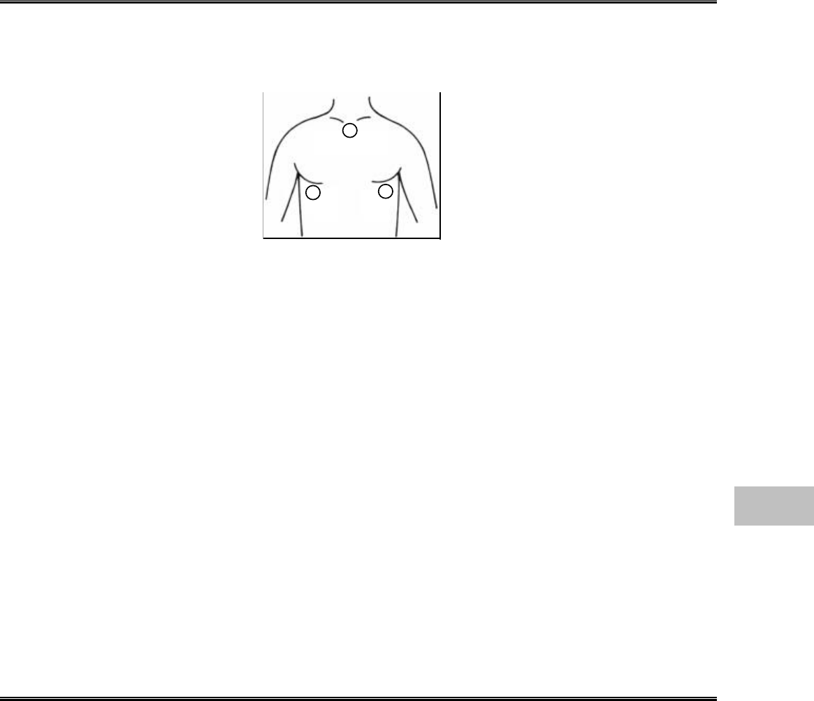
The “CVA detected” message is displayed.
Cause :Heartbeat is interfering and superimposed on the respiration waveform.
Solution :Place the electrode as shown below where the heartbeat will be less likely to interfere.
“0” is displayed for respiration rate, or apnea alarm is generated.
Cause :The respiration waveform amplitude is below the detection level (0.2O).
Solution :Change the electrode site.
The respiration waveform and respiration rate is not displayed.
Cause 1 :The ECG relay cable designed for electrosurgical knife is used.
Solution :The impedance respiration can not be measured if the cable designed for
electrosurgical knife is used. Use the standard ECG relay cable if not using the
electrosurgical knife.
Cause 2 :The impedance respiration measurement is ceased.
Solution :Turn ON the impedance respiration measurement on the admit / discharge menu or
RESP configuration menu.
Note :If the pacemaker with the minute ventilation measuring function is used, turn OFF the
impedance respiration measurement. Otherwise, both the pacemaker and the monitor
will not be able to perform accurate measurement.
The measured data is displayed as “×××”.
Cause :The respiration rate is outside the measurement range.
Solution :・Check the electrode application.
・Replace the electrode, or check the lead cable.
Invasive Blood Pressure
The “BP1 Transducer OFF”, “BP2 Transducer OFF” message is displayed.
Cause :The transducer for BP1 or BP2 is not connected.
Solution :Connect the transducer.
The “BP1 not zero balanced”, “BP2 not zero balanced” message is displayed.
Cause :The BP zero balance has not been performed since the power is turned ON.
Solution :Open the three-way cock of the transducer to air and perform zero balance.
The measured data is displayed as “ー ー ー”.
Cause :The BP zero balance has not been performed since the power is turned ON.
Solution :Open the three-way cock of the transducer to air and perform zero balance.
10
Troubleshooting
Red
White Black

10−12
BP value and waveform are not displayed properly.
Cause :Blood pressure line has not been zero balanced.
Solution :Open the three-way cock of the transducer to air and perform zero balance.
The measured data is displayed as “×××”.
Cause :The BP value is outside the measurement range.
Solution :Perform zero balance again.
The “BP not connected” message is displayed.
Cause :When the BP interface cable or 2ch BP conversion cable is disconnected during BP
monitoring, this message will be displayed.
Solution 1 :To cease monitoring, press the Alarm Silence key to clear the message and
silence the alarm.
Solution 2 :To continue monitoring, plug in the BP interface cable or 2ch BP conversion cable.
This will clear the message and silence the alarm.
The “Incorr. BP cable” message is displayed.
Cause :The cable other than 2ch BP conversion cable is plugged in to the BP connector.
Solution :Use the 2ch BP conversion cable.
SpO2
The “Check SpO2 sensor” message is displayed.
Cause :Sensor is detached from the patient.
Solution 1 :Check if the sensor part is properly attached to the patient.
Solution 2 :Check if the light emitting part and light receiving part of the sensor LED is aligned.
The “Pulse search” message is displayed.
Cause :The amplitude of the pulse waveform is low, or the sensor is not positioned correctly.
Solution :Check if the light emitting part and light receiving part of the sensor LED is aligned.
The “No pulse detect” message is displayed.
Cause :The amplitude of the pulse waveform is low, or the sensor is not positioned correctly.
Solution :Check if the light emitting part and light receiving part of the sensor LED is aligned.
The “Motion Artifact” message is displayed.
Cause :There is excessive body motion of the patient.
Solution :Change the sensor position where the body motion will have less effect.
The pulse waveform is not displayed, or interrupted
Situation :“Check SpO2 sensor” is displayed.
Cause 1 :The amplitude of the pulse waveform is low, or the sensor is not positioned correctly.
Solution :Check if the light emitting part and light receiving part of the sensor LED is aligned.
Cause 2 :Sensor is defective.
Solution :Replace the sensor.
Cause 3 :SpO2 sensor is not firmly connected to the SpO2 input connector.
Solution :Make sure the SpO2 sensor is securely connected.
Cause 4 :Sensor is exposed to light.
Solution :Place a black or dark cloth over the sensor to avoid direct sunlight. Also when not
used, avoid placing the sensor in light or unplug the sensor from the connector.

10−13
The SpO2 measurement is unstable.
Cause :There is excessive body motion of the patient which disables correct measurement.
Solution :1. Have the patient lie still as much as possible.
2. Relocate the sensor, or change the sensor to which the body motion will have less
influence.
The “SpO2 unit error” message is displayed.
Cause 1 :There is a failure of communication with the SpO2 measurement unit.
Solution :Breaking of wire or SpO2 unit failure can be considered.
Contact our service representative.
Cause 2 :Sensor is defective.
Solution :Replace the sensor.
The “SpO2 sensor fault” message is displayed.
Cause :Sensor is defective.
Solution :Replace the sensor.
The “SpO2 not connected” message is displayed.
Cause :When the SpO2 relay cable is disconnected during SpO2 monitoring, this message will
be displayed.
Solution 1 :To cease monitoring, press the Alarm Silence key to clear the message and
silence the alarm.
Solution 2 :To continue monitoring, plug in the SpO2 relay cable. This will clear the message
and silence the alarm.
Non-Invasive Blood Pressure
The cuff is not inflated although the pump is operating.
Cause1 :The air hose is not firmly connected, and the air is leaking.
Solution :Check if the air hose is properly connected.
Cause 2 :The cuff size is not corresponded to the selected patient type.
Solution :Check if the cuff size is corresponded to the selected patient type.
The monitor repeats the measurement, or “ー ー ー” is displayed for the numeric data.
Cause 1 :The measurement accuracy is not reliable due to body motion artifact.
Solution :Have the patient stay still as much as possible during the measurement.
Cause 2 :The pulse is too small to acquire reliable measurement accuracy.
Solution :Check if the cuff application is proper, and if the cuff size is corresponded to the
selected patient type.
The “Check NIBP hose” message is displayed.
Cause :The applied pressure to the cuff has exceeded the maximum limit. The measurement
time has exceeded the maximum limit.
Solution :Check if the cuff application is proper, if the cuff size is corresponded to the selected
patient type, or if the air hose is not bent. After checking the above, perform the
measurement again.
If the same message is displayed again, a failure of the equipment can be considered.
Cease the measurement, and contact our service representative.
10
Troubleshooting

10−14
The “NIBP unit error” message is displayed.
Cause :The zero balancing before the measurement has failed, and measurement could not be
started.
Solution :The body movement or other artifact may cause zero balance failure. During the
measurement, have the patient stay still as much as possible.
If the same message is displayed again, the failure of the equipment can be considered.
Cease the measurement, and contact our service representative.
The time of measurement disappears and the numeric data is displayed as “ー ー ー”.
Cause :The NIBP data will be erased when the preprogrammed NIBP erase time has elapsed.
Solution :Select the appropriate time for NIBP data erase time from 10min, 30min, 60min, 24hrs
which best fits the monitoring purpose.
Temperature
The “Wrong Temp Probe” message is displayed.
Cause 1 :The YSI-700 is used.
Solution :Use the YSI-400 temperature probe for measurement. The YSI-700 can not be used
with the DS-7100 series.
Cause 2 :There is a contact failure of the temperature probe.
Solution :Check if the temperature probe is properly inserted.
The numeric data is displayed as “×××”.
Cause :The temperature measurement is outside the measurement range.
Solution :Check if the temperature probe is properly inserted.
The “TEMP not connected” message is displayed.
Cause : When the temperature sensor is disconnected during temperature monitoring, this
message will be displayed.
Solution 1 :To cease monitoring, press the Alarm Silence key to clear the message and
silence the alarm.
Solution 2 :To continue monitoring, plug in the temperature sensor. This will clear the message
and silence the alarm.
The “TEMP auto check” message is displayed. The numeric data is displayed as “ー ー ー”.
Cause :The temperature is calibrated once every hour on this monitor. During calibration, the
numeric data will be displayed as “ー ー ー”.
Solution :The calibration will complete in 10 seconds. If the calibration does not complete within
10 seconds, cease the measurement and contact our service representative.
The “TEMP unit check” message is displayed.
Cause :Error is detected during temperature calibration.
Solution :A unit failure can be considered. Cease the measurement and contact our service
representative.

10−15
CO2 Concentration
The “Check filter line” message is displayed.
Cause :The sampling tube is clogged.
Solution :Replace the sampling tube.
The “Self-diag CO2” message remains displayed.
Cause :An error has occurred to the self-check procedure at power ON.
Solution :The CO2 unit failure can be considered.
The “Initializing CO2” message does not disappear.
Cause :An error has occurred during the initialization at power ON.
Solution :The CO2 unit failure can be considered.
The “Check CO2 unit” message is displayed.
Cause 1 :The exhaust connector is clogged.
Solution :After checking the exhaust system and removing the clog, press the “Restart CO2” key
on the CO2 configuration menu.
Cause 2 :The sampling tube or nasal prong is clogged.
Solution :After checking the inhalation system and removing the clog, press the “Restart CO2”
key on the CO2 configuration menu.
Cause 3 :The CO2 unit needs to be replaced.
Solution :Contact our service representative.
The “CO2 unit error” message is displayed.
Cause :There is a communication error with the CO2 unit.
Solution :The break of wire or CO2 unit failure can be considered.
Contact our service representative.
There is substantial measurement error.
Cause 1 :20 minutes have not yet elapsed since the power is turned ON.
Solution :For 20 minutes from turning ON the power, there will be a substantial measurement
error.
Cause 2 :The calibration is not properly performed.
Solution :Perform CO2 calibration again.
The “CO2 not connected” message is displayed.
Cause :When the filter line is disconnected during CO2 monitoring, this message will be
displayed.
Solution 1 :To cease monitoring, press the Alarm Silence key to clear the message and
silence the alarm.
Solution 2 :To continue monitoring, plug in the filter line. This will clear the message and silence
the alarm.
10
Troubleshooting

10−16
Recorder
No recording is performed.
Situation :The “Paper Out” message is displayed on the upper left of the screen.
The “Paper Out” message is displayed on the Rec. START/STOP key.
Cause :There is no recording paper in the recorder magazine.
Solution :Install a new pad of paper into the paper magazine.
Situation :The “Magazine Open” message is displayed.
Cause :The paper magazine is open.
Solution :Close the magazine.
Situation :The “Paper jammed” message is displayed.
Cause :The paper is jammed.
Solution :Open the magazine and install the paper correctly.
Situation :No message is displayed, but recording can not be performed.
Cause :The recording paper is not correctly installed. The front and backside of the paper is
set oppositely.
Solution :The “END” printed side of the paper should be facing down in the magazine.
The second waveform and third waveform are not recorded.
Situation :The second waveform and third waveform are not recorded for manual recording or
alarm recording.
Cause :The second waveform and third waveform are not set on the recording setup menu.
Solution :Set the second waveform and the third waveform on each recording setup menu.
The “Recorder error” message is displayed.
Cause :The thermal head temperature has increased.
Solution :A damage to the thermal head can be considered.
Contact our service representative.
Telemetry
The “Telemetry unit error” message is displayed.
Cause :There is a communication error with the telemetry transmission unit.
Solution :The breaking of wire or telemetry transmission unit failure can be considered.
Contact our service representative.
There is no reception at the telemetry center.
Cause :The channel ID or group ID is not corresponded with the telemetry receiver.
Solution :Set the correct channel ID and group ID.
The BP waveform of 100mmHg or above can not be properly received.
Cause :The BP waveform and scale is not corresponded.
Solution :When BP waveform is above 100mmHg, set the BP scale above 100mmHg.

10−17
General
Nothing is displayed but the main power indicator is lighted.
Cause :A system error has occurred.
Solution :Turn off the power, unplug the power cable, and contact our service representative.
The “Adjusting” message is displayed. Numbers are displayed large on the display.
Cause :This is the test mode. Stop using the device immediately.
Solution :Restart the system. The test mode will be cancelled.
If the same situation is observed again, contact our service representative.
Turn off the DIP switch No.1.
The data is initialized each time the power is turned ON.
Cause 1 :The internal switch is set to initialize.
Solution :The internal switch setting needs to be changed. Contact our service representative.
Set the rotary switch to 0.
Cause 2 :The battery for backup memory is depleted.
Solution :The battery needs to be replaced. Contact our service representative.
The display is not clear.
Cause 1 :The display brightness is not adjusted.
Solution :Due to the LCD display characteristic, the visible range is limited. Adjust to the
appropriate brightness.
Cause 2 :The monitor is set to the night mode.
Solution :Cancel the night mode.
The system does not start although the power switch is turned ON.
Cause 1 :The power cable is not connected.
The battery is not charged.
Solution :Turn off the power and connect the power cable. If the battery is not charged, use the
power cable until the battery charging is complete.
Cause 2 :Incorrect IC card is inserted.
Solution :Turn off the DIP switch No.8.
The clock is often delayed.
Cause :The battery for the backup memory is depleted. Check if the time is delayed when the
power is turned off.
Solution :The battery needs to be replaced. Contact our service representative.
10
Troubleshooting

10−18
Battery
The operation time is short although the battery is charged.
Cause 1 :The battery life has expired.
Solution :The battery pack is a consumable product. Replace it once a year.
Cause 2 :The ambient temperature is too high or too low.
Solution :For safety, the charging operation will be in a standby mode when the battery pack
temperature becomes excessively high or low.
The charging will automatically resume when appropriate temperature is reached.
Charge the battery in an ambient temperature of 10∼30?C.
The charge lamp on the patient monitor does not light.
Cause 1 :The AC power cable is disconnected.
Solution :Plug in the AC power cable.
The battery pack can be charged only during the AC operation.
Cause 2 :The battery pack is not installed.
Solution :The battery pack is optional. If a battery pack is required, contact our service
representative and install the battery pack.
Cause 3 :The battery life has expired.
Solution :The battery pack is a consumable product. Replace it once a year.
During the charging procedure, the charge lamp (orange) does not switch to charge
complete status (green) and extinguishes.
Cause 1 :The battery pack temperature is too high or too low.
Solution :For safety, the charging operation will be in a standby mode when the battery pack
temperature becomes excessively high or low.
The charging will automatically resume when appropriate temperature is reached.
Cause 2 :The breakdown of battery pack can be considered.
Solution :If the charging operation does not complete within the specified charging time, the
charging operation will cease for safety purpose.
Contact our service representative and replace the battery pack.
Cause 3 :The battery life has expired.
Solution :The battery pack is a consumable product. Replace it once a year.
The “Charge battery” message is displayed.
Cause :The AC power cable is disconnected.
Solution :Plug in the AC power cable.
The battery pack can be charged only during the AC operation.

11−1
Technical Information
Chapter 11
− Specification/Performance −・・・・・・・・・・・・・・・・・・ 2
Specification・・・・・・・・・・・・・・・・・・・・・・・・・・・・・・・・・ 2
Performance・・・・・・・・・・・・・・・・・・・・・・・・・・・・・・・・・ 3
− Setup Item −Default and Backup・・・・・・・・・・・ 5
Patient Admit / Discharge・・・・・・・・・・・・・・・・・・・・・・ 5
Alarm Setup ・・・・・・・・・・・・・・・・・・・・・・・・・・・・・・・・・ 5
Parameter Setup ・・・・・・・・・・・・・・・・・・・・・・・・・・・・・ 6
Review Function Setup・・・・・・・・・・・・・・・・・・・・・・・・ 7
System Configuration Setup ・・・・・・・・・・・・・・・・・・・ 8
Display Mode Setup ・・・・・・・・・・・・・・・・・・・・・・・・・12
Alarm Mode Setup・・・・・・・・・・・・・・・・・・・・・・・・・・・13
− External Connection −Pin Assignments・・・14
Serial Connector Output Signal・・・・・・・・・・・・・・・・14
Status I/O Signal ・・・・・・・・・・・・・・・・・・・・・・・・・・・・ 14
11
Technical Information

11−2
− Specification/Performance −
This section states the specification and performance of this equipment.
Specification
Size
260 (W) ×197 (D) ×264 (H) mm (not including the protrusion)
Weight (not including the battery)
DS-7141 :5.3kg
DS-7101L :5.1kg
DS-7101LT :5.2kg
Environmental Condition
Operating Temperature :10∼40?C
Operating Humidity :30∼85% (without condensation)
Transport / Storage Temperature :−10∼60?C
Transport / Storage Temperature :10∼95% (at 60?C)
Safety
General Standard :EN60601-1:1990
(Medical electrical equipment – Part 1: General requirements for
safety)
Amendment A1 to EN 60601-1:1993
Amendment A2 to EN 60601-1:1995
EMC Standard : IEC 60601-1-2:1993
(Medical electrical equipment−Part 1: General requirements for safety
−2.Collateral standard:
Electromagnetic compatibility −requirements and
tests. IEC 601-1-2:1993 )
Withstand Voltage :Class I, Type CF
Power Requirements
Voltage AC100∼240V ?10% DC14V ?10%
Frequency 50/60Hz ?
Power
Consumption 82VA 60W

11−3
Performance
Display
Device :8.4 inch TFT Color LCD
Control :Touch Screen Type
Waveform Trace :Stationary Trace
Waveform Speed :ECG / SpO2 / BP (6.25mm/s, 12.5mm/s, 25mm/s)
RESP / CO2 (6.25mm/s, 12.5mm/s, 25mm/ s)
Parameter :ECG, RESP, TEMP, SpO2 (Arterial Oxygen Saturation), BP1, BP2,
NIBP, CO2 concentration
Recording
Recording Method :Thermal Array Type
Recording Speed :25mm/s
Recording Waveform :Max. 3 waveforms
Recording Width :50mm
Operation
Touch Screen :Eight-Wire Resistive Analog Touch Screen
ECG
Lead Type :Wired 3-electrode, 4-electrode, 5-electrode
Frequency Characteristic :40Hz / 15Hz
Input Impedance : 5M? or above
Max. Input Voltage :±10mV
Polarization Voltage :±825mV or above
Common Mode
Rejection Ratio :80 dB or above
HR Measurement Range :Adult 0, 12∼300bpm±3% or ±5bpm
Neonate 0, 30∼300bpm±3% or ±5bpm
Waveform Size Selection :1/4, 1/2, 1, 2, 4
Defibrillation Proof :Provided
Respiration
Method :Impedance Method
Frequency Characteristic :1.5Hz (adult, child) / 2.5Hz (neonate)
Current :100μA or lower
Measurement Range :0, 4∼150Bpm±5Bpm
Temperature
Method :Thermistor Method
Probe :only YSI-400 series
Measurement Range :0∼50?C±0.2?C
No. of Channel : 1 channel
SpO2 (Arterial Oxygen Saturation)
Method :2 Wavelength Pulse Wave Method
Measurement Range :0%∼100%
Resolution :1%
Accuracy :Adult at 70∼100% ±2%
at 0∼69% not specified
Neonate at 70∼100% ±3%
at 0∼69% not specified
Measurement Range :20∼250bpm±3bpm
11
Specification / Performance
11−4
Blood Pressure
Transducer Sensitivity :5μV / V / mmHg
Measurement Range :−50∼300mmHg
Frequency Characteristic :DC∼6Hz / 8Hz / 12Hz / 40Hz
Accuracy :±2% of full scale or within ±1mmHg
Zero Balance Range :within ±150mmHg
Measurement Range :Adult 20∼300bpm±3%
Neonate 30∼300bpm±3%
Channel :2 channels
Non-Invasive Blood Pressure
Method :Oscillometric Method
Measurement Range :10∼280mmHg
Resolution :1mmHg
Accuracy :±4mmHg
Measurement Range : 40∼240bpm±5%
CO2 Concentration (DS-7141)
Method :Infra-Red Solid-State Method, Microstream Method
Measurement Range :0∼99mmHg
0-20min
0∼38mmHg:±4mmHg
39∼99mmHg:±12%
20min. and up
0∼38mmHg:±2mmHg
39∼99mmHg:±5%
RR Measurement Range :0∼150bpm
0∼40bpm:±1bpm
41∼70bpm:±2bpm
71∼100bpm:±3%
101∼150bpm:±5%
Flow Rate :50±7.5 ml/min
System Response Time :2.9 seconds (Typical)
Delay Time :2.7 seconds (Typical)
Rise Time :190 msec (maximum)
Telemetry (DS-7141, DS-7101LT)
Transmission Freq. :608~614 MHz
Exact frequency depends on the destination.
RF Output Power :-15dBm Standard, 0dBm MAX
Channel Spacing :12.5 kHz
Modulation Mode :Digital, Frequency Shift Keying (FSK)
11−5
− Setup Item −Default and Backup
This section lists selection, default setting, and backup status for each setup item.
Backup Item
“○” : Setup item will be retained even when the power is turned OFF.
“△” : Setup item will be retained even when the power is turned OFF. When discharging
procedure is performed, the value will be reset to initial setting.
The alarm setup will be reset to initial setting with the selected alarm mode.
“−” : Setup item will be reset to initial setting when the power is turned OFF.
Patient Admit / Discharge
Item Selection Default Backup
Patient Name Numeric, Alphabet, Symbol (16
characters) Blank △
Sex Male, Female Undetermined △
Age 0∼150 years or 0∼999 days 0 year △
Birth Date Birth Date (Year, Month, Day) Blank △
ID Numeric, Alphabet, Symbol (10
characters) Blank △
Patient Type Adult, Child, Neonate Adult ○
Pacemaker Used, Not used Not used △
Impedance Measurement ON, OFF ON △
Filter Mode Monitor, ST Display, ESIS Monitor ○
Bed ID 0∼999 0○
Room/Bed ID Room ID Numeric, Alphabet, Symbol
(4 characters) BED− ○
Alarm Setup
Item Selection Default Backup
System Alarm Suspend, ON Suspend
HR ON, OFF 20−300bpm ON 40−120
AYSTOLE ON, OFF 3−10 sec. ON 5 sec.
VF ON, OFF ON
VT ON, OFF ON
SLOW_VT ON, OFF ON
RUN ON, OFF 2−8 beats ON 3 beats
COUPLET ON, OFF OFF
PAUSE ON, OFF 1.5−5 sec. OFF 2 sec.
BIGEMINY ON, OFF OFF
TRIGEMINY ON, OFF OFF
FREQUENT ON, OFF 1−50 beats / min. OFF, 10 beats
TACHY ON, OFF 20−300 ON
BRADY ON, OFF 20−300 ON
ST
ON, OFF
ST1 ±2.0mV / ±20mm
ST2 ±2.0mV / ±20mm
OFF
BP1 (mmHg) ON, OFF 0−300mmHg
ON
SYS 80−180
DIA OFF−OFF
MEAN OFF−OFF
BP1 (kPa) ON, OFF 0−40.0kPa
ON
SYS 10.0−24.0
DIA OFF−OFF
MEAN OFF−OFF
○/△
11
Setup Item
11−6
Item Selection Default Backup
BP2(mmHg)ON, OFF 0−300mmHg
ON
SYS OFF−OFF
DIA OFF−OFF
MEAN OFF−OFF
BP2(kPa)ON, OFF 0−40.0kPa
ON
SYS OFF−OFF
DIA OFF−OFF
MEAN OFF−OFF
RR ON, OFF 5−150Bpm ON 5−30
APNEA ON, OFF 5−20sec. ON 15sec.
SpO2ON, OFF 50−100% ON 90−OFF
NIBP (mmHg) ON, OFF 10−300mmHg
ON
SYS 80−180
DIA OFF−OFF
MEAN OFF−OFF
NIBP (kPa) ON, OFF 1.5−40.0kPa
ON
SYS 10.0−24.0
DIA OFF−OFF
MEAN OFF−OFF
TEMP ON, OFF 30−50?COFF OFF−OFF
EtCO2 (mmHg) ON, OFF 1−100mmHg ON 30−45mmHg
EtCO2 (kPa) ON, OFF 0.1−13.3kPa ON 4.0−6.0kPa
EtCO2 (%) ON, OFF 0.1−13.3% ON 4.0−6.0%
InspCO2 (mmHg) ON, OFF 1−4mmHg ON 3mmHg
InspCO2 (kPa) ON, OFF 0.1−0.4kPa ON 0.4kPa
InspCO2 (%) ON, OFF 0.1−0.4% ON 0.4%
○/△
NOTE The alarm setup will be retained even after the power is turned OFF.
If discharging procedure is performed, the alarm setup will be initialized with the
selected alarm mode.
Parameter Setup
Item Selection Default Backup
Lead Ⅰ, Ⅱ, Ⅲ, aVR, aVL, aVF,
VECG1 Lead Ⅱ
ECG2 Lead V ○/△
Waveform Size ×1/4, ×1/2, ×1, ×2, ×4ECG1 ×1
ECG2 ×1△
Filter Selection Monitor, ST Display, ESIS Monitor ○
HR Source Auto, ECG, SpO2, BP Auto ○
Automatic Lead Switch ON, OFF OFF ○
Pacemaker Pulse ON, OFF ON ○
HR Average ON, OFF, Instant, Average Average ○
HR Sync. Indicator ON, OFF ON ○
Pace Pulse Mask Time Auto, 10ms, 20ms, 40ms,
OFF Auto ○
ECG
ECG Drift Filter ON, OFF OFF ○
Waveform Size ×1/4, ×1/2, ×1, ×2, ×4×1△
RR Sync. Indicator ON, OFF ON ○
CVA ON, OFF OFF △
RR Source Auto, Impedance, CO2Auto ○
RESP
Impedance Meas. ON, OFF ON ○
11−7
Item Selection Default Backup
Waveform Size ×1/4, ×1/2, ×1, ×2, ×4×1△
SpO2 SEC Alarm OFF, 10, 25, 50, 100 OFF ○
SpO2
Ignore NIBP ON, OFF ON ○
Auto Mode ON, OFF OFF △
End Tone ON, OFF ON ○
Quick SYS List ON, OFF ON ○
PR ON, OFF OFF ○
Quick SYS 3, 5, 10 min. 10 min. ○
1-Min. Auto 10, 20 min. 20 min. ○
NIBP
Mean ON, OFF OFF ○
Scale
20, 50, 75, 100, 150, 200,
250, 300mmHg
4, 8, 12, 16, 20, 24, 32,
40kPa
150mmHg
20kPa ○/△
Filter 6, 8, 12, 40Hz 12Hz ○
BP1
Mean ON, OFF OFF ○
Scale
20, 50, 75, 100, 150, 200,
250, 300mmHg
4, 8, 12, 16, 20, 24, 32,
40kPa
50mmHg
8kPa ○/△
Filter 6, 8, 12, 40Hz 12Hz ○
BP2
Mean ON, OFF OFF ○
Meas. Unit mmHg, kPa, % mmHg ○
EtCO2 Average 10, 20, 30 sec., OFF 10 sec. ○/△
CO2
Scale 50, 100mmHg
4, 8, 10kPa
4, 8, 10%
50mmHg
4kPa
4% ○/△
Review Function Setup
Item Selection Default Backup
Parameter HR, PR, VPC, ST1/ST2, RR, APNEA,
SpO2, BP, NIBP, TEMP,
EtCO2 / InspCO2, EVENT1, EVENT2 HR ○
Duration 1, 2, 4, 8, 12, 24 hours 4 hours ○
Graphic
Trend
Scale
HR :100, 200, 300bpm
ST :±0.2, ±0.5, ±1.0,
±2.0mV
±2, ±5, ±10, ±20mm
VPC :20, 50, 100 beats
BP1 :20, 50, 100, 150, 200,
300mmHg
4, 8, 16, 20, 24, 40kPa
BP2 :20, 50, 100, 150, 200,
300mmHg
4, 8, 16, 20, 24, 40kPa
NIBP :100, 150, 200, 300mmHg
16, 20, 24, 40kPa
TEMP :20-45, 30-40?C
SpO2:0-100, 50-100, 80-100%
RR :100, 200, 300bpm
APNEA :15, 30 sec.
CO2:50, 100mmHg
4, 8, 10kPa
4, 8, 10%
HR :100bpm
ST :±0.5mV
±5mm
VPC :20 beats
BP1 :150mmHg
20kPa
BP2 :50mmHg
8kPa
NIBP :150mmHg
20kPa
TEMP : 30-40?C
SpO2: 80-100%
RR :50bpm
APNEA :15 sec.
CO2:50mmHg
4.0kPa
4.0%
○
11
Setup Item
11−8
Item Selection Default Backup
Tabular
Trend Duration 1, 5, 10, 15, 30, 60 min. 60 min. ○
Display Time 4, 8 min. 8 min. ○
OCRG Waveform Impedance Resp., CO2Impedance Resp. ○
Parameter ECG1, ECG2, BP, SpO
2
, RESP, CO
2
ECG1, ECG2 ○
Alarm Factor
HR/PR/BPR :ON, OFF
ST :ON, OFF
RR :ON, OFF
APNEA :ON, OFF
SpO2:ON, OFF
BP1 :ON, OFF
BP2 :ON, OFF
NIBP :ON, OFF
TEMP :ON, OFF
CO2:ON, OFF
HR/PR/BPR :ON
ST :ON
RR :ON
APNEA :ON
SpO2:ON
BP1 :ON
BP2 :ON
NIBP :ON
TEMP :ON
CO2:ON
○
Recall
Arrhythmia
Factor
ASYSTOLE :ON, OFF
VF :ON, OFF
VT :ON, OFF
SLOW_VT :ON, OFF
RUN :ON, OFF
COUPLET :ON, OFF
PAUSE :ON, OFF
BIGEMINY :ON, OFF
TRIGEMINY :ON, OFF
FREQUENT :ON, OFF
TACHY :ON, OFF
BRADY :ON, OFF
ASYSTOLE :ON
VF :ON
VT :ON
SLOW_VT :ON
RUN :ON
COUPLET :ON
PAUSE :ON
BIGEMINY :ON
TRIGEMINY :ON
FREQUENT :ON
TACHY :ON
BRADY : ON
○
Meas. Point 0∼560ms 120ms ○
ST
Meas. Ref. Point 0∼−240ms −80ms ○
NOTE
?
The graphic trend data, tabular trend data will be retained even after the
power is turned OFF.
?
The ST data, OCRG data, recall data will be retained until 5 minutes after the
power is turned OFF.
System Configuration Setup
●Volume Setup
Item Selection Default Backup
Pulse 16 levels Level 8 from left ○
Key 16 levels Level 10 from left ○
Alarm 16 levels Level 10 from left ○
Other Bed 16 levels Level 10 from left ○
Volume
Others 16 levels Level 8 from left ○
11−9
●Display Configuration
Item Selection Default Backup
No. of waveforms 0∼6 waveforms 3 waveforms
No. of numeric
data 0∼7 numeric data 4 numeric data
Displayed
waveform ECG1, ECG2, BP, SpO2
RESP, CO2ECG1, SpO2, RESP
Displayed numeric
data HR, BP, NIBP, SpO2
RESP, RR, CO2, VPC/ST HR, NIBP, SpO2, RR
Enlarged Display ON, OFF OFF
Display
Configuration
Short Trend ON, OFF, Overlap OFF
○/△
NOTE
By selecting ON for backup at discharge, the setup item will be stored
even after discharge.
Selecting OFF will initialize the display configuration to the initial setting of
the selected display mode.
●System Configuration Menu
Item Selection Default Backup
Wave Select ECG1, ECG2, BP, SpO2
RESP, CO2
ECG1, BP, RESP ○
Rec. Duration 24 sec., Continuous 24 sec. ○
Manual
Recording
Delay Time None, 8sec., 16 sec. 8 sec. ○
Alarm Record ON, OFF, Center OFF ○
Wave Select ECG1, ECG2, BP, SpO2
RESP, CO2, Alarm Factor ECG1, Alarm Factor ○
Rec. Duration 12, 24 sec. 12 sec. ○
Alarm Factor HR (HR / PR / BPR)
Numeric Data, Arrhythmia HR (HR / PR / BPR)
Arrhythmia ○
Alarm
Recording
Arrhythmia Record
ASYSTOLE, VF, VT,
SLOW_VT, RUN,
COUPLET, PAUSE,
BIGEMINY, TRIGEMINY,
FREQUENT, TACHY,
BRADY
ASYSTOLE, VF, VT,
SLOW_VT, RUN,
TACHY, BRADY ○
Periodic Record ON, OFF, Center OFF ○
Wave Select ECG1, ECG2, BP, SpO2,
RESP, CO2ECG1, BP, RESP ○
Rec. Duration 6, 12, 24 sec. 12 sec. ○
Periodic
Recording
Periodic Interval 5, 10, 15, 30, 60 min. 60 min. ○
Paper Feed to Top ON, OFF OFF ○
Paper Feed to End ON, OFF ON ○
Rec.
Operation QRS Classification ON, OFF ON ○
ECG, BP, SpO225, 12.5, 6.25mm/s 25mm/s ○
Sweep
Speed RESP, CO225, 12.5, 6.25mm/s 6.25mm/s ○
Mode Manual, Auto Manual ○
Start Time 00:00∼23:59 22:00 ○
Complete Time 00:00∼23:59 7:00 ○
Display Time Disp. Only, Slightly
Dark, Dark Dark ○
Volume No change, Quiet, Very
quiet, Silence Very quiet ○
Night Mode
Alarm Pole ON, OFF OFF ○
11
Setup Item

11−10
Item Selection Default Backup
ECG Green ○
ST Green ○
VPC White ○
PACE White ○
BP1 Red ○
BP2 Cyan ○
NIBP Cyan ○
SpO2Yellow ○
TEMP Orange ○
RESP White ○
CO2Cyan ○
Color
ST2 (Trend)
32 colors
Orange Fixed
Alarm Suspend 1, 3, 5 min. 3 min. ○
Alarm Setup Alarm Silence 1, 3, 5 min. 3 min. ○
●Hospital Setup
Item Selection Default Backup
AC filter 50, 60Hz According to Dip_SW ○
Date 07/19, Jul.19, 19.Jul Jul.19 ○
Alarm Mute ON, OFF OFF ○
Home Key Function Home / Enlarge, Home Home ○
Night Mode Cancel Any Key, Night Mode Key Any Key ○
Asystole,VF,VT ON,ON/OFF ON ○
BP mmHg, kPa mmHg ○
TEMP ?C, ?F?C○
Unit
ST mm, mV mV ○
Channel 0801~0879, 0900~0979,
1000~1079, 1100~1179,
1200~1279, 1300~1379 1100 ○
Telemeter
Group 00∼63 00 ○
●Ward Setup
Item Selection Default Backup
Trend Clip ON, OFF ON ○
BP Record Scale 20, 40mm 40mm ○
HR Low Limit for VT 120, 140bpm 120bpm ○
Password ON, OFF OFF ○
Discharge Mode Admit, Cease Admit ○
Event Key ON, OFF ON ○
Mean Calculation Waveform, Calculation Waveform ○
Menu All Key
(excluding system config.) All Key ○
System Config. All Key
(excluding pre-set) All Key ○Key Mask
Pre-Set Menu All Key
(excluding ward setup) All Key ○

11−11
Item Selection Default Backup
User Key Selection
Rec. START/STOP,
Alarm Silence, Alarm, Key
Lock, NIBP List, Graphic
Trend, Tabular Trend,
Recall, OCRG, Freeze,
NIBP Auto Mode,
Size/Lead, HR Source, BP
Zero, Admit/Discharge,
Night Mode, Display
Config., Record,
Tone/Volume, Other Bed,
ST Display, Cease,
Enlarged Display
Alarm Silence, Rec.
START/STOP,
Size/Lead,
Admit/Discharge
(from left of display)
○
Alarm Pole ON, OFF ON ○
Alarm Level Level1, Level 1 and 2,
Level 1, 2, and 3 Level1 ○
Alarm Pole
Pattern Setup Pattern 1∼10
Level 1:Pattern 1
Level 2:Pattern 10
Level 3:Pattern 4
○
NIBP Data Erase Time 10, 30, 60min, 24hourr 60min ○
●Monitor Setup
Item Selection Default Backup
Battery Operation Normal, Power Save Normal ○
Message Icon ON, OFF OFF ○
Parameter Key Frame ON, OFF ON ○
Wide AC Filter ON, OFF OFF ○
Check Discharge at Power ON ON, OFF ON ○
Backup at Discharge ON, OFF OFF ○
HR, RR HR ○
Sync. Sygnal
Output Positive Logic, Negative
Logic Positive Logic ○
OFF, APNEA, Level 1,
Level 1 and 2,
Level 1, 2 and 3
Level 1 ○
Status
Output Setup
Alarm Output
Positive Logic, Negative
Logic, Pulse Positive Logic ○
11
Setup Item

11−12
Display Mode Setup
Item Default Backup
Mode Selection 1○
No. of Waveforms 3 Waveform ○
No. of Numeric Data 4 Numeric Data ○
Displayed Waveforms ECG1, SpO2, RESP ○
Displayed Numeric Data HR, NIBP, SpO2, RR ○
Enlarged Display OFF ○
Short Trend OFF ○
Mode 1
Comment CONFIG. 1 ○
No. of Waveforms 3 Waveforms ○
No. of Numeric Data 4 Numeric Data ○
Displayed Waveforms ECG1, SpO2, RESP ○
Displayed Numeric Data HR, NIBP, SpO2, RR ○
Enlarged Display ON ○
Short Trend OFF ○
Mode 2
Comment CONFIG. 2 ○
No. of Waveforms 4 Waveforms ○
No. of Numeric Data 6 Numeric Data ○
Displayed Waveforms ECG1, BP1/2 (overlap), SpO2, RESP ○
Displayed Numeric Data HR, BP1,BP2, NIBP, SpO
2
, TEMP, RR ○
Enlarged Display OFF ○
Short Trend OFF ○
Mode 3
Comment CONFIG. 3 ○
No. of Waveforms 4 Waveforms ○
No. of Numeric Data 6 Numeric Data ○
Displayed Waveforms Cascade, BP1/2 (overlap), SpO
2
, RESP ○
Displayed Numeric Data HR, BP1, BP2, NIBP, SpO
2
, TEMP, RR ○
Enlarged Display OFF ○
Short Trend OFF ○
Mode 4
Comment CONFIG. 4 ○
No. of Waveforms 6 Waveforms ○
No. of Numeric Data 7 Numeric Data ○
Displayed Waveforms ECG1, BP1/2 (overlap),, SpO2, CO2○
Displayed Numeric Data HR, BP1, BP2, NIBP, SpO
2
, TEMP/ RR,
CO2○
Enlarged Display OFF ○
Short Trend OFF ○
Mode 5
Comment CONFIG. 5 ○

11−13
Alarm Mode Setup
Item Default Backup
Alarm Mode 1○
HR ON 40−120 ○
AYSTOLE ON 5 sec. ○
VF ON ○
VT ON ○
SLOW_VT ON ○
RUN ON 3 beats ○
COUPLET OFF ○
PAUSE OFF 2 sec. ○
BIGEMINY OFF ○
TRIGEMINY OFF ○
FREQUENT OFF 10 beats ○
TACHY ON ○
BRADY ON ○
ST OFF ○
BP1 (mmHg)
ON
SYS 80−180
DIA OFF−OFF
MEAN OFF−OFF
○
BP1 (kPa)
ON
SYS 10.0−24.0
DIA OFF−OFF
MEAN OFF−OFF
○
BP2 (mmHg)
OFF
SYS OFF−OFF
DIA OFF−OFF
MEAN OFF−OFF
○
BP2 (kPa)
OFF
SYS OFF−OFF
DIA OFF−OFF
MEAN OFF−OFF
○
APNEA ON 15 sec. ○
SpO2ON 90−OFF ○
NIBP (mmHg)
ON
SYS 80−180
DIA OFF−OFF
MEAN OFF−OFF
○
NIBP (%)
ON
SYS 10.0−24.0
DIA OFF−OFF
MEAN OFF−OFF
○
EtCO2 (mmHg) ON 30‐45 ○
EtCO2 (kPa) ON 4.0‐6.0 ○
EtCO2 (%) ON 4.0‐6.0 ○
InspCO2 (mmHg) ON 3○
InspCO2 (kPa) ON 0.4 ○
Alarm Mode 1∼5
InspCO2 (%) ON 0.4 ○
11
Setup Item
11−14
− External Connection −Pin Assignments
This section explains the connector pin assignments.
Serial Connector Output Signal
No. Signal Type Description Signal Level
1RESET Port Reset TTL Hi Level Reset
2RSV Reserved ――
3TxD Serial Transmit Data Output RS232C
4SG Signal GND
5RxD Serial Receive Data Input RS232C
6+5V +5V +5V power supply (150mA)
7RSV Reserved ――
8NC No Connection ――
Status I/O Signal
No. Signal Type Description Signal Level
1QRS SYNC QRS SYNC Output Logic TTL
2ALM_OUT+Alarm Output +
(Isolation)Photo MOS Relay Contact
3RSV Reserved ――
4RSV Reserved ――
5RSV Reserved ――
6RSV Reserved ――
7+5V +5V +5V power supply (150mA)
8ALM_OUT-Alarm Output −
(Isolation) Photo MOS Relay Contact
9GND Power Supply Digital GND ――
※As the serial connector and status I/O connector uses the same isolation power supply, the
total power supply capacity for +5V should be up to 200mA.

12−1
Accessories
Chapter 12
− Accessories −・・・・・・・・・・・・・・・・・・・・・・・・・・・ 2
− Optional Accessories −・・・・・・・・・・・・・・・・・・・・・・ 3
ECG, Impedance Respiration Measurement・・・・・・ 3
Invasive Blood Pressure Measurement ・・・・・・・・・・ 3
Non-Invasive Blood Pressure Measurement・・・・・・ 3
Temperature Measurement ・・・・・・・・・・・・・・・・・・・・ 4
SpO2 Measurement・・・・・・・・・・・・・・・・・・・・・・・・・・・ 4
CO2 Concentration Measurement ・・・・・・・・・・・・・・・ 4
Others ・・・・・・・・・・・・・・・・・・・・・・・・・・・・・・・・・・・・・・ 4
12
Accessories

12−2
− Accessories −
This section lists the accessories for the DS-7100 system.
CAUTION
?
Use only the accessories specified for this device. Otherwise, proper
function cannot be executed.
?
For quality improvement, specifications are subject to change without
prior notice.
Power Cable :CS-34 (3m)
ECG Lead Cable (5-lead) :#3380.0661.13
ECG Relay Cable (5-lead) : CI-700D-5
2ch BP Conversion Cable :CJ-7546
NIBP Air Hose :OA-7109B (3.5m)
Adult Cuff (Medium) :CUF-7102A
SpO2 Interface Cable :DOC-10
Recording Paper :OP-124TE
This Operation Manual
12−3
− Optional Accessories −
The following products are available as optional accessories for the DS-7100 system. Purchase
them as required.
CAUTION
?
Use only the accessories specified for this device. Otherwise, proper
function cannot be executed.
?
For quality improvement, specifications are subject to change without
prior notice.
ECG, Impedance Respiration Measurement
Item Model Type Q’ty Note
ECG Lead Cable 3380.0648.13 13-electrode (hook type)
ECG Lead Cable 3380.0661.13 15-electrode (hook type)
ECG Lead Cable 500308800 14-electrode (hook type)
ECG Relay Cable CI-700D-3 13-electrode (defibrillation-proof)
ECG Relay Cable CI-700E-3 13-electrode (electrosurgery-proof) ※
ECG Relay Cable CI-700D-4 14-electrode (defibrillation-proof)
ECG Relay Cable CI-700E-4 14-electrode (electrosurgery-proof) ※
ECG Relay Cable CI-700D-5 15-electrode (defibrillation-proof)
ECG Relay Cable CI-700E-5 15-electrode (electrosurgery-proof) ※
CAUTION ※ When using the electrosurgery-proof type ECG relay cable, respiration
measurement can not be performed.
Invasive Blood Pressure Measurement
Item Model Type Q’ty Note
Interface Cable (for Gambro) CJ-369 1
Interface Cable (for Becton Dichinson) CJ-410 1
2ch BP Conversion Cable CJ-7546 1
Non-Invasive Blood Pressure Measurement
Item Model Type Q’ty Note
Adult Cuff (Large) CUF-7101 1
Adult Cuff (Medium)CUF-7102A 1
Adult Cuff (Small) CUF-7103 1
Pediatric Cuff CUF-7104 1
Infant Cuff CUF-7105 1
NIBP Air Hose (1.5m) OA-7109A 1
NIBP Air Hose (3.5m) OA-7109B 1
NIBP Extension Hose (1.5m)OA-7110A 1
NIBP Extension Hose (3.5m)OA-7110B 1
BP Conversion Socket CUFJ-MO1 1for connection to neonate
cuff
12
Optional Accessories
12−4
Temperature Measurement
Item Model Type Q’ty Note
Rectal Temperature Probe (for adult) 401J 1
Rectal Temperature Probe (for pediatric)402J 1
Body Surface Temperature Probe 409J 1
Probe Cover 70 14 616 10
SpO2 Measurement
Item Model Type Q’ty Note
SpO2 DURASENSOR®DS-100A 1
SpO2 OXISENSOR® ⅢD-25 124 per box
SpO2 OXISENSOR® ⅢD-20 124 per box
SpO2 OXISENSOR® ⅢI-20 124 per box
SpO2 OXISENSOR® ⅢN-25 124 per box
SpO2 OXISENSOR® ⅢR-15 124 per box
SpO2 Relay Cable DOC-10 1
MAX-FAST MAX-FAST 124 per box
CO2 Concentration Measurement
Item Model Type Q’ty Note
FilterLine H Set (Adult / Pediatric)XS04624 1with Nafion, adapter
(25 per box)
FilterLine H Set (Infant / Neonate) 006324 1with Nafion, adapter
(25 per box)
Capno Line H (Adult) 008177 1for nasal, with Nafion
(25 per box)
Capno Line H (Pediatric) 008178 1for nasal, with Nafion
(25 per box)
CapnoLine H (Baby / Neonate) 008179 1for nasal, with Nafion
(25 per box)
CapnoLine H / O2 (Adult) 008180 1for nasal, with Nafion,
oxygen delivery
(25 per box)
CapnoLine H / O2 (Pediatric) 008181 1for nasal, with Nafion,
oxygen delivery
(25 per box)
Calibration Gas Kit (5% CO2)GR08081 1
Others
Item Model Type Q’ty Note
Ground Cable CE-12 1
Battery Pack T4UR18650F-2-4644 1
DS-7100 Mount Kit OA-451 1
Recording Paper OP-124TE 1
Cleaning Cloth OA-57 1