Fukuda Denshi Co DS7100 Patient Monitor User Manual DS71v1 1 FA 03 Vital 005
Fukuda Denshi Co Ltd Patient Monitor DS71v1 1 FA 03 Vital 005
Contents
User manual 4

3−1
Vital Application
This chapter describes the procedure for vital application, etc.
Chapter 3
− To Acquire ECG Waveform −・・・・・・・・・・・・・・・・・ 2
Before Attaching the Electrodes ・・・・・・・・・・・・・・・・ 2
Electrode Placement・・・・・・・・・・・・・・・・・・・・・・・・・・ 3
Connection to the Patient Monitor・・・・・・・・・・・・・・・ 4
About the Arrhythmia Analysis ・・・・・・・・・・・・・・・・・ 5
●QRS Classification ・・・・・・・・・・・・・・・・・・・・・・・・・5
●Arrhythmia Type ・・・・・・・・・・・・・・・・・・・・・・・・・・・5
Filter Selection ・・・・・・・・・・・・・・・・・・・・・・・・・・・・・・・ 6
●Filter Mode Setup ・・・・・・・・・・・・・・・・・・・・・・・・・・6
●Procedure for Filter Mode Selection・・・・・・・・・・・7
●AC Filter ・・・・・・・・・・・・・・・・・・・・・・・・・・・・・・・・・・7
Lead Cable Types ・・・・・・・・・・・・・・・・・・・・・・・・・・・・ 7
− Respiration (Impedance Measurement) −・・・・・・・ 8
− To Measure the SpO2 −・・・・・・・・・・・・・・・・・・・・・・ 9
●Functional and Fractional Saturation ・・・・・・・・ 12
●Measured Versus Calculated Saturation ・・・・・ 12
− To Measure the NIBP−・・・・・・・・・・・・・・・・・・・・・・14
Procedure for Periodic Measurement・・・・・・・・・・・ 16
− To Measure the BP −・・・・・・・・・・・・・・・・・・・・・・・17
−To Measure the CO2 Concentration −(DS-7141) 21
Patient Application and Display・・・・・・・・・・・・・・・・ 21
Procedure for Calibration (Every 6 Months) ・・・・・22
− To Measure the Temperature −・・・・・・・・・・・・・・24
3
Vital
Application
3−2
− To Acquire ECG Waveform −
Before turning ON the power
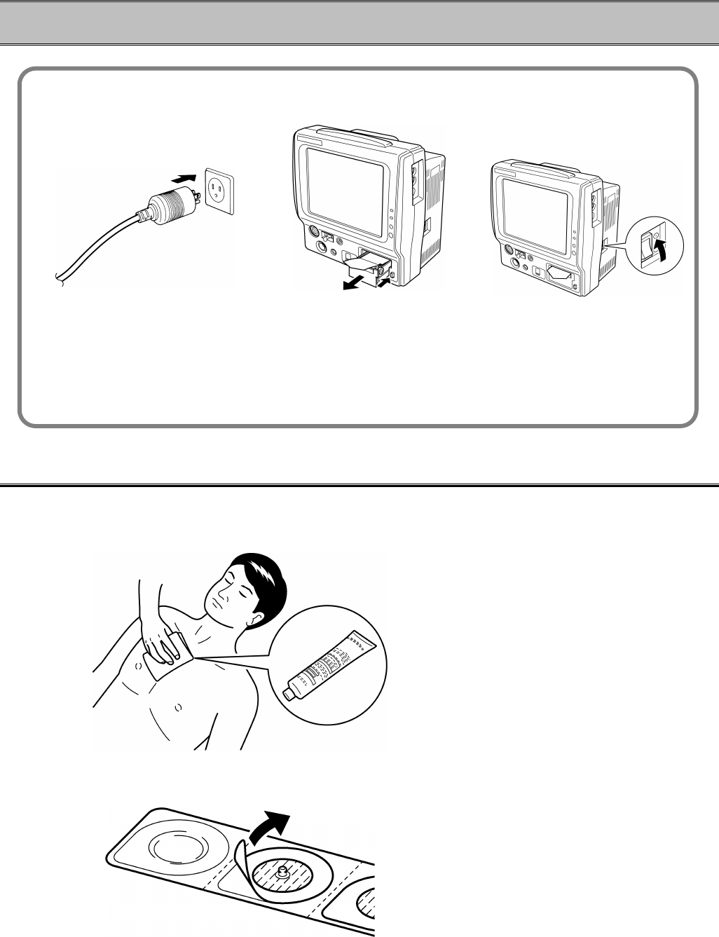
1. Check the grounding. 2. Check the recording paper. 3. Turn ON the power.
The magazine will be released by pressing the
magazine release button.
Properly ground using the
3-way AC plug.
The grounding is required to
prevent AC noise.
Open the recorder magazine, and
check that there is enough
amount of paper installed.
Turn ON the power and
check for appropriate
display.
Before Attaching the Electrodes
1. Clean the electrode sites with an alcohol swab or other skin preparation. If necessary,
shave the electrode sites to remove excessive hair.
2. Peel off the backing of disposable electrode.
Pay attention not to touch the electrode jelly.
3−3
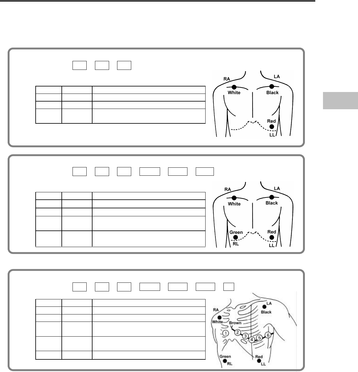
Electrode Placement
There are 3-electrode, 4-electrode, 5-electrode application depending on the cable type.
Using the 4-electrode or 5-electrode application allows simultaneous monitoring of 2 ECG
waveforms, and high accuracy of arrhythmia analysis can be attained.
Also, the displayed lead type can be changed.
For 3-electrode lead (1 waveform monitoring)
Lead Type Ⅰ / Ⅱ / Ⅲ
Symbol Color Electrode Site
RAWhite On the right infraclavicular fossa
LABlack On the left infraclavicular fossa
LL Red On the left midclavicular line, near the
supracrestal line.
For 4-electrode lead (Simultaneous 2 waveforms monitoring)
Lead Type Ⅰ / Ⅱ / Ⅲ / aVR / aVL / aVF
Symbol Color Electrode Site
RAWhite On the right infraclavicular fossa
LABlack On the left infraclavicular fossa
LL Red On the left midclavicular line, near the
supracrestal line.
RL Green On the right midclavicular line at the
same height as F.
For 5-electrode lead (Simultaneous 2 waveforms monitoring)
Lead Type Ⅰ / Ⅱ / Ⅲ / aVR / aVL / aVF / V
Symbol Color Electrode Site
RAWhite On the right infraclavicular fossa
LABlack On the left infraclavicular fossa
LL Red On the left midclavicular line, near the
supracrestal line.
RL Green On the right midclavicular line at the
same height as F.
VBrown Chest Lead (V1∼V6)
3
To Acquire ECG Waveform
3−4
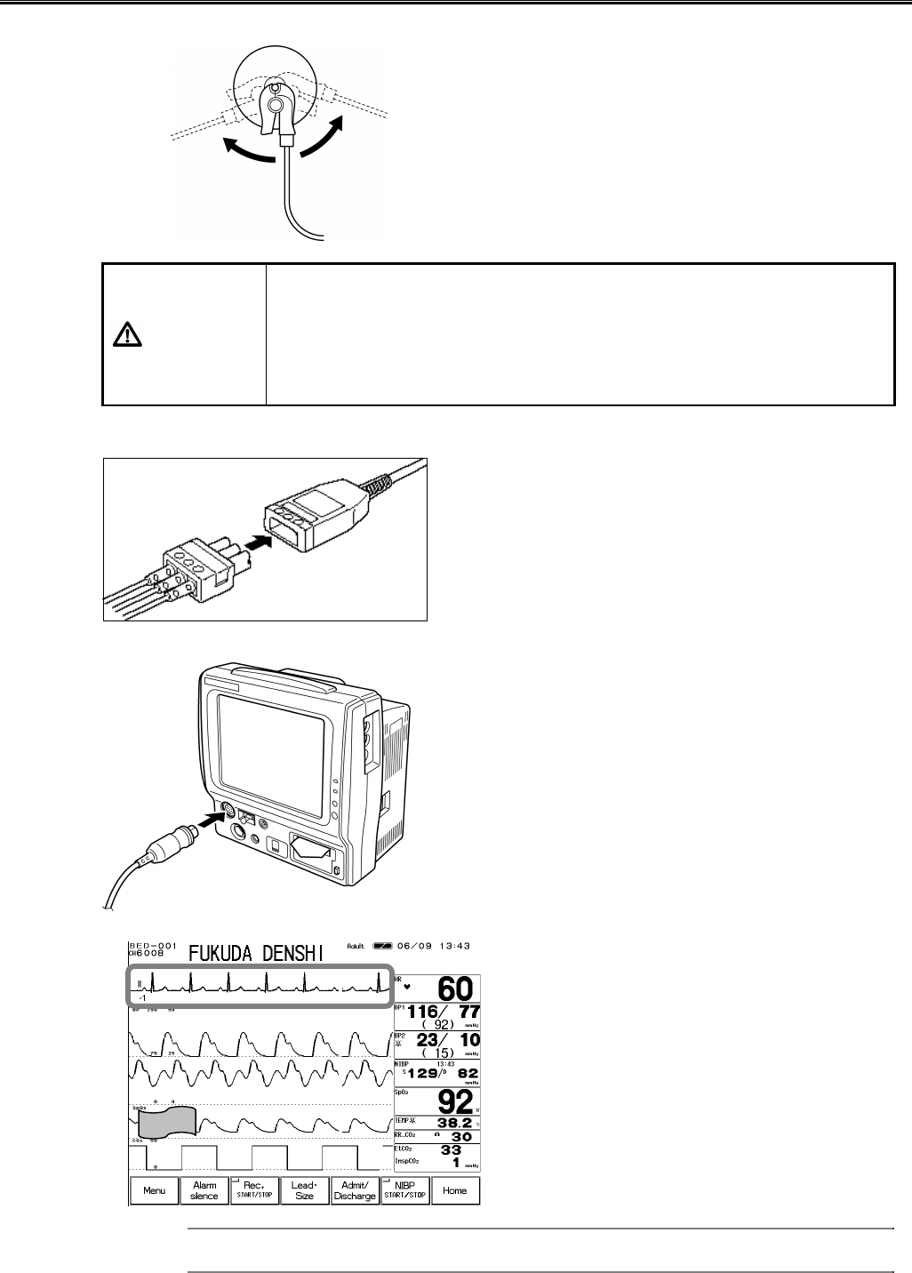
Connection to the Patient Monitor
1. Connect the lead cable to the electrode.
Clip on the lead cable end to the electrode convex
part.
CAUTION
?
The indication for continuous use of the electrode is about one day.
?
Replace the electrode if the skin contact gets loosen due to perspiring,
etc.
?
When an electrode is attached at the same location for a long time,
some patients may develop a skin irritation. Check the patient’s skin
condition periodically and change the electrode site as required.
2. Connect the lead cable to the relay cable.
3. Plug in the relay cable to the ECG input connector (green) of the patient monitor.
4. Verify that the ECG waveform is displayed on the monitor.
Adjust the waveform size and position. The
monitoring lead can be also changed.
Reference
Refer to “ 6. Parameter Setup ECG” for size / lead setup.
3−5
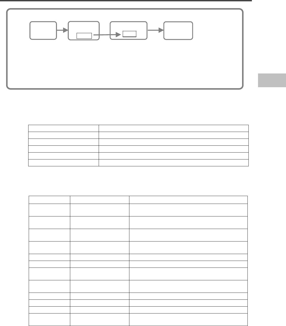
About the Arrhythmia Analysis
Arrhythmia Analysis Flow
Learn
Waveform
QRS
Judgement
VPC?
Pattern Matching
VPC!
Arrhythmia
The arrhythmia detection algorithm learns the normal waveform of the patient and
compares the waveform (QRS pattern) and RR interval for each heartbeat to determine the
VPC. It compares the parameters such as QRS amplitude, QRS width, QRS polarity, RR
interval, and selects abnormal QRS. Then the QRS with suspected VPC is pattern
matched to distinguish the noise and VPC. This will finally determine the VPC and
generate the arrhythmia alarm.
●QRS Classification
Each heartbeat will be classified to the following patterns according to the QRS judgement.
N (Normal) Normal QRS beat
V (VPC) Ventricular Extrasystole
S (SVPC) Supraventricular Extrasystole
P (Pacing Beat) Pacing beat
F (Fusion Beat) Fusion beat of pacing and spontaneous beat
? (Undetermined Beat) Learning arrhythmia, or beat not matching the pattern
●Arrhythmia Type
With the above QRS judgement, the following 12 types of arrhythmia alarm can be generated.
Type Meaning Detection Criteria
ASYSTOLE Cardiac Arrest Cardiac arrest is detected for more than
preprogrammed time.
VF Ventricular Fibrillation A random, rapid electrical activity of the heart is
detected.
VT Ventricular Tachycardia 9 or more continuous ventricular beats are detected.
(HR: 140bpm / 120bpm or over)
SLOW_VT 9 or more continuous ventricular beats are detected.
(HR: under 140bpm / 120bpm)
TACHY Tachycardia HR is over the upper alarm limit.
BRADY Bradycardia HR is below the lower alarm limit.
RUN Consecutive VPC Continuous VPC exceeding the preprogrammed
value is detected.
COUPLET Couplet Ventricular
Extrasystole 2 continuous beats of VPC is detected.
PAUSE Cardiac arrest of 1.5 seconds and over is detected.
BIGEMINY Ventricular Bigeminy QRS pattern of V-N-V-N-V-N is detected.
TRIGEMINY Ventricular Trigeminy QRS pattern of V-N-N-V-N-N is detected.
FREQUENT Frequent VPC VPC exceeding the preprogrammed value is
detected within 1 minute.
3
To Acquire ECG Waveform
3−6
Filter Selection
●Filter Mode Setup
The waveform frequency characteristic can be selected from Monitor Mode, ESIS Mode, or ST
Display Mode according to the monitoring purpose.
1. Monitor Mode Frequency Characteristic Adult / Pediatric:0.5∼40Hz Neonate:1.6∼40Hz
This is the standard mode for ECG monitoring. The upper frequency is set to 40Hz to reduce
artifact caused by EMG, etc.
2. ESIS Mode Frequency Characteristic Adult / Pediatric:1.6∼15Hz Neonate:1.6∼15Hz
By selecting this mode when using electrosurgical instrument, electrical noise can be largely
reduced. Do not select this mode unless using electrosurgical instrument.
3. ST Display Mode Frequency Characteristic Adult / Pediatric:0.05∼40Hz
Select this mode if ST measurement is the main purpose of ECG monitoring.
NOTE If “Neonate” is selected as patient type, ST display mode can not be selected
NOTE
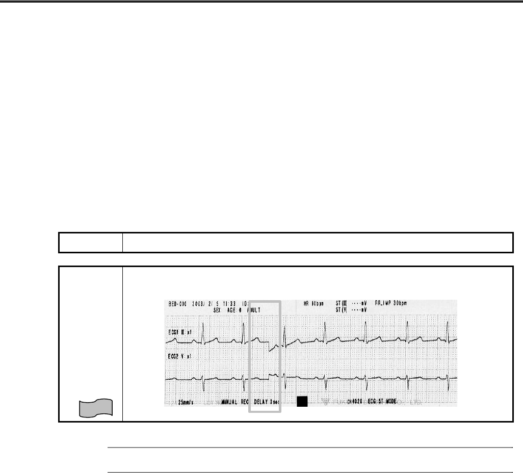
When the filter setup is changed, a notch will appear on the ECG waveform due
to the change in frequency characteristic.
Reference
Refer to ” 6. Parameter Setup ECG” for details of filter mode.
3−7
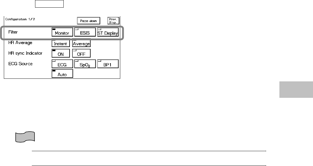
●Procedure for Filter Mode Selection
1. Press the ECG parameter key and display the ECG setup menu.
2. Press the Config. key.
3. Select the filter mode from 3 selections.
●AC Filter
If the ECG waveform is interfered with AC noise, the AC filter cuts off the frequency component
(50Hz or 60Hz).
The AC filter is always set to ON.
Reference
Refer to “8. System Configuration Hospital Setup AC Filter” for AC filter setup (50Hz or 60Hz).
Lead Cable Types
There are various combinations of lead cable connecting type and electrode material.
Contact our service representative for details and select the appropriate electrode.
【for 3-electrode】ECG Relay Cable (defibrillation-proof) CI-700D-3
ECG Relay Cable (electrosurgery-proof) CI-700E-3
ECG Lead Cable 3380.0648.13
【for 4-electrode】ECG Relay Cable (defibrillation-proof) CI-700D-4
ECG Relay Cable (electrosurgery-proof) CI-700E-4
【for 5-electrode】ECG Relay Cable (defibrillation-proof) CI-700D-5
ECG Relay Cable (electrosurgery-proof) CI-700E-5
ECG Lead Cable 3380.0661.13
3
To Acquire ECG Waveform
3−8
− Respiration (Impedance Measurement) −
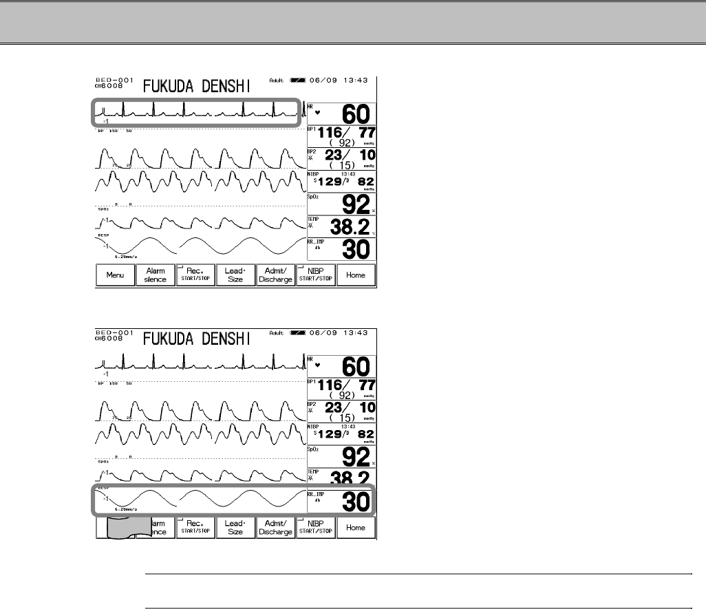
1. Verify that the ECG waveform is properly acquired.
The respiration waveform is detected from lead
Ⅱof ECG mentioned in the previous section.
Therefore if stable ECG is acquired, the
respiration waveform can be acquired at the
same time.
2. Verify that the respiration waveform and respiration rate is displayed on the home display.
Adjust the waveform size, baseline position and
sweep speed.
Reference
Refer to “6. Parameter Setup Respiration” for scale / baseline setup.
Refer to ”8. System Configuration Sweep Speed” for sweep speed setup.
3−9
− To Measure the SpO2 −
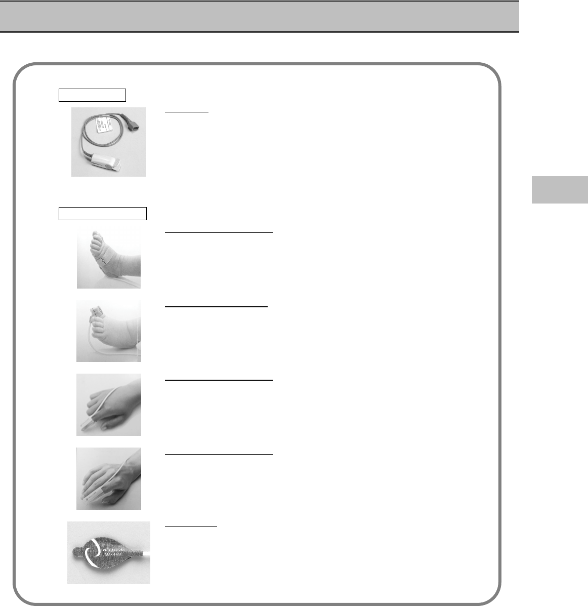
1. Prepare an appropriate probe or sensor for the patient.
Sensor Types
Probe Type (Reusable type, for adult finger)
DS-100A
For adult with weight of 40kg and over.
This is for temporary use. When continuously using for long period
of time, use the following single-use type.
Single Use Type
OXISENSORⅢ N-25 (for neonate toe)
For neonate with weight of 3kg and over.
OXISENSORⅢ I-20 (for pediatric toe)
For pediatric with weight of 3kg∼20kg
OXISENSORⅢ D-20 (for pediatric finger)
For pediatric or adult with weight of 10kg∼50kg
OXISENSORⅢ D-25 (for adult finger)
For adult with weight of 30kg and over.
MAX Fast (for adult forehead)
For adult with weight of 40kg and over.
With the use of new technology of NELLCOR®, OXIMAX, stable
monitoring during body motion / low perfusion is possible.
3
To Measure the SpO2
3−10
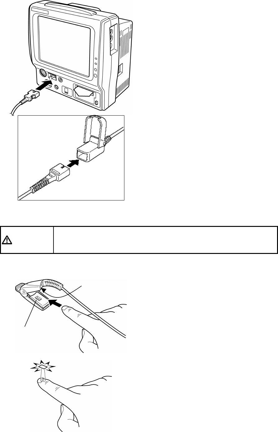
2. Connect the sensor to the patient monitor.
(1) Connect the SpO2 relay cable (DOC-10) to
the SpO2 connector on the patient monitor.
(2) Insert the sensor into the SpO2 relay cable
connector, and lock with the transparent
part.
3. Attach the sensor to the patient.
CAUTION If the nail is rough, dirty, or manicured, accurate measurement will not be
possible. Change the finger or clean the nail before attaching the probe
and sensor.
【Probe Type Sensor】
(1) Attach the probe as shown on left.
The probe cable should be on the nail side.
(2) Adjust the sensor so that the light-emitting
part (on cable side) touches the root of the
nail, and close the probe.
Light Reception Part
Light Emitting Part
3−11
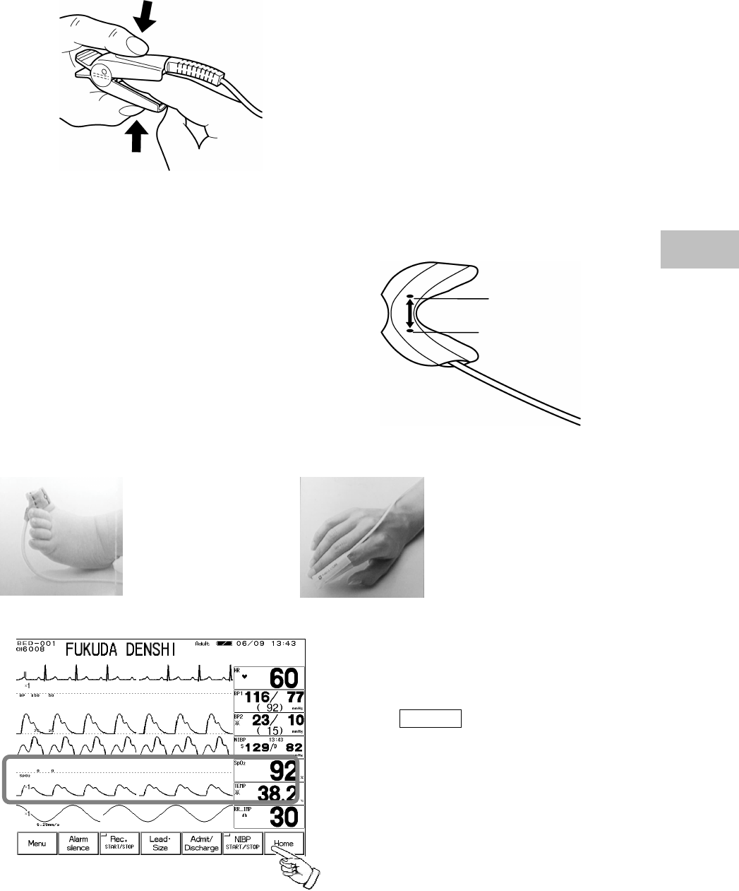
(3) Press the probe lightly so that the finger and
the rubber cover are appressed.
This is to stabilize the probe, and to avoid
ambient light.
【Single-use Type】
(1)Clean the attachment site with alcohol, etc.
(2)Align the light emitting element and light
receiving element of the sensor with the
measuring site in between when attaching the
sensor to patient.
(3)Fixate the cable with surgical tape so that the sensor does not come off when a cable is pulled.
Attachment to the toe Attachment to the finger
4. Verify that the SpO2 is displayed.
Press the HOME key on the lower part of
the display.
Verify that the SpO2 measurement and SpO2
waveform are displayed on the home display.
Light Receiving Element
Light Emitting Element
3
To Measure the SpO2
3−12
●Functional and Fractional Saturation
The DS-7100 measures functional SpO2 and may therefore produce measurements that differ
from devices measuring fractional SpO2. "Functional" SpO2 is the amount of oxygenated
hemoglobin expressed as a percentage of the total amount of hemoglobin capable of transporting
oxygen. By utilizing the light of two different wavelengths, the DS-7100 can analyze for both
oxygenated and deoxygenated hemoglobin, and consequently, can determine the functional SpO2.
The DS-7100 does not detect the presence of abnormal hemoglobin, such as carboxyhemoglobin
or methemoglobin.
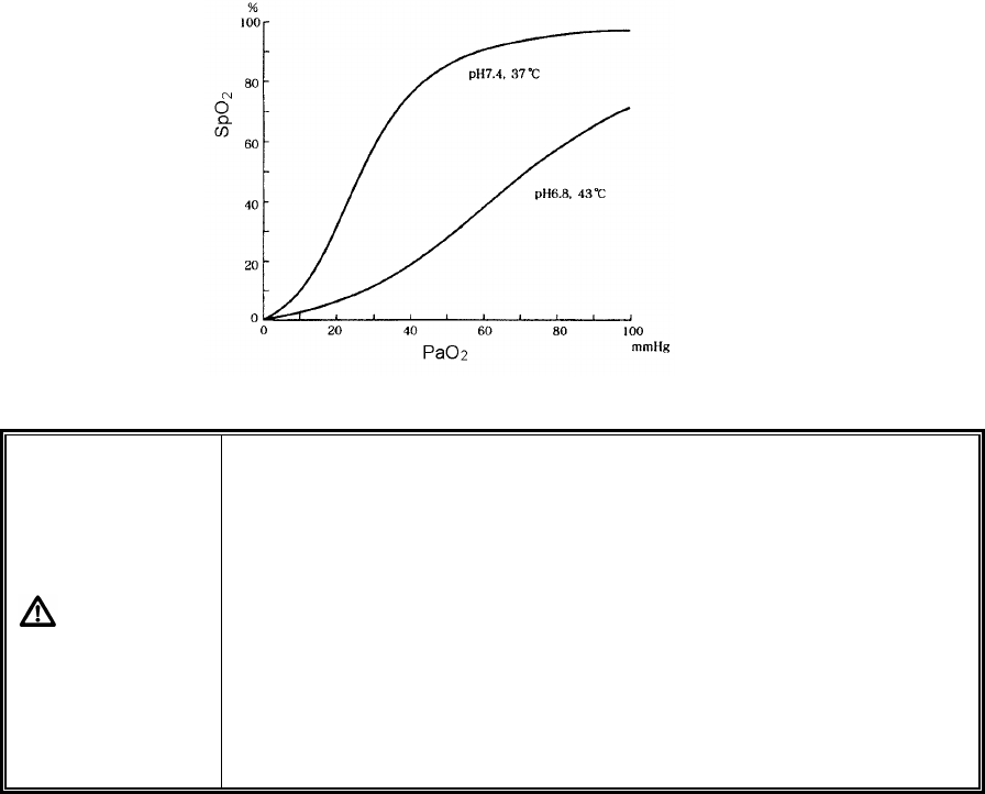
●Measured Versus Calculated Saturation
When SpO2 is calculated from a blood gas measurement of the partial pressure of arterial oxygen
(PaO2), the calculated value may differ from the DS-7100 SpO2 measurement. This is because
the calculated SpO2 may not have been corrected for the effects of variables that shift the
relationship between PaO2 and SpO2 : temperature, pH, the partial pressure of carbon
dioxide(PaCO2), and the concentrations of 2, 3-DPG and fetal hemoglobin.
WARNING
?
When measuring the SpO2 of patient with high fever or peripheral
circulatory insufficiency, check the sensor attachment periodically and
change the attachment site. The temperature of attachment site will
rise 2∼3?C due to the sensor heat which may result in burn injury.
?
For the following case, accurate measurement may not be possible.
?
Patient with excessive abnormal hemoglobin (HbCO, MetHb)
?
Patient with the pigment injected to the blood
?
Patient receiving CPR treatment
?
When a sensor is applied to a limb with NIBP cuff, arterial catheter, or
intracatheter
?
When measuring at site with venous pulse
?
Patient with body motion
?
Patient with small pulse

3−13
CAUTION
?
If irritation such as skin reddening or skin fit appears with the sensor
use, change the attachment site or stop using the sensor.
?
When fixating the sensor with a tape, do not wind the tape too strong.
At the same time, check the blood flow constantly so that congestion
is not generated at the peripheral.
?
Even a short duration of attachment may inhibit the blood flow and
generate compression necrosis and burn injury.
?
Change the sensor attachment site constantly (every 4 hours). As
the temperature of sensor attachment site normally rises 2∼3?C,
compression necrosis and burn injury may generate.
?
As the skin of neonate / low birth weight infant is immature, change
the sensor attachment site more frequently depending on the
condition.
?
Direct sunlight to the sensor area can cause a measurement error.
Place a black or dark cloth over the sensor.
?
When not performing the measurement, unplug the relay cable and
sensor from the SpO2 connector. Otherwise, the measurement data
may be erroneously displayed by the ambient light.
3
To Measure the SpO2