Fukuda Denshi Co DS7100 Patient Monitor User Manual DS71v1 1 FA 001 Preface 001
Fukuda Denshi Co Ltd Patient Monitor DS71v1 1 FA 001 Preface 001
Contents
User manual 1

i
Preface
Thank you for purchasing this product.
Before using this product, read the following precautions to make sure the product is
used correctly and safely.
Safety Precautions ・・・・・・・・・・・・・・・・・・・・・・・・・・・・・・・・・ii
Labels Attached to the Unit ・・・・・・・・・・・・・・・・・・・・・・・ii
Measurement Unit for Each Parameter ・・・・・・・・・・・・ iv
Graphic Symbols ・・・・・・・・・・・・・・・・・・・・・・・・・・・・・・・・v
Precautions for Safe Operation of Medical Electrical
Equipment ・・・・・・・・・・・・・・・・・・・・・・・・・・・・・・・・・・・・ vi
Precautions for Safe Operation of Medical Telemetry
(DS-7141, DS-7101LT)・・・・・・・・・・・・・・・・・・・・・・・・・・vii
Precautions about the Maintenance・・・・・・・・・・・・・・ viii
Precautions about the Pacemaker ・・・・・・・・・・・・・・・・ ix
Non-Explosion Proof・・・・・・・・・・・・・・・・・・・・・・・・・・・・ ix
Defibrillation Safety・・・・・・・・・・・・・・・・・・・・・・・・・・・・・ ix
Electrosurgery Safety ・・・・・・・・・・・・・・・・・・・・・・・・・・・・x
Precautions about Magnetic Resonance Imaging ・・・・x
Precautions about Connections to Peripheral Devices xi
Precautions about the Fuse・・・・・・・・・・・・・・・・・・・・・・ xi
Accessories and Optional Accessories ・・・・・・・・・・・・ xi
Precautions about the DS-7100 System ・・・・・・・・・・・xii
Precautions for Use of SpO2 Sensor ・・・・・・・・・・・・ xviii
Precautions for Use of NIBP Cuff ・・・・・・・・・・・・・・・ xviii
Disposing of Equipment, Accessories, or Components
・・・・・・・・・・・・・・・・・・・・・・・・・・・・・・・・・・・・・・・・・・・・ xviii
Precautions about Transportation・・・・・・・・・・・・・・・ xviii
Precautions about RTC or Data Backup ・・・・・・・・・ xviii
Precautions for Use of Lithium-Ion Battery Pack ・・・ xix
To Prepare for Emergency Use・・・・・・・・・・・・・・・・・・・xx
Electromagnetic Compatibility ・・・・・・・・・・・・・・・・・・・・・・ xxi
Precautions for Safe Operation under Electromagnetic
Influence ・・・・・・・・・・・・・・・・・・・・・・・・・・・・・・・・・・・・・ xxi
EMC Guidance ・・・・・・・・・・・・・・・・・・・・・・・・・・・・・・・ xxi
●Compliance to the Electromagnetic Emissions xxii
●Compliance to the Electromagnetic Immunity (1)
・・・・・・・・・・・・・・・・・・・・・・・・・・・・・・・・・・・・・・・・・・xxii
●Compliance to the Electromagnetic Immunity (2)
・・・・・・・・・・・・・・・・・・・・・・・・・・・・・・・・・・・・・・・・・ xxiii
●Recommended Separation Distances between
Portable and Mobile RF Communications Equipment
and the DS-7100 System・・・・・・・・・・・・・・・・・・・ xxiv
ii
Safety Precautions
?
Read the “Safety Precautions” thoroughly before use to ensure correct and safe use of the product.
?
Be sure to follow the precautions indicated below, as these are important messages related to safety.
DANGER Failure to follow this message may cause immediate threat of death or serious
injury, or complete failure of the equipment.
WARNING Failure to follow this message may result in death or serious injury, or
complete failure of the equipment.
CAUTION Failure to follow this message may cause injury or failure to the equipment.
NOTE A note is not related to product safety, but provides information about the
correct use and operating procedures to prevent incorrect operation and
malfunction of the equipment.
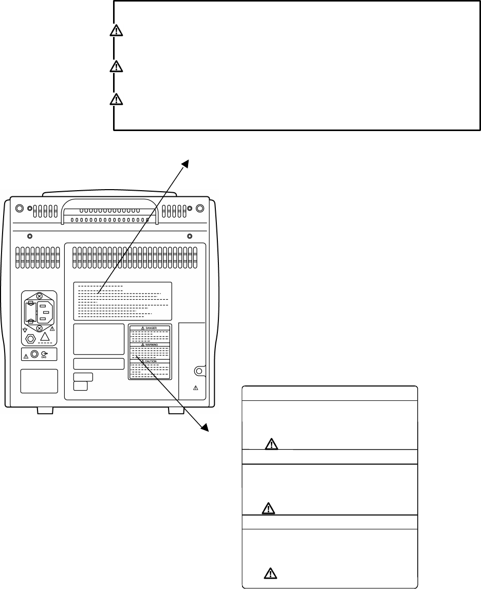
Labels Attached to the Unit
Make sure to read the warning labels attached to the unit and comply with these requirements while
operating the unit.
CAUTION
Do not damage or erase the warning labels attached to the unit.
These warning labels contain descriptions important for handling and
operating the unit properly and safely. A damaged label may compromise
safe operation.
iii
DS-7100 System
DANGER
Risk of explosion if used in the presence of flammable anesthetics.
CAUTION
Before connecting, read instruction manual.
CAUTION
To reduce the risk of electric shock, do not remove the cover.
Refer servicing to qualified service personnel.
DANGER
? Use only the batteries specified for this
device.
? Do not disassemble or modify the battery.
The battery incorporates protection circuitry
for safety purposes.
WARNING
? Installation of the battery should be
performed only by our service
representative, to avoid any risk of electric
shock to the operator or malfunction of the
device.
CAUTION
? The life cycle of the battery is 1 year.
? The battery charges when the power cord is
connected to a hospital-grade outlet.
? It takes approximately 2.5 hours to fully
charge an empty battery.

iv
Measurement Unit for Each Parameter
The measurement units for this equipment are as follows.
Detail Parameter Display Unit Default
ECG HR bpm
(beats per minute)
Invasive Blood
Pressure PR_BP bpm
(beats per minute)
Heart Rate/Pulse
Rate *1
SpO2PR_SpO2
bpm
(beats per minute)
ST Level ECG ST mm, mv mv
VPC ECG VPC beats / hour
Impedance
Respiration RR_IMP Bpm
(breaths per minute)
Respiration Rate
*2 CO2RR_CO2
Bpm
(breaths per minute)
Impedance
Respiration APNEA s (second)
Apnea
CO2APNEA s (second)
Invasive Blood
Pressure Invasive Blood
Pressure BP mmHg, kpa mmHg
Non-Invasive Blood
Pressure Non-Invasive Blood
Pressure NIBP mmHg, kPa mmHg
Arterial Oxygen
Saturation SpO2SpO2%
Temperature Temperature TEMP ?C / ?F?C
End-Tidal CO2
Concentration CO2EtCO2mmHg, kPa, % mmHg
Inspiratory CO2
Concentration CO2InspCO2mmHg, kPa, % mmHg
*1 HR/PR will be displayed in the color selected for ECG/HR.
*2 RR will be displayed in the color selected for RESP.
v
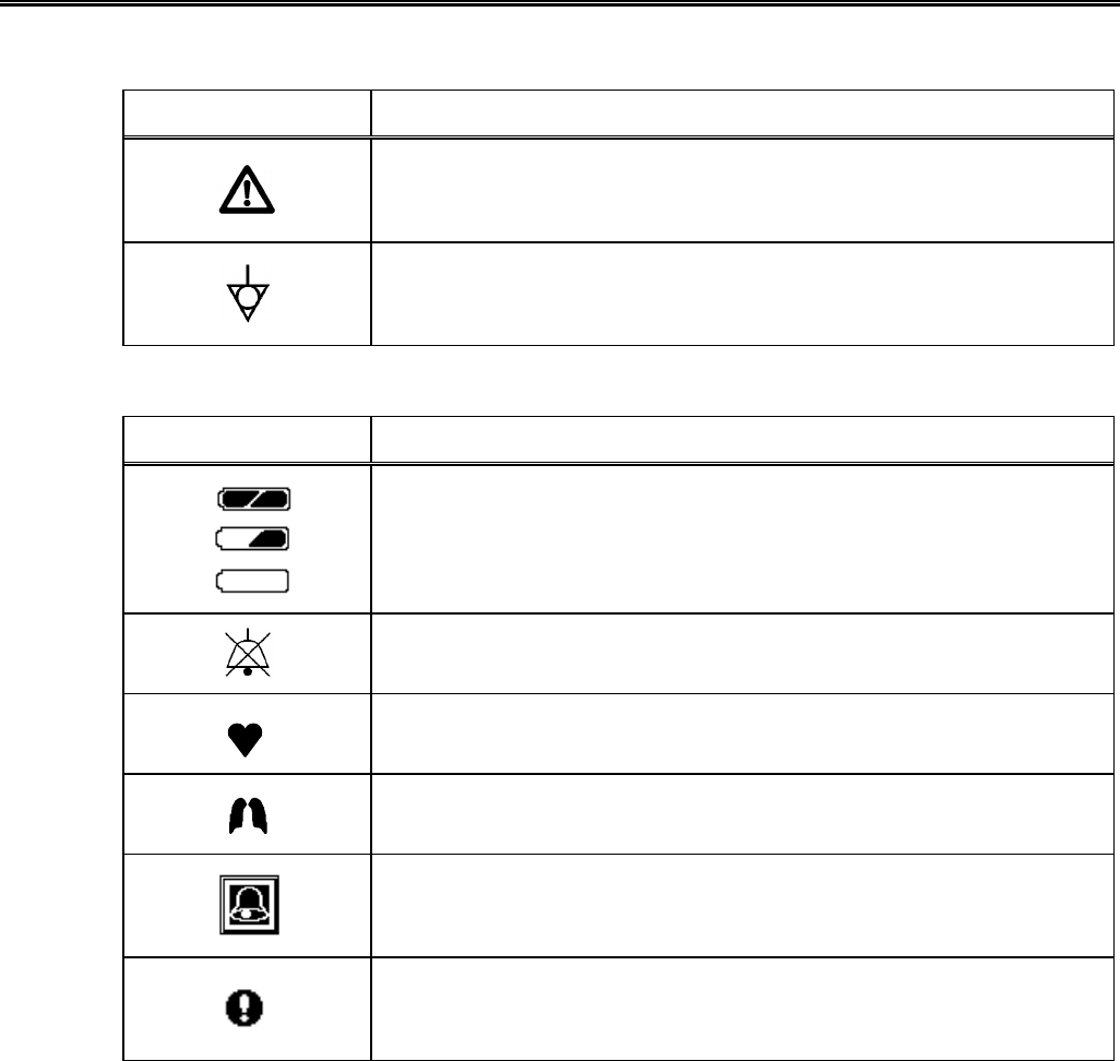
Graphic Symbols
The following symbols are used for this equipment.
DS-7100 System: Main Unit
Symbol Description
Caution; refer to accompanying documents
Indicates the need to refer to related accompanying documents before
operation.
Equipotential Terminal
Indicates the terminal to equalize the potential difference when
interconnecting the devices.
DS-7100 System: Symbols displayed on the screen
Symbol Description
Battery Mark
Indicates battery capacity and remaining volume during battery operation.
Alarm OFF
Indicates the alarm is OFF.
Heart Rate Synchronization Mark
This mark flashes synchronizing to the heartbeat.
Respiration Synchronization Mark
This mark flashes synchronizing to the inspiration.
Event Key Mark
Displayed when an alarm generates. ON/OFF of the display can be
selected on the ward setup.
Message Mark
Displayed in the parameter key when an alarm message is present for
that parameter.

vi
Precautions for Safe Operation of Medical Electrical Equipment
CAUTION
Read the following precautions thoroughly to correctly operate the device.
?
Users should have a thorough knowledge of the operation before using this
system.
?
Pay attention to the following when installing and storing the equipment.
?
Do not install or store in an area where the equipment will be subject to
splashing water.
?
Do not install or store in an area where the environmental conditions,
such as atmospheric pressure, temperature, humidity, ventilation,
sunlight, dust, sodium, sulfur, will adversely affect the system.
?
Place the equipment on a stable surface where there is no inclination,
vibration, or shock (including during transportation).
?
Do not install or store in an area where there are chemical or gasses
stored.
?
Verify the power frequency, voltage and allowable current (or power
consumption).
?
Ensure the grounding is proper by connecting the accompanying power
cable to the hospital grade outlet.
?
Before operating the system, verify the following items
?
Verify the power voltage.
?
Check the cable connection and polarity to ensure proper operation of
the equipment.
?
Make sure the power system has adequate earth ground.
?
Ensure that all cables are firmly and safely connected.
?
Pay special attention when the device is used in conjunction with other
equipment as it may cause erroneous judgement and danger.
?
Ensure all patient connections are proper and secure.
?
During operation of the system, verify the following items.
?
Always observe the system and patient to ensure safe operation of the
equipment.
?
If any abnormality is found on the equipment or patient, take appropriate
measures such as ceasing operation of the equipment in the safest way
for the patient.
?
Do not allow the patient to come in contact with the device.
?
After using the system, verify the following items.
?
Unplug all the cables from the patient before turning off the power.
?
When unplugging the cables, do not apply excessive force by pulling on
the cord. Pull by the connector part of the cable.
?
Clean the accessories and cables, and keep them together in one place.
?
Keep the unit clean to ensure proper operation of the next use.
?
If the equipment is damaged and in need of repair, user should not attempt
service. Label the unit “OUT OF ORDER” and contact Fukuda Denshi.
?
Do not remodel the equipment.
?
Maintenance Check
?
Make sure to periodically check the equipment, accessories and cables.
?
Before reusing the device that has been left unused for a while, make
sure that the device works normally and safely.
?
When using the electrosurgical knives or defibrillator with this equipment,
verify proper attachment of patient ground plate, ECG electrode type for the
electrosurgical knives, and paste volume, output energy for the defibrillator.
Also, verify that proper ground is selected.

vii
Precautions for Safe Operation of Medical Telemetry (DS-7141, DS-7101LT)
CAUTION
Precautions for Safe Operation of Medical Telemetry
To operate the device correctly, read the following precautions carefully.
?
The medical institution (hereinafter referred as “Institution”) must decide the
telemetry installation plan for the medical institution in order to prevent
interference and interference between transmitters (telemetry based on
destination country’s radio law).
?
When using telemetry which requires zone location, the institution is to set
up the zones as an operation unit for each transmitter to prevent electronic
interference between telemetry throughout the medical institution.
?
When using telemetry which requires zone location, display and identify
each prepared zone in the equipment.
?
When laying receiver antenna for each transmitter, the institution has to be
examined so as not to generate electronic interference.
?
Based on the above examination result, the institution places each receiver
antenna as required.
In managing, be sure to follow the precautions below.
?
The institution appoints a person to manage the wireless channels for the
whole medical institution. And when using telemetry which requires zone
location, the institution nominates a person to manage the wireless
channels in each zone (a “Zone Manager”). However, when using such
telemetry in a local medical institution, one person can perform both
functions.
?
Select a telemetry manager who understands the characteristics and
functionality of telemetry systems, and is skilled in operating telemetry.
?
When installing telemetry, the Overall Manager and the Zone Manager
have to understand the precautions for use of the telemetry in advance.
?
The Overall Manager takes responsibility of wireless channel management
and transmitter storage for the whole medical institution by giving proper
instruction.
?
The Overall Manager creates a management log, list of wireless channels,
management status for the whole medical institution (hereinafter referred to
as the “management log”). When changing a wireless channel, register it
in the log and give proper instructions to the zone manager or to the user.
?
The Zone Manager assumes responsibility for managing the wireless
channels, storing, and managing telemetry.
?
The Zone Manager assigns the transmitter to the user, and provides
enough education for use inside the zone.
?
The telemetry user verifies operation of the transmitter/receiver before use.
?
The telemetry user, if using the telemetry in a zone location, follows the
instructions of the zone manager for the zone and gives instructions to the
patient if required.
?
When interference or breakdown occurs in telemetry communication, the
user is required to inform the zone manager and the overall manager of the
problems. The zone manager and overall manager are to deal with the
problem properly and/or contact their nearest Fukuda Denshi
representative for service.
viii
Precautions about the Maintenance
Safety Inspection and Maintenance
For safe operation of the equipment, regular inspection and maintenance is required. Once a year,
check all cables, devices, and accessories for damage, earth impedance, earth and enclosure leakage
currents, and all alarm functions. Also, ensure that all safety labels are legible. Maintain a record of
these safety inspections.
Immediate maintenance has to be carried out if ;
?
the equipment was subjected to extreme mechanical stress, e.g. after a heavy fall.
?
the equipment was subjected to liquid spill.
?
the monitoring function is interrupted or disturbed.
?
parts of the equipment enclosure are cracked, removed, or lost.
?
any connector or cable shows signs of deterioration.
Reference
Refer to “10. Maintenance” for details.
WARNING Never open the housing while the equipment is in operation or connected to
hospital grade outlet as it may result in electric shock.
Maintenance, Modifications, and Repairs
Fukuda Denshi is liable for the safety, reliability, and performance of its equipment only if;
?
Maintenance, modifications, and repairs are carried out by authorized personnel.
?
Components are used in accordance with Fukuda Denshi operating instructions.
A full technical description of the DS-7100 system is available from your local Fukuda Denshi
representative.
ix
Precautions about the Pacemaker
WARNING
Minute ventilation rate-adaptive implantable pacemakers can occasionally
interact with certain cardiac monitoring and diagnostic equipment, causing
the pacemakers to pace at their maximum programmed rate. The cardiac
monitoring and diagnostic equipment may possibly send wrong information.
If such event occurs, please disconnect the cardiac monitoring and
diagnostic equipment, or follow the procedures described in the operation
manual of the pacemaker.
(For more details, contact FUKUDA DENSHI personnel, your institution’s
professionals, or your pacemaker distributors.)
Reference
“Minute Ventilation Rate-Adaptive Pacemakers”
FDA alerts health professionals that minute ventilation rate-
adaptive implantable pacemakers can occasionally interact with
certain cardiac monitoring and diagnostic equipment, causing
pacemakers to pace at their maximum programmed rate.
[October 14, 1998 (Letter: www .fda.gov/cdrh/safety.html) – FDA]
Non-Explosion Proof
DANGER
Never operate the equipment in the presence of flammable anesthetics, high
concentration of oxygen, or inside hyperbaric chamber. Also, do not
operate the equipment in an environment in which there is a risk of
explosion.
Explosion or fire may result.
Defibrillation Safety
WARNING
?
When defibrillating, keep away from the electrodes or medicament
applied to the patient chest. If this is not possible, remove the electrodes
or medicament before defibrillating.
If the defibrillator paddles directly contact the electrodes or medicament,
electrical shock may result by the discharged energy.
?
When defibrillating, make sure that the electrodes, sensor cables, or relay
cables are firmly connected to the device.
Contacting the metal part of the disconnected cable may result in
electrical shock by the discharged energy.
?
When defibrillating, do not touch the patient and the metal part of the
device or cables. Electric shock may result by the discharged energy.
x
Electrosurgery Safety
WARNING
The monitoring system contains protection against interference generated by
electrosurgical instruments. However, operating conditions, surgery site with
respect to the location of ECG electrodes, or the type of instrument used, may
cause noise on the ECG. The noise is generated at the tip of an electrical
knife and is difficult to completely eliminate because of the frequency
components of the ECG. To reduce electrosurgical interference, take the
following precautions:
Location
Locate the electrosurgical unit as far as possible from this unit and the
patient cable. This will help reduce interference on the ECG through the
monitor or cables.
Power Supply
Connect the electrosurgical unit to a power supply that is different from that
of the monitor. This will help prevent interference through the power
cable.
Electrode Placement
The amount of interference is considerably different depending on the
electrode position and surgery site. Place the ECG electrodes as far
away as possible from the surgery site and the ground plate. Do not
place electrodes in the path between the surgery site and the ground plate.
If the electrodes are placed in this path, the amount of interference will be
quite large. Position (+) and (–) electrodes as close as possible to each
other.
Ground Plate
When using electrosurgical instruments, make sure the contact between
the patient and the ground plate is secure. If the connection is
incomplete, the patient may suffer a burn at the electrode site.
Precautions about Magnetic Resonance Imaging
WARNING
?
Do not operate this equipment in magnetic resonance imaging (MRI)
environments.
?
When conducting MRI test, remove the electrodes and sensors connected
to the patient (test subject).
The local heating caused by the induced electromotive force may cause
burn injury to the patient (subject). For details, refer to the operation
manual for the MRI testing device.
xi
Precautions about Connections to Peripheral Devices
In the interest of safe and sufficient performance of this equipment, the connection of other
manufacturers’ equipment to the monitor is not authorized, unless the connection is explicitly approved
by Fukuda Denshi. It is the user’s responsibility to contact Fukuda Denshi to determine the
compatibility and warranty status of any connection made to another manufacturer’s equipment.
WARNING
For the connector with mark, only the peripheral devices specified by
Fukuda Denshi should be connected with the given procedure. Use of an
unspecified device may cause electric shock to the patient and/or operator due
to excessive leakage current.
CAUTION
All the peripheral device connectors on the DS-7100 system are isolated from
the power supply, but the peripheral devices are not isolated. To prevent
danger of electric shock, always position the peripheral devices away from the
patient.
When connecting peripheral devices to DS-7100 system, it is the user’s responsibility to verify that the
overall system complies with IEC 60601-1-1, “Collateral Standard: Safety Requirements for Medical
Electrical Systems”.
Precautions about the Fuse
DANGER If the fuse burns out, contact Fukuda Denshi Service Representative. Do not
continue using it as internal damage to the equipment may be considered.
Accessories and Optional Accessories
WARNING Use only the cables specified by Fukuda Denshi.
Use of other cables may result in increase in emission or decrease in
immunity.
xii
Precautions about the DS-7100 System
DANGER
?
When connecting to other device, contact Fukuda Denshi service
representative.
Danger such as electric shock may result to the patient and operator.
?
When monitoring a patient with wireless telemetry, make sure the patient
data is properly received at the central monitor. Pay special attention
when channel ID at the bedside monitor is changed.
WARNING
?
Do not connect unit or cable not authorized by Fukuda Denshi to any I/O
connector. If done so by mistake, the DS-7100 system can not deliver its
maximum performance and the connected units may be damaged,
resulting in a safety hazard.
?
Use only the accompanying 3-way AC power cable. Use of other cables
may result in electric shock to the patient and the operator.
?
The power cable must be connected to AC 115V outlet.
?
When using multiple ME equipment simultaneously, perform equipotential
grounding to prevent potential difference between the equipment. Even a
small potential difference may result in electric shock to the patient and the
operator.
?
The patient type selection influences the precision of the QRS detection
and NIBP measurement. Make sure the correct selection is made.
?
The pacemaker use selection influences the precision of the QRS
detection and arrhythmia analysis. Make sure the correct selection is
made.
?
When measuring the SpO2 of patient with high fever or peripheral
circulatory insufficiency, check the sensor attachment periodically and
change the attachment site. The temperature of attachment site will rise 2
∼3?C due to the sensor heat which may result in burn injury.
?
For the following case, accurate measurement may not be possible.
?
Patient with excessive abnormal hemoglobin (HbCO, MetHb)
?
Patient with the pigment injected to the blood
?
Patient receiving CPR treatment
?
When measuring at site with venous pulse
?
Patient with body motion
?
Patient with small pulse
?
Before the measurement, make sure the patient type ( Adult / Child /
Neonate ) is properly selected. Otherwise, correct measurement can
not be performed, and congestion or other injury may result.
?
Pay attention when measuring the NIBP of patient with bleeding disorders
or hypercoagulation. The cuff inflation may cause petechia or circulatory
failure by the blood clot.
?
Use the specified sampling tube and nasal prong manufactured by Oridion.
?
Always consider the circumference of the intubation tube when using the
airway adapter. If inappropriate airway adapter is used for a patient with
low ventilation, CO2 may mix in to the inspired air resulting in incorrect
measurement, or apnea detection may become difficult.
?
When measuring CO2 concentration of a patient treated with mouth-to-
mouth resuscitation, Jackson-Rees circuit, Mapleson D circuit of which CO2
gas may mix in, the value may be displayed lower than the actual value.
?
When the system alarm is suspended, all the alarm will be suspended even
if the parameter alarm is set to ON. Also, the alarm event will not be
stored as recall.
?
If the upper/lower alarm limit of the parameter is set to OFF, or arrhythmia
alarm is set to OFF, alarm will not function even if the system alarm is set to
ON. Pay attention when setting them OFF.
?
If the QRS pace mask function is turned OFF, a decrease in heart rate may
not generate HR or ASYSTOLE alarms due to erroneously detected QRS.
Turn this function OFF only if you are sure that pacing failure will not occur,
or when the patient can be constantly monitored.

xiii
WARNING
?
Objective and constant arrhythmia detection is possible through the fixed
algorithm incorporated in this monitor.
However, excessive waveform morphology change, motion artifact, or the
inability to determine the waveform pattern may cause an error, or fail to
make adequate detection. Therefore, physicians should make final
decisions using manual recording, alarm recording and recall waveform for
evaluation.
?
When setting the monitor on a trolley, use 2 fixing screws to ensure safety.
Otherwise, the monitor may fall off the trolley, resulting in injury or damage
to the monitor.
?
Use the trolley only with the equipment specified by Fukuda Denshi.
Otherwise, the monitor and trolley may fall down, resulting in injury or
damage to the monitor.
?
Be sure to lock both casters when using or storing the trolley.
The trolley may move or fall down, resulting in injury or damage to the
monitor.
?
Do not use or store the trolley where it will be subject to inclination of 10
degrees or more. The trolley or defibrillator may fall resulting in injury or
damage to the monitor.
?
Some wireless combinations of telemetry transmitters may generate
interference with other devices.
?
Before selecting the channel, verify it will not interfere with other channels.
?
Make sure the telemetry manager of your system is aware of any changes
to the telemetry channels.
?
If transmitters are used in a neighboring medical facility, your facility and
neighboring facility must make agreements on the setting of telemetry
channels to prevent telemetry interference.
?
The purpose of this respiration alarm is to alert the user to evaluate for the
possible occurrence of apnea events by identifying the absence of
respiration. It is not intended to be classified as an “Apnea Monitor” and will
not identify the condition creating the possible event. (Central, Obstructive
or Mixed.)
CAUTION
?
Systems
?
The monitor should be kept apart at least 20cm from the head of patient
or operator.
?
Use only the accessories specified for this device. Otherwise, proper
function cannot be executed.
?
For quality improvement, specifications are subject to change without
prior notice.
?
The battery deteriorates with the repeated use, which shortens the
usable time.
?
The arrhythmia detection level corresponds with the displayed waveform
size. Select an appropriate size for monitoring.
?
The display panel utilizes exclusive fluorescent light for the backlight.
Since this fluorescent light deteriorates by the life cycle, the display may
become dark, scintillate, or may not light by the long term use. In such
case, contact your nearest service representative.
?
Always operate the touch screen with fingers or touch screen pen. Do
not touch with a pen-point or other hard-edged instruments.
Malfunction of the touch screen or damage may result.
?
ECG Monitoring
?
The indication for continuous use of the electrode is about one day.
?
Replace the electrode if the skin contact gets loosen due to perspiring,
etc.
?
When an electrode is attached at the same location for a long time, some
patients may develop a skin irritation. Check the patient’s skin condition
periodically and change the electrode site as required.

xiv
CAUTION
?
The threshold level for arrhythmia detection changes with ECG
waveform size. Set a proper waveform size for monitoring.
When the waveform size is ?1/4, ?1/2, or ?1, the detection threshold is
250 µV.
When the waveform size is ?2 or ?4, the detection threshold is 150 µV.
?
Automatic size/position of the ECG is effective only at the time the
AUTO key is pressed. This does not continually adjust size and
position.
?
There are some cases when pacemaker pulse can not be detected
depending on the pacemaker type, pulse voltage, pulse width, electrode
lead type (unipolar, bipolar), or electrode placement which causes the
pacemaker pulse amplitude to decrease and disables pacemaker pulse
detection.
?
If signals similar to a pacemaker pulse are present, such as electric
blanket noise or excessive AC frequency noise, these may be
erroneously detected and displayed as a pacemaker pulse.
?
When automatic QRS and pacemaker pulse overlap (ex. fusion beat,
etc.), QRS detection cannot be performed properly. In this case, the
heart rate is degraded.
?
When continuously detecting AC noise artifact as pacemaker pulses,
QRS detection stops and heart rate is extremely degraded. Also
arrhythmia cannot be detected.
?
Respiration Monitoring
?
When the following relay cables are used, respiration can not be
measured.
・Relay Cable CI‐700E_3 (Electrosurgery-proof, 3-electrode)
・Relay Cable CI‐700E_4 (Electrosurgery-proof, 4-electrode)
・Relay Cable CI‐700E_5 (Electrosurgery-proof, 5-electrode)
?
When a defibrillator is used during respiration monitoring, a large offset
voltage will be placed on the ECG electrodes, which may cause
interruption of monitoring for a few seconds.
?
When the following lead cables are used, respiration cannot be
measured.
・Lead Cable #3380.0648.16 (Electrosurgery-proof, 3-electrode)
・Lead Cable #3380.0661.16 (Electrosurgery-proof, 5-electrode)
?
SpO2 Monitoring
?
If the nail is rough, dirty, or manicured, accurate measurement will not be
possible. Change the finger or clean the nail before attaching the probe
and sensor.
?
If irritation such as skin reddening or skin fit appears with the sensor use,
change the attachment site or stop using the sensor.
?
When fixing the sensor with a tape, do not wind the tape too tight. At
the same time, check the blood flow constantly so that congestion is not
generated at the peripheral.
?
Even a short duration of attachment may inhibit the blood flow and
generate compression necrosis and burn injury
?
Change the sensor attachment site constantly (every 4 hours). As the
temperature of sensor attachment site normally rises 2∼3?C,
compression necrosis and burn injury may generate.
?
As skin for neonate / low birth weight infant is immature, change the
sensor attachment site more frequently depending on the condition.
?
Direct sunlight to the sensor area can cause a measurement error.
Place a black or dark cloth over the sensor.
?
When not performing the measurement, unplug the relay cable and
sensor from the SpO2 connector. Otherwise, the measurement data
may be erroneously displayed by the ambient light.
?
NIBP Monitoring
?
If the air hose is twisted, or weighed down, the cuff air can not be
exhausted. Properly arrange the cuff and air hose.

xv
CAUTION
?
For the following situation, measurements will be terminated.
When the measurement time has exceeded 120 seconds for adult, 90
seconds for child, 60 seconds for neonate.
When the inflation value has exceeded 300mmHg for adult, 200mmHg
for child, 150mmHg for neonate.
?
If used with the incorrect patient type, it will not only cause erroneous
measurement, but the inflating level for the adult may be applied to child
or neonate causing dangerous situation to the patient.
?
The 1-minute interval measurement will always start from 00 second.
Pressing the 1min start key will start the measurement from the next
00 second.
?
The 1-minute interval measurement will automatically stop after 10
minutes or 20 minutes and returns to the previous interval mode setup.
The selection of 10min / 20min can be made on the NIBP
configuration menu.
?
The alarm function will be ineffective for the BP value measured by Quick
SYS regardless of the ON/OFF selection of NIBP alarm.
?
BP Monitoring
?
If the SYS value is abnormally high, or DIA is abnormally low, a
resonance may be the cause. If the resonance can not be eliminated by
adjusting the blood pressure filter, check the BP line and use a thick,
short, and hard catheter.
?
When the main power is turned ON, the BP value will not be displayed
until zero balance is performed. Make sure to perform the zero
balance.
?
Each time the blood pressure transducer or tubing is replaced, the zero
balance procedure is required to ensure accurate measurements.
?
The zero balance procedure is required for the following case.
?
When starting the measurement.
?
When the position of the heart has changed due to body movement.
?
When the position of the transducer has changed.
?
When measuring for a long period of time and there is a possibility of
measurement error due to change in ambient temperature, etc.
?
When the connector is connected / disconnected, or transducer is
replaced.
?
If the mean BP display is set to OFF, the mean BP alarm will not be
generated. Also, the mean BP will not be displayed on the tabular
trend. Be cautious when setting the mean BP display OFF.
?
CO2 Monitoring
?
Perform calibration after 20 minutes when the main power of the
DS-7100 system is turned ON.
?
Do not disconnect the sampling tube during calibration.
If disconnected, calibration will cease.
?
Conduct CO2 calibration for the following case.
?
When 6 months has elapsed from the last calibration date.
?
When EtCO2 measurement is not stable or accuracy is degraded
compared with other measuring device.
?
When the patient monitor was not used for a while, or when EtCO2
was not measured for a while.
?
CO2 monitoring will cease when the ventilation connector is covered.
?
Use only the specified sampling tube for CO2 monitoring.
?
Alarm
?
A faint sound will be generated when setting a minimum volume for the
alarm sound, but be cautious not to miss any alarm. Adjust the volume
to a recognizable level.
?
Alarm messages will be displayed according to the priority. (Level 1 →
Level 2 → Level 3 → Level 4)
?
For the same alarm level, the alarm message for the newer alarm will be
displayed.
?
The alarm message for the arrhythmia alarm will continue to be
displayed for 30 seconds after the alarm is resolved.

xvi
CAUTION
?
While the “LEAD OFF” message is displayed, HR alarm and arrhythmia
alarm will not function. Leaving this condition unresolved may result in
missing a sudden change of the patient. Promptly check the electrodes
when this message is displayed.
?
If the alarm with the higher priority occurs during alarm recording, the
recording in process will be ceased and starts the alarm recording with
the higher priority.
?
Whether to use the SEC alarm function and its threshold selection should
be based on the patient’s clinical indication portent and medical
evaluation.
?
If the SpO2 alarm and SEC alarm setup is set to OFF, the SEC alarm
integral value will be set to 0.
?
System Configuration
?
When performing telemetry transmission, the numeric data
corresponding to the waveform should be selected for display.
Otherwise, the displayed waveform or numeric data may not be
transmitted.
?
If the time/date is not correctly set, or changed during monitoring,
erroneous condition may occur to NIBP measurement, periodic
recording, trend and NIBP list data.
?
If the time/date is changed during monitoring, patient’s age will not be
recalculated.
?
When connected to a wired network, the same time/date with the central
monitor will be set.
?
The alarm ON/OFF setup will remain effective even when the power is
turned OFF. Be cautious not to miss any important alarm by leaving the
alarm silenced.
?
When performing telemetry transmission, the numeric data
corresponding to the waveform should be selected for display.
Otherwise, the displayed waveform or numeric data may not be
transmitted.
?
The setup of channel ID and group ID should be performed only by our
service representative. Users should not perform this procedure as
malfunction to the equipment may occur.
?
The Bed ID is factory set to 000. If connected to the wired network with
the ID unchanged, monitoring on the central monitor will not be possible.
?
When connecting to the wired network, verify that the Bed ID does not
duplicate with other bedside monitors. Otherwise, monitoring on the
central monitor for both bedside monitors will not be possible.
?
To connect to the wired network, set the Bed ID in the range from 001 to
048.
?
There are following restrictions when connecting the DS-7100 system to
the DS-LANⅡnetwork.
?
The DS-7100 system is not corresponded to the AU-5500N 8-
channel recorder. The data for the DS-7100 system can not be
recorded on the AU-5500N.
?
When the measurement unit of BP is kPa, BP waveform, BP numeric
data, NIBP numeric data, NIBP list will not be transmitted. These
will be treated as not measured data, and will not be displayed on the
central monitor. Also, alarm limit setup on the central monitor can
not be performed.
?
When the temperature unit is ?F, the temperature data will not be
transmitted. It will be treated as not measured data, and will not be
displayed on the central monitor. Also, alarm limit setup on the
central monitor can not be performed.
?
Arrhythmia alarm of TACHY, BRADY, SLOW_VT, COUPLET,
PAUSE will not be transmitted.
?
For numeric data displayed as “×××”, maximum or minimum value
of measurable range will be transmitted.
?
The numeric data displayed as “−−−” will be treated as not
measured data.
?
For QRS classification, the “S” printed on the built-in recorder will be
printed as “N” on the HR-500 Recorder.

xvii
CAUTION
?
When DS-5800N/NX/NXMB is used as a central monitor, recall,
graphic trend, tabular trend, and ST measurement function will not
be displayed.
?
When DS-5700 is used as a central monitor, ST measurement function
will not be displayed
?
A delay will occur for the communication with the central monitor. The
delay is about 1.5 seconds for the waveform, about 1.5~4.0 seconds for
the numeric data, and about 1.5~2.0 seconds for the alarm.
?
When waveform and numeric data display is set to OFF, the alarm
generation and tabular/graphic trend will be also set to OFF.
?
Patient Admit / Discharge
?
If you start monitoring a new patient without performing a discharge
procedure for the previous patient, new data will be added to the
previous data which will result in inaccuracy.
?
The setup for the alarm mode and display mode remains stored even
when the power is turned off or when discharging procedure is
performed. Before monitoring, make sure the current monitoring mode
is suitable for the patient’s condition.
?
Resuming monitoring will resume the alarm in suspension.
?
Arrhythmia Analysis
?
For proper arrhythmia detection and ECG monitoring, verify proper
electrode placement, lead selection, and ECG waveform size. If
necessary, turn ON the AC filter. Improper electrode placement, lead
selection, and ECG waveform size can cause errors in detection.
?
IC Card
?
Use only the specified IC card.
?
Restart the system after reading the setup data from the IC card.
The setup data will become effective after the system is restarted.
?
Maintenance
?
Always operate the touch screen with fingers or touch screen pen. Do
not touch with a pen-point or other hard-edged instruments.
Malfunction of the touch screen or damage may result.
?
Do not clean the touch panel using strong acid
?
A special coating is applied to the surface of the touch panel. Wipe the
surface with the soft cleaning cloth provided as optional accessory or
with commercially available eyeglass cleaning cloth.
?
Clean the equipment frequently so stains can be removed easily.
?
To prevent injury, it is recommended to wear gloves when cleaning the
equipment.
?
Do not allow liquids such as alcohol or cleaning solution enter the
monitor or connectors.
?
Do not use organic solvents, thinner, toluene and benzene to avoid
damaging the resin case.
?
Do not polish the housing with abrasive or chemical cleaner.
?
When sterilizing the entire room using a spray solution, pay close
attention not to have liquids get into the monitor or connectors.
?
Use only neutral detergent to clean the housing. Do not use chemical
cloth, scrub brush, abrasive, polishing powder, hot water, volatile solvent
and chemicals (cleanser, thinner, toluene, benzine, benzol, and synthetic
detergent for house and furniture), or sharp-edged tools. The surface
resin coating may be damaged, resulting in discoloration, scratches, and
other problems.
?
Do not open the housing.
?
Replace the components periodically as specified.

xviii
Precautions for Use of SpO2 Sensor
DANGER
Burn Risk in Using SpO2 Sensor
In SpO2 monitoring, always use the sensor/relay cable specified by Fukuda
Denshi. If any other sensor/relay cable is used, a high temperature rise of
the sensor may place the patient in danger of burns.
If there are any questions regarding the sensor/relay cable use for SpO2
measurements of this device, please contact Fukuda Denshi service
representative.
Precautions for Use of NIBP Cuff
CAUTION This product contains natural rubber latex which may cause allergic reactions.
Disposing of Equipment, Accessories, or Components
CAUTION When disposing of the equipment, accessories, or components, use an
industrial waste distributor. Do not dispose of as ordinary waste.
Precautions about Transportation
For transporting the DS-7100 system, pack with specified packing materials.
Reference
Refer to “11. Technical Information Specification / Performance” for environmental condition
during transportation.
Precautions about RTC or Data Backup
CAUTION
?
The DS-7100 system is equipped with a built-in clock. When the power of
the DS-7100 system is turned off, this clock is backed up by a lithium primary
battery.
If incorrect time is displayed when turning on the power, a low battery may be
the cause. In such case, contact Fukuda Denshi service representative for
replacing the battery.
?
To protect the data during voltage dip, short interruptions and voltage
variations on power supply input lines or during short duration of power
turned OFF, this monitor performs 5-minute (approx.) data backup using the
secondary battery. The data may not be protected if the power is turned off
within 30 minutes from power on.
xix
Precautions for Use of Lithium-Ion Battery Pack
DANGER
?
This battery pack is intended for exclusive use with the DS-7100 system (or
other specified equipment). Do not use with other equipment. If charged
on unspecified equipment, the performance and life cycle of the battery
pack deteriorates or abnormal current flows causing damage, leakage,
heating, fuming, explosion, ignition of the battery.
?
Do not disassemble or remodel the equipment. If the security apparatus
or protector inside the battery gets damaged, it may cause heating, fuming,
explosion, ignition of the battery.
?
Do not use the battery if leaked or transformed. If the security apparatus
inside the battery is damaged, it may cause heating, fuming, explosion,
ignition of the battery.
?
When installing the battery to the monitor, verify the polarity direction is
correct. If not, it may cause leakage, heating, fuming, explosion, ignition.
?
If the leaked solution of the battery gets into the eyes, do not rub the eyes.
Wash thoroughly with clean water and immediately receive medical
treatment from the doctor. If not treated soon, it may cause serious injury.
WARNING
?
If the leaked solution of the battery gets on to the skin or clothes,
immediately wash down with rinse water. If not treated soon, it may cause
serious injury.
?
If charging does not complete within the specified charging time, remove
the battery and disconnect the power supply cable from the outlet.
Otherwise, it may result in leakage or heating of the battery.
?
Do not throw into fire or heat the battery. The insulator may melt, gas
exhaust vent or security apparatus may get damaged, or electrolyte may
ignite causing heating, fuming, explosion, ignition of the battery.
?
Do not connect the (+) and (--) terminals of the battery with a wire or any
other metal. Also, do not carry or store the battery with any metal such as
necklace, hairpins, etc. The battery may short causing excessive current
flow which may result in heating, fuming, explosion, ignition of the battery or
heating of the metal (wire, necklace, hairpin, etc.)
?
Do not solder the battery directly. The heat may melt the insulator or
damage the security apparatus which may result in heating, fuming,
explosion, ignition of the battery.
?
Do not put the battery in microwave oven or a pressure cooker.
If heated suddenly or if sealed condition breaks, it may result in leakage,
heating, fuming, explosion, ignition of the battery.
?
Do not drive a nail in, hit with a hammer, or step on the battery. The
battery may explode and transform causing a short out which may result in
heating, fuming, explosion, ignition of the battery.
?
Do not apply strong impact or throw the battery. This may result in
leakage, heating, fuming, breakage, ignition of the battery. Also, if the
security apparatus incorporated in the battery gets damaged, the battery
charges with abnormal current and voltage which results in leakage,
heating, fuming, explosion, or ignition.
?
Do not get the battery wet with water, sea water or chemicals. If the
security apparatus incorporated in the battery gets damaged, it may result
in heating, fuming, explosion, ignition of the battery.
?
Do not connect the battery directly to power outlet or cigarette heater
socket in a car. A high voltage application will cause excessive current
flow and abnormal chemical reaction inside the battery causing abnormal
current flow during discharging. This may result in heating, fuming,
explosion, ignition of the battery.
?
Do not use or leave the battery in a high temperature (80 ?C or over) such
as near the fire or heater. If the resin separator gets damaged by heat,
the battery shorts causing heating, fuming, explosion, ignition.
?
If the battery is leaking or generating an abnormal odor, immediately
remove the battery away from the fire. The leaked electrolyte may cause
heating, fuming, explosion, ignition.
xx
CAUTION
?
Do not peel off or scratch the exterior tubing.
?
Do not use or leave the battery in high temperature. It may result in
leakage or deterioration of the performance / life cycle of the battery.
?
Immediately stop using the battery if any abnormality is found during use.
?
Do not use / store the battery in reach of infants.
?
If the monitor is expected not to be used for a long time, turn off the power
and unplug the power cable from the outlet. Otherwise it may result in
battery leakage.
NOTE Users should not attempt to install or replace the battery pack.
For installation and replacement of the battery pack, contact our service
representative.
To Prepare for Emergency Use
1.Battery Pack
(1) The battery self-discharges even when not in use. If there is any possibility to use the
battery in emergency, the power cable should be always connected to the power receptacle.
To fully charge the empty battery, it takes approximately 2.5 hours when the monitor is not
operating, and approximately 13 hours when the monitor is operating.
Reference
Refer to “2. Basic Operation To Use with the Battery Pack”
(2) The performance of the battery deteriorates with the repeated use. To maintain the initial
performance, replace the battery at least once a year. It is recommended to indicate the
start usage date on the battery so that replacing date can be easily recognized.
2. Accessories / Optional Accessories
(1) The ECG electrodes are consumables. Always prepare extra supplies of electrodes.
(2) Check if any wire break on the patient cables once a week.
xxi
Electromagnetic Compatibility
The performance of this device under electromagnetic environment complies with IEC60601-1-2
(1993).
Precautions for Safe Operation under Electromagnetic Influence
CAUTION
If any sorts of electromagnetic wave, magnetic field, or static electricity exist
around the device, noise interference or malfunction of the device may occur.
If any unintended malfunction or noise occurs during monitoring, check the
magnetic influence and take appropriate countermeasures.
The following are examples of the common cause and countermeasures.
?
Cellular Phone
The radio wave may cause malfunction to the device.
Cellular phones and radio sets should be turned off in the room (building)
where medical device is located.
?
Static Electricity
In a dry environment (room), static electricity is likely to occur. Take the
following countermeasures.
?
Both operator and patient should remove any static electricity before
entering the room.
?
Humidify the room.
?
Lightning
?
A lightning nearby may induce excessive voltage to the equipment. If any
danger is suspected, use the uninterruptible power supply system.
?
High frequency noise interference from other device through the power outlet
?
Check where the noise is originated and remove it using filtering device,
etc.
?
Stop using the device that is originating the noise.
?
Use other power outlet.
EMC Guidance
This equipment complies with IEC60601-1-2 (1993). However, if portable transmitter or wireless LAN
equipment is used extremely nearby, the electromagnetic influence may largely exceed the compliance
level and may cause unexpected phenomenon such as noise interference on the waveform, etc.
Therefore, this equipment should be used in a location specified by each medical institution.
If any unexpected noise interference on the waveform or failure to the peripheral device occurs, stop
using the equipment and follow the instruction of the technician.
The following is the information relating to EMC (Electromagnetic Compatibility).
(When using this equipment, verify that it is used within the environment specified below.)

xxii
●Compliance to the Electromagnetic Emissions
The DS-7100 system is intended for use in the electromagnetic environment specified below.
Emissions Test Compliance Electromagnetic Environment - Guidance
RF Emissions
CISPR 11 Group 1
The equipment uses RF energy that is necessary for the internal
functioning of the equipment itself. Therefore, its RF emissions
are very low and are not likely to cause any interference in nearby
electronic equipment.
RF Emissions
CISPR 11 Class A
This equipment is suitable for use in all establishments other than
domestic and those directly connected to a low-voltage power
supply network which supplies buildings used for domestic
purposes.
●Compliance to the Electromagnetic Immunity (1)
The DS-7100 system is intended for use in the electromagnetic environment specified below. It
should be assured that the DS-7100 system is used in such an environment.
Immunity Test IEC60601-1-2
Test Level Compliance Level Electromagnetic Environment -
Guidance
Electrostatic
Discharge (ESD)
IEC61000-4-2
?3kV contact
?8kV air
?3kV contact
?8kV air
Floors should be wood, concrete
or ceramic tile. If floors are
covered with synthetic material,
the relative humidity should be at
least 30%.
Electrical fast
transient / burst
IEC61000-4-4
?1kV for power supply
lines
?0.5kV for input/output
lines
?1kV for power supply
lines
?0.5kV input/output
lines
Power supply quality should be at
levels characteristic of a typical
location in a typical commercial or
hospital environment.
Surge
IEC61000-4-5
?2kV:
line to ground
?1kV:
line to line
?2kV:
line to ground
?1kV:
line to line
Power supply quality should be at
levels characteristic of a typical
location in a typical commercial or
hospital environment.
xxiii
●Compliance to the Electromagnetic Immunity (2)
The DS-7100 system is intended for use in the electromagnetic environment specified below. It
should be assured that the DS-7100 system is used in such an environment.
Immunity Test IEC60601-1-2
Test Level Compliance Level Electromagnetic Environment -
Guidance
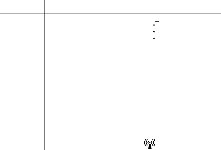
Radiated RF
IEC61000-4-3 3V/m
26MHz ∼ 1.0GHz 3V/m Recommended Separation Distance
d = 1.2 P
d = 1.2 P 80MHz∼800MHz
d = 2.3 P 800MHz∼2.5GHz
Where P is the maximum output
power rating of the transmitter in watts
(W) according to the transmitter
manufacturer and d is the
recommended separation distance in
meters (m).
Field strengths from fixed RF
transmitters, as determined by an
electromagnetic site survey, should be
less than the compliance level in each
frequency range.
Interference may occur in the vicinity
of equipment marked with the
following symbol:
Note 1 :At 80Mhz and 800MHz, the higher frequency range applies.
Note 2 :These guidelines may not apply in all situations. Electromagnetic propagation is affected by
absorption and reflection from structures, objects and people.
aField strengths from fixed transmitters, such as base stations for radio (cellular/cordless) telephones
and land mobile radios, amateur radio, AM and FM radio broadcast and TV broadcast can not be
predicted theoretically with accuracy. To assess the electromagnetic environment due to fixed RF
transmitters, an electromagnetic site survey should be considered. If the measured field strength
in the location in which this monitor should be observed to verify normal operation. If abnormal
performance is observed, additional measures may be necessary, such as reorienting or relocating
this monitor.
bOver the frequency range 150MHz to 80MHz, field strength should be less than 3V/m.

xxiv
●Recommended Separation Distances between Portable and Mobile RF
Communications Equipment and the DS-7100 System
The DS-7100 system is intended for use in an environment in which radiated RF disturbances are
controlled. The electromagnetic interference can be prevented by maintaining a minimum distance
between portable and mobile RF communications equipment (transmitters) and the DS-7100 system as
recommended below, according to the maximum output power of the communications equipment.
Separation Distance according to Frequency of Transmitter (m)Rated Maximum
Output Power of
Transmitter
(W)
26MHz ∼ 80MHz
d = 1.2 P
80MHz ∼ 800MHz
d = 1.2 P
800MHz ∼ 1GHz
d = 2.3 P
0.01 0.12 0.12 0.23
0.1 0.38 0.38 0.73
11.2 1.2 2.3
10 3.8 3.8 7.3
100 12 12 23
For transmitters rated at a maximum output power not listed above, the recommended separation
distance d in meters (m) can be determined using the equation applicable to the frequency of the
transmitter, where P is the maximum output power rating of the transmitter in watts (W) according to the
transmitter manufacturer.
Note 1 :At 80MHz and 800MHz, the separation distance for the higher frequency range applies.
Note 2 :These guidelines may not apply in all situations. Electromagnetic propagation is affected by
absorption and reflection from structures, objects and people.
xxv
WARNING
FCC Radiation Exposure Statement:
This equipment with a built-in telemeter complies with FCC
radiation exposure limits set forth for an uncontrolled
environment. This equipment should be installed and
operated with minimum distance 20cm between the radiator
and your body (excluding extremities: hands, wrists, and feet)
and must not be co-located or operated with any other antenna
or transmitter.
WARNING
Operation of this equipment requires the prior coordination with
a frequency coordinator designated by the FCC for the
Wireless Medical Telemetry Service.
CAUTION
FEDERAL LAW RESTRICTS THIS DEVICE TO SALE
BY OR ON THE ORDER OF A PHYSICIAN.
xxvi
Blank Page

xxvii
Contents
Preface
1. General Description Describes the outline of this equipment.
1
2. Basic Operation Describes the basic operation for monitoring.
2
3. Vital Application Describes the procedure for vital application, etc.
3
4. Monitoring Setup Describes the procedures to set the monitor
according to the monitoring purpose.
4
5. Admit / Discharge of a Patient Describes the procedure to admit or discharge a
patient.
5
6. Parameter Setup Describes the procedure to set the measurement
condition, size, scale, etc. for each parameter.
6
7. Function Describes about the functions such as arrhythmia
analysis, trend, recall, etc.
7
8. System Configuration Describes about the system configuration such as
night mode, alarm mode, display mode, etc.
8
9. Installation Describes about the environment for use,
wireless system, etc.
9
10. Maintenance Describes about the maintenance,
troubleshooting of this equipment.
10
11. Technical Information Lists the specification, default settings, pin
assignments of external connector, etc.
11
12. Accessories Lists the accessories and optional accessories for
this equipment.
12

xxviii
Preface
Safety Precautions・・・・・・・・・・・・・・・・・・・・・・・・・・・・・・・・・・ii
Labels Attached to the Unit ・・・・・・・・・・・・・・・・・・・・・・・ii
Measurement Unit for Each Parameter ・・・・・・・・・・・・ iv
Graphic Symbols ・・・・・・・・・・・・・・・・・・・・・・・・・・・・・・・ v
Precautions for Safe Operation of Medical Electrical
Equipment・・・・・・・・・・・・・・・・・・・・・・・・・・・・・・・・・・・・・ vi
Precautions for Safe Operation of Medical Telemetry
(DS-7141, DS-7101) ・・・・・・・・・・・・・・・・・・・・・・・・・・・・vii
Precautions about the Maintenance ・・・・・・・・・・・・・・ viii
Precautions about the Pacemaker ・・・・・・・・・・・・・・・・ ix
Non-Explosion Proof ・・・・・・・・・・・・・・・・・・・・・・・・・・・・ ix
Defibrillation Safety ・・・・・・・・・・・・・・・・・・・・・・・・・・・・・ ix
Electrosurgery Safety ・・・・・・・・・・・・・・・・・・・・・・・・・・・ x
Precautions about Magnetic Resonance Imaging・・・・ x
Precautions about Connections to Peripheral Devices xi
Precautions about the Fuse ・・・・・・・・・・・・・・・・・・・・・・ xi
Accessories and Optional Accessories・・・・・・・・・・・・・ xi
Precautions about the DS-7100 System ・・・・・・・・・・・xii
Precautions for Use of SpO2 Sensor・・・・・・・・・・・・・ xviii
Precautions for Use of NIBP Cuff ・・・・・・・・・・・・・・・ xviii
Disposing of Equipment, Accessories, or Components
・・・・・・・・・・・・・・・・・・・・・・・・・・・・・・・・・・・・・・・・・・・・ xviii
Precautions about Transportation ・・・・・・・・・・・・・・・ xviii
Precautions about RTC or Data Backup ・・・・・・・・・・xvii
Precautions for Use of Lithium-Ion Battery Pack・・・xviiii
To Prepare for Emergency Use・・・・・・・・・・・・・・・・・・ xx
Electromagnetic Compatibility ・・・・・・・・・・・・・・・・・・・・・・ xxi
Precautions for Safe Operation under Electromagnetic
Influence ・・・・・・・・・・・・・・・・・・・・・・・・・・・・・・・・・・・・・ xxi
EMC Guidance・・・・・・・・・・・・・・・・・・・・・・・・・・・・・・・・ xxi
●Compliance to the Electromagnetic Emissions xxi
●Compliance to the Electromagnetic Immunity (1)
・・・・・・・・・・・・・・・・・・・・・・・・・・・・・・・・・・・・・・・・・・xxii
●Compliance to the Electromagnetic Immunity (2)
・・・・・・・・・・・・・・・・・・・・・・・・・・・・・・・・・・・・・・・・・ xxiii
●Recommended Separation Distances between
Portable and Mobile RF Communications Equipment
and the DS-7100 System ・・・・・・・・・・・・・・・・・・・ xxiv
Chapter 1 General Description
General Description ・・・・・・・・・・・・・・・・・・・・・・・・・・・・・・・・2
Features ・・・・・・・・・・・・・・・・・・・・・・・・・・・・・・・・・・・・・・・3
Names of Parts and Their Functions ・・・・・・・・・・・・・・・・・・4
【Front Side】・・・・・・・・・・・・・・・・・・・・・・・・・・・・・・・4
【Rear Side】・・・・・・・・・・・・・・・・・・・・・・・・・・・・・・・4
【Right Side】・・・・・・・・・・・・・・・・・・・・・・・・・・・・・・・5
【Left Side】・・・・・・・・・・・・・・・・・・・・・・・・・・・・・・・・5

xxix
Chapter 2 Basic Operation
− Before Use − Basic Operation for Monitoring・・ 2
Touch Keys・・・・・・・・・・・・・・・・・・・・・・・・・・・・・・・・・・・・ 2
●General Key Control ・・・・・・・・・・・・・・・・・・・・・・・ 2
●Key Control for Each Parameter ・・・・・・・・・・・・・ 2
− Before Use − About the Home Display ・・・・・・・ 3
About the Home Display・・・・・・・・・・・・・・・・・・・・・・・・・ 3
The Description of the Display・・・・・・・・・・・・・・・・・・・・ 4
●Numeric Data, Waveform, Patient Name, etc.・・ 4
●Alarm Message for Numeric Data / Arrhythmia・4
●Equipment Status Alarm Message ・・・・・・・・・・・ 5
●Other Bed Alarm Message・・・・・・・・・・・・・・・・・・ 5
To Return the Display ・・・・・・・・・・・・・・・・・・・・・・・・・・・ 6
− Preparation for Monitoring −
To Turn On the Power・・・・・・・・・・・・・・・・・・・・・・・・・・・ 7
Connecting the Power Cable ・・・・・・・・・・・・・・・・・・・・・ 7
To Turn On the Power Switch ・・・・・・・・・・・・・・・・・・・・ 8
To Use with the Battery Pack・・・・・・・・・・・・・・・・・・・・・ 9
− To Start Monitoring −・・・・・・・・・・・・・・・・・・・・・・・・・ 10
Discharge Confirmation at Power ON・・・・・・・・・・・・・ 10
To Admit a Patient ・・・・・・・・・・・・・・・・・・・・・・・・・・・・・ 10
− Basic Operation −・・・・・・・・・・・・・・・・・・・・・・・・・・・・ 12
Scale, Lead, Baseline Position Setup
(Parameter Key)・・・・・・・・・・・・・・・・・・・・・・・・・・・・・・・ 12
Scale, Lead, Baseline Position Setup (User Key)・・・ 14
Alarm Setup for Each Parameter・・・・・・・・・・・・・・・・・ 15
ON/OFF of Parameter Display
Waveform/Numeric Data Display ・・・・・・・・・・・・・・・・ 16
Recording ・・・・・・・・・・・・・・・・・・・・・・・・・・・・・・・・・・・・ 17
●Start / Stop of Waveform Recording ・・・・・・・・・ 17
To Install the Paper ・・・・・・・・・・・・・・・・・・・・・・・・・・・・ 18
To Suspend Monitoring・・・・・・・・・・・・・・・・・・・・・・・・・ 19
Discharging Procedure ・・・・・・・・・・・・・・・・・・・・・・・・・ 20
− Operation Flow −・・・・・・・・・・・・・・・・・・・・・・・・・・・・・ 21
Chapter 3 Vital Application
− To Acquire ECG Waveform −・・・・・・・・・・・・・・・・・・・・2
Before Attaching the Electrodes ・・・・・・・・・・・・・・・・・・・2
Electrode Placement・・・・・・・・・・・・・・・・・・・・・・・・・・・・・3
Connection to the Patient Monitor・・・・・・・・・・・・・・・・・・4
About the Arrhythmia Analysis ・・・・・・・・・・・・・・・・・・・・5
●QRS Classification ・・・・・・・・・・・・・・・・・・・・・・・・・5
●Arrhythmia Type ・・・・・・・・・・・・・・・・・・・・・・・・・・・5
Filter Selection・・・・・・・・・・・・・・・・・・・・・・・・・・・・・・・・・・6
●Filter Mode Setup ・・・・・・・・・・・・・・・・・・・・・・・・・・6
●Procedure for Filter Mode Selection・・・・・・・・・・・7
●AC Filter ・・・・・・・・・・・・・・・・・・・・・・・・・・・・・・・・・・7
Lead Cable Types・・・・・・・・・・・・・・・・・・・・・・・・・・・・・・・7
− Respiration (Impedance Measurement) −・・・・・・・・・・8
− To Measure the SpO2 −・・・・・・・・・・・・・・・・・・・・・・・・・9
●Functional and Fractional Saturation ・・・・・・・・ 12
●Measured Versus Calculated Saturation ・・・・・ 12
− To Measure the NIBP−・・・・・・・・・・・・・・・・・・・・・・・・ 13
Procedure for Periodic Measurement・・・・・・・・・・・・・ 15
− To Measure the BP −・・・・・・・・・・・・・・・・・・・・・・・・・ 16
−To Measure the CO2 Concentration −(DS-7141) ・・・ 20
Patient Application and Display・・・・・・・・・・・・・・・・・・ 20
Procedure for Calibration (Every 6 Months) ・・・・・・・ 21
− To Measure the Temperature −・・・・・・・・・・・・・・・・ 23

xxx
Chapter 4 Monitoring Setup
− Display Configuration − For Easier View・・・・・・・・・・ 2
To Configure the Display ・・・・・・・・・・・・・・・・・・・・・・・・ 2
●To Enlarge the Numeric Data ・・・・・・・・・・・・・・・ 2
●To Configure the Display ・・・・・・・・・・・・・・・・・・・ 3
●To Display the Short Trend ・・・・・・・・・・・・・・・・・ 5
Description of the Display・・・・・・・・・・・・・・・・・・・・・・・・ 6
●ECG1, ECG2, BP, SpO2, Impedance RESP,
CO2 Waveform Display・・・・・・・・・・・・・・・・・・・・・・・ 6
●HR, BP, VPC/ST, BP1, BP2, NIBP, SpO2, TEMP,
RR, CO2 Numeric Display・・・・・・・・・・・・・・・・・・・・・ 8
●HR, BP, NIBP, SpO2, TEMP, RR, CO2 Enlarged
Numeric Data Display ・・・・・・・・・・・・・・・・・・・・・・・ 10
●HR, BP, NIBP, SpO2, TEMP, RR, CO2 Alarm
Limit Display・・・・・・・・・・・・・・・・・・・・・・・・・・・・・・・ 10
●HR, BP, NIBP, SpO2, TEMP, RR, CO2 Short
Trend Display・・・・・・・・・・・・・・・・・・・・・・・・・・・・・・ 11
Parameter Key Frame Display・・・・・・・・・・・・・・・・・・・ 11
Description of Alarm Message and Alarm Sound ・・・ 12
●Vital Alarm Message ・・・・・・・・・・・・・・・・・・・・・・ 12
●Equipment Status Alarm Message ・・・・・・・・・・ 14
●Lead-Off Message・・・・・・・・・・・・・・・・・・・・・・・・ 15
− Key Setup −
For Easier Use ・・・・・・・・・・・・・・・・・・・・・・・・・・・・・・・・ 16
To Set the User Keys ・・・・・・・・・・・・・・・・・・・・・・・・・・ 17
To Set the Menu Keys・・・・・・・・・・・・・・・・・・・・・・・・・・ 19
− Recording Setup −
To Record the Waveform and Numeric Data・・・・・・・ 20
Manual Recording ・・・・・・・・・・・・・・・・・・・・・・・・・・・・・ 20
●To Start / Stop the Recording ・・・・・・・・・・・・・・ 20
●To Set the Manual Recording ・・・・・・・・・・・・・・ 20
Periodic Recording ・・・・・・・・・・・・・・・・・・・・・・・・・・・・ 21
Alarm Recording ・・・・・・・・・・・・・・・・・・・・・・・・・・・・・・ 22
Freeze Recording ・・・・・・・・・・・・・・・・・・・・・・・・・・・・・ 24
Graphic Recording (Graphic/Tabular Trend, etc.)・・・ 25
Recorder Operation (QRS Symbol, etc.) ・・・・・・・・・・ 26
− Volume Setup −
Pulse Tone, Alarm Sound, etc. ・・・・・・・・・・・・・・・・・・ 27
− Color / Brightness Setup −・・・・・・・・・・・・・・・・・・・・・ 28
Color Setup (Numeric Data, Waveform)・・・・・・・・・・・ 28
Brightness Setup ・・・・・・・・・・・・・・・・・・・・・・・・・・・・・・ 29
− Telemetry Setup −(DS-7141, DS-7101LT)・・・・・ 30
Transmitting Waveform Setup ・・・・・・・・・・・・・・・・・・・ 32
− Wired Network Connection −
(LAN Communication)・・・・・・・・・・・・・・・・・・・・・・・・・・ 33
Room / Bed ID Setup ・・・・・・・・・・・・・・・・・・・・・・・・・・ 33
− Alarm Pole Setup −
Notifying the Alarm by Light ・・・・・・・・・・・・・・・・・・・・・ 35
Alarm Level Setup ・・・・・・・・・・・・・・・・・・・・・・・・・・・・・ 35
Alarm Pole Flash Pattern Setup ・・・・・・・・・・・・・・・・・ 38
− Alarm Setup −
To Set the Alarm Condition ・・・・・・・・・・・・・・・・・・・・・ 39
To Set the System Alarm ・・・・・・・・・・・・・・・・・・・・・・・ 39
To Turn ON the System Alarm・・・・・・・・・・・・・・・・・・・ 40
To Suspend the System Alarm ・・・・・・・・・・・・・・・・・・ 40
To Silence the System Alarm・・・・・・・・・・・・・・・・・・・・ 40
●Precautions about Silencing the Alarm・・・・・・・ 40
Alarm Setup for Each Parameter・・・・・・・・・・・・・・・・・ 41
Arrhythmia Alarm Setup ・・・・・・・・・・・・・・・・・・・・・・・・ 43
●To Set ON/OFF of Arrhythmia Alarm ・・・・・・・・ 44
●To Set the Arrhythmia Detection Level・・・・・・・ 44
●Alarm Limit for TACHY, BRADY ・・・・・・・・・・・・ 45
SpO2 SEC Alarm Setup ・・・・・・・・・・・・・・・・・・・・・・・・ 45
Alarm Suspend / Alarm Silence Time・・・・・・・・・・・・・ 47
ON / OFF of Alarm Limit Display・・・・・・・・・・・・・・・・・ 48

xxxi
Chapter 5 Admit / Discharge of a Patient
− Admit / Discharge of a Patient−・・・・・・・・・・・・・・・・・・ 2
− Admitting a Patient −
Entering Name, Sex, and Age ・・・・・・・・・・・・・・・ 3
Patient Name ・・・・・・・・・・・・・・・・・・・・・・・・・・・・・・・・・・ 3
Patient ID ・・・・・・・・・・・・・・・・・・・・・・・・・・・・・・・・・・・・・ 4
Patient Type ・・・・・・・・・・・・・・・・・・・・・・・・・・・・・・・・・・・ 4
Patient Sex ・・・・・・・・・・・・・・・・・・・・・・・・・・・・・・・・・・・・ 5
Pacemaker Use ・・・・・・・・・・・・・・・・・・・・・・・・・・・・・・・・ 6
●Pacemaker Use Selection ・・・・・・・・・・・・・・・・・・ 6
●Impedance Respiration Measurement ・・・・・・・・ 6
Patient Age ・・・・・・・・・・・・・・・・・・・・・・・・・・・・・・・・・・・・ 7
− Discharging a Patient −
Erasing Name, Data, etc. ・・・・・・・・・・・・・・・・・・・ 8
Discharging Procedure ・・・・・・・・・・・・・・・・・・・・・・・・・・ 8
− Monitoring Mode Selection −
Alarm and Display Mode・・・・・・・・・・・・・・・・・・・・ 9
Mode Selection ・・・・・・・・・・・・・・・・・・・・・・・・・・・・・・・・ 9
●Display Modes ・・・・・・・・・・・・・・・・・・・・・・・・・・・ 11
●Alarm Modes ・・・・・・・・・・・・・・・・・・・・・・・・・・・・ 12
− Suspend Monitoring −
Suspend and Resume Monitoring・・・・・・・・・・・ 13
To Suspend Monitoring・・・・・・・・・・・・・・・・・・・・・・・・・ 13
To Resume Monitoring ・・・・・・・・・・・・・・・・・・・・・・・・・ 14
− Room / Bed ID Setup −
for LAN Communication ・・・・・・・・・・・・・・・・・・・ 15
Room / Bed ID Setup ・・・・・・・・・・・・・・・・・・・・・・・・・・ 15
Chapter 6 Parameter Setup
− Parameter Setup −
Setting the Monitoring Condition ・・・・・・・・・・・・・・・2
To Display the Parameter Setup Menu ・・・・・・・・・・・・・2
Zero Balance of All Pressure Lines (BP1, BP2) ・・・・・・3
− ECG −・・・・・・・・・・・・・・・・・・・・・・・・・・・・・・・・・・・・・・・・4
ECG Waveform Size and Lead ・・・・・・・・・・・・・・・・・・・・4
HR Alarm ・・・・・・・・・・・・・・・・・・・・・・・・・・・・・・・・・・・・・・6
Arrhythmia Alarm・・・・・・・・・・・・・・・・・・・・・・・・・・・・・・・・6
Filter Mode Selection ・・・・・・・・・・・・・・・・・・・・・・・・・・・・7
HR Average Selection ・・・・・・・・・・・・・・・・・・・・・・・・・・・8
HR Synchronized Indicator
(ON/OFF of HR Synchronized Tone) ・・・・・・・・・・・・・・・8
ECG Source・・・・・・・・・・・・・・・・・・・・・・・・・・・・・・・・・・・・9
Automatic Lead Switching ・・・・・・・・・・・・・・・・・・・・・・・・9
Pacemaker Pulse ・・・・・・・・・・・・・・・・・・・・・・・・・・・・・ 10
QRS Pace Mask ・・・・・・・・・・・・・・・・・・・・・・・・・・・・・・ 11
ECG Drift Filter ・・・・・・・・・・・・・・・・・・・・・・・・・・・・・・・ 12
ON/OFF of Parameter Display ・・・・・・・・・・・・・・・・・・ 13
− Respiration −・・・・・・・・・・・・・・・・・・・・・・・・・・・・・・・・ 14
Respiration Waveform Size ・・・・・・・・・・・・・・・・・・・・・ 14
RR Alarm ・・・・・・・・・・・・・・・・・・・・・・・・・・・・・・・・・・・・ 15
Apnea Alarm ・・・・・・・・・・・・・・・・・・・・・・・・・・・・・・・・・ 15
CVA Detection ・・・・・・・・・・・・・・・・・・・・・・・・・・・・・・・・ 16
Respiration Source ・・・・・・・・・・・・・・・・・・・・・・・・・・・・ 17
Impedance Respiration Measurement ・・・・・・・・・・・・ 17
RR Synchronization Mark ・・・・・・・・・・・・・・・・・・・・・・ 18
ON/OFF of Parameter Display ・・・・・・・・・・・・・・・・・・ 19
− Invasive Blood Pressure (BP1, BP2)−・・・・・・・・・・・ 20
BP Scale (BP1, BP2) ・・・・・・・・・・・・・・・・・・・・・・・・・・ 20
BP Alarm (BP1, BP2) ・・・・・・・・・・・・・・・・・・・・・・・・・・ 21
Zero Balance of Pressure Lines (BP1, BP2)・・・・・・・ 21
Filter Selection (BP1, BP2) ・・・・・・・・・・・・・・・・・・・・・ 22
Mean BP Display (BP1, BP2) ・・・・・・・・・・・・・・・・・・・ 22
ECG Source (BP1) ・・・・・・・・・・・・・・・・・・・・・・・・・・・・ 23
ON/OFF of Parameter Display ・・・・・・・・・・・・・・・・・・ 24
− SpO2 −・・・・・・・・・・・・・・・・・・・・・・・・・・・・・・・・・・・・・ 25
SpO2 Waveform Size ・・・・・・・・・・・・・・・・・・・・・・・・・・ 26
SpO2 Alarm・・・・・・・・・・・・・・・・・・・・・・・・・・・・・・・・・・・ 26
ECG Source・・・・・・・・・・・・・・・・・・・・・・・・・・・・・・・・・・ 27
SpO2 Alarm during NIBP Measurement
(Ignore NIBP)・・・・・・・・・・・・・・・・・・・・・・・・・・・・・・・・・ 27
ON/OFF of Parameter Display ・・・・・・・・・・・・・・・・・・ 28
− Non-Invasive Blood Pressure −・・・・・・・・・・・・・・・・ 29
NIBP Automatic Measurement ・・・・・・・・・・・・・・・・・・ 29
NIBP 1-Minute Interval Measurement ・・・・・・・・・・・・ 30
Quick SYS Start・・・・・・・・・・・・・・・・・・・・・・・・・・・・・・・ 31
NIBP Alarm・・・・・・・・・・・・・・・・・・・・・・・・・・・・・・・・・・・ 31
Quick SYS Measurement Duration・・・・・・・・・・・・・・・ 32
End of Measurement Tone ・・・・・・・・・・・・・・・・・・・・・ 33
Quick SYS List・・・・・・・・・・・・・・・・・・・・・・・・・・・・・・・・ 33
PR Display ・・・・・・・・・・・・・・・・・・・・・・・・・・・・・・・・・・・ 34
Mean BP Display・・・・・・・・・・・・・・・・・・・・・・・・・・・・・・ 34
1-Minute Measurement Duration・・・・・・・・・・・・・・・・・ 35
NIBP Speed ・・・・・・・・・・・・・・・・・・・・・・・・・・・・・・・・・・ 35
− Temperature −・・・・・・・・・・・・・・・・・・・・・・・・・・・・・・・ 36
Temperature Alarm ・・・・・・・・・・・・・・・・・・・・・・・・・・・・ 36
ON/OFF of Parameter Display ・・・・・・・・・・・・・・・・・・ 37
− CO2 Concentration − (DS-7141) ・・・・・・・・・・・・・・ 38

xxxii
CO2 Scale ・・・・・・・・・・・・・・・・・・・・・・・・・・・・・・・・・・・・ 38
EtCO2 (End-Tidal CO2) Alarm ・・・・・・・・・・・・・・・・・・・ 38
InspCO2 (Inspiratory CO2) Alarm ・・・・・・・・・・・・・・・・・ 39
EtCO2 Average Duration・・・・・・・・・・・・・・・・・・・・・・・・ 40
Measurement Unit ・・・・・・・・・・・・・・・・・・・・・・・・・・・・・ 40
CO2 Calibration ・・・・・・・・・・・・・・・・・・・・・・・・・・・・・・・ 41
Restarting the CO2 Unit・・・・・・・・・・・・・・・・・・・・・・・・・ 42
ON/OFF of Parameter Display・・・・・・・・・・・・・・・・・・・ 42
Chapter 7 Function
− Arrhythmia Analysis −Definition, etc. ・・・・・・・2
Arrhythmia Definition・・・・・・・・・・・・・・・・・・・・・・・・・・・・・2
●QRS Classification ・・・・・・・・・・・・・・・・・・・・・・・・・2
●Arrhythmia Type ・・・・・・・・・・・・・・・・・・・・・・・・・・・2
To Set the Arrhythmia Alarm ・・・・・・・・・・・・・・・・・・・・・・3
To Perform Arrhythmia Learning・・・・・・・・・・・・・・・・・・・4
− Graphic Trend Data−Display / Record ・・・・・・・6
To Display the Graphic Trend ・・・・・・・・・・・・・・・・・・・・・6
The Description of the Display・・・・・・・・・・・・・・・・・・・ 10
− Tabular Trend −Display / Record ・・・・・・・・・・ 11
To Display the Tabular Trend ・・・・・・・・・・・・・・・・・・・ 11
The Description of the Display・・・・・・・・・・・・・・・・・・・ 12
Parameter Setup for Tabular Trend ・・・・・・・・・・・・・・ 13
− Recall Data−Display / Record ・・・・・・・・・・・・・・ 14
To Display the Recall Menu・・・・・・・・・・・・・・・・・・・・・ 14
●Recall List Display・・・・・・・・・・・・・・・・・・・・・・・・ 14
●To Display and Record the Enlarged Recall
Waveform・・・・・・・・・・・・・・・・・・・・・・・・・・・・・・・・・ 15
To Set the Recall Condition・・・・・・・・・・・・・・・・・・・・・ 17
− OCRG −Display ・・・・・・・・・・・・・・・・・・・・・・・・ 19
− ST Display − ST Display, Alarm Setup, etc. ・20
To Display the ST Measurement Menu ・・・・・・・・・・・ 20
●To Set the Reference Waveform ・・・・・・・・・・・ 21
●ST Alarm Setup ・・・・・・・・・・・・・・・・・・・・・・・・・・ 22
− NIBP List −Display / Record・・・・・・・・・・・・・・・ 23
To Display the NIBP List ・・・・・・・・・・・・・・・・・・・・・・・ 23
The Description of the Display・・・・・・・・・・・・・・・・・・・ 24
− Other Bed ―Display / Alarm・・・・・・・・・・・・・・・・ 25
Other Bed Display・・・・・・・・・・・・・・・・・・・・・・・・・・・・・ 25
Other Bed Alarm Setup ・・・・・・・・・・・・・・・・・・・・・・・・ 26

xxxiii
Chapter 8 System Configuration
− Night Mode − Night Mode Monitoring ・・・・・・・・・・ 2
About the Night Mode ・・・・・・・・・・・・・・・・・・・・・・・・・・・ 2
To Set the Night Mode ・・・・・・・・・・・・・・・・・・・・・・・・・・ 4
●To Start/Stop the Night Mode ・・・・・・・・・・・・・・・ 4
●Night Mode Display Setup ・・・・・・・・・・・・・・・・・・ 5
− Alarm Mode Setup −
Programming the Alarm Mode ・・・・・・・・・・・・・・・・・・ 6
About the Alarm Mode ・・・・・・・・・・・・・・・・・・・・・・・・・・ 6
To Program the Alarm Mode ・・・・・・・・・・・・・・・・・・・・・ 7
− Monitor Setup − Setup for Each Monitor ・・・・ 8
About the Monitor Setup・・・・・・・・・・・・・・・・・・・・・・・・・ 8
●Battery Operation・・・・・・・・・・・・・・・・・・・・・・・・・・ 8
●Message Icon・・・・・・・・・・・・・・・・・・・・・・・・・・・・・ 8
●Time/Date Setup ・・・・・・・・・・・・・・・・・・・・・・・・・・ 9
●Password Setup・・・・・・・・・・・・・・・・・・・・・・・・・・・ 9
●Program Version ・・・・・・・・・・・・・・・・・・・・・・・・・・ 9
●Status Output Setup ・・・・・・・・・・・・・・・・・・・・・・・ 9
●Parameter Key Frame・・・・・・・・・・・・・・・・・・・・・ 11
●Wide AC Filter ・・・・・・・・・・・・・・・・・・・・・・・・・・・ 11
●Check Discharge at Power ON ・・・・・・・・・・・・・ 11
●Backup at Discharge・・・・・・・・・・・・・・・・・・・・・・ 12
− Display Mode −
Programming the Display Mode ・・・・・・・・・・・・・・・・・ 14
About the Display Mode ・・・・・・・・・・・・・・・・・・・・・・・・ 14
To Program the Display Mode ・・・・・・・・・・・・・・・・・・・ 15
− Sweep Speed −Waveform Display Speed/Time17
To Set the Sweep Speed ・・・・・・・・・・・・・・・・・・・・・・・ 17
− Hospital Setup − Setup for Each Hospital ・・ 18
About the Hospital Setup ・・・・・・・・・・・・・・・・・・・・・・・ 18
●AC Filter ・・・・・・・・・・・・・・・・・・・・・・・・・・・・・・・・ 18
●Date Format ・・・・・・・・・・・・・・・・・・・・・・・・・・・・・ 18
●Alarm Mute ・・・・・・・・・・・・・・・・・・・・・・・・・・・・・・ 18
●Telemetry Channel Setup
(DS-7141, DS-7101LT) ・・・・ 19
●Measurement Unit Setup ・・・・・・・・・・・・・・・・・・ 19
●Home Key Function・・・・・・・・・・・・・・・・・・・・・・・ 19
●Night Mode Cancel ・・・・・・・・・・・・・・・・・・・・・・・ 19
●Asystole, VF, VT ・・・・・・・・・・・・・・・・・・・・・・・・・ 20
− Ward Setup −Setup for Each Ward ・・・・・・・・・ 21
About the Ward Setup・・・・・・・・・・・・・・・・・・・・・・・・・・ 21
●Trend Clip ・・・・・・・・・・・・・・・・・・・・・・・・・・・・・・・ 21
●BP Recording Scale ・・・・・・・・・・・・・・・・・・・・・・ 21
●Key Mask ・・・・・・・・・・・・・・・・・・・・・・・・・・・・・・・ 22
●User Key Setup ・・・・・・・・・・・・・・・・・・・・・・・・・・ 22
●Alarm Pole Setup・・・・・・・・・・・・・・・・・・・・・・・・・ 23
●NIBP Data Erase Time ・・・・・・・・・・・・・・・・・・・・ 24
●HR Lower Limit for VT・・・・・・・・・・・・・・・・・・・・・ 24
●Password ・・・・・・・・・・・・・・・・・・・・・・・・・・・・・・・ 24
●Monitoring Condition after Discharge ・・・・・・・・ 25
●Event Key ・・・・・・・・・・・・・・・・・・・・・・・・・・・・・・・ 25
●MEAN Calculation (BP1, NIBP)・・・・・・・・・・・・・ 25
− IC Card − Data Transfer ・・・・・・・・・・・・・・・・・・ 26
Data Transfer (DS-7100 → IC Card)・・・・・・・・・・・・・ 26
Data Transfer (IC Card → DS-7100)・・・・・・・・・・・・・ 27
IC Card Format ・・・・・・・・・・・・・・・・・・・・・・・・・・・・・・・ 28
Data for Transfer ・・・・・・・・・・・・・・・・・・・・・・・・・・・・・・ 28
Error Message ・・・・・・・・・・・・・・・・・・・・・・・・・・・・・・・・ 29
Chapter 9 Installation
− Precautions for Installing the Equipment −・・・・・・・・・2
Precautions about the Operating Environment・・・・・・・2
− Telemetry System −・・・・・・・・・・・・・・・・・・・・・・・・・・・・3
Channel ID Setup ・・・・・・・・・・・・・・・・・・・・・・・・・・・・・・・4
− Wired Network System−・・・・・・・・・・・・・・・・・・・・・・・・・6
Room / Bed ID Setup ・・・・・・・・・・・・・・・・・・・・・・・・・・・・7

xxxiv
Chapter 10 Maintenance
− Handling − After Use / Display Panel ・・・・・・・ 2
Handling After Use・・・・・・・・・・・・・・・・・・・・・・・・・・・・・・ 2
Handling the Display Panel ・・・・・・・・・・・・・・・・・・・・・・ 2
− Storage −Device / Recording Paper・・・・・・・・・・ 3
Storing the Device ・・・・・・・・・・・・・・・・・・・・・・・・・・・・・・ 3
Storing the Recording Paper ・・・・・・・・・・・・・・・・・・・・・ 3
− Cleaning −Display Panel and Housing ・・・・・・・・ 4
Cleaning the Display Panel ・・・・・・・・・・・・・・・・・・・・・・ 4
Cleaning the Housing ・・・・・・・・・・・・・・・・・・・・・・・・・・・ 5
Disinfecting the Blood Pressure Transducers ・・・・・・・ 5
Disinfecting the Temperature Probes ・・・・・・・・・・・・・・ 5
Disinfecting the CO2 Filter Line ・・・・・・・・・・・・・・・・・・・ 5
Cleaning and Disinfecting the SpO2 Transducer・・・・・ 5
Cleaning and Disinfecting the NIBP Cuff ・・・・・・・・・・・ 5
Cleaning and Disinfecting the ECG Lead Cable ・・・・・ 5
− Battery −Handling the Battery Pack ・・・・・・・・・ 6
Handling the Battery ・・・・・・・・・・・・・・・・・・・・・・・・・・・・ 6
Storing the Battery・・・・・・・・・・・・・・・・・・・・・・・・・・・・・・ 6
− Maintenance Check −
Daily and Periodic Check ・・・・・・・・・・・・・・・・・・・・・・・・ 7
About the Maintenance Check・・・・・・・・・・・・・・・・・・・・ 7
●Daily Check ・・・・・・・・・・・・・・・・・・・・・・・・・・・・・・ 7
●Periodic Check・・・・・・・・・・・・・・・・・・・・・・・・・・・・ 7
Time-Change Components ・・・・・・・・・・・・・・・・・・・・・・ 7
− Troubleshooting −・・・・・・・・・・・・・・・・・・・・・・・・・・・・・ 9
ECG ・・・・・・・・・・・・・・・・・・・・・・・・・・・・・・・・・・・・・・・・・・ 9
Respiration ・・・・・・・・・・・・・・・・・・・・・・・・・・・・・・・・・・・ 11
Invasive Blood Pressure・・・・・・・・・・・・・・・・・・・・・・・・ 11
SpO2・・・・・・・・・・・・・・・・・・・・・・・・・・・・・・・・・・・・・・・・ 12
Non-Invasive Blood Pressure・・・・・・・・・・・・・・・・・・・・ 13
Temperature ・・・・・・・・・・・・・・・・・・・・・・・・・・・・・・・・・・ 14
CO2 Concentration・・・・・・・・・・・・・・・・・・・・・・・・・・・・・ 15
Recorder ・・・・・・・・・・・・・・・・・・・・・・・・・・・・・・・・・・・・・ 16
Telemetry ・・・・・・・・・・・・・・・・・・・・・・・・・・・・・・・・・・・・ 16
General ・・・・・・・・・・・・・・・・・・・・・・・・・・・・・・・・・・・・・・ 17
Battery ・・・・・・・・・・・・・・・・・・・・・・・・・・・・・・・・・・・・・・・ 18
Chapter 11 Technical Information
− Specification/Performance −・・・・・・・・・・・・・・・・・・・・・2
Specification・・・・・・・・・・・・・・・・・・・・・・・・・・・・・・・・・・・・2
Performance・・・・・・・・・・・・・・・・・・・・・・・・・・・・・・・・・・・・3
− Setup Item −Default and Backup・・・・・・・・・・・・・5
Patient Admit / Discharge・・・・・・・・・・・・・・・・・・・・・・・・・5
Alarm Setup ・・・・・・・・・・・・・・・・・・・・・・・・・・・・・・・・・・・・5
Parameter Setup ・・・・・・・・・・・・・・・・・・・・・・・・・・・・・・・・6
Review Function Setup・・・・・・・・・・・・・・・・・・・・・・・・・・・7
System Configuration Setup ・・・・・・・・・・・・・・・・・・・・・・8
Display Mode Setup ・・・・・・・・・・・・・・・・・・・・・・・・・・・ 12
Alarm Mode Setup ・・・・・・・・・・・・・・・・・・・・・・・・・・・・ 13
− External Connection −Pin Assignments ・・・ 14
Serial Connector Output Signal・・・・・・・・・・・・・・・・・・ 14
Status I/O Signal ・・・・・・・・・・・・・・・・・・・・・・・・・・・・・・ 14

xxxv
Chapter 12 Accessories
− Accessories −・・・・・・・・・・・・・・・・・・・・・・・・・・・・・・・・・ 2
− Optional Accessories −・・・・・・・・・・・・・・・・・・・・・・・・・ 3
ECG, Impedance Respiration Measurement・・・・・・・・ 3
Invasive Blood Pressure Measurement ・・・・・・・・・・・・ 3
Non-Invasive Blood Pressure Measurement ・・・・・・・・ 3
Temperature Measurement ・・・・・・・・・・・・・・・・・・・・・・ 4
SpO2 Measurement ・・・・・・・・・・・・・・・・・・・・・・・・・・・・・ 4
CO2 Concentration Measurement ・・・・・・・・・・・・・・・・・ 4
Others ・・・・・・・・・・・・・・・・・・・・・・・・・・・・・・・・・・・・・・・・ 5
xxxvi
Blank Page

1−1
General Description
This chapter explains the general description of this equipment.
Chapter 1
General Description ・・・・・・・・・・・・・・・・・・・・・・・・・・・・・ 2
Features ・・・・・・・・・・・・・・・・・・・・・・・・・・・・・・・・・・・・ 3
Names of Parts and Their Functions ・・・・・・・・・・・・・・・ 4
【Front Side】・・・・・・・・・・・・・・・・・・・・・・・・・・・・・・・4
【Rear Side】・・・・・・・・・・・・・・・・・・・・・・・・・・・・・・・4
【Right Side】・・・・・・・・・・・・・・・・・・・・・・・・・・・・・・・5
【Left Side】・・・・・・・・・・・・・・・・・・・・・・・・・・・・・・・・5
1
General Description
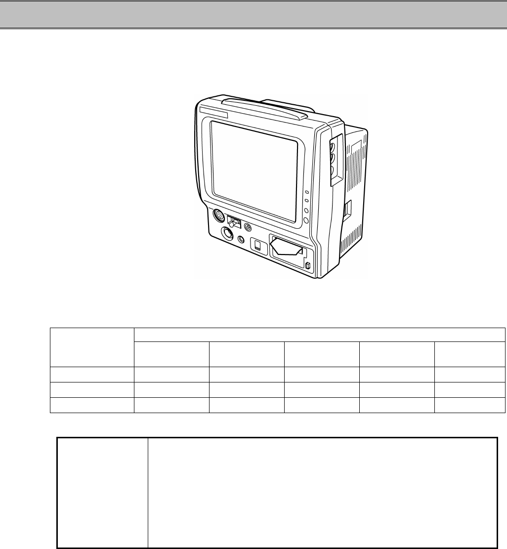
1−2
General Description
The DS-7100 system utilizes 8.4-inch color LCD display for monitoring ECG, RESP, SpO2, BP,
NIBP, TEMP measurements. Depending on the model type, CO2 measurement, telemetry
transmission, and Ethernet LAN connection are also possible.
<DS-7141>
Function
Model Type Basic
Measurement CO2
Measurement BP Telemetry
Transmission Ethernet
LAN
DS-7141 ○ ○ 2 channels ○ ○
DS-7101LT ○ × 2 channels ○ ○
DS-7101L ○ × 2 channels × ○
NOTE
The display illustration on this operation manual includes CO2
measurement, but note that CO2 measurement function is not supported
for the DS-7101L and DS-7101LT.
DS-7141 is not currently available for sales in the
United States.

1−3
Features
?
Completely self-contained, the monitor includes display part, recording part, measuring part in a
compact and lightweight package. A battery pack (optional) operation is also possible which
allows the monitor to be used as a portable monitor.
?
On the 8.4-inch color LCD display, up to 6 waveforms can be displayed. Also, the numeric
data display can be enlarged for easier view.
?
The alarm pole provided as standard indicates the alarm by 9 flashing patterns corresponding to
the alarm level.
?
All the operations are performed through the touch screen controls, and up to 4 frequently used
keys can be programmed as user key.
?
For the CO2 measurement, a microstream method is adopted which is less influenced by the
anesthetic gas. (DS-7141)
?
Through the use of telemetry transmission unit, a wireless network formation is possible.
(DS-7141,DS-7101LT)
?
Through the use of Ethernet LAN unit, a wired network formation is possible.
(DS-7141,DS-7101LT,DS-7101L)
?
No cooling fan is used, ensuring clean and quiet monitoring.
1
General Description
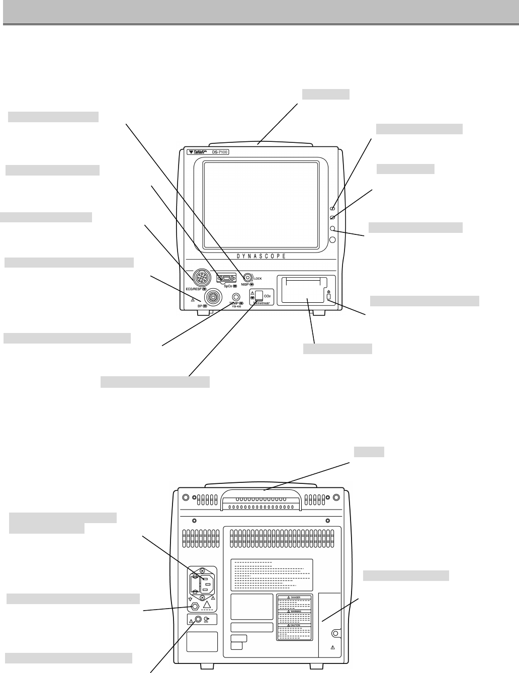
1−4
Names of Parts and Their Functions
【Front Side】
【Rear Side】
NIBP Cuff Connector
Air hose is connected here.
SpO
2
Input Connector
SpO2 relay cable (DOC-10) is
connected here.
ECG Input Connector
ECG relay cable is connected here.
BP
2ch conversion
Connector
2ch BP conversion cable is
connected here.
Temperature Input Connector
Temperature probe is connected here.
CO2 Connector(DS-7141)
CO2 sampling tube or nasal prong is connected here.
Paper Magazine
Recording paper is installed here.
Power Supply Connector
(with fuse holder)
Power cable is connected here.
(Fuse is installed in the holder.)
Equipotential Ground Terminal
Equipotential ground terminal is
connected here.
Handle
Hold this part when carrying.
Battery Pack Holder
Battery is installed here.
※We recommend the battery to be
replaced annually.
Power Supply Lamp
Indicates the main power supply.
Alarm Pole
Lights when the alarm generates.
Charge Lamp
Indicates the charge status.
Orange: Charging in process
Green: Charging complete
Ambient Light Sensor
Detects the ambient light.
Magazine Release Button
Pressing this button will release the
magazine.
Exhaust Connector (DS-7141)
Connects the gas exhausting
device and exhausts sampling gas.

1−5
【Right Side】
【Left Side】
WARNING
Do not connect unit or cable not authorized by Fukuda Denshi to any I/O
connector. If done so by mistake, the device can not deliver its maximum
performance and the connected units may be damaged, resulting in a
safety hazard.
NOTE
The display panel utilizes exclusive fluorescent light for the backlight.
Since this fluorescent light deteriorates by the life cycle, the display may
become dark, scintillate, or may not light by the long term use. In such
case, contact your nearest service representative.
PC Card Access Lamp
Indicates the PC card access status.
PC Card Slot
Insert only the specified PC card here.
Serial Connector
Connect only the specified device here.
Status Input Connector
Connect only the specified device here.
Speaker
Generates synchronous sound, key sound, alarm
sound.
Power Supply Switch
Turns the monitor power ON or OFF.
LAN Connector
Branch cable (CJ-522) is connected here for
wired network.
1
Names of Parts and Their Function
Side Cover (for maintenance)
Do not open this cover. This cover is for
maintenance only, which is to be performed by
our service representative.
1−6
Blank Page