Japan Radio Co NKE2632 Solid State S-Band Marine Radar User Manual Installation Manual Part 6
Japan Radio Co Ltd. Solid State S-Band Marine Radar Installation Manual Part 6
Contents
- 1. Installation Manual Part 1
- 2. Installation Manual Part 2
- 3. Installation Manual Part 3
- 4. Installation Manual Part 4
- 5. Installation Manual Part 5
- 6. Installation Manual Part 6
- 7. Installation Manual Part 7
- 8. Installation Manual Part 8
- 9. Installation Manual Part 9
- 10. Installation Manual Part 10
- 11. Installation Manual Part 11
- 12. Instruction Manual Operation Part 1
- 13. Instruction Manual Operation Part 2
- 14. Instruction Manual Operation Part 3
- 15. Instruction Manual Operation Part 4
- 16. Instruction Manual Funtion Part 1
- 17. Instruction Manual Funtion Part 2
- 18. Instruction Manual Funtion Part 3
- 19. Instruction Manual Funtion Part 4
- 20. Instruction Manual Funtion Part 5
- 21. Instruction Manual Funtion Part 6
Installation Manual Part 6
3 Installation of Display Unit > 3.14 Other Labels
3-147
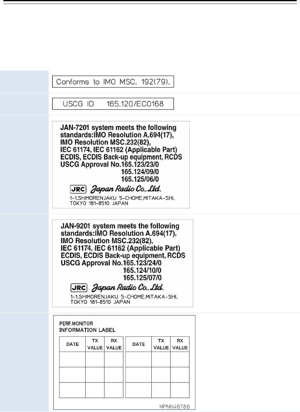
3.14 Other Labels
Labels listed below are attached on the CCU:NCM-928. Please stick the labels which corresponds to the
model name on the top of CCU as follows instruction.
IMO label
It is required for any type of
RADAR.
USCG label for
JMR-9200
Only JMR-9200 series RADAR
use it.
USCG label for
JAN-7201
Only JAN-7201 ECDIS use it.
USCG label for
JAN-9201
Only JAN-9201 ECDIS use it.
INFORMATION
LABEL
It is required for any type of
RADAR.
In the case of standalone type,
stick it on the front cover.
In the case of flush mount or
desktop type, stick it on that is
easy to see it such as the front
cover of the console or the cover
of JB.
These are not necessary for JAN-9202 Conning Display and JAN-7202 Conning Display.
3 Installation of Display Unit > 3.14 Other Labels
3-148
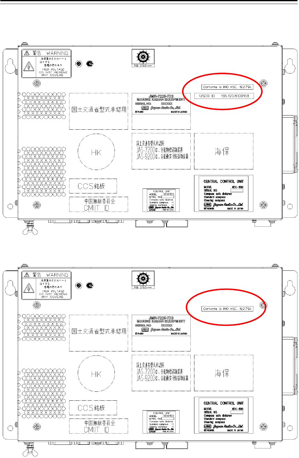
3.14.1 Position of labels
3.14.1.1 JMR-9200 series Radar
3.14.1.2 JMR-7200 series Radar
3 Installation of Display Unit > 3.14 Other Labels
3-149
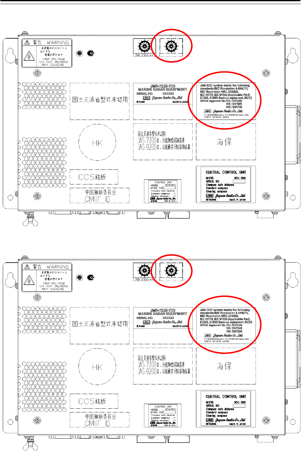
3.14.1.3 JAN-9201
3.14.1.4 JAN-7201
3 Installation of Display Unit > 3.14 Other Labels
3-150
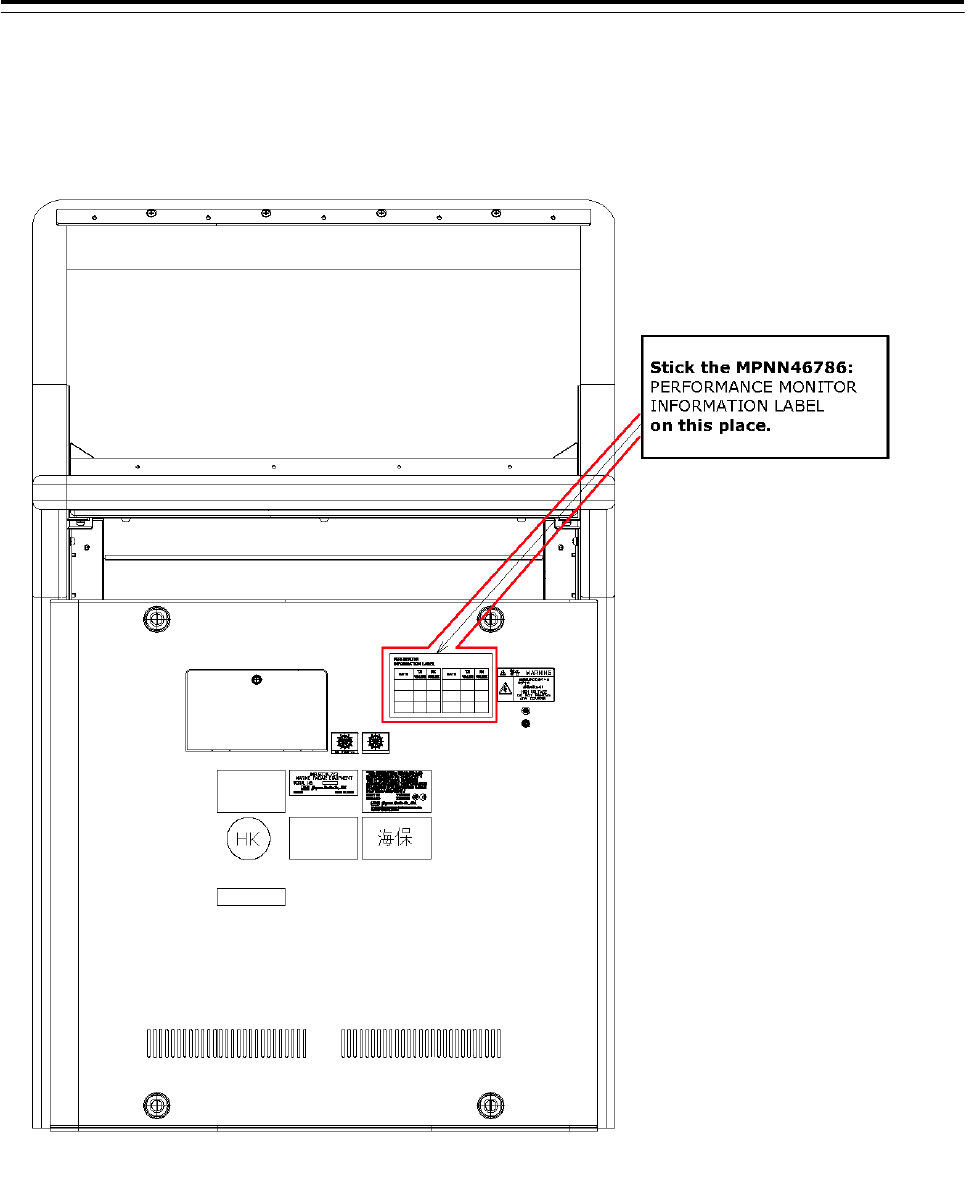
3.14.1.5 Information Label
In case of the standalone type, stick the information label to the front cover.
In case of the desktop type or flush mount type, stick the information label to the easy to read position.
(etc. Cover of the NQE-1143 Junction box, front panel of the console.
4-1
4. Initial Setting
Never have the equipment adjusted by unauthorized service personnel.
If the equipment is set up incorrectly, it may cause unstable operation.
Never make adjustments while navigating. Doing so may adversely
affect the radar functions, causing accidents and/or malfunctions.
Before moving on to communication and sensor settings, confirm that
the operation shown in "3.7 Connection with Sensors" is complete.
Memo
RADAR, ECDIS, or Conning as the task station that needs the setting is indicated, following each
section title.
[RADAR/ECDIS/Conning] The setting is necessary for the respective task stations.
[ALL] The setting is necessary for all the task stations.
However, some settings are reflected in all other task stations once they are set in one station. Refer
to "4.1 Service Menu".
4-2
4.1 Service Menu
[ALL]
Use the Service menu to make initial settings for the equipment.
The Service menu consists of three submenus of Adjustment, Installation and Maintenance. To display
the Service menu, a password is required.
Flow of equipment initial settings
Equipment setting items include setting items that are common among task stations (RADAR, ECDIS,
and Conning Display) and setting items that are specific to each task station. Once a common item is
set in one task station, the setting is reflected in other task stations also (initial setting synchronization).
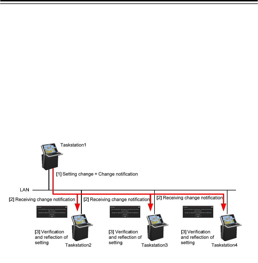
Initially, the mechanism of synchronization of common setting items among the task stations is
described below.
1 Set the setting items.
Set a setting item in a task station.
2 Notify the change of the setting item.
The change of the setting is notified to other task stations that are connected to the network.
3 Reflect the change of the setting item.
The task station that received the change notification updates the common setting items and
when the task is restarted, the change is reflected in the own task station.
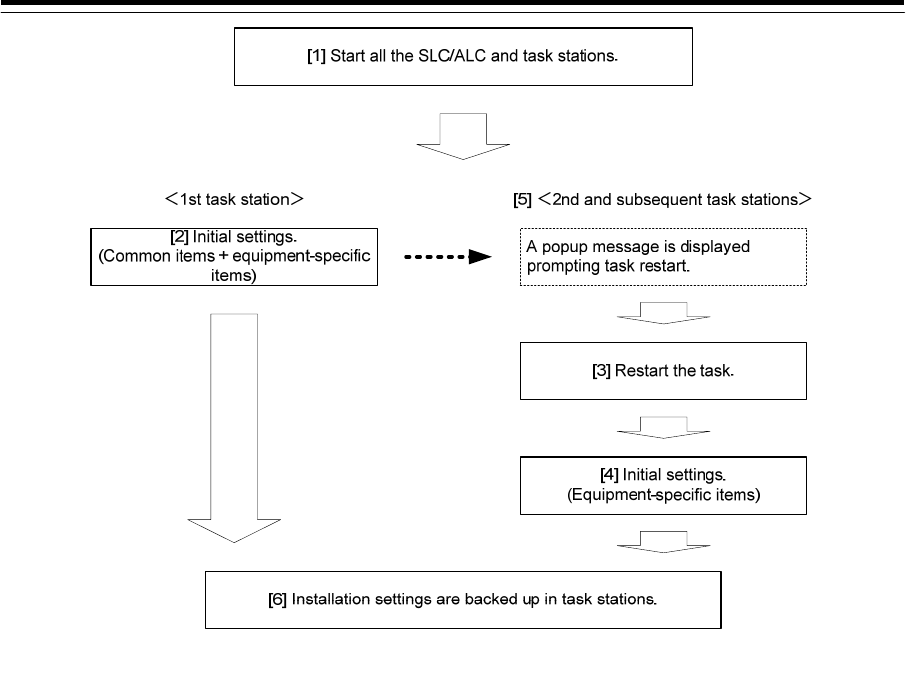
The flow of equipment initial settings is shown below.
4-3
1 Start all the SLC/ALC and task stations.
By setting the common setting items while all the task stations are active, the common setting
items are synchronized through all the task stations.
2 Initialize the 1st task station (task station that is displayed as Master in the Control
Status).
In the 1st task station, set common setting items and equipment-specific setting items.
3 Re-activate the task before initializing the 2nd task station (task station that is
displayed as Slave in the Control Status).
When an initial setting item is set in the 1st task station, a message is displayed prompting the
restart of the task on other task stations. When the message is closed, the tasks are restarted
and the common setting items are reflected.
4 Perform initial setting of the 2nd task station.
In the 2nd task station, set an equipment-specific setting item. When a setting screen of the
common setting item is displayed on other stations, the common setting item is displayed in
the edit disabled state. By maintaining the display of the setting screen (Installation – System
Configuration, etc.) after completing the 1st task station, unintended change of the common
setting item can be prevented.
5 Perform steps 3 and 4 for the remaining task stations.
6 Back up the equipment settings in each task station.
Refer to “4.42 Backup of Data”.
The setting screen with common setting items can display the status information as to whether the own
station can edit common setting items. When own task station can edit common setting items, "Master"
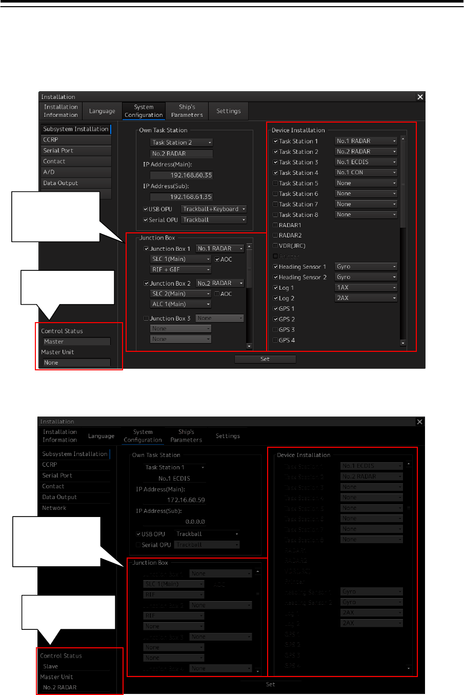
4-4
is displayed in Control Status and when display/editing is being performed in other task stations,
"Slave" is displayed and the common setting items are displayed in the edit disabled state.
Common setting items can be edited on own task station
Common setting items cannot be edited on own task station
"Master" is displayed
in Control Status
Common setting
items can be edited
"Slave" is displayed in
Control Status
Common setting
items cannot be
edited
4-5
Setting screens containing common setting items are listed below. For the details of common setting
items, refer to “4.43 List of Common Setting Items”.
Setting screen Description
Installation – System Configuration Equipment information and communication settings are
common setting items.
Installation – Ship’s Parameters The settings of own ship’s parameters are common
setting items.
Maintenance – Initialization Although there is no setting item, common setting items
are initialized by initialization of service setting.
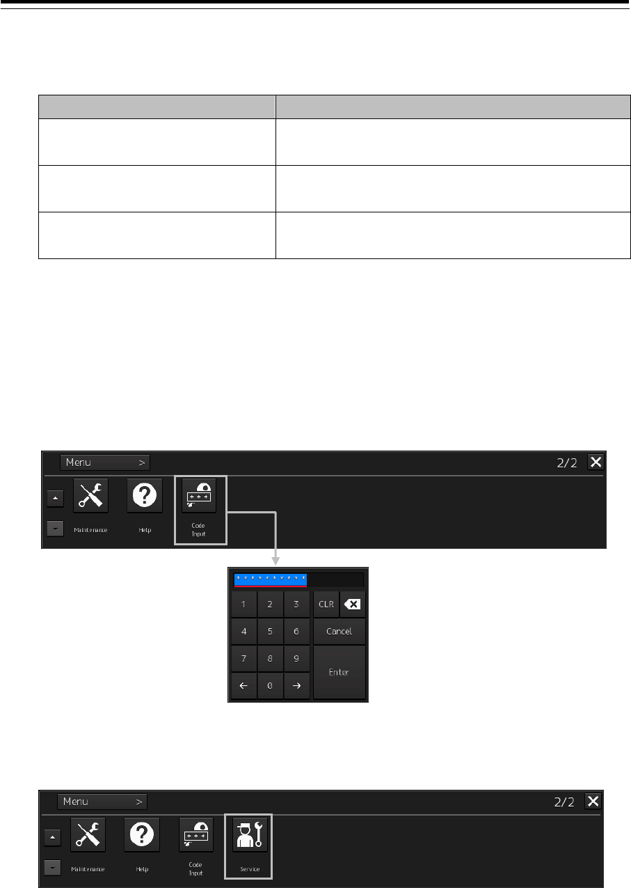
Displaying the Service menu
1 Click on the [Menu] button on the left toolbar.
The menu is displayed.
2 Click the [Code Input] button on the menu.
The password input dialog is displayed.
3 Enter 0009 in Password.
The [Service] button is added to the menu. Once the [Service] button has been added, the
button is continuously displayed until the task menu is closed.
4 Click on the [Menu] button on the left toolbar.
The menu is displayed.
4-6
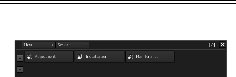
5 Click the [Service] button.
The submenu is displayed.
6 Display a submenu dialog box by clicking on one of the [Adjustment], [Installation],
and [Maintenance] buttons.
4-7
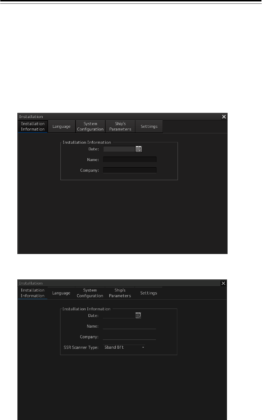
4.2 Installation Information
[ALL]
Use the "Installation Information" dialog box to verify the installation of this equipment and perform the
initial setting.
Displaying the "Installation Information" dialog
1 Display the dialog of the Installation submenu.
2 Select [Installation Information] in the Classification pane.
The "Installation Information screen" dialog is displayed in the Edit/Result pane.
Using a magnetron radar or the current solid-state radar and ECDIS/Conning
Using a compact solid-state radar

4-8
Entering an installation date and a time
1 Click on the calendar button in the [Date] input box.
A calendar is displayed.
2 Set a year and a month by using the year selection spin button and the month
selection spin button.
3 Click on the date to be set from the date selection box.
The setting is completed and the calendar is closed.
Entering an installer name
1 Click on the [Name] input box.
A character input keyboard is displayed.
2 Enter an installer name (up to 32 characters).
Entering an installing company
1 Click on the [Company] input box.
A character input box is displayed.
2 Enter an installing company (up to 32 characters).
Selecting a solid-state radar type (using a compact solid-state radar)
1 Select one of the following radar types from the [SSR Scanner Type] combo box.
Sband 8ft
Sband 8ft-HS
Sband 12ft
Unselected (when initial setting has not been performed)
4-9
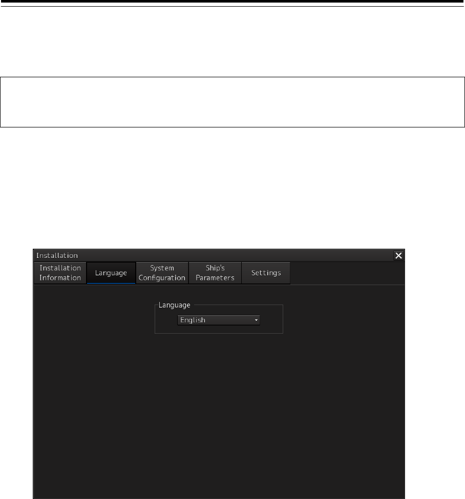
4.3 Setting Up a Language [ALL]
Use the "Language" dialog to set up the language to be used for screen display of this equipment.
Note
As of now, the current language cannot be changed. Other languages will be supported in the future.
Displaying the "Language" dialog
1 Display the dialog of the Installation submenu.
2 Select [Language] in the Classification pane.
The "Language" dialog is displayed in the Edit/Result pane.
Setting up a language
1 Select the language to be used from the [Language] combo box.
4-10
4.4 Subsystem Installation
[ALL]
Use the "Subsystem Installation" dialog to verify and change the subsystem configuration of this
equipment.
Displaying the "Subsystem Installation" dialog
1 Display the dialog of the Installation submenu.
2 Select [System Configuration] in the 1st Classification pane and [Subsystem
Configuration] in the 2nd Classification pane.
The "Subsystem Installation" dialog is displayed in the Edit/Result pane.

4-11
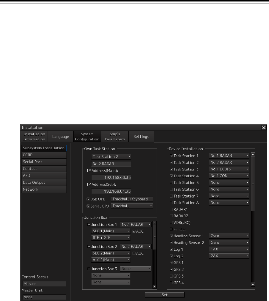
Changing the subsystem configuration
Set the following items in the "Subsystem Installation" dialog.
If the presence/absence of the equipment is set in this dialog, the menu display/hide and configuration
contents relating to the equipment change according to the setting contents.
Setting item Description of setting Setting value
Own Task Station Select the Task Station number of the equipment from
the combo box.
Select from the task stations that were set in Task
Stations 1 to 8 of Device Installation.
Task Station 1 ~ Task Station 8
Select installation/non-installation of the USB OPU
(Operation Unit) by using the [USB OPU] check box.
When the unit is installed, select the installation
contents in the [USB OPU] combo box.
Memo
When OPU is installed, the OPU active/inactive
monitoring is performed. When there is no response,
the following alert is displayed and OPU is restarted.
OPU: OPU-USB(Communication error)
Keyboard: OPA-OPB(Communication error)
Installation/non-installation of
the unit
Absent: Clear
Present: Select
Installation contents
No keyboard operation unit
(optional):
Select Trackball.
Keyboard operation unit
(optional):
Select Trackball + Keyboard.
Select the installation/non-installation of Serial OPU
(Operation Unit) by using the [Serial OPU] check box.
When OPU is installed, select the installation contents
in the [Serial OPU] combo box.
Memo
When OPU is installed, the OPU active/inactive
monitoring is performed. When there is no response,
the following alert is displayed and OPU is restarted.
OPU: OPU-Serial(Communication error)
Keyboard: OPA-OPB(Communication error)
Installation/non-installation
Non-installation: Clear
Installation: Select
Installation contents
No keyboard operation unit
(optional):
Select Trackball.
Keyboard operation unit
(optional):
Select Trackball + Keyboard.
Junction Box Select installed/not installed of junction boxes 1 to 8
from the [Junction Box 1 ~ 8] check boxes.
Not installed: Clear.
Installed: Select.
In the combo box for selecting a Task Station, select
the equipment that is directly connected to Radar I/F
or Gyro I/F of the junction box.
Equipment that is assigned to
any of Task Stations 1 to 8 of
Device Installation
Select the equipment to be installed in the Junction
Box that was selected from [Junction Box 1 ~ 8] check
boxes.
None
SLC 1 to 8(Main)
SLC 1 to 8(Sub)
ALC 1 to 8
RIF
GIF
RIF + GIF
When SLC is selected from the combo box, select
installed/not installed of AOC with the [AOC] check
box.
Memo
When “Installed” is set while AOC is not installed,
the message “SLC AOC Error” is displayed.
Not installed: Clear.
Installed: Select.

4-12
Setting item Description of setting Setting value
Device Installation Select installed/not installed of the device by using the
check box of each subsystem.
For the subsystem that is installed, select the
parameters from the combo box.
No restrictions are placed on the order of assigning
the devices to Taskstation1-Taskstation8.
The following shows an example of device assignment
to task stations:
(Example) Device assignment in ascending order of
the values of IP-address 4th octets
(Refer to 4.11 "JRC Network IP Address.")
1: No.1 RADAR
2: No.2 RADAR
3: No.1 ECDIS
4: No.2 ECDIS
5: No.1 CON
Note:
The subsystems that are displayed as disabled will be
supported in the future.
Not installed: Clear.
Installed: Select.
Subsystem
Task Station 1~Task Station 8
RADAR 1, 2 *1
VDR(JRC)
Primer
Heading Sensor 1, 2
Log 1, 2
GPS 1~4
Ship’s Clock
Echo Sounder (T/D 1~4)
AIS
NAVTEX
Anemometer
Water TEMP Meter
Current Meter
Climate Meter
Autopilot
Rudder
Engine/Propeller
Engine Telegraph
Bow Thruster
Stem Thruster
Azimuth Thruster
Generator
Fin Stabilizer
YEOMAN Digitizer
Radar Simulator
S-JOY 1 to 5
GPS Selector
Log Selector
Inmarsat-C 1, 2
(*1) For ECDIS, the communication radar is to be checked. If this check box is checked, the TT data
over the LAN is received from a device that is assigned to No.1 RADAR for RADAR1 and No.2 RADAR
for RADAR2. However, if it is set to receive the TT data from the serial port by the setting of "Serial
Port", the TT data is received from the serial port. For the setting of "Serial Port", refer to “4.6 Setting
Up a serial Port”.
Table 4-1 Device numbers that can be selected
No. Device numbers that can be selected No. Device numbers that can be selected
1 None 12 No.3 ECDIS
2 No.1 RADAR 13 No.4 ECDIS
3 No.2 RADAR 14 No.1 CON
4 No.3 RADAR 15 No.2 CON
5 No.4 RADAR 16 No.1 CON (Wing)
6 No.5 RADAR 17 No.2 CON (Wing)
7 No.6 RADAR 18 No.1 CON (Remote)
4-13
8 No.7 RADAR 19 No.2 CON (Remote)
9 No.8 RADAR 20 No.1 RPS
10 No.1 ECDIS 21 No.2 RPS
11 No.2 ECDIS
Note
Do not select the same Task Station number of Own Task Station among multiple devices. If
the same Task Station number is selected among multiple devices, unintended operation is
performed.
When performing radar overlay without installing interswitch, do not forget to check Device
Installation systems RADAR1 and RADAR2 (when two radar systems are available). When
interswitch is installed and available for use, radar overlay can be performed regardless of the
setting of RADAR1 and RADAR2. For the setting of interswitch, refer to “4.16 Setting
Interswitch”.
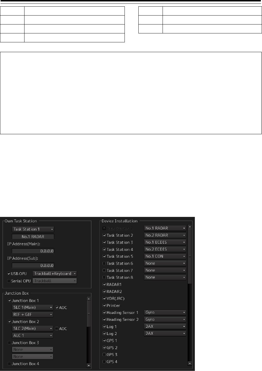
Setting example
The following diagram shows the setting example of [Own Task Station] and [Device Installation] when
the subsystem is configured as follows:
No.1 RADAR (S band radar) as Task Station 1
No.2 RADAR (X band radar) as Task Station 2
No.1 ECDIS as Task Station 3
No.2 ECDIS as Task Station 4
Conning as Task Station 5
4-14
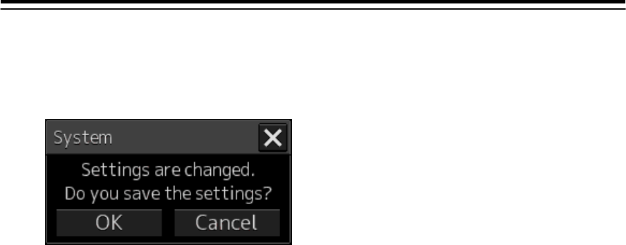
Saving subsystem configuration changes
1 Click on the [Set] button in the "Subsystem Installation" dialog.
A dialog is displayed prompting confirmation of saving the configuration changes.
2 To save the changes, click on the [OK] button. To cancel the changes, click on the
[Cancel] button.
4-15
4.5 Setting Up CCRP (Consistent
Common Reference Point) [ALL]
Set a measurement reference position (CCRP) on own ship by using the "CCRP" dialog.
Displaying the "CCRP" dialog
1 Display the dialog of the Installation submenu.
2 When you select [System Configuration] in the 1st Classification pane and [CCRP] in
the 2nd Classification pane
The "CCRP" dialog is displayed in the Edit/Result pane.
Note
Configure the GPS setting correctly. The latitude/longitude data that is received from GPS is
corrected and displayed as the latitude/longitudie of own ship.

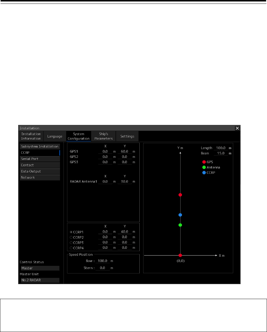
4-16
Setting CCRP
Set the following items in the "CCRP" dialog.
Setting Item Description of Setting Setting Value
Length (of ship) Enter the ship's length in the box. 1.0 to 1022.0m
Beam (ship's width) Enter the ship's width in the box. 1.0 to 126.0m
GPS1/2/3/4 Enter the equipment positions of GPS1, GPS2,
GPS3 and GPS4 in the boxes.
X: X axes of GPS1/2/3/4
Y: Y axes of GPS1/2/3/4
Note
• If "No Equipment" is specified in the
Subsystem Installation panel, this is not
displayed.
• When the input range is changed by modifying
[Length] and [Beam], if a value exceeding the
input range after modifying has already been
entered, the value will be corrected to the
maximum or minimum value.
Changes depending on the
value of [Length] and [Beam].
If Length=a and Beam=b:
X -b/2 to b/2
Y 0.0 to a
For example,
• if Length=1.0 and Beam=1.0:
X -0.5 to 0.5
Y 0.0 to 1.0
• if Length=700.0 and
Beam=70.0:
X -35.0 to 35.0
Y 0.0 to 700.0
Radar Antennas1 to 8
(equipment positions of
radar antennas1 to 8)
Enter the equipment positions of Radar
Antennas1 to 8 in the boxes.
X: X axes of radar antennas 1 to 8
Y: Y axes of radar antennas 1 to 8
Note
• If "No Equipment" is specified in the [DipSW]
settings of the interswitch unit, this is not
displayed.
• When the input range is changed by modifying
[Length] and [Beam], if a value exceeding the
input range after modifying has already been
entered, the value will be corrected to the
maximum or minimum value.
CCRP1/2/3/4 Enter the positions of CCRP1 to CCRP4 of the
ship in the boxes.
X: X axes of CCRP1/2/3/4
Y: Y axes of CCRP1/2/3/4
Note
When the input range is changed by modifying
[Length] and [Beam], if a value exceeding the
input range after modifying has already been
entered, the value will be corrected to the
maximum or minimum value.
CCRP Select the position to be used as the ship's
CCRP by clicking the applicable button.
Note
Normally, only CCRP1 is used.
CCRP1
CCRP2
CCRP3
CCRP4
Speed Position Bow Enter the distance from the origin (0, 0) to the
display point of the right/left ship speed on the
Bow side.
0.0 to Ship’s length m
Speed Position Stern Enter the distance from the origin (0, 0) to the
display point of the right/left ship speed on the
Stern side.
0.0 to Ship’s length m
4-17
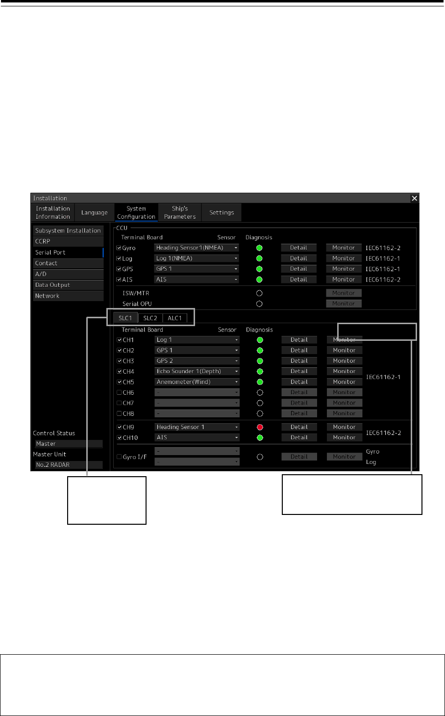
4.6 Setting Up a Serial Port [ALL]
Use the "Serial Port" dialog to verify the setting of the serial port of this equipment and perform the
initial setting. The status of ISW/MTR and Serial OPU can also be monitored.
Displaying the "Serial Port" dialog.
1 Display the dialog of the Installation submenu.
2 Select [System Configuration] in the 1st Classification pane and [Serial Port] in the
2nd Classification pane.
The "Serial Port" dialog is displayed in the Edit/Result pane.
[Diagnosis] lamp light colors
The [Diagnosis] lamp displays the diagnosis result as to whether the sentence of the specified sensor
is received for each serial port and also displays the status of ISW/MTR and Serial OPU.
Lit in red: Data not received.
Lit in green: Data is receiving.
Lit in orange: In diagnosis (before decision).
No color: Serial port is disabled.
Note
When the RADAR slave mode is active, the [Diagnosis] lamp of ISW/MTR is disabled.
When the [Serial OPU] check box is set to Off after selecting [Service]-[Installation]-[System
Configuration]-[Subsystem Installation], the [Diagnosis] lamp of serial OPU is disabled.
Tab name
SLC1~8(M)/
SLC1~8(S)/
ALC1~8
Is displayed only if the SLC1 ~ 8 (S).
Refer to "For making SLC(Main) and
SLC(Sub) the same setup".
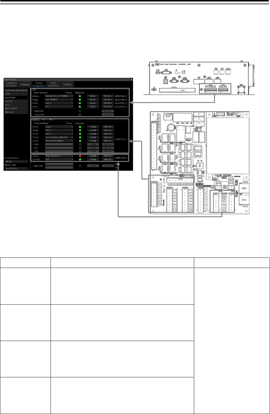
4-18
Setting a serial port
In the "Serial Port" dialog, allocate the sensor to be connected for the serial port on CCU and the serial
port on SLC(Main/Sub)/ALC.
[Setting a serial port on CCU]
Setting Item Description of Setting Setting Value
Gyro 1. Select the check box and enable the serial port for the
Gyro.
2. Select the sensor to be connected to the Gyro serial
port from the [Sensor] combo box. When no sensor is
selected, select [-].
To enable: Select.
To disable: Clear.
The sensors that can be
selected vary according to
the subsystem installation
status. Refer to "Table 4-2
Sensors that can be selected
on the Task Station".
LOG 1. Select the check box and enable the serial port for the
LOG.
2. Select the sensor to be connected to the LOG serial
port from the [Sensor] combo box. When no sensor is
selected, select [-].
GPS 1. Select the check box and enable the serial port for the
GPS.
2. Select a sensor to be connected to the serial port for
the GPS from the [Sensor] combo box. When no
sensor is selected, select [-].
AIS 1. Select the check box and enable the serial port for the
AIS.
2. Select a sensor to be connected to the serial port for
the AIS from the [Sensor] combo box. When no sensor
is selected, select [-].
Serial port setting on CCU
Serial port setting on SLC/ALC
CCU
SLC/ALC

4-19
Table 4-2 Sensors that can be selected on CCU
Serial port Sensor name
Devices required as the subsystem
(set to "installed" in the "Subsystem
Installation" dialog)
Gyro Heading Sensor(NMEA) Heading Sensor 1
Heading Sensor(Gyro I/F)
LOG Log(NMEA) Log 1
Log(Gyro I/F) *1
Selector Log Selector
GPS GPS 1 GPS 1
GPS 2 GPS 2
GPS 3 GPS 3
GPS 4 GPS 4
Selector GPS Selector
AIS AIS AIS
(*1) Can be selected only when "Heading Sensor (Gyro I/F)" is selected for the Gyro port.
When "Log(Gyro I/F)" is selected, log data is acquired together with the Heading Sensor data from the Gyro
port and communication is not performed through the LOG port. Therefore, the Diagnosis lamp, the Detail
button, and the Monitor button are disabled.
[Setting serial ports on the SLC/ALC that is installed]
Setting Item Description of Setting Setting Value
CH1 to CH8
(IEC-61162-1)
1. Click on any of SLC1(M) to SLC8(M), SLC1(S) to
SLC8(S) and ALC1 to ALC8 tabs.
2. Enable the serial port of the channel by selecting
the check box.
3. Select the sensor to be connected to the channel
from the [Sensor] combo box. When no sensor is
selected, select [-].
To enable: Select.
To disable: Clear.
The sensors that can be selected
vary according to the subsystem
installation status. Refer to "Table
4-3 Sensors that can be selected on
SLC/ALC".
CH9/CH10
(IEC-61162-2)
1. Click on any of SLC1(M) to SLC8(M), SLC1(S) to
SLC8(S) and ALC1 to ALC8 tabs.
2. Enable the serial port of the channel by selecting
the check box.
3. Select the sensor to be connected to the channel
from the [Sensor] combo box. When no sensor is
selected, select [-].
Gyro I/F Items are displayed only for SLC + "GIF" "RIF+GIF"
in Gyro I/F.
1. Click on any of SLC1(M) to SLC8(M) and
SLC1(S) to SLC8(S) tabs.
2. Enable the serial port of the channel by selecting
the check box.
3. Select the sensor (Gyro and Log) to be
connected to the channel from the [Sensor]
combo box. When no sensor is selected, select
[-].
To enable: Select.
To disable: Clear.
Sensors that can be selected:
Gyro: Heading Sensor 1/2
Log: Log 1/2
* The sensors that can be selected
vary according to the subsystem
installation status.

4-20
Table 4-3 Sensors that can be selected on the SLC/ALC
Sensor name Devices required as the subsystem (set to "installed" in the
"Subsystem Installation" dialog)
Heading Sensor 1 Heading Sensor 1
Heading Sensor 2 Heading Sensor 2
Log 1 Log 1
Log 2 Log 2
GPS 1 GPS 1
GPS 2 GPS 2
GPS 3 GPS 3
GPS 4 GPS 4
Ship’s Clock Ship’s Clock
Echo Sounder(Depth) Echo Sounder(Depth)
AIS AIS
NAVTEX NAVTEX
Anemometer(Wind) Anemometer(Wind)
Water Temperature Meter Water Temperature Meter
Current Meter Current Meter
Climate Meter Climate Meter
TRI *1 TRI
Autopilot Autopilot
Rudder Rudder
Engine/Propeller Engine/Propeller
Engine Telegraph Engine Telegraph
Thruster Thruster
Azimuth Thruster Azimuth Thruster
Generator Generator
Fin Stabilizer Fin Stabilizer
YEOMAN Digitizer YEOMAN Digitizer
RADAR1(TT RX) RADAR1
RADAR2(TT RX) RADAR2
Other than sensors
Alert(to CAM) *2
Alert(from Subsystem) *2
Alert(to BNWAS) *2
IAS(NMEA) *2
DSC *2
- *3
(*1) TRI (Turn Rate Indicator): Indicates a device that transmits ROT.
(*2) Used for alert handling. For details, refer to "4.8 CAM Configuration and Setting".
4-21
(*3) In the case of the port used for a data output, it is used.
Refer to "4.10 Setting Data Output".
[port settings for data output]
[CHx] check box : Select to enable.
[Sensor] combo box : “-”
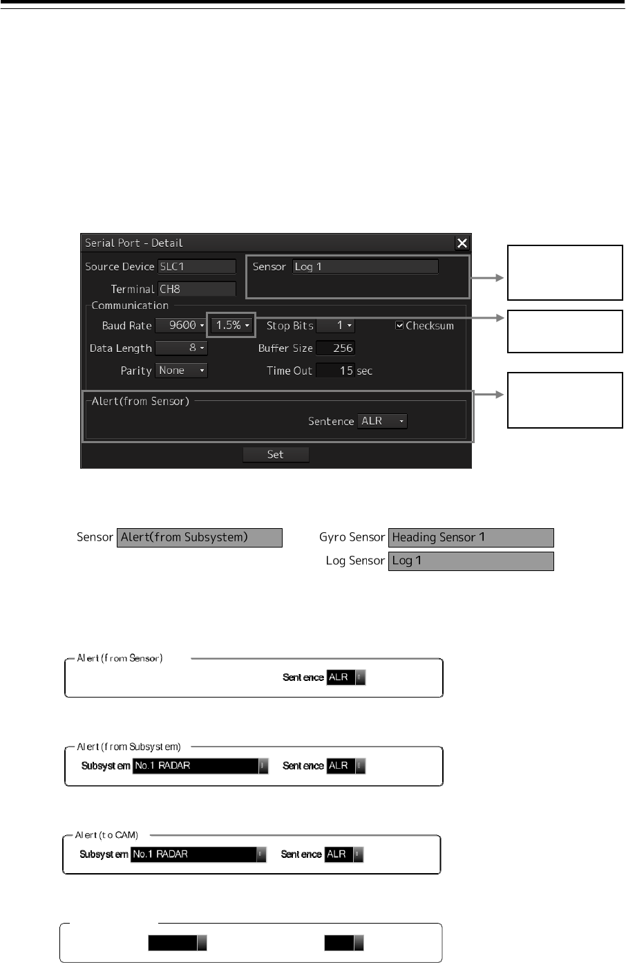
To change the communication settings of the Serial Port
1 Click the [Detail] button of the enabled serial port and display the [Detail] dialog.
(*1) Sensor name display pattern
[For sensor other than SLC Gyro I/F] [For SLC Gyro I/F]
(*2) Display pattern of alert handling setting
[Various sensors (*1)]
(*1) Other than "Alert(from Subsystem / to CAM / to BNWAS)", and "DSC"
[When the sensor is "Alert(from Subsystem)"]
[When the sensor is "Alert(to CAM)"]
[When the sensor is " Alert(to BNWAS)"]
[When the sensor is "DSC", or "- (not selected)"]
No display
Alert(to BNWAS)
AMSAccess Source ▼Sentence ALR ▼
For SLC Gyro I/F,
sensor names are
displayed in two
lines. (*1)
Displayed only for
SLC CH8-CH10
Alert handling
setting (*2)

4-22
2 Perform the settings shown in the following table and then click on the [Set] button.
Setting Item Description of Setting Setting Value
Baud Rate Select the baud rate of the corresponding serial
port from the combo box.
In the [Detail] dialog of CH8 to CH10, the [Baud
Rate] addition ratio combo box is displayed on
the right side of the [Baud Rate] combo box.
Selectable baud rates vary
depending on the serial port
(refer to "Table 4-4
Selectable baud rates").
[Baud Rate] addition ratio
combo box
The combo box is displayed in the [Detail] dialog
of AIS, GYRO *1, and CH8 to CH10. The addition
ratio (%) for adjusting the baud rate can be
changed in the combo box. The baud rate that is
used for communication is the value obtained by
adding the addition ratio set here to the value
that is set in the [Baud Rate] combo box.
Example) 4800 × (1 + 1.5/100) = 4872
Addition ratio
<Adjustment method>
At first, use 1.5% as the addition ratio. If data
cannot be received, decrease it in decrements of
0.5%.
(*1) Only when selection of a sensor is other than
"Heading Sensor 1/2(Gyro I/F)".
0.0% to 3.0% (Can be set in
the unit of 0.5%)
Data Length Select the data length of the corresponding serial
port from the combo box.
5/6/7/8
Parity Select the parity of the corresponding serial port
from the combo box.
None/Odd/Even
Stop Bits (Stop Bit Length) Select the stop bit length of the corresponding
serial port from the combo box.
1/2
Buffer Size Enter the buffer size of the corresponding serial
port in the box.
0 to 10240 bytes
Time Out Enter the time-out duration of the corresponding
serial port on the box.
0 to 999sec
Checksum Select the check box and enable the checksum
of the sentence of the corresponding serial port.
To enable: Select.
To disable: Clear.
Subsystem This item is displayed only when "Alert(from
Subsystem)" or "Alert(to CAM)" is selected as
the sensor.
Select a device for alert handling. For details,
refer to "4.8 CAM Configuration and Setting."
Subsystem installed (task
station and sensor)/BNWAS
Primary/Secondary Displayed only when "IAS(MODBUS)" is
selected for the sensor.
Set Primary/Secondary for the input from IAS.
Primary / Secondary
Sentence Set the type of alert sentence.
If "-" is selected, no alert checks are made.
-/ALR/ALF
* The selection of "-"
indicates that the type of
alert sentence is
unselected; it can be
selected only for general
sensors (e.g., GPS and
Log).
Access Source Displayed only when "Alert(to BNWAS)" is
selected for the sensor.
Select the equipment that communicates with
BNWAS.
When the system configuration does not contain
CAM, select ECDIS. In other cases, select AMS.
AMS/ECDIS

4-23
Table 4-4 Selectable baud rates
Serial port Baud rate
Serial port on CCU
Gyro (when Heading Sensor (NMEA) is selected) 4800/38400
Gyro (when Heading Sensor (Gyro I/F) is
selected)
Fixed to 38400
Log (when Log (NMEA) is selected) Fixed to 4800
GPS Fixed to 4800
AIS Fixed to 38400
Selector Fixed to 4800
Serial port on SLC/ALC
CH1-8 2400/4800/9600
CH9/10 2400/4800/9600/19200/38400
Gyro I/F Fixed to 38400
Note
In the case of the serial port which assigned "IAS (NMEA)", carry out network transmission
setting of Primary(connects to SLCx(Main)), and Secondary (connects toSLCx(Sub)) to the
same setup.
For making SLC(Main) and SLC(Sub) the same setup
A setup of SLC(Sub) can be changed into the contents set up by SLC(Main).
When there is connection which is different by SLC(Main) and SLC(Sub), after performing this
operation, it changes individually.
1 The tab of SLCx(S) which sets up is chosen.
2 Click the "Same as SLCx (Main)" button.
The preset value of SLCx(Sub) is changed into the same contents as SLCx(Main).
Checking the communication status
The communication status can be displayed in order to see if serial port communication is being
performed normally.
[Line Monitor] and [Packet Monitor] are available to display the communication status.
Line Monitor: Displays the serial port communication data.
Packet Monitor: Displays the LAN communication status between the SLC/ALC and this equipment.
(Only for SLC/ALC serial ports)
Memo
For the sentence format, refer to "Chapter 6 Sentence Format."
When communication statuses are displayed on multiple equipment units through one port,
and any of the equipment unit stopped monitoring, monitoring has stopped by all the
equipment units. In this case, restart monitoring.
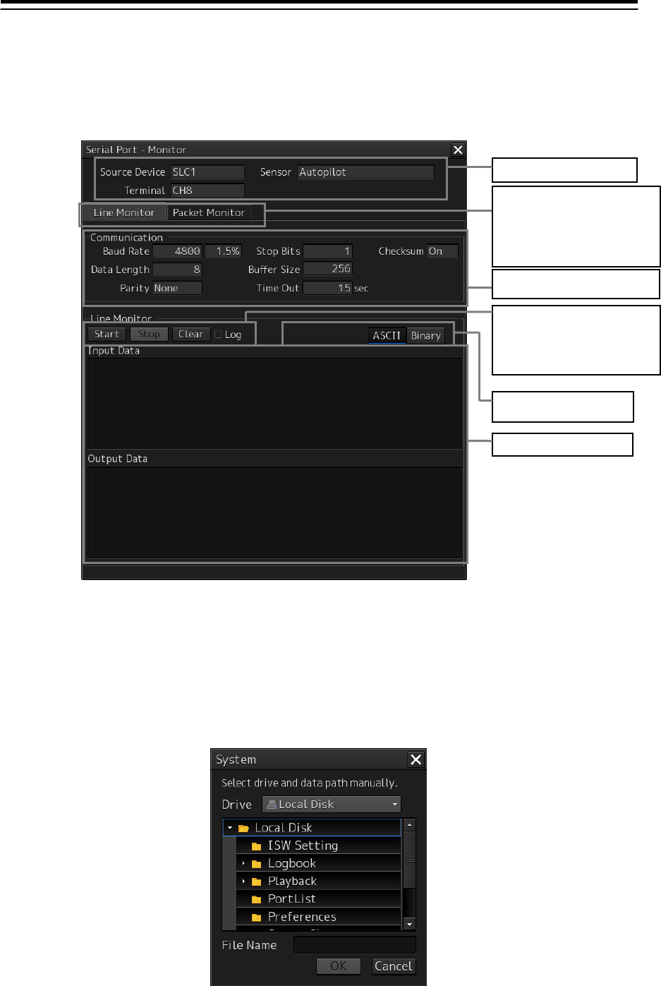
4-24
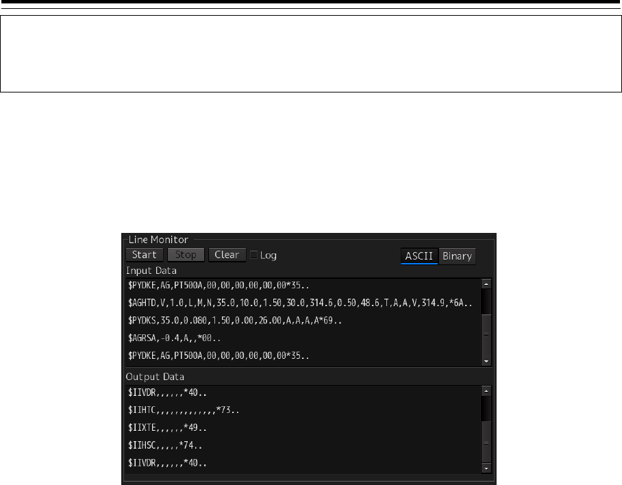
Line Monitor
1 Click on the [Monitor] button of the enabled serial port to display the "Monitor" dialog
box.
2 Click on the [Start] button to start monitoring.
Monitoring will be started. If communication is being performed, the communication data is
displayed in the [Input Data] and [Output Data] areas.
To save the monitoring data in a log file, select the [Log] check box, and then click on the [Start]
button. A dialog box is displayed for selecting the file to be saved.
Enter the file name and click on the [OK] button. Monitoring will be started.
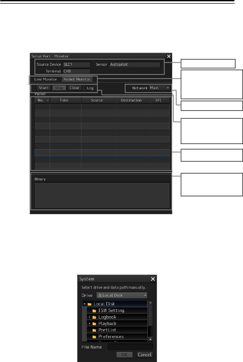
Selected port information
Selection of serial
communication monitor or
packet monitor
(Packet Monitor can be
selected only for SLC/ALC
ports.)
Serial communication setting
information
Start/stop of monitoring,
clearing of the monitoring
data, and specification that
saves data in a log file at the
start of monitoring
Monitoring data
Selection of display
format
4-25
Memo
Data saved in a log file is limited to 5MB. When the data size has reached the limit, the save
processing is stopped automatically.
To change the data display format, select [ASCII] or [Binary], and then click on the [Start]
button. The data display format currently displayed can also be changed after monitoring is
complete.
<Monitoring data display example>
3 Click on the [Stop] button to stop monitoring.
4-26
Packet Monitor
1 Click on the [Monitor] button of the enabled serial port to display the "Monitor" dialog
box, and click on the [Packet Monitor] tab.
2 Click on the [Start] button to start monitoring.
Monitoring will be started. If communication is being performed, the packets received are
displayed in the packet list.
To save the monitoring data in a log file, select the [Log] check box, and then click on the [Start]
button. A dialog box is displayed for selecting the file to be saved.
Enter the file name and click on the [OK] button. Monitoring will be started.
Selected port information
Selection of serial
communication monitor or
packet monitor
(Packet Monitor can be
selected only for SLC/ALC
p
orts.
)
Start/stop of monitoring,
clearing of the monitoring
data, and specification that
saves data in a log file at the
start of monitoring
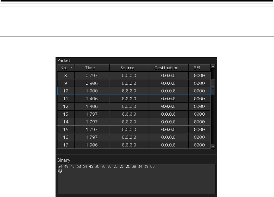
List of packets received (in
time series)
Selection Main/Sub network
Packet data
The data of the packet
selected in the packet list is
displayed.
4-27
Memo
Data saved in a log file is limited to 5MB. When the data size has reached the limit, the save
processing is stopped automatically.
<Monitoring data display example>
3 Click on the [Stop] button to stop monitoring.
4-28
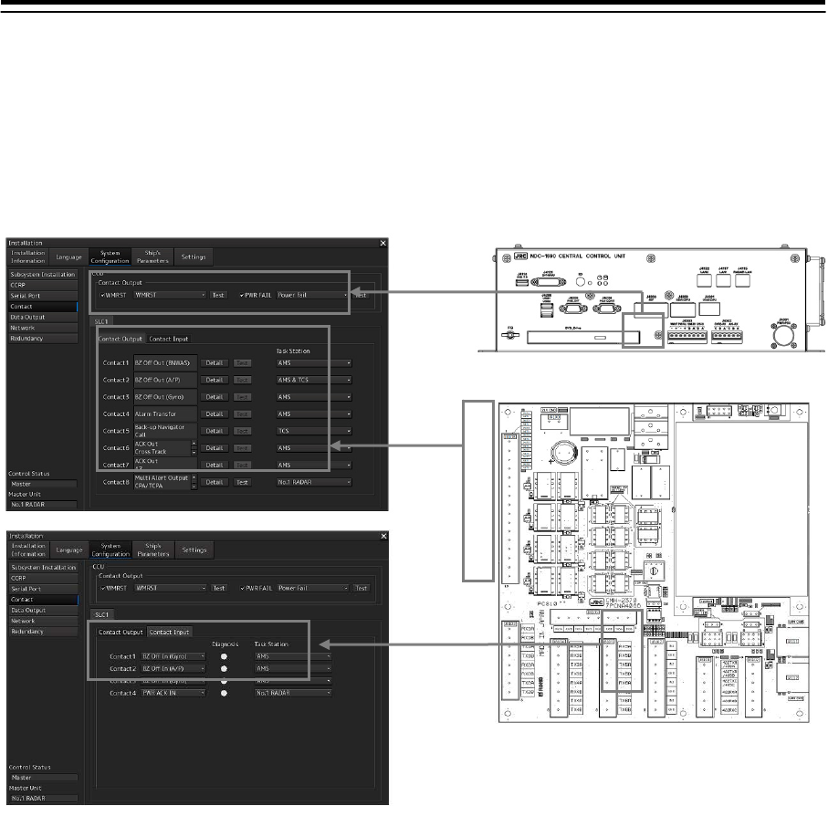
4.7 Setting Contacts
(Contact Input/Output) [ALL]
In the "Contact" dialog, functions can be assigned to the input/output of the contacts that belong to
CCU and SLC/ALC.
Displaying the "Contact" dialog
1 Display the dialog of the Installation submenu.
2 Select [System Configuration] in the 1st Classification pane and [Contact] in the 2nd
Classification pane.
The "Contact" dialog is displayed in the Edit/Result pane.
CCU contact output CCU
SLC/ALC
SLC/ALC contact input
SLC/ALC contact output
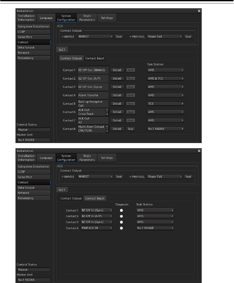
4-29
When SLC1(Main) to SLC8(Main), SLC1(Sub) to SLC8(Sub), and ALC1 to ALC8 are selected
as "installed" in the "Subsystem Installation" dialog, the functions that are currently assigned to
the contact output of Contact 1 to Contact 8 are displayed on the [Contact Output] tab. The
functions that are currently assigned to the contact input of Contact 1 to Contact 4 are
displayed on the [Contact Input] tab.

4-30
Enabling the watch timer reset contact output of the Task station
1 Select the check box of [WMRST] (watch timer reset).
2 Select the function to be assigned.
WMRST (BNWAS timer reset)
Power Fail (Alarm issued if the main AC power supply fails)
Alarm Transfer (Contact output that is output from CAM to BNWAS to transfer the alarm via
BNWAS)
Enabling the contact output for PWR FAIL of a task station
1 Select the [PWR FAIL] (power fail) check box.
2 Select the function to be assigned.
Power Fail (Alarm issued if the main AC power supply fails)
INS System Fail (the operation varies according to an assigned license.)
Operation in the system with AMS license
The message is output when the CAM in other task stations other than CAM becomes
invisible. The message is output by CAM when the ALC in which Alarm Transfer that outputs
an alert to BNWAS becomes invisible.
Operation in the system without AMS license
The alarm is output when any of the SLCs that are installed resulted in a communication
error regardless of Main/Sub of SLC.
(For details of INS System Fail, refer to "4.8 CAM Configuration and Setting.")
Back-up Navigator Call (Alarm that is output when Back-up Navigator Call occurs due to
non-acknowledgement of Cross Track/ACCA/EOT/Position Monitor/TCS Stop/ECDIS Fail
that is necessary for TCS)
Selecting the function to be assigned to each contact input of the SLC/ALC
1 Select any of the SLC1(M) to SLC8(M), SLC1(S) to SLC8(S), and ALC1 to ALC8 tabs.
2 Select the [Contact Input] tab.
3 Select the function to be assigned to each contact input from the [Contact 1] to
[Contact 4] combo boxes.
BZ Off In (BNWAS) (Buzzer Off input from BNWAS)*1
BZ Off In (A/P) (Buzzer Off input from Autopilot) *1
BZ Off In (Gyro) (Buzzer Off input from Gyro)
PWR ACK IN (PWR ACK input)
FWD/AFT Switch (FWD/AFT console switching input)
(*1) Refer to "4.8 CAM Configuration and Setting".
4 The task station used by the [Task Station] combo box is chosen to the point of
contact which assigned the function.
In the case of the item referred to at all the task stations, "All" is chosen, the task stations that
can be assigned vary depending on the function that is allocated or presence/absence of the
AMS license.
4-31
Operation in the system with AMS license
In BZ Off In(BNWAS)/BZ Off In(A/P)/BZ Off In(Gyro), the setting is fixed to “AMS”.
Operation in the system without AMS license
In BZ Off In(BNWAS), the setting is fixed to “All”.
In BZ Off In(A/P), one of the task stations, “All”, or “TCS” can be selected.
When the task station that is set is applicable to the assignment target, Active/Inactive is
displayed by the [Diagnosis] lamp for each function.
Lit in green: Active
Off: Inactive
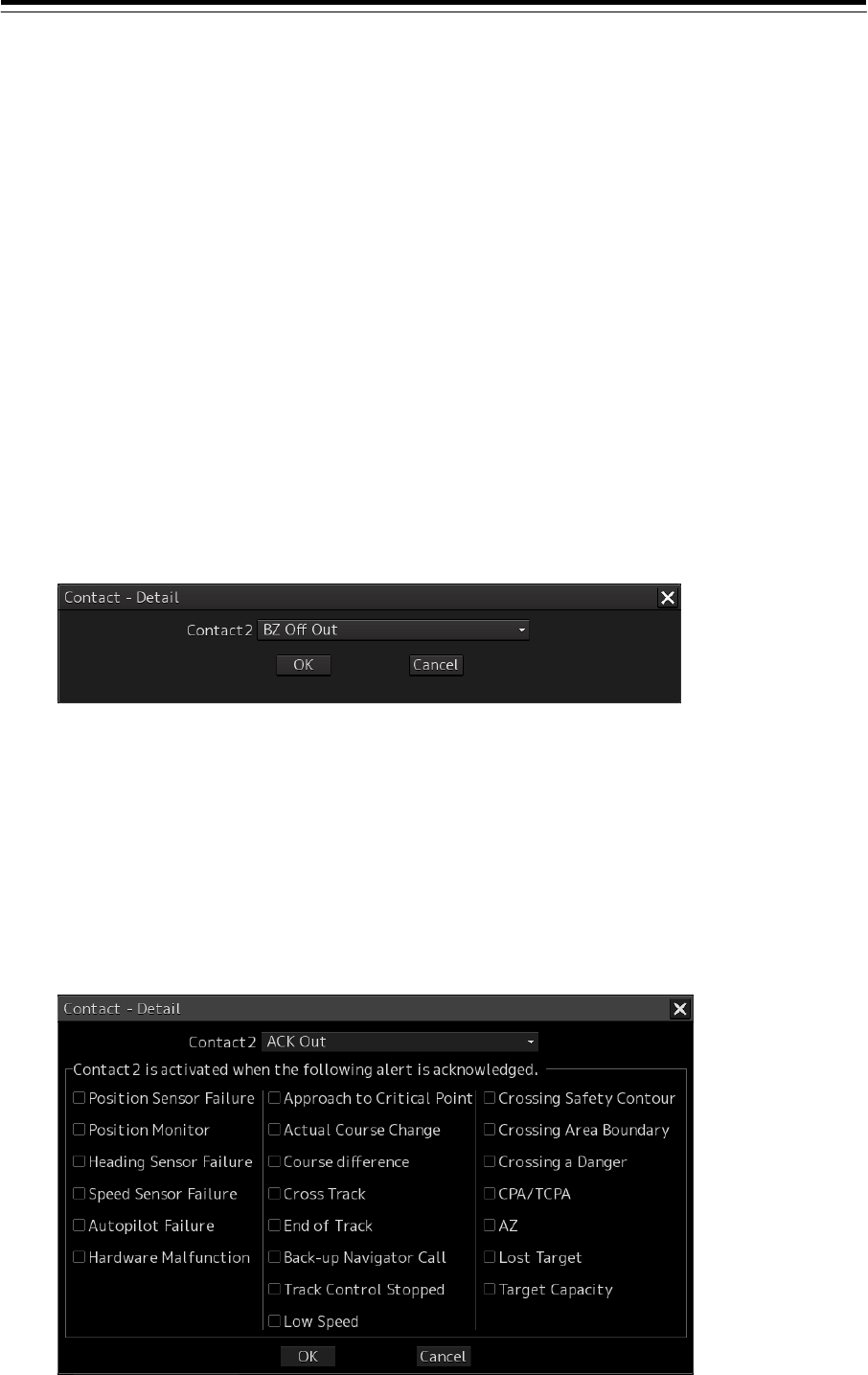
Selecting a function to be assigned to each contact output of SLC/ALC
1 Select any of the SLC1(M) to SLC8(M), SLC1(S) to SLC8(S), and ALC1 to ALC8 tabs.
2 Click on the [Detail] (detail setting) button of any of Contact 1 to Contact 8.
The "Contact-Detail" dialog is displayed.
3 Click on the function to be assigned from the combo box.
For the functions that can be assigned, refer to "Table 4-5 Contact outputs that can be
selected".
Selecting [ACK OUT]
Check boxes are displayed in the "Contact-Detail" dialog box.
Select the alert to be enabled by clicking on the check box of it. When the selected alert is
acknowledged, the contact is activated.
4-32
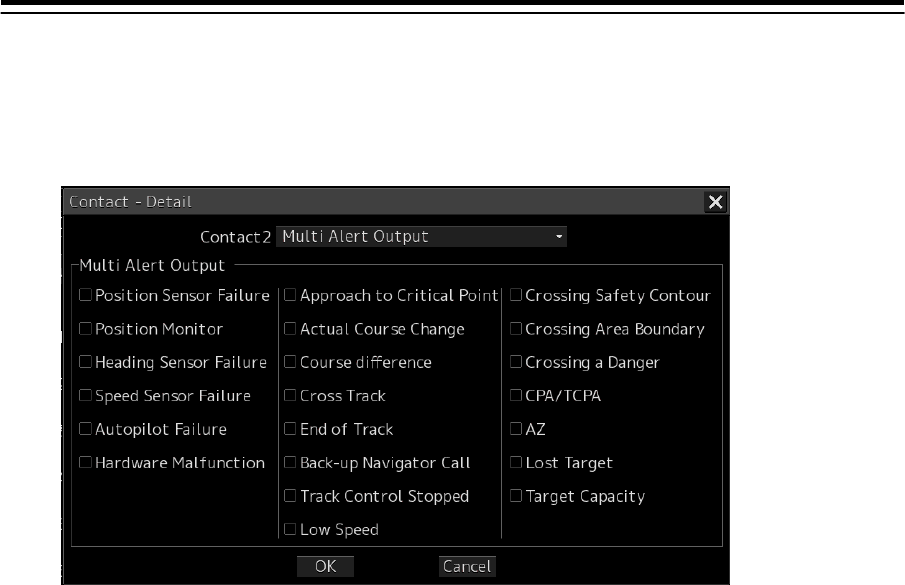
Selecting [Multi Alert Output]
Check boxes are displayed in the "Contact-Detail" dialog box.
Select the alerts to be enabled by clicking on the check box of them. When any of the checked
alert occurs, the contact is activated.
4 Click on the [OK] button.
The selected function is assigned to each contact output. To change the function to be
assigned or cancel the assignment, click on the [Cancel] button.
5 The task station used by the [Task Station] combo box is chosen to the point of
contact which assigned the function.
Operation in the system with AMS license
In ACK Out, BZ Off Out (BNWAS), BZ Off Out (Gyro), and BZ Off Out, the setting is fixed to
“AMS”.
Operation in the system without AMS license
For ACK Out, select one of the task stations in the system.
For BZ Off Out(BNWAS), select from “All” and “TCS”.
For BZ off Out(Gyro), select one of the task stations in the system or “All”.
For BZ Off Out, only “All” can be selected.
Common to each license
For Timer Reset, “All” can be selected.
For BZ Off Out(A/P), the setting is fixed to “AMS & TCS”.
For Alarm Transfer, the setting is fixed to “AMS”.
For INS System Fail, the setting is fixed to “All”.
For CPA/TCPA, AZ, Lost Target, and Target Capacity, select only one task station in the
system.

4-33
Table 4-5 Contact output that can be selected
Contact output that can
be selected Description
ACK Out ACK output (contact output to be output when all of the enabled alerts are
approved)
BZ Off Out (BNWAS)*2 Buzzer OFF output for BNWAS (the operation varies according to the license as
indicated below.)
・Operation in the system with AMS license
The contact output is output when silence operation is performed in CAM or
Emergency Call is resolved.
The contact output is output regardless of with/without alert sound.
・Operation in the system without AMS
Buzzer sound is output by silence operation on the target task station.
BZ Off Out (A/P)*2 Buzzer OFF output for Autopilot
BZ Off Out (Gyro)*2 Buzzer OFF output for Gyro Compass
BZ Off Out Buzzer OFF output (Contact output that is output when the Silence button is
pressed on BAM. The contact output can be output even without alarm
occurrence.)
Alarm Transfer BNWAS ALARM output (contact output that is output from CAM to BNWAS for
transfer of alarm via BNWAS)
INS System Fail Buzzer OFF output (Contact output that is output when the Silence button is
pressed on BAM. The contact output is output also without alarm occurrence.)
Timer Reset Timer reset notification
Position Sensor Failure Position sensor failure alarm (automatic sailing)
Position Monitor Position monitor warning (position reliability deterioration)
Heading Sensor Failure Heading sensor failure alarm (automatic sailing)
Heading Monitor *1 Heading alarm
Speed Sensor Failure Speed sensor failure alarm (automatic sailing)
Autopilot Failure Autopilot and communication failure warning (automatic sailing)
Hardware Malfunction Hardware failure alert
Software Malfunction System malfunction alarm
Approach to Critical Point Approach to critical point warning
Actual Course Change Reply notification alert
Course difference Course difference (ship’s heading departing from the course) warning
Cross of Track Cross track alarm
End of track Final destination arrival alarm
Back-up Navigator Call Backup navigator call alarm
Track Control Stopped TCS stopped
Low Speed Low speed warning
Crossing Safety Contour Crossing safety contour alarm
Crossing Area Boundary Crossing special area boundary warning
Crossing a Danger Warning for approaching to danger
CPA/TCPA CPA/TCPA alarm
AZ Automatic acquisition/automatic activation warning
Lost Target Target lost warning
Target Capacity Warning on targets reaching maximum, Warning of reaching 95% of capacity
Multi Alert Output Select when outputting multiple alerts from one contact. When this output is
selected, the Multi-Alert Output group is displayed.
(*1) Scheduled to be installed under INS support
(*2) Refer to "4.8 CAM Configuration and Setting".

4-34
Testing each contact output
1 Select one of the tabs from SLC1(M) to SLC8(M), SLC1(S) to SLC8(S), and ALC1 to
ALC8.
2 Select the [Contact Output] tab.
3 Turn on the light by clicking on the [Test] button of one of Contact1 to Contact8.
To operate the [Test] button, the task station that is output for test must have been specified in
the Task Station combo box.
4 To stop test output, turn off the light by clicking on the [Test] button again.
Checking the status of each contact input
1 Select one of the tabs from SLC1(M) to SLC8(M), SLC1(S) to SLC8(S), and ALC1 to
ALC8.
2 Select the [Contact Input] tab.
3 Confirm the display of the Diagnosis lamp.
To operate the Diagnosis lamp, the task station whose display is to be confirmed must have
been specified in the Task Station combo box.
Green lamp display: On (Active) status
White lamp display: Off (Normal) status
4-35
4.8 CAM Configuration and Setting [ALL]
This section explains alert handling settings to configure the CAM (Central Alert Management)
function. AMS license is necessary for the display to which the CAM function is to be set. For the
details, refer to “4.12 Redundancy (Setting Redundancy)”.
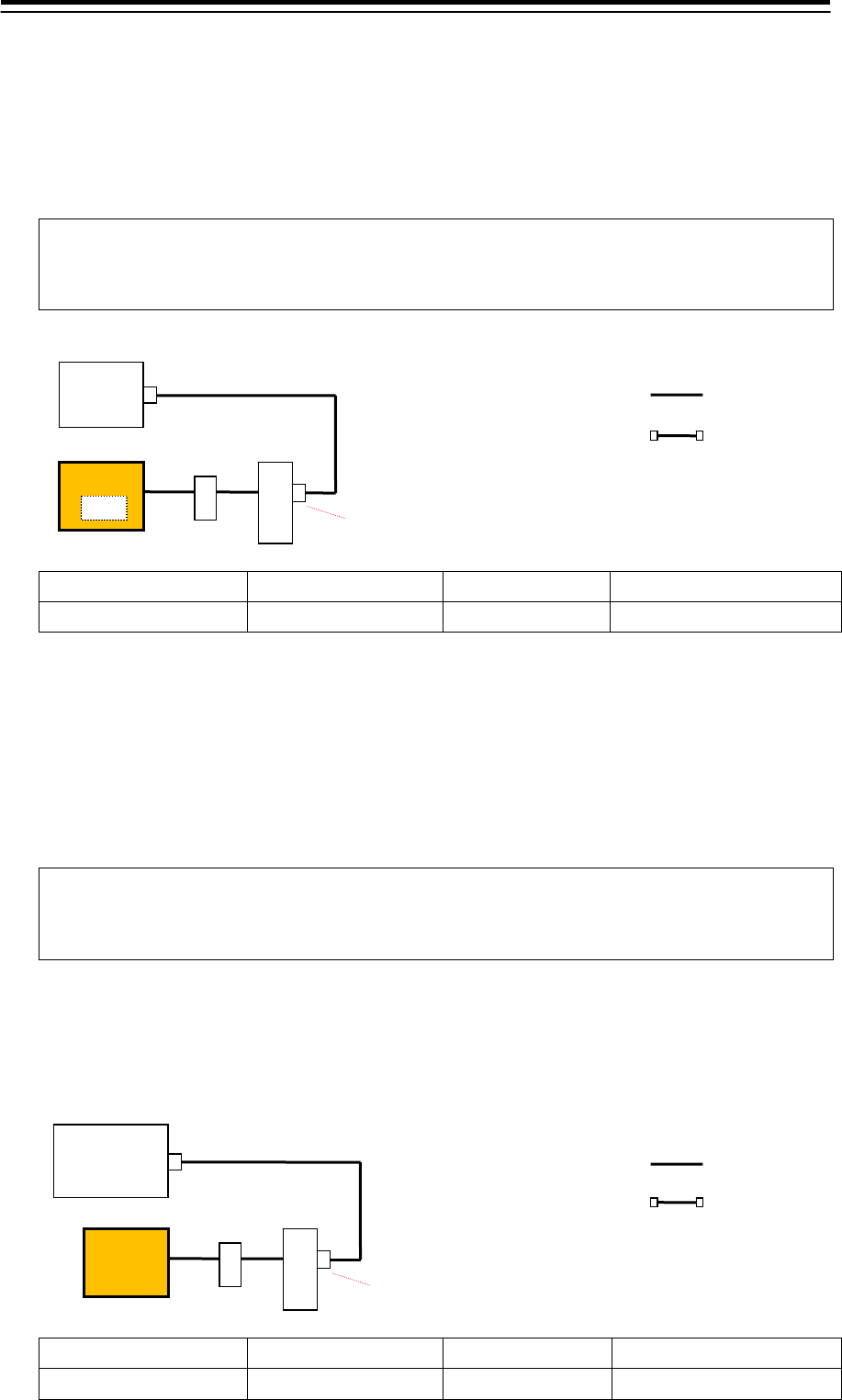
Serial port setting
Shown below are the types of serial port setting to be used for alert handling, and the details of setting.
1 Sensor data
Define the port through which data sentences are to be received from each device (sensor).
Sensor *1 Subsystem
*2 Sentence
*2 Remarks
GPS1 - -/ALR/ALF
*1 Select the sensor on the Serial Port setting screen.
*2 Sets the subsystem on the Serial Port-Detail screen.
Sensor data is received by the device that needs the data.
Sentence(ALR/ALF) is a setting value required when alerts are also received from the data port.
To receive alerts from another port, select "-" (unselected).
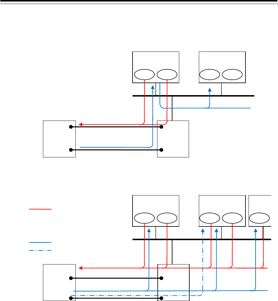
2 Alert(from Subsystem)
Define the port through which Conning(CAM) is to receive alerts from each device (e.g., sensor or
IAS).
Sensor *1 Subsystem
*2 Sentence
*2 Remarks
Alert(from Subsystem) GPS1 ALR/ALF
*1 Select the sensor on the Serial Port setting screen.
*2 Sets the subsystem on the Serial Port-Detail screen.
The port defined as "Alert(from Subsystem)" is used by Conning(CAM).
Conning S
L
C
GPS1
A
lert(from Subsystem) [GPS1]
LAN
connection
Serial
connection
HUB
CAM
RADAR S
L
C
GPS1
GPS1
LAN
connection
Serial
connection
HUB
4-36
For Subsystem, set a device connected. For Sentence, set the type of alert sentence to be
transmitted by the connected device.
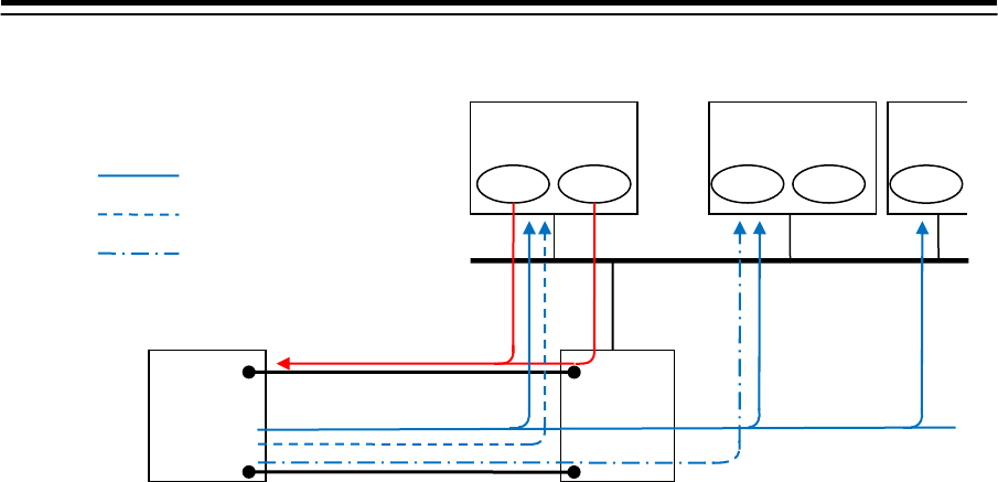
3 Alert(to BNWAS)
Define the port through which alerts are to be transmitted to BNWAS.
Memo
For the connection with BNWAS, a serial port or contact output may be used. When using
contact output, refer to "Connection with BNWAS by using contact output".
Sensor *1 Access Source
*2 Sentence
*2 Remarks
Alert(to BNWAS) AMS ALR/ALF
*1 Select the sensor on the Serial Port setting screen.
*2 Sets the subsystem on the Serial Port-Detail screen.
The port that is defined as “Alert(to BNWAS)” is used by the equipment that is selected as the
Access Source.
When AMS is selected, the port is used by CAM (main or sub).
When TCS is selected, ECDIS (main or sub) of TCS authorization is used.
Memo
When there is no CAM function in the system configuration, Set TCS. The alarm transfer
related to auto sailing is performed directly by ECIDS with TCS authorization.
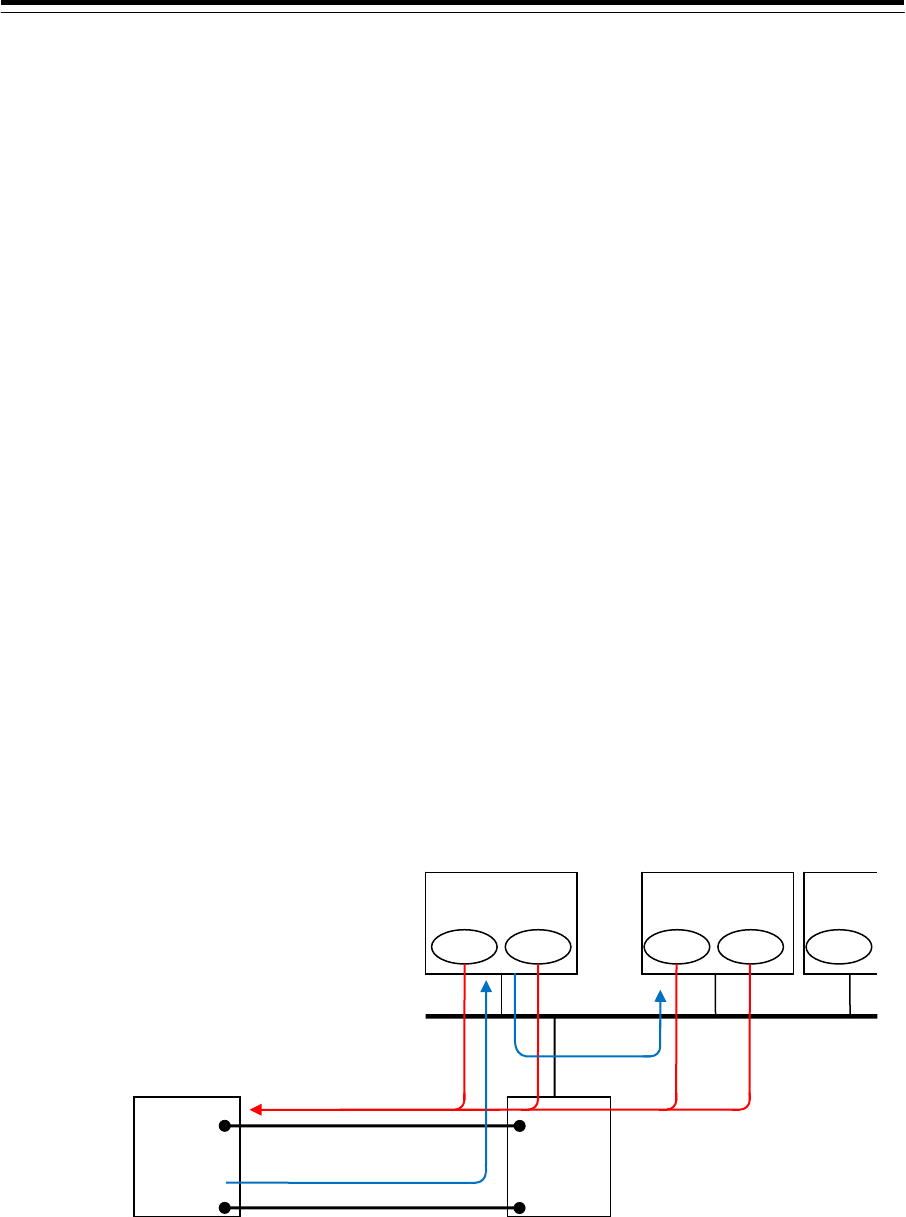
4 Alert(to CAM)
Define the port through which the task stations are to transmit alerts to CAM. This setting is
necessary if a device (e.g., competitor's product) containing the CAM function is used in place of
this equipment.
Sensor *1 Subsystem
*2 Sentence
*2 Remarks
Alert(to CAM) No.1 RADAR ALR/ALF
No.1
RADAR
S
L
C
A
lert(to CAM)
LAN
connection
Serial
connection
HUB
CAM
(Competitor's
product)
Conning
CAM
S
L
C
A
lert(to BNWAS)
LAN
connection
Serial
connection
HUB
BNWAS
4-37
*1 Select the sensor on the Serial Port setting screen.
*2 Sets the subsystem on the Serial Port-Detail screen.
The port defined as "Alert(to CAM)" is used by the device selected for Subsystem.
For Subsystem, set a device (task station) which transmits data. For Sentence, set the type of
alert sentence to be transmitted.
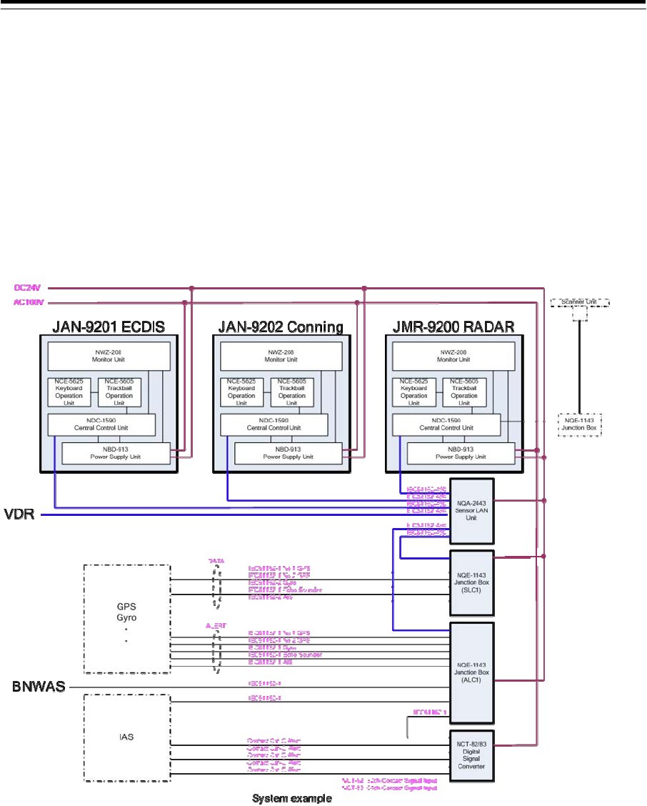
System configuration example and serial port setting example
The following shows a system configuration example, and the serial port settings required for the
system configuration.
[System configuration example]

4-38
[Serial port setting example]
Port Sensor Subsystem Sentence Access
Source Remarks
SLC1 CH1 GPS1 - - -
SLC1 CH2 GPS2 - - -
SLC1 CH3 Echo Sounder - - -
SLC1 CH4 AIS - - -
SLC1 Gyro
I/F Heading Sensor 1 - - -
ALC1 CH1 Alert(from Subsystem) GPS1 ALR -
ALC1 CH2 Alert(from Subsystem) GPS2 ALR -
ALC1 CH3 Alert(from Subsystem) Echo Sounder ALR -
ALC1 CH4 Alert(from Subsystem) AIS ALR -
ALC1 CH5 Alert(from Subsystem) Heading Sensor
1 ALR -
ALC1 CH6 Alert(to BNWAS) - - AMS
ALC1 CH7 DSC - - -
ALC1 CH9 IAS(NMEA) * - - - Primary
*IAS (NMEA) is not displayed depending on the software version.
4-39
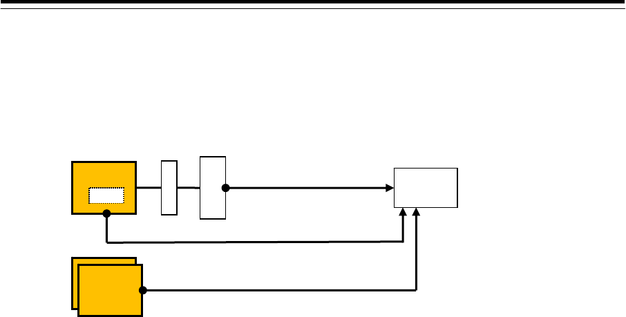
Connection with BNWAS by using contact output
See below for the connection with BNWAS when contact output is used.
[Connection example]
[1] Alarm Transfer
Set "Alarm Transfer" for the SLC/ALC contact.
In addition to the normal alarm transfer, the alarm is used for notifying that other
equipment units (ECDIS, etc.) became invisible from CAM.
[2] INS System Fail (CAM)
Set “INS System Fail” for the “PWR FAIL” contact of the task station.
Operation in the system with AMS license
The message is output by CAM when the ALC in which Alarm Transfer that outputs
an alert to BNWAS becomes invisible.
Operation in the system without AMS license
The message is output when the SLC in the system becomes invisible.
[3] INS System Fail (Each display unit other than CAM)
Set “INS System Fail” for the “PWR FAIL” contact of the task station.
Operation in the system with AMS license
The message is output when the CAM in the system becomes invisible.
Operation in the system without AMS license
The message is output when the SLC in the system becomes invisible.
BNWAS
A
L
C
Conning
CAM
Ecdis
Each
display unit
[1] Alarm Transfer
[2] INS System Fail
[3] INS System Fail
HUB
ECDIS, RADAR, - -
4-40
Connection of the contact of the buzzer Off signal
This section describes the configuration and setting for notifying buzzer Off by using contact
input/output.
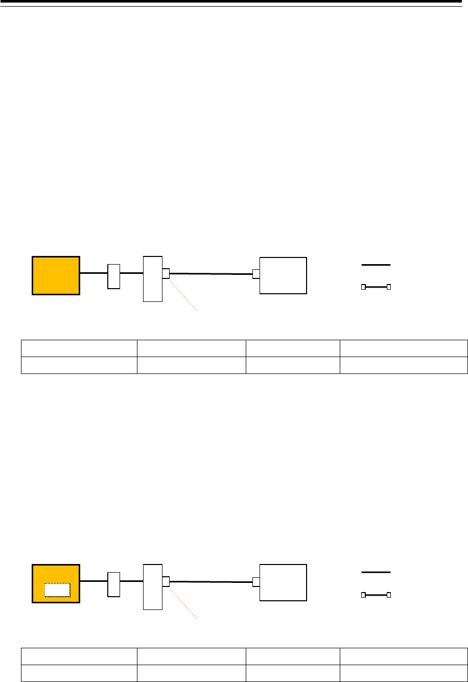
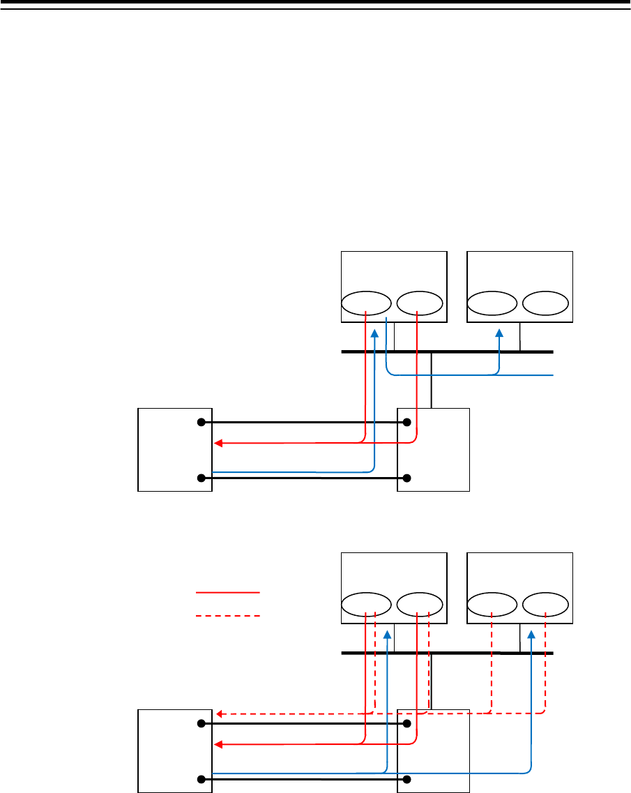
Connection with BNWAS
See below for the connection when BNWAS and CAM are connected by contacts.
[Connection in the system with AMS license]
[Connection in the system without AMS license]
[1] Contact output "BZ Off Out (BNWAS)"
Operation in the system with AMS license
Set AMS for the Task Station that is used.
When silence operation is performed on CAM, the message is output regardless of
the emission or non-emission of the alert sound.
The message is also output when Emergency Call is cancelled.
Operation in the system without AMS license
Set TCS or All in the Task Station that is used.
SLC/ALC
BNWAS
ECDIS(TCS)
[1] BZ Off Out (BNWAS)
[2] BZ Off In (BNWAS)
Silence ACK Silence ACK
RADAR
When setting TCS
When setting All
SLC/ALC
BNWAS
Conning(CAM)
[1] BZ Off Out (BNWAS)
[2] BZ Off In (BNWAS)
Silence ACK Silence ACK
ECDIS
4-41
The message is output by the silence operation on the task station that is specified
by Task Station.
Silence is not performed for the alert that occurred in a different task station.
[2] Contact input "BZ Off In (BNWAS)"
Operation in the system with AMS license
Set AMS for the Task Station that is used.
The same operation as that performed when the message is received by CAM is
performed and silence operation is performed.
All the unacknowledged alerts are silenced temporarily. Backup Navigator Call also
stops.
The Alarm Transfer contact operation is set to OFF.
Operation in the system without AMS license
Set All for the Task Station that is used.
The same operation as that performed when the message is received by all the
task stations from MBNWAS and silence operation is performed.
All the unacknowledged alerts are silenced temporarily. Backup Navigator Call also
stops.
The Alarm Transfer contact operation is set to OFF.
Connection with Autopilot
See below for the connection when buzzer off notification is performed by contact between
Autopilot and CAM.
[Connection in the system with AMS license]
SLC/ALC
Autopilot
Conning(CAM)
[1] BZ Off Out (A/P)
[2] BZ Off In (A/P)
Silence ACK
ECDIS(TCS)
Silence ACK Silence
4-42
[Connection in the system without AMS license]
[1] Contact output "BZ Off Out (A/P)"
Set the Task Station of conning (CAM) for the Task Station to be used.
Set "BZ Off Out (A/P)" for the contact output port of SLC or ALC that is connected to
Autopilot.
Buzzer Off is output when silence operation is performed or all the Autopilot alarms
are acknowledged.
[2] Contact input "BZ Off In (A/P)"
Setting in the system with AMS license
Set AMS for the Task Station that is used.
Setting in the system without AMS license
Set ALL, TCS, or task station for the Task Station that is to be used.
Set “BZ Off In (A/P)” in the contact input port of SLC or ALC that is connected to
Autopilot.
The message is notified when silence operation is performed by Autopilot regardless
of the presence or absence of the license.
SLC/ALC
Autopilot
ECDIS(TCS)
[1] BZ Off Out (A/P)
[2] BZ Off In (A/P)
Silence ACK
RADAR
Silence ACK
Selecting All
Selecting TCS
Select a task station
(Example: RADAR)
[2] Operation of BZ Off In)
の動作
Silence
4-43
Connection with Gyro Compass
See below for the connection under which buzzer off is notified by the contact between Gyro
Compass and CAM.
[Connection in the system with AMS license]
[Connection in the system without AMS license]
[1] Contact output "BZ Off Out (Gyro)"
Setting in the system with AMS license
Set AMS for the Task Station that is used.
Setting in the system without AMS license
Set All for the Task Station that is used.
Set “BZ Off Out (Gyro)” in the contact output of SLC or ALC that is connected to the
Gyro Compass.
The message is output from the task station when all the silence operation and Gyro
Compass alarms are approved regardless of the presence or absence of the AMS
license.
SLC/ALC
ECDIS(TCS)
[1] BZ Off Out (Gyro)
[2] BZ Off In (Gyro)
Silence ACK
RADAR
Silence ACK
Selecting All
Selectin a task station
(Example: RADAR)
[2] Operation of BZ Off In
Selecting All
[1] Operation of BZ Off Out
Silence
Gyro
Compass
SLC/ALC
Gyro
Compass
Conning(CAM)
[1] BZ Off Out (Gyro)
[2] BZ Off In (Gyro)
ECDIS(TCS)
Silence ACK Silence ACK

4-44
[2] Contact input “BZ Off In (Gyro)”
Setting in the system with AMS license
Set AMS for the Task Station that is used.
Setting in the system without AMS license
Set All or one of the task stations for the Task Station to be used.
Set “BZ Off In (Gyro)” in the contact input port of SLC or ALC that is connected to Gyro Compass.
The message is notified when silence operation is performed by the Gyro Compass regardless of
the presence or absence of the AMS license.
4-45
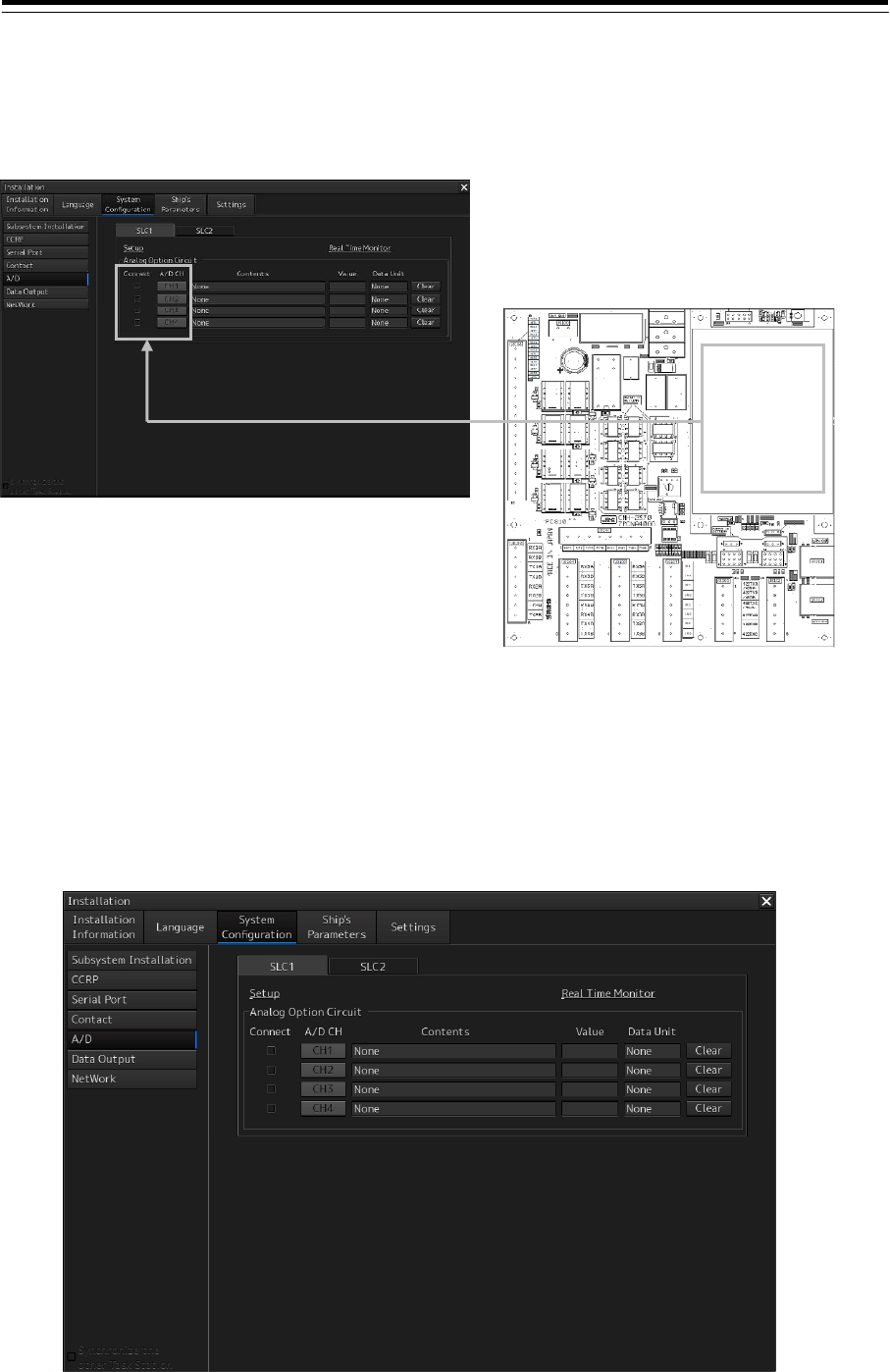
4.9 Setting A/D (Analog/Digital)
[ALL]
When making a connection to an analog sensor, settings for receiving sensor data from the analog
input on AOC can be made in the "A/D" dialog.
Displaying the "A/D" dialog
1 Display the dialog of the Installation submenu.
2 Select [System Configuration] in the 1st Classification pane and [A/D] in the 2nd
Classification pane.
The "A/D" dialog is displayed in the Edit/Result pane.
SLC
AOC
CH1 to CH4
4-46
Note
The tab display changes according to the installation position of the analog option circuit (AOC). The
"A/D" dialog is not displayed when AOC is not installed.
Selecting a channel whose connection is to be enabled
1 Select any of the SLC1(M) to SLC8(M) and SLC1(S) to SLC8(S) tabs.
2 Select the [Connect] check box.
The detail setting of each channel is displayed in the [Contents] (sentence contents) display
box, [Value] (sensor value) display box, and [Data Unit] display box.
To clear the display, click on the [Clear] button.
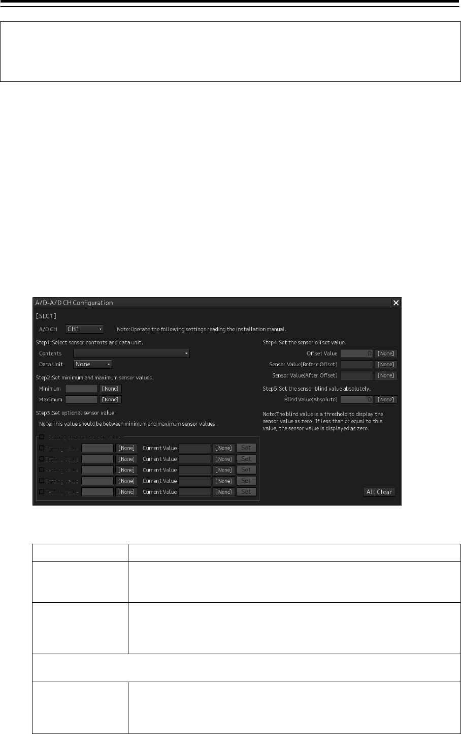
Setting channel details
1 Click on the [CH1] to [CH4] buttons.
A channel setting detail window is displayed.
2 Set the details by using the following procedure.
Setting completion condition
Step1
Selecting a sensor
type and the unit
Set [Contents] and [Data Unit]
• Select the type of the sensor to be connected to the channel that is selected in
[A/D CH] and the unit of the sensor value from the dropdown list.
Step2
Setting a range
Enter values in [Minimum] and [Maximum].
• Enter the maximum value and the minimum value of the sensor by referencing
the specification of the sensor to be connected to the channel that is selected
in [A/D CH].
A/D setting is completed when the settings up to Step 2 are made. Set Step 3, Step 4, and Step 5 as
required.
Step3
Correcting an analog
value
Check the [Setting optional sensor value] check box and enter two or more
setting values.
• For the details of settings, refer to Step 3 "Correcting an analog value: Setting
method".
4-47
Setting completion conditions
Step4
Setting offset
Enter a value in [Offset Value].
• If there is an error between the value that is displayed in [Sensor Value(Before
Offset)] and the value that is displayed in the actual sensor, enter the error
value in [Offset Value].
After the input, the value produced after offsetting to [Sensor Value(Before
Offset)] is displayed on [Sensor Value(After Offset)].
Note
When a sensor output can be adjusted freely, check the error with the sensor
output set to "0".
Step5
Setting a blind zone
Enter a value in [Blind Value(Absolute)].
• Set a blind zone within the range from +[Blind Value(Absolute)] to -[Blind
Value(Absolute)] using sensor value "0" as the center.
Example: When [Unit]-"rpm" is set and "3" is entered in [Blind Value(Absolute)],
"0 rpm" is displayed on the display unit as the range from -3 rpm to 3 rpm.
Note
• There is an input limit for the blind zone setting and the input value limit is 10%
of [Maximum].
• When using this function, set so that the sensor value "0" is included between
[Maximum]-[Minimum].
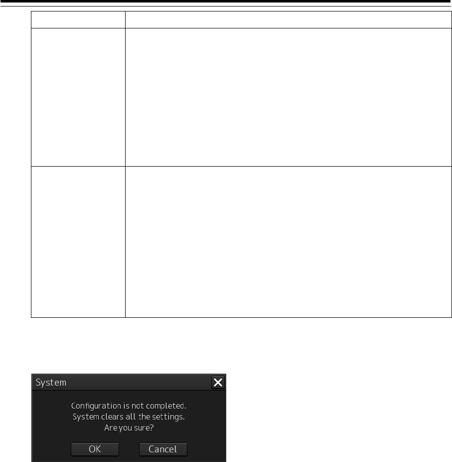
When an attempt is made to close the window by interrupting the setting, a message dialog is
displayed for termination verification.
When the [OK] button is clicked on, the values that have been changed are reset to the initial
values (values set previously). When the [Cancel] button is clicked on, the dialog is closed and
the channel setting detail window is displayed.
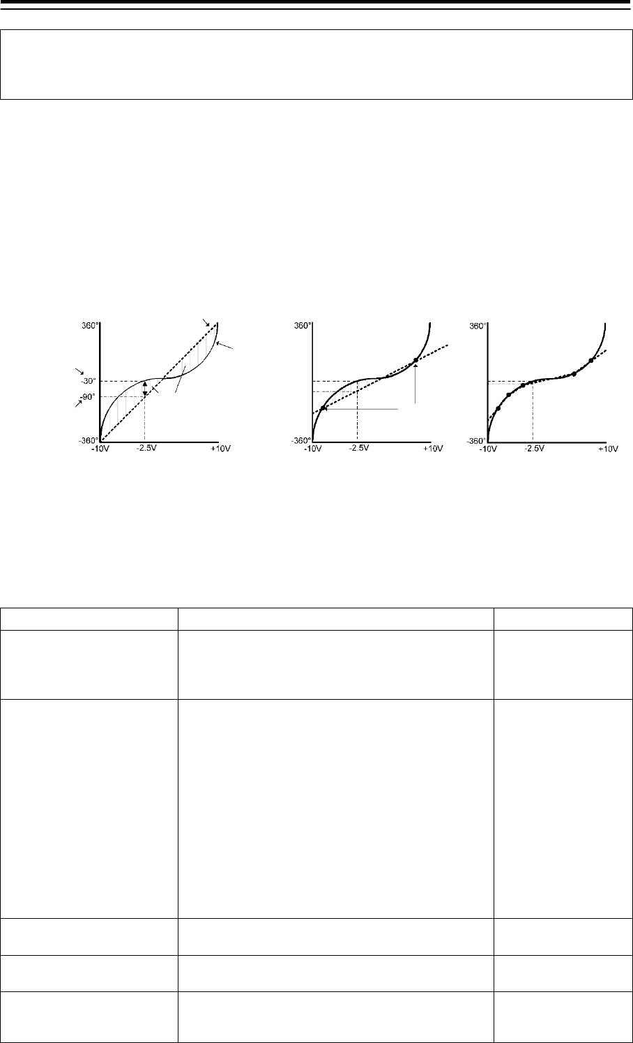
Step3 Correcting an analog value: Setting method
If there is an error between the display on the actual sensor and the display unit on the indicator,
perform correction using the following procedure.
1) Check the [Setting optional sensor value] check box.
2) Determine two value points encompassing the range to be corrected and adjust the sensor value
to either of the two.
3) Read the value of the actual sensor being connected while maintaining the output of 2) and enter
the reading in [Setting Value].
The pre-correction sensor value on the display unit is displayed in [Current Value].
4-48
Note
In [Setting Value], enter the value that is read from the meter that is attached to the sensor itself,
not the sensor value that is displayed on the display unit.
4) Press the [Set] button while maintaining the output of 2). One setting value is recorded.
5) Enter another set value in steps 2) to 4). Up to five values can be set.
As shown below, a correction is made in the form of line segment approximation of the corresponding
curve of the analog output (V or mA) and the sensor value in the section that is encompassed by the
setting values.
Example) Case where Unit: deg, Maximum: 360, and Minimum: -360 are set
• Determine the setting values so that the sensor value range that is normally used is encompassed.
• To disable the correction, uncheck the [Setting optional sensor value] check box.
The following table shows the setting contents.
Section Description of setting Setting value
[Step1]
Contents
Open the list by clicking on the button and click on
the contents of the data to be acquired with A/D.
None
Contents (Refer to
"Table 4-6 Contents
list")
[Step1]
Data Unit
Select a data unit from the combo box. 00:None
01:deg
02:min-1
03:rpm
04:m/s
05:km/h
06:knots
07:m
08:kg
09:m/min
10:N
11:%
[Step2]
Minimum
Enter the sensor minimum value in the box. Changes according to
the data unit.
[Step2]
Maximum
Enter the sensor maximum value in the box. Changes according to
the data unit.
[Step3]
Setting optional
sensor value
Enable the sensor adjustment value setting between
the minimum value and the maximum value by
selecting the check box.
Enable: Select.
Disable: Clear.
Sensor value
Before correction
AD conversion line
of the indicator
Actual sensor value
Value that is indicated
by the indicator
Error
Sensor’s output
characteristics
Sensor’s analog output value Sensor’s analog output value Sensor’s analog output value
Sensor value Sensor value
After 2-point setting After 5-point setting
Setting value

4-49
Section Description of setting Setting value
[Step3]
Setting Value
Enter a sensor value between the minimum value and
the maximum value in the box.
Changes according to
the sensor.
[Step3]
Current Value
When the [Set] button is clicked on, the current sensor
value is displayed in real time.
[Step3]
Set
Set the sensor value that is displayed in real time to
fixed display by clicking on the button.
[Step3]
Add
Add operation sentences of Setting Value, Current
Value, and Set by clicking on the button (up to 3
sentences).
[Step3]
Delete
Delete operation sentences of Setting Value, Current
Value, and Set by clicking on the button.
[Step4]
Offset Value
Enter an offset value of the sensor in the box. Changes according to
the sensor.
[Step4]
Sensor Value(Before Offset)
The sensor value prior to the reflection of the offset
value is displayed in real time.
Changes according to
the sensor.
[Step4]
Sensor Value(After Offset)
The sensor value after the reflection of the offset value
is displayed in real time.
Changes according to
the sensor.
[Step5]
Blind Value(Absolute)
Enter an absolute value of the sensor blind zone value
in the box.
Changes according to
the sensor.
All Clear Reset all the settings to the initial values by clicking on
the button

4-50
Table 4-6 Contents list
IEC61162 Display character string
Rudder order and response Rudder order, manual
Port Rudder order, manual
Starboard Rudder order, manual
Rudder response, manual
Port Rudder response, manual
Starboard Rudder response, manual
Engine order and response M/E RPM set order
M/E RPM actual response *1
Port M/E RPM set order
Port M/E RPM actual response *1
Starboard M/E RPM set order
Starboard M/E RPM actual response *1
CPP order
CPP response
Port CPP order
Port CPP response
Starboard CPP order
Starboard CPP response
Bow thruster (1 to 5) order
Bow thruster (1 to 5) response
Stern thruster (1 to 5) order
Stern thruster (1 to 5) response
Bow thruster (1 to 5) pitch order
Bow thruster (1 to 5) pitch response
Stern thruster (1 to 5) pitch order
Stern thruster (1 to 5) pitch response
*1 For CPP (variable pitch propeller), the revolution speed meter display is not available in the conning
block. Only numeric value display is available.
4-51
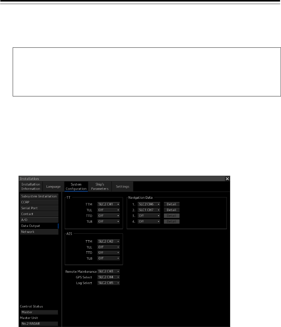
4.10 Setting Data Output [RADAR][ECDIS]
Use the "Data Output" dialog to set the channel to which data is output.
Note
Set data output so that data is not output by multiple task stations through one serial
port.
Enable the serial port for the data output on the Serial Port setting screen. (Refer to "4.6
Setting Up a Serial Port".)
Displaying the "Data Output" dialog
1 Display the dialog of the Installation submenu.
2 Select [System Configuration] in the 1st Classification pane and [Data Output] in the
2nd Classification pane.
The "Data Output" dialog is displayed in the Edit/Result pane.

4-52
Setting Data Output
Select a data output channel from the combo boxes that are listed below.
Setting item Description of setting Setting value
TTM (TT) Select a channel to which a TTM sentence of TT is output. Off
SLC1 to 8(M) CH1 to CH8/
SLC1 to 8(S) CH1 to CH8/
ALC1to 8 CH1 to CH8/
LAN
TLL (TT) Select a channel to which a TLL sentence of TT is output.
TTD (TT) Select a channel to which a TTD sentence of TT is output.
TLB (TT) Select a channel to which a TLB sentence of TT is output.
OSD(TT) Select a channel to which a OSD sentence of TT is output. SLC1 to 8(M) CH1 to CH8/
SLC1 to 8(S) CH1 to CH8/
ALC1 to 8 CH1 to CH8
RSD(TT) Select a channel to which a RSD sentence of TT is output.
TTM (AIS) Select a channel to which a TTM sentence of AIS is output.
TLL (AIS) Select a channel to which a TLL sentence of AIS is output.
TTD (AIS) Select a channel to which a TTD sentence of AIS is output.
TLB (AIS) Select a channel to which a TLB sentence of AIS is output.
Remote
Maintenance
Select a channel to which remote maintenance information
is output.
Off/
SLC1 to 8(M) CH1 to CH8/
SLC1 to 8(S) CH1 to CH8/
ALC1to 8 CH1 to CH8/
LAN(Old)/LAN(New)
LAN(Old): LAN output for
current VDR (JCY-1800)
LAN(New): LAN output for new
VDR (JCY-1900)
GPS Select Select the channel to which switching instruction is output
for GPS Selector.
*Displayed only when the Selector is "NCZ-1537A".
Off/
SLC1 to 8(M) CH1 to CH8/
SLC1 to 8(S) CH1 to CH8/
ALC1to 8 CH1 to CH8
Log Select Select the channel to which switching instruction is output
for Log Selector.
*Displayed only when the Selector is NCZ-1537A".
Navigation
Data1 to 4
Select a channel to which navigation data is output.
Select the output contents in the Detail dialog box, which is
displayed by clicking on the [Detail] button.
If "IAS" is seleced , data is output from the channel that has
been selected "IAS (NMEA)" in the Serial Port setting.
However, it is not outputted when a display unit is except
CAM(Main and Sub).
Off
SLC1 to 8(M) CH1 to CH8/
SLC1 to 8(S) CH1 to CH8/
ALC1to 8 CH1 to CH8/
IAS
4-53
Memo
- The distribution of TT and AIS can set up the combination of the following sentences.
Sentence Combination Remarks
TTM ○
TLL ○
TTD ○ ○
TLB ○ ○
* OSD and RSD sentence of TT group can be set up in all the combination.
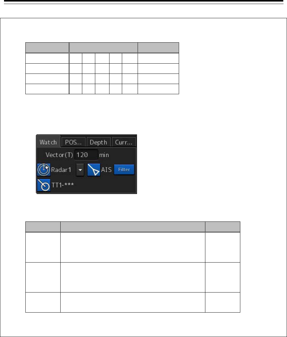
- "TT1 / 2-REL/GND/SEA" is displayed on TT display button of Sub Information Area of ECDIS by
the movement mode and stabilization mode of RADAR.
In order to be displayed correctly, set up the sentence which transmits according to the following
tables.
Sentence Description Remarks
TTM An OSD sentence is transmitted with a TTM
sentence. "TT1-***" is displayed when an OSD
sentence is not transmitted.
TLL In the case of a TLL sentence, "REL/GND/SEA"
cannot be displayed. "TT1-***" is always
displayed.
TTD "TT1-REL/GND/SEA" is displayed without
transmission of other sentences.
- “OSD” and “RSD” sentence are only transmitted by RADAR mode .
4-54
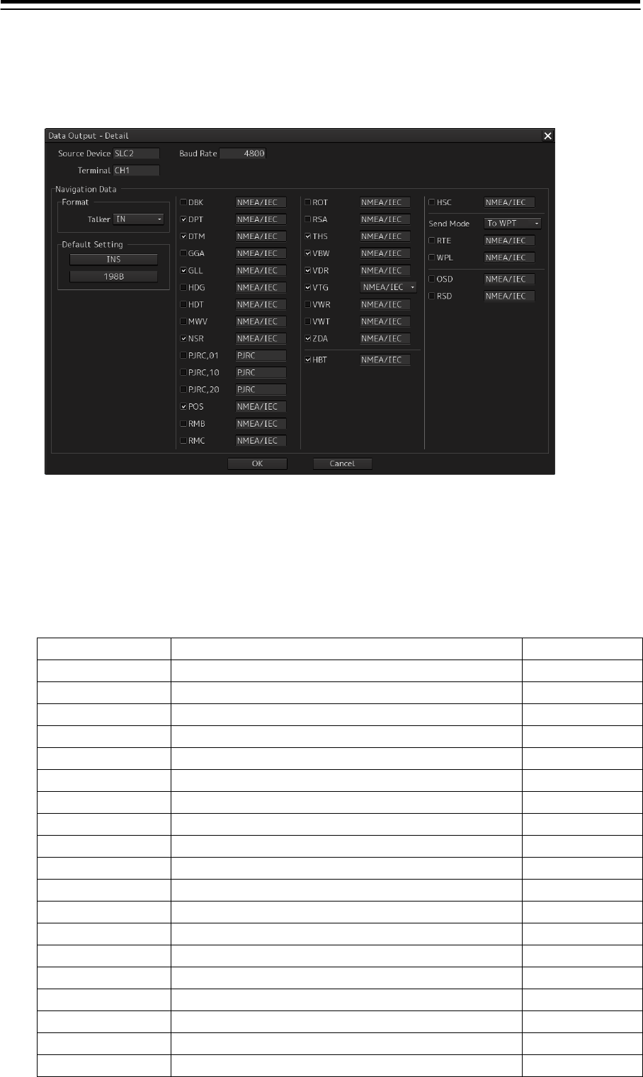
Setting the output items of [Navigation Data]
1 Click on the [Detail] button to display the Detail dialog box.
2 Select the sentence to be output.
The default settings can be selected all together by the [INS] and [198B] buttons.
INS: Selects the default items for INS.
198B: Selects the default items for 198B.
Select the sentence to be output.
Setting Item Description of Setting Remarks
DBK Selecting the check box, outputs the DBK sentence. 198B
DPT Selecting the check box, outputs the DPT sentence. INS
DTM Selecting the check box, outputs the DTM sentence. INS
GGA Selecting the check box, outputs the GGA sentence.
GLL Selecting the check box, outputs the GLL sentence. INS
HDG Selecting the check box, outputs the HDG sentence.
HDT Selecting the check box, outputs the HDT sentence. 198B
MWV Selecting the check box, outputs the MWV sentence.
NSR Selecting the check box, outputs the NSR sentence. INS
PJRC,01 Selecting the check box, outputs the PJRC,01 sentence. 198B
PJRC,10 Selecting the check box, outputs the PJRC,10 sentence. 198B
PJRC,20 Selecting the check box, outputs the PJRC,20 sentence. 198B
POS Selecting the check box, outputs the POS sentence. INS
RMB Selecting the check box, outputs the RMB sentence.
RMC Selecting the check box, outputs the RMC sentence.
ROT Selecting the check box, outputs the ROT sentence. 198B
RSA Selecting the check box, outputs the RSA sentence. 198B
THS Selecting the check box, outputs the THS sentence. INS
VBW Selecting the check box, outputs the VBW sentence. INS

4-55
Setting Item Description of Setting Remarks
VDR Selecting the check box, outputs the VDR sentence. INS
VTG Selecting the check box, outputs the VTG sentence. INS,198B
VWR Selecting the check box, outputs the VWR sentence. 198B
VWT Selecting the check box, outputs the VWT sentence. 198B
ZDA Selecting the check box, outputs the ZDA sentence. INS
HBT Selecting the check box, outputs the HBT sentence. INS
HSC Selecting the check box, outputs the HSC sentence. 198B
RTE Selecting the check box, outputs the RTE sentence.
The following information is output depending on the
contents that are selected in the Send Mode combo
box.
To WPT: Information relating to the current WPT is
output.
All: Information relating to the entire WPT is
output.
WPL Selecting the check box, outputs the WPL sentence.
The following information is output depending on the
contents that are selected in the Send Mode combo
box.
To WPT: Information relating to the current WPT is
output.
Al: Information relating to the entire WPT is
output.
OSD Selecting the check box, outputs the OSD sentence.
RSD Selecting the check box, outputs the RSD sentence.
3 Click on the [OK] button.
Note
The number of sentences that can be transmitted per second varies depending on the baud rate of
the selected channel. When a large number of sentences are selected, transmit them by adjusting
the transmission interval.
When the number of sentences that are selected exceeds the limit allowed for the corresponding
baud rate that is indicated in the following table and the OK button is pressed, a warning message
is displayed. When a warning message is displayed, increase the baud rate if possible or transmit
through multiple ports.
Baud Rate No. of sentences Remarks
2400 3
4800 5
9600 10
19200 20
38400 40
4-56
4.11 Network Setting
[ALL]
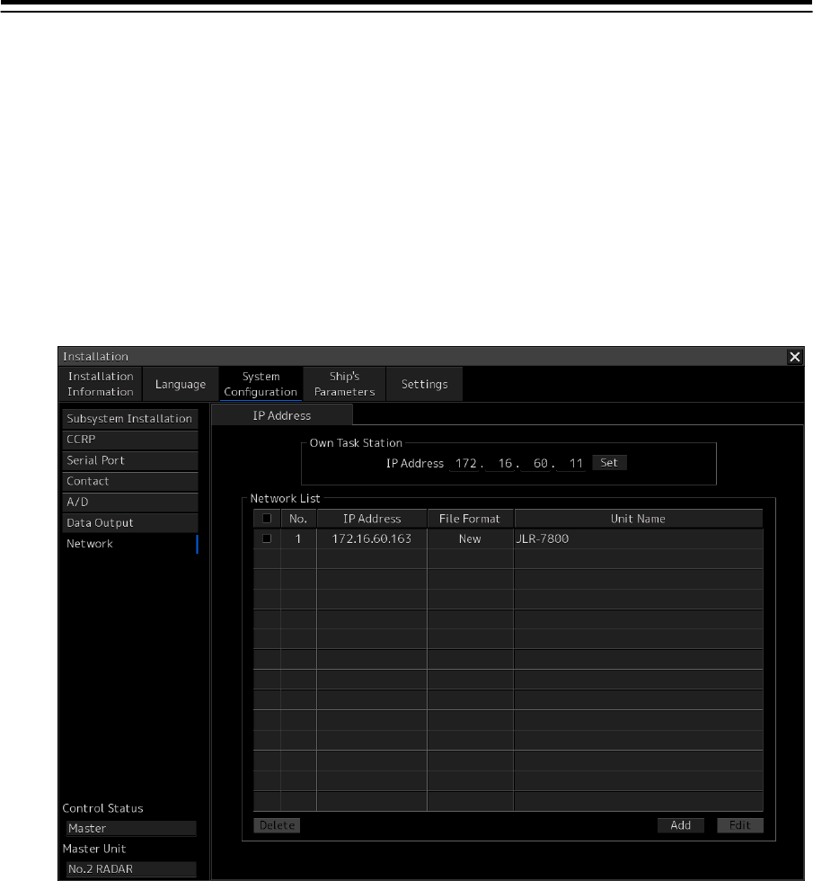
Use the "Network" dialog to set an IP address.
Displaying the "Network" dialog
1 Display the dialog of the Installation submenu.
2 Select [System Configuration] in the 1st Classification pane and [Network] in the 2nd
Classification pane.
The "Network" dialog is displayed in the Edit/Result pane.
The IP address of this equipment (Own Task Station) and the IP address of each unit on the
network are listed in [Network List].
4-57
Setting an IP address
1 Display the [IP Address] tab by clicking on the tab name display.
2 Click on the [IP Address] input box.
A numeric input keyboard is displayed.
3 Enter an IP address (from 0.0.0.0 to 255.255.255.255)
4 Click on the [Set] button.
If the set IP address is not registered in the [Network List], the address will be newly registered
as follows:
No.: Automatically assigned
File Format: New
Unit Name: Name of this unit (example: No.1 RADAR)
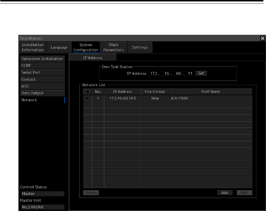
Changing the IP address of each unit on the network
1 On [Network List], check the checkbox of the row where the unit whose IP address is
to be changed is displayed.
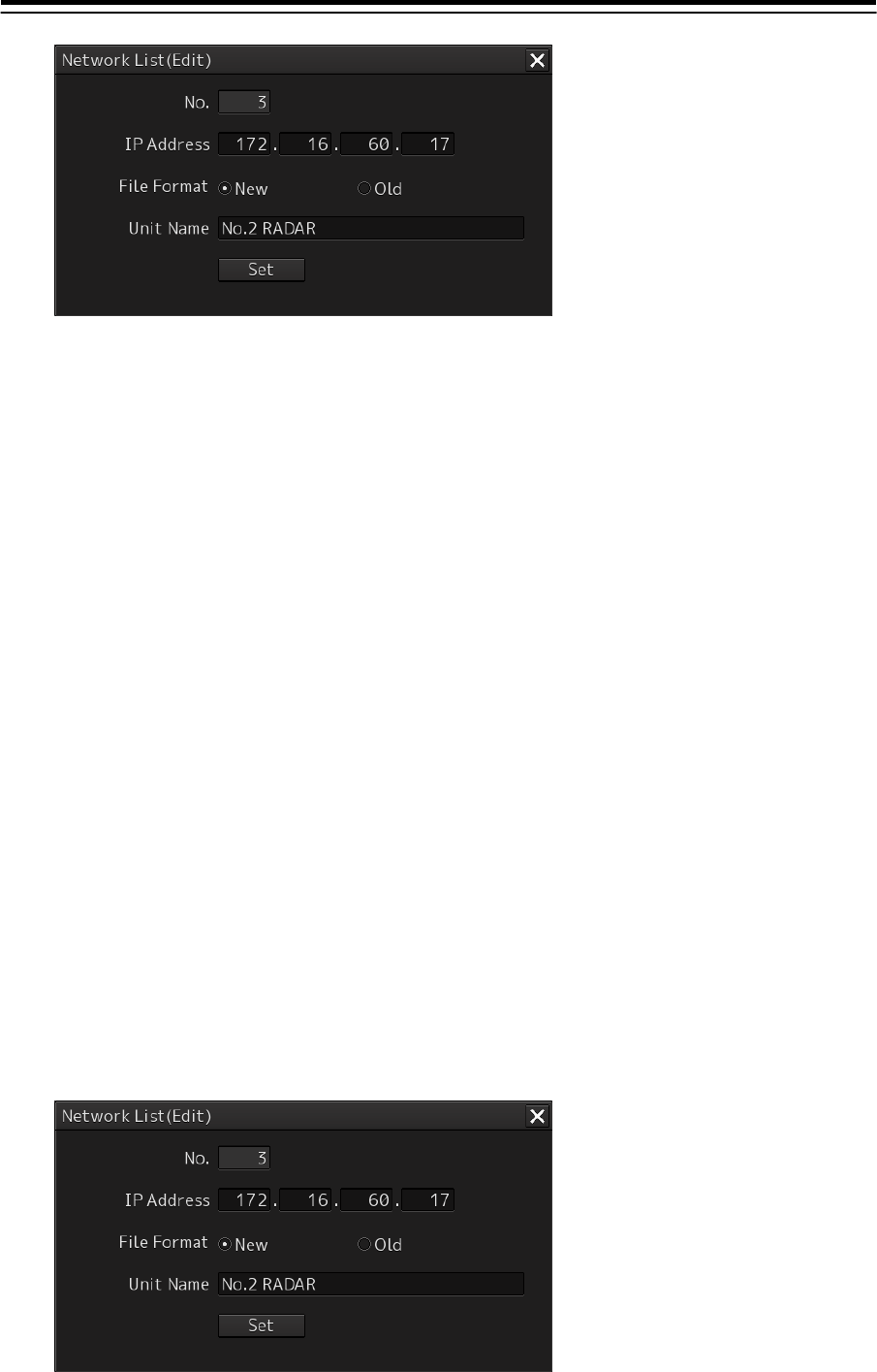
2 Click on the [Edit] button.
The "Network List (Edit)" dialog is displayed.
4-58
3 Click on the [IP Address] input box.
A numeric input keyboard is displayed.
4 Enter an IP address (0.0.0.0 to 255.255.255.255).
5 Click on the [Set] button.
The "Network List (Edit)" dialog is closed and the IP address of the unit that has been
selected on [Network List] is changed.
Editing [Network List]
Up to 32 unit information items on the network can be registered in [Network List].
The following information is registered.
No.: Automatically assigned. (1 to 32)
File Format: File format of the file sharing unit (New/Old)
New: Select "New" for this unit.
Old: Data format for old units. Select "Old" for any units other this unit.
Unit Name: Unit name (Example: No.1 RADAR)
Changing the registered information
1 On [Network List], check the checkbox of the row where the unit whose information is
to be changed is displayed.
2 Click on the [Edit] button.
The "Network List (Edit)" dialog is displayed.
3 To change the [File Format], click on the [New] or [Old] button.
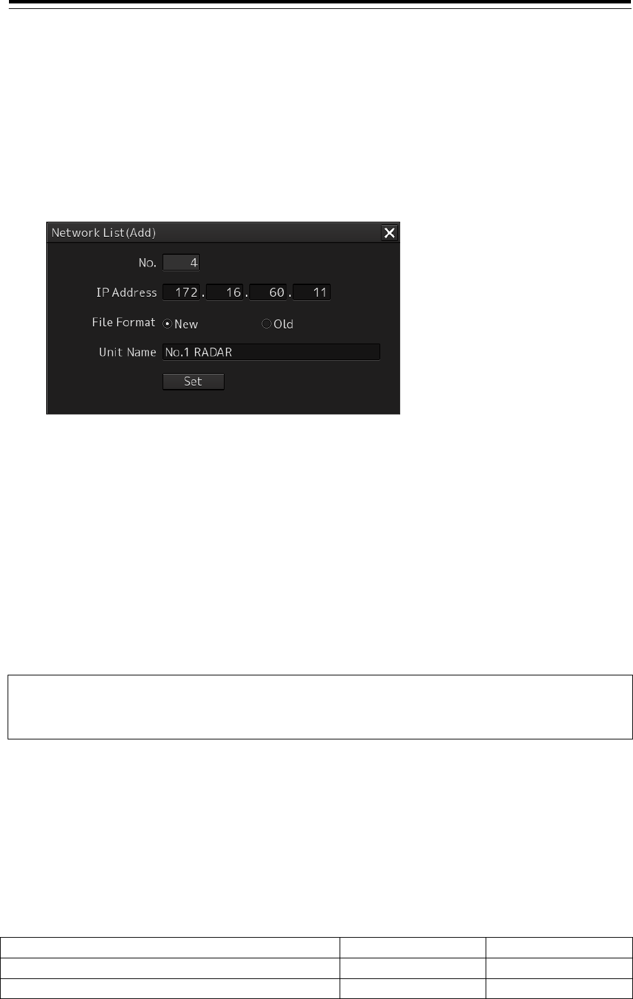
4-59
4 To change the [Unit Name], change the unit name of the input box (up to 64 characters
can be used).
5 Click on the [Set] button.
The "Network List (Edit)" dialog is closed and the information of the unit that has been
selected in [Network List] is changed.
Registering new information
1 Click on the [Add] button.
The "Network List (New)" dialog is displayed.
2 Click on the [IP Address] input box.
A numeric input keyboard is displayed.
3 Enter an IP address (0.0.0.0 to 255.255.255.255).
4 Select a file format by clicking on the [New] or [Old] button of [File Format].
5 Enter a unit name in the [Unit Name] input box (up to 20 characters can be used).
6 Click on the [Set] button.
The "Network List (New)" dialog is closed and the information that has been set in [Network
List] is displayed.
Note
Registration invalidity is displayed if at least one of [IP Address], [File Format], and [Unit Name] is
not input.
Deleting information
1 On [Network List], check the checkbox of the row where the information to be deleted
is displayed.
2 Click on the [Delete] button.
The information that has been selected in Step 1 is deleted from [Network List].
JRC Network IP Address
Network Main-LAN Sub-LAN
Old unit (used by JMA-9100 and JAN-901B) 192.168.060.xxx 192.168.061.xxx
This unit (complies with IEC61162-450) 172.016.060.xxx 172.017.060.xxx

4-60
Note
When the course is shared with GPS, set the IP address of the GPS equipment to the network IP
address 172.16.60.xxx of this equipment (complies with IEC61162-450). (For the setting method,
refer to 6.8.1.)
JRC unit IP address 4th Octet
VDR 3
4
5
6
7
8
9
10
No.1 RADAR 11
No.2 RADAR 17
No.3 RADAR 23
No.4 RADAR 29
No.5 RADAR 35
No.6 RADAR 41
No.7 RADAR 47
No.8 RADAR 53
No.1 ECDIS 59
No.2 ECDIS 65
No.3 ECDIS 71
No.4 ECDIS 77
SLC SW0 107
SLC SW1 108
SLC SW2 109
SLC SW3 110
SLC SW4 111
SLC SW5 112
SLC SW6 113
SLC SW7 114
SLC SW8 115
SLC SW9 116
SLC SW10 117
SLC SW11 118
ALC SW12 119
ALC SW13 120
ALC SW14 121
ALC SW15 122
No.1 CON 131
No.2 CON 135
No.1 CON(Wing) 139
No.2 CON(Wing) 140
No.1 CON(Remote) 141
No.2 CON(Remote) 142
No.1 RPS 156
No.2 RPS 157

4-61
JRC unit IP address 4th Octet
Chart CO 159
No.1 GPS Receiver 163
No.2 GPS Receiver 164
No.3 GPS Receiver 165
No.1 GPS RemoteDisp 166
No.2 GPS RemoteDisp 167
No.3 GPS RemoteDisp 168
No.1 Printer 181
No.2 Printer 182
No.1 AIS 192
No.2 AIS 193
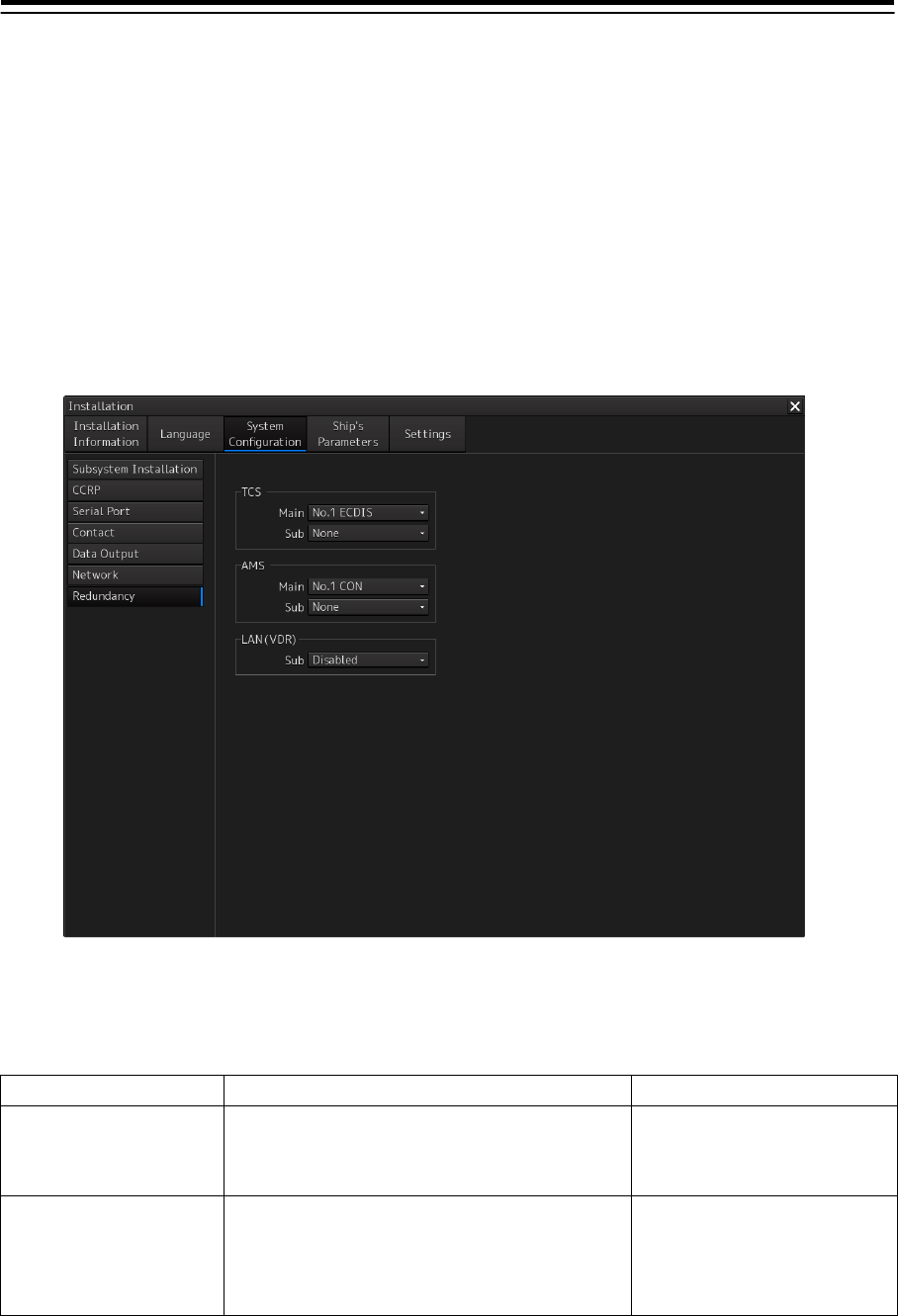
4-62
4.12 Redundancy Setting
[ALL]
Set system redundancy in the "Redundancy" dialog.
Displaying the “Redundancy” dialog
1 Display the dialog box of the Installation submenu.
2 Select [System Configuration] in the 1st classification pane and [Redundancy] in the
2nd classification pane.
The "Redundancy" dialog is displayed in the edit/result pane.
Setting ECDIS for auto sailing
Set the following items in the "TCS" group.
Setting item Description of setting Setting value
Main Select a display unit (ECDIS) for executing the
auto sailing function. A display unit (ECDIS) with
TCS license must be selected.
Display unit that is installed in
the system
*Normally, No.1ECDIS is set.
Sub Select a backup display unit of the auto sailing
function.
A display unit (ECDIS) with TCS license must be
selected.
Display unit that is installed in
the system

4-63
Setting a display unit for performing the CAM (AMS task) function
Set the following in the "AMS" group.
The display that is to be set requires the AMS license.
Setting item Description of setting Setting value
Main Select a display unit for executing the CAM
function.
Display unit that is installed in
the system
*Normally, No.1CON is set.
Sub Select a backup display unit of the CAM function. Display unit that is installed in
the system
Setting LAN single configuration/duplex configuration of VDR
Set the following in the “LAN(VDR)” group.
Setting item Description of setting Setting value
Sub Select Enable/Disable sub LAN. However, when
sub LAN is enabled, only VDR is targeted.
Enabled/Disabled
Note
“LAN” is displayed depending on the software version. Duplex configuration may not be supported.
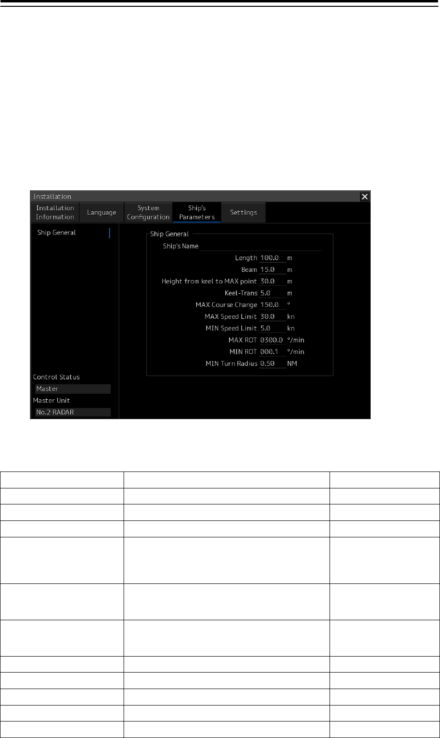
4-64
4.13 Setting Ship’s Parameters [ALL]
Use the [Ship General] dialog to set ship’s parameters.
Displaying the "Ship General" dialog.
1 Display the dialog of the Installation submenu.
2 Select [Ship Parameter] in the 1st Classification pane and [Ship General] in the 2nd
Classification pane.
The "Ship General" dialog is displayed in the Edit/Result pane.
Setting ship’s parameters
Set the following items in the "Ship General" dialog.
Setting item Description of setting Setting value
Ship's Name Enter own ship's name in the box. Max. 20 characters
Length (of ship) Enter own ship's length in the box. 1.0 to 1022.0 m
Beam (ship's width) Enter own ship's beam in the box. 1.0 to 126.0 m
Height from keel to MAX
point
(Height from the keel to the
maximum point of the ship)
Enter the height from the keel to the maximum
point of the ship in the box.
1.0 to 126.0 m
Keel-Trans
(distance between the
transducer and the keel)
Enter the distance between the transducer of the
depth sounder and the keel. (Required when
displaying the water depth with the keel fixed)
0.0 to 20.0 m
MAX Course Change
(limit value of course change
angle)
Enter the limit value of the course change angle of
the planned route in the box.
20.0 to 359.9°
MAX Speed Limit Enter the ship's maximum speed in the box. 10.0 to 99.9 kn
MIN Speed Limit Enter the ship's minimum speed in the box. 0.0 to 89.9 kn
MAX ROT Enter the maximum rate of turn in the box. 30.0 to 600.0°/min
MIN ROT Enter the minimum rate of turn in the box. 0.0 to 570.0°/min
MIN Turn Radius Enter the minimum turn radius in the box. 0.00 to 9.99 NM
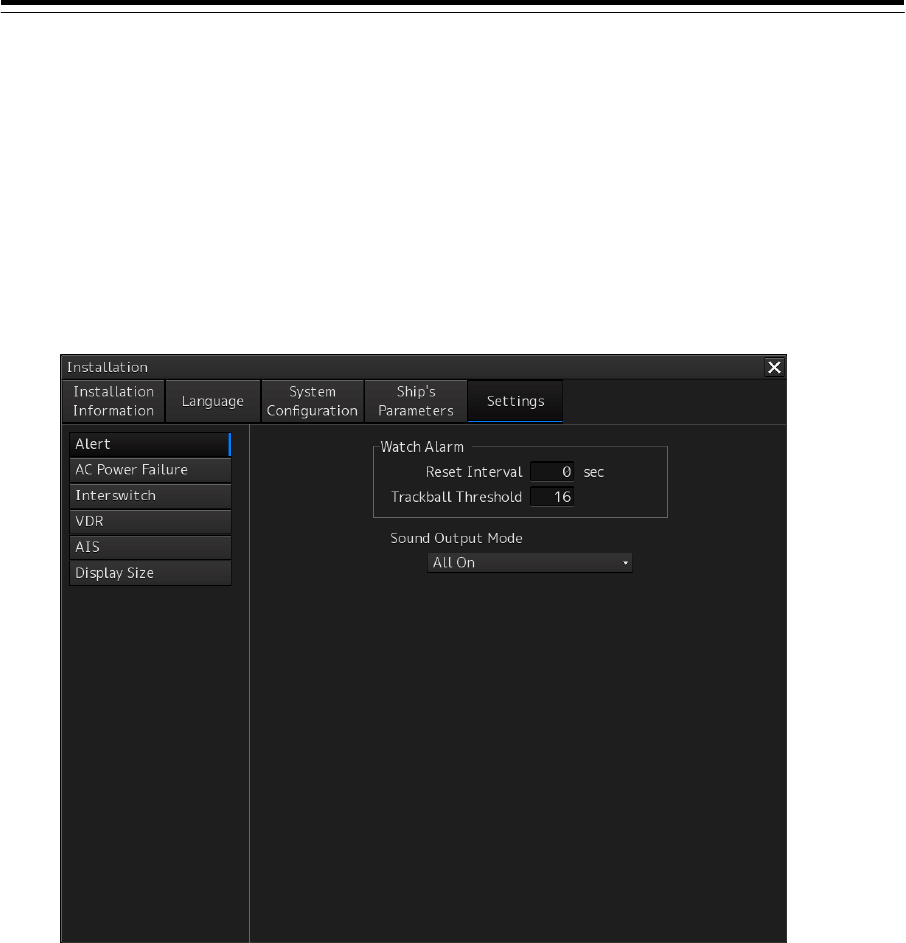
4-65
4.14 Setting Alert
[ALL]
Use the "Alert" dialog to set alert details.
Displaying the "Alert" dialog
1 Display the dialog of the Installation submenu.
2 Select [Setting] in the 1st Classification pane and [Alert] in the 2nd Classification
pane.
The "Alert" dialog is displayed in the Edit/Result pane.

4-66
Setting alert
Set the following items in the "Alert" dialog.
Setting item Description of setting Setting value
Reset Interval
Enter the interval for resetting watch alarm. When 0 is
entered, a reset signal (watch timer reset signal) is not
issued to the central monitoring unit.
0 to 999sec
Trackball Threshold Enter a trackball shift amount as the watch alarm reset
condition.
0 to 128
Sound Output Mode
Set an alert sound output mode.
All On: Emits all the alert sounds. (According to the
[Volume] setting of [General-Sounds] of the Settings
menu)
All Off: Restricts emission of all the alert sounds forcibly.
Off for Contact Output: Forcibly restricts emission of the
alert sounds that are set for contact output in [Contact
Output] of System Configuration-Contact of the
Installation submenu.
Note
The alert sounds do not include the key operation sound
(Key ACK), operation error sound (OPE Miss), and Inter
Switch setting completion sound.
All On
All Off
Off for Contact Output
Enable Power(DC Low
Voltage)
Enable Power(DC Low
Voltage) alert
Since the Power (DC Low Voltage) alert occurs in the
indicator without the DC power supply, the alert can be
suppressed.
Off: Power( DC Low Voltage) alert does not occur.
On: Power(DC Low Voltage) alert occurs.
Off/On
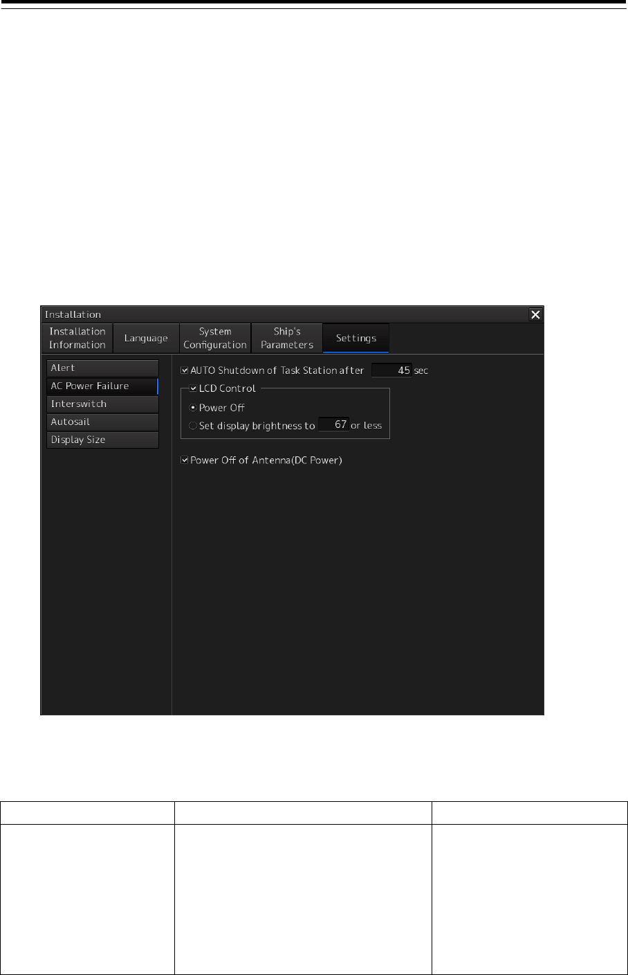
4-67
4.15 Operation Setting at AC Power Failure
(Insufficient AC power supply) [ALL]
Use the "AC Power Failure" dialog to set the operation to be performed when a "Power (AC) Voltage,
Low)" alert occurs due to insufficient AC power supply (mainly power failure).
Displaying the "AC Power Failure" dialog
1 Display the dialog of the Installation submenu.
2 Select [Settings] in the 1st Classification pane and [AC Power Failure] in the 2nd
Classification pane.
The "AC Power Failure" dialog is displayed in the Edit/Result pane.
Setting the operation to be performed at the occurrence of the "Power (AC Voltage, Low)" alert
Set the following in the "AC Power Failure" dialog.
Setting item Description of Setting Setting value
AUTO Shutdown of Task
Station
1. Use the checkbox to select whether to
shut down Task Station automatically.
2. When this item is checked, enter in the
input box the time until automatic
shutdown is executed.
Note:
When "AC Low Voltage" alert is cleared
prior to automatic shutdown, automatic
shutdown is not executed.
Shut down automatically:
Check the checkbox
Do not shut down
automatically: Uncheck
Time until automatic
shutdown:
0~9999 [sec]

4-68
Setting item Description of Setting Setting value
LCD Control 1. Use the checkbox to select whether to
control LCD.
2. When this item is checked, select the
LCD control method by clicking on the
radio button.
3. When [Set display brightness] is
selected as the LCD control method,
enter the LCD brightness value in the
[Set display brightness] input box.
Note
When "AC Low Voltage" alert is cleared
prior to automatic shutdown, the LCD is
reset to the pre-alert state.
The brightness is changed only when
the current display brightness value is
greater than the set value.
Control LCD: Check the
checkbox.
Do not control LCD: Uncheck
LCD control method
Power Off: LCD power supply is
turned off.
Set display brightness: Set the
brightness below the specified
display brightness.
LCD bright ness value:
0 to 100
Power Off of Antenna (DC
Power) (Radar antenna
power supply off (DC power
supply))
Use the checkbox to select whether to turn
off the power supply of the radar antenna
that is operating with the DC power supply.
Note
If "AC Low Voltage" alert is cleared prior to
automatic shutdown, the radar antenna
power supply is not turned off.
Turn off the power supply:
Check the checkbox.
Do not turn off the power
supply: Uncheck
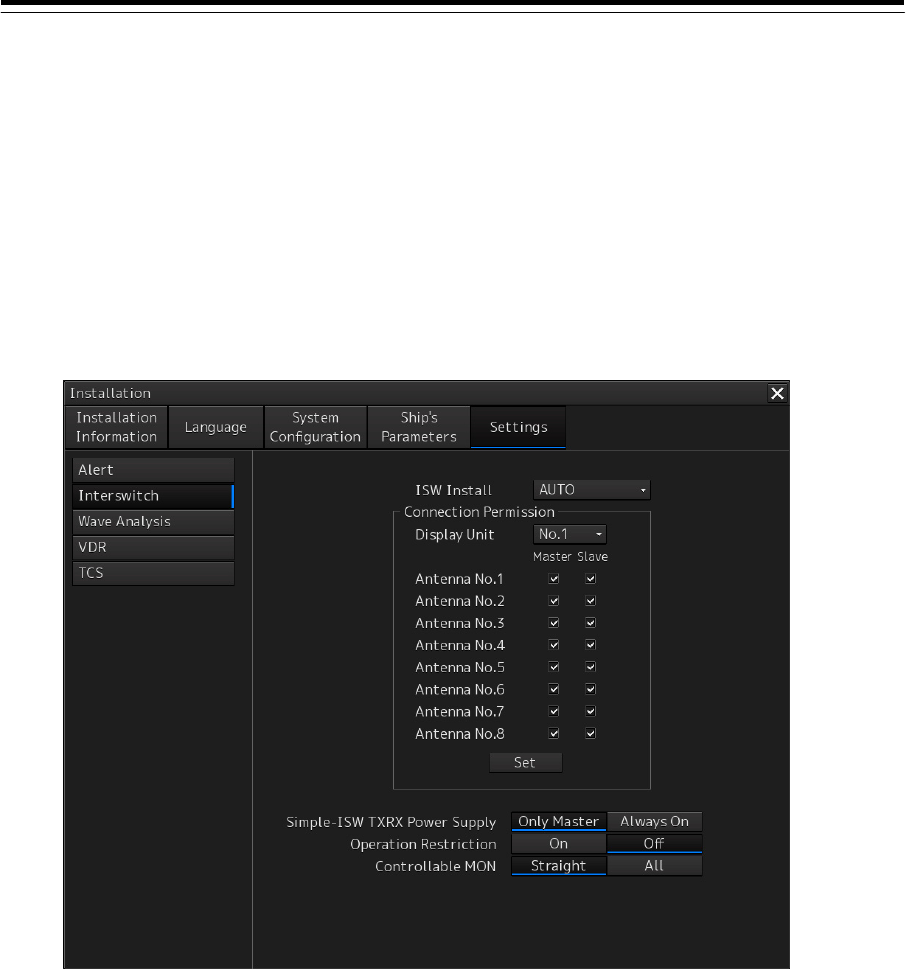
4-69
4.16 Setting Interswitch
[RADAR]
Use the "Interswitch" dialog to set the details of interswitch.
Displaying the "Interswitch" dialog
1 Display the dialog of the Installation submenu.
2 Select [Setting] in the 1st Classification pane and [Interswitch] in the 2nd
Classification pane.
The "Interswitch" dialog is displayed in the Edit/Result pane.

4-70
Setting Interswitch
Set the following items in the "Interswitch" dialog.
Setting item Description of setting Setting value
ISW Install
(Interswitch installation mode)
Select an interswitch installation mode from
the combo box.
AUTO: Checks interswitch installation
automatically.
On: Interswitch installed
Off: Interswitch not installed
Simple ISW: Simple interswitch mode
AUTO
On
Off
Simple ISW
Display Unit
(Workstation)
Select a workstation number under which
interswitch connection permission is to be set
from the combo box.
When the [Set] button is clicked on, the
interswitch setting is changed.
No.1 to No.8
Master/Slave
(Master/slave)
Select Master/Slave of the antenna that can
be connected via the interswitch from the
workstation that is selected [Display Unit] by
selecting the antenna number check box.
When the [Set] button is clicked on, the
interswitch setting is changed.
Master
Slave
Simple-ISW TXRX Power Supply
(Power supply to the antenna by
simple interswitch)
Set highlight display by clicking on the button
and select whether the power supply for own
antenna is constantly set to ON or the power
supply is set to ON only for the master
antenna when a simple interswitch is used.
Only Master (ON for
master only)
Always ON
Operation Restriction
(Operation restriction)
Set highlight display by clicking on the button
and select operation restriction On/Off.
When On is selected, the following
interswitch functions are restricted.
Change the connection statuses of other
workstations at switching of the connection
status between the antenna and the
workstation.
Load the connection patterns.
Set the name in the antenna/workstation.
On
Off
Controlable MON
(Controllable performance
monitor)
Set highlight display by clicking on the button
and set controllable performance monitor.
Straight: Can adjust only the performance
monitors of the antennas of straight
connection.
All: Can adjust performance monitors of the
antennas other than those of straight
connection also.
Straight
All
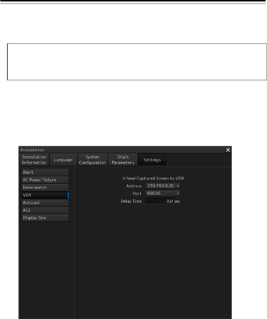
4-71
4.17 Setting VDR [RADAR][ECDIS]
User the "VDR" dialog to set the details of VDR (JRC).
Displaying the "VDR" dialog
1 Display the dialog of the Installation submenu.
2 Select [Setting] in the 1st Classification pane and [VDR] in the 2nd Classification pane.
The "VDR" dialog is displayed in the Edit/Result pane.
Note
When VDR (JRC) "installed" is not specified in the Subsystem Installation dialog, the "VDR"
dialog is not displayed.

4-72
Setting VDR
Set the following items in the "VDR" dialog.
Setting item Description of setting Setting value
Send Captured Screen to VDR Select whether images are captured at every
15 seconds and transmitted via the network
for VDR.
Transmit: Select.
Not transmit: Clear.
Address When [Send Captured Screen to VDR] is
selected, select a transmission destination
multicast address of the captured image.
239.192.0.26/
239.192.0.27/
239.192.0.28/
239.192.0.29/
239.192.0.30
Port When [Send Captured Screen to VDR] is
selected, select a transmission destination
port number of the captured image.
60026/
60027/
60028/
60029/
60030
Delay Time Enter in the input box a delay time when
transmitting an image from RADAR or
ECDIS.
Set an interval so that the output timings are
not concentrated when data is sent from
each device.
0.0 to 14.5 sec
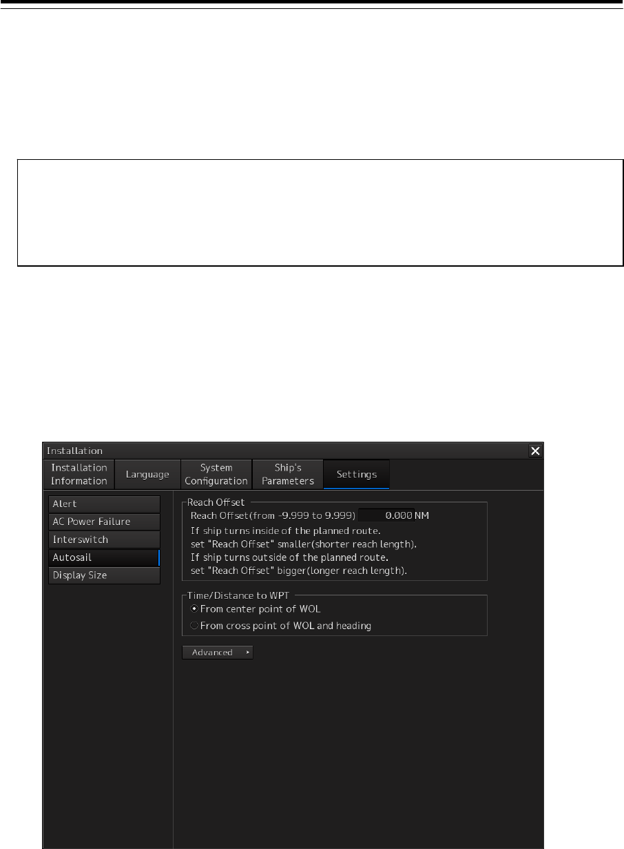
4-73
4.18 Setting Autosail (Automatic Sailing
System) [ECDIS]
By using the "TCS" dialog, verify and initialize the automatic sailing system that is installed in this
equipment.
Displaying the "Autosail" dialog
1 Display the dialog of the Installation submenu
2 When you select [Settings] in the 1st Classification pane and [Autosail] in the 2nd
Classification pane.
The "Autosail" dialog is displayed in the Edit/Result pane.
Note
Unless the following two conditions are satisfied, the "TCS" dialog is not displayed.
• "TCS function" is provided as an optional license.
• "Installed" is set for "Autopilot" in the Subsystem Installation dialog.
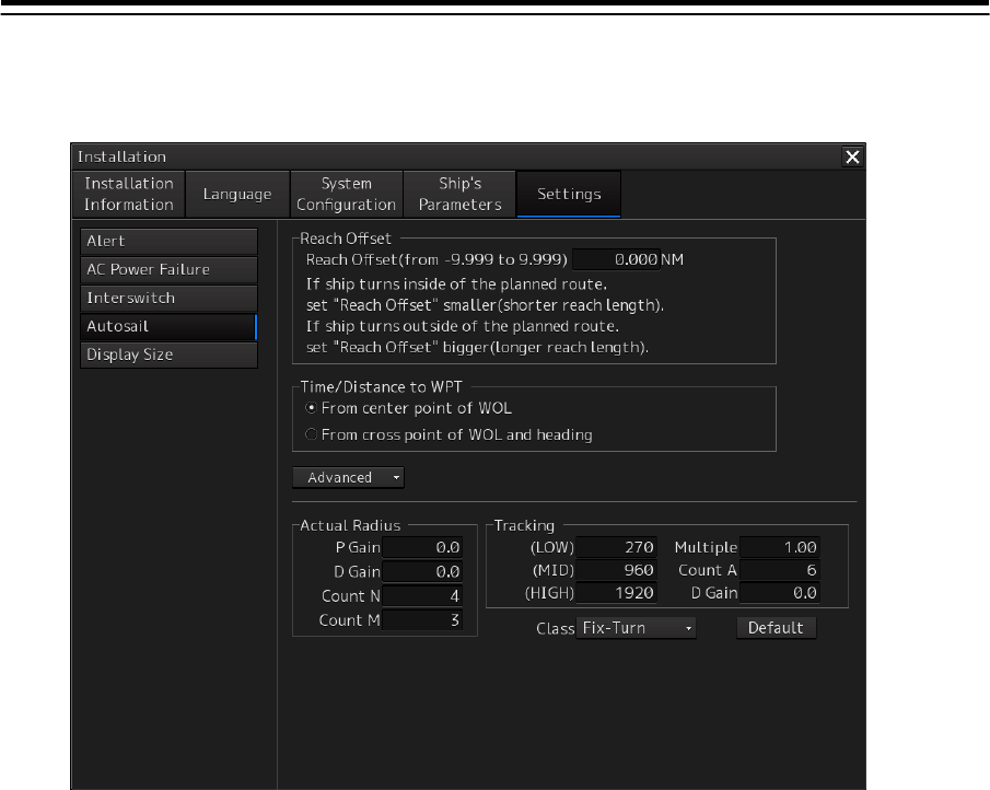
4-74
Clicking on the [Advanced] (extended display) button shows the [Actual Radius] and [Tracking]
display sections.

4-75
Setting the automatic sailing system
Set the following items in the "Autosail" dialog.
Setting Item Description of Setting Setting Value
Reach Offset Enter the reach offset in the box.
For the details, refer to "Reach Offset".
-9.999 to 9.999 NM
Time/Distance to WPT Select this to select the method of
calculating the time and distance from own
ship to WPT.
From cross point of WOL and leg:
Calculate between "own ship" and
"intersection between WOL and leg".
(Recommended)
From cross point of WOL and heading:
Calculate between "own ship" and
"intersection between WOL and ship’s
heading".
For the details, refer to "Time/Distance to
WPT".
• From cross point of WOL and
leg
• From cross point of WOL and
heading
Actual Radius (Order turn
course radius)
To calculate an order turn course radius,
enter a proportional gain (P Gain), a
differential gain (D Gain), an averaging
count for proportion (Count N), and a
difference averaging count (Count M) in the
box.
Note
Not used when Autosail Category B/C of
TOKYO KEIKI is used.
P Gain: 0.0 to 999.9
D Gain: 0.0 to 9999.9
Count N: 0 to 999
Count M: 0 to 999
Tracking To calculate a course to steer, enter a gain
(Low, MID, High), an exponential term
(Multiple), a gain averaging count (Count A),
and a derivative term gain (D gain) in the
box.
For the details, refer to "Tracking".
Note
Not used when Autosail Category B/C of
TOKYO KEIKI is used.
Low/Mid/High: 0 to 9999
[min.(1/60°)/NM]
Multiple: 0.00 to 1.00
Count A: 0 to 999
D Gain: 0.0 to 999.9
Class Select a ship model in the combo box. The
Advanced setting parameters are changed
collectively according to the selected ship
model.
Note
When Autosail Category B/C of TOKYO
KEIKI is used, no input is required.
Fix-Turn
Fast-Ferry
Container
Tanker
Default Collectively reset the Advanced setting
parameters to the setting values at factory
delivery by pressing the button.
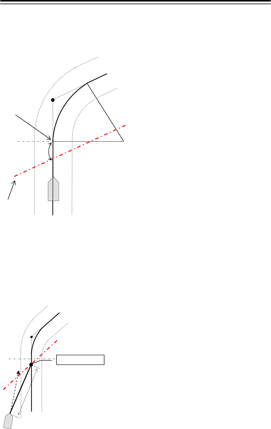
4-76
Reach Offset
When the turning angle is ±3 degrees or more, WOL is displayed at the position (Reach Offset position)
by the reach length before WOP, which is the intersection of the turning radius and leg. The reach
derivation calculation method varies depending on the auto pilot that is connected.
Time/Distance to WPT
From cross point of WOL and leg (based on the center point between own ship and WOL)
As shown below, the distance/TTG calculation reference point is used as the center point of WOL. As a
result, the distance to TO WP can be calculated almost accurately regardless of XTD of own ship and
ship’s heading. However, note that the timing does not always match the ECC/ACC display timing.
WOL
TO WP
Distance
Center of WOL
WP
Reach length
WOL
WOP
Turning radius
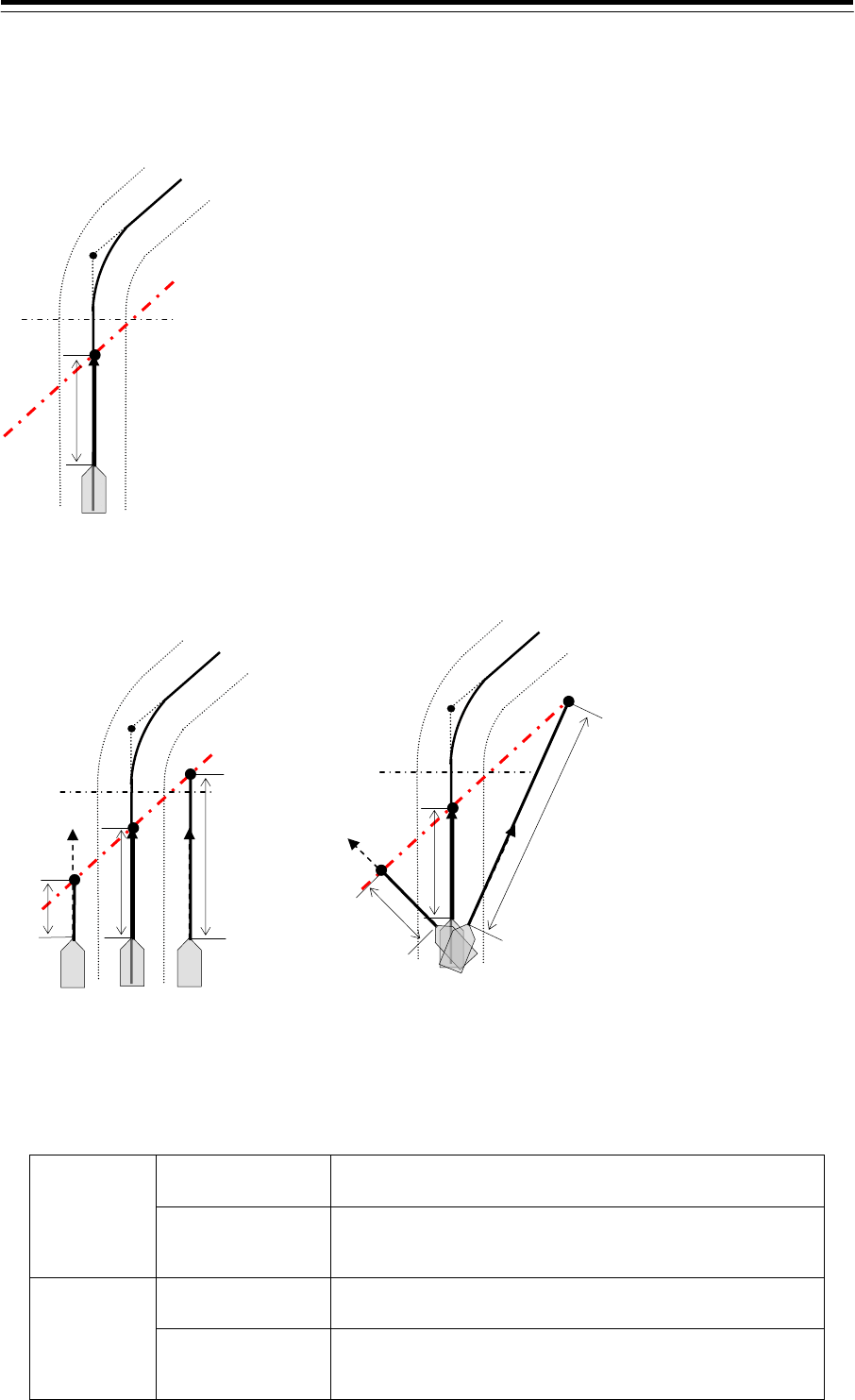
4-77
From cross point of WOL and heading (based on the intersection between ship’s heading and
WOL)
With the same calculation method as the ECC/ACC derivation timing, the TTG display timing and
ECC/ACC occurrence timing match.
However, when own ship is off-course from the center of the route or the heading of own ship
does not match the leg bearing as shown below, the value changes significantly.
Switching between From cross point of WOL and leg and From cross point of WOL and heading
Dest WP calculation switches as follows.
From cross
point of WOL
and leg
DestWP=TO WP Calculate the distance between own ship and the center of
WOL of TO WP (Figure A)
DestWP>TO WP For the subsequent leg length, add the distance between WPs
to the distance between own ship and WOL center of TO WP.
(Figure B)
From cross
point of WOL
and heading
DestWP=TO WP Calculate the distance between own ship and the intersection
of the heading of own ship and WOL of TO WP (Figure C).
DestWP>TO WP For the subsequent leg length, add the distance between WPs
to the distance between own ship and the intersection of own
ship heading and WOL of TO WP (Figure D).
WOL
TO WP
Dis-
tance
WOL
TO WP
Distance
Heading of own ship does not match the
leg bearing
Dis-
tance
Distance
Own ship is off-course
WOL
TO WP
Dis-
tance
Distance
Dis-
tance
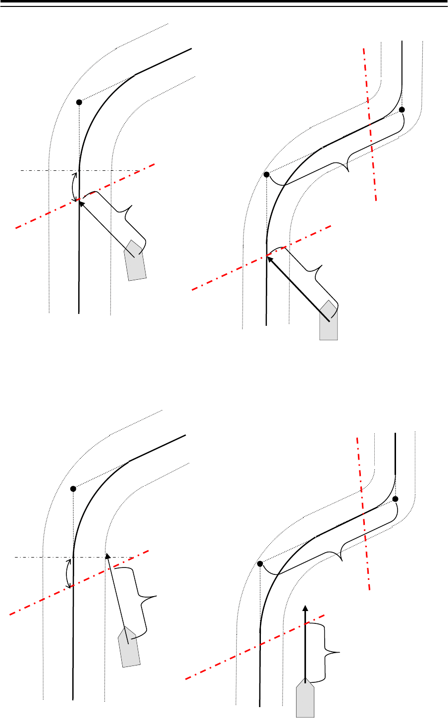
4-78
Figure B
Figure A
WP
Reach length
Distance
WP
Distance 1
WP
Distance 2
Figure C Figure D
WP
Reach length
Distance
WP
Distance 1
WP
Distance 2
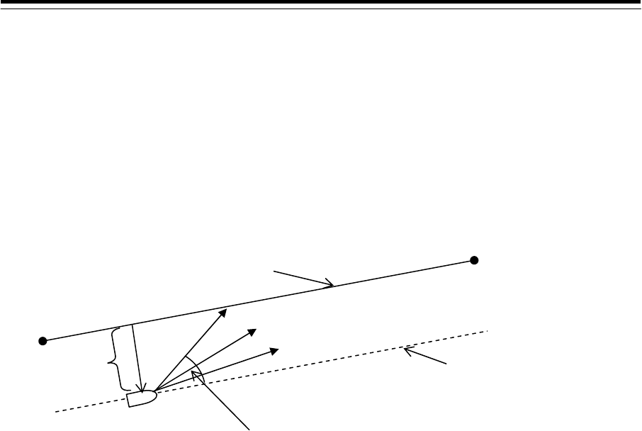
4-79
Tracking
A tracking gain is a value that indicates the degree of swiftness for returning to the course when the ship becomes
off-course. Three types of gain values are available, Low, Mid, and High.
For instance, assume that own ship’s position is set to 1NM on the right side of the leg, and the gain is set to
16deg./NM (Mid). In this case the ship approaches the leg at the angle of 16°. As the distance (LD) between the
ship and the leg decreases, the angle also decreases. While the ship is sailing on the leg, the angle is the same
angle of WP1 viewed from WP0. If the LD increases, the angle also increases. The rudder control may become
impossible depending on the setting of the gain.
Tracking gain High: 32.0 deg./NM
Mid: 16.0 deg./NM
Low: 4.5 deg./NM
Own ship
WP0
WP1
Current leg
Line parallel to the leg
Low
Mid
High
LD
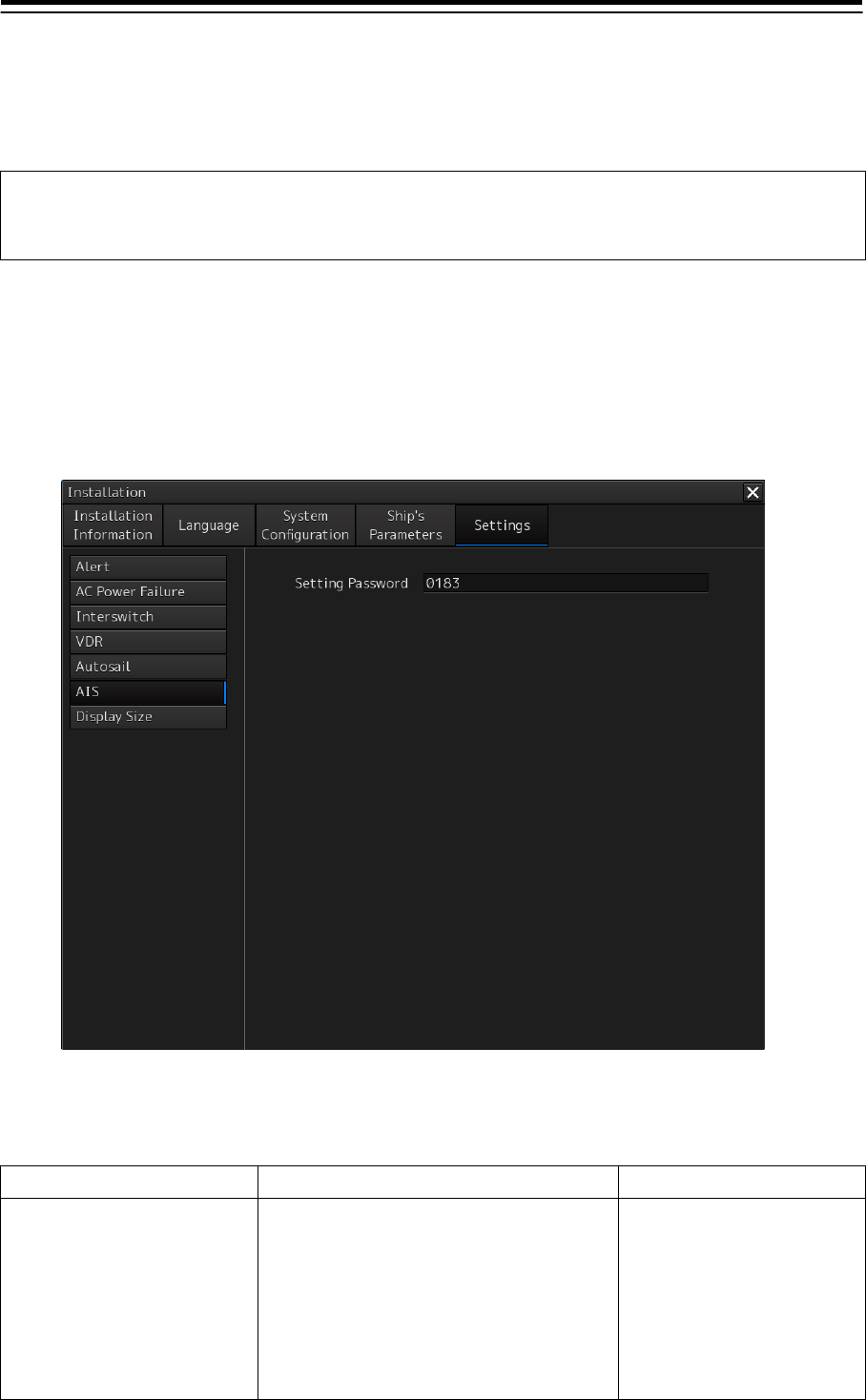
4-80
4.19 Setting AIS
[RADAR][ECDIS]
Set AIS in the "AIS" dialog.
Note
When AIS "installed" is not set in the subsystem Installation dialog, the "AIS" dialog is not
displayed.
Displaying the "AIS" dialog
1 Display the dialog of the Installation submenu.
2 Select [Setting] in the 1st Classification pane and [AIS] in the 2nd Classification pane.
The "AIS" dialog is displayed in the Edit/Result pane.
Setting AIS
Set the following in the "AIS" dialog.
Setting item Description of setting Setting value
Setting Password JHS-183 requires a password when
changing the Voyage data from an external
device.
If you have changed password on the AIS,
change this setting to the same password.
JHS-182 does not requires a password , this
setting is ignored.
Up to 32 characters (numeric
value only)
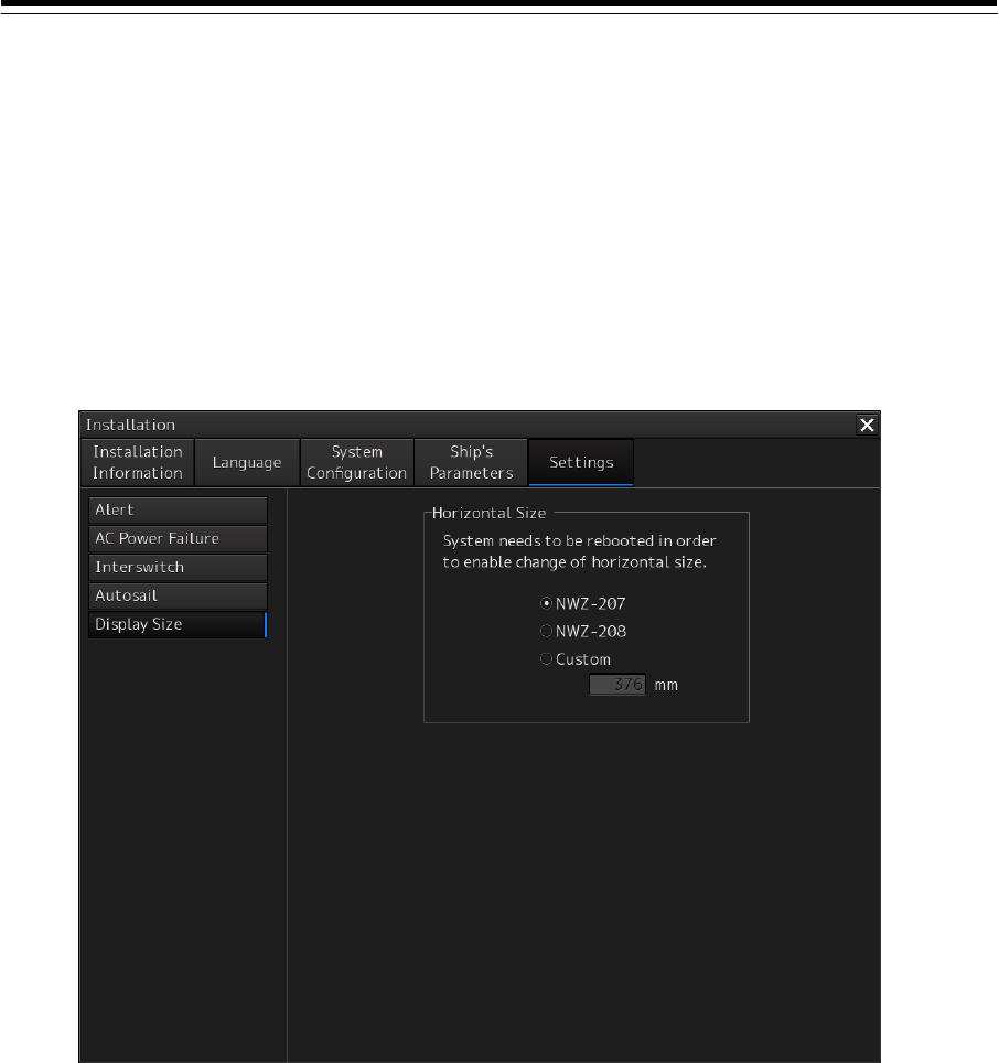
4-81
4.20 Setting Display Size [ALL]
Use the "Display Size" dialog to set the horizontal width (excluding the display frame and blank
spaces) of the display section of the display to be used.
Displaying the "Display Size" dialog
1 Display the dialog of the Installation submenu.
2 Select [Settings] in the 1st Classification pane and [Display Size] in the 2nd
Classification pane.
The "Display Size" dialog is displayed in the Edit/Result pane.
Setting a display size
1 Select a desired display size (horizontal width) by clicking on the button in [Horizontal
Size].
NWZ-207: 19-inch display (376.32mm)
NWZ-208: 26-inch display (550.08mm)
Custom: Custom size
When [NWZ-207] is selected, the value in the [Custom] input box is set to "376 mm". When
[NWZ-208] is selected, the value in the [Custom] input box is set to "550 mm".
2 When [Custom] is selected, input a desired display size in the input box (160 to 1200
mm).
3 Close the dialog of the Installation submenu.
A dialog prompting system reboot is displayed.
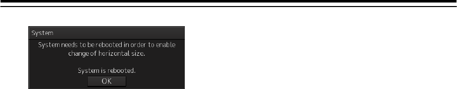
4-82
4 To change the display size, click on the [OK] button. To cancel the change, close the
dialog by clicking on the [x] button.
5 When the [OK] button is clicked on, the system is rebooted
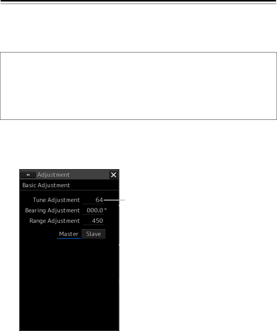
4-83
4.21 Tune Adjustment
[RADAR]
At installation or replacement of the magnetron, tuning adjustments of the transmitter and receiver
of the radar antenna are necessary.
Note
After replacement of the magnetron, perform rough tuning while the image is stable after
setting the radar to the Standby state for 20 to 30 minutes as the preheating time, operating
the radar from the short pulse range, and shifting the operation to the long pulse range
sequentially.
Disabled in radar Slave mode.
Not displayed when the solid-state radar antenna is connected.
1 Display the dialog of the Adjustment submenu.
2 Select [Basic Adjustment] in the Classification pane.
The "Basic Adjustment" dialog is displayed in the Edit pane.
3 Click on the [Tune Adjustment] input box.
A numeric keyboard is displayed.
4 Enter an adjustment value (0 to 127) in the input box so that the tuning bar indicates
the maximum level (the tuning bar touches the right-most position).
5 Click on the [x] button.
When the dialog is closed, the adjustment value is saved in the radar antenna.
[Tune Adjustment] input dialog box.
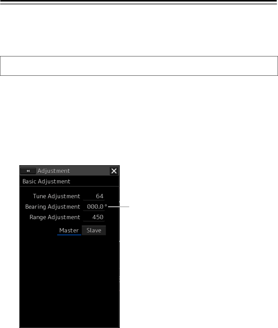
4-84
4.22 Bearing Adjustment
[RADAR][ECDIS]
Adjust the bearing so that the target measured by the compass of the ship on [Bearing Adjustment] of
the [Basic Adjustment] dialog and the bearing of the image displayed on the radar screen match.
Note
This function is disabled when the radar interswitch is set to the Slave mode.
1 Set the bearing mode to [H UP] and set the image processing mode to [Process Off].
2 Measure a bearing in the ship's heading direction of a suitable target (for instance,
halted ship, breakwater, and buoy) by using the compass on the ship.
3 Display the dialog of the Adjustment submenu.
4 Select [Basic Adjustment] in the Classification pane.
The "Basic Adjustment" dialog is displayed in the Edit pane.
5 Click on the [Bearing Adjustment] input box.
A numeric value input keyboard is displayed.
6 Input an adjustment value in the input box so that the bearing of the target that was
measured in Step 2 indicates a correct bearing. (0 to 359.9)
7 Click on the [X] button.
When the dialog is closed, the adjustment value is saved in the radar antenna.
[Bearing Adjustment] input box
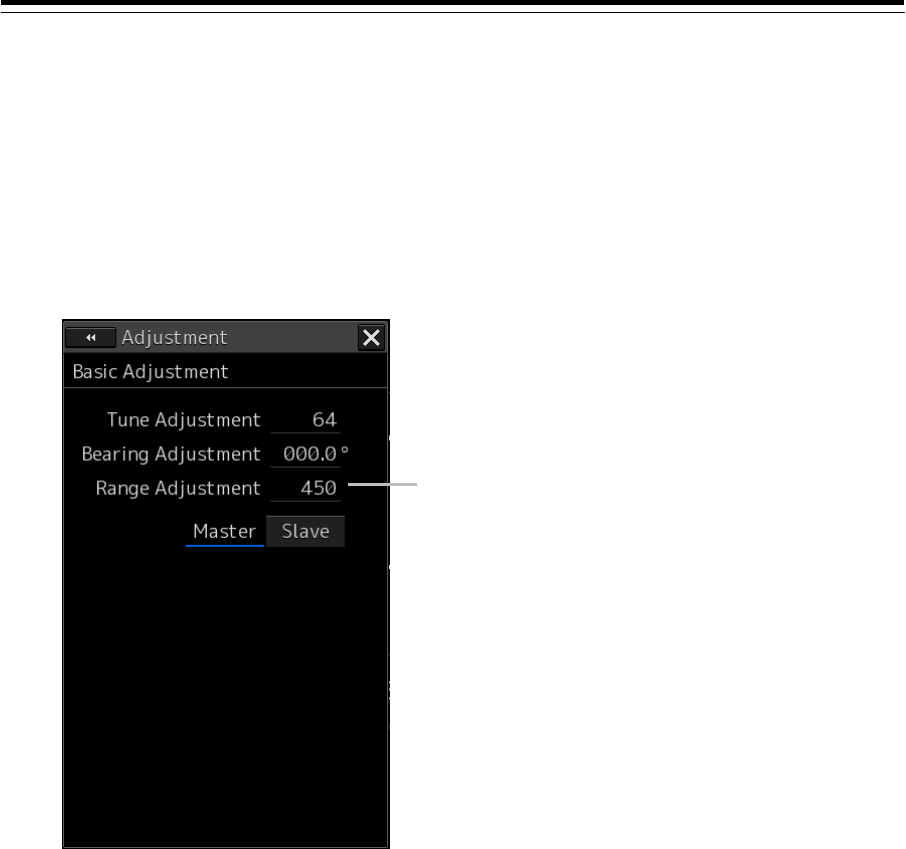
4-85
4.23 Range Adjustment
[RADAR][ECDIS]
Adjust the distance of the target on the screen so that the correct distance is displayed.
1 On the radar screen, specify a target whose distance is available in advance.
2 Display the dialog of the Adjustment submenu.
3 Select [Basic Adjustment] in the Classification pane.
The "Basic Adjustment" dialog is displayed in the Edit pane.
4 Click on the [Range Adjustment] input box.
A numeric input keyboard is displayed.
5 Enter an adjustment value in the input box so that the distance of the target specified
in Step 1 indicates the correct distance. (128 to 1024)
6 Click on the [X] button.
[Range Adjustment] input box
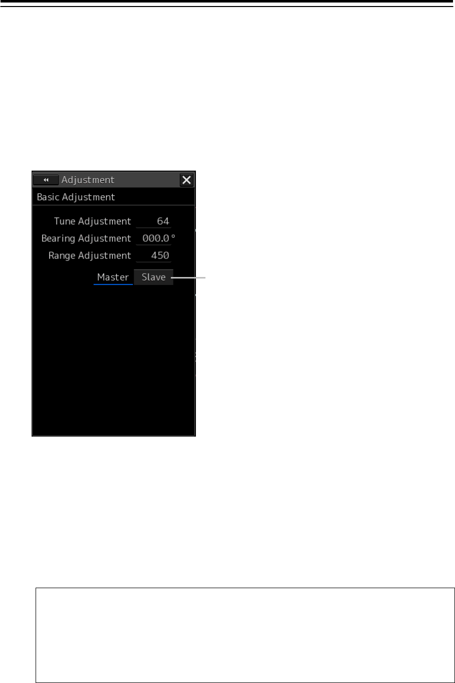
4-86
4.24 Master/Slave Radar Operation Mode
[RADAR][ECDIS]
Either the Master or Slave radar operation mode can be selected.
1 Display the dialog of the Adjustment submenu.
2 Select [Basic Adjustment] in the Classification pane.
The "Basic Adjustment" dialog is displayed in the Edit pane.
3 Click one of the radar operation mode buttons to select either the Master mode or the
Slave mode.
Master:
Can control the radar antenna.
Slave:
Cannot control the radar antenna. The display unit uses the radar signals controlled by the
master radar antenna.
Note
While in the Slave mode, the operation to control the radar antenna is disabled.
When ECDIS receives radar signals directly from the radar, set the radar operation
mode to Slave.
When ECDIS receives radar signals via interswitch, set the radar operation mode to
Master.
4 Click on the [X] button
Radar operation mode selection
button
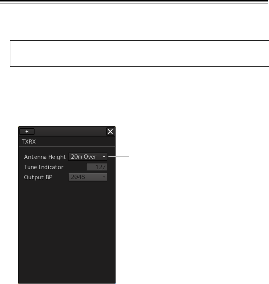
4-87
4.25 Setting an Antenna Height [RADAR][ECDIS]
Set a height of the antenna of a radar unit.
1 Measure the height from the sea surface to the antenna.
2 Display the dialog of the Adjustment submenu.
3 Select [TXRX] in the Classification pane.
The "TXRX" dialog is displayed in the Edit pane.
4 Select the setting value corresponding to the antenna height that was measured in
Step 1 from the [Antenna Height] combo box.
Under 5m (5m or less)
5-10m
10-20m
20m Over (20mm or more)
5 Click on the [X] button.
Note
Having once set the antenna height, do not change it unnecessarily.
[Antenna Height] combo box
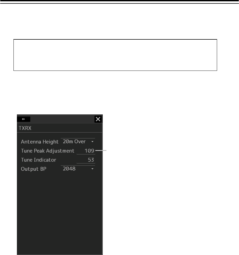
4-88
4.26 Tune Peak Adjustment
[RADAR]
Tune the transmitter and the receiver (using an antenna of 10kw).
1 Display the dialog of the Adjustment submenu.
2 Select [TXRX] in the Classification pane.
The "TXRX" dialog is displayed in the Edit pane.
3 Click on the [Tune Indicator] (tune indicator bar display) input box.
A numeric input keyboard is displayed.
4 Enter a setting value in the input box so that the tuning bar indicates the maximum
range (0 to 127).
5 Click on the [x] button.
When the dialog is closed, the adjustment value is saved in the radar antenna.
Note
This function is disabled in radar Slave mode.
Not displayed at connection of a solid state radar unit.
[Tune Peak Adjustment]
input box
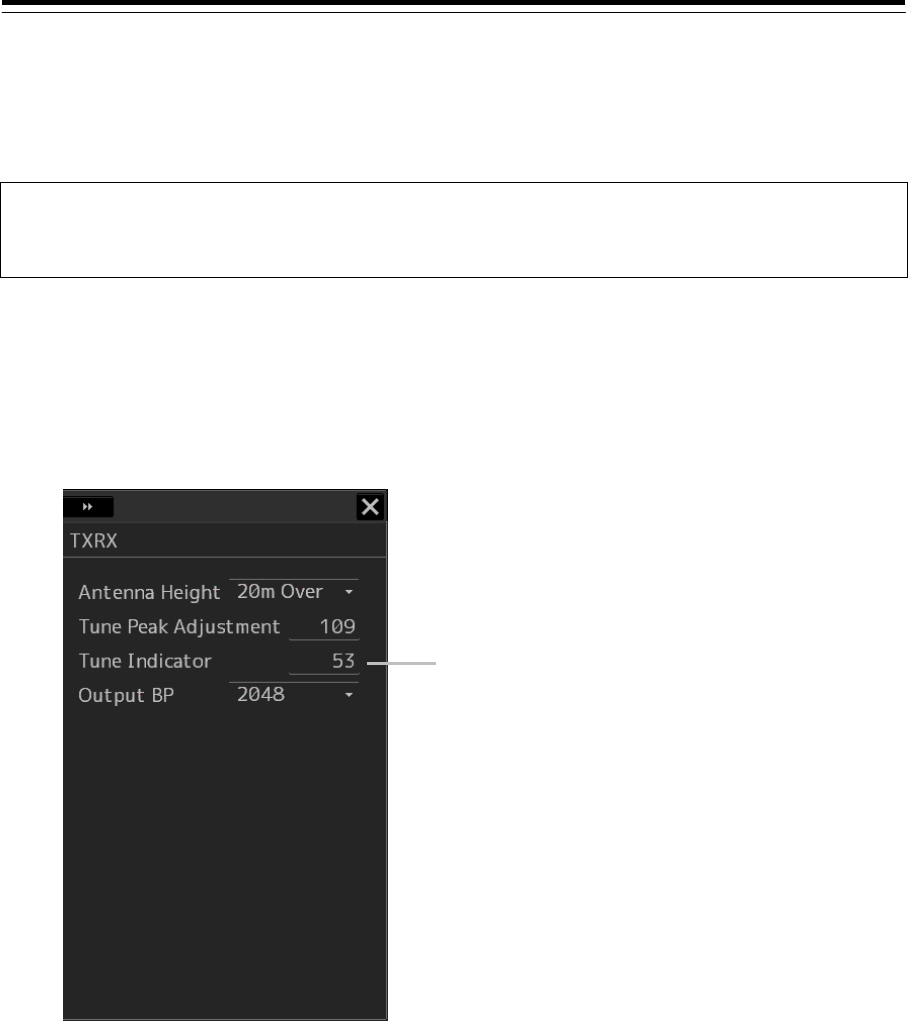
4-89
4.27 Setting a Tune Indicator (tuning
indicator level) [RADAR]
Set the scale when the tuning bar touches the peak value.
Note
This function is disabled under radar slave mode.
Not displayed when a solid-state radar antenna is connected.
1 Set the range to 48 nm or more.
2 Display the dialog of the Adjustment submenu.
3 Select [TXRX] in the Classification pane.
The "TXRX" dialog is displayed in the Edit pane.
4 Click on the [Tune Indicator] input box.
A numeric value input keyboard is displayed.
5 Input a setting value in the input box so that the tuning bar oscillates within the range
from 80% to 90% of the maximum amplitude position (0 to 127).
6 Click on the [x] button.
When the dialog is closed, the adjustment value is saved in the radar antenna.
[Tune Indicator] input box
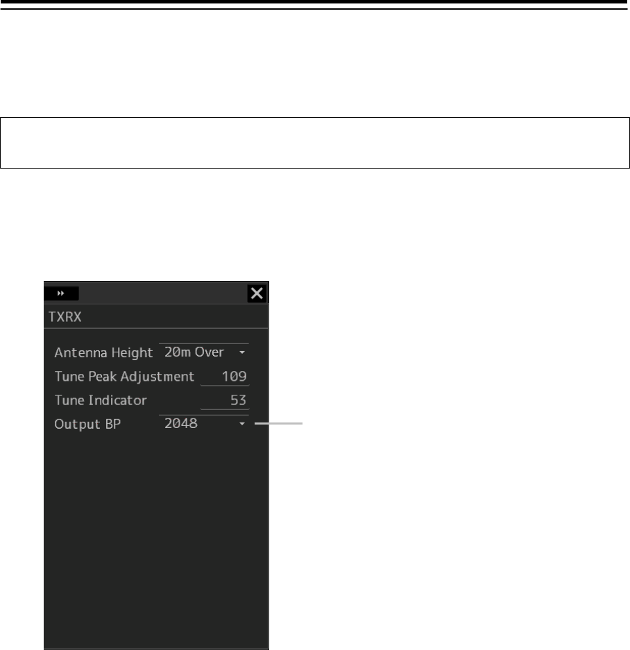
4-90
4.28 Setting Output BP (Radar Antenna
Bearing Pulse Output) [RADAR]
Note
Not selected when NKE-2103 type of radar antenna is connected.
1 Display the dialog of the Adjustment submenu.
2 Select [TXRX] in the Classification pane.
The "TXRX" dialog is displayed in the Edit pane.
3 Select a bearing pulse count that is output from the radar antenna from the [Output
BP] combo box (2048 or 4096).
4 Click on the [x] button.
[Output BP] combo box
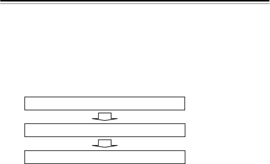
4-91
4.29 Performance Monitor Adjustment
[RADAR]
Adjust the radar transmission/reception state by using the "Performance Monitor" dialog (using
magnetron radar) or "Performance Monitor (SSR)" dialog (using solid-state radar). The items that are
displayed in the dialog vary according to the type of the radar antenna.
Flow of Performance Monitor Adjustment
Perform adjustment of a performance monitor according to the following procedures.
[Adjusting the transmission level and the receiving level.]
Adjust the performance monitor by the next explanation.
- Adjusting the monitor reception level of a magnetron radar unit
- Adjusting the monitor transmission level of the magnetron radar unit
- Adjusting the monitor reception level of the solid-state radar unit
- Adjusting the monitor transmission level of the solid-state radar unit
[Checking the state of a performance monitor]
Check the amount of attenuation by the next explanation after adjusting a performance
monitor.
- Checking the state of the performance monitor of the magnetron radar unit
- Checking the state of the performance monitor of the solid-state radar unit
[Entry of the amount of attenuation to the label]
Enter the amount of attenuation to the label by the next explanation.
- Entry of the amount of attenuation to the label
Adjusting the transmission level and the receiving level
Checking the state of a performance monitor
Entry of the amount of attenuation to the label
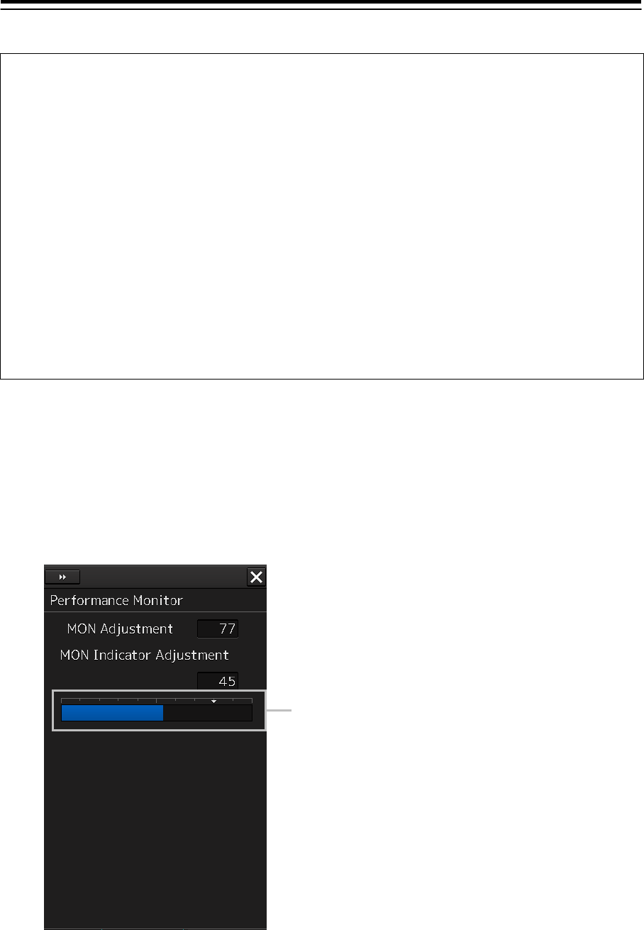
4-92
Note
When the radar is in the Slave mode, the "Performance Monitor" dialog (or "Performance
Monitor (SSR)" dialog is disabled.
If a master unit other than straight connection is being set in interswitch setting, the
"Performance Monitor" screen (or "Performance Monitor (SSR)" screen) is disabled (except
when [Controllable MON] is being set to [All] with [settings] - [interswitch] in the "Installation"
dialog box.
When the "Performance Monitor" dialog is displayed, the sector blank in the PPI screen is
hidden. When the solid state radar antenna is connected, the PM sector is displayed; in the
case of the magnetron radar, the sector is not displayed.
While adjusting the performance monitor, TGT acquisition is not canceled by the target
tracking function.
If a TGT symbol is displayed inside a pattern of the performance monitor and adjusting is
difficult, cancel TGT acquisition once.
Adjusting the monitor reception level of a magnetron radar unit
Adjust the circuit that monitors the reception performance of the magnetron radar unit.
1 Display the dialog of the Adjustment submenu.
2 Select [MON] in the Classification pane.
The "Performance Monitor" dialog is displayed in the Edit pane.
3 Click on the [MON Adjustment] (MON reception level adjustment) input box.
A numeric value input keyboard is displayed.
Performance monitor level
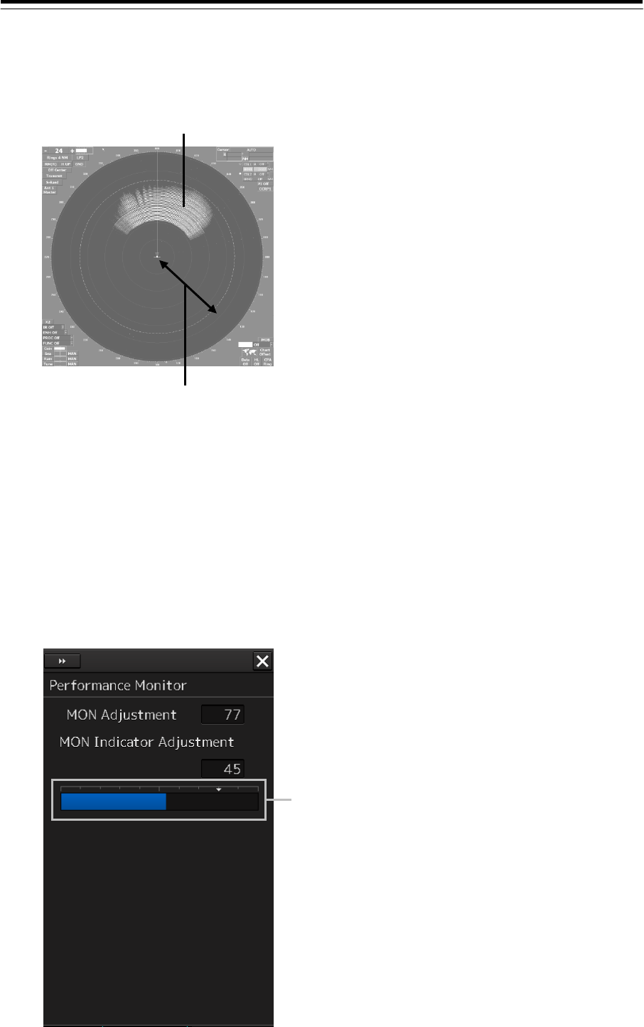
4-93
4 Enter a setting value in the input box so that the farthest position of the performance
monitor pattern becomes 18.00 NM. (0 to 127)
5 Click on the [x] button.
When the dialog is closed, the adjustment value is saved in the radar antenna.
Adjusting the monitor transmission level of the magnetron radar unit
Adjust the circuit that monitors the transmission performance of the magnetron radar unit.
1 Display the dialog of the Adjustment submenu.
2 Select [MON] in the Classification pane.
The "Performance Monitor" dialog is displayed in the Edit pane.
18.00NM
Performance monitor pattern
Performance monitor level display
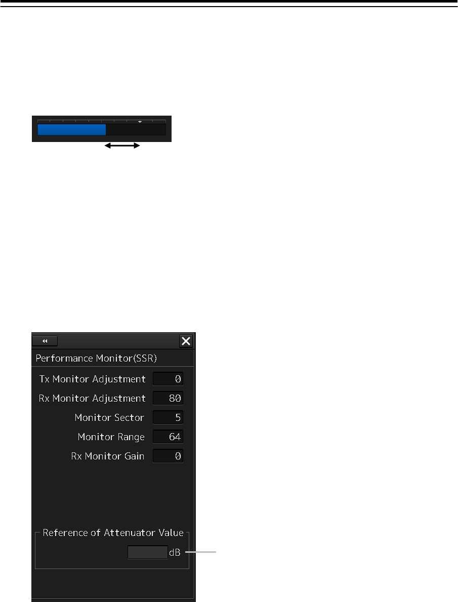
4-94
3 Click on the [MON Indicator Adjustment] input box.
A numeric value input keyboard is displayed.
4 Enter a setting value in the input box so that "8" is displayed as the performance
monitor level (0 to 127).
5 Click on the [x] button.
When the dialog is closed, the adjustment value is saved in the radar antenna.
Adjusting the monitor transmission level of the solid-state radar unit
Adjust the circuit that monitors the transmission performance of the solid-state radar unit.
1 Display the dialog of the Adjustment submenu.
2 Select [MON] in the Classification pane.
The "Performance Monitor (SSR)" dialog is displayed in the Edit pane.
3 Click on the [TX Monitor Adjustment] input box.
A numeric input keyboard is displayed.
The value displayed in [Reference of Attenuator Value] is used as the transmission
attenuator value.
4 Enter a setting value in the input box so that the display of [Reference of Attenuator
Value] indicates "0.0±1.0dB" (0 to 127).
Adjust to 8.
[Reference of Attenuator Value] display
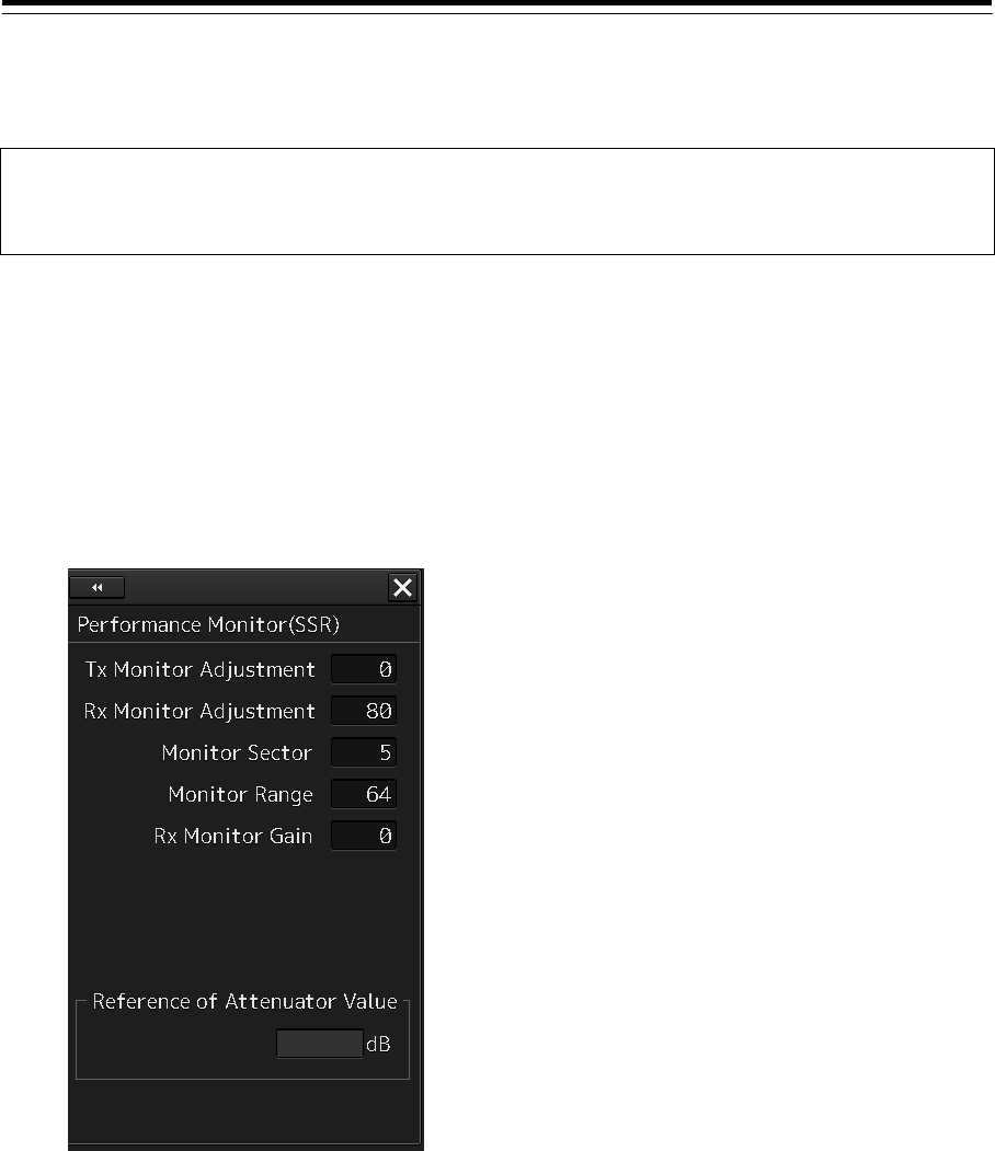
4-95
5 Click on the [x] button.
When the dialog is closed, the adjustment value is saved in the radar antenna.
Note
Do not change the values set in the [Monitor Range] input box and the [RX Monitor Gain] (reception
monitor gain) input box.
Adjusting the monitor reception level of the solid-state radar unit
Adjust the circuit that monitors the reception performance of the solid-state radar unit.
1 Display the dialog of the Adjustment submenu.
2 Select [MON] in the Classification pane.
The "Performance Monitor (SSR)" dialog is displayed in the Edit pane.
3 Click on the [Monitor Sector] input box.
A numeric input keyboard is displayed.
The value displayed in [Reference of Attenuator Value] is used as the reception attenuator
value.
4 Enter a setting value in the input box so that the display of [Reference of Attenuator
Value] indicates the maximum value.
5 Click on the [RX Monitor Adjustment] input box.
6 Enter a setting value in the input box so that the display of [Reference of Attenuator
Value] indicates "0.0±1.0dB" (0 to 127).
A numeric input keyboard is displayed.
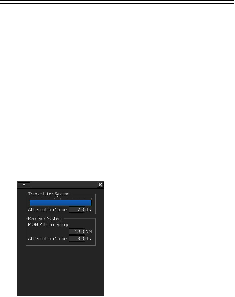
4-96
7 Click on the [x] button.
When the dialog is closed, the adjustment value is saved in the radar antenna.
Note
The values set in the [Monitor Range] input box and the [RX Monitor Gain] input box must not be
changed.
Checking the state of the performance monitor of the magnetron radar unit
The state of the performance monitor of a magnetron radar unit is checked.
Note
Close the "Performance Monitor" dialog, when the dialog is being displayed, and end adjustment of
a performance monitor.
1 Display the dialog of the Maintenance - Diagnosis submenu.
2 Select [MON Check] in the Classification pane.
The "MON Check" dialog is displayed in the Edit pane.
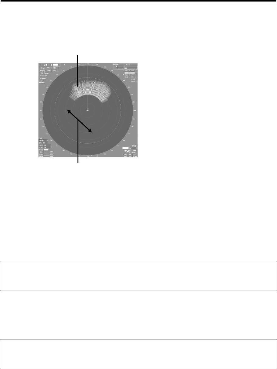
4-97
3 Turn the [VRM] dial so that the farthest position of the performance monitor pattern
becomes 18.00 NM.
4 Check the amount of attenuation in the dialog box.
Benchmarks for the amount of attenuation are as follows:
Attention Value of Transmitter:
At normal: -6.9 dB to +2.0 dB
At degrading performances: -15.0 dB to -7.0 dB
Attention Value of Receiver:
At normal: -2.9 dB to +3.5 dB
At degrading performances: -15.0 dB to -3.0 dB
Note
When confirming the attenuation value of the transmitter, after opening the dialog box, wait for one
minute, and then read its value.
Checking the state of the performance monitor of the solid-state radar unit
The state of the performance monitor of a solid-state radar unit is checked.
Note
Close the "Performance Monitor(SSR)" dialog, when the dialog is being displayed, and end
adjustment of a performance monitor.
1 Display the dialog of the Maintenance - Diagnosis submenu.
Performance monitor pattern
18.00NM
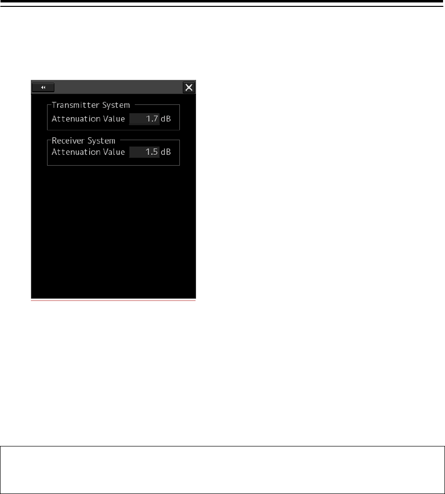
4-98
2 Select [MON Check(SSR)] in the Classification pane.
The "MON Check(SSR)" dialog is displayed in the Edit pane.
3 Verify the attenuation of the transmission unit and reception unit of the system.
The guideline of the attenuation is as follows.
Attenuation of the transmission unit:
Normal : -6.9dB ~ +7.0dB
Performance deterioration: -20.0dB ~ -7.0dB
Attenuation of the reception unit:
Normal:-6.9dB ~ +7.0dB
Performance deterioration: -20.0dB ~ -7.0dB
Note
To verify the attenuation of the transmission unit, read the value displayed one minute after
the dialog is opened.
Entry of the amount of attenuation to the label
Entry of the amount of attenuation to the “PERF.MONITOR INFORMATION LABEL” label after
adjusting a performance monitor.
1 Enter the following contents to the “PERF.MONITOR INFORMATION LABEL” label.
DATE: The date which adjusted.
TX VALUE: The amount of attenuation of transmitter system.
RX VALUE: The amount of attenuation of receiver system.
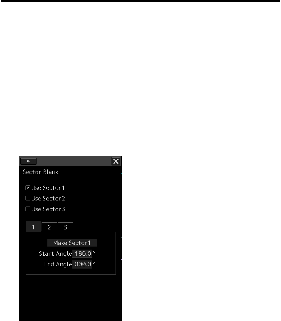
4-99
4.30 Setting Sector Blank (RADAR Screen
Only) [RADAR]
The sector blank is an area that has been set up by specifying a fan-shaped range (sector), stopping
the transmission in that bearing, and hiding radar echoes. The sector blank runs in the relative bearing
using the ship's heading as reference.
Three types of sectors can be set up (sector blanks 1/2/3).
Note
Disabled in radar Slave mode.
1 Display the dialog of the Adjustment submenu.
2 Select [Sector Blank] in the Classification pane.
The "Sector Blank" dialog is displayed in the Edit pane.
3 Select sector blank to be set by checking [Use Sector1/2/3] (using sector blank 1/2/3).
4 Click on the [Make Sector1/2/3] (creating sector blank 1/2/3) button that corresponds
to the sector blank number that was selected in Step 1.
The cursor is set to the sector blank 1/2/3 creation mode.
5 Draw sector blank with the cursor.
The following information items are displayed regarding the sector blank that is being
created.
Start Angle: Sector blank starting angle
End Angle: Sector blank ending angle
6 Click on the [x] button.
When the dialog is closed, the adjustment value is saved in the radar antenna.
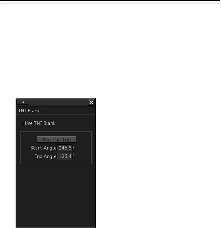
4-100
4.31 Setting TNI Blank
[RADAR]
It is possible to create TNI Blank and use it as a sector.
Note
Disabled in radar Slave mode.
Not displayed at connection of a sold-state radar unit.
1 Display the dialog of the Adjustment submenu.
2 Select [TNI Blank] in the Classification pane.
The "TNI Blank" dialog is displayed in the Edit pane.
3 Select the [Use TNI Blank] check box.
4 Click on the [Make Sector] button.
The cursor mode is set to the TNI blank creation mode.
5 Draw TNI blank using the cursor.
The following information is displayed for the TNI blank that is being created.
Start Angle: TNI blank starting angle
End Angle: TNI blank ending angle.
6 Click on the [x] button.
When the dialog is closed, the adjustment value is saved in the radar antenna.
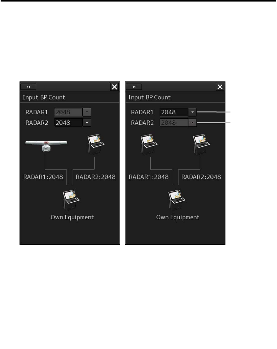
4-101
4.32 Setting Input BP Count [RADAR][ECDIS]
Set a bearing pulse count to be input from radar 1 or radar 2.
1 Display the dialog of the Adjustment submenu.
2 Select [Input BP Count] in the Classification pane.
The "Input BP Count" dialog is displayed in the Edit pane.
3 Select an input bearing pulse count in the [RADAR1/2] box (360/415/830/1024/
2048/4096). Alternatively, display a numeric input dialog by clicking on the box and
enter an input bearing pulse count (360 to 4096).
Note
The [RADAR1] combo box is disabled under the Master unit.
When the output BP count is set to a value other than 2048 or 4096 in the Slave unit, only
2048 or 4096 can be selected from the [RADAR1] combo box.
Either or (both) of the input BP count and the output BP count of the Slave unit must be set to
2048 or 4096.
4 Click on the [x] button.
[RADAR1] box
[RADAR2] box
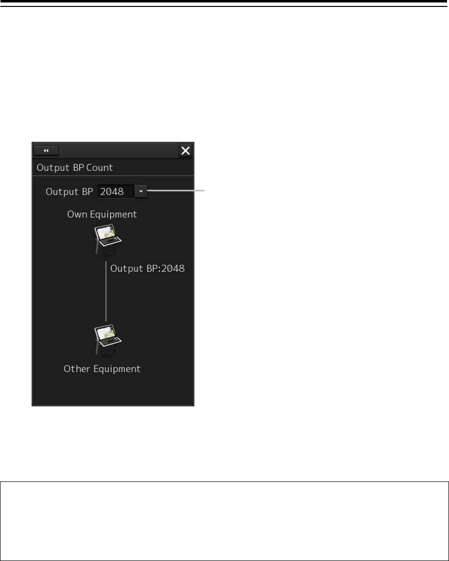
4-102
4.33 Setting Output BP Count [RADAR]
Set a bearing pulse count to be output to the Slave unit.
1 Display the dialog of the Adjustment submenu.
2 Select [Output BP Count] in the Classification pane.
The "Output BP Count" dialog is displayed in the Edit pane.
3 Select an output bearing pulse count in the [Output BP] box
(360/415/830/1024/2048/4096). Alternatively, display a numeric input dialog by clicking
on the box and enter an output bearing pulse count (360 to 4096).
Note
When the input BP count is set to a value other than 2048 or 4096 in the Slave unit, only 2048
or 4096 can be selected from the [Output BP] combo box.
Either or (both) of the input BP count and the output BP count of the Slave unit must be set to
2048 or 4096.
4 Click on the [x] button.
[Output BP] box
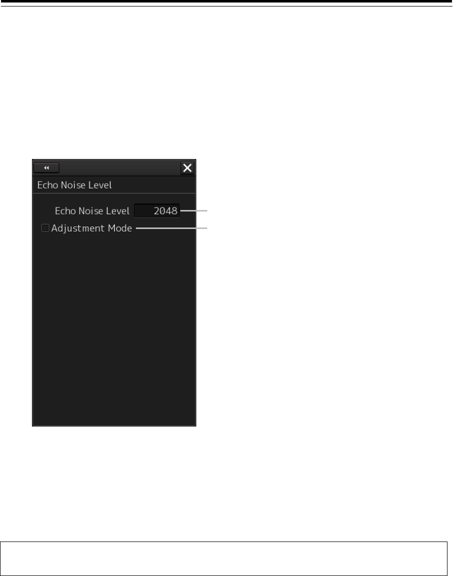
4-103
4.34 Echo Noise Level Adjustment
[RADAR][ECDIS]
Adjust the level of the noise contained in radar echo.
1 Display the dialog of the Adjustment submenu.
2 Select [Echo Noise Level] in the Classification pane.
The "Echo Noise Level" dialog is displayed in the Edit pane.
3 Select the [Adjust Mode] check box.
4 Click on the [Echo Noise Level] input box.
A numeric input keyboard is displayed.
5 Enter a numeric value of around 2200 (1960 at factory delivery).
Note
This setting has been adjusted at factory delivery. Do not change the setting unnecessarily.
6 Reduce the value in the [Echo Noise Level] input box while checking the monitor
and record the value at which the radar image is filled with yellow for the first time.
7 Enter the value that is calculated by subtracting 80 from the recorded value
(permissible range:0 ~ 4095).
8 Click on the [x] button.
[Adjustment Mode] check box
[Echo Noise Level] input box
4-104
4.35 TT (Target Tracking) Function Adjustment
(RADAR Screen Only)
[RADAR]
Adjust the following TT function parameters by using the "TT" dialog.
Vector constant
Quantization level
Gate size used for tracking
TT limit ring
What is quantization level?
A quantization level is a signal level that is recognized by the TT function as a target.
By setting a lower value, input of signals of weak targets in the ARPA target detection circuit is enabled.
However, many unnecessary signals are also input, destabilizing acquisition and tracking of targets
due to unnecessary signals. It is important to set a value greater than the value for detecting
unnecessary signals by 4 or 5.
Do not change the quantization level settings indiscreetly. If
inappropriate values are set, the acquisition of the target tracking
function and the tracking function will deteriorate, possibly causing
accidents.
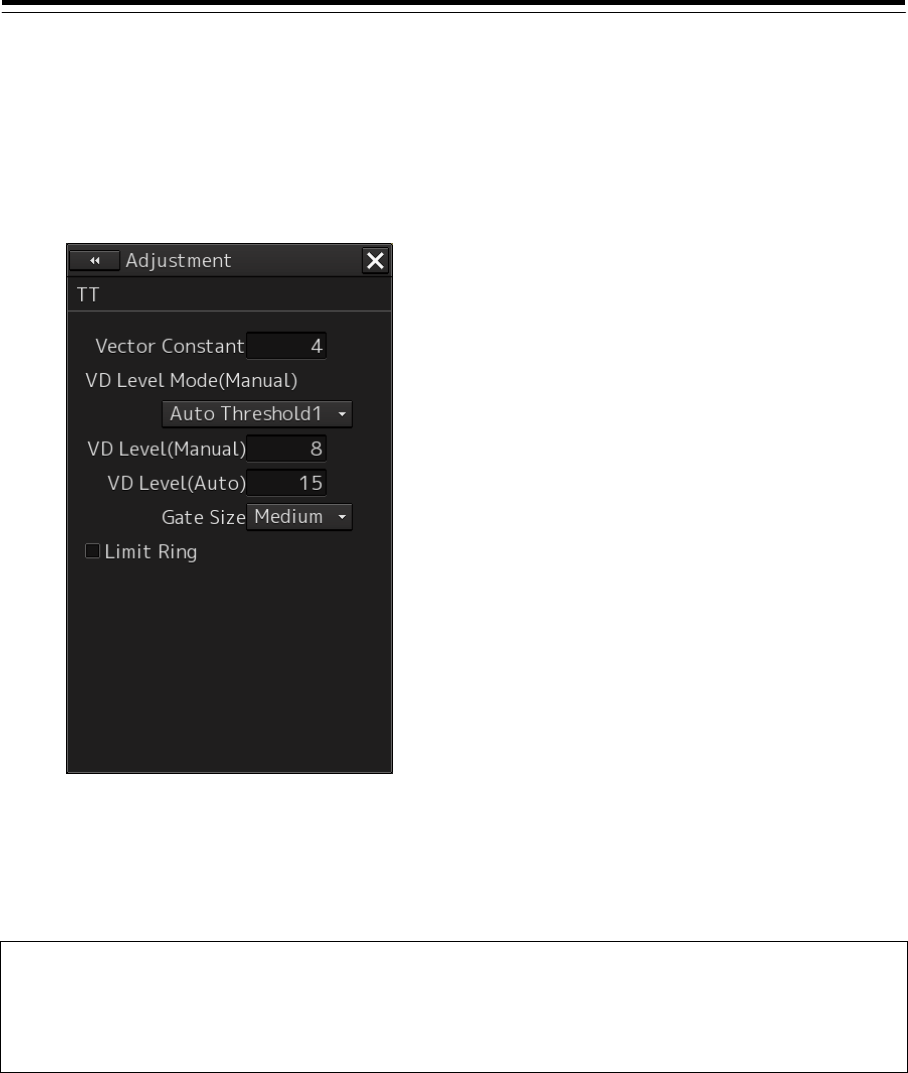
4-105
Setting vector constants
Adjust the vector tracking performance of the target tracking function.
1 Display the dialog of the Adjustment submenu.
2 Select [TT] in the Classification pane.
The "TT" dialog is displayed in the Edit pane.
3 Click on the [Vector Constant] input box.
A numeric input keyboard is displayed.
4 Enter a setting value in the input box.
Note
Do not change this setting unnecessarily. Normally, set 4 for [Vector Constant]. By increasing the
value of [Vector Constant], tracking of the target vector can be improved when the target and own
ship changes the course or speed. However, note that the vector precision deteriorates.
5 Click on the [x] button.
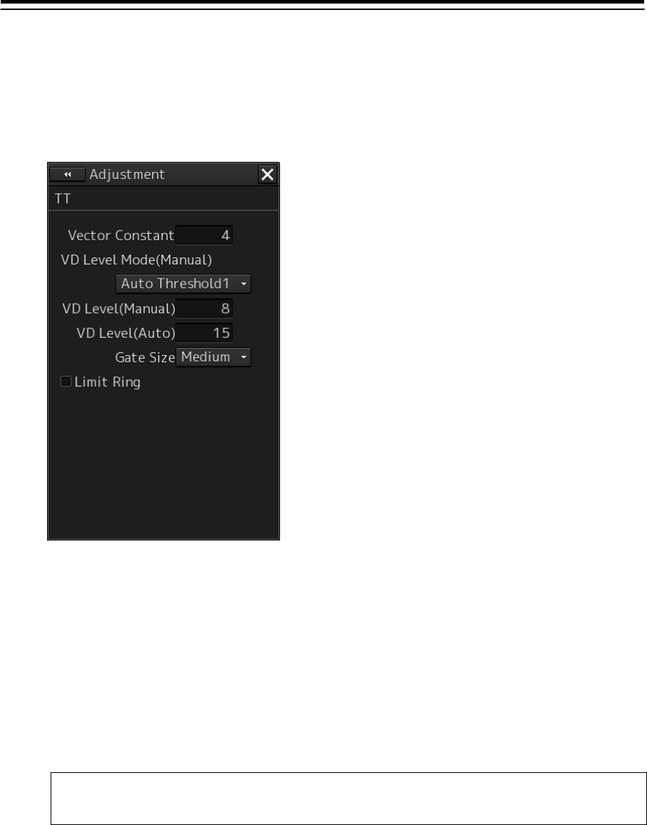
4-106
Setting quantization levels at manual acquisition
1 Display the dialog of the Adjustment submenu.
2 Select [TT] in the Classification pane.
The "TT" dialog is displayed in the Edit pane.
3 Select a quantization threshold value at manual acquisition from the [VD Level Mode
(Manual)] (quantization mode at manual acquisition) combo box.
Auto Threshold1
Auto Threshold2
Manual Threshold
4 Click on the [VD level (Manual)] (quantization level at manual acquisition) input box.
A numeric input keyboard is displayed.
5 Enter a setting value in the input box (0 to 255).
Note
Do not change this setting unnecessarily.
6 Click on the [x] button.
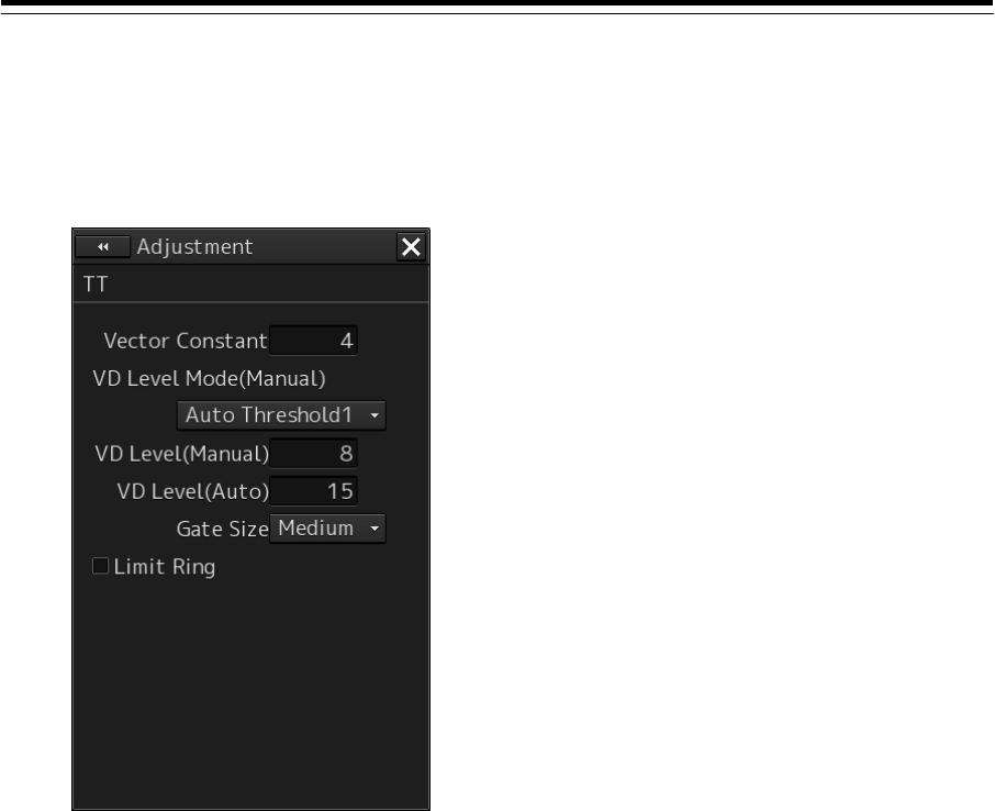
4-107
Setting quantization levels at automatic acquisition
1 Display the dialog of the Adjustment submenu.
2 Select [TT] in the Classification pane.
The "TT" dialog is displayed in the Edit pane.
3 Click on the [VD Level (Auto)] (quantization level at automatic acquisition) input box.
A numeric input keyboard is displayed.
4 Enter a setting value in the input box (0 to 255).
5 Click on the [x] button.
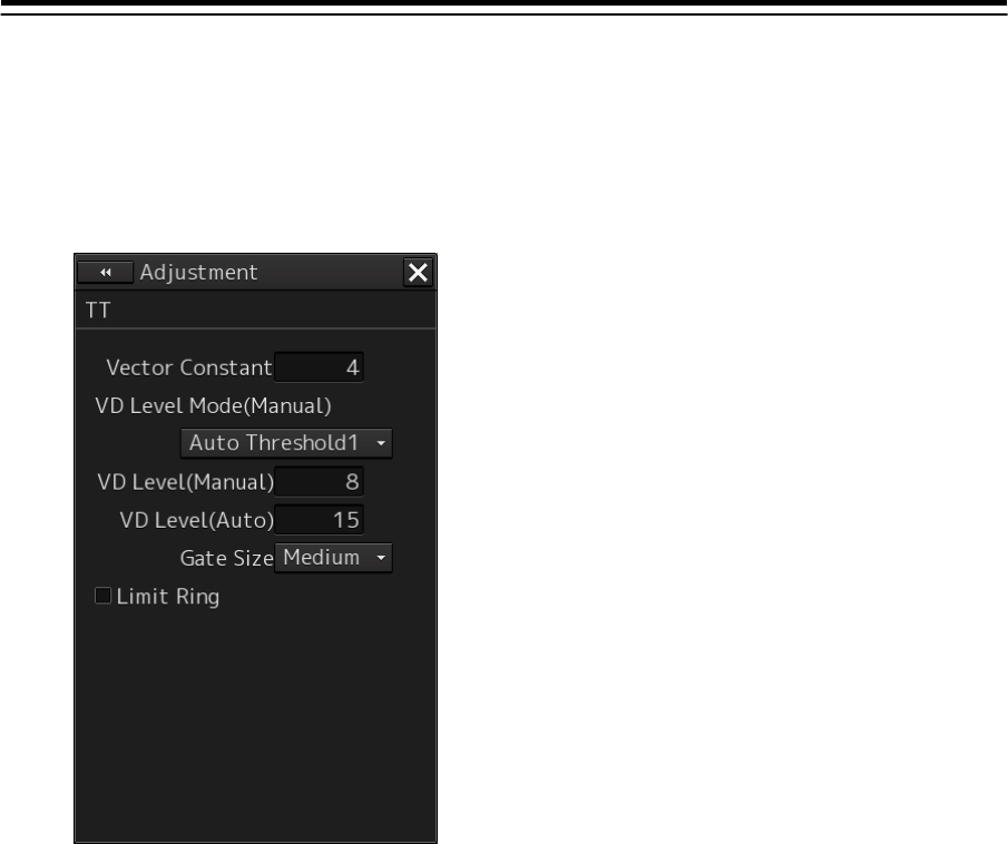
4-108
Setting a gate size to be used for tracking
1 Display the dialog of the Adjustment submenu.
2 Select [TT] in the Classification pane.
The "TT" dialog is displayed in the Edit pane.
3 Select a gate size from the [Gate Size] combo box.
- Small
- Medium
- Large
4 Click on the [x] button.

4-109
Displaying a TT limit ring
1 Display the dialog of the Adjustment submenu.
2 Select [TT] in the Classification pane.
The "TT" dialog is displayed in the Edit pane.
3 To display a TT limit ring, select the [Limit Ring] check box.
4 Click on the [x] button.
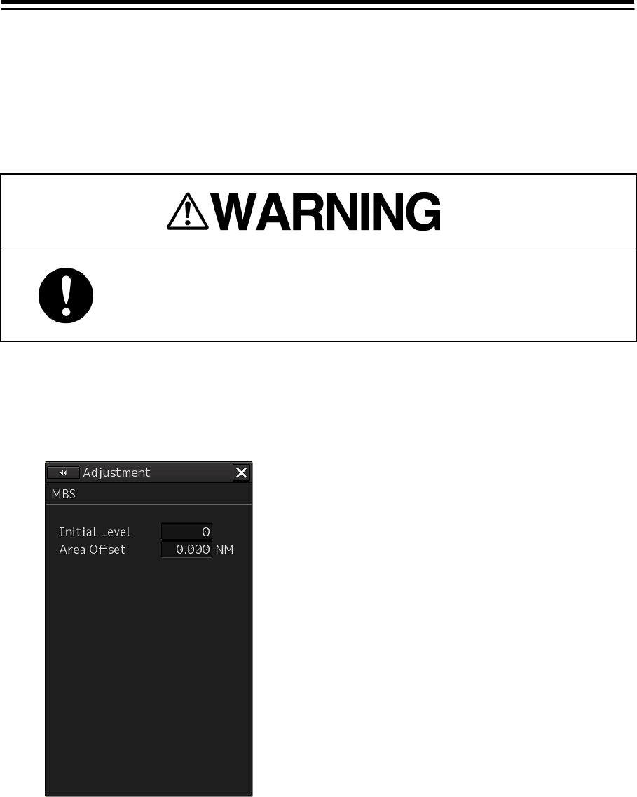
4-110
4.36 Adjusting MBS
[RADAR][ECDIS]
MBS (Main Bang Suppression) adjustment is to adjust a display unit processing circuit in order to
suppress main bang, which is the reflection signal from a microwave transmission circuit of a
waveguide that normally appears as an image of a circle at the center of the radar screen.
Perform MBS adjustment by using the "MBS" dialog.
Do not change this setting indiscreetly.
If wrong adjustment is performed, the nearest target will be erased,
causing collision to lead to death or serious injury.
1 Display the dialog of the Adjustment submenu.
2 Select [MBS] in the Classification pane.
The "MBS" dialog is displayed in the Edit pane.
3 Click on the [Initial Level] (MBS initial level) input box.
A numeric value input keyboard is displayed.
4 Enter an initial level of MBS so that the image of main bang becomes optimum (faint
image remains on the screen). (0 to 1023)
5 Click on the [Area Offset] (MBS area offset) input box.
A numeric value input keyboard is displayed
6 Enter a MBS area offset value (-0.200 ~ 0.200[NM]) so that the image of the main bang
becomes the optimum (remains lightly on the screen).
7 Click on the [x] button.
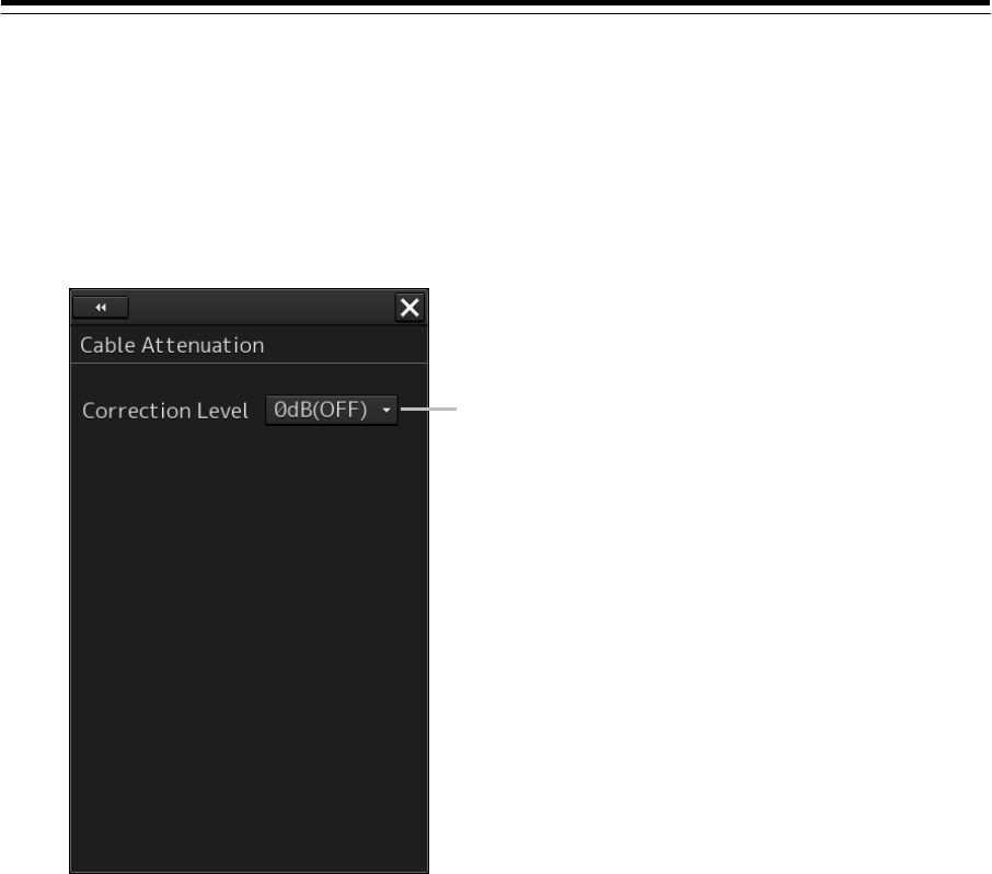
4-111
4.37 Setting Cable Attenuation
[ALL]
Set an attenuation correction level of the radar video signal level by the cable.
1 Display the dialog of the Adjustment submenu.
2 Select [Cable Attenuation] in the Classification pane.
The "Cable Attenuation" dialog is displayed in the Edit pane.
3 Select a correction level from the [Correction level] combo box (0dB (OFF)
2dB/4dB/6dB).
Select an appropriate level from the connected cable and the length by using “Determining
the attenuation correction level” that is described below.
4 Click on the [x] button.
[Correction Level] combo box

4-112
Determining the attenuation correction level
Perform the following procedure for the antenna for which cable attenuation is to be set.
1 Record the types and lengths of all the cables that are installed and used from the
antenna to the display.
In the environment where ISW is used, as the cable from the display to ISW is structured in two
way mode, a double length is required.
2 Read the attenuation correction level corresponding to the installed cable that is
recorded from the following correspondence table.
Cable installed Cable length [m] Attenuation correction level [dB]
CFQ-6912
- 20 0
20 - 35 2
35 - 50 4
50 - 6
2695110056
or
2695111153
- 25 0
25 - 50 2
50 - 75 4
75 - 6
RG-10/UY
(2661111153)
- 70 0
70 - 140 2
140 - 210 4
210 - 6
3 Select the total value of attenuation correction levels of all the cables that are
installed.
If the value is 6dB or more, use 6dB.
4 If ISW is available, perform the above procedure by changing the antenna to be set.
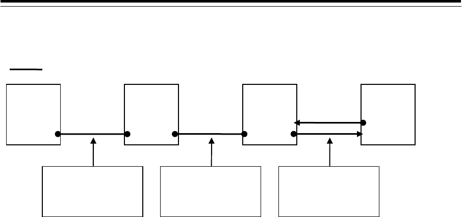
4-113
(Example)
For the following configuration, select 6dB (=4dB+2dB+0dB).
Antenna Indicato
r
Power
control
ISW
Cable: 2695110056
Length: 60 m
Attenuation
correction level: 4 dB
Cable: RG-10/UY
Length: 80 m
Attenuation
correction level: 2 dB
Cable: 2695111153
Length: 10 m
(5-m two way cable)
Attenuation
correction level: 0 dB
Connecting cable
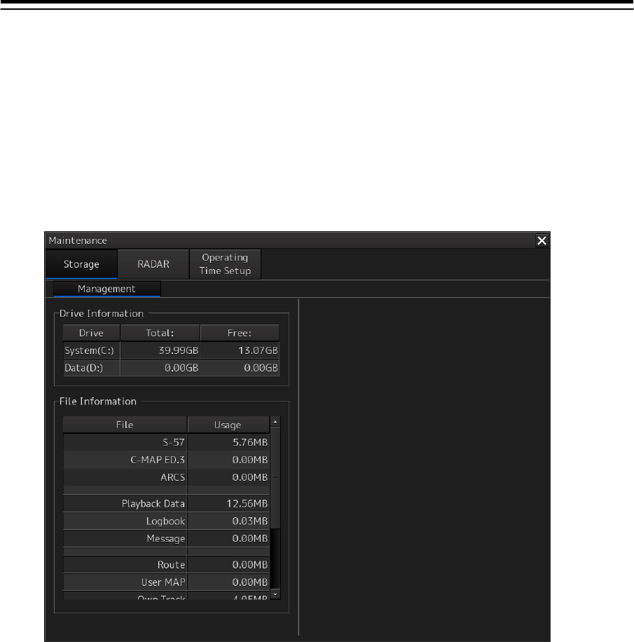
4-114
4.38 Verifying Storage
[ALL]
Use the "Management" dialog to verify the storage that is used.
1 Display the dialog of the Maintenance submenu.
2 Select [Storage] in the 1st Classification pane and [Management] in the 2nd
Classification pane.
The "Management" dialog is displayed in the Edit/Result pane.
The total storage capacity and free space on each of the drives (C and D) are displayed in the [Drive
Information] list. The capacity of each of the files stored on the drives is displayed in the [File
Information] list. The files managed by File Manager are applicable.
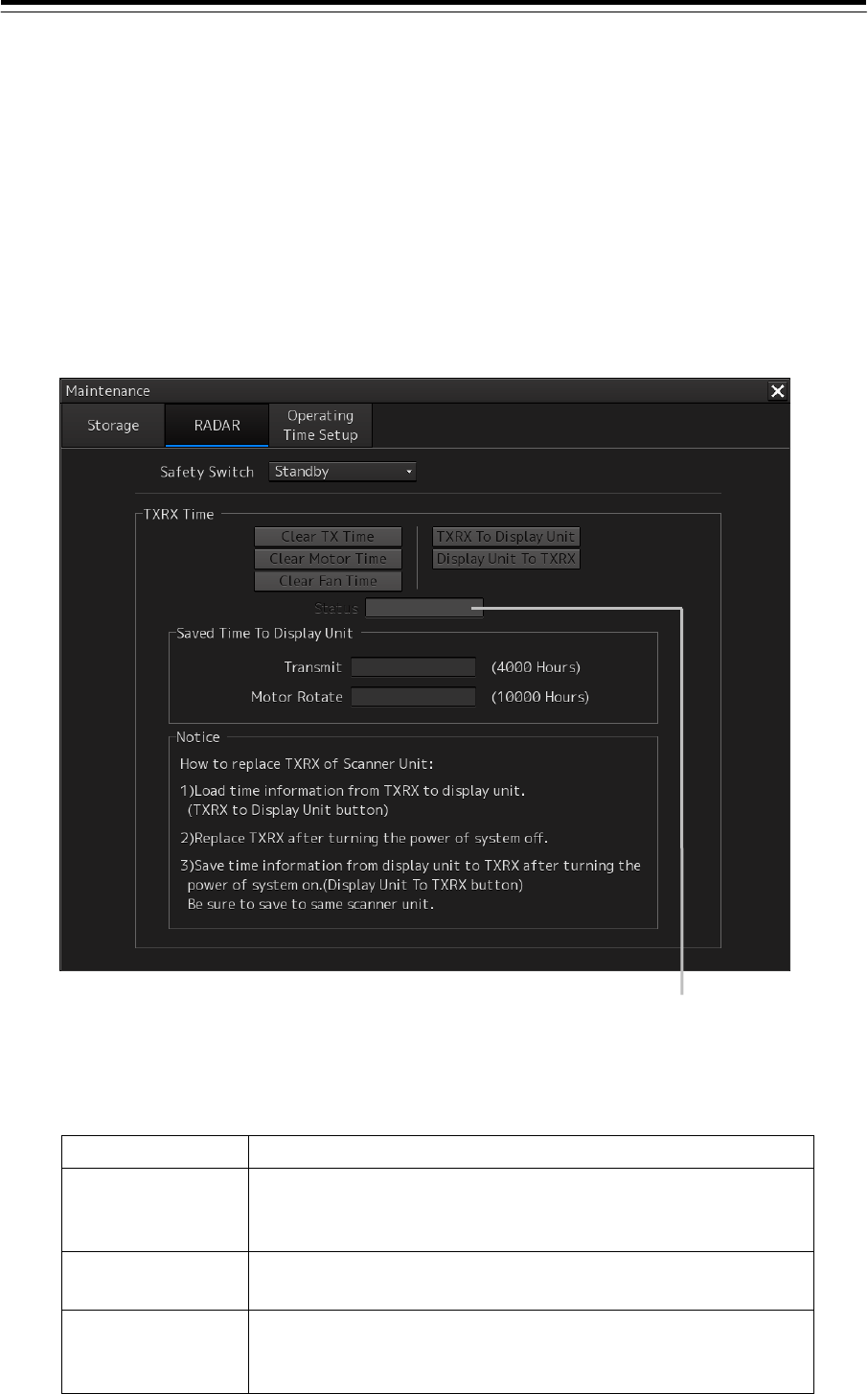
4-115
4.39 RADAR Adjustment (RADAR Screen
Only) [RADAR]
Use the "RADAR" dialog to maintain the radar.
Displaying the "RADAR" dialog
1 Display the dialog of the Maintenance submenu.
2 Select [RADAR] in the Classification pane.
The RADAR dialog is displayed in the Edit/Result pane.
Changing the operation mode of the safety switch
Open the list of the [Safety Switch] box and select the operation to be performed when the safety
switch of the radar antenna is set to OFF.
Setting Operation
TX-Off • No radiant section's rotation and transmission
• PPI screen transmission status
• Maintains the transmitting state without generating BP or BZ alarm
Standby
• No radiant section's rotation and transmission
• PPI screen standby
TX-On • No radiant section's rotation, with transmission
• PPI screen transmission status
• Maintains the transmitting state without generating BP or BZ alarm
Transmission result display

4-116
Clearing a radar antenna operation time
The total transmission time, total motor rotation time, and the total fan rotation time of the radar
antenna can be cleared.
Clearing the total transmission time of a radar antenna
Click on the [Clear TX Time] (resetting transmission time) button.
Clearing the total motor rotation time of a radar antenna
Click on the [Clear Motor Time] (resetting the motor rotation time) button.
Clearing the total fan rotation time of a radar antenna
Click on the [Clear Fan Time] (resetting the fan rotation time) button.
Replacing a TXRX circuit of a radar antenna
Check the total transmission time and the total motor rotation time and total fan rotation time of the
radar antenna and use the information as the guideline for replacement.
Acquiring the data of the total transmission time, total motor rotation time, and total fan
rotation time from the antenna
1 Click on the [TXRX To Display Unit] (transmitting from a radar antenna to a display
unit) button.
The data of the total transmission time, the total motor rotation time and total fan rotation
time is acquired from the radar antenna and is stored in a display unit. The time that is
acquired is displayed on the [Saved Time To Display Unit] display section.
Transmit: Total time acquired from the radar antenna
Motor Rotate: Total motor rotation time acquired from the radar antenna
FAN time: Total fan rotation time acquired from the radar antenna
Saving the data of the total transmission time, total motor rotation time, and total fan rotation
time in the radar antenna
1 Click the [Display Unit To TXRX] button (transmission from the display unit to the
radar antenna).
The total transmission time and total motor ration time and total fan rotation time saved in the
display unit are saved to the radar antenna.
If data is saved normally, the data saved in the display unit will be deleted.
When a command is sent from the display unit to the radar antenna, the transmission result is
displayed as follows.
Result waiting state: "Sending..." is displayed blinking at intervals of 1 sec.
When the result is success: "Completed" is displayed.
When the result is failure: "Not Completed" is displayed.

4-117
Replacing a TXRX circuit
The operation procedure and notes are displayed on the Notice display.
1 By clicking on the [TXRX To Display Unit] button, load the data of the total
transmission time and the total motor rotation time from the radar antenna to the
display unit.
2 Turn off the power of the system and replace the TXRX circuit.
3 Turn on the power of the system and write the data of the total transmission time and
the total motor rotation time in the transceiver unit of the radar antenna by clicking on
the [Display Unit To TXRX].
Note
Make sure that data is written to the transceiver unit of the same radar antenna when the data
is loaded.
A total fan rotation time is acquired and saved for a solid state antenna only.
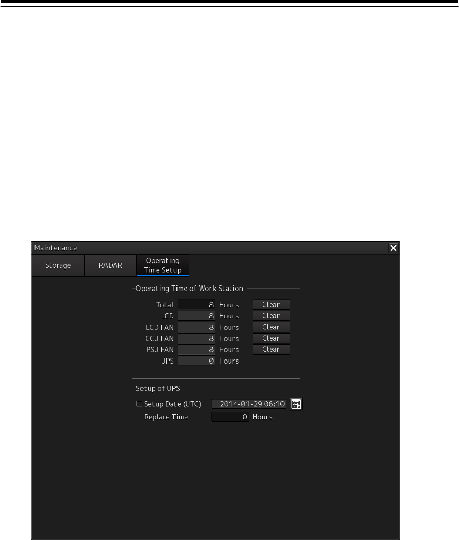
4-118
4.40 Operating Time Setup [ALL]
Use the "Operating Time Setup" dialog to specify a total operating time of the work station and verify
the operating time of each installation.
When UPS is connected to the work station, the guideline of the replacement timing can be checked by
registering the UPS installation date and time.
Displaying the "Operating Time Setup" dialog
1 Display the dialog of the Maintenance submenu.
2 Select [Operating Time Setup] in the Classification pane.
The "Operating Time Setup" dialog is displayed in the Edit/Result pane.
The operating times of the following installations are displayed.
• LCD
• LCD FAN
• CCU FAN
• PSU FAN
• UPS
Entering an operating time of the work station
1 Click on the [Total] (total time) input box in the [Operating Time of Work Station].
A numeric input keyboard is displayed.
2 Enter a total operating time of the display unit (0 to 999999 hours).
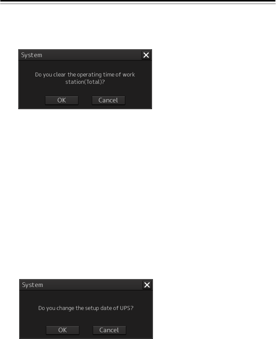
4-119
Clearing the time that is currently displayed
1 Click on the [Clear] button on the right side of the operating time display.
The dialog for verifying execution of clearing is displayed.
2 To clear the time, click on the [OK] button. To cancel the clearing, click on the
[Cancel] button.
Changing UPS installation date and time
1 Click on the calendar button.
A calendar is displayed.
2 Set a year and a month by using the year selection spin button and the month
selection spin button.
3 Click on the date to be set from the date selection box.
4 Set a time by clicking on the time spin button of the time picker.
5 Click on the [OK] button.
The setting is completed and the calendar is closed.
A dialog for confirming the change of the installation date and time is displayed.
6 To change the installation date and time, click on the [OK] button. To cancel the
change, click on the [Cancel] button.
The UPS installation date and time is displayed in [Setup Date (UTC)].
7 Select the [Setup Date (UTC)] (installation date and time) check box in the [Setup of
UPS] section.

4-120
Changing the UPS replacement time
Normally, it is not necessary to change the UPS replacement time. As the exception, when the
UPS of a different replacement time is used, input of the replacement time is necessary. An alert
can be generated at an appropriate timing when the UPS replacement time is reached.
1 To change the UPS replacement time, click on the [Replace Time] input box.
A numeric value input keyboard is displayed.
2 Input a replacement time (0-999999 Hours).
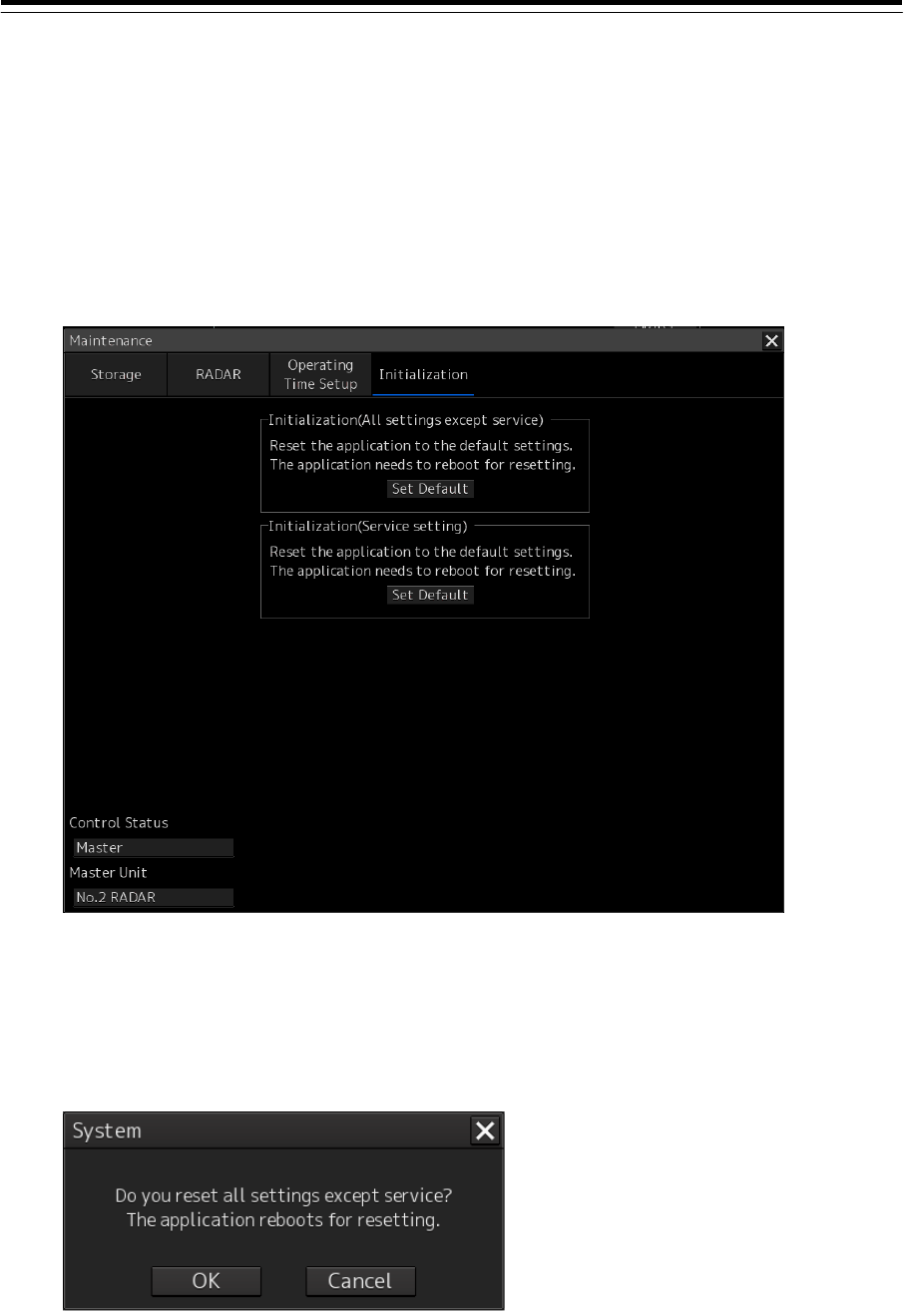
4-121
4.41 Initialization
[ALL]
The "Initialization" dialog can be used to return (initialize) the menu setting to the factory delivery state.
Displaying the "Initialization" dialog
1 Display the dialog of the Maintenance submenu.
2 Select [Initialization] in the classification pane.
The "Initialization" dialog is displayed in the Edit/Result pane.
Initializing the settings other than the Service menu
1 Click on [Set Default] (resetting to the default setting) of [Initialization (All settings
except service)].
The dialog prompting confirmation for execution of initialization is displayed.
2 To execute initialization, click on the [OK] button. To cancel initialization, click on the
[Cancel] or [x] button to close the dialog.
When the [OK] button is clicked on, the settings other than the Service menu are initialized and
the equipment restarts.
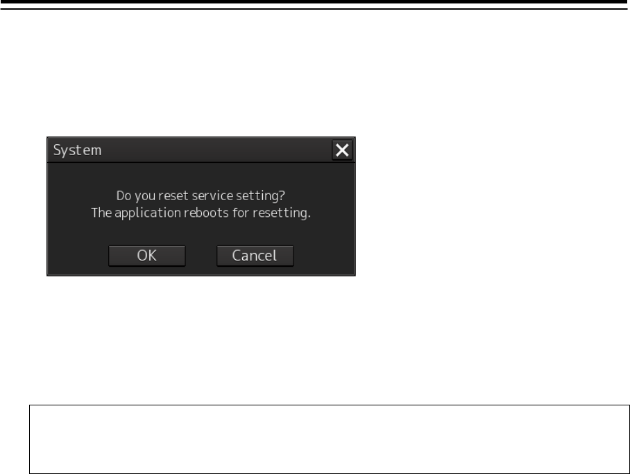
4-122
Initializing the setting of the Service menu
1 Click on the [Set Default] (reset to the default setting) button of [Initialization (Service
setting)].
The dialog for promoting confirmation for execution of initialization is displayed.
2 To execute initialization, click on the [OK] button. To cancel initialization, click on the
[Cancel] or [x] button to close the dialog.
When the [OK] button is clicked on, the setting of the Service menu is initialized and the
equipment restarts.
Memo
When the Control Status indicates Slave, the [Set Default] button of [Initialization (Service
setting)] can not be clicked on.
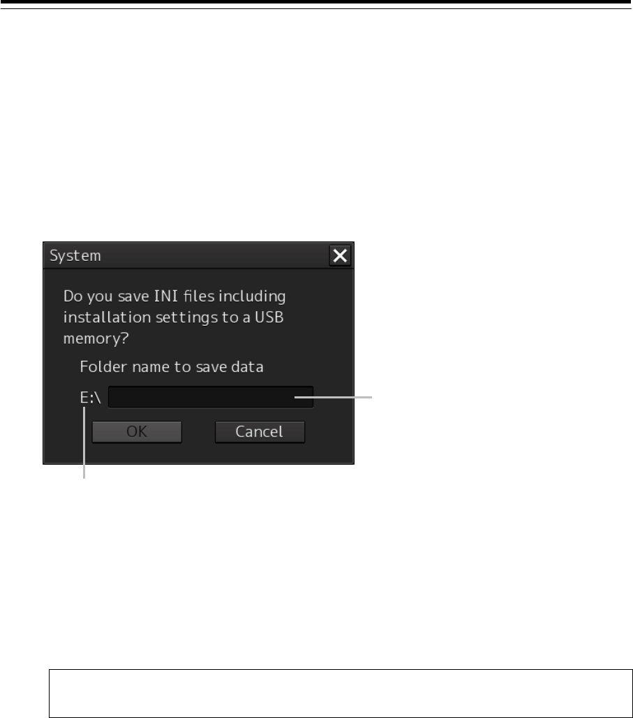
4-123
4.42 Backup of Data [ALL]
After completing installation, create a backup version (save) of the setting status in USB memory as
the "INI" folder.
Use the backup data that is created in the INI folder as the attached reference material of the
construction report.
Creating backup data
1 Enter 1111 in "Password" of the task menu.
The following dialog is displayed.
2 Click on the folder name input box.
A character input software keyboard is displayed.
3 Enter a name of the folder under which the INI folder is to be saved (up to 64
characters).
In a folder name input box, "unit number_YYYYMMDDHHMMSS" (UTC) is displayed in the
state of the first stage.
Note
Do not enter any blank space in the folder name.
4 Click on the [OK] button.
The folder under the name that is specified in Step 3 is created in the USB memory and the INI
folder is saved in that folder.
To cancel the backup operation of the INI folder, click on the [Cancel] button or the [X] button.
Case where the USB memory contains a folder of the same name
When the [OK] button is clicked on, a dialog is displayed prompting confirmation of overwriting the data.
Specify whether the data is to be overwritten or the operation is to be cancelled and another folder
name is to be specified.
The drive of the first USB memory that is detected is displayed.
Folder name input box

4-124
Case where backup cannot be executed
In any of the following cases, the [OK] button is disabled, thereby disabling backup operation.
The USB memory cannot be recognized.
A folder name has not been input in the folder name input box.
An invalid folder name (for example: containing blank space) is input in the folder name
input box.
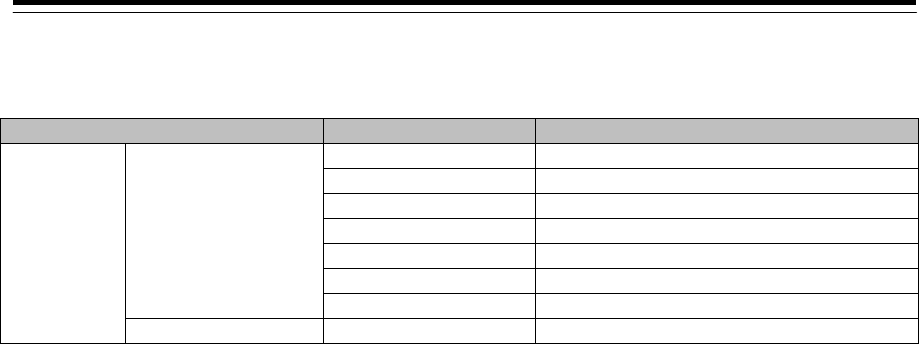
4-125
4.43 List of Common Setting Items [ALL]
Menu Item Remarks
Installation System Configuration Subsystem Installation Excluding Own Task Station.
CCRP
Serial Port Excluding Serial Port of CCU.
Contact Excluding Contact of CCU.
A/D
Network Excluding IP address setting of own task station
Redundancy
Ship’s Parameter Ship General

4-126
4.44 Password List
[ALL]
No. Dialog Password Action
1 Menu-Maintenance-System
Information-[Software] tab
0000 Displays the detailed software version for service
engineers.
2 Menu-Code input 9999 Returns to the task menu.
3 Menu-Code input 0 Displays the service menu for users.
4 Menu-Code input 0009 Displays the service menu for service engineers.
5 Task menu-Code Input 9380 Opens the license import dialog.
6 Task menu-Code Input 1111 Opens the dialog for backing up the INI folder.
7 Task menu-Code Input 0913 Start Internet Explorer.
8 Task menu-Code Input 5254 Update the ini file on the Conning screen. Open the folder
selection dialog and import the ini file in the folder and
update the file.