Japan Radio Co NKE2632 Solid State S-Band Marine Radar User Manual Instruction Manual Operation Part 4
Japan Radio Co Ltd. Solid State S-Band Marine Radar Instruction Manual Operation Part 4
Contents
- 1. Installation Manual Part 1
- 2. Installation Manual Part 2
- 3. Installation Manual Part 3
- 4. Installation Manual Part 4
- 5. Installation Manual Part 5
- 6. Installation Manual Part 6
- 7. Installation Manual Part 7
- 8. Installation Manual Part 8
- 9. Installation Manual Part 9
- 10. Installation Manual Part 10
- 11. Installation Manual Part 11
- 12. Instruction Manual Operation Part 1
- 13. Instruction Manual Operation Part 2
- 14. Instruction Manual Operation Part 3
- 15. Instruction Manual Operation Part 4
- 16. Instruction Manual Funtion Part 1
- 17. Instruction Manual Funtion Part 2
- 18. Instruction Manual Funtion Part 3
- 19. Instruction Manual Funtion Part 4
- 20. Instruction Manual Funtion Part 5
- 21. Instruction Manual Funtion Part 6
Instruction Manual Operation Part 4
Section 3 Common Basic Operations 3-38
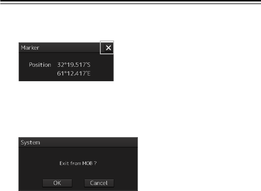
To exit from MOB
1 Click the [X] button in the Marker dialog box.
A confirmation dialog box appears.
2 Click on the [OK] button.
The "Marker" dialog is closed.
The MOB marker is cleared
3-39 Section 3 Common Basic Operations
1
2
3
4
5
6
7
8
9
10
11
12
13
14
15
16
17
18
19
20
21
22
23
24
25
APP A
APP B
1
3.11 Electronic Bearing Line (EBL) and
Variable Range Marker (VRM)
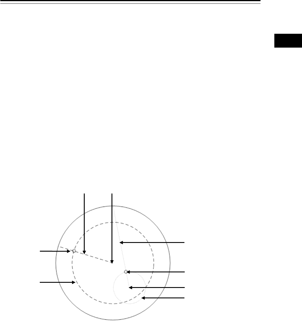
3.11.1 Electronic Bearing Line (EBL) and Variable
range marker (VRM)
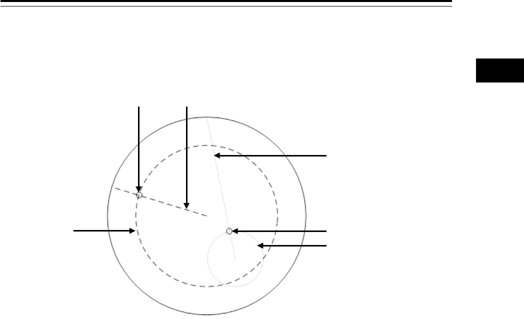
The electronic bearing line (EBL) and the variable range marker (VRM) are the essential tools for
measuring bearings and ranges.
This equipment is equipped with two sets each for EBL (EBL1/EBL2) and VRM (VRM1/VRM2).
An intersecting point mark is displayed at the intersecting point between EBL and VRM.
By setting an intersecting point at any location, the bearing and range from the own ship’s position to
the location can be measured.
Two sets of EBL and VRM can be operated independently.
The first EBL and VRM are displayed in Long dashed line and the second EBL and VRM are displayed
in Short dashed line.
Measurement
reference point
Measurement reference point
Intersection
mark
Intersection mark
EBL1
EBL2
VRM1
VRM2
Section 3 Common Basic Operations 3-40
Memo
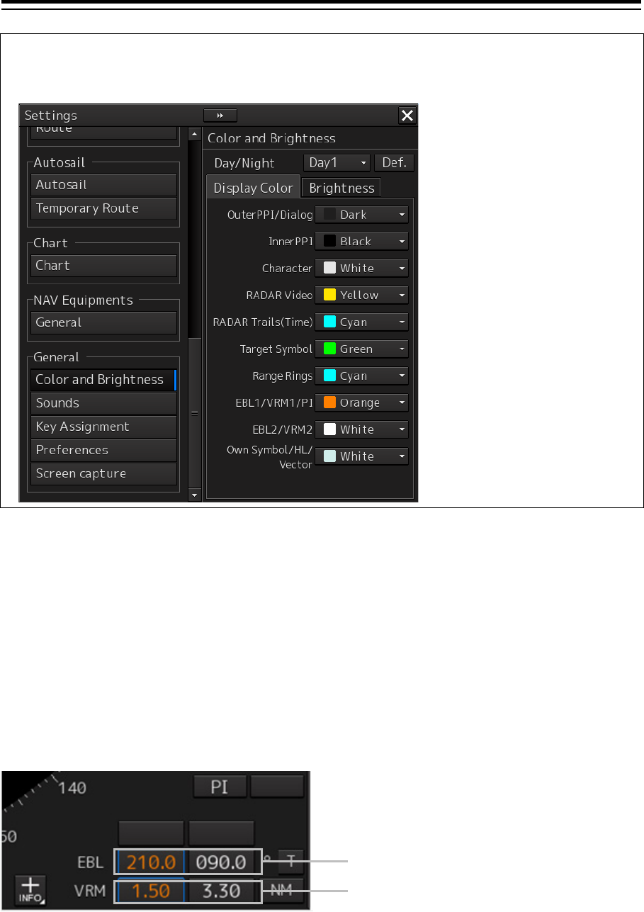
The line colors can be set on the dialog that is displayed by selecting [Settings] - [Color and
Brightness] on the menu.
3.11.2 Displaying the EBL and VRM buttons
Use the EBL/VRM button for creation and setting of EBL/VRM and bearing/range of EBL/VRM.
The display method varies between RADAR and ECDIS.
3.11.2.1 RADAR
For RADAR, the information is displayed on Navigation Tools (measuring tools) at the bottom right
corner of the screen.
EBL button (Left: EBL1, Right: EBL2)
VRM button (Left: VRM1, Right: VRM2)
3-41 Section 3 Common Basic Operations
1
2
3
4
5
6
7
8
9
10
11
12
13
14
15
16
17
18
19
20
21
22
23
24
25
APP A
APP B
1
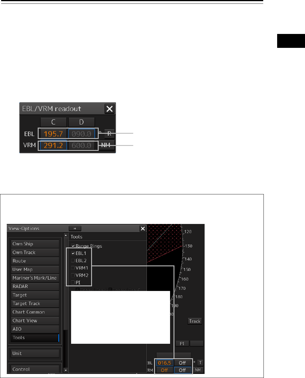
3.11.2.2 ECDIS
[Displaying from the menu]
Use the "EBL/VRM readout" dialog.
Use the following method to display the dialog.
1 Click on the [Menu] button on the left toolbar.
A menu is displayed.
2 Click on [Tools] - [EBL/VRM] on the menu.
The "EBL/VRM readout" dialog is displayed.
Closing the "EBL/VRM readout" dialog
Click on the [X] button.
Memo
The display mode of EBL/VRM that is displayed on the dialog by selecting [View] - [Options] -
[Tools] on the menu can be set to display/hide.
[Displaying by using the [EBL] and [VRM] dials]
By operating the [EBL] and [VRM] dials on the keyboard operation unit, the "EBL/VRM readout" dialog
can be displayed.
EBL button (Left: EBL1, Right: EBL2)
VRM button (Left: VRM1, Right: VRM2)
When this item is selected, the
information is displayed and when this
item is cleared, the information is
hidden.
The setting is linked to the button
display (for ECDIS, button display of the
"EBL/VRM readout" dialog).
Section 3 Common Basic Operations 3-42
3.11.3 Basic manipulation of EBL/VRM
3.11.3.1 Switching the control right of EBL/VRM
This equipment is equipped with two sets of EBL (EBL1/EBL2) and VRM (VRM1/VRM2).
To use EBL/VRM, the EBL/VRM to be used must be enabled.
To enable EBL/VRM, click on the EBL/VRM button.
The status of EBL/VRM can be checked by using the EBL/VRM button.
Memo
This explanation uses the case of RADAR and the manipulation procedure is also applicable to
ECDIS.
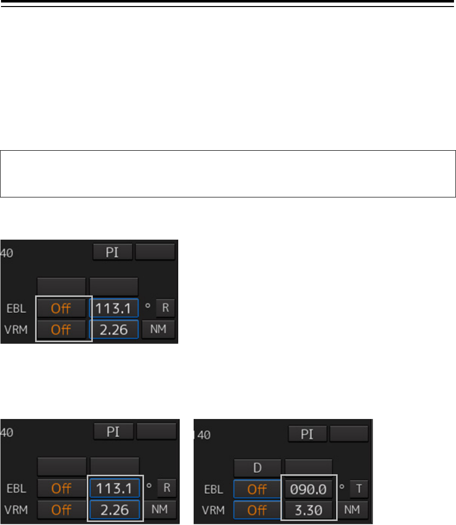
[Button in [OFF] state]
EBL/VRM is disabled and is not displayed on the screen.
When the button is clicked on, EBL/VRM is displayed and the manipulation is enabled.
[Numeric value displayed on the button]
• When the button is enclosed by a blue frame, EBL/VRM is displayed and the manipulation is
enabled (with control right).
When this button is clicked on, the blue frame is cleared and the manipulation is disabled (without
control right).
• When the button is not enclosed by a blue frame, although EBL/VRM is displayed on the screen,
the manipulation is disabled (without control right).
When the button is clicked on, the display is changed to [OFF].
When the button is double-clicked, the button is enclosed by a blue frame and the manipulation is
enabled (with control right).
3-43 Section 3 Common Basic Operations
1
2
3
4
5
6
7
8
9
10
11
12
13
14
15
16
17
18
19
20
21
22
23
24
25
APP A
APP B
1
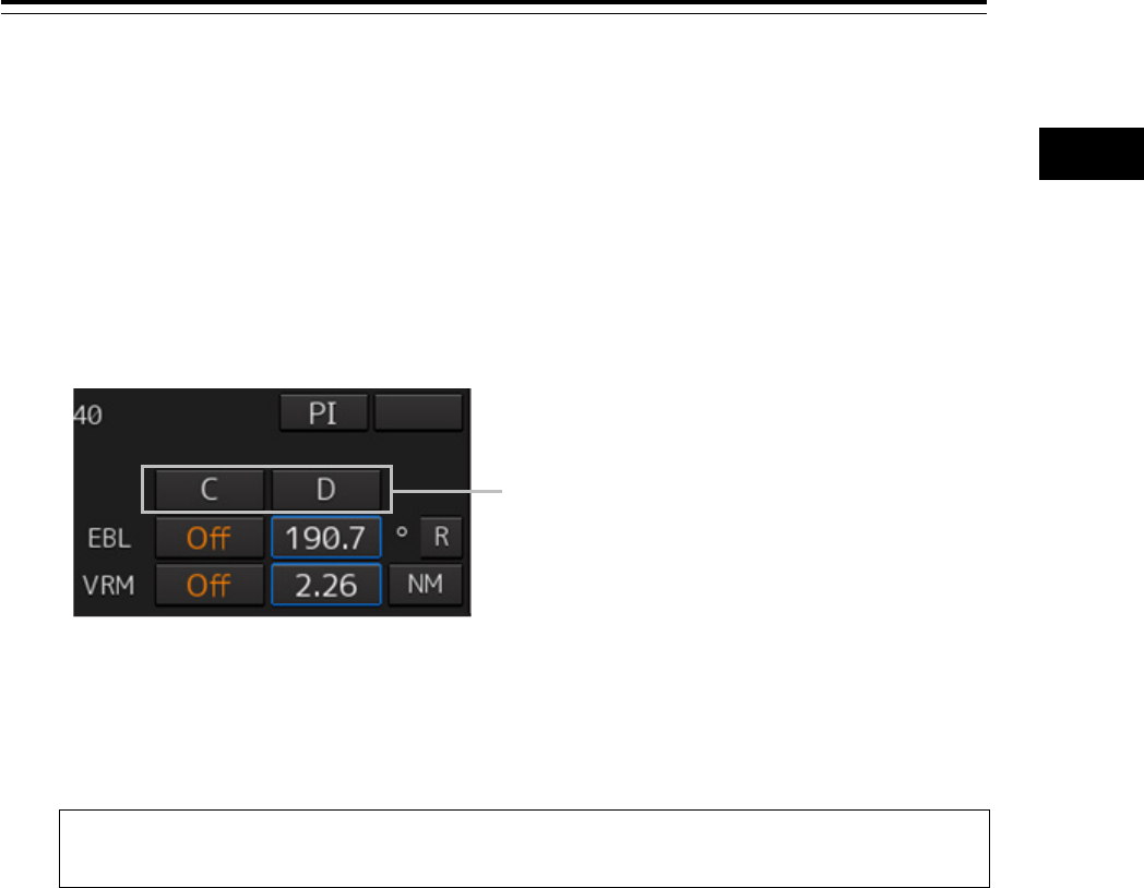
3.11.3.2 Setting up the measurement starting points
The measurement starting points of the EBL/VRM in operation can be changed. Set up the
measurement starting points as usage.
1 Enable the manipulation of EBL/VRM by clicking on the EBL/VRM button.
The display of the clicked button changes from [OFF] to the bearing presentation of the
measurement starting point.
2 Click on the Measurement Starting Point button of the EBL/VRM in the operational
state.
Each time this button is clicked on, the measurement starting point switches in the order of blank
field → [C] → [D] → blank field and so on.
Blank field (CCRP): Sets the measurement starting point to the own ship position (CCRP).
C (Carried): Fixes the measurement starting point on the screen.
D (Dropped): Fixes the measurement starting point at longitude and latitude point.
Memo
In the case of [D], it is necessary to connect a navigation unit.
Measurement starting point button
Section 3 Common Basic Operations 3-44
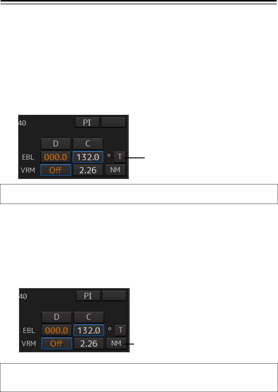
3.11.3.3 Setting the EBL bearing to True/Relative display
The EBL bearing True/Relative display can be changed by using the True/Relative button of EBL of the
Navigation Tools (measuring tools).
Setting the EBL numeric value display mode
1 Click on the true/relative button of EBL bearing.
Each time the button is clicked on, display switches between [T] → [R] → [T] in this order.
[T]: Displays EBL bearing in true bearing.
[R]: Displays EBL bearing in relative bearing.
Memo
The true/relative presentation of EBL bearing is common between EBL1 and EBL2.
3.11.3.4 Setting up the range unit of VRM
1 Click on the VRM Range Unit button.
Each time the button is clicked on, display switches in the order of [NM] → [sm] → [km] → [NM]
[NM]: Displays the range in the unit of NM.
[sm]: Displays the range in the unit of sm.
[km]: Displays the range in the unit of km.
Memo
The VRM range unit is common between VRM1 and VRM2.
NM denotes nautical mile, sm denotes statute mile, and km denotes kilometer.
True/relative button of EBL bearing
VRM range unit button
3-45 Section 3 Common Basic Operations
1
2
3
4
5
6
7
8
9
10
11
12
13
14
15
16
17
18
19
20
21
22
23
24
25
APP A
APP B
1
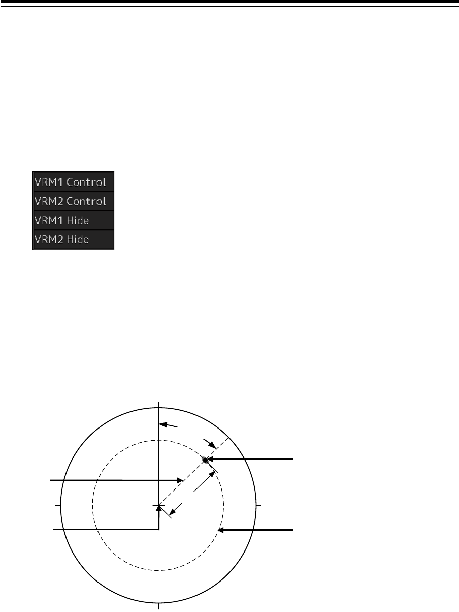
3.11.3.5 Operating the intersecting point between EBL and VRM
1 Place the cursor on the intersection mark (
) and click the mouse button.
EBL and VRM are set to a movable state.
2 Move the cursor to the required target or the coordinate.
EBL and VRM move together with the cursor.
3 Click on the mouse button.
The EBL and VRM are fixed.
Intersection mark
EBL1
EBL2
VRM2
VRM1
Intersection
mark

Section 3 Common Basic Operations 3-46
3.12 Cursor AUTO Mode
The cursor AUTO mode (referred to as AUTO mode henceforth) is a function that automatically
executes the function (operation) that is assigned to the object when the object under the cursor is
clicked on.
The AUTO mode is effective for the following objects.
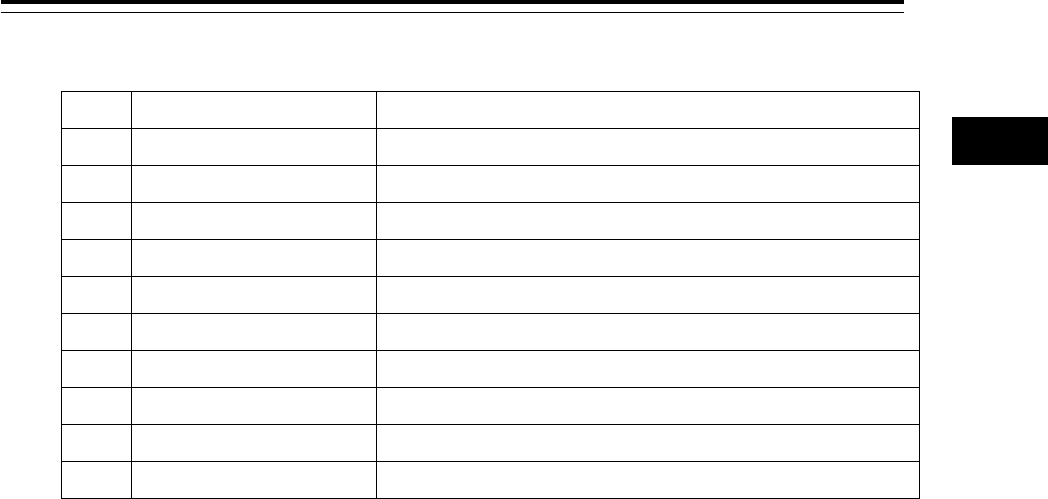
Object Section that describes the function
(operation) to be executed
No object (when the button is clicked on the position
without a valid object under the AUTO mode on a
chart/PPI)
3.12.1 No object
AIS 3.12.2 AIS
TT 3.12.3 TT
(AZ) Acquisition/Activation Zone 3.12.4 (AZ) Acquisition/Activation Zone
AIS filter 3.12.5 AIS filter
User map 3.12.6 User map
Mariner's Mark/Line 3.12.7 Mariner's Mark/Line
Manual update 3.12.8 Manual updating
Buoy object 3.12.9 Buoy object
Light object 3.12.10 Light object
EBL 3.12.11 EBL
VRM 3.12.12 VRM
EBL/VRM intersecting point 3.12.13 EBL/VRM intersecting point
Node Fixed EBL/VRM 3.12.14 Node Fixed EBL/VRM
PI 3.12.15 PI, 4.6 Using Parallel Index Lines (PI)
WPT of monitored route 3.12.16 WPT of monitored route
Monitoring dragging anchor 3.12.17 Monitoring dragging anchor
Route planning 3.12.18 Planned route
Note
When using ECDIS in AUTO mode, if there is no object under the cursor, the chart position at the
cursor will move to the center of the screen according to "3.12.1". When the ship is under vibration
and rough sea conditions, the center of the chart will be moved to an unintended position by
inadvertent left-click operation. Confirm the cursor type on the object is changed to other types
before left-click operation for AUTO mode operation.

3-47 Section 3 Common Basic Operations
1
2
3
4
5
6
7
8
9
10
11
12
13
14
15
16
17
18
19
20
21
22
23
24
25
APP A
APP B
1
3.12.1 No object
When the button is clicked on the position without a valid object under the AUTO mode on a chart/PPI,
the following operation is performed.
[ECDIS]
Executes off-centering (sets the clicked position as the center of the screen).
[RADAR]
Acquires the TT target manually when the button is clicked on inside of the PPI.
Note
Manual acquisition is not allowed in any of the following cases:
- Radar antenna standby state
- Occurrence of PROC (Interrupt 1) / PROC (Interrupt 2) alert
- Occurrence of target tracking function alert.
- Occurrence of ship's heading alert.
- Using at the position further than 32 NM from the own ship’s position
- Using at the position closer than 0.1 NM from the own ship’s position
3.12.2 AIS
[Sleeping AIS target target]
When a sleeping AIS target is clicked on, the AIS target is activated.
[Activated AIS target]
When an Activated AIS target is clicked on, the AIS target value is displayed.
[Numeric displayed AIS target]
When the numeric displayed AIS target is clicked on, the AIS target value display is cancelled.
[AIS-SAR aircraft normal target]
When an AIS-SAR aircraft in the normal state is clicked on, the AIS-SAR aircraft is selected and the
AIS-SAR aircraft value is displayed.
[Numeric displayed AIS-SAR aircraft]
When a numeric displayed AIS-SAR aircraft is clicked on, the sleeping target of the AIS-SAR aircraft is
displayed and the AIS-SAR aircraft value display is cancelled.
[Sleeping AIS-SAR vessel target]
The same operation as the normal sleeping AIS target is performed.

Section 3 Common Basic Operations 3-48
[Activated AIS-SAR vessel target]
The same operation as the normal activated AIS target is performed.
[Numeric displayed AIS-SAR vessel target]
The same operation as the normal numeric displayed AIS target is performed.
[Sleeping AIS-SART]
The same operation as the normal sleeping AIS target is performed.
[Activated AIS-SART]
The same operation as the normal activated AIS target is performed.
[Numeric displayed AIS-SART target]
The same operation as the normal numeric displayed AIS target is performed.
[AtoN normal target]
When AtoN target in a normal state is clicked on, the AtoN normal target is selected and the numeric
value of AtoN is displayed.
[Numeric displayed AtoN target]
When a numeric displayed AtoN target is clicked on, the AtoN normal target is deselected and the
numeric value of AtoN normal target is cancelled.
[AIS-shore base station normal target]
When an AIS-shore base station target in a normal state is clicked on, the AIS-shore base station is
selected and the numeric value of AIS-shore base station is displayed.
[Numeric displayed AIS-shore base station normal target]
When an AIS-shore base station in a normal state is clicked on, the AIS-shore base station is
deselected and the numeric value of AIS-shore base station is cancelled.
3.12.3 TT
[TT target]
When TT target is clicked on, a numeric value is displayed.
[Numeric displayed TT target]
When a numeric displayed TT target is clicked on, the numeric value display of TT is cancelled.
3-49 Section 3 Common Basic Operations
1
2
3
4
5
6
7
8
9
10
11
12
13
14
15
16
17
18
19
20
21
22
23
24
25
APP A
APP B
1
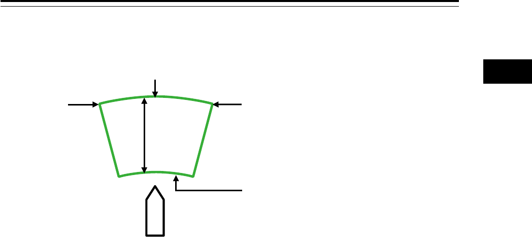
3.12.4 (AZ) Acquisition/Activation Zone
[Start Angle]
When Start Angle is clicked on, the cursor is set to the Start Angle/End Angle change mode.
[End Angle]
When End Angle is clicked on, the cursor is set to the End Angle change mode.
[Start Distance]
When Start Distance is clicked on, the cursor is set to the Start Distance/End Distance change mode.
[End Distance]
When End Distance is clicked on, the cursor is set to the End Distance change mode.
End Distance
Start Angle
End Angle
Own ship
Start Distance
Section 3 Common Basic Operations 3-50
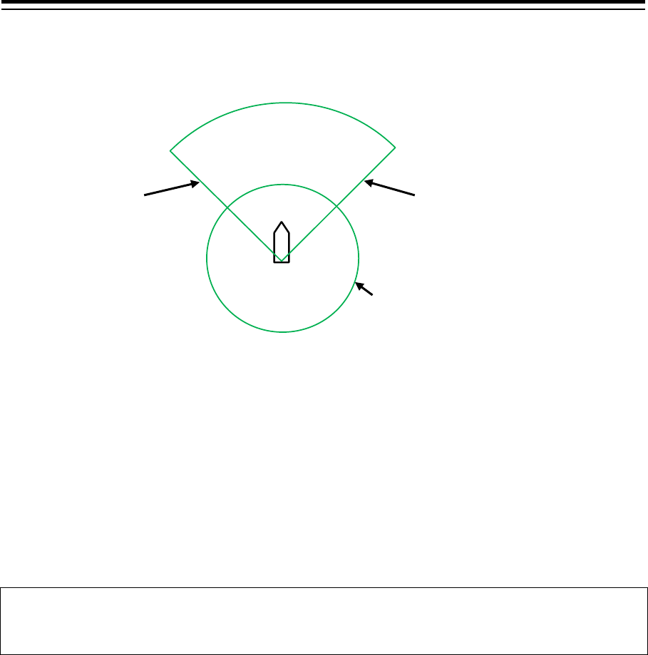
3.12.5 AIS filter
[Sector (start angle)]
When Sector (start angle) is clicked on, the cursor is set to the Sector (start/end angle) change mode.
[Sector (end angle)]
When Sector (end angle) is clicked on, the cursor is set to the Sector (end angle) change mode.
[Ring]
When Ring is clicked on, the cursor is set to the Ring change mode.
Memo
The values of Sector (start angle) and Sector (end angle) indicate relative bearings based on the
ship’s heading as the standard.
3.12.6 User map
The operation of an object in the unselected state is different from that of an object in the selected
state.
3.12.6.1 Non-selected object
When an object created on the user map is clicked on, the object is selected and the property screen of
the object is displayed.
Sector
(Start angle)
Ring
Own ship
Sector
(End angle)
* The section other than the
sides of the sector is not
targeted for selection.
3-51 Section 3 Common Basic Operations
1
2
3
4
5
6
7
8
9
10
11
12
13
14
15
16
17
18
19
20
21
22
23
24
25
APP A
APP B
1
3.12.6.2 Selected object
The operation varies according to the object.
(1) Symbol
When the selected symbol is clicked on, a symbol move mode is set.
When the right button is clicked, the symbol move mode is cancelled.
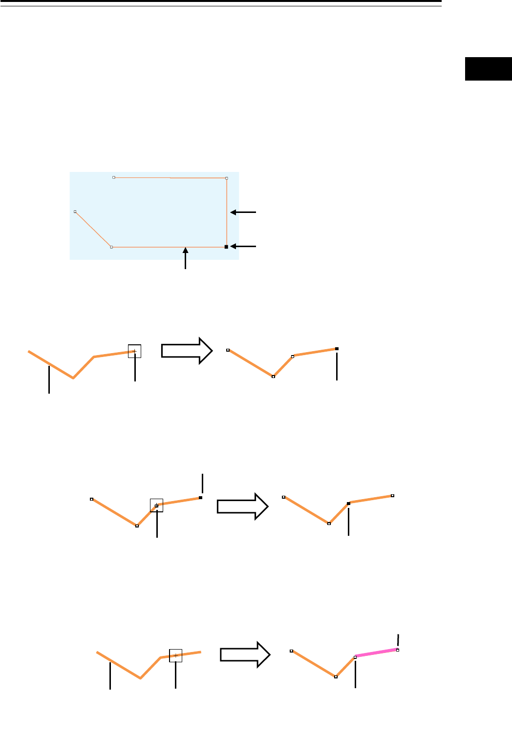
(2) Simple line
[Selecting vertex]
<Non-selected state>
<Selected state>
[Selecting a line segment]
Simple line in the non-selected state
Vertex
Simple line in the selected
state
SEL
Non-selection state
Click
The vertex is selected and the
simple line property screen is
displayed.
SEL
Click
The vertex on which the button was
clicked is selected and the simple line
property screen is displayed.
Vertex in the selected state
SEL
Click
Non-selection state
Corresponding vertex
Line segment selected state. The
property screen of the corresponding
vertex is displayed.

Section 3 Common Basic Operations 3-52
[Moving a vertex]
When the middle point of simple line in the selected state is clicked on, vertex move mode of simple
line is set.
[Inserting a vertex]
When a line segment of simple line in the selected state is clicked on, vertex insertion mode of simple
line is set.
Memo
A vertex can also be inserted by using [Insert Vertex] on the context menu that is displayed by
clicking the right button on the simple line in the selected state.
When the insertion point is the starting point or the ending point, a vertex can be inserted with [Add
Vertex].
[Cancelling operation]
By clicking the right button, the vertex addition, move, or insertion mode can be cancelled.
(3) Line-Circle
[Moving Line-Circle]
When the circumference of the line-circle in the selected state is clicked on, move mode of line-circle
is set.
[Chainging a radius]
When a square of four corners of the line-circle in the selected state is clicked on, radius set mode of
line-circle is set.
[Cancelling operation]
By clicking the right button, the line-circle move or radius change mode can be cancelled.
(4) Line-Ellipse
[Moving line-ellipse]
When the circumference of the line-ellipse in the selected state is clicked on, move mode of
line-ellipse is set.
[Changing vertical/horizontal width]
When a square of four corners of the line-ellipse in the selected state is clicked on, a
vertical/horizontal width change of line-ellipse mode is set.
[Cancelling operation]
By clicking the right button, the line-ellipse move or vertical/horizontal width change mode can be
cancelled.
3-53 Section 3 Common Basic Operations
1
2
3
4
5
6
7
8
9
10
11
12
13
14
15
16
17
18
19
20
21
22
23
24
25
APP A
APP B
1
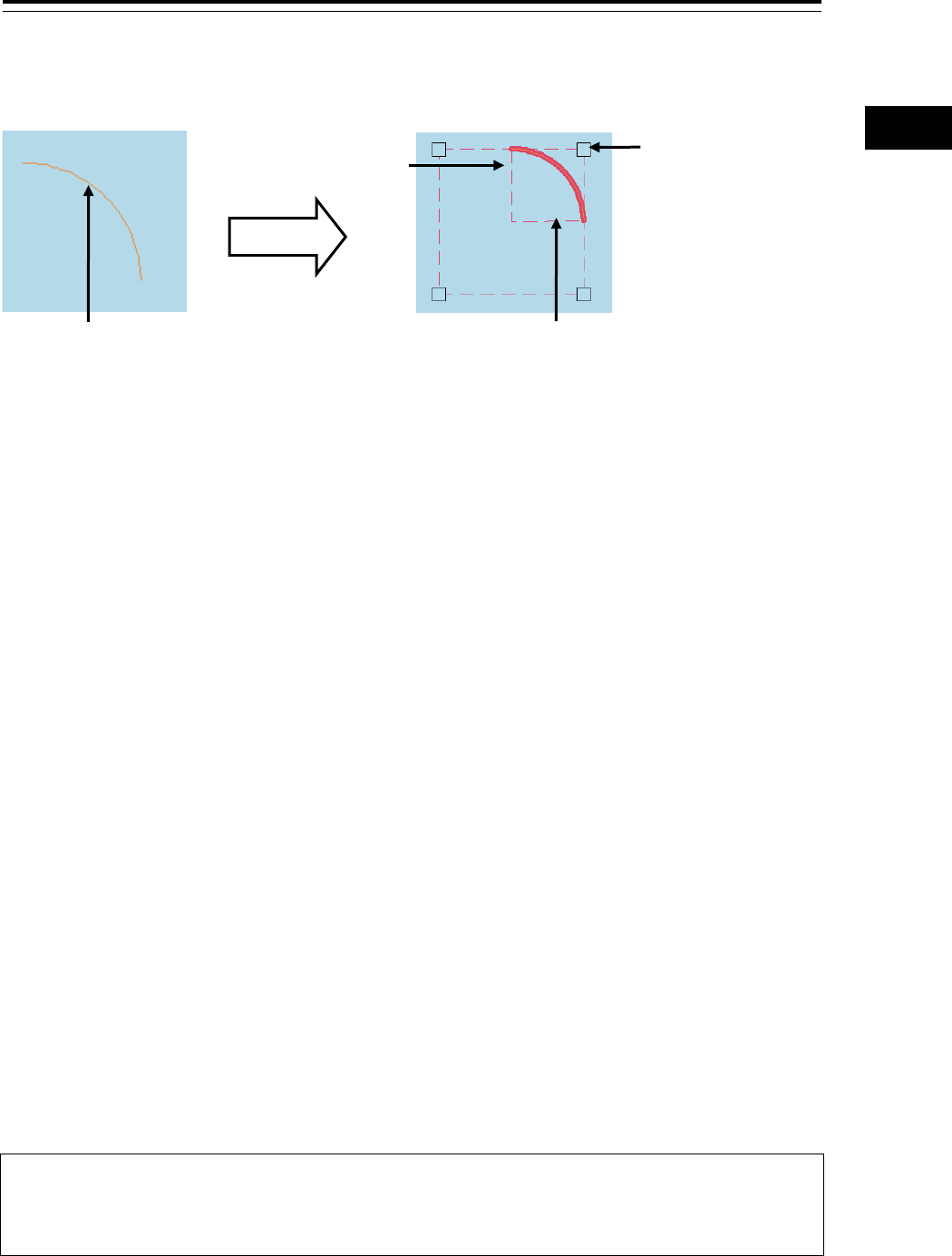
(5) Arc
[Moving an arc]
When the arc in the selected state is clicked on, move mode of arc is set.
[Changing a radius]
When a square of four corners of the arc in the selected state is clicked on, radius set mode of arc is
set.
[Drawing start angle]
When a drawing start angle of the arc in the selected state is clicked on, drawing start angle set mode
of arc is set.
[Drawing end angle]
When a drawing end angle of the arc in the selected state is clicked on, drawing end angle set mode
of arc is set.
[Cancelling operation]
By clicking the right button, the arc move, radius change, drawing start angle change, or drawing end
angle change mode can be cancelled.
(6) Polygon
[Moving a vertex]
When a vertex of the polygon in the selected state is clicked on, vertex move mode of polygon is set.
[Inserting a vertex]
When a line segment of the polygon in the selected state is clicked on, vertex insertion mode of
polygon is set.
Memo
A vertex can also be inserted by using [Insert vertex] on the context menu that is displayed by
clicking the right button on the selected polygon.
[Moving a polygon]
When the inside of the polygon in the selected state is clicked on, move mode of polygon is set.
A square of
four corners
Drawing start
Drawing end angle
Arc
Click

Section 3 Common Basic Operations 3-54
[Cancelling operation]
By clicking the right button, the vertex move, insertion, or polygon move mode can be cancelled.
(7) Area-Circle
[Moving Area-Circle]
When the radius of the area-circle in the selected state is clicked on, an area-circle move mode is set.
[Changing a radius]
When a square formed by four corners of area-circle in the selected state is clicked on, an area-circle
radius setting mode is set.
[Cancelling operation]
By clicking the right button, the area-circle move or radius change mode can be cancelled.
(8) Area-Ellipse
[Moving area-ellipse]
When the radius or inside of the area-ellipse in the selected state is clicked on, an area-ellipse move
mode is set.
[Changing a radius]
When a square formed by four corners of area-ellipse in the selected state is clicked on, an
area-ellipse radius setting mode is set.
[Cancelling operation]
By clicking the right button, the area-ellipse move or radius change mode can be cancelled.
(9) Sector
[Moving a sector]
When a circumference or inside of the sector in the selected state is clicked on, a fan move mode is
set.
[Changing a radius]
When a square formed by four corners of the sector in the selected state is clicked on, a sector radius
setting mode is set.
[Drawing start angle]
When a drawing start angle of the sector in the selected state is clicked on, a sector drawing start
angle setting mode is set.
[Drawing end angle]
When a sector drawing end angle in the selected state is clicked on, a sector drawing end angle
setting mode is set.

3-55 Section 3 Common Basic Operations
1
2
3
4
5
6
7
8
9
10
11
12
13
14
15
16
17
18
19
20
21
22
23
24
25
APP A
APP B
1
[Cancelling operation]
By clicking on the right button, the sector move, radius change, drawing start angle change or
drawing end angle change mode can be cancelled.
(10) Text
[Moving text]
When the text object in the selected state is clicked on, move mode of the text object is set.
[Cancelling operation]
By clicking the right button, the text move mode can be cancelled.
(11) Arrow
[Moving an arrow]
When a line segment of the arrow in the selected state is clicked on, move mode of the arrow is set.
[Moving a start point]
When a start point of the arrow in the selected state is clicked on, start point move mode of the arrow
is set.
[Moving an end point]
When an end point of the arrow in the selected state is clicked on, end point move mode of the arrow
is set.
[Cancelling operation]
By clicking the right button, the arrow move or start point/end point move mode can be cancelled.
3.12.7 Mariner's Mark/Line
3.12.7.1 Object in the non-selected state
When the object that is created by using Mariner's Mark/Line is clicked on, the object is selected and
the property screen of the object is displayed.
3.12.7.2 Object in selected state
The operation varies according to the object.
(1) Event mark in the selected state
When an event mark is clicked on, the selected state of the event mark is cleared.
(2) Information Mark
When Information Mark in the selected state is clicked on, move mode of Information Mark is set.
By clicking the right button, the Information Mark move mode can be cancelled.
i

Section 3 Common Basic Operations 3-56
(3) Tidal Stream
When Tidal Stream in the selected state is clicked on, move mode of Tidal Stream is set.
By clicking the right button, the Tidal Stream move mode can be cancelled.
(4) Clearing Line
[Moving Clearing Line]
When a line segment of Clearing Line in the selected state is clicked on, move mode of Clearing Line
is set.
[Moving a start point]
When a start point of Clearing Line in the selected state is clicked on, start point move mode of
Clearing Line is set.
[Moving an end point]
When an end point of Clearing Line in the selected state is clicked on, end point move mode of
Clearing Line is set.
[Cancelling operation]
By clicking the right button, the Clearing Line move or start point/end point move mode can be
cancelled.
(5) Highlight
[Moving a vertex]
When a vertex of a highlight in the selected state is clicked on, vertex move mode of highlight is set.
[Inserting a vertex]
When a line segment of a highlight in the selected state is clicked on, vertex insertion mode of
highlight is set.
Memo
A vertex can also be inserted by using [Insert vertex] on the context menu that is displayed by
clicking the right button on a highlight in the selected state.
[Moving a highlight]
When an inside of a highlight in the selected state is clicked on, entire shift mode of highlight is set.
[Cancelling operation]
By clicking the right button, the vertex move, insertion, or highlight move mode can be cancelled.
(6) Plotted Position
[Moving a Plotted position]
When Plotted position in the selected state is clicked on, a Plotted position mode move is set.
[Cancelling operation]
By clicking the right button, the Plotted position move mode can be cancelled.

3-57 Section 3 Common Basic Operations
1
2
3
4
5
6
7
8
9
10
11
12
13
14
15
16
17
18
19
20
21
22
23
24
25
APP A
APP B
1
3.12.8 Manual updating
3.12.8.1 Unsaved object
The operation of AUTO mode of unsaved objects is the same as for the user map.
3.12.8.2 Saved object
When setting an edit mode by clicking on the saved object, the property screen of the saved object is
displayed.
3.12.9 Buoy object
When a buoy object is clicked on, a pick cursor is displayed at the clicked point and the [Chart Info]
dialog box is displayed.
Memo
The pick cursor indicates a square frame that is displayed at the point from which the chart
information was read and the chart object information inside of the frame is displayed in the "Chart
Information" dialog.
3.12.10 Light object
When a light object is clicked on, a pick cursor is displayed at the selected point and the [Chart Info]
dialog box is displayed.
Memo
The pick cursor indicates a square frame that is displayed at the point from which the chart
information was read and the chart object information inside of the frame is displayed in the "Chart
Information" dialog.
3.12.11 EBL
When EBL is clicked, the mode becomes one in which EBL is operated alone.
3.12.12 VRM
When VRM is clicked, the mode becomes one in which VRM is operated alone.

Section 3 Common Basic Operations 3-58
3.12.13 EBL/VRM intersecting point
When the EBL/VRM intersection point is clicked, the mode becomes one in which EBL and VRM are
operated simultaneously.
3.12.14 Node Fixed EBL/VRM
When Node Fixed EBL/VRM is clicked on, the clicked point becomes the EBL/VRM intersecting point,
and an EBL/VRM (1step) drawing mode is set. (The start point follows the own ship’s position.)
3.12.15 PI
Four PI setting modes are available and the operation of the cursor AUTO mode varies depending
on the setting.
For the details, refer to "4.6 Using Parallel Index Line (PI)".
3.12.16 WPT of monitored route
When a WPT of a monitored route is clicked on, the detail information of the WPT is displayed.
3.12.17 Monitoring dragging anchor
3.12.17.1 Object in the unselected state
When a monitoring dragging anchor object is clicked on, the clicked object is set to the selected state
and the "Anchor Watch" dialog box is displayed.
3.12.17.2 Selected state
Dragging anchor monitoring circle
[Moving a dragging anchor monitoring circle]
When a circumference of a dragging anchor monitoring circle in the selected state is clicked on,
move mode of dragging anchor monitoring circle is set.
[Changing a radius]
When a square of the four corners of a dragging anchor monitoring circle in the selected state is
clicked on, radius setting mode of dragging anchor monitoring circle is set.
[Cancelling operation]
By clicking the right button, the dragging anchor monitoring circle move or radius change mode can
be cancelled.
3-59 Section 3 Common Basic Operations
1
2
3
4
5
6
7
8
9
10
11
12
13
14
15
16
17
18
19
20
21
22
23
24
25
APP A
APP B
1
Dragging anchor monitoring polygon
[Moving a polygon]
When a vertex of a dragging anchor monitoring polygon in the selected state is clicked on, a vertex
move mode of dragging anchor monitoring polygon is set.
[Inserting a vertex]
When a line segment of a dragging anchor monitoring polygon in the selected state is clicked on, a
vertex insertion mode of dragging anchor polygon is set.
Memo
A vertex can also be inserted by using [Insert vertex] on the context menu that is displayed by
clicking the right button on a dragging anchor monitoring polygon in the selected state.
[Moving a polygon]
When an inside of the dragging anchor monitoring polygon in the selected state is clicked on, a total
shift mode of dragging anchor monitoring polygon is set.
[Cancelling operation]
By clicking the right button, the vertex move, insertion or dragging anchor monitoring polygon move
mode can be cancelled.
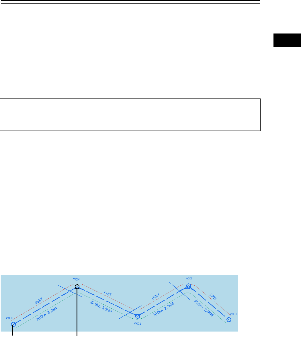
3.12.18 Planned route
[WPT]
When WPT in the unselected state is clicked on, WPT is in the selected state and WPT edition mode is
set.
By clicking on the right button, the WPT move mode can be cancelled.
Unselected state
Selected state
Section 3 Common Basic Operations 3-60
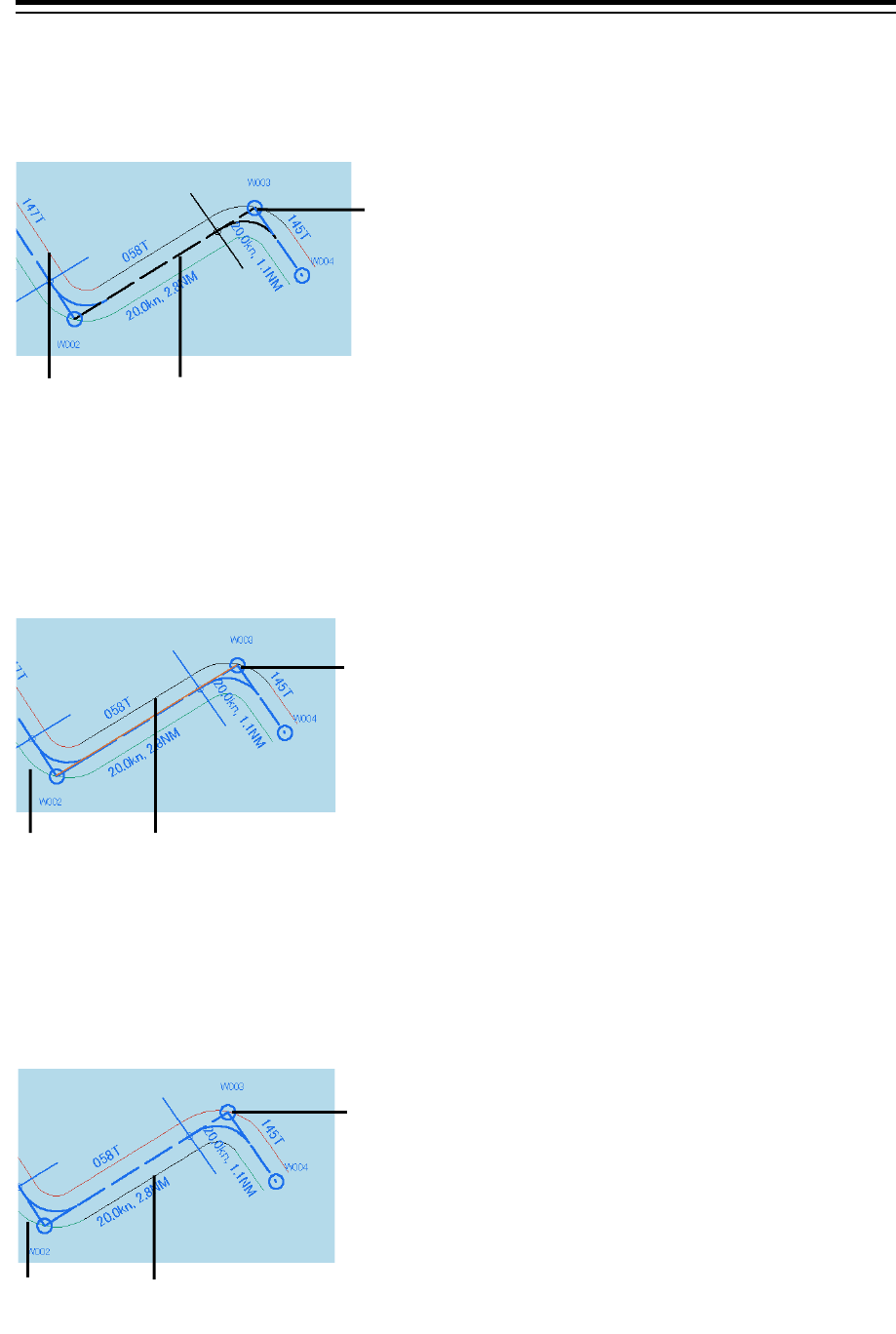
[Leg]
When Leg in the unselected state is clicked on, WPT is in the selected state and WPT insert mode is
set.
By clicking the right button, the WPT insertion mode can be cancelled.
[PORT]
When PORT in the unselected state is clicked on, PORT is in the selected state and PORT width
change mode is set.
By clicking the right button, the PORT width change mode can be cancelled.
[STBD]
When STBD in the unselected state is clicked on, STBD is in the selected state and STBD width
change mode is set.
By clicking the right button, the STBD width change mode can be cancelled.
Unselected
state
Selected state
WPT corresponding
to the selected Leg
Unselected
state
WPT corresponding
to the selected PORT
Selected state
Unselected
state
WPT corresponding
to the selected STBD
Selected state
3-61 Section 3 Common Basic Operations
1
2
3
4
5
6
7
8
9
10
11
12
13
14
15
16
17
18
19
20
21
22
23
24
25
APP A
APP B
1
3.13 Saving the screen that is currently
displayed
The image that is displayed on the screen can be saved as a PNG file.
Use the following procedure to save screen images.
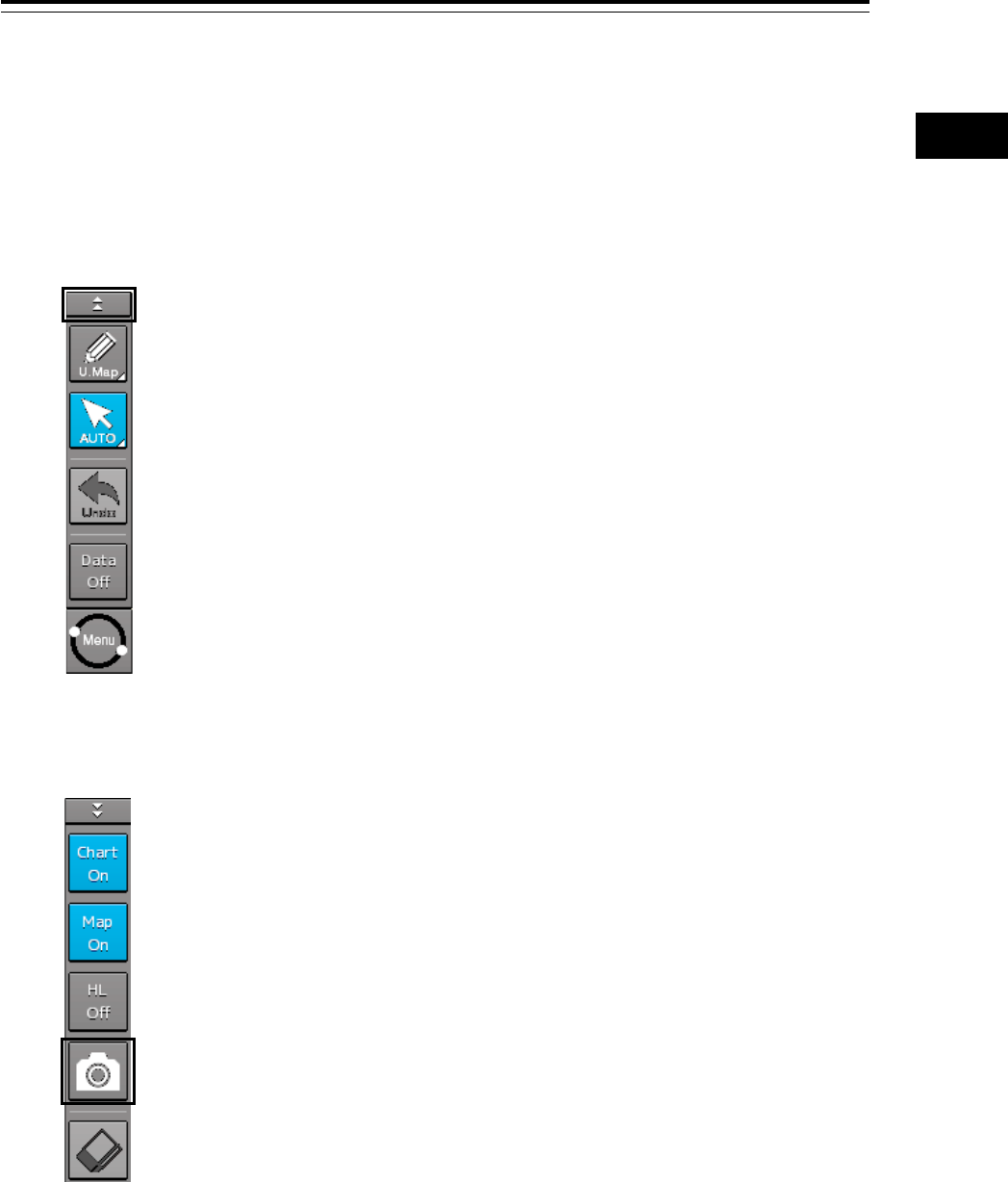
1 Click on the Disclosure button on the left toolbar.
Buttons normally hidden are displayed.
2 Click on the screen capture button.
The screen that is currently displayed is saved and the next confirmation dialog box is
displayed.
When the screen contents cannot be saved:
When the screen contents cannot be saved due to insufficient disk free space, an error dialog is
displayed.
In this case, secure sufficient disk free space and save the contents again.
Section 3 Common Basic Operations 3-62
3.14 [MULTI] Dial
3.14.1 Functions of [MULTI] dial
By turning the [MULTI] dial, the functions that are assigned to the [MULTI] dial can be operated.
Assignment to the [MULTI] dial can be changed.
3.14.2 Functions assigned to [MULTI] dial
3.14.2.1 Displaying a screen for setting the function that is
assigned
By pressing the [MULTI] dial, the setting screen for the function that is currently assigned can be
displayed.
3.14.2.2 Changing the function that is assigned
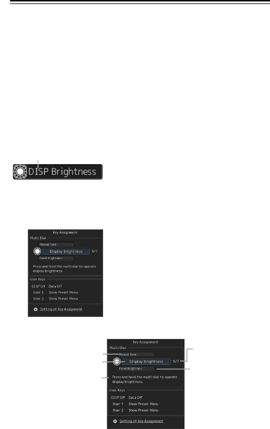
1 Press the [MULTI] dial.
The "Key Assignment" dialog box of the assigned function is displayed.
2 Select a function to be assigned from [Multi Dial] by turning the [MULTI] dial.
Assigned function name
Sequence number of
assigned function and the
total number
Another function available for selection
Another function available
for selection
Item on the blue button is the function that
is currently selected
Description of the function that is
currently selected
3-63 Section 3 Common Basic Operations
1
2
3
4
5
6
7
8
9
10
11
12
13
14
15
16
17
18
19
20
21
22
23
24
25
APP A
APP B
1
The table below lists the functions that can be assigned.
No. Function name Function outline
1 Vector Time Selection of a vector length
2 Trails Length Selection of a radar trail length
3 C UP Angle Change of the course-up angle
4 Own Track Color Selection of an own track color
5 Manual Tune Manual tuning
6 Display Brightness Adjustment of brightness of the display panel
7 Panel Brightness Adjustment of brightness of the operation panel
8 Gain Adjustment of sensitivity
9 Sea Removal of sea clutter
10 Rain Removal of rain and snow clutter
*For the RADAR screen, functions 1 to 10 can be used. For the ECDIS screen, functions other
than functions 2 and 5 can be used.
3 Press the [MULTI] dial.
The selected function is set to the assigned function.
Section 3 Common Basic Operations 3-64
3.15 Basic Operations of the Software
Keyboard
Use a software keyboard for inputting numeric values and characters in various setting operations.
This section describes the basic operations of a software keyboard.
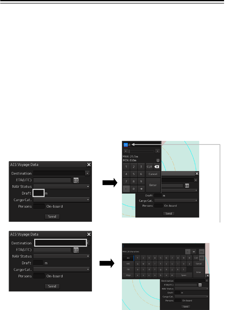
3.15.1 Starting a software keyboard
When the mouse button is clicked on a numeric input text box on such as a dialog box, a numeric input
software keyboard is displayed.
When the mouse button is clicked on a character input text box, a character input full keyboard is
displayed.
The mouse cursor moves to the
inside of the software
keyboard.
3-65 Section 3 Common Basic Operations
1
2
3
4
5
6
7
8
9
10
11
12
13
14
15
16
17
18
19
20
21
22
23
24
25
APP A
APP B
1
3.15.2 Name and function of each section of the
keyboard
Numeric value input software keyboard
Sowtware full keyboard for character input
* The description of the functions common to those of a numeric value input software keyboard is omitted.
[1]
[2]
[2]
[3]
[4]
[5]
[7]
[8]
[9]
[12]
[6]
[10]
[11]
[18]
[17]
[13]
[14]
[15]
[16]
Section 3 Common Basic Operations 3-66
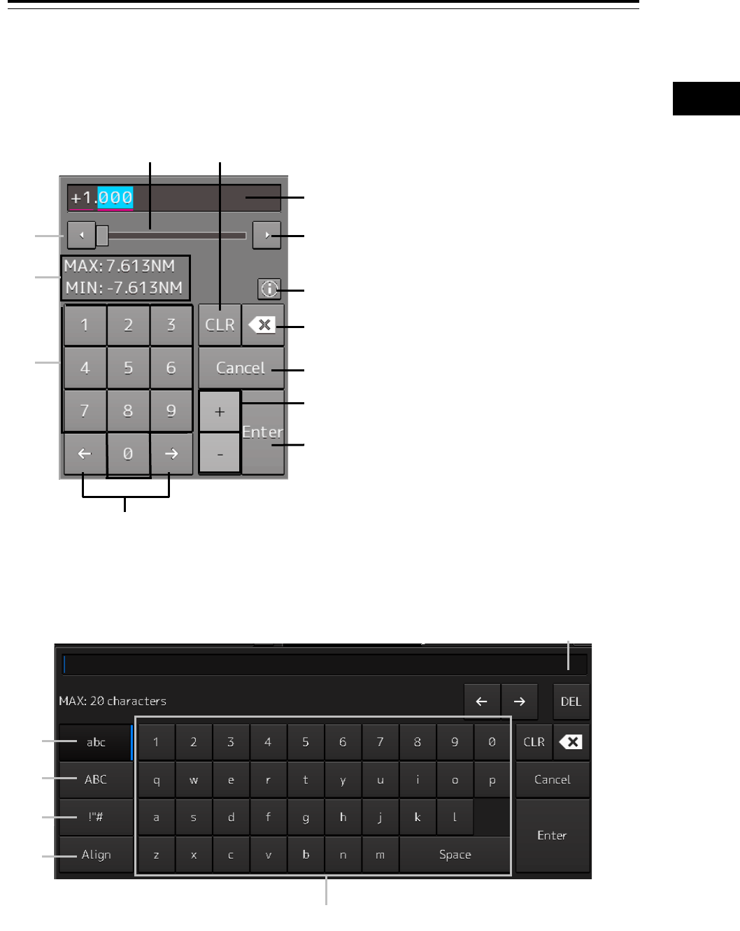
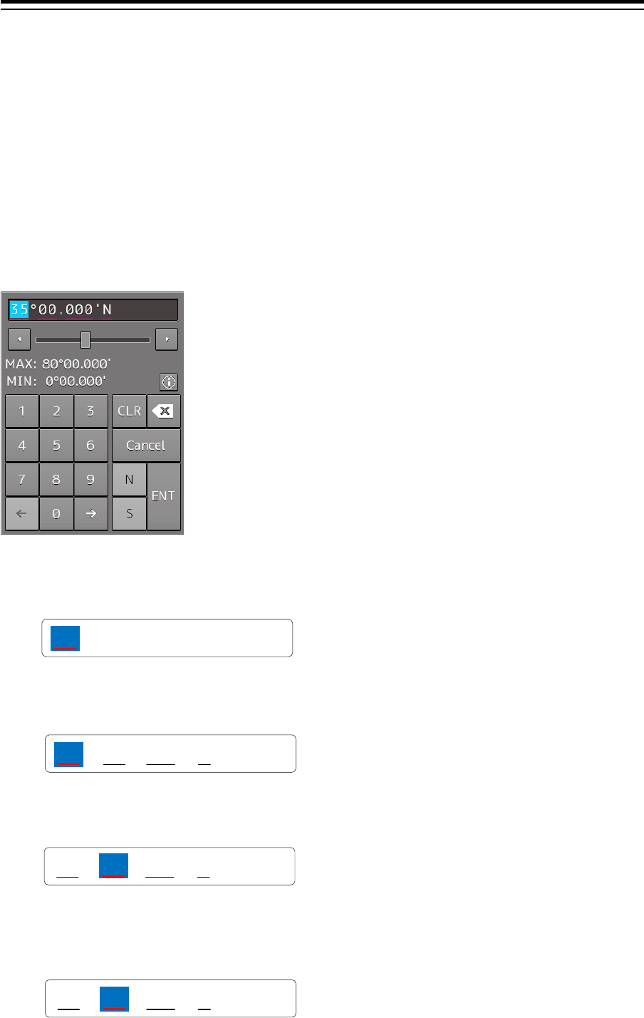
[1] Input value display section
Displays the value that is input/edited through the software keyboard.
[2] Spin button
• When the right spin button is clicked on, the minimum unit value that can be set is added to the
value that is displayed. When the left spin button is clicked on, the minimum unit value that can be
set is subtracted from the value that is displayed.
Example of addition
• When the mouse button is held down on the right spin button, the value is added consecutively.
When the mouse button is held down on the left spin button, the value is subtracted consecutively.
• When the value set by the right spin button operation exceeds the maximum value, the minimum
value is set subsequently. When the value set by the left spin button operation becomes lower than
the minimum value, the maximum value is set subsequently.
[3] Numeric value slider
When the value adjustment button on the value slider is clicked on, the input value increases or
decreases.
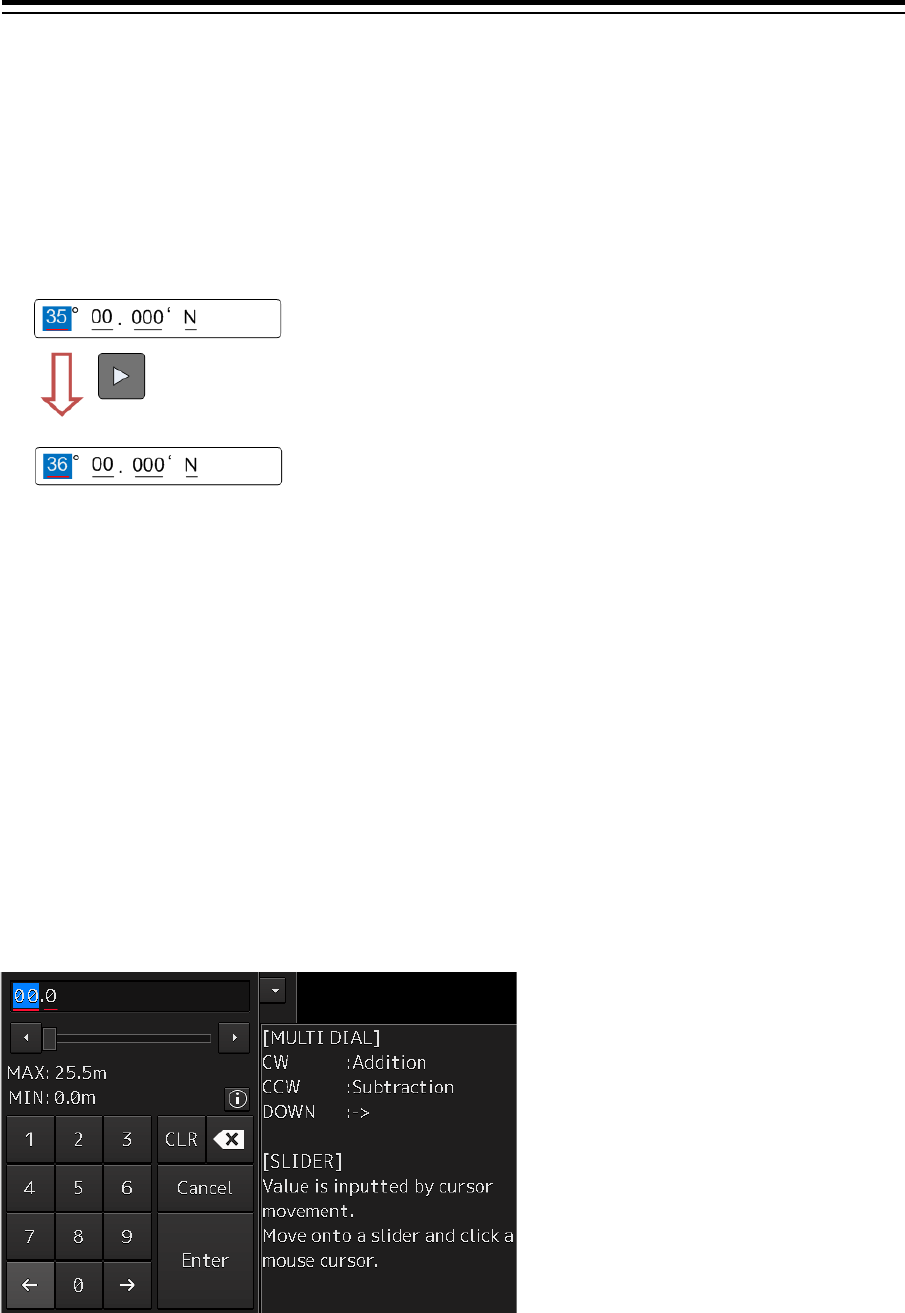
[4] Operation guide display button
Displays an operation guide.
To close the operation guide, click on the operation guide display button again or click on a location
other than the operation guide.
[5] [CLR] key
Clears the input value that is currently selected.
3-67 Section 3 Common Basic Operations
1
2
3
4
5
6
7
8
9
10
11
12
13
14
15
16
17
18
19
20
21
22
23
24
25
APP A
APP B
1
[6] Back Space key
Clears the input value on the left-side of the cursor position.
[7] [Cancel] key
Cancels the input operation and closes the software keyboard.
[8] Option key
Displays the following keys according to the type of the software keyboard.
• Signed keyboard: + key and - key
• Latitude software keyboard: Direction key [N key and S key)
• Longitude software keyboard: Direction key [E key and W key)
[9] [Enter] key
Determines the input operation.
[10] Input range display section [format display section)
Displays the values and character types that can be input.
[11] Numeric keys
Use the keys for input of numeric values.
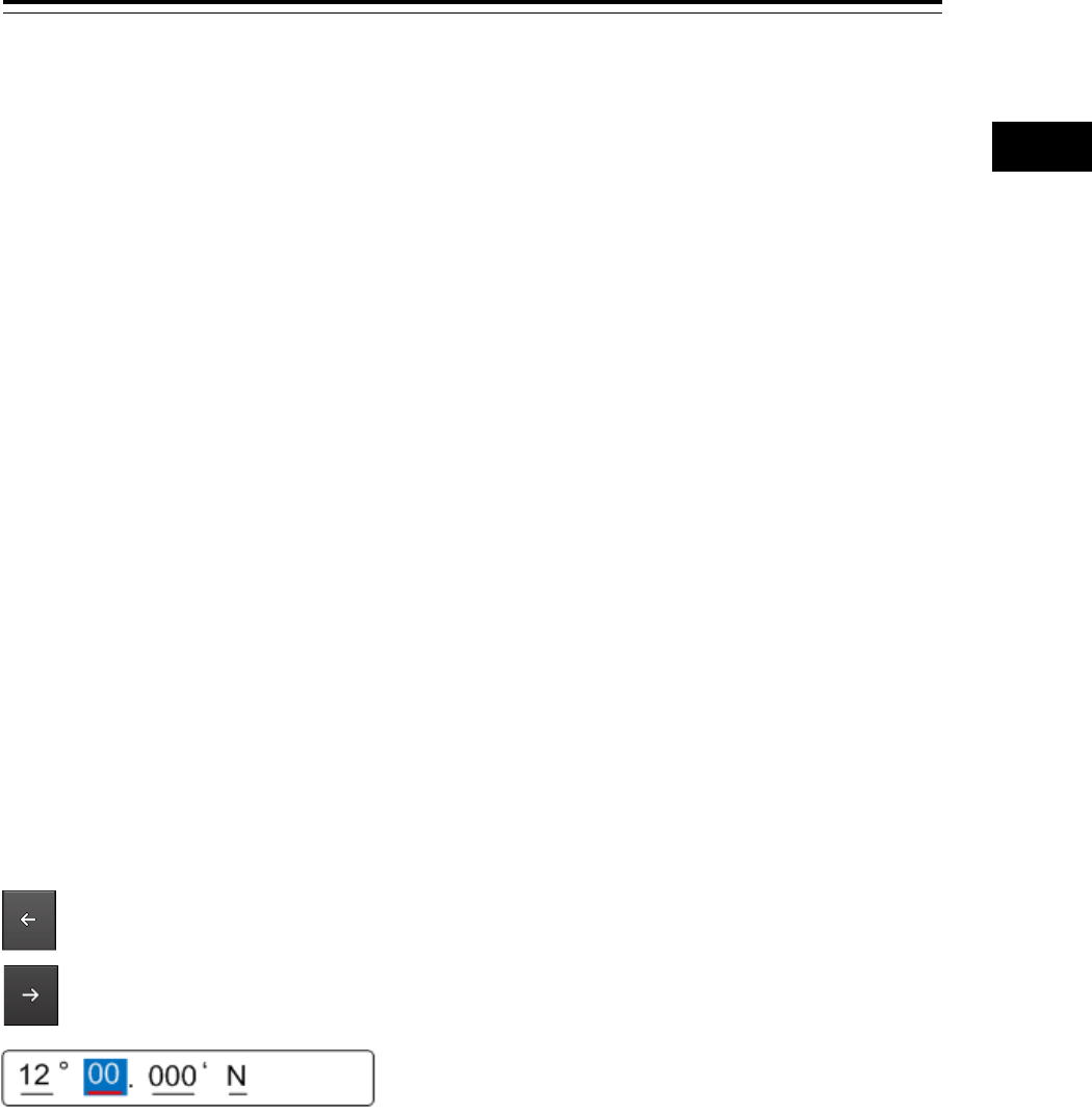
[12] Arrow keys
When there are multiple input parts, the active part can be moved to the left/right by clicking on the
arrow key.
Example:
When the (left arrow key) is clicked on, the input section moves to "12".
When the (right arrow key) is clicked on, the input section moves to "000".
[13] Lowercase character switching key
Changes the character input key mode to the lowercase character mode.
[14] Uppercase character switching key
Changes the character input key mode to the uppercase character mode.
[15] Symbol switching key
Changes the character input key mode to the symbol mode.
[16] Key alignment switching key
Switches the character key alignment between QWERTY alignment and alphabetic alignment.
Section 3 Common Basic Operations 3-68
[17] Character input key
Use this key for character input.
[18] [DEL] key
Deletes the character on the right-side of the cursor.
3.15.3 Numeric value input example
In this example, "12°34.567’ S" (south latitude 12°34.567’) is input as the latitude.
1 Start up the latitude software keyboard.
2 Enter "1".
3 Enter "2".
The active part moves to the right by one position.
4 Enter "3".
00 .
35 °000 ‘N
00 .
1°000 ‘N
.
12 °000 ‘N
00
.
12 °000 ‘N
3
3-69 Section 3 Common Basic Operations
1
2
3
4
5
6
7
8
9
10
11
12
13
14
15
16
17
18
19
20
21
22
23
24
25
APP A
APP B
1
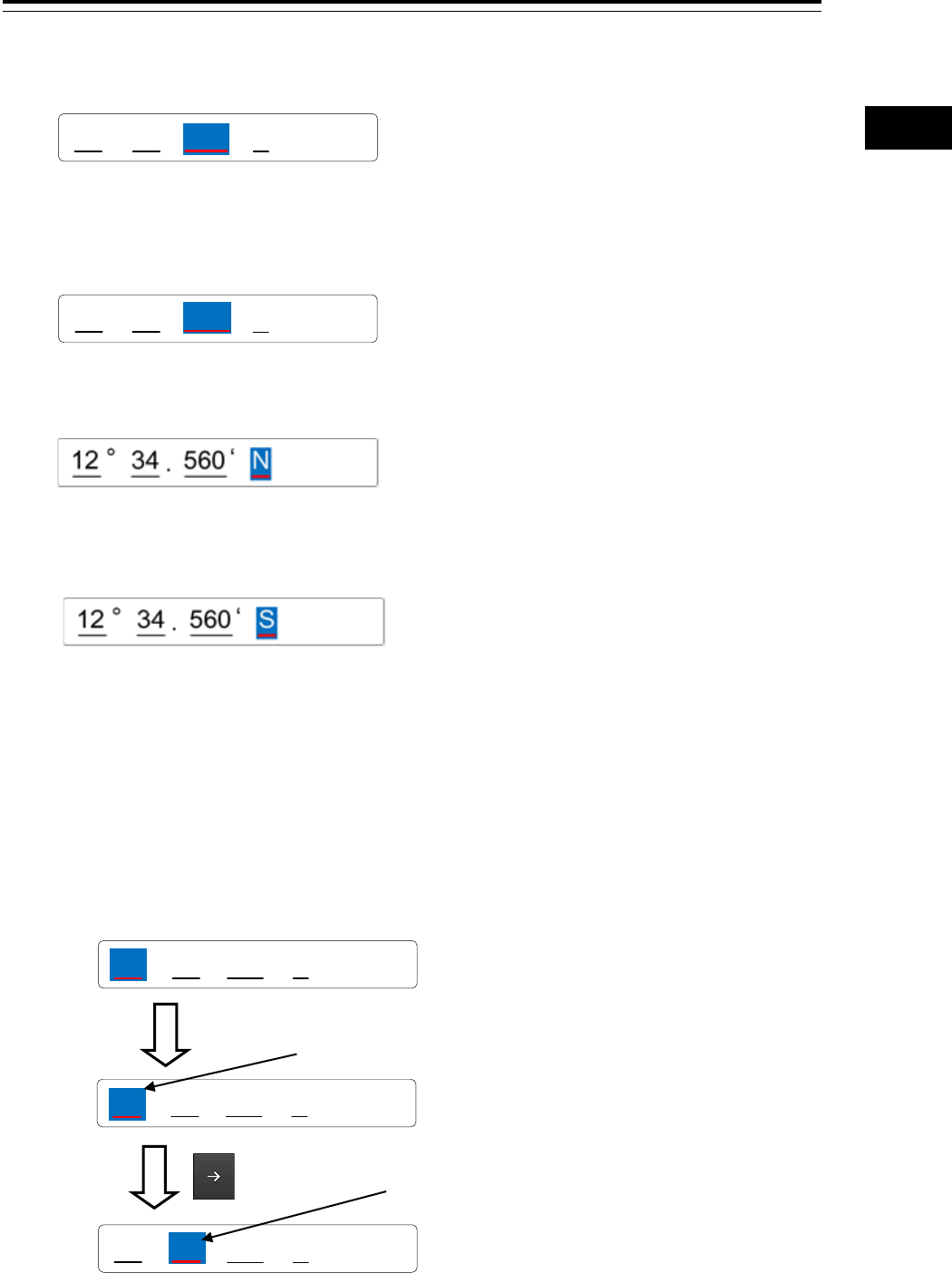
5 Enter "4".
The active part moves to the right by one position.
6 Enter "5" and "6".
7 Set the active part by clicking on the input part ("N" in this example) at the right end.
8 Click on the [S] key of the option key.
"N" changes to "S".
9 When the right arrow key is clicked, input is determined and the software keyboard is
closed.
Inputting a single-digit value
Enter a value and click on another input part or move the active part by using the right arrow key.
.
12 ° ‘ N
34 000
.
35 °56 ‘N
00
12
12 °34
Example:
Enter 1.
The value that is input by clicking on another input part or
the right arrow key becomes a single-digit value and the
value is determined. 0 is input in the blank space.
00 .
35 °000 ‘N
00 .
1°000 ‘N
.
01 °000 ‘N
00
Section 3 Common Basic Operations 3-70
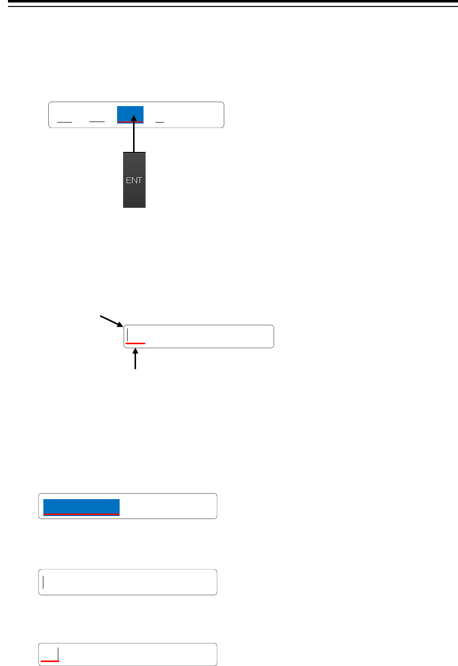
Inputting blank space in the decimal fraction section (3 digits)
After a value is input and the [Enter] key is clicked on, the input of the decimal fraction section is
determined.
3.15.4 Character input example
This section describes character input by using a full keyboard.
Input example
1 Start up a full keyboard.
When a value [character) has been input in the text box, the full character string is selected at
startup.
2 Delete the character string by clicking the Back Space key.
3 Input any character string.
4 Determine the input by clicking on the [Enter] key.
Enter "5" and click on the [Enter] key.
A "0" is displayed in the blank column
next to "5", and the numerical value
gets confirmed.
.
35 °5‘N
00
Example:
aaaaaaaaaa
ab
ab
Input caret
Indicates the
character input
position.
Active mark
Indicates the character string that is being input.
3-71 Section 3 Common Basic Operations
1
2
3
4
5
6
7
8
9
10
11
12
13
14
15
16
17
18
19
20
21
22
23
24
25
APP A
APP B
1
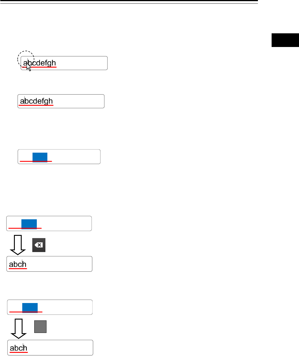
Character modification example
1 Move the cursor to the left-end (or right-end) of the character string to be modified and
click the mouse button.
The input caret moves to the clicked position.
2 Click the mouse button on the input caret position and select the character string to be
modified by dragging with the trackball.
* When the character string is selected, the input caret is cleared.
3 Perform the following operation in the selected state.
[Deleting a selected section]
[Replacing a selected section]
abcdefgh
abcdefgh
When the Back Space key is clicked on,
the selected section is deleted.
abcdefgh
Input any character in the selected state.
(In this example, "i" is input.)
i
Section 3 Common Basic Operations 3-72
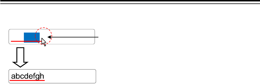
[Canceling a selected state]
4 After modification is determined, determine the input by clicking on the [Enter] key.
abcdefgh
Under a selected state, click on another section inside of
the active mark to cancel the selection. The input caret
moves to the clicked position.
3-73 Section 3 Common Basic Operations
1
2
3
4
5
6
7
8
9
10
11
12
13
14
15
16
17
18
19
20
21
22
23
24
25
APP A
APP B
1
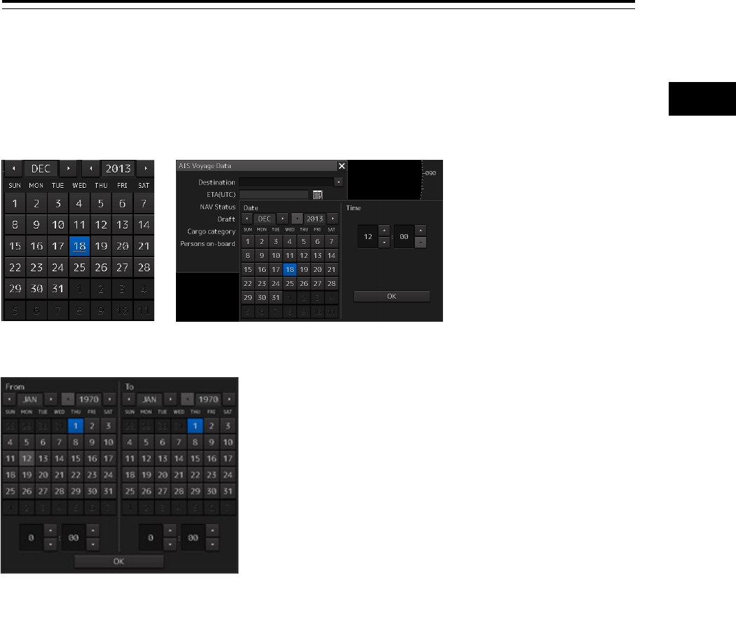
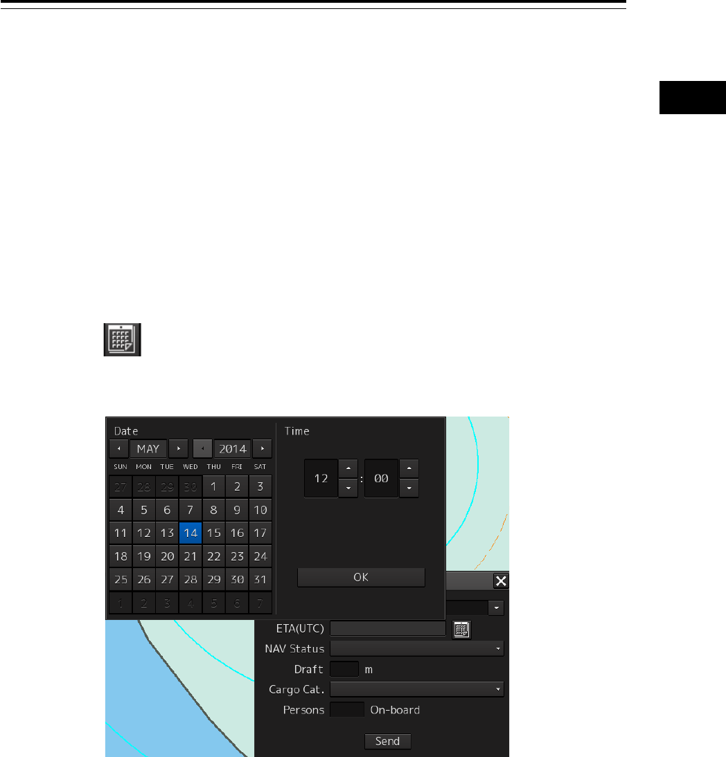
3.16 Setting a Date and a Time (Calendar
Operation)
Set a date and a time on the calendar input screen.
The following calendar types are available.
Calendar picker Calendar picker + Time picker
From-To calendar picker
+ Time picker
Section 3 Common Basic Operations 3-74
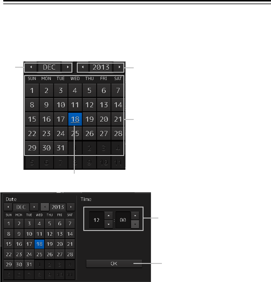
3.16.1 Details and usage of a calendar picker and a
time picker
3.16.1.1 Details of a calendar
[1] Year selection spin button
Selects a year to be displayed in the date selection box.
• When the right spin button is clicked on, the year is changed in the ascending order.
• When the left spin button is clicked on, the year is changed in the descending order.
[2] Month selection spin button
Selects a month to be displayed in the date selection box.
• When the right spin button is clicked on, the month is changed in the ascending order.
• When the left spin button is clicked on, the month is changed in the descending order.
[3] Day selection box
Selects a day.
[1]
[3]
Selected date
[5]
[4]
[2]
3-75 Section 3 Common Basic Operations
1
2
3
4
5
6
7
8
9
10
11
12
13
14
15
16
17
18
19
20
21
22
23
24
25
APP A
APP B
1
[4] Time selection spin button
Sets an hour, a minute, and a second.
• When the upper spin button is clicked on, the hour, minute, and second are changed in the
ascending order.
• When the lower spin button is clicked on, the hour, minute, and second are changed in the
descending order.
[5] [OK] button
Completes the setting and closes the calendar.
3.16.1.2 How to use a calendar
1 Click on (calendar) button next to the date setting box.
A calendar is displayed.
2 Set a year and a month by using the year selection spin button and the month
selection spin button respectively.
3 Click on the day to be set from the day selection box.
* In the case of a calendar picker only, the day is set at this stage and the calendar picker is
closed.
4 Set a time by clicking on the time spin button of the time picker.
5 Click on the [OK] button.
The setting is completed and the calendar is closed.
Section 3 Common Basic Operations 3-76
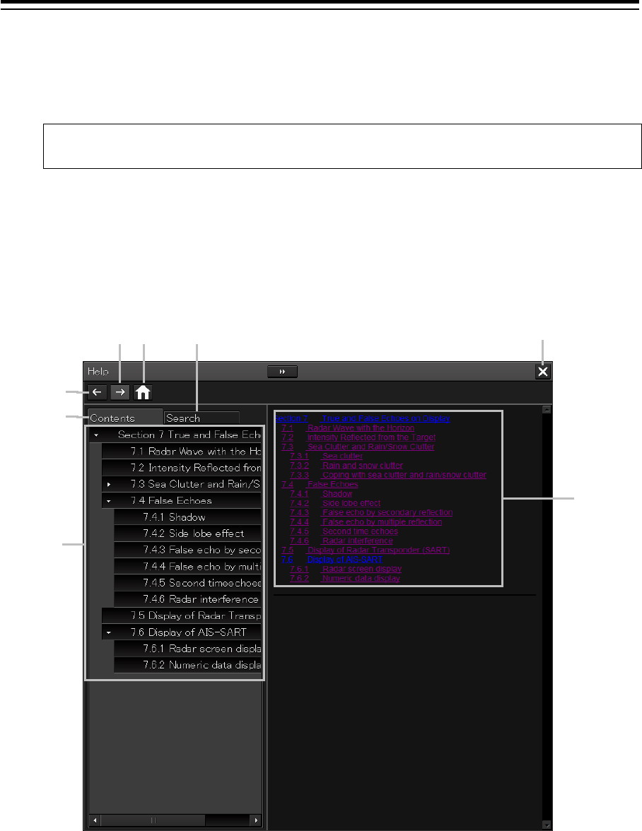
3.17 Help
Help information on the operation of this equipment can be displayed.
Memo
The Preface, Section 1 and Appendix A are not displayed in the Help.
1 Click on the [Menu] button on the left toolbar.
The menu is displayed.
2 Click on the [Help] button on the menu.
The [Help] dialog box appears.
[1] Backward button
The display of the content display pane goes backwards by one.
[2] Forward button
The display of the content display pane goes forwards by one.
[5]
[6]
[1]
[7]
[8]
[2]
[3]
[4]

3-77 Section 3 Common Basic Operations
1
2
3
4
5
6
7
8
9
10
11
12
13
14
15
16
17
18
19
20
21
22
23
24
25
APP A
APP B
1
[3] [Contents] tab
Displays the contents. The contents are displayed in the content pane.
For the procedure, refer to "Searching the required information from the contents"
[4] Content pane
The contents are displayed in tree format. When an item is clicked on, the related
contents are displayed in the content display pane.
[5] Home button
Displays the home screen of the "Help" dialog box.
[6] [Search] tab
Searches the character string in Help.
For the procedure, refer to "Searching terminologies ".
[7] Content display pane
Displays the contents of the item that was clicked on.
[8] [×] button.
Closes the "Help" dialog box.
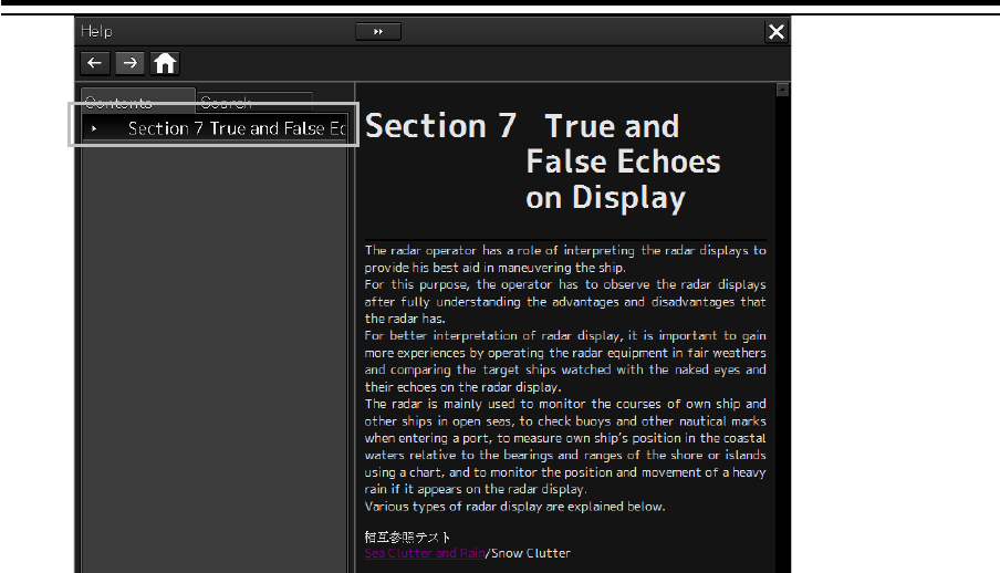
Searching the required information from the contents.
1 Click on the [Contents] tab.
The contents are displayed on the contents pane.
2 Click on the item containing the required information.
The contents of the item that was clicked on are displayed on the contents display pane.
Section 3 Common Basic Operations 3-78
3-79 Section 3 Common Basic Operations
1
2
3
4
5
6
7
8
9
10
11
12
13
14
15
16
17
18
19
20
21
22
23
24
25
APP A
APP B
1
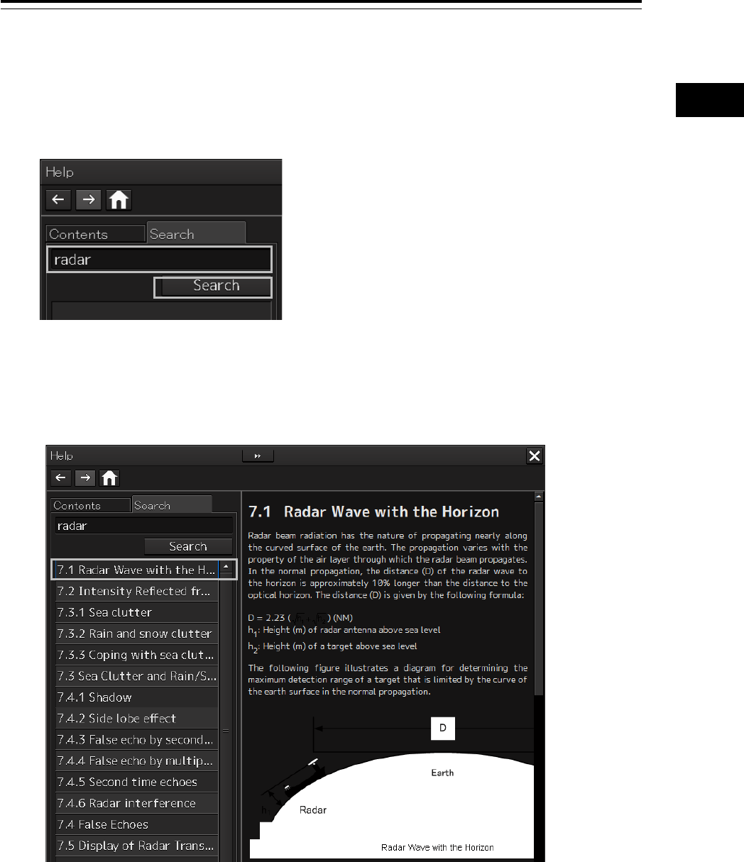
Searching terminologies
1 Click on the [Search] tab.
A search character input box is displayed.
2 Enter a required terminology and click on the [Search] button.
Search is performed within Help. When the applicable terminology is hit, the item containing the
terminology is displayed on the contents pane.
3 Click on the item containing the required information.
The contents of the item that is clicked on are displayed on the contents display pane.
Section 3 Common Basic Operations 3-80
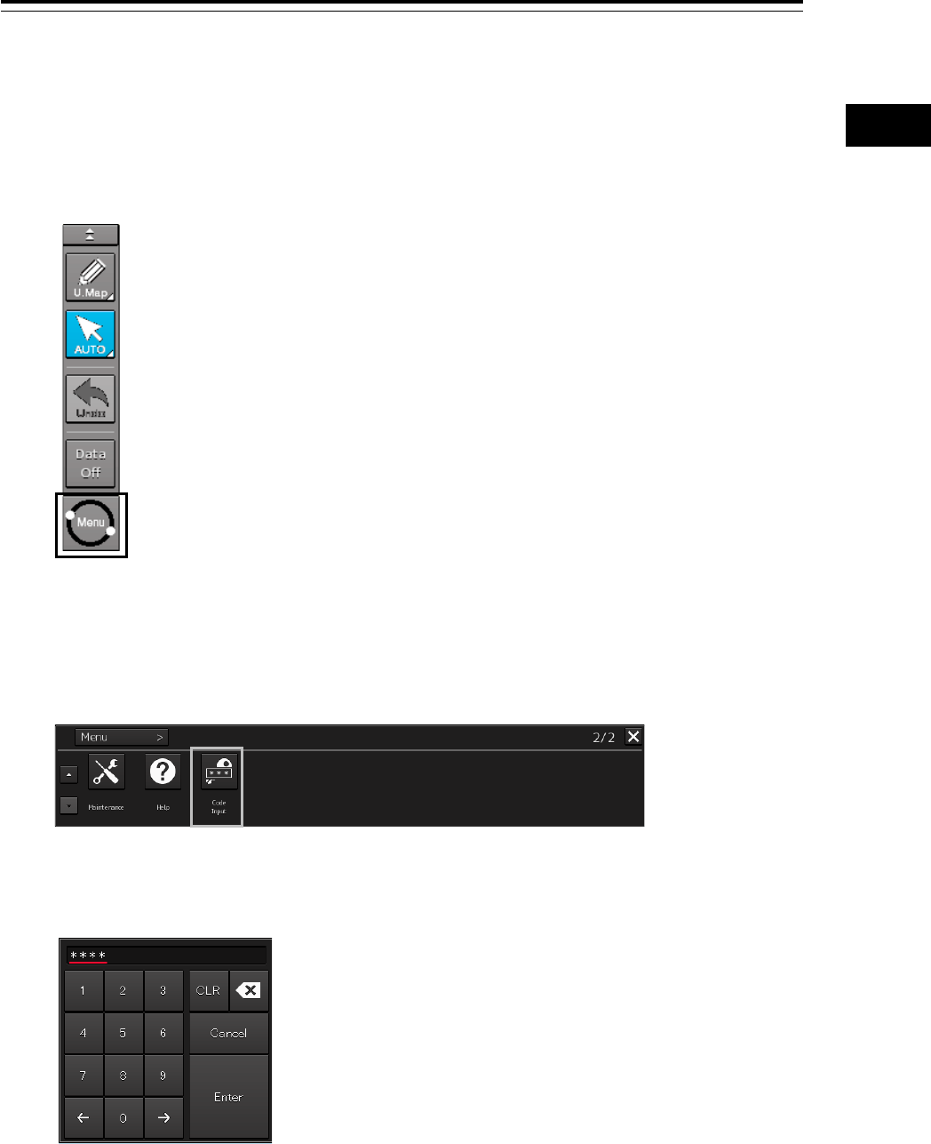
3.18 Password Input
Equipment settings are protected by a password. To open the dialog box of the protected setting
function, the password input is necessary.
Use the following procedure to enter a password.
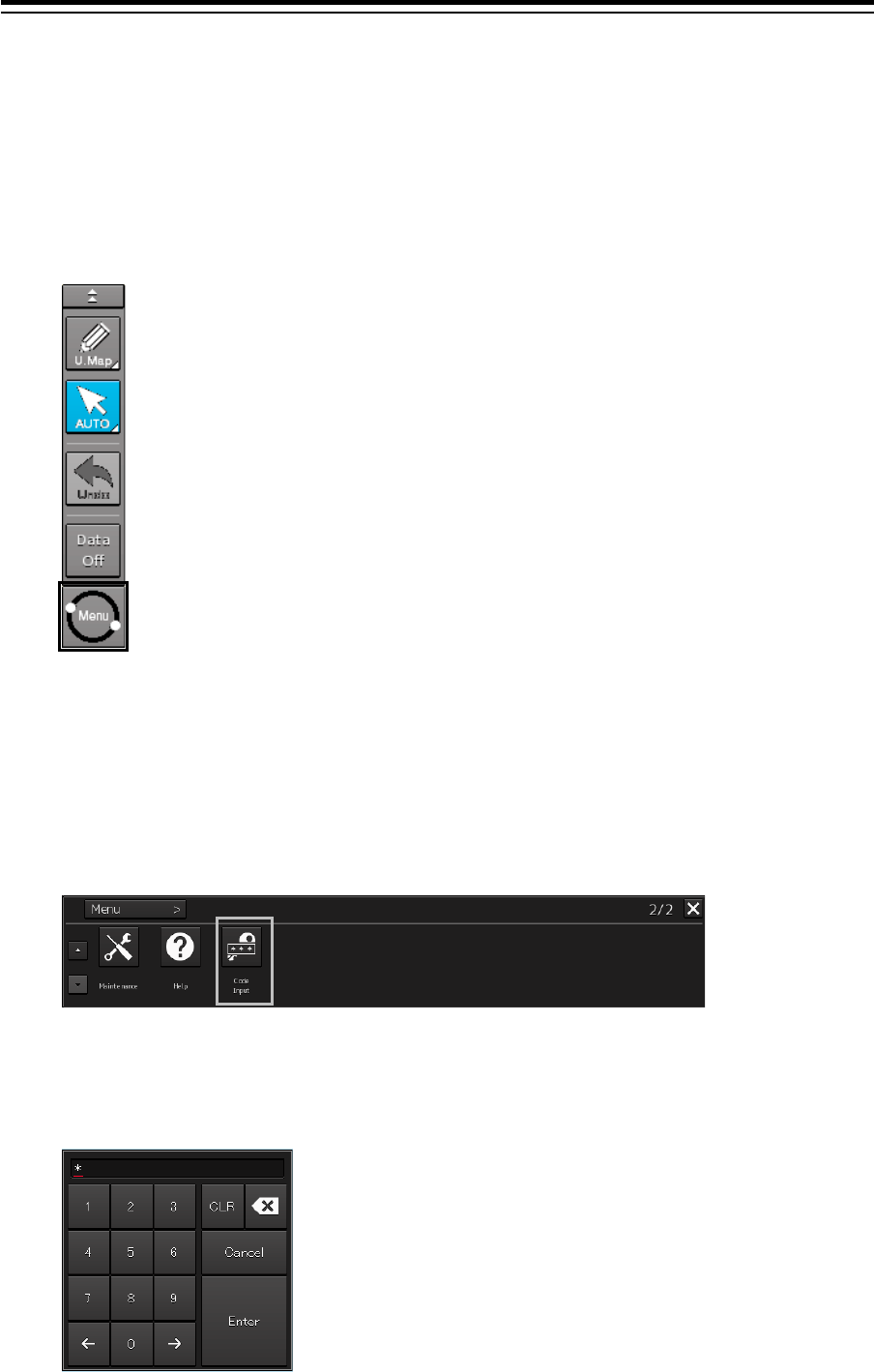
1 Click on the [Menu] button on the left toolbar.
The menu is displayed.
2 Change over to the second page of the menu using the page switching button of the
menu.
3 Click on the [Code Input] button on the Menu.
The password input dialog box appears.
4 Enter "0" (zero) and click on the [Enter] key.
3-81 Section 3 Common Basic Operations
1
2
3
4
5
6
7
8
9
10
11
12
13
14
15
16
17
18
19
20
21
22
23
24
25
APP A
APP B
1
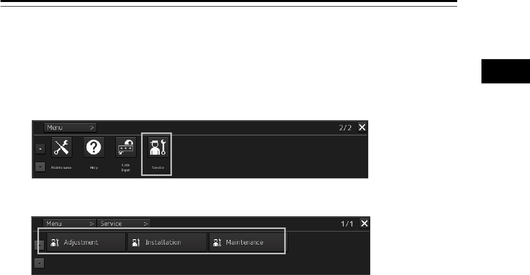
5 Display the menu by clicking again the [Menu] button on the left toolbar, and change
over to the second page using the page switching button.
The [Service] button is displayed in the menu.
6 Click on the [Service] button.
Check that service-related menus are displayed in the sub-menu.
Subsequently, service-related menus can be set.
Section 3 Common Basic Operations 3-82
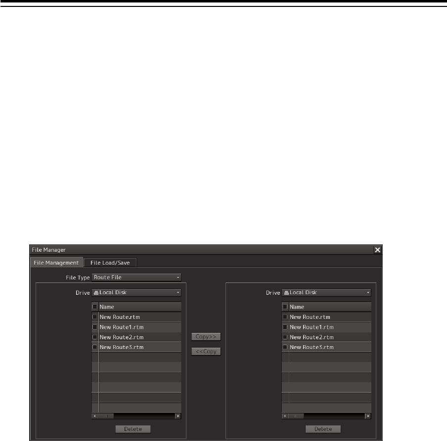
3.19 Managing Files with File Manager
The file manager function enables the copying of route files and user map from the hard disk of this
equipment to external storage media such as DVD or from external storage media to the hard disk of
this equipment.
3.19.1 Displaying the "File Manager" dialog box
1 Click on the [Menu] on the left toolbar.
The menu is displayed.
2 Click on the [Tools] - [File Manager] button on the menu.
The "File Manager" dialog box appears.
3-83 Section 3 Common Basic Operations
1
2
3
4
5
6
7
8
9
10
11
12
13
14
15
16
17
18
19
20
21
22
23
24
25
APP A
APP B
1
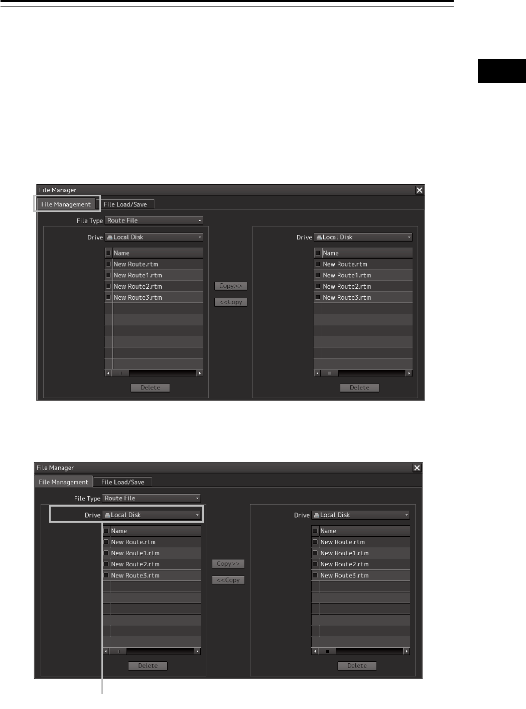
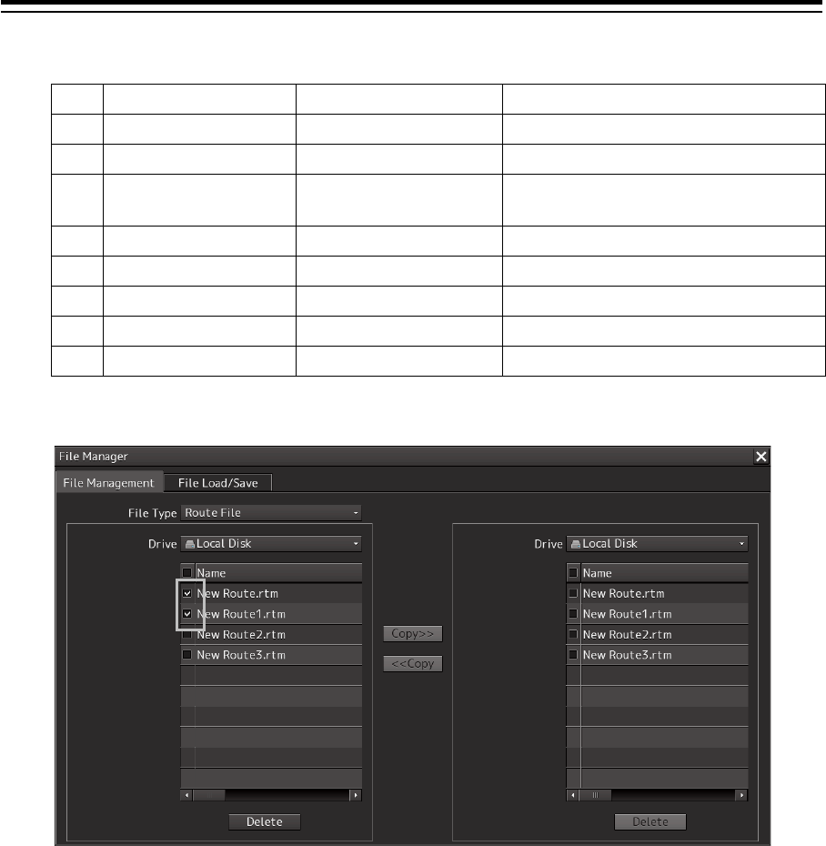
3.19.2 File management
The "File Management" tab enables file management.
File management copies files between SSD of this equipment and external storage media and deletes
files.
This section describes file management by using the example copying a file in the file list of the drive
that is specified in the [Drive] list on the left hand side of the dialog box to the drive that is specified in
the [Drive] list on the right hand side.
1 Click on the [File Management] tab.
2 Select the drive that contains the file to be copied from the [Drive] combo box.
Files in the drive are displayed in the list.
[Drive] combo box
Section 3 Common Basic Operations 3-84
The following file types can be displayed by the file manager.
No. File type File extension Contents
1 Route File rtm Route
2 User Map uchm User map
3 Target Track ttr Track of other ship (including the
GPS buoy)
4 Screen Shot (AUTO) png Automatically generated screen shot
5 Screen Shot (User) png Manually generated screen shot
6 Preferences ini Personal setting
7 Playback pbl, index, pbo, rot, pbt Playback data
8 Logbook lgb, lgblst Logbook (for up to 3 months)
3 Select the files to be copied by checking them.
3-85 Section 3 Common Basic Operations
1
2
3
4
5
6
7
8
9
10
11
12
13
14
15
16
17
18
19
20
21
22
23
24
25
APP A
APP B
1
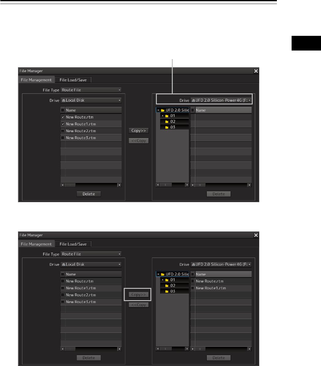
4 Select a drive of the storage destination from the [Drive] combo box and select a copy
location from the folder tree that is displayed.
5 Click on the [Copy>>] (copy to the right) button.
The files are copied.
When the drive of the copy source and the drive of the copy destination are reversed, click on
the [<<Copy] (copy to the left) in Step 5.
[Drive] combo box
Section 3 Common Basic Operations 3-86
Deleting a file
1 Click on the [Delete] button.
A deletion confirmation dialog is displayed.
2 To delete the file, click on the [OK] button.
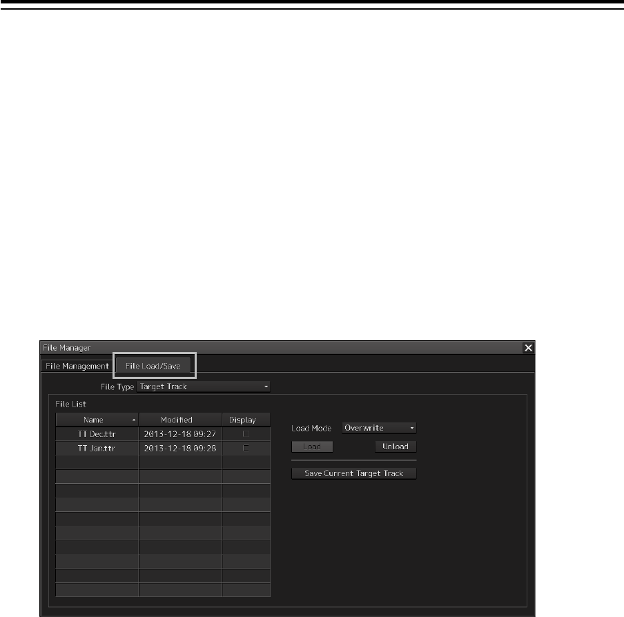
3.19.3 Loading and saving files
The [File Load/Save] tab enables loading and saving files.
3.19.3.1 Loading files
1 Click on the [File Load/Save] tab.
3-87 Section 3 Common Basic Operations
1
2
3
4
5
6
7
8
9
10
11
12
13
14
15
16
17
18
19
20
21
22
23
24
25
APP A
APP B
1
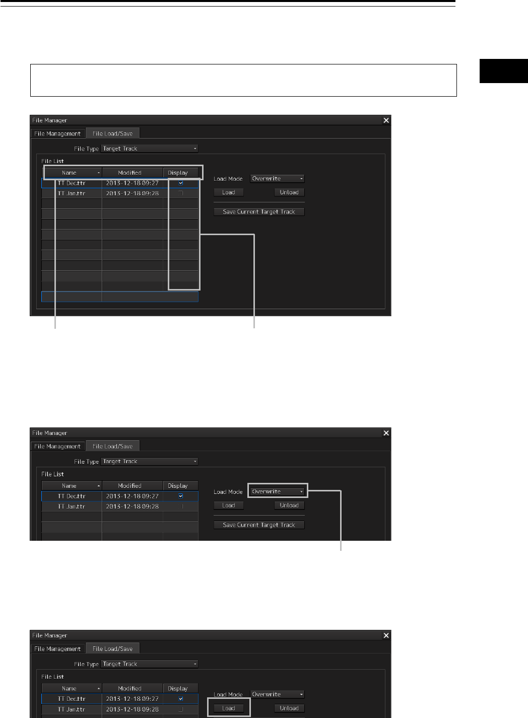
2 Check [Display] of the file to be loaded.
Memo
Only one file can be selected each time.
3 Select the file loading mode from the [Load Mode] combo box.
4 Click on the [Load] button.
A confirmation dialog box appears.
[Name] (file name)
[Modified] (last modified date)
[Display] (column check box)
Each title is sorted in the ascending/descending
order whenever the button is clicked on.
Temporarily displays the Track of the line that was
checked.
When the line is unchecked, the line is hidden.
One of the following modes
is displayed.
[Overwrite]
[Add]
Section 3 Common Basic Operations 3-88
5 Click on the [OK] button.
The selected file is loaded.
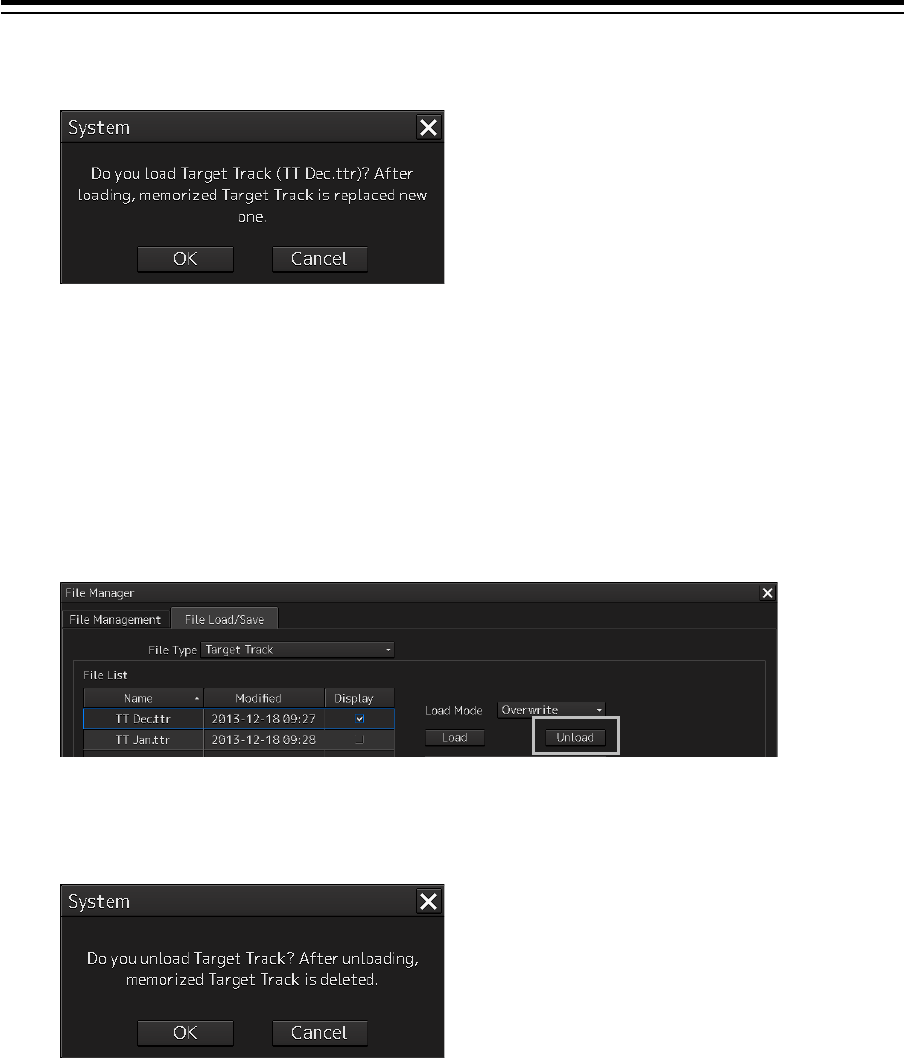
3.19.3.2 Unloading data (clearing data from the data screen)
1 Click on the "File Load/Save" tab.
2 Select a file type from the [File type] combo box.
3 Click on the [Unload] button.
A confirmation dialog box appears.
4 Click on the [OK] button.
The Target track data is cleared from the screen.
3-89 Section 3 Common Basic Operations
1
2
3
4
5
6
7
8
9
10
11
12
13
14
15
16
17
18
19
20
21
22
23
24
25
APP A
APP B
1
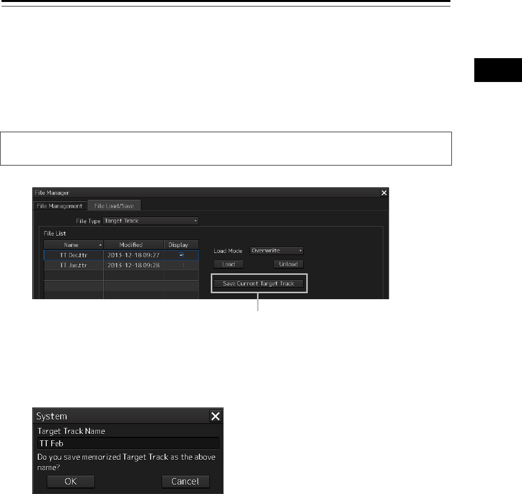
3.19.3.3 Saving files
1 Click on the [File Load/Save] tab.
2 Select a file type from the [File type] combo box.
3 Click on the [Save Current Target Track] button.
Memo
The name of the Save button varies according to the file type.
A confirmation dialog box appears
4 Enter a name under which the file is saved in the input box and click on the [OK]
button.
The Target Track that is stored is saved.
[Save Current Target Track]
button

Section 3 Common Basic Operations 3-90
3.20 Touch Panel (Option)
The table below shows the comparison between the touch operation (gesture) and the trackball
operation on the 26 or 19-inch touch panel LCD.
Refer to the instruction manual of the touch panel for the details of the touch panel.
Operation
Using trackball Using touch panel
Mouse
Touch panel
Mouse over - Display of main information
Display of operation guide
-
Click
Single tap
Selection of primary action
Display of context menu
Double click Double tap Exiting from line/route
creation
Exiting from line/route
creation
Selection of primary action
(except during creation of
line/route)
Click right button
Long tap
Display of context menu
Display of context menu
3-91 Section 3 Common Basic Operations
1
2
3
4
5
6
7
8
9
10
11
12
13
14
15
16
17
18
19
20
21
22
23
24
25
APP A
APP B
1
3.21 Returning to a Task Menu by Ending
the Operation
1 Click on the [MENU] on the left toolbar.
The menu is displayed.
2 Change over to the second page of the menu using the page switching button of the
menu.
3 Click on the [Code Input] button on the menu.
The password input dialog box appears.
4 Enter 9999 and click on the [Enter] key.
Section 3 Common Basic Operations 3-92
Returns to the task menu.
3-93 Section 3 Common Basic Operations
1
2
3
4
5
6
7
8
9
10
11
12
13
14
15
16
17
18
19
20
21
22
23
24
25
APP A
APP B
1
3.22 Terminating this equipment
When turning off the power supply, do not hold down the power button of the
operation unit.
Otherwise, a trouble may occur due to termination failure.
1 Press the power supply button on the operation unit.
The power is turned off and the light of power supply button goes off.
Section 3 Common Basic Operations 3-94
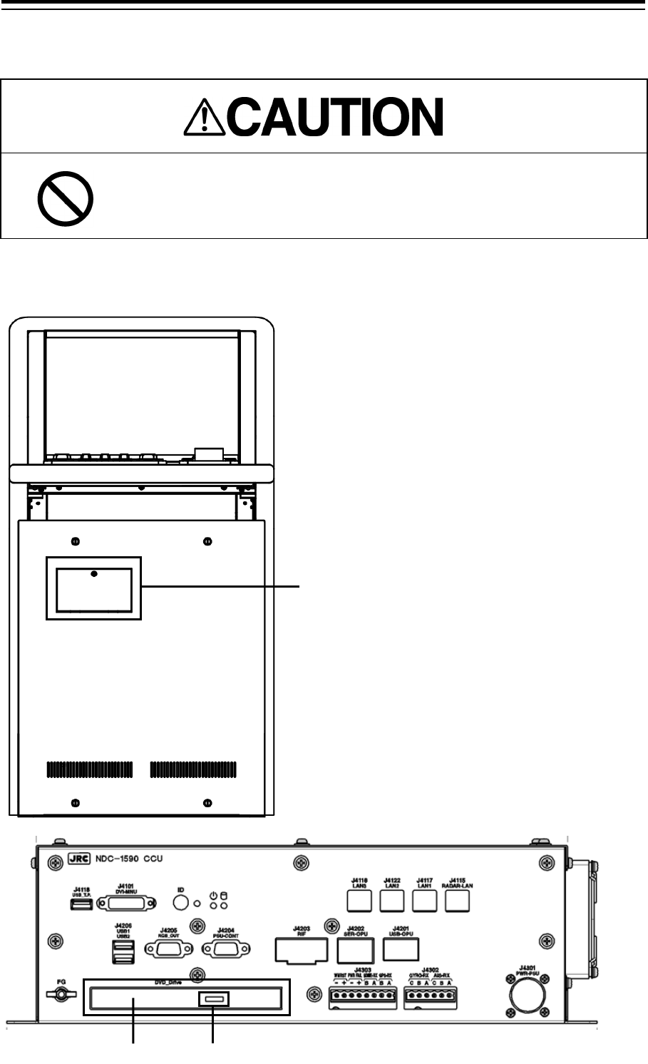
3.23 Using a DVD Drive
Do not leave the disc in the DVD drive.
Malfunctions of the drives may result.
A DVD drive is installed in the panel of this equipment.
Use the drive by removing the panel.
Remove the panel.
Eject button
DVD drive

3-95 Section 3 Common Basic Operations
1
2
3
4
5
6
7
8
9
10
11
12
13
14
15
16
17
18
19
20
21
22
23
24
25
APP A
APP B
1
Note
Do not remove a DVD disk while the access lamp of the DVD drive is lit.

Section 3 Common Basic Operations 3-96

4-1 Section 4 Range and Bearing Measurement Methods
1
2
3
4
5
6
7
8
9
10
11
12
13
14
15
16
17
18
19
20
21
22
23
24
25
APP A
APP B
1
Section 4
Range and Bearing
Measurement Methods
4.1 List of Measuring Tools
This equipment is equipped with the following measuring tools to measure the range and bearing.
Measuring tool Function Related section
Cross-Hair Cursor
(Cursor)
Used to measure the range and bearing from
the own ship’s position.
4.3 Using the Cross-hair
Cursor
Range Rings Displays concentric circles having CCRP
(Consistent Common Reference Point) as the
center at constant intervals in order to be used
as guidance for measuring the range.
4.4 Using the Range Rings
Electronic Bearing
Lines (EBL1/EBL2)
Displays a straight line that specifies an
arbitrary bearing in order to measure the
bearing from own ship.
The MFD is equipped with two electronic
bearing lines (EBL1 and EBL2).
4.5 Using the Electronic
Bearing Line (EBL) and
Variable Range Marker
(VRM)
Variable Range
Markers
(VRM1/VRM2)
Displays a circle that specifies an arbitrary
range in order to measure the range from own
ship.
The MFD is equipped with two variable range
markers (VRM1 and VRM2).
Parallel Index Lines
(PI)
Displays a group of straight lines at equal
intervals in order to be used for complex
measurement and guidance for route.
4.6 sing Parallel Index
Lines (PI)
EBL Maneuver Displays a predictable track when own ship is
turned in order to be used as guidance for
maneuvering.
4.7 Using the EBL
Maneuver
Node Fixed
EBL/VRM
Connects the own ship’s position and the
specified fixed position with EBL and VRM
markers.
Since the connection is maintained even if own
ship advances, the bearing and range of own
ship against the fixed position is always
available.
4.8 Connecting Own Ship
and the Specified Fixed
Position with EBL and the
VRM Marker (Node Fixed
EBL/VRM Function)
Manual position fix
(LOPs)
Measures the own ship’s position with LOP
(Line Of Position) and plots it on the chart. The
own ship’s position can be jumped to the
plotted position.
4.9 Measuring the Own
Ship’s Position Manually
(LOPs Fixing Function of
Manual position fix)
Manual position fix
(Position Offset)
Enables offsetting the own ship’s position with
manual operation.
4.10 Offsetting the Own
Ship’s Position Manually
(Position Offset Function of
Manual position fix)
Section 4 Range and Bearing Measurement Methods 4-2
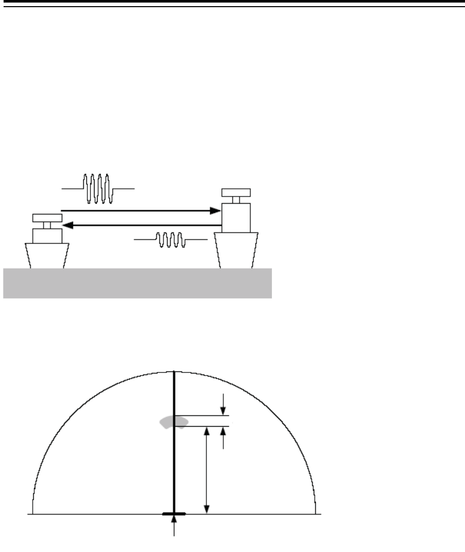
4.2 Target Position
The radar transmits the pulse-modulated radio waves. The transmitted waves are received in the
target after being reflected (echoed). On the screen, the waves spread in the pulse width range
direction based on the target position as the front edge.
When measuring a target or setting a mark/line on the target, place the cursor on the front edge of the
echo.
Radar transmission/reception
Relationship of range between the echo and the target and the pulse width
Pulse transmission
Reflected wave
270
90
0
Pulse width
Target range
Own ship’s position
4-3 Section 4 Range and Bearing Measurement Methods
1
2
3
4
5
6
7
8
9
10
11
12
13
14
15
16
17
18
19
20
21
22
23
24
25
APP A
APP B
1
4.3 Using the Cross-hair Cursor
When moving the cursor into a window, it changes to a cross-hair cursor. With the cross-hair cursor,
the bearing and position of a target can be measured.
The information that is measured by the cursor is displayed in the cursor readout information area.
4.3.1 Cursor readout information area display
position
The display method of the cursor readout information area varies between RADAR and ECDIS.
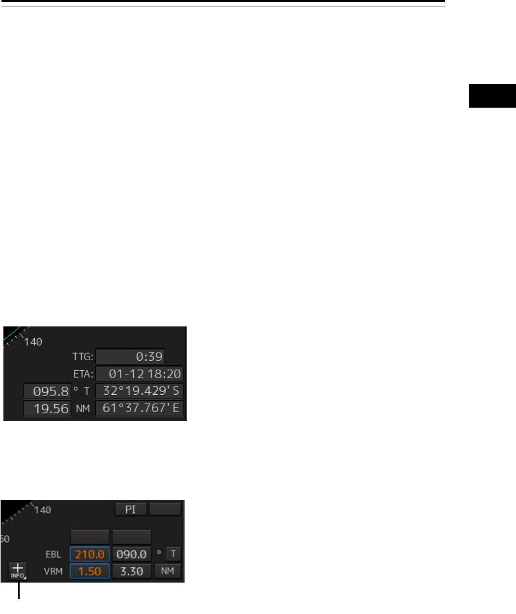
4.3.1.1 RADAR
The information can be displayed by either of the following methods.
[Placing the cursor inside of PPI]
When the cursor is placed inside of PPI, the cursor information on the position at which the cursor is
placed is displayed in the bottom right corner of the screen.
[Clicking on the cursor information display button at the bottom right corner of the screen]
When the cursor information display button on the bottom right corner of the screen is clicked on, the
"Cursor readout" dialog is displayed.
The display mode of the "Cursor readout" dialog can be switched between standard display and
expanded display by clicking on the Disclosure button.
Cursor information display button
Section 4 Range and Bearing Measurement Methods 4-4
To close the "Cursor readout" dialog box
Click the [X] button.
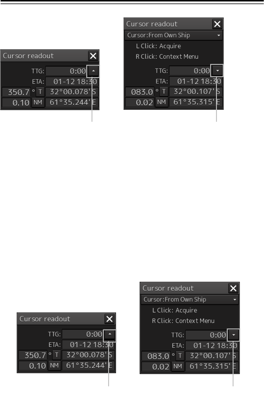
4.3.1.2 ECDIS
Use the following method to display the information.
1 Click the [Menu] button on the left toolbar.
The menu is displayed.
2 Click on [Tools] - [Cursor Readout] on the menu.
The "Cursor readout" dialog box appears.
The display mode of the "Cursor readout" dialog can be switched between standard display and
expanded display by clicking on the Disclosure button.
To close the "Cursor readout" dialog box
Click the [X] button.
Disclosure button
Disclosure button
Standard display
Expanded display
Disclosure button
Disclosure button
Standard display
Expanded display
4-5 Section 4 Range and Bearing Measurement Methods
1
2
3
4
5
6
7
8
9
10
11
12
13
14
15
16
17
18
19
20
21
22
23
24
25
APP A
APP B
1
4.3.2 Measuring the bearing and the range from the
own ship’s position to the target by using the
cross-hair cursor
The measurement method is as follows.
Memo
When placing the cursor on the target, place the cursor on the front edge (towards the own ship of
the echo) (CCRP side) of the echo.
4.3.2.1 Measuring by using the cursor information that is
displayed by placing the cursor inside of PPI (RADAR
only)
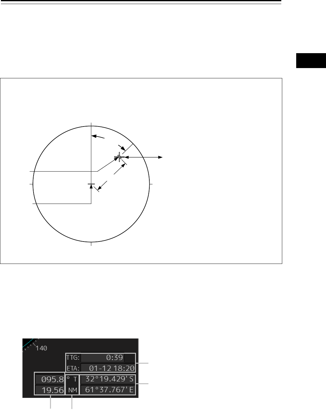
1 Place the cursor on the target.
When the cursor is placed on the target, the following cursor information is displayed.
[1] TTG display and ETA display
Displays TTG and ETA from the own ship’s position to the cursor position.
[2] Latitude and longitude of the cursor position
Displays the latitude and the longitude of the cursor position.
45.0°
180
0
90270
6.00NM
Bearing and range from the own ship’s
position to the target in this figure:
True bearing: 45.0°
Range: 6.00 NM
Cursor
(Should not place the cursor at the center
of the echo, place the cursor at the front of
the echo's edge)
Target
CCRP
[1]
[2]
[4]
[3]
Section 4 Range and Bearing Measurement Methods 4-6
[3] Cursor bearing True/Relative display and cursor range unit display
Displays the cursor bearing True/Relative display setting and the cursor range unit that were set in the
"Cursor readout" dialog.
[4] Cursor bearing display and cursor range display
Displays the bearing and range from CCRP to the cursor.
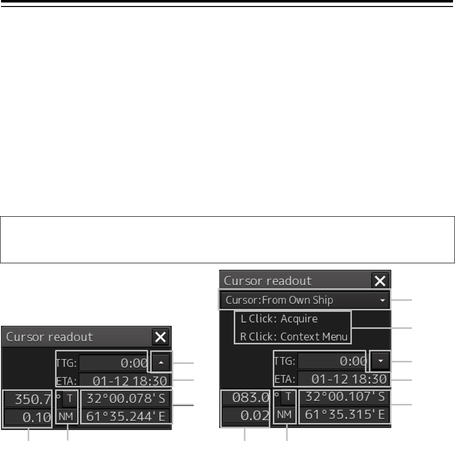
4.3.2.2 Measuring by using the "Cursor readout" dialog
When the cursor is placed on the target, the cursor information is displayed on the "Cursor readout"
dialog.
Memo
The "Cursor readout" dialog can also be displayed by selecting [Too l s] - [Cursor Readout] on the
menu.
[1] Cursor bearing/range reference point switching combo box
Set a cursor bearing/range reference point.
* Only [Cursor:From Own Ship] which makes own ship’s position a bearing/range reference point to
the cursor can be selected.
[2] Operation hint
Displays the operation hint of the trackball button.
[3] Disclosure button
By clicking on the button, the display mode of the "Cursor readout" dialog can be switched between
standard display and expanded display.
[4] TTG display and ETA display
Displays TTG and ETA from the ship’s own position to the cursor position.
[5] Latitude and longitude of the cursor position
Displays the latitude and longitude of the cursor position.
[3]
[3]
[1]
[2]
[5]
[6]
[6]
[7]
[7]
[4]
[4]
[5]
Standard display
Expanded display
4-7 Section 4 Range and Bearing Measurement Methods
1
2
3
4
5
6
7
8
9
10
11
12
13
14
15
16
17
18
19
20
21
22
23
24
25
APP A
APP B
1
[6] Cursor bearing True/Relative display and cursor range unit display
For the details, refer to "4.3.2.3 Switching the cursor bearing between True/Relative" and "4.3.2.4
Switching the cursor range unit".
[7] Cursor bearing display and cursor range display
Displays the bearing and range from CCRP to the cursor.
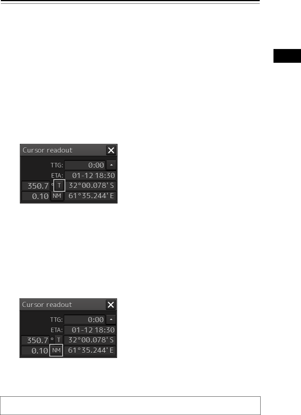
4.3.2.3 Switching the cursor bearing between True/Relative
The cursor bearing mode can be switched between True/Relative in the "Cursor readout" dialog box.
1 Display the "Cursor readout" dialog box.
2 Click on the cursor bearing True/Relative switching button.
Whenever the button is clicked on, the display is switched between [T] and [R].
[T]: Displays the cursor bearing in True mode.
[R]: Displays the cursor bearing in Relative mode.
4.3.2.4 Switching the cursor range unit
The cursor range unit can be switched in the "Cursor readout" dialog box.
1 Display the "Cursor readout" dialog box.
2 Click on the cursor range unit switching button.
Whenever the button is clicked on, the display is switched to [NM], [sm], or [km].
[NM]: Displays the range in the unit of NM.
[sm]: Displays the range in the unit of sm.
[km]: Displays the range in the unit of km.
Memo
NM indicates nautical miles, sm indicates surface miles, and km indicates kilometers.
Section 4 Range and Bearing Measurement Methods 4-8
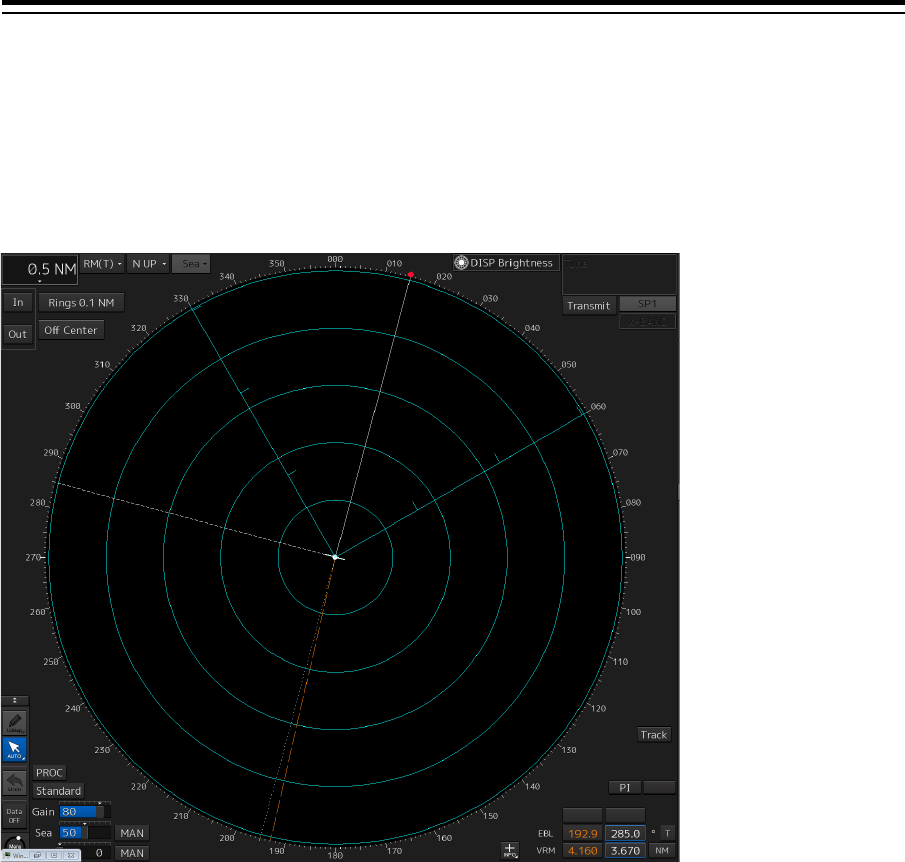
4.4 Using the Range Rings
Range rings are multiple concentric circles displayed on the PPI screen.
Using range rings on the PPI screen, the range to a target can be measured by determining at which
scale interval the target is positioned.
4-9 Section 4 Range and Bearing Measurement Methods
1
2
3
4
5
6
7
8
9
10
11
12
13
14
15
16
17
18
19
20
21
22
23
24
25
APP A
APP B
1
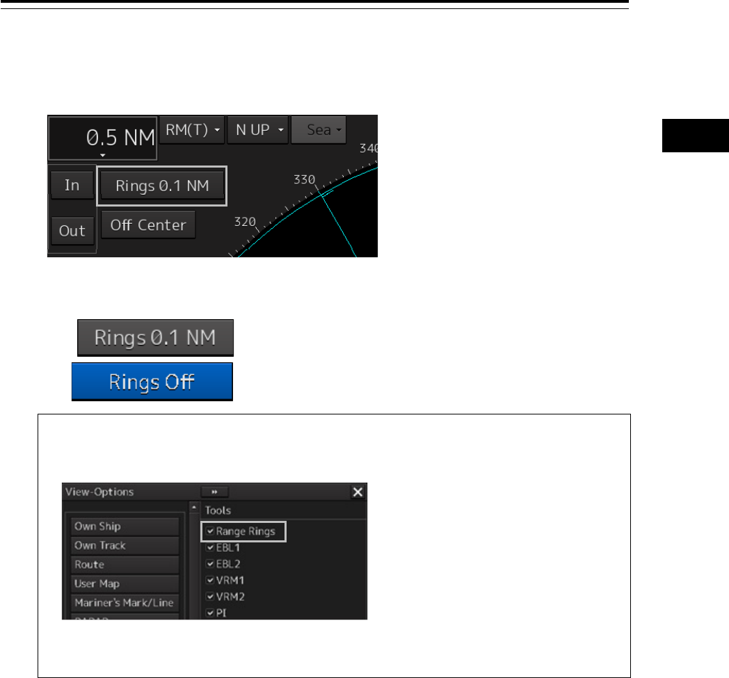
The display of range rings can be turned on/off according to the following procedure.
1 Click the Rings button in Presentation and mode information.
Each time this button is clicked on, display switches between On and Off.
On:
Off:
Memo
For ECDIS, Range Rings can be switched to On/Off in the "View-Options" dialog that is
displayed by selecting the [View] - [Options] - [Tools] on the menu.
The color and brilliance of Range Rings can be set. For the detais, refer to "16.2.13 Setting
up the Display of Range/Bearing Measurement Function".
Section 4 Range and Bearing Measurement Methods 4-10
4.5 Using the Electronic Bearing Line
(EBL) and Variable Range Marker
(VRM)
4.5.1 Measuring a range and a bearing with EBL
and VRM
4.5.1.1 Measuring in the trackball operation unit
When the cursor is in AUTO mode, EBL and VRM can be operated on the trackball operation unit.
This section describes the manipulation under EBL1 and VRM1; however, the same manipulation can
be performed under EBL2 and VRM2 also.
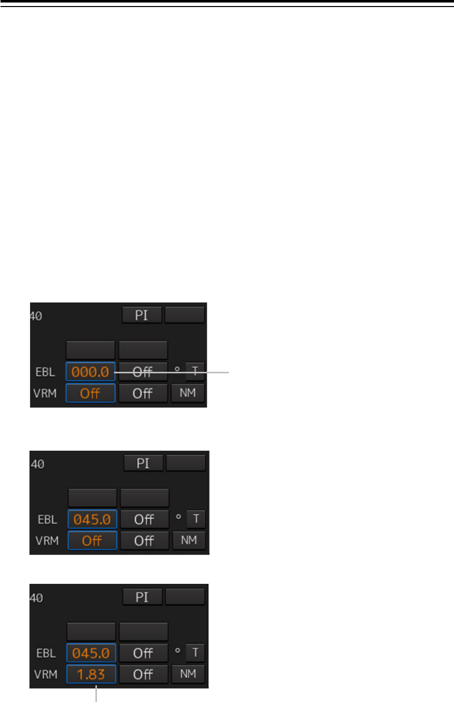
1 Enable the manipulation of EBL1 by clicking on the [EBL1] button.
2 Align the cursor with a target and click on the mouse button.
The bearing of the target is displayed on the [EBL1] button.
3 Enable the manipulation of VRM1 by clicking on the [VRM1] button.
[EBL1] button
[VRM1] button
4-11 Section 4 Range and Bearing Measurement Methods
1
2
3
4
5
6
7
8
9
10
11
12
13
14
15
16
17
18
19
20
21
22
23
24
25
APP A
APP B
1
4 Align the cursor with a target and click on the mouse button.
The range of the target is displayed on the [VRM1] button.
4.5.1.2 Measuring with the [EBL] or [VRM] dial on the keyboard
operation unit
1 Press the [EBL] dial.
The context menu is displayed.
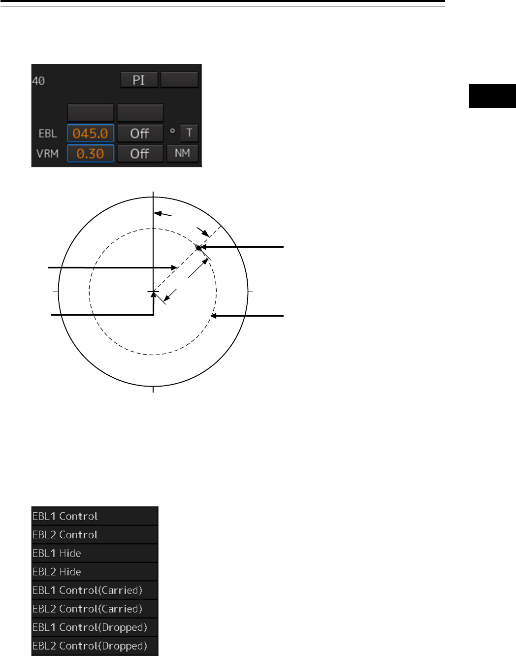
2 By turning the dial, select either [EBL1 Control] or [EBL2 Control].
VRM1
Target
CCRP
EBL1
Bearing and range from the own ship's
position to the target in this figure:
True bearing 45.0°
Range 0.30 NM
180
0
90270 0.3NM
45.0°
Section 4 Range and Bearing Measurement Methods 4-12
3 Press the [EBL] dial.
If [EBL1 Control] is being selected, manipulation of EBL1 is enabled.
If [EBL2 Control] is being selected, manipulation of EBL 2 is enabled.
4 By turning the [EBL] dial, align the EBL with a target.
The bearing of the target is displayed on the [EBL1] button.
5 Press the [VRM] dial.
The context menu is displayed.
6 By turning the dial, select either [VRM1 Control] or [VRM2 Control].
7 Press the [VRM] dial.
If [VRM1 Control] is being selected, manipulation of VRM1 is enabled.
If [VRM2 Control] is being selected, manipulation of VRM2 is enabled.
8 By turning the [VRM] dial, align the VRM with a target.
The range of the target is displayed on the [VRM1] button.
VRM1
Target
CCRP
EBL1
Bearing and range from the own ship's
position to the target in this figure:
True bearing 45.0°
Range 0.30 NM
180
0
90270 0.3NM
45.0°
4-13 Section 4 Range and Bearing Measurement Methods
1
2
3
4
5
6
7
8
9
10
11
12
13
14
15
16
17
18
19
20
21
22
23
24
25
APP A
APP B
1
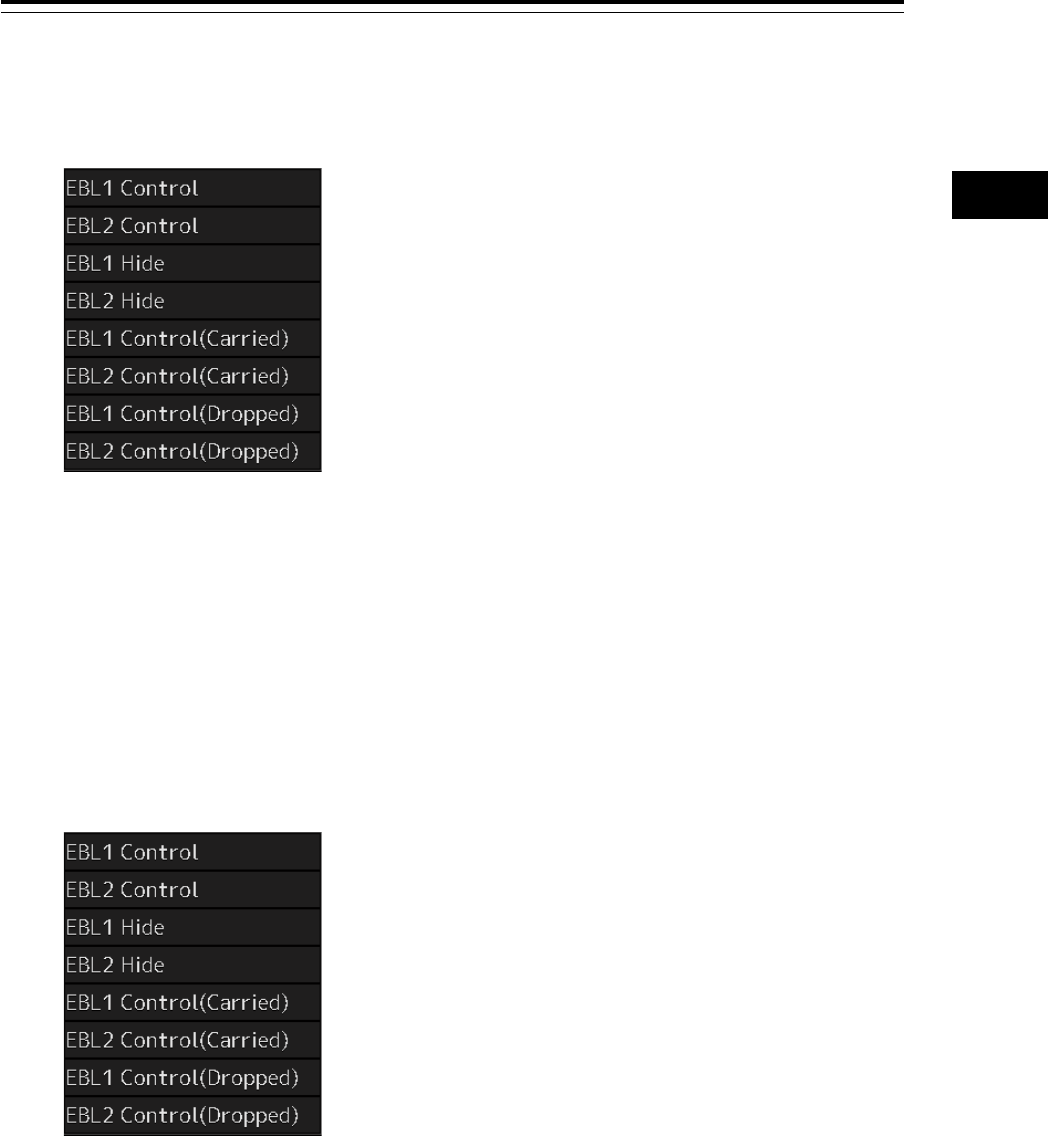
To clear the EBL:
1 Press the [EBL] dial.
The context menu is displayed.
2 By turning the dial, select either [EBL1 Hide] or [EBL2 Hide].
3 Press the [EBL] dial.
If [EBL1 Hide] is being selected, the selection of EBL1 is cleared.
If [EBL2 Hide] is being selected, the selection of EBL2 is cleared.
To change the measurement starting point of the EBL:
The measurement starting point can be changed from the own ship's position to another.
1 Press the [EBL] dial.
The context menu is displayed.
2 By turning the dial, select either [EBL1 Control (Carried)] and [EBL1 Control (Dropped)]
or [EBL2 Control (Carried)] and [EBL2 Control (Dropped)].
3 Press the [EBL] dial.
If [EBL1 Control (Carried)] and [EBL1 Control (Dropped)] is being selected, manipulation of
EBL1 is enabled.
If [EBL2 Control (Carried)] and [EBL2 Control (Dropped)] is being selected, manipulation of
EBL2 is enabled.
4 Move the cursor to change the measurement starting point.
The measurement starting point is fixed by clicking on it.
Section 4 Range and Bearing Measurement Methods 4-14
To clear the VRM:
1 Press the [VRM] dial.
The context menu is displayed.
2 By turning the dial, select either [VRM1 Hide] or [VRM2 Hide].
3 Press the [VRM] dial.
If [VRM1 Hide] is being selected, the selection of VRM1 is cleared.
If [VRM2 Hide] is being selected, the selection of VRM2 is cleared.
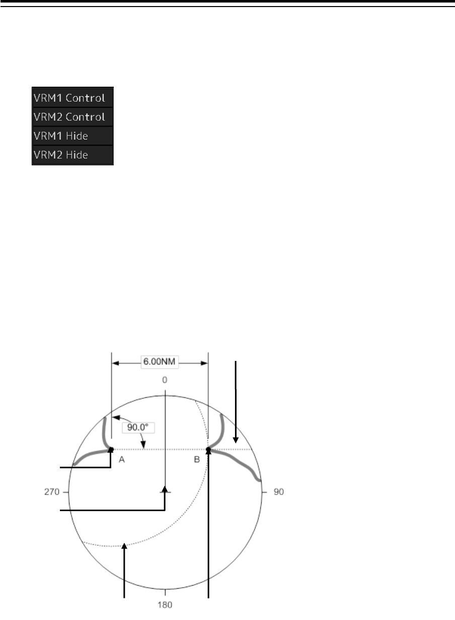
4.5.2 Measuring between arbitrary two points
The range and bearing between arbitrary two points can be measured as follows.
Here, the manipulation with EBL2/VRM2 is explained. The same operation can be performed with
EBL1/VRM1.
EBL2
Cape
VRM2
CCRP
Cape
4-15 Section 4 Range and Bearing Measurement Methods
1
2
3
4
5
6
7
8
9
10
11
12
13
14
15
16
17
18
19
20
21
22
23
24
25
APP A
APP B
1
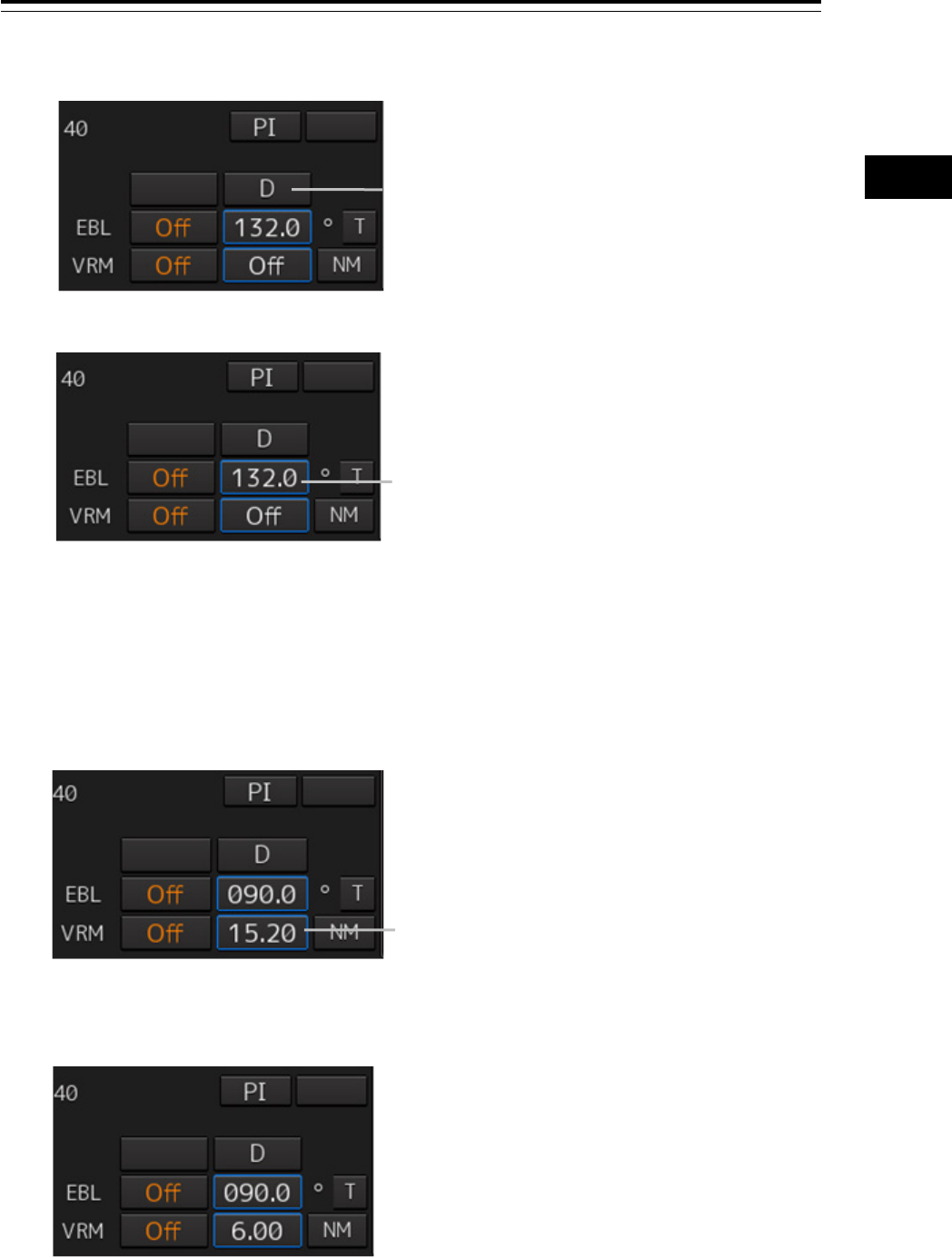
1 Click on the measurement starting point button of EBL2/VRM2 and select [D].
2 Enable the manipulation of EBL2 by clicking on the [EBL2] button.
3 Align the cursor with “point A” of the two points to be measured and then click it on.
4 Enable the movement of EBL2 by clicking on the EBL2 line.
5 Align the cursor with bearing “point B” of the two points to be measured and then click
it on.
6 Click the [VRM2] button to make VRM2 operable.
7 Move the intersecting point marker on the dotted line of EBL2 by the cursor and align it
with point B.
The range and bearing between the two points are displayed.
Measurement starting point button
[EBL2] button
[VRM2] button

Section 4 Range and Bearing Measurement Methods 4-16
4.5.3 Manipulating EBL/VRM with the context menu
(ECDIS only)
EBL/VRM can be manipulated with the context menu that appears by clicking on the screen.
The context menu of EBL/VRM consists of "Dropped EBL/VRM" that manipulates EBL/VRM by using
an arbitrary position as the measurement starting point, and "CCRP EBL/VRM" that manipulates
EBL/VRM by using the position of own ship as the measurement starting point.
Context menu
Related section
[Dropped EBL/VRM] - [Make EBL1/VRM1] or
[Make EBL2/VRM2]
4.5.3.1 Manipulating EBL/VRM with [Dropped
EBL/VRM] - [Make EBL1/VRM1] or [Make
EBL2/VRM2]
[Dropped EBL/VRM] - [Make EBL1] or [Make
EBL2]
4.5.3.2 Manipulating EBL with [Dropped
EBL/VRM] - [Make EBL1] or [Make EBL2]
[Dropped EBL/VRM] - [Make VRM1] or [Make
VRM2]
4.5.3.3 Manipulating VRM with [Dropped
EBL/VRM] - [Make VRM1] or [Make VRM2]
[Dropped EBL/VRM] - [Move base point of
EBL1/VRM1] or [Move base point of
EBL2/VRM2]
4.5.3.4 Manipulating EBL/VRM with [Dropped
EBL/VRM] - [Move base point of EBL1/VRM1] or
[Move base point of EBL2/VRM2]
[CCRP EBL/VRM] - [Make EBL1/VRM1] or
[Make EBL2/VRM2]
4.5.3.5 Manipulating EBL/VRM with [CCRP
EBL/VRM] - [Make EBL1/VRM1] or [Make
EBL2/VRM2]
[CCRP EBL/VRM] - [Make EBL1] or [Make
EBL2]
4.5.3.6 Manipulating EBL with [CCRP EBL/VRM]
- [Make EBL1] or [Make EBL2]
[CCRP EBL/VRM] - [Make VRM1] or [Make
VRM2]
4.5.3.7 Manipulating VRM with [CCRP
EBL/VRM] - [Make VRM1] or [Make VRM2]
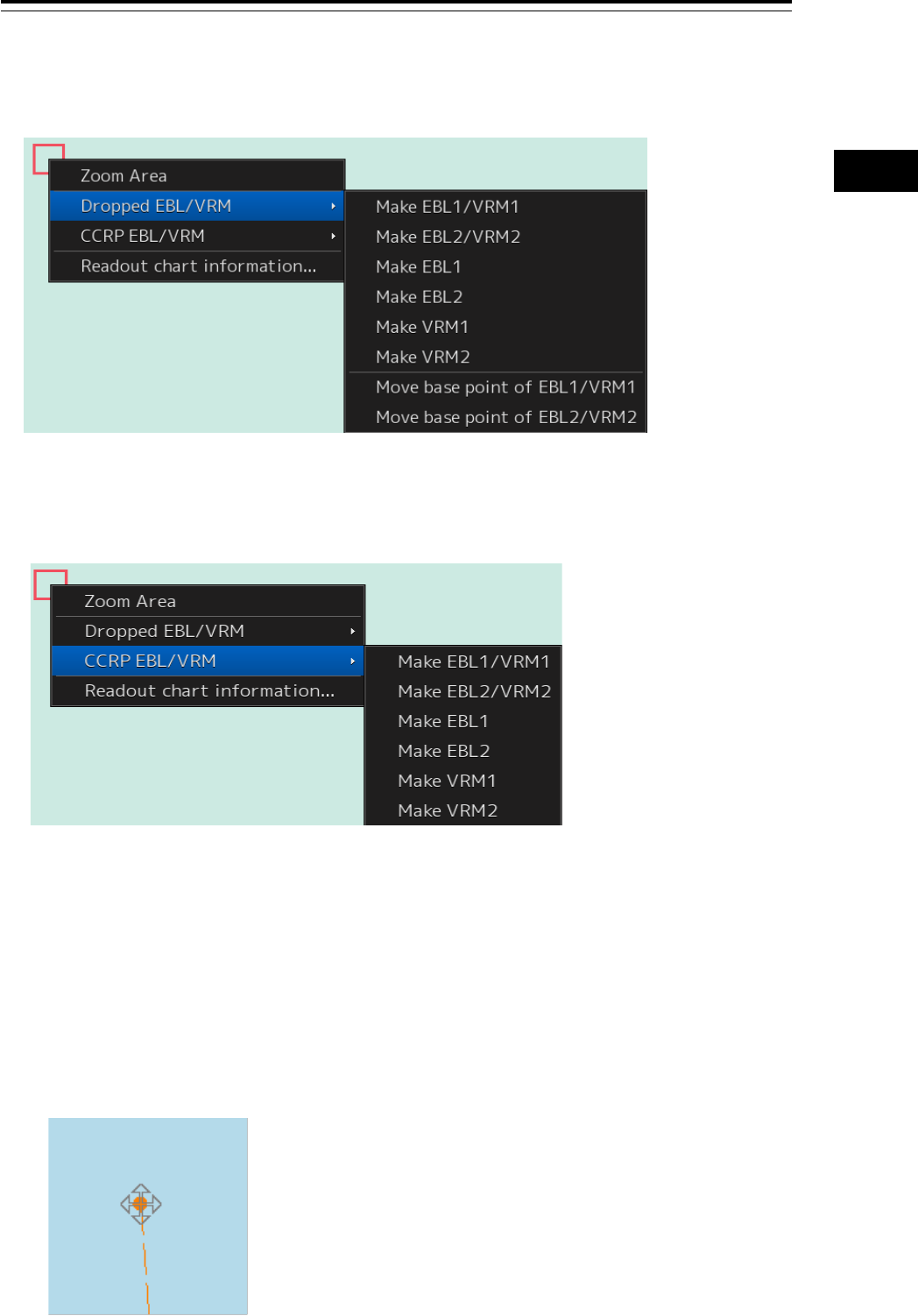
4-17 Section 4 Range and Bearing Measurement Methods
1
2
3
4
5
6
7
8
9
10
11
12
13
14
15
16
17
18
19
20
21
22
23
24
25
APP A
APP B
1
[Dropped EBL/VRM]
On this context menu, EBL/VRM can be manipulated by using the measuring reference point as any
position.
[CCRP EBL/VRM]
On this context menu, EBL/VRM can be manipulated by using the measuring reference point as the
own ship’s position.
4.5.3.1 Manipulating EBL/VRM with [Dropped EBL/VRM] - [Make
EBL1/VRM1] or [Make EBL2/VRM2]
The manipulations of EBL1/VRM1 and EBL2/VRM2 are the same. Here, the manipulation of
EBL1/VRM1 is explained as an example.
1 Right-click on the screen to display the context menu.
2 Select [Dropped EBL/VRM] - [Make EBL1/VRM1] on the context menu.
EBL1 is displayed and then the measurement starting point appears on the cursor.
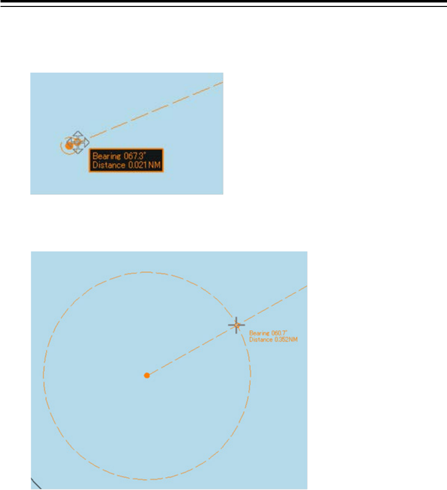
Section 4 Range and Bearing Measurement Methods 4-18
3 Move the cursor and click on at an arbitrary position.
The measurement starting point is fixed.
4 Move the cursor and click on at an arbitrary position.
The EBL1 bearing and the VRM1 range are fixed.
4.5.3.2 Manipulating EBL with [Dropped EBL/VRM] - [Make EBL1]
or [Make EBL2]
The manipulations of EBL1 and EBL2 are the same. Here, the manipulation of EBL1 is explained as an
example.
1 Right-click on the screen to display the context menu.
2 Select [Dropped EBL/VRM] - [Make EBL1] on the context menu.
EBL1 is displayed and then the measurement starting point appears on the cursor.
3 Move the cursor and click on at an arbitrary position.
The measurement starting point is fixed.
4 Move the cursor and click on at an arbitrary position.
The EBL1 bearing is fixed.

4-19 Section 4 Range and Bearing Measurement Methods
1
2
3
4
5
6
7
8
9
10
11
12
13
14
15
16
17
18
19
20
21
22
23
24
25
APP A
APP B
1
4.5.3.3 Manipulating VRM with [Dropped EBL/VRM] - [Make VRM1]
or [Make VRM2]
The manipulations of VRM1 and VRM2 are the same. Here, the manipulation of VRM1 is explained as
an example.
1 Right-click on the screen to display the context menu.
2 Select [Dropped EBL/VRM] - [Make VRM1] on the context menu.
VRM1 is displayed and then the measurement starting point appears on the cursor.
3 Move the cursor and click on at an arbitrary position.
The measurement starting point is fixed.
4 Move the cursor and click on at an arbitrary position.
The VRM1 range is fixed.
4.5.3.4 Manipulating EBL/VRM with [Dropped EBL/VRM] - [Move
base point of EBL1/VRM1] or [Move base point of
EBL2/VRM2]
The manipulations of [Move base point of EBL1/VRM1] and [Move base point of EBL2/VRM2] are the
same. Here, the manipulation of [Move base point of EBL1/VRM1] is explained as an example.
1 Right-click on the screen to display the context menu.
2 Select [Dropped EBL/VRM] - [Move base point of EBL1/VRM1] on the context menu.
EBL1 and VRM1 are displayed, and then the measurement starting point appears on the cursor.
3 Move the cursor and click on at an arbitrary position.
The measurement starting point of EBL/VRM is fixed.
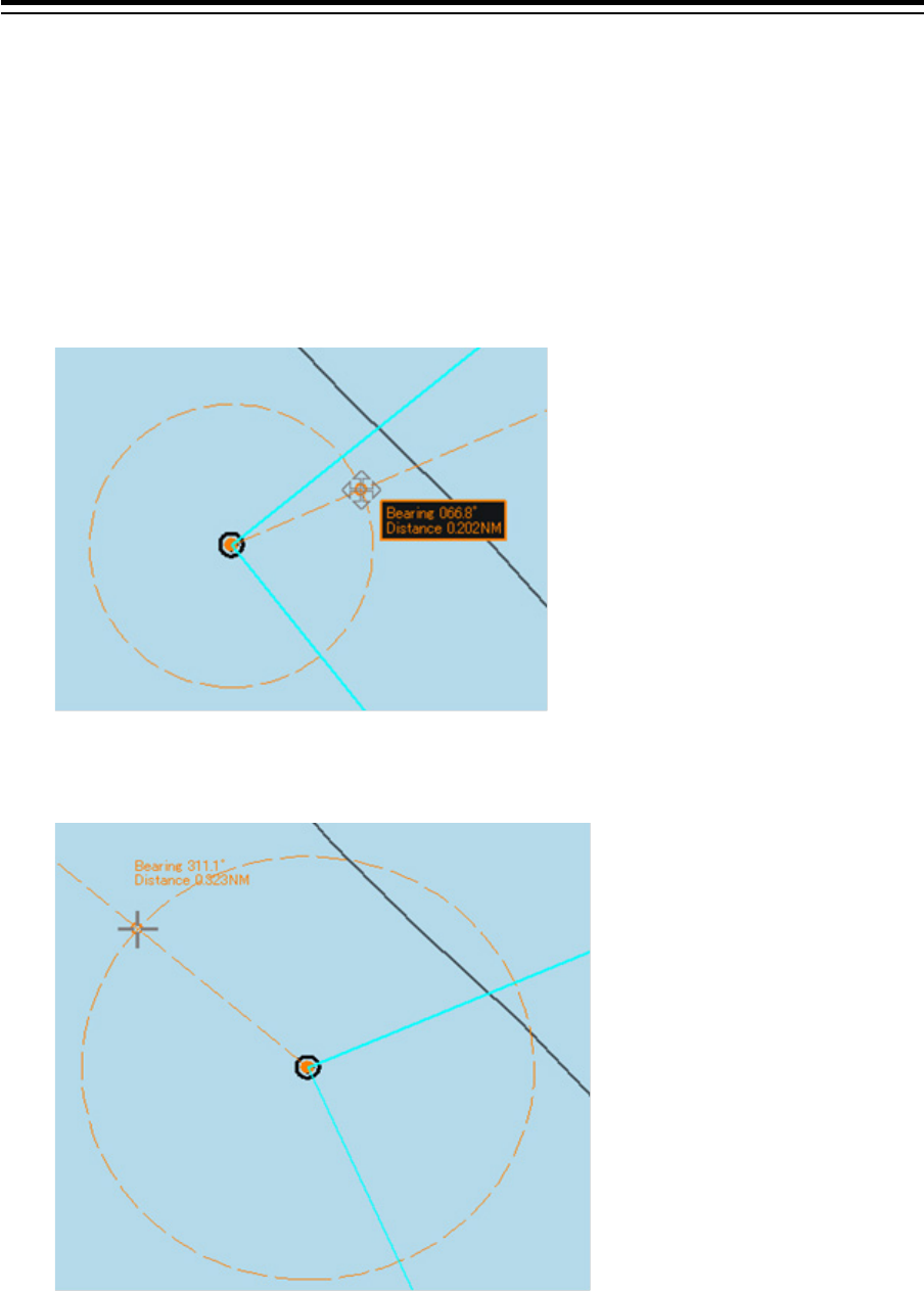
Section 4 Range and Bearing Measurement Methods 4-20
4.5.3.5 Manipulating EBL/VRM with [CCRP EBL/VRM] - [Make
EBL1/VRM1] or [Make EBL2/VRM2]
The manipulations of EBL1/VRM1 and EBL2/VRM2 are the same. Here, the manipulation of
EBL1/VRM1 is explained as an example.
1 Right-click on the screen to display the context menu.
2 Select [CCRP EBL/VRM] - [Make EBL1/VRM1] on the context menu.
EBL1 and VRM1 is displayed, and then the measurement starting point appears on own ship.
3 Move the cursor and click on at an arbitrary position.
The EBL1 bearing and the VRM1 range are fixed.

4-21 Section 4 Range and Bearing Measurement Methods
1
2
3
4
5
6
7
8
9
10
11
12
13
14
15
16
17
18
19
20
21
22
23
24
25
APP A
APP B
1
4.5.3.6 Manipulating EBL with [CCRP EBL/VRM] - [Make EBL1] or
[Make EBL2]
The manipulations of EBL1 and EBL2 are the same. Here, the manipulation of EBL1 is explained as an
example.
1 Right-click on the screen to display the context menu.
2 Select [CCRP EBL/VRM] - [Make EBL1] on the context menu.
EBL1 is displayed, and then the measurement starting point appears on own ship.
3 Move the cursor and click on at an arbitrary position.
The EBL1 bearing is fixed.
4.5.3.7 Manipulating VRM with [CCRP EBL/VRM] - [Make VRM1] or
[Make VRM2]
The manipulations of VRM1 and VRM2 are the same. Here, the manipulation of VRM1 is explained as
an example.
1 Right-click on the screen to display the context menu.
2 Select [CCRP EBL/VRM] - [Make VRM1] on the context menu.
VRM1 is displayed, and then the measurement starting point appears on own ship.
3 Move the cursor and click on at an arbitrary position.
The VRM1 range is fixed.
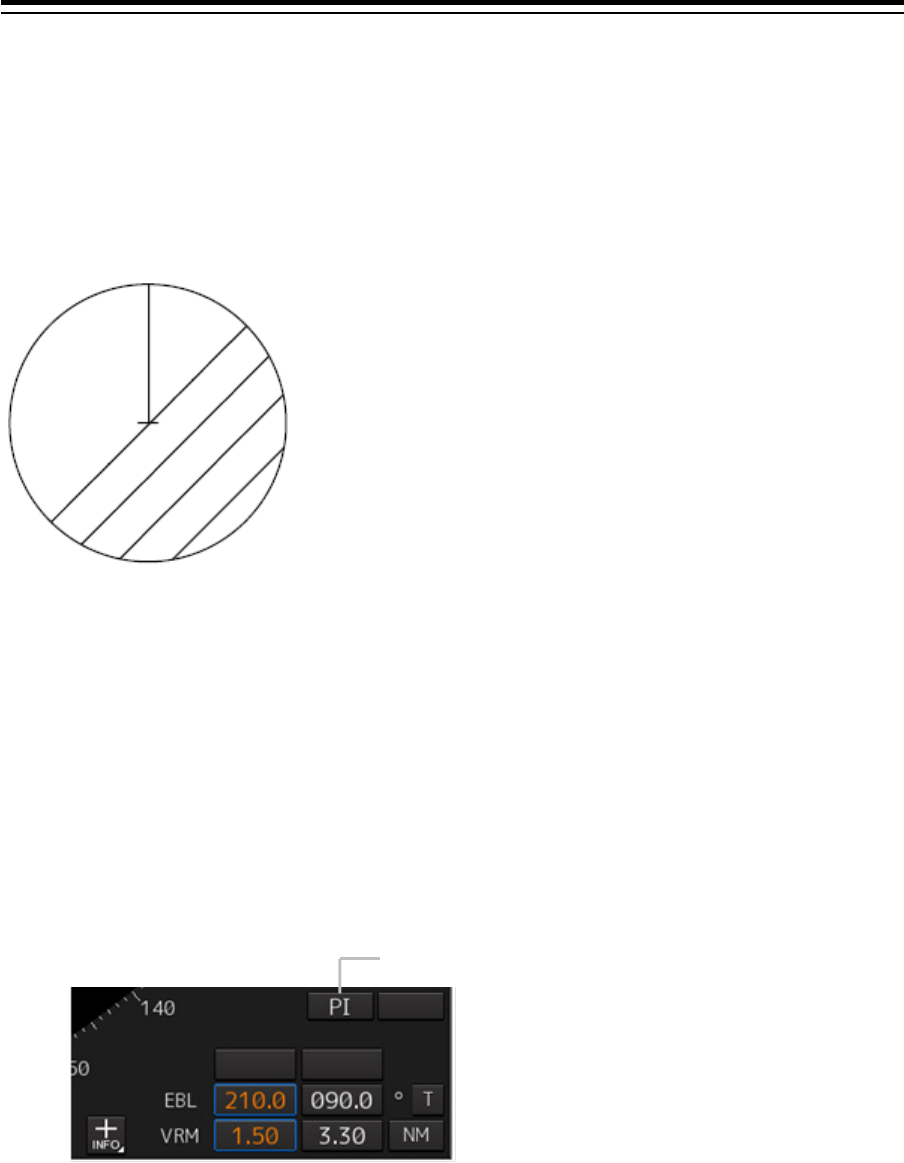
Section 4 Range and Bearing Measurement Methods 4-22
4.6 Using Parallel Index Lines (PI)
4.6.1 Description of a parallel index line
Parallel index lines (PI) refer to straight lines at equal interval that are displayed on the screen.
By using parallel index lines, complicated measurement is enabled relating to the bearing and the
range by using the own ship’s position as the reference point.
4.6.2 Displaying parallel index lines
4.6.2.1 Displaying parallel index lines in the trackball operation
unit
[RADAR]
1 Click on the [PI] button in Navigation Tools (measuring tool).
Operation when the [PI] button is clicked on:
• When the [PI] button is set to Off, PI is set to On and the "PI Menu" dialog is displayed.
• When the [PI] button is set to On and the "PI Menu" dialog is displayed, the "PI Menu" dialog
is closed. PI remains On.
• When the [PI] button is set to On and the "PI Menu" dialog is not displayed, PI is set to Off.
Example of Display
[PI] button
4-23 Section 4 Range and Bearing Measurement Methods
1
2
3
4
5
6
7
8
9
10
11
12
13
14
15
16
17
18
19
20
21
22
23
24
25
APP A
APP B
1
Memo
The "PI Menu" dialog can also be displayed by clicking on [Tool] - [PI] on the menu.
2 Set PI on the "PI Menu" dialog.
For the details of the "PI Menu" dialog, refer to "4.6.2.3 "Description of the "PI Menu" dialog".
The "PI Menu" dialog setting method varies depending on the PI operation mode. For the details,
refer to the descriptions of the operation mode in "4.6.3 Setting all the parallel index lines
concurrently (All mode)", "4.6.4 Setting parallel index lines individually (Individual mode)", "4.6.5
Displaying lines at equal interval on the left and right sides of the own ship’s position (Track
mode)", and "4.6.6 Displaying two intersecting lines (Equiangular mode)".
[ECDIS]
1 Click on the [Menu] button on the left toolbar.
The menu is displayed.
2 Click on [Tools] - [PI].
The "PI Menu" dialog box appears.
To clear parallel index lines:
1 Set the [Display for All Lines] button to Off by clicking on it.
The parallel index lines disappear.
4.6.2.2 Displaying parallel index lines in the keyboard operation
unit
1 Press the [PI] key.
Operation when the [PI] key is pressed:
- When the [Display for All Lines] button is set to Off, PI is set to On and the "PI Menu" dialog
box is displayed.
- When the [Display for All Lines] button is set to On and the "PI Menu" dialog is displayed, the
"PI Menu" dialog is closed. PI remains On.
- When the [Display for All Lines] button is set to On and the "PI Menu" dialog is not displayed,
PI is set to Off.
2 Set PI on the "PI Menu" dialog.
For the "PI Menu" dialog, refer to "4.6.2.3 Description of the "PI Menu" dialog".
The "PI Menu" dialog setting method varies according to the PI operation mode. For the details,
refer to the description of each operation mode, "4.6.3 Setting all the parallel index lines
concurrently (All mode)", "4.6.4 Setting parallel index lines individually (Individual mode)", "4.6.5
Displaying lines at equal interval on the left and right sides of the own ship’s position (Track
mode)", and "4.6.6 Displaying two intersecting lines (Equiangular mode)".
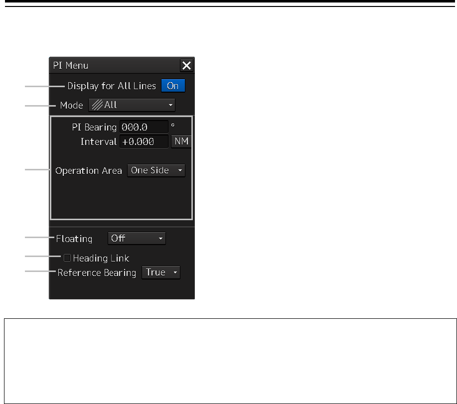
Section 4 Range and Bearing Measurement Methods 4-24
4.6.2.3 Description of the "PI Menu" dialog
Note
Parallel index lines can be operated by using the EBL/VRM dial of the keyboard operation unit only
while the "PI Menu" dialog is displayed. Even if the dialog is closed, the parallel index lines remain
displayed, however, the bearing and interval cannot be operated.
To reset the bearing and the interval, set by redisplaying the "PI Menu" dialog.
[1]
[2]
[3]
[4]
[5]
[6]
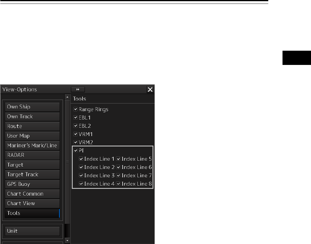
4-25 Section 4 Range and Bearing Measurement Methods
1
2
3
4
5
6
7
8
9
10
11
12
13
14
15
16
17
18
19
20
21
22
23
24
25
APP A
APP B
1
[1] [Display for All Lines] (Display for all PI lines) button
Use this button to switch display for all PI lines to ON/OFF.
The button ON/OFF state is maintained even if the dialog box is closed.
The parallel index lines that are displayed by setting the [Display for All Lines] button to On are those
that are selected on the [View-Options] dialog that is displayed by selecting [View] - [Options] - [Tools]
on the menu.
• When the operation mode is Individual and the [Display for All Lines] button is set to On, the
parallel index lines that were selected in the [View-Options] dialog (Index Line 1 to Index Line 8)
are displayed on the screen.
• When the operation mode is Track or Equiangular and the [Display for All Lines] button is set to
On, the parallel index lines that were selected in the [View-Option dialog] (Index Lines 1, 3, 5, and
7 correspond to groups 1, 2, 3, and 4 respectively) are displayed.
• When the operation mode is All, the line at the center of the screen becomes Index Line1 and the
parallel lines from the center to the outer section correspond to Index Line2, 3.... When [Operation
Area] is set to [Both Side], the parallel index lines forming pairs on opposite sides with each other
based on Index Line1 correspond to Index Line2, 3... towards the outer section.
[2] [Mode] (operation mode switching) combo box
Select an operation mode.
When the operation mode is selected, the dialog box of the selected operation mode is displayed.
For the details of the operation mode, refer to "4.6.3 Setting all the parallel index lines concurrently (All
mode)", "4.6.4 Setting parallel index lines individually (Individual mode)", "4.6.5 Displaying lines at
equal interval on the left and right sides of the own ship’s position (Track mode)" and "4.6.6 Displaying
two intersecting lines (Equiangular mode)".

Section 4 Range and Bearing Measurement Methods 4-26
[3] Parameter setting area by operation mode
Set parameters in each operation mode.
The settings differ depending on the operating mode.
Refer to "4.6.3 Setting all the parallel index lines concurrently (All mode)", "4.6.4 Setting parallel index
lines individually (Individual mode)", "4.6.5 Displaying lines at equal interval on the left and right sides
of the own ship’s position (Track mode)" and "4.6.6 Displaying two intersecting lines (Equiangular
mode)".
[4] [Floating] combo box
Move the center of the parallel index line.
Select the Floating mode from the list.
• [Off]: Sets the starting point of the parallel index line to the CCRP position.
• [Screen Fix]: Moves the center of the parallel index line and fixes it on the screen.
• [L/L Fix]: Moves the center of the parallel index line and fixes it based on the latitude and
longitude.
(Connection of a navigation unit is required.)
[5] [Heading Link] (Heading link setting)
Set whether the parallel index line is linked to the ship’s heading.
• When this item is checked, the parallel index line is linked to the ship’s heading.
• When this item is unchecked, the parallel index line is not linked to the ship’s heading.
Different values can be set for the angle of the parallel index lines when this item is checked and the
angle of the parallel index lines when the item is unchecked.
[6] [Reference Bearing] (Reference bearing selection)
Set a reference bearing of the bearing value display of the parallel index line.
• [True]: Displays in true bearing (based on the North).
• HL: Displays in the heading line reference.
• Index Line 1 to Index Line 8: Displays by using the Index Line as the reference. (Only when
the operation mode is "Individual")
• Group 1 to Group 4: Displays by using the Group as the reference. (Only when the operation
mode is "Track")
Memo
[Reference Bearing] (reference bearing selection) is not displayed in Equiangular mode as the
operation mode.

4-27 Section 4 Range and Bearing Measurement Methods
1
2
3
4
5
6
7
8
9
10
11
12
13
14
15
16
17
18
19
20
21
22
23
24
25
APP A
APP B
1
Switching the Floating mode
When [Screen Fix] or [L/L Fix] is selected in switching the Floating mode, the cursor mode changes.
Note
When the operation mode is [All] and the reference point that is set in [L/L Fix] moves to the
position outside of the PPI circle, the floating mode is set to Off and the own ship’s position
becomes the reference point.
• When the screen is clicked on, the fixed position or the coordinates on the screen are determined,
and the cursor is changed to the normal cursor.
• When [Screen Fix] or [L/L Fix] is re-selected after the determination, the cursor changes to the
center selection cursor for parallel index lines.
• When PI is created with View2 of multi-view after selecting [Screen Fix], PI terminates after
termination of the multi-view function.
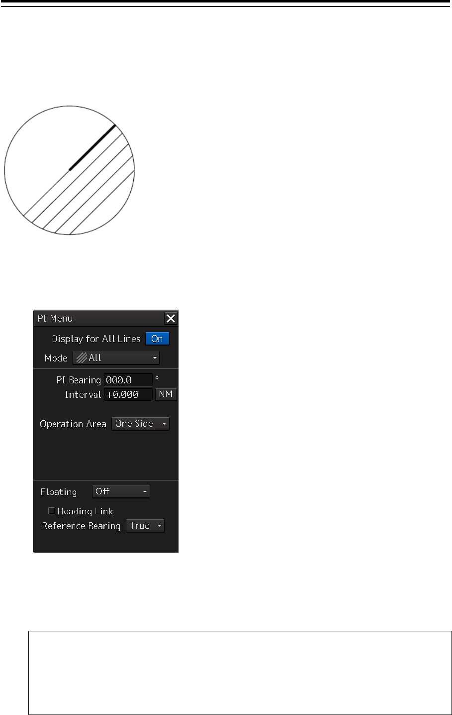
Section 4 Range and Bearing Measurement Methods 4-28
4.6.3 Setting all the parallel index lines
concurrently (All mode)
When the operation mode is set to [All], all the parallel index lines are operated concurrently. All the
lines are in parallel.
1 Select [All] from the [Mode] (operation mode) combo box.
2 Enter a direction of the parallel index lines in [PI Bearing] (parallel index line bearing
adjustment).
The setting is applied to the bearings of all the parallel index lines.
Memo
The bearing can also be adjusted by turning the [EBL
] dial clockwise/counterclockwise.
When the dial is turned clockwise, the bearing is adjusted in the plus direction, and when
the dial is turned counterclockwise, the bearing is adjusted in the minus direction.
The set value is displayed in the input box.
Display Example
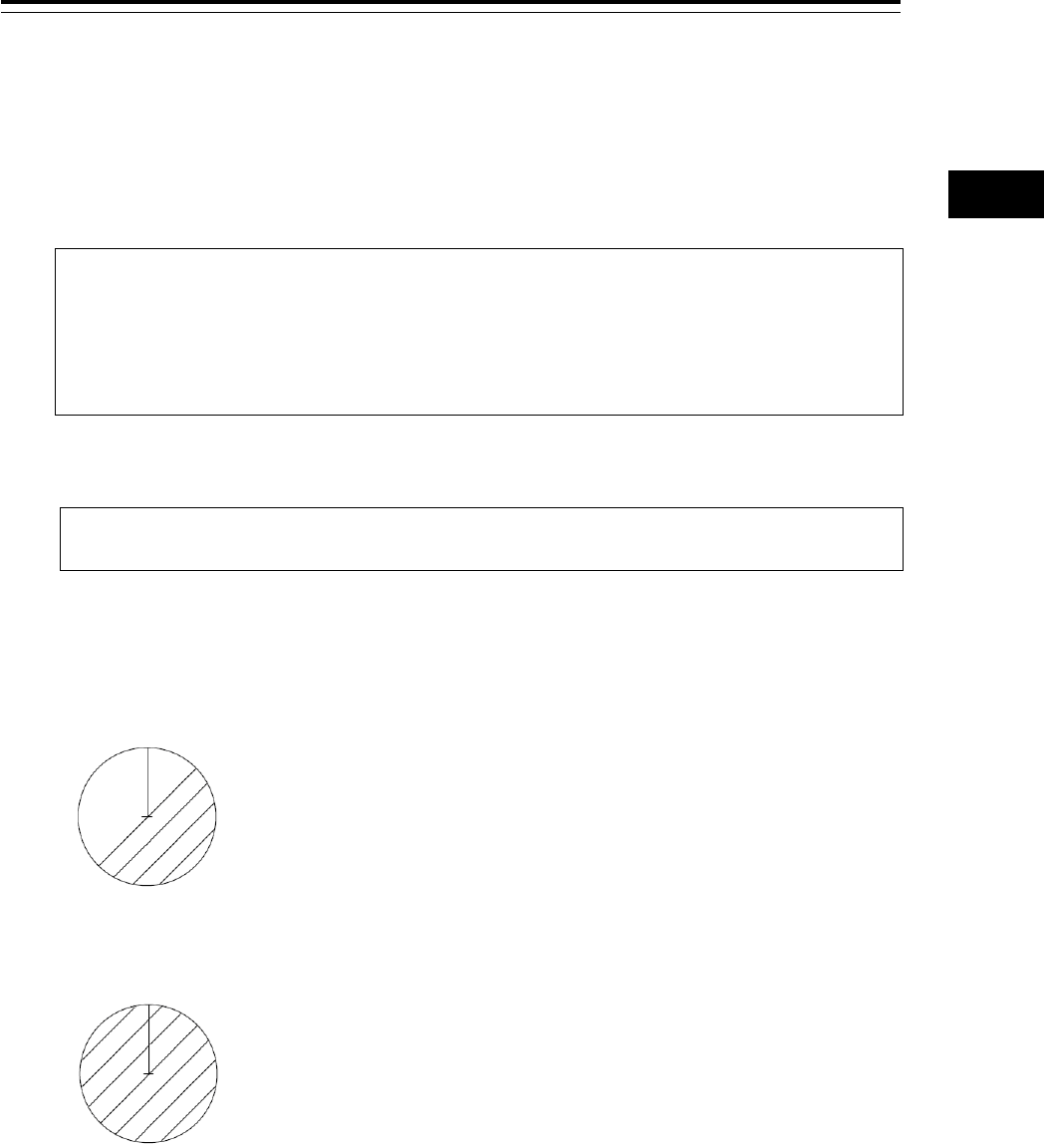
4-29 Section 4 Range and Bearing Measurement Methods
1
2
3
4
5
6
7
8
9
10
11
12
13
14
15
16
17
18
19
20
21
22
23
24
25
APP A
APP B
1
3 Enter a display interval of the parallel index lines in [Interval] (parallel index line
interval adjustment).
The setting is applied to all the lines.
The input range is the PPI radius when PPI is used as the center for the lines and double the PPI
radius when the PPI is not used as the center. (In the case of ECDIS, the input range is the
length of the diagonal line of the screen.)
Memo
The bearing can also be adjus
ted by turning the [VRM] dial clockwise/counterclockwise.
When the dial is turned clockwise, the bearing is adjusted in the plus direction and when the
dial is turned counterclockwise, the bearing is adjusted in the minus direction.
The set value is displayed in the input box.
Whenever the unit display switching button on the right side of [Interval] is clicked on, the unit
(NM/km/sm) of the value displayed is switched.
Memo
NM denotes nautical mile, sm denotes statute mile, and km denotes kilometer.
4 Select the area for displaying the parallel index line from the [Operation Area]
(operation area selection) combo box.
When [One Side] is selected, 8 parallel index lines are displayed on one side of the reference
point of own ship or the point set arbitrarily.
When [Both Side] is selected, 15 parallel index lines are displayed on both sides of the reference
point of own ship or the point set arbitrarily.
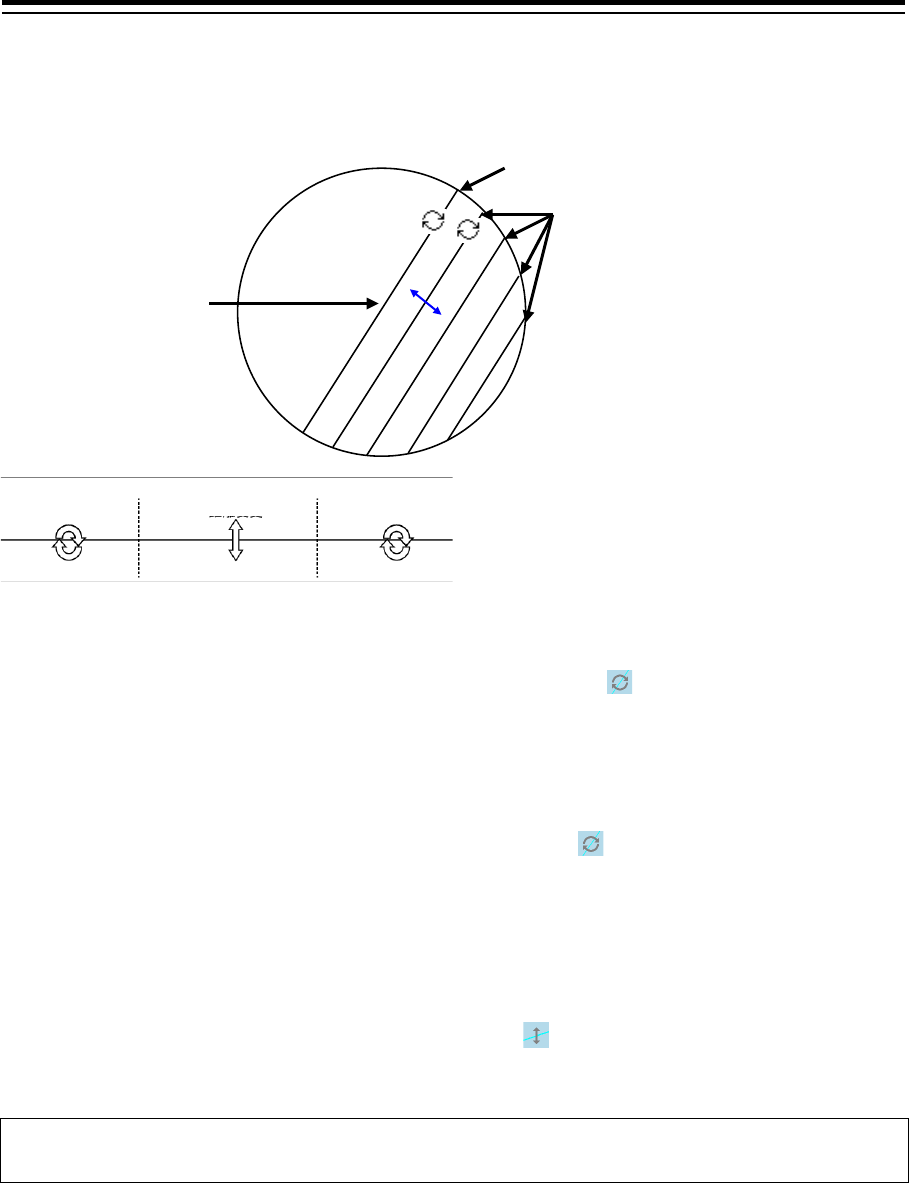
Section 4 Range and Bearing Measurement Methods 4-30
4.6.3.1 Changing the bearing/interval of parallel index lines in the
trackball operation unit (All mode)
[Changing the bearing with index line 1]
When index line 1 is clicked on, the shape of the cursor changes to .
All the index lines rotate centering on the index line reference position (starting point).
[Changing the bearing at a clickable trisectional end segment position of index lines 2 to 8]
When one of the index lines 2 to 8 is divided into three equal segments and the mouse button is clicked
on both ends of the line segments, the cursor shape changes to .
Index lines 2 to 8 move, forming a circle centering on the reference position while the index line
reference position (starting point) is fixed.
[Changing the interval at a clickable trisectional center segment position of index lines 2 to 8]
When one of the index lines 2 to 8 is divided into three equal segments and the mouse button is clicked
on the middle line segments, the cursor shape changes to .
Index lines 2 to 8 move in parallel to index line 1.
Memo
If a clickable segment is 2 cm or less, the change of interval mode is always activated.
Change of
angle
Change of
angle
Change of
angle
Dividing the line segment that can be clicked into 3 equal sections
CCRP is the
reference point
Index line 1
Index line 2 to 8
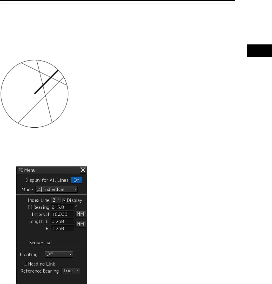
4-31 Section 4 Range and Bearing Measurement Methods
1
2
3
4
5
6
7
8
9
10
11
12
13
14
15
16
17
18
19
20
21
22
23
24
25
APP A
APP B
1
4.6.4 Setting parallel index lines individually
(Individual mode)
By setting the operation mode to [Individual], the bearing and the interval of parallel index lines can be
set individually.
1 Select [Individual] from the [Mode] (operation mode) combo box.
2 Select a parallel index line (1 to 8) to be set from the [Index Line] (parallel index line
selection) combo box
3 Select [Display].
The selected parallel index line is displayed.
4 Enter the bearing of the parallel index line in [PI Bearing] (parallel index line bearing
adjustment).
Display Example
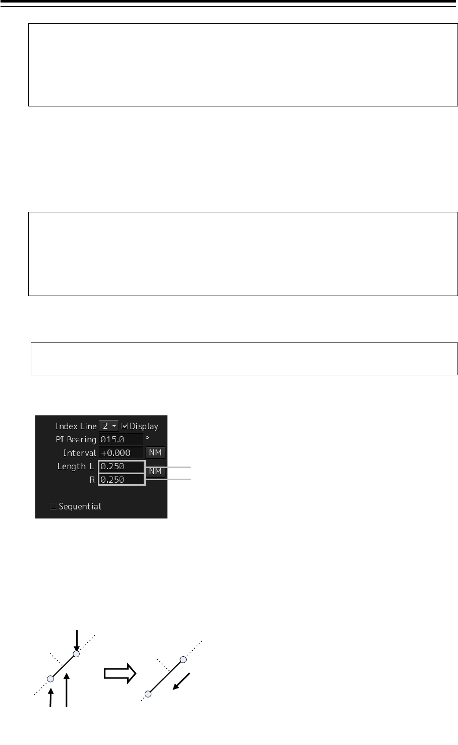
Section 4 Range and Bearing Measurement Methods 4-32
Memo
The bearing can also be adjusted by turning the [EBL] dial clockwise/counterclockwise.
When the dial is turned clockwise, the bearing is adjusted in the plus direction, and when
the dial is turned counterclockwise, the bearing is adjusted in the minus direction.
The set value is displayed in the input box.
5 Enter the interval of the parallel index line in [Intereval] (parallel index line interval
adjustment).)
The input range is the PPI radius when PPI is used as the center for the lines and double the PPI
radius when the PPI is not used as the center. (In the case of ECDIS, the input range is the
length of the diagonal line of the screen.)
Memo
The bearing can
also be adjusted by turning the [VRM] dial clockwise/counterclockwise.
When the dial is turned clockwise, the bearing is adjusted in the plus direction and when the
dial is turned counterclockwise, the bearing is adjusted in the minus direction.
The set value is displayed in the input box.
Whenever the unit display switching button on the right side of [Interval] is clicked on, the unit
(NM/km/sm) of the numeric value that is displayed is switched.
Memo
NM denotes nautical mile, sm denotes statute mile, and km denotes kilometer.
6 Set [Length] (adjustment of parallel index line length).
Adjust the length of the parallel index line by changing the positions of endpoint 1 and endpoint 2.
• Define endpoint 1 as the point on the left side when PI center is viewed from the own ship and
endpoint 2 as the point on the right side.
Endpoint 2
Endpoint 1
Endpoint 2
Endpoint 1
Change the length of endpoint 2
Center of PI

4-33 Section 4 Range and Bearing Measurement Methods
1
2
3
4
5
6
7
8
9
10
11
12
13
14
15
16
17
18
19
20
21
22
23
24
25
APP A
APP B
1
• Set the mode to the endpoint change mode by pressing the [VRM] dial and turn the [VRM] dial to
change the position of an endpoint.
Clockwise: + (Direction from the center of PI to outside)
Counterclockwise: - (Direction towards the center of PI)
The input range is as follows.
• The minimum length of a parallel index line from the left end to the right end is 2 cm.
• The maximum length is double the PPI radius.
Memo
A negative value can also be set for [Length].
• In the case of the left end, the left direction from the center becomes a positive value and the
right direction from the center becomes a negative value.
• In the case of the right end, the right direction from the center becomes a positive value and the
left direction from the center becomes a negative value.
Whenever the unit display switching button on the right side of [length] is clicked on, the unit
(NM/km/sm) of the numeric value that is displayed is switched.
Memo
NM denotes nautical mile, sm denotes statute mile, and km denotes kilometer.
Setting parallel index lines consecutively
When [Sequential] is checked and [Screen Fix] or [L/L Fix] is selected at floating mode switching, the
parallel index lines to be set are changed in the sequence of Index Line1→2→•••→8→1••• and setting
can be performed consecutively.
Note
The index lines that are set to be hidden by selecting [View] - [Options] - [Tools] on the menu are
skipped during operation.
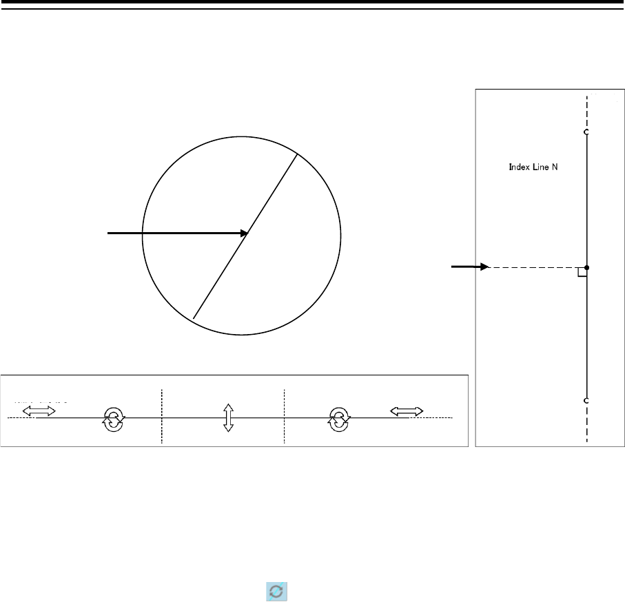
Section 4 Range and Bearing Measurement Methods 4-34
4.6.4.1 Changing the bearing/interval/end point of parallel index
lines in the trackball operation unit (Individual mode)
[Changing the bearing at a clickable trisectional segment position on both sides]
1 Place the cursor on the lines on both sides of the lines that were created by dividing
one of the index lines 1 to 8, which can be clicked, into 3 equal sections and click the
button.
The shape of the cursor changes to and when the mouse button is clicked, the bearing of
the parallel index lines can be changed.
2 Move the cursor to the bearing to be set.
The bearing of the parallel index lines changes together with the cursor.
3 Click the mouse button.
The parallel index lines are fixed.
Reference Point
Consistent Common
Reference Point (CCRP)
End point 1
Supplementary line
Reference point on the line
Supplementary line
Supplementary line
End point 2
Change of end
point position Change of angle
Change of distance
Change of angle
Change of end
point position
Dividing the line segment that can be clicked into 3 equal sections
End points 1 and 2
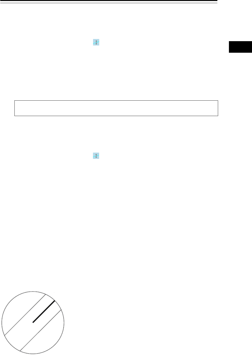
4-35 Section 4 Range and Bearing Measurement Methods
1
2
3
4
5
6
7
8
9
10
11
12
13
14
15
16
17
18
19
20
21
22
23
24
25
APP A
APP B
1
[Changing the distance at a clickable trisectional middle position]
1 Place the cursor on the middle line of the lines that were created by dividing one of the
index lines 1 to 8, which can be clicked, into 3 equal sections and click the button.
The shape of the cursor changes to and when the mouse button is clicked, the interval of
the parallel index lines can be changed.
2 Move the cursor to the interval to be set.
The interval of the parallel index lines changes together with the cursor.
3 Click the mouse button.
The parallel index lines are fixed.
Memo
If a clickable segment is 2 cm or less, the change of interval mode is always activated.
[Changing the positons of end points 1 and 2]
1 Set the cursor on the broken-line display section on the end point side to be moved on
one of the index lines 1 to 8.
The shape of the cursor changes to and when the mouse button is clicked, the position of
end point 1 or end point 2 can be changed.
2 Move the cursor to the bearing to be set.
The position of end point 1 or 2 changes together with the cursor.
3 Click the mouse button.
The position of end point 1 or 2 is fixed.
4.6.5 Displaying lines at equal interval on the left
and right sides of the own ship’s position
(Track mode)
When the operation mode is set to [Track], lines are displayed on both the left and right sides at equal
intervals.
Display Example
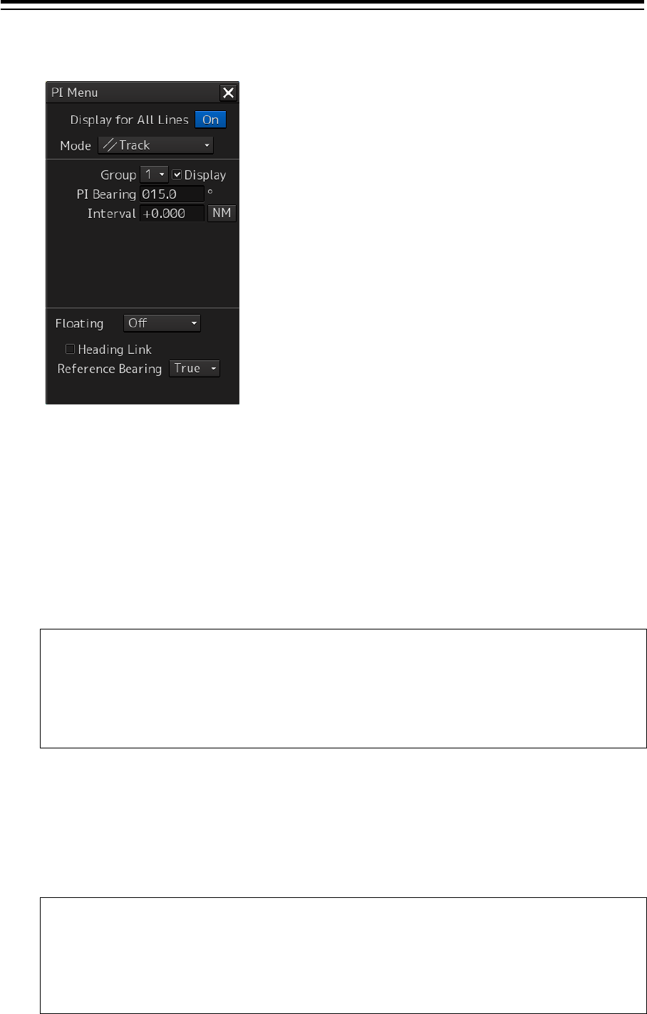
Section 4 Range and Bearing Measurement Methods 4-36
1 Select [Track] from the [Mode] (operation mode) combo box.
2 Select a parallel line cursor group (1 to 4) from the [Group] (parallel line cursor group)
combo box.
Since in [Track] mode, parallel index lines always form pairs, set in group units.
3 Select [Display].
The selected parallel line cursor group is displayed.
4 Enter the bearing of the parallel index line group in [PI Bearing] (parallel index line
bearing adjustment).
Memo
The bearing can also be adjusted by turning the [EBL] dial clockwise/counterclockwise.
When the dial is turned clockwise, the bearing is adjusted in the plus direction, and when
the dial is turned counterclockwise, the bearing is adjusted in the minus direction.
The set value is displayed in the input box.
5 Enter the interval of the parallel index line group in [Interval] (parallel index line group
interval adjustment).
The input range is the PPI radius when PPI is used as the center for the lines and double the PPI
radius when the PPI is not used as the center. (In the case of ECDIS, the input range is the
length of the diagonal line of the screen.)
Memo
The bearing can also be adjusted by turning the [VRM] dial clockwise/counterclockwise.
When the dial is turned clockwise, the bearing is adjusted in the plus direction and when the
dial is turned anti-clockwise, the bearing is adjusted in the minus direction.
The set value is displayed in the input box.
Whenever the unit display switching button on the right side of [Interval] is clicked on, the unit
(NM/km/sm) of the numeric value that is displayed is switched.
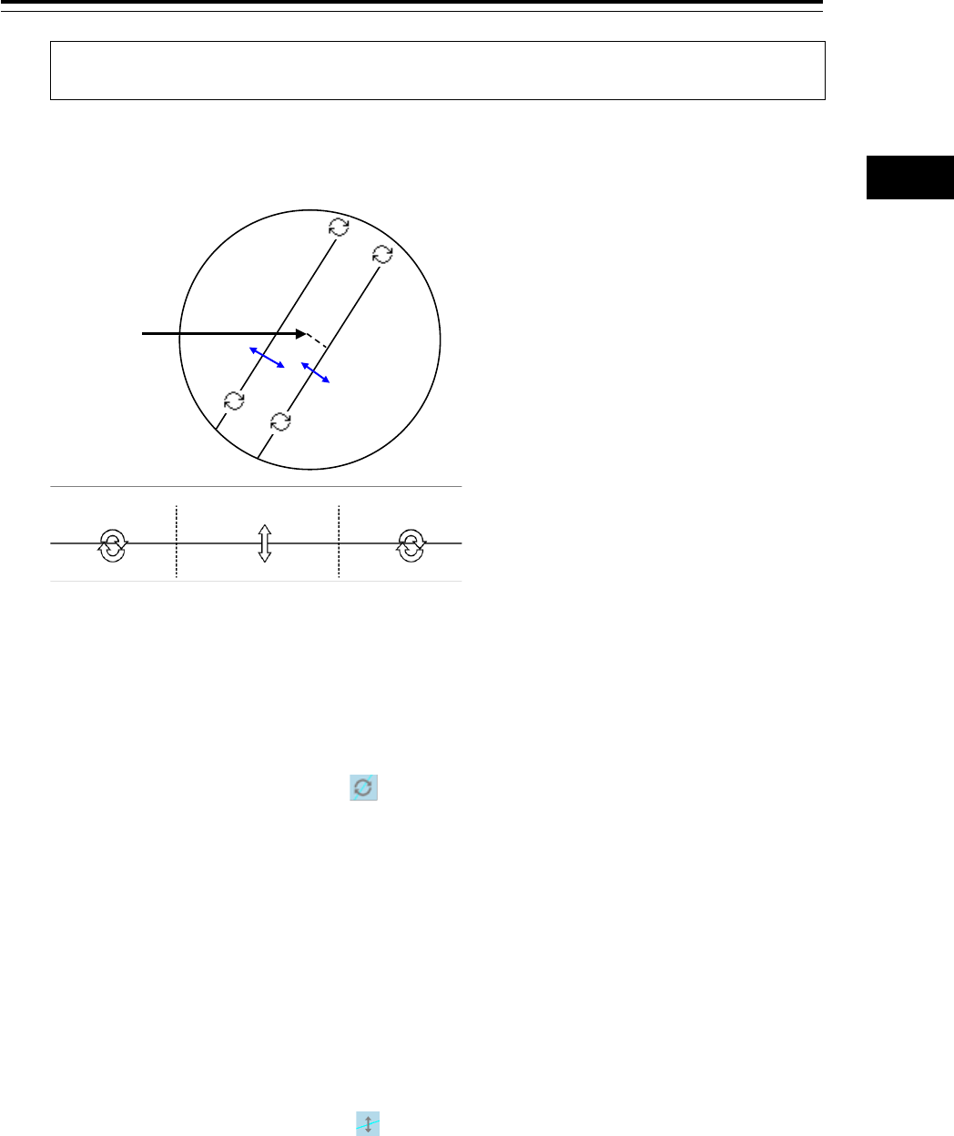
4-37 Section 4 Range and Bearing Measurement Methods
1
2
3
4
5
6
7
8
9
10
11
12
13
14
15
16
17
18
19
20
21
22
23
24
25
APP A
APP B
1
Memo
NM denotes nautical mile, sm denotes statute mile, and km denotes kilometer.
4.6.5.1 Changing the bearing/interval of parallel index lines with
the trackball (Track mode)
[Changing the bearing at a clickable trisectional end segment position]
1 Place the cursor on the lines on both sides of the lines that were created by dividing
one of the index lines 1 to 8, which can be clicked, into 3 equal sections and click the
button.
The shape of the cursor changes to and when the mouse button is clicked, the bearing of
the parallel index lines can be changed.
2 Move the cursor to the bearing to be set.
The bearing of the parallel index lines changes together with the cursor.
3 Click the mouse button.
The parallel index lines are fixed.
[Changing the distance at a clickable trisectional middle position]
1 Place the cursor on the middle line of the lines that were created by dividing one of the
index lines 1 to 8, which can be clicked, into 3 equal sections and click the button.
The shape of the cursor changes to and when the mouse button is clicked, the interval of
the parallel index lines can be changed.
2 Move the cursor to the interval to be set.
The interval of the parallel index lines changes together with the cursor.
3 Click the mouse button.
The parallel index lines are fixed.
CCRP is the
reference point
Change of
angle
Change of
angle
Change of
angle
Dividing the line segment that can be clicked into 3 equal sections
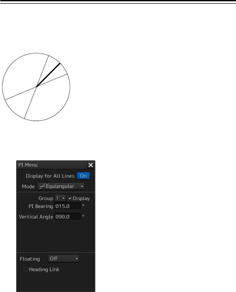
Section 4 Range and Bearing Measurement Methods 4-38
4.6.6 Displaying two intersecting lines
(Equiangular mode)
When the operation mode is set to [Equiangular], two intersecting lines are displayed.
1 Select [Equiangular] from the [Mode] (operation mode) combo box.
2 Select a parallel index line group (1 to 4) from the [Group] (parallel index line group).
Since parallel index lines form pairs in [Equiangular] mode, set in group units.
3 Select [Display].
The selected parallel line cursor group is displayed.
4 Enter the bearing of the parallel index line group in [PI Bearing] (parallel index line
bearing adjustment).
Display Example
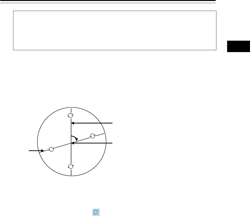
4-39 Section 4 Range and Bearing Measurement Methods
1
2
3
4
5
6
7
8
9
10
11
12
13
14
15
16
17
18
19
20
21
22
23
24
25
APP A
APP B
1
Memo
The bearing can also be adjusted by turning the [EBL] dial clockwise/counterclockwise.
When the dial is turned clockwise, the bearing is adjusted in the plus direction, and when
the dial is turned counterclockwise, the bearing is adjusted in the minus direction.
The set value is displayed in the input box.
5 Enter the vertical angle of the parallel index line group in [Vertical angle] (parallel index
line vertical angle adjustment).
4.6.6.1 Changing the bearing of two intersecting lines in the
trackball operation unit (Equiangular mode)
[Changing the bearing of index lines 1 to 8]
1 Place the cursor on index lines 1 to 8 and click the mouse button.
The shape of the cursor changes to and when the mouse button is clicked, the bearing of
the two intersecting lines can be changed.
2 Move the cursor to the bearing to be set.
The bearing of the two intersecting lines changes together with the cursor.
3 Click the mouse button.
The two intersecting lines are fixed.
Consistent Common
Reference Point (CCRP)
Measureme
nt number
Reference line
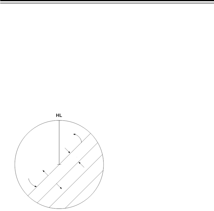
Section 4 Range and Bearing Measurement Methods 4-40
4.6.7 Setting parallel index lines in the keyboard
operation unit
The bearing and interval of parallel index lines can be set with the [EBL] and [VRM] dials.
1 Press the [PI] key to display the [PI Menu] dialog box.
2 By turning the [EBL] dial, set up bearing.
Turning the [EBL] dial to the right changes the bearing of parallel index lines in the right bearing
[1] and turning it to the left changes in the left bearing [2].
3 By turning the [VRM] dial, set up the interval of parallel index lines.
Turning the [VRM] dial to the left narrows the interval of parallel index lines [3] and turning it to
the right widens the interval [4].
4 Press the [PI] key to close the [PI Menu] dialog box.
The parallel index lines are fixed.
The operation and motion of the parallel index differ depending on the motion mode in the [PI Menu]
dialog.
4.6.7.1 Operation in All mode
[Operating the [EBL] dial]
By using the [EBL] dial, the bearing of the index lines can be changed.
[Operating the [VRM] dial]
By using the [VRM] dial, the interval of the index lines can be changed.
[1]
[2]
[3]
[4]
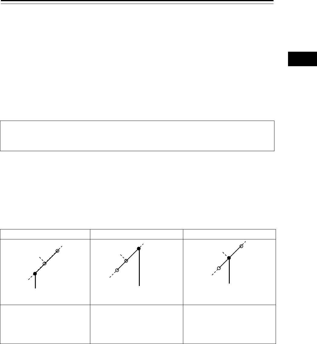
4-41 Section 4 Range and Bearing Measurement Methods
1
2
3
4
5
6
7
8
9
10
11
12
13
14
15
16
17
18
19
20
21
22
23
24
25
APP A
APP B
1
4.6.7.2 Operation in Individual mode
In Individual mode, the index line that is selected in the [Index Line] combo box is operated.
[Using the [EBL] dial]
By using the [EBL] dial, the bearing of the index line can be changed.
Setting parallel index lines consecutively by using the [EBL] dial
When [Sequential] is checked, the floating mode is set. When [Screen Fix] or [L/L Fix] is selected, the
parallel index line to be set is switched in the sequence of Index Line1→2→•••→8→1•••, enabling
consecutive setting.
Note
The index lines that are set to be hidden by selecting [View] - [Options] - [Tools] on the menu are
skipped during operation.
[Operating the [VRM] dial]
By using the [VRM] dial, the interval of the index lines can be changed.
The reference point for changing the interval can be an end point 1 or 2 of the index line or the
reference point on the line.
Whenever the [VRM] dial is pressed, the reference point is selected in the sequence of "end point
1→end point 2→reference point on the line→•••"
End point 1
End point 2
Reference point on the line
As a result of the selection, the
distance from the reference
point to the end point 1 on the
line changes.
As a result of the selection, the
distance from the reference
point to the end point 2 on the
line changes.
As a result of selection, the
interval from the reference point
to the index line changes.
4.6.7.3 Operation in Track mode
The index lines of the group that is selected in [Group] combo box are operated in Track mode.
[Operating the [EBL] dial]
By using the [EBL] dial, the bearing of the index lines can be changed.
[Operating the [VRM] dial]
By using the [VRM] dial, the interval of the index lines can be changed.
End point 1
End point 2
Reference point on the line

Section 4 Range and Bearing Measurement Methods 4-42
4.6.7.4 Operation in Equiangular mode
The index lines of the group that is selected in [Group] combo box are operated in Equiangular mode.
[Operating the [EBL] dial]
By pressing the [EBL] dial, the "Group reference line (PI Bearing)" and the "Group measurement line"
can be set.
Whenever the [EBL] dial is pressed, the "Group reference line (PI Bearing)" and the "Group
measurement line" are selected alternately.
Memo
A measurement line can be set across the reference line. (When a measurement line is set across
the reference line by rotating the dial in the minus direction, the measured bearing data changes
as 0°→359.9°.)
When the reference line is set by using the EBL dial, the value of the measured bearing data is
maintained and the measurement line follows concurrently.
[Operation the [VRM] dial]
In Equiangular mode, the [VRM] dial is disabled.
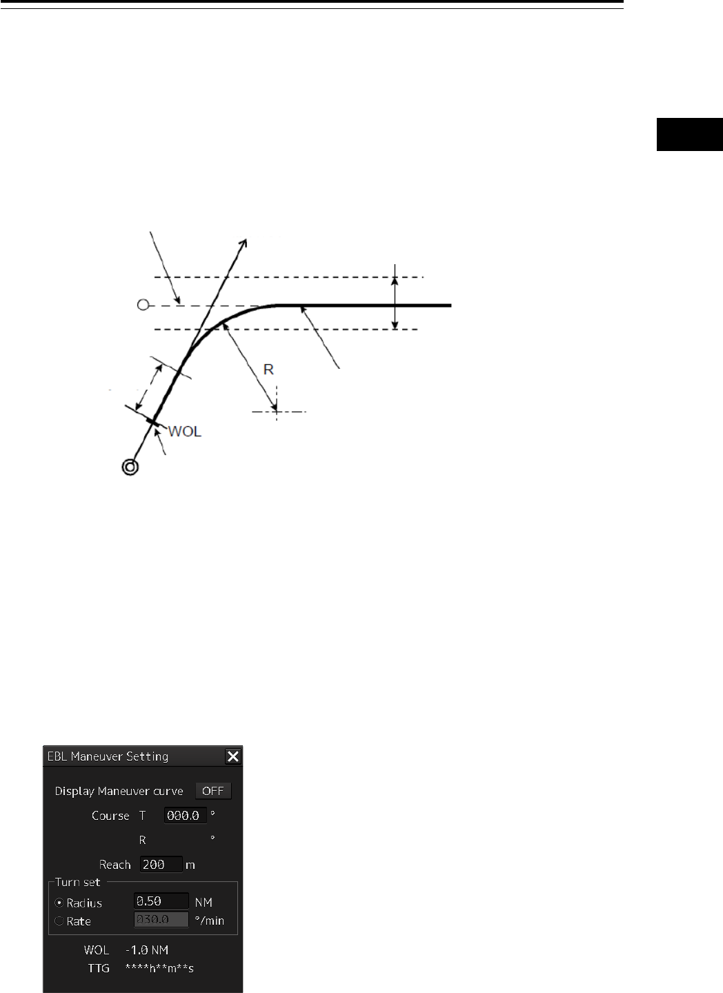
4-43 Section 4 Range and Bearing Measurement Methods
1
2
3
4
5
6
7
8
9
10
11
12
13
14
15
16
17
18
19
20
21
22
23
24
25
APP A
APP B
1
4.7 Using the EBL Maneuver
The EBL Maneuver is the function that displays a predictable track when own ship is turned under
certain conditions.
By displaying a maneuver curve that has been drawn by taking safety into consideration, it can be
used as the guideline for turning.
4.7.1 Displaying the EBL Maneuver Setting dialog
box
1 Click on the [Menu] bar on the left toolbar.
The menu is displayed.
2 Click on the [Tools] - [EBL Maneuver] button on the menu.
The "EBL Maneuver Setting" dialog box appears.
Supplemental line
Ship’s heading
Scheduled route
Own
ship’s
position
Reach
Maneuver curve
(Wheel Over Line)
WOL line
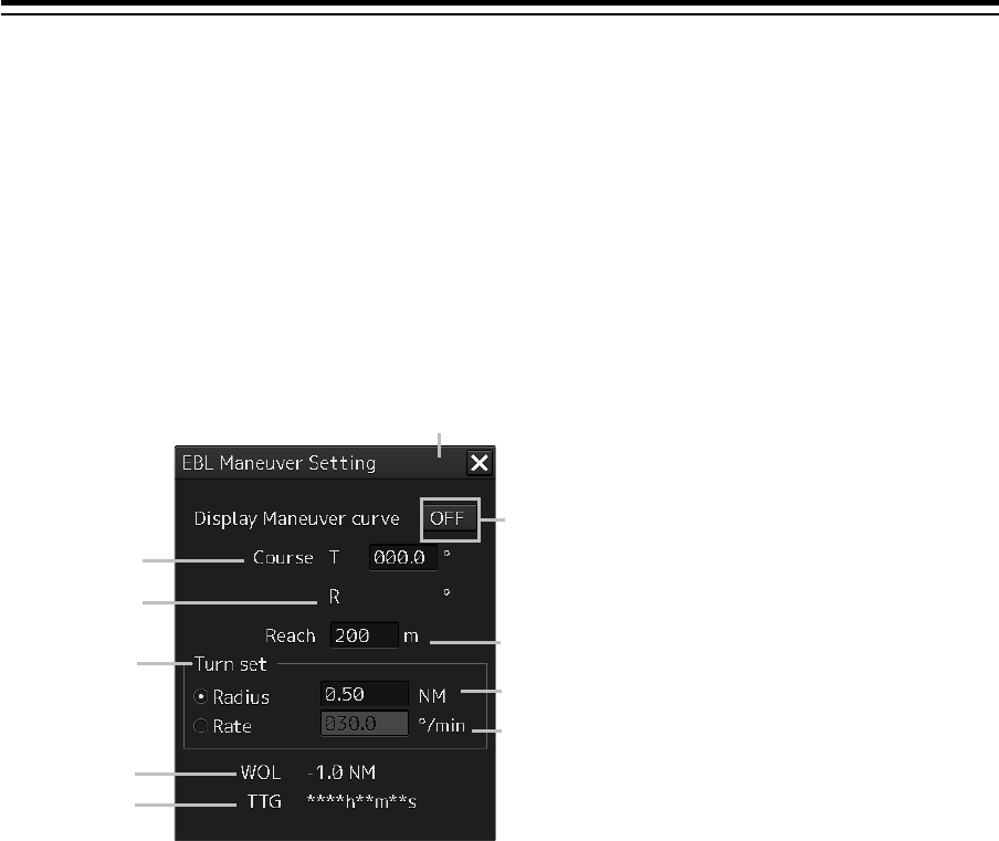
Section 4 Range and Bearing Measurement Methods 4-44
4.7.2 Clearing the display of maneuver curve
1 Click on the [Display Maneuver curve] button.
The [Display Maneuver curve] button display is set to [OFF] and the maneuver curve is cleared
from the screen.
4.7.3 Setting the creation conditions of the EBL
Maneuver
[1] [X] button
Use this button to close the "EBL Maneuver" dialog box.
[2] [Display Maneuver curve] (Maneuver curve display) button
When this button is set to ON, the cursor mode changes to the maneuver curve creation mode.
[3] [Course T] (Bearing of the acquisition line (true bearing))
The bearing of the acquisition line is displayed in true bearing. The line can also be set.
The input range is from 0.0 to 359.9°.
[4] [Course R] (Bearing of the acquisition line (relative bearing))
The bearing of the acquisition line is displayed in relative bearing.
[5] [Reach] (Distance from steering to turning)
The distance (reach) from steering to turning is displayed. The line can also be set.
The input range is from 0 to 2000 m (integer value).
[6] [Turn set] (Turning mode)
Select a turning mode from either [Radius] (constant turn radius) or [Rate] (constant turn rate).
[7] [Radius] (Constant turn radius)
Set a constant turn radius to be used for the Radius turn mode.
The input range is from 0.10 to 9.99NM.
[2]
[7]
[8]
[4]
[6]
[10]
[9]
[5]
[1]
[3]
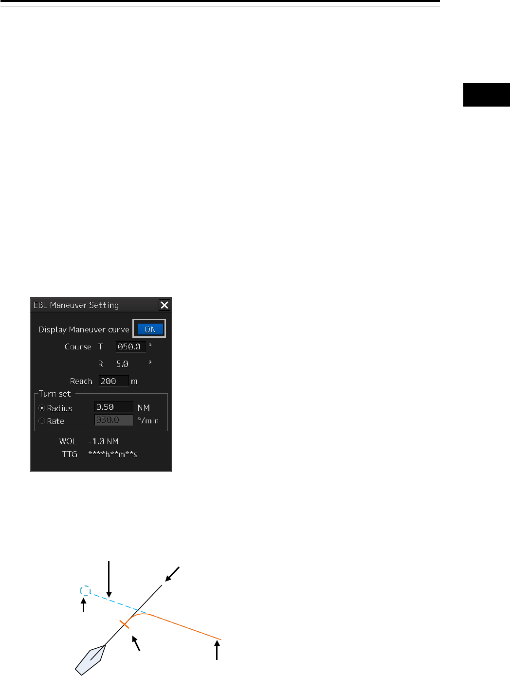
4-45 Section 4 Range and Bearing Measurement Methods
1
2
3
4
5
6
7
8
9
10
11
12
13
14
15
16
17
18
19
20
21
22
23
24
25
APP A
APP B
1
[8] [Rate] (Constant turn rate)
Set a constant turn speed to be used in Rate turn mode.
The input range is from 20.0 to 720°/min.
[9] [WOL] (Distance to WOL)
The distance up to WOL is displayed.
[10] [TTG] (Expected traveling time to reach WOL)
The expected traveling time to reach WOL is displayed.
When the ship’s speed is 0 or the speed information of the own ship is invalid and the TTG value is
invalid, "**h**m**s" is displayed.
4.7.4 Creating an EBL maneuver curve
1 Set the function to [ON] by clicking on the [Display Maneuver curve] (EBL maneuver
curve) button.
A supplemental line, a maneuver curve, and a WOL for creating a maneuver curve are displayed
and the maneuver curve creation mode is set.
The bearing of the supplementary line can be changed by turning the EBL dial during creation of
a maneuver curve.
Supplemental line
Heading line
WOL
Maneuver curve
Starting position of
supplemental line
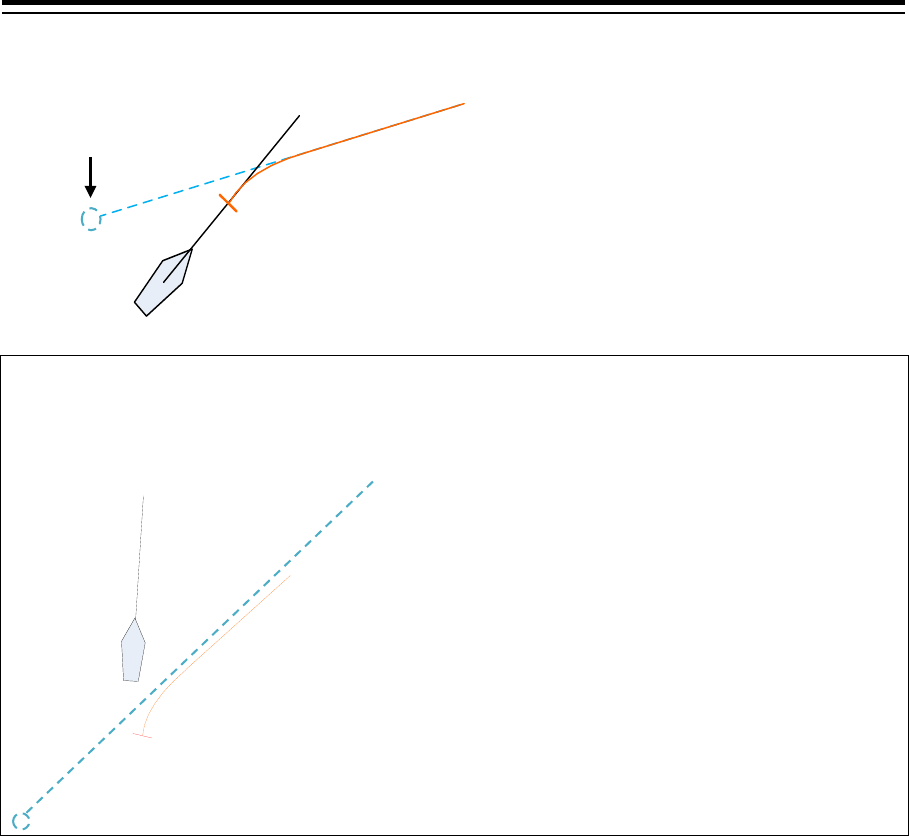
Section 4 Range and Bearing Measurement Methods 4-46
2 Determine a supplemental line starting position by clicking.
Note
When the WOL
position is behind the own ship, the color of WOL changes to red and the
supplemental line starting point can no longer be determined by clicking on the point.
Cancelling the creation of maneuver curve
By clicking the right-button in maneuver curve creation mode, the creation can be cancelled.
Click
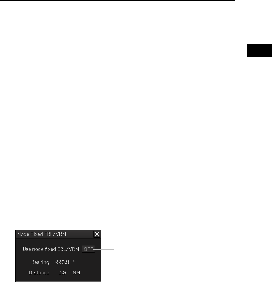
4-47 Section 4 Range and Bearing Measurement Methods
1
2
3
4
5
6
7
8
9
10
11
12
13
14
15
16
17
18
19
20
21
22
23
24
25
APP A
APP B
1
4.8 Connecting Own Ship and the
Specified Fixed Position with EBL
and the VRM Marker (Node Fixed
EBL/VRM Function)
Node Fixed EBL-VRM is the function that connects the own ship with the specified fixed position with
the EBL and VRM markers.
Since this EBL/VRM connection is maintained even if the own ship travels, it is possible to always
know the bearing and distance of the own ship against the fixed position.
On the selected fixed position, the bearing and distance of the own ship against the fixed position are
displayed.
4.8.1 Displaying the "Node Fixed EBL/VRM" dialog
box
To execute the Node Fixed EBL/VRM function, the "Node Fixed EBL/VRM" dialog box must be
displayed.
1 Click on the [Menu] button on the left toolbar.
A submenu is displayed.
2 Click on the [Node Fixed EBL/VRM] button on the menu.
The "Node Fixed EBL/VRM" dialog box appears.
[Use node fixed EBL/VRM] button
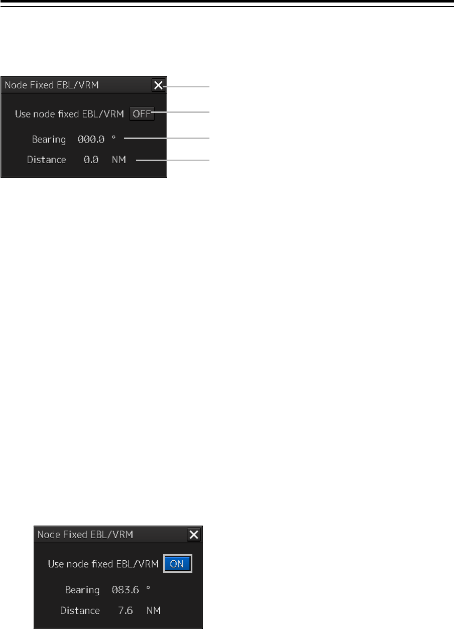
Section 4 Range and Bearing Measurement Methods 4-48
4.8.2 Description of "Node Fixed EBL/VRM" dialog
box
[1] [x] button
When the [x] button is clicked on, the "Node Fixed EBL/VRM" dialog box is closed.
[2] [Use Node Fixed EBL/VRM] button
This button sets the display of fixed position EBL/VRM to ON/OFF.
[ON]: The cursor mode is changed to the EBL/VRM marker intersection move mode.
[OFF]: Cancels the fixed position EBL/VRM display.
[3] Bearing up to the fixed position
Displays the bearing from the own ship to the fixed position.
The bearing is always reflected.
[4] Distance up to the fixed position
Displays the distance from the own ship to the fixed position.
The distance is always reflected.
4.8.3 Creating a new Node Fixed EBL/VRM
1 Set the function to ON by clicking on the [Use Node Fixed EBL/VRM] button.
The cursor mode is set to the EBL/VRM marker intersection move mode.
[1]
[2]
[4]
[3]
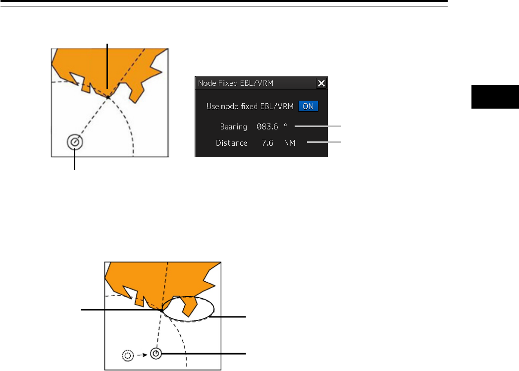
4-49 Section 4 Range and Bearing Measurement Methods
1
2
3
4
5
6
7
8
9
10
11
12
13
14
15
16
17
18
19
20
21
22
23
24
25
APP A
APP B
1
2 Determine the fixed position by clicking the position to be fixed.
The bearing and distance of the own ship against the fixed position are displayed on the
selected fixed position and these values change as the own ship advances.
[Relationship between the own ship and the fixed position when the own ship advances]
Even if the "Node Fixed EBL/VRM" dialog box is closed after the fixed position is determined,
the display of Node Fixed EBL/VRM remains.
After the fixed position is determined, the cursor mode changes to the AUTO mode.
When the mouse button is clicked on any position in Node Fixed EBL/VRM in AUTO mode, the
mode changes to the Node Fixed EBL/VRM intersection shift mode.
4.8.4 Cancelling the Node Fixed EBL/VRM function
1 Click the right mouse button in Node Fixed EBL/VRM intersection shift mode.
The mode is cancelled and the [Use Node Fixed EBL/VRM] button is set to OFF.
Fixed position
Own ship’s position
Bearing
Distance
Fixed position
The bearing and distance are displayed
h
Own ship
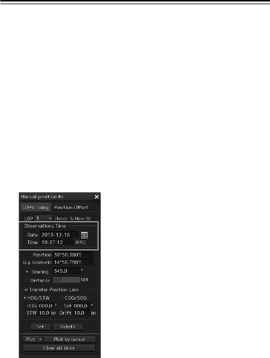
Section 4 Range and Bearing Measurement Methods 4-50
4.9 Measuring the Own Ship’s Position
Manually (LOPs Fixing Function of
Manual position fix)
This function is used for measuring the own ship’s position based on the following navigation and
plotting on the chart by using LOP (Line Of Position).
The own ship’s position can also be jumped to the plotted position.
4.9.1 Displaying the "Manual position fix" dialog
box
1 Click on the [Menu] button on the left toolbar.
The menu is displayed.
2 Click on the [Tools] - [Manual Position Fix] button on the menu.
The "Manual Position Fix" dialog box appears.
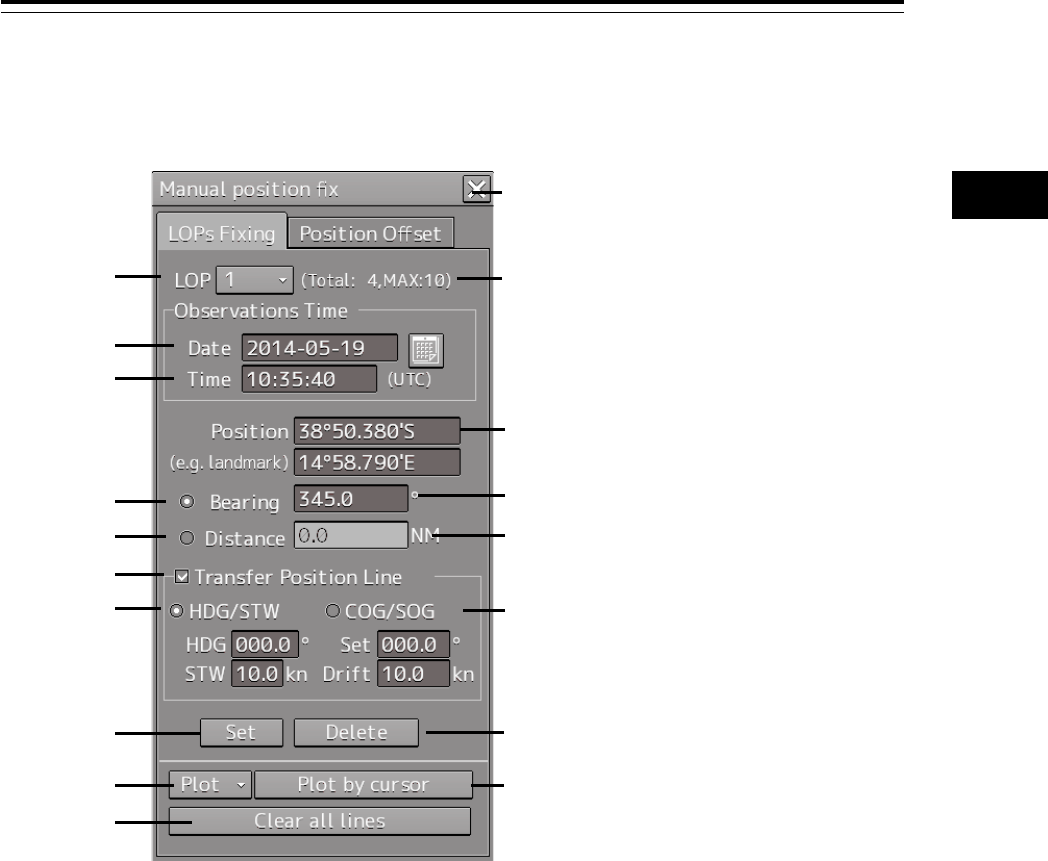
4-51 Section 4 Range and Bearing Measurement Methods
1
2
3
4
5
6
7
8
9
10
11
12
13
14
15
16
17
18
19
20
21
22
23
24
25
APP A
APP B
1
4.9.2 Description of the "LOPs Fixing" tab of the
"Manual position fix" dialog box
[1] [X] button
Use this button to close the "Manual position fix" dialog box.
[2] [LOP] (LOP selection combo box)
When a LOP number (1 to 10) is selected from the list, the LOP is switched to the generated LOP
corresponding to the number.
[3] Display of the number of LOPs
The maximum number of LOPs that can be created and the number of LOPs that have been created
are displayed.
[4] [Date] (Observation date)
When the text box is clicked on, a calendar picker is displayed, enabling input of an observation date.
[5] [Time] (Observation time)
When the text box is clicked on, a calendar picker is displayed, enabling input of an observation time.
[1]
[3]
[6]
[8]
[10]
[13]
[15]
[17]
[16]
[18]
[12]
[14]
[11]
[9]
[7]
[5]
[4]
[2]

Section 4 Range and Bearing Measurement Methods 4-52
[6] [Position] (LOP reference point)
Set a reference point by entering a LOP reference point through the software keyboard or clicking on
any position on the chart.
[7] [Bearing] (Selection of LOP bearing mode)
When this item is selected, LOP is switched to the bearing mode.
[8] LOP bearing input box
Enter a bearing of LOP. The input is enabled when LOP is in bearing mode.
[9] [Distance] (Selection of LOP distance mode)
When this item is selected, LOP is switched to the distance mode.
[10] LOP distance input box
Enter a distance of LOP. The input is enabled when LOP is in distance mode.
[11] [Transfer Position Line] (TPL ON/OFF)
When this item is checked, TPL (Transfer Position Line) is drawn by determining the transfer amount
from the observation time differences of all other LOPs, the bearing and speed of the ship and the
current direction and the current speed. However, transfer does not occur to the past LOP.
[12] [HDG/STW] (Selection of speed through water)
When this item is selected, TPL is determined from the speed through water, the current direction, and
the current speed.
This item can be selected when [Transfer Position Line] is checked.
[13] [COG/SOG] (Selection of speed over the ground)
When this item is selected, TPL is determined from the speed over the ground.
This item can be selected when [Transfer Position Line] is checked.
[14] [Set] button
When this item is clicked on, the LOP that was created is determined and control is passed to the next
LOP creation mode.
[15] [Delete] button
When this button is clicked on, the LOP that was selected on the LOP selection combo box is deleted.
[16] [Plot] button
When this button is clicked on, the following menu is displayed.
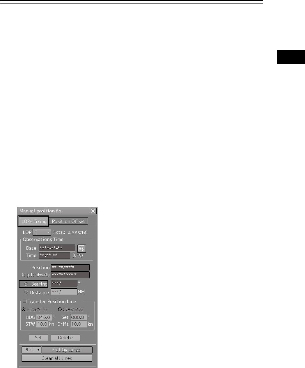
4-53 Section 4 Range and Bearing Measurement Methods
1
2
3
4
5
6
7
8
9
10
11
12
13
14
15
16
17
18
19
20
21
22
23
24
25
APP A
APP B
1
[Set plotted position]: Creates a reference point on the plotted position on the chart.
[Offset to plotted POSN(Main)]: Creates a reference point on the position determined by offsetting
from plotted position by POSN.
[Offset to plotted POSN(Sub)]: Creates a reference point on the position determined by offsetting
from plotted position by POSN.
[17] [Plot by cursor] button
When the mouse button is clicked on this button, the cursor shape changes to the offset cursor,
enabling creation of a Plotted Position on the coordinates on which the button was clicked with the
offset cursor.
[18] [Clear all lines] button
When this button is clicked, all the LOPs that were created are deleted.
4.9.3 Creating LOP
4.9.3.1 Creating bearing LOP
1 After confirming that the "LOPs Fixing" tab is selected, select [Bearing].
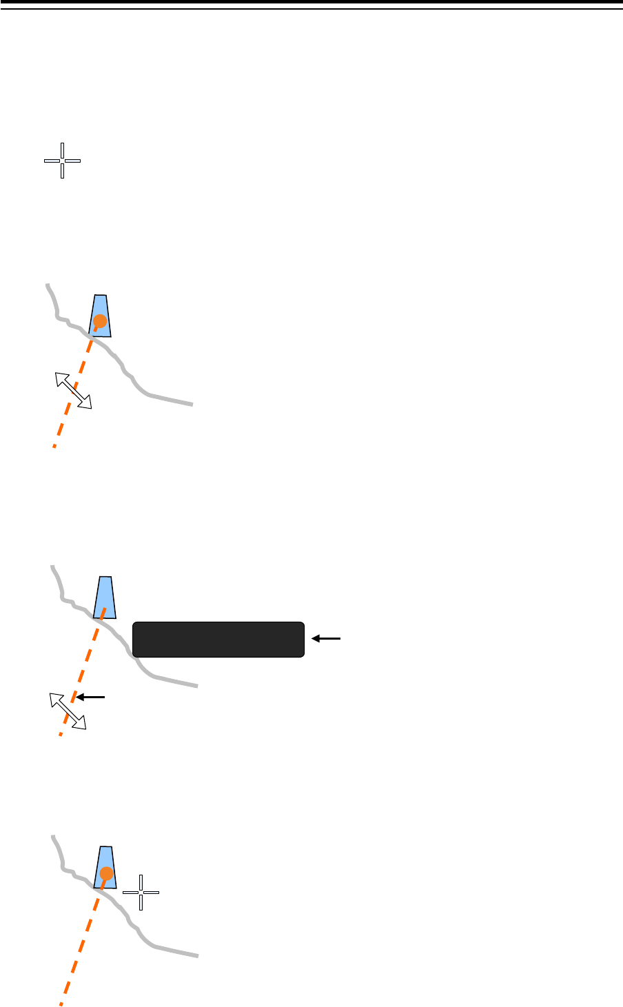
Section 4 Range and Bearing Measurement Methods 4-54
2 Place the cursor on the reference point.
The cursor (mark cursor) of the LOP reference point setting mode for the first LOP is displayed.
In this case, the LOP starts from the edge of the screen and the LOP reference point is the
cursor position.
3 Set the cursor to the target that was used for bearing measurement and click the
mouse button. The cursor changes to the bearing setting cursor.
4 Move the cursor to set the bearing to the measured bearing and determine the bearing
of the LOP by clicking the mouse button.
The measurement can also be determined by entering a numeric value in the Bearing
text box.
When the bearing of LOP is determined, the mark cursor is displayed and the cursor mode is
changed to the reference point setting mode.
Mark
Bear i ng 35.5 °
LOP:
Moves by linking with the cursor.
Can also be rotated by using the EBL
dial.
Displays the bearing of LOP
around the reference point in real
time
Mark
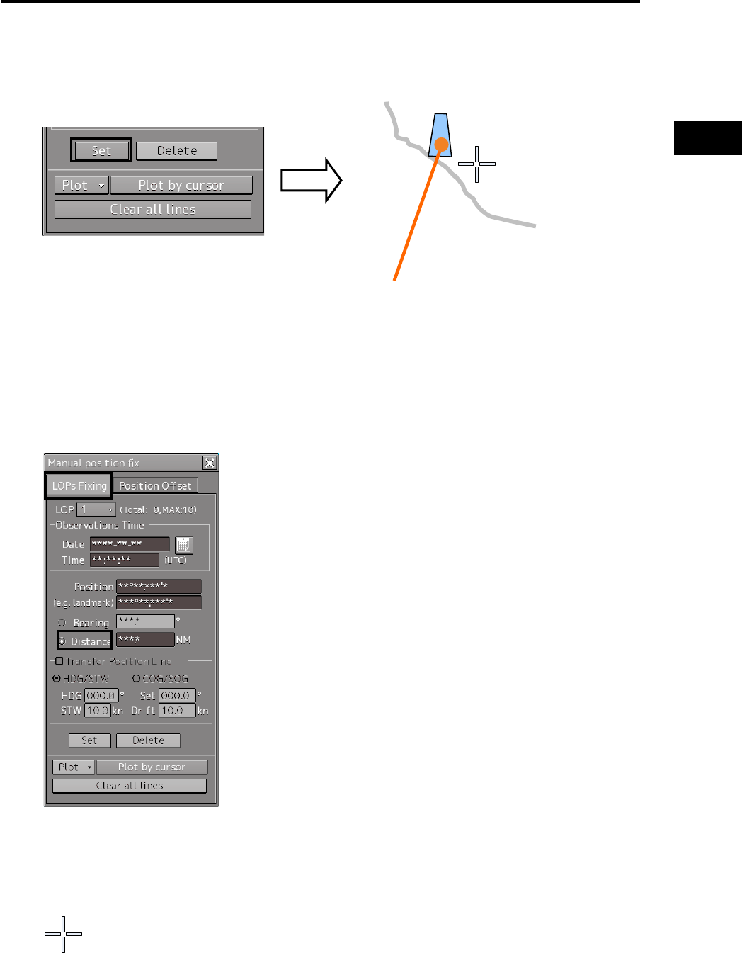
4-55 Section 4 Range and Bearing Measurement Methods
1
2
3
4
5
6
7
8
9
10
11
12
13
14
15
16
17
18
19
20
21
22
23
24
25
APP A
APP B
1
5 Determine the 1st LOP by clicking on the [Set] button.
The 2nd LOP is selected in the LOP selection combo box.
When LOP is determined, the broken line is changed to a solid line.
4.9.3.2 Creating distance LOP
1 Check that the "LOPs Fixing" tab is displayed and select [Distance].
2 Place the cursor on the reference point.
The cursor (mark cursor) is displayed.
Mark
45.5
1314
Mark
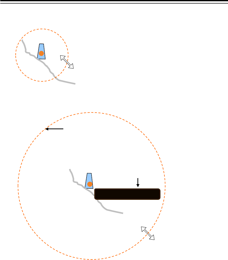
Section 4 Range and Bearing Measurement Methods 4-56
3 When the cursor is moved to the target that is used for distance measurement and the
mouse button is clicked on, the cursor changes to the arrow cursor.
4 Move the cursor to the measured distance and determine the LOP distance by clicking
the button.
4.9.4 Measuring the own ship’s position in cross
bearing fix
This section describes the own ship position fixing and offset procedures by cross bearing (cross
position fixing method).
In cross bearing, creation of a Plotted Position and offset operation can be performed concurrently.
When the own ship’s position is unclear due to the occurrence of abnormality in the position sensor
such as a navigation unit, the position of own ship can be determined by drawing a line of the bearing
of the fixed target visually on the chart by using cross bearing.
LOP:
Moves by linking with the cursor.
Can also be rotated by using the
[VRM] dial.
Displays the distance of LOP
around the reference point in
real time
Disatance 10.0NM
Distance 10.0NM
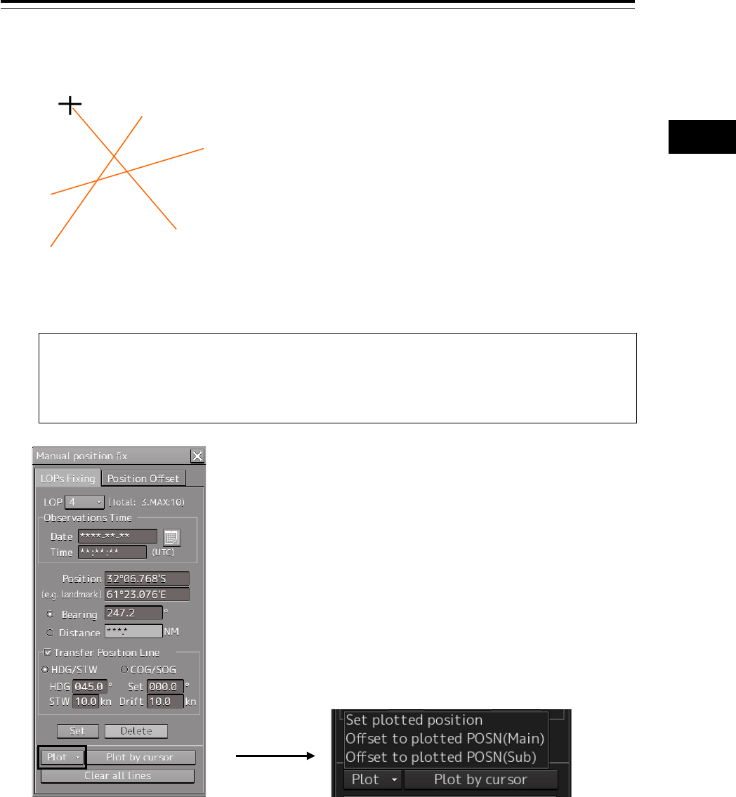
4-57 Section 4 Range and Bearing Measurement Methods
1
2
3
4
5
6
7
8
9
10
11
12
13
14
15
16
17
18
19
20
21
22
23
24
25
APP A
APP B
1
4.9.4.1 Automatic position fixing
1 Create two or more LOPs to create intersecting points.
2 Click the [Plot] combo box.
Memo
The following menu is displayed only when two or more LOPs are determined.
When there are three or more LOPs or TPLs, refer to "4.9.4.4 When there are three or more
LOPs or TPLs".

Section 4 Range and Bearing Measurement Methods 4-58
3 Select [Set plotted position].
A Plotted Position is displayed on the appropriate intersecting point.
When there are two LOPs, the intersecting point is used as the position fixing candidate and
when there are three LOPs and a differential triangle is generated, the inner center is used as
the position fixing candidate.
4 Set a Plotted Position in the "Plotted Position" dialog that is displayed at creation of a
Plotted Position.
For the details of the "Plotted Position" dialog box, refer to "4.9.4.5 Setting a plotted position".
4.9.4.2 Automatic offset
1 Create two or more LOPs to create intersecting points.
DR GNSS
Triangle of error
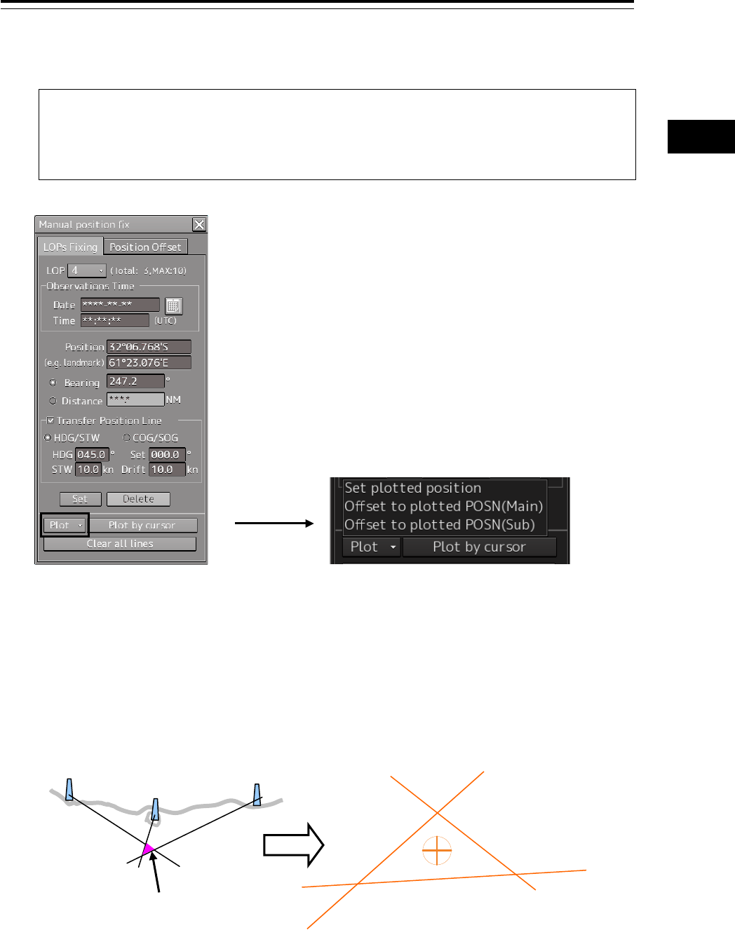
4-59 Section 4 Range and Bearing Measurement Methods
1
2
3
4
5
6
7
8
9
10
11
12
13
14
15
16
17
18
19
20
21
22
23
24
25
APP A
APP B
1
2 Click the [Plot] combo box.
Memo
The following menu is displayed only when two or more LOPs are determined.
When there are three or more LOPs or TPLs, refer to "4.9.4.4 When there are three or more
LOPs or TPLs".
3 Select [Set plotted position].
A Plotted Position is displayed on the appropriate intersecting point.
When there are two LOPs, the intersecting point is used as the position fixing candidate and
when there are three LOPs and a triangle of error is generated, the inner center is used as the
position fixing candidate.
DR GNSS
Triangle of error
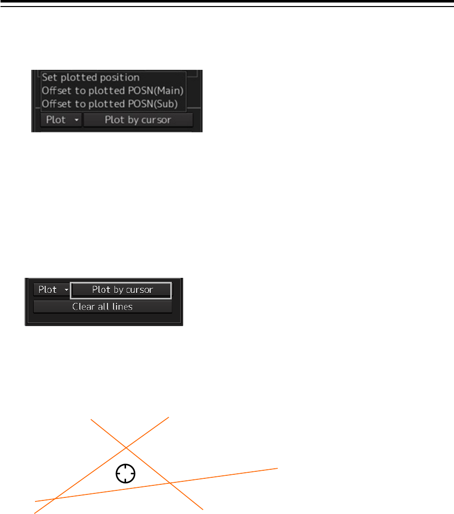
Section 4 Range and Bearing Measurement Methods 4-60
4 Select [Offset to plotted POSN(Main)] or [Offset to plotted POSN(SUB)] from the [Plot]
combo box.
• When [Offset to plotted POSN(Main)] is selected, a reference point is created by offsetting by
POSN1 from the plotted position.
• When [Offset to plotted POSN(Sub)] is selected, a reference point is created by offsetting by
POSN2 from the plotted position.
4.9.4.3 Manual position fixing
1 Click on the [Plot by cursor] button.
The mode is changed to the manual plot mode and the offset cursor is displayed.
2 Click inside of the triangle of error with the offset cursor.
A Plotted Position is displayed on the coordinate that was clicked on and the "Plotted Position"
dialog box appears.
3 Set a Plotted Position in the "Plotted Position" dialog that is displayed at creation of a
Plotted Position.
For the details of the "Plotted Position" dialog box, refer to the "4.9.4.5 Setting a plotted
position".
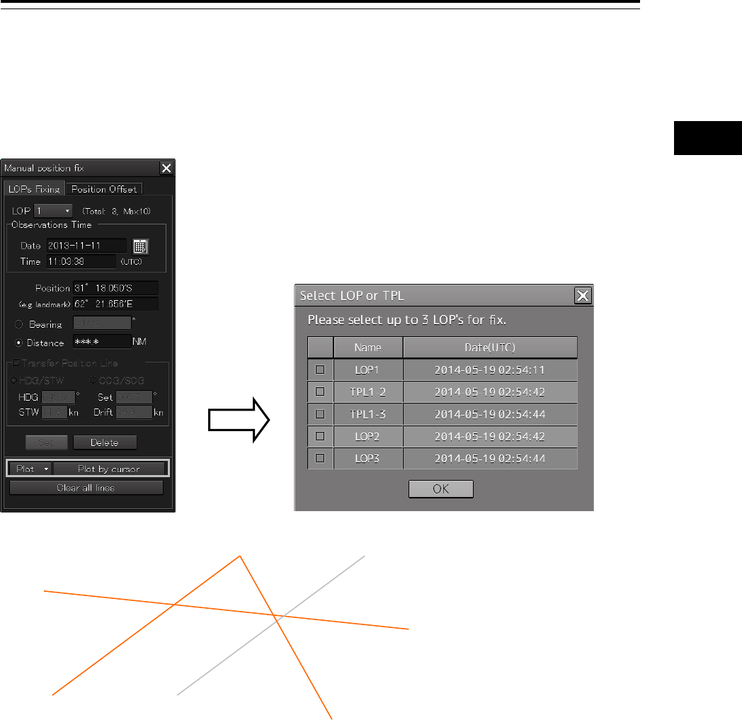
4-61 Section 4 Range and Bearing Measurement Methods
1
2
3
4
5
6
7
8
9
10
11
12
13
14
15
16
17
18
19
20
21
22
23
24
25
APP A
APP B
1
4.9.4.4 When there are three or more LOPs or TPLs
When there are three or more LOPs or TPLs in total and the [Set plotted position] button is clicked on,
the "Select LOP or TPL" dialog box appears.
Select LOP or TPL on the chart from this dialog box.
LOP3
LOP1
TPL1
LOP2
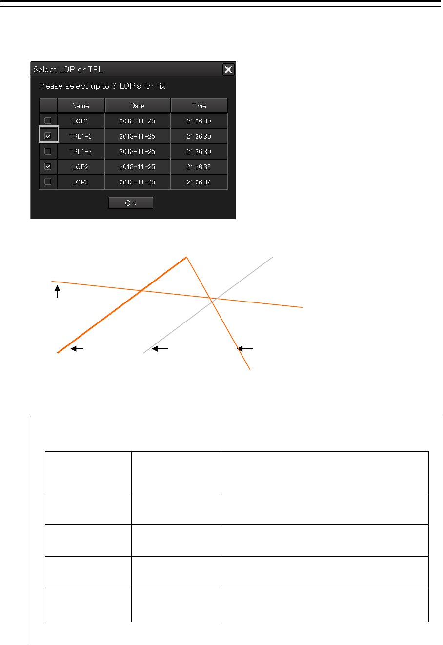
Section 4 Range and Bearing Measurement Methods 4-62
1 Select a LOP or TPL checkbox.
The selected LOP or TPL is highlighted.
2 Close the dialog box by clicking on the [OK] button.
Important
The [OK] button on the dialog box is enabled under the following conditions only.
Position fixing
method
Pattern where the
[OK] button
is enabled
Remarks
Cross Bearing • BRG×2
BRG×3
LOP bearing only is available for Cross
Bearing.
Running fix • BRG×1 TPL×1
BRG×1 TPL×2
LOP and TPL bearing only are available for
Running fix.
Bearing Distance • BRG×1 DST×1 For Bearing Distance, the position is fixed by
one LOP bearing and one LOP distance.
Radar fix • DST×2
• DST×3
LOP distance only is available for Radar fix.
* BRG means "bearing LOP" and RNG means "distance LOP".
TPL display example
For instance, "TPL1-2" is expressed with
the "LOP number" that is checked in
[Transfer Position Line] and "LOP
number of creation destination (transfer
destination").
LOP3
LOP1
TPL1
LOP2
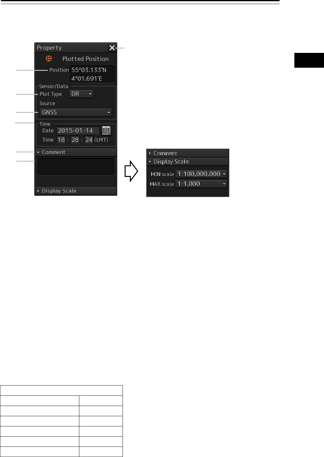
4-63 Section 4 Range and Bearing Measurement Methods
1
2
3
4
5
6
7
8
9
10
11
12
13
14
15
16
17
18
19
20
21
22
23
24
25
APP A
APP B
1
4.9.4.5 Setting a plotted position
[1] [X] button
Close the "Reference Point" dialog box.
[2] [Position]
Enter the coordinate of the Plotted Position.
[3] [Plot type] combo box
Switched between blank, DR(Dead Reckoning) and EP(Estimated Position).
Position by dead-reckoning (DR: Dead-Reckoning)
Position that is assumed based on the current course and speed
Estimated position (EP)
Position that is assumed by including the influence of wind and current in addition to the current course
and speed
[4] [Source] (Data source) combo box
Select a data source from the list containing following 11 types.
Data source
Blank
GPS
GNSS
DGPS
LORAN
DECCA
RADAR Range
Astronomical
Visual Bearing
MFDF
Visual BRG/RADAR RNG
TRANSIT
When the Disclosure button is
clicked on, the setting dialog is
displayed.
[1]
[6]
[5]
[4]
[3]
[2]
[7]
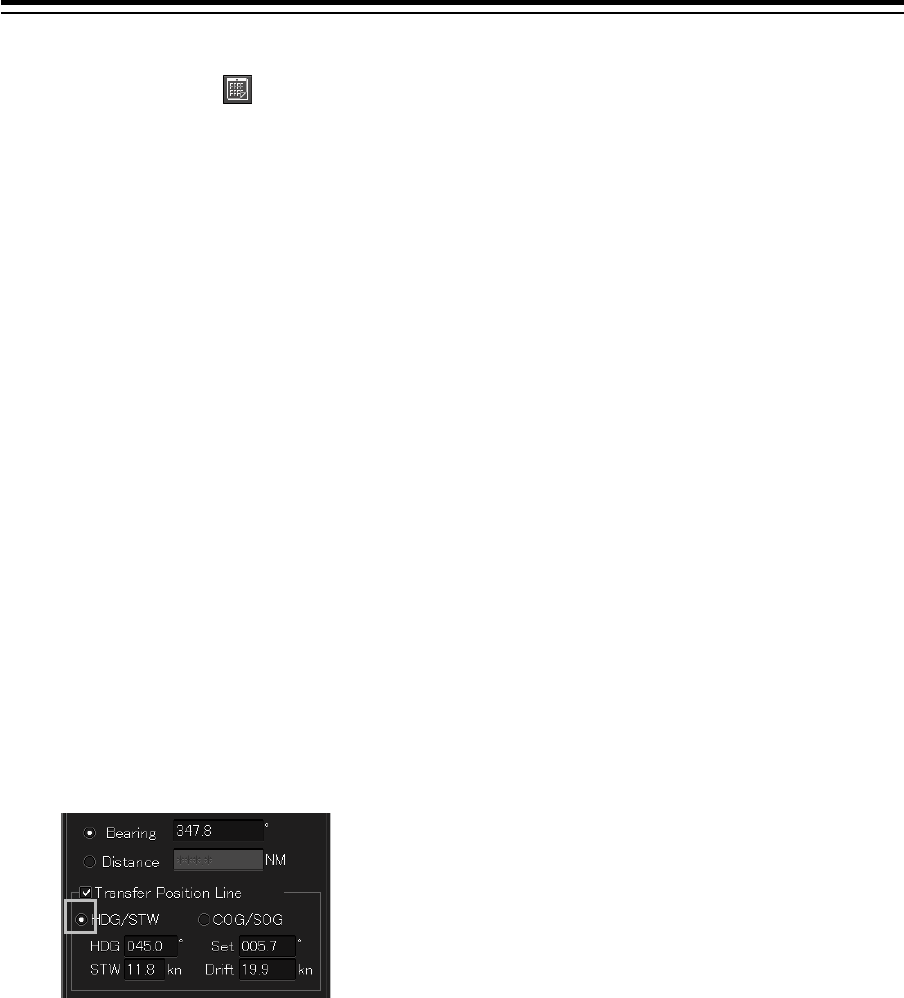
Section 4 Range and Bearing Measurement Methods 4-64
[5] [Time]
When the calendar icon is clicked on, a calendar picker is displayed, enabling input of date and
time.
[6] [Comment]
When the disclosure button of the Comment is clicked on, an input column is displayed. Enter a
comment (up to 64 characters).
[7] Display Scale
When the disclosure button of Display Scale is clicked on, the scale range (minimum scale to
maximum scale) for Plotted Position on the chart is displayed.
Select the minimum scale (MIN scale) and the maximum scale (MAX scale) as required.
4.9.5 Measuring the own ship’s position with
Running Fix
By using two LOPs and TPLs (Transfer Position Line) that were created at different times, an
intersecting point or a triangle of error is created and the position is fixed.
The same procedure as for cross bearing is applied for automatic position fixing and manual position
fixing.
1 Select the [Transfer Position Line] (ON/OFF of TPL) checkbox.
2 Select a TPL calculation method.
When determining TPL from the ship’s heading through water, ship’s speed, current direction,
and current speed, select [HDG/STW].
To change the ship’s heading, ship’s speed through water, current direction, and current speed
subsequently, change the value in each of the [HDG], [STW], [Set], and [Drift] boxes. To
determine TPL from the ship’s speed, select [COG/SOG].
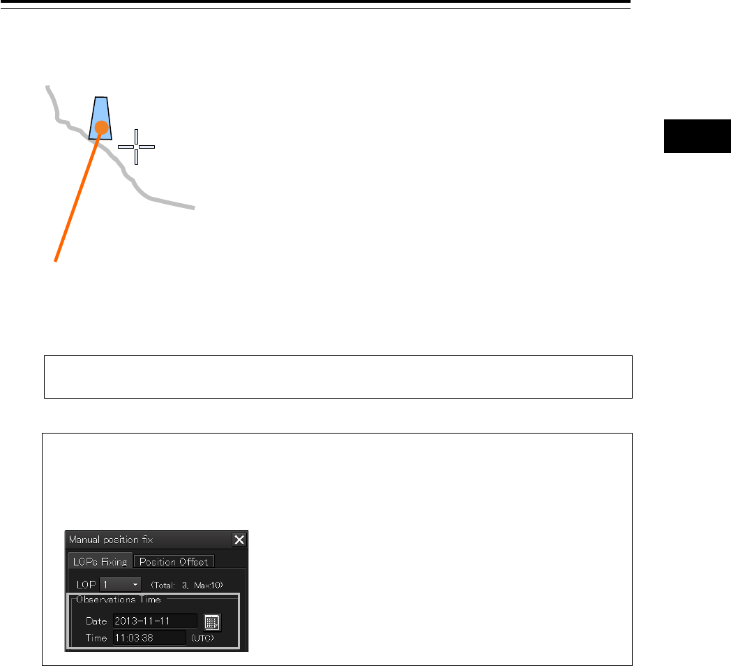
4-65 Section 4 Range and Bearing Measurement Methods
1
2
3
4
5
6
7
8
9
10
11
12
13
14
15
16
17
18
19
20
21
22
23
24
25
APP A
APP B
1
3 Create the 1st LOP and click on the [Set] button.
4 Wait until the ship moves for a while.
Note
While the ship is moving, do not change the bearing and speed of own ship.
Memo
When the traveling distance is available from the time difference from the 1st LOP to the
observation time and the direction and speed of the ship, the 2nd LOP can also be created
by entering the Observation Time of the LOP without waiting for the movement of the ship.
5 Select the [Transfer Position Line] check box.
Mark
45.5
1314
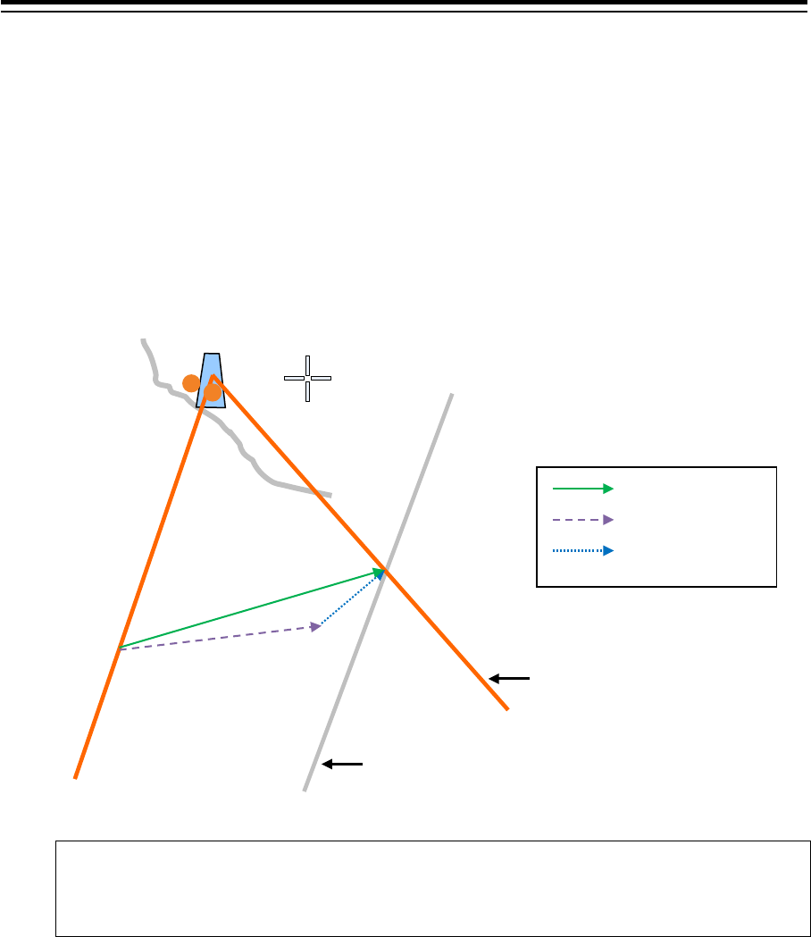
Section 4 Range and Bearing Measurement Methods 4-66
6 Create the second LOP with the same procedure as for cross bearing.
TPL is automatically drawn by determining the traveling distance from the time difference from
the 1st LOP to the observation time and the bearing and speed of the ship. The intersection
between the 2nd LOP and TPL becomes the own ship’s position based on the both-side
positioning method.
• When [HDG/STW] is set to ON, TPL of the same angle as that of the 1st LOP and same
time as that of 2nd LOP is created based on the position determined by adding the
HDG/STW vector and the Set/Drift vector.
• When [COG/SOG] is ON, TPL is created by using COG/SOG.
Note
Since transfer to the past LOP is not possible, TPL cannot be created when the time of LOP
is prior to the time of LOP1.
1324
235.5
TPL
Mark
45.5
1314
1314
COG/SOG
HDG/STW
Set/Drift
The second LOP is determined
10 minutes after.
When the second LOP is determined, TPL
is displayed by using the first LOP.
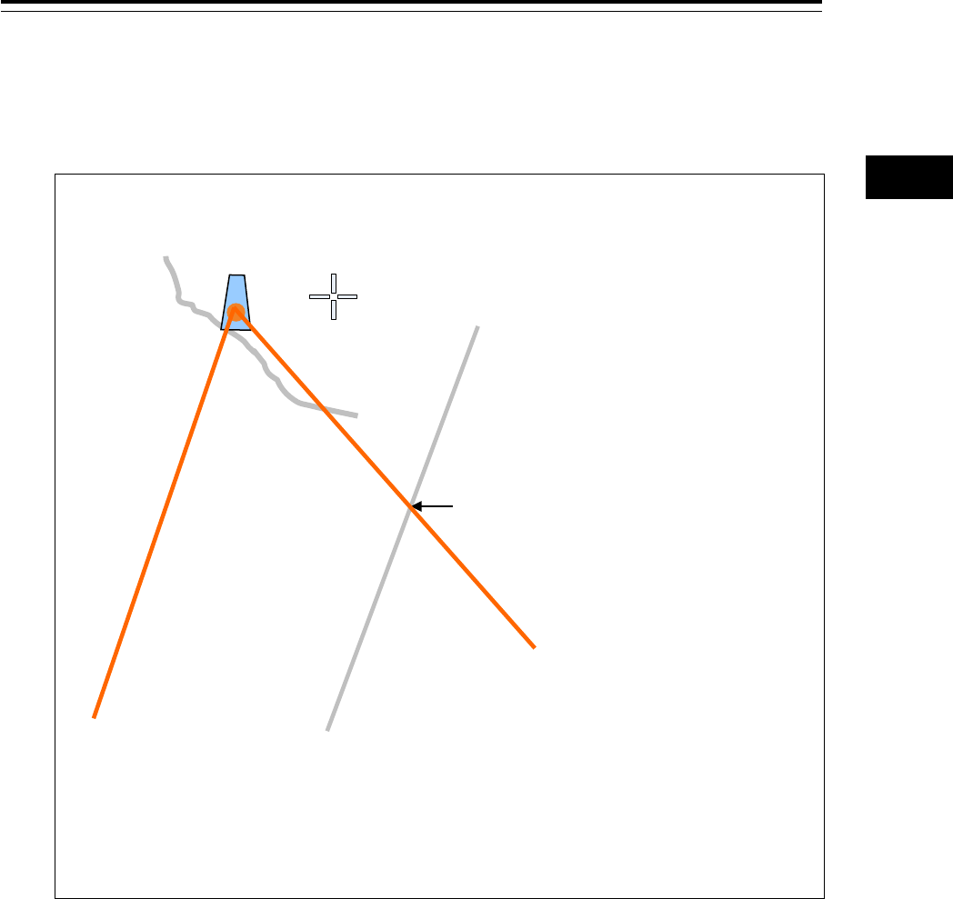
4-67 Section 4 Range and Bearing Measurement Methods
1
2
3
4
5
6
7
8
9
10
11
12
13
14
15
16
17
18
19
20
21
22
23
24
25
APP A
APP B
1
7 When using the intersection between LOP and TPL as the Plotted Position, perform the
operation that is described in Memo.
When using a triangle of error as the Plotted Position, advance to Step 8.
Memo
The intersection between LOP and TPL can also be used as the Plotted Position.
1 Select [Set plotted position] from the [Plot] button while an intersection is created from
the 2nd LOP and 1st TPL.
The "Select LOP or TPL" dialog is displayed.
2 Select the 2nd LOP and 1st TPL and click on the [OK] button.
A Plotted Position is set at the intersection of the 2
nd
LOP and 1
st
TPL.
8 Check [Transfer Position Line].
9 Click on the [Set] button by creating the 2nd L O P.
TPL is automatically drawn by determining the traveling distance from the time difference from
the 2nd LOP to the observation time and the bearing and speed of the ship.
Two TPLs are created, creating a triangle of error.
10 Select [Set plotted position] from the [Plot] button.
The "Select LOP or TPL" dialog is displayed.
11 Select LOP and TPL that form a triangle of error and click on the [OK] button.
A Plotted Position is set inside of the triangle of error.
1324
235.5
TPL
45.5
1314
1314
Intersection of the 2
nd
LOP
and 1st TPL
Mark
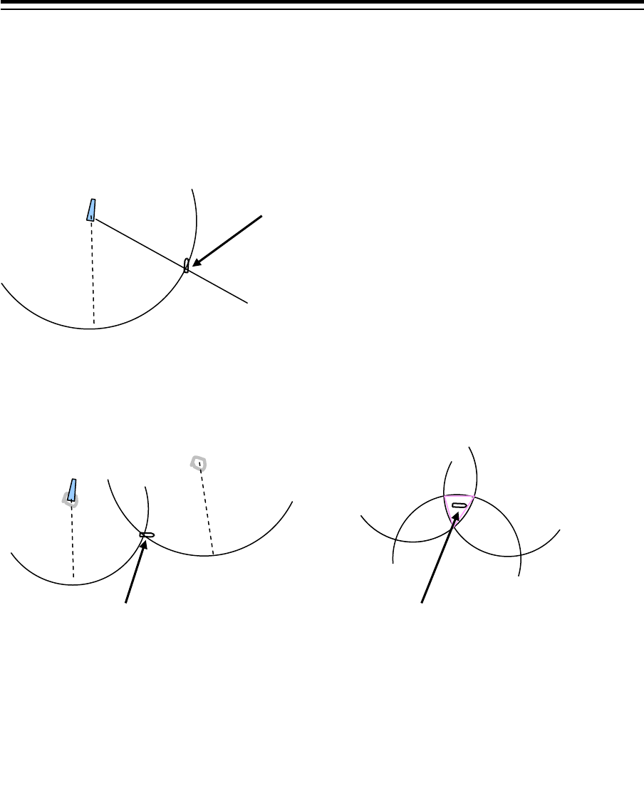
Section 4 Range and Bearing Measurement Methods 4-68
4.9.6 Measuring the own ship’s position with other
methods
Bearing and Distance
Perform position fixing from one target with one Bearing and one Distance.
Distance
Perform position fixing from the distance intersecting point from 2 to 3 targets.
The intersection becomes the own ship’s position.
However, when multiple intersections are created, the one
closest to the own ship’s position among those that are
displayed in the own ship information area is used as the
own ship’s position. In this case, the own ship’s position is
outside of the sensor detection range, the position closest
from the bearing starting point is used as the own ship’s
position.
The intersection becomes the own ship’s
position.
However, when multiple intersections are
created, the one closest to the own ship’s
position among those that are displayed in the
own ship information area is used as the own
ship’s position. In this case, the own ship’s
position is outside of the sensor detection
range, the position closest from the bearing
starting point is used as the own ship’s position.
Inner center (position closer to the own ship’s
position) of the triangle of error created by 3
intersecting points when there are 3 distance
LOPs.
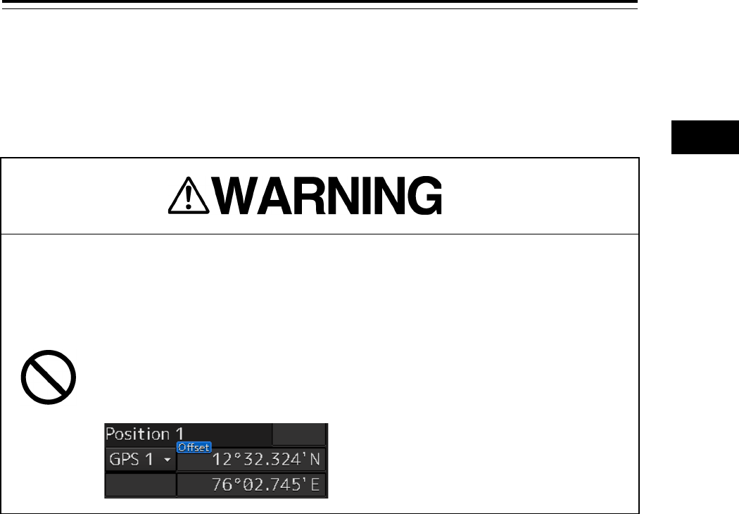
4-69 Section 4 Range and Bearing Measurement Methods
1
2
3
4
5
6
7
8
9
10
11
12
13
14
15
16
17
18
19
20
21
22
23
24
25
APP A
APP B
1
4.10 Offsetting the Own Ship’s Position
Manually (Position Offset Function of
Manual position fix)
Do not use the offset function during the voyage.
If the function is used while an offset value is input in the own ship’s position
(different from the actual position), an accident may occur.
When an offset value is input, the [Offset] badge is displayed in the position
display section of Own Ship Information. Check if the own ship is off course
with this position display section. The "Position Shift" message is also
displayed in the message area.
4.10.1 Displaying the "Manual position fix" dialog
box
1 Click on the [Menu] button on the left toolbar.
The menu is displayed.
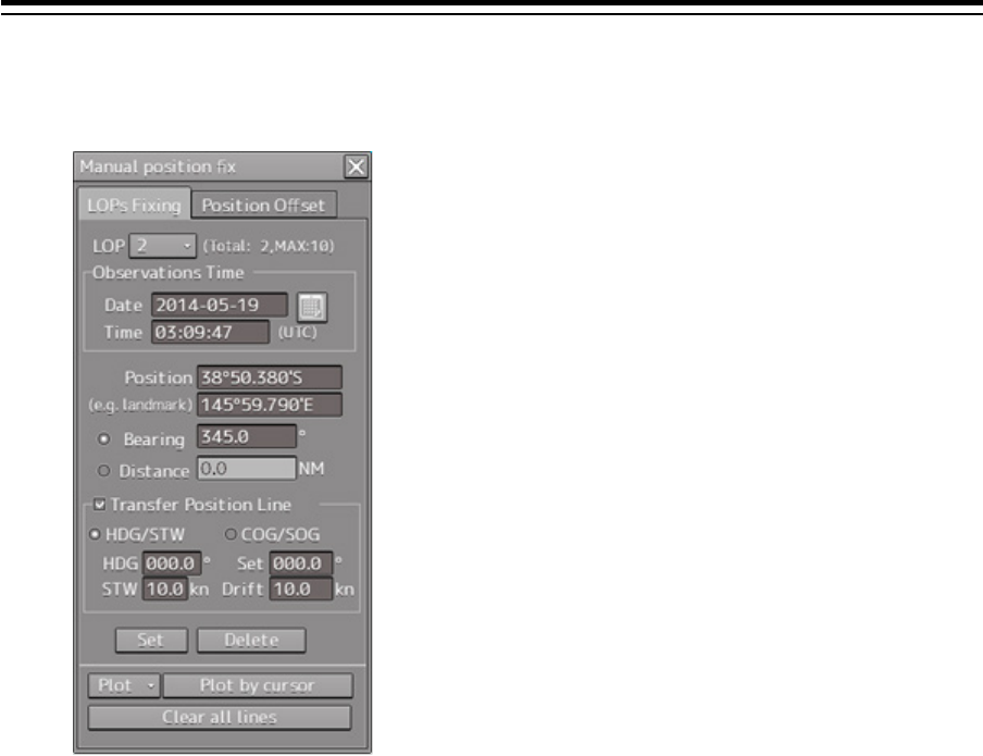
Section 4 Range and Bearing Measurement Methods 4-70
2 Click on the [Tools] - [Manual Position Fix] button on the menu.
The "Manual position fix" dialog box appears.
3 Click on the [Position Offset] tab.
The "Position Offset" dialog box appears.
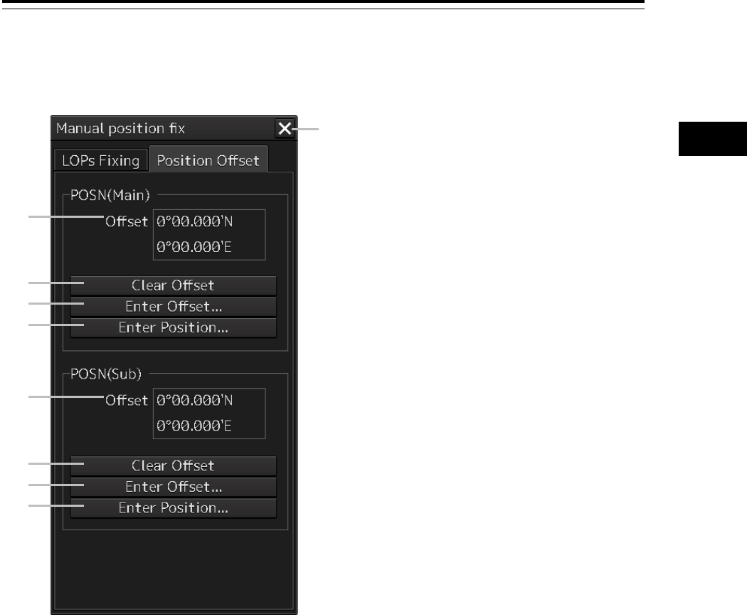
4-71 Section 4 Range and Bearing Measurement Methods
1
2
3
4
5
6
7
8
9
10
11
12
13
14
15
16
17
18
19
20
21
22
23
24
25
APP A
APP B
1
4.10.2 Description of the [Position Offset] tab of the
"Manual position fix" dialog box
[1] [X] button
This button closes the "Manual position fix" dialog box.
[2] [Offset] ([POSN(Main)] coordinate after offset)
The offset amount that was offset by Enter Offset and Enter Position is displayed.
[3] [Clear Offset] (Clearing the offset value of [POSN(Main)]) button
The offset value of [POSN(Main)] is cleared.
[4] [Enter Offset] (Input of the offset value of [POSN(Main)]) button
This button displays the "Enter Offset" dialog box.
For the details, refer to "4.10.3 Setting the offset amount that is input in the "Enter Offset" dialog as the
offset position".
[5] [Enter Position] (Coordinate input of [POSN(Main)]) button
This button displays the "Enter Position" dialog box.
For the details, refer to "4.10.4 Setting the position on the chart on which the mouse button was clicked
as the offset position".
[1]
[8]
[9]
[7]
[6]
[5]
[4]
[3]
[2]
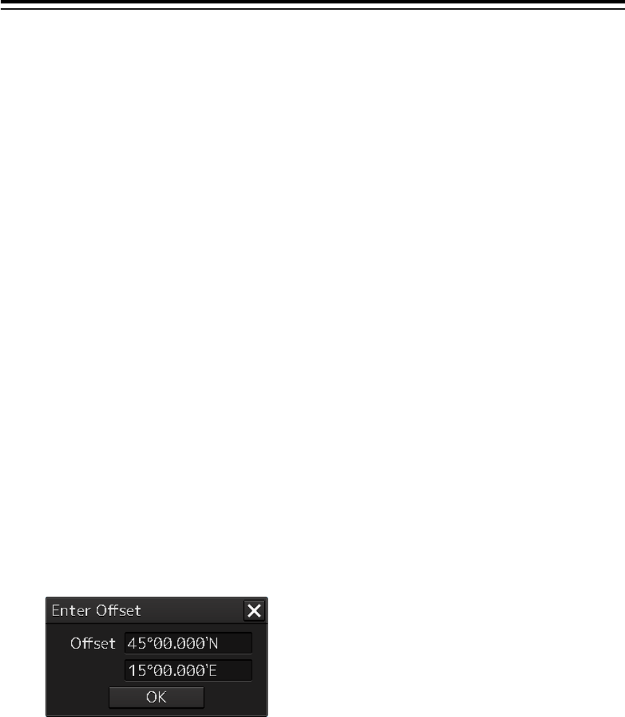
Section 4 Range and Bearing Measurement Methods 4-72
[6] [Offset] (Post-offset [POSN(Sub)]coordinate]
The offset amount is displayed.
[7] [Clear Offset] (Clearing the [POSN(Sub)] offset value) button
The offset value of [POSN(Sub)] is cleared.
[8] [Enter Offset] (Input of offset value of [POSN(Sub)]) button
This button displays the "Enter Offset" dialog box.
For the details, refer to "4.10.3 Setting the offset amount that is input in the "Enter Offset" dialog as the
offset position".
[9] [Enter Position] (Coordinate input of [POSN(Sub)]) button
This button displays the "Enter Position" dialog box.
For the details, refer to "4.10.4 Setting the position on the chart on which the mouse button was clicked
as the offset position".
4.10.3 Setting the offset amount that is input in the
"Enter Offset" dialog as the offset position
1 Click on the [Enter Offset] (Setting the offset amount) button of [POSN(Main)] or
[POSN(Sub)].
The "Enter Offset" dialog is displayed.
2 Enter an offset value through the software keyboard.
3 Click on the [OK] button.
The offset amount that was input is set as the offset position.
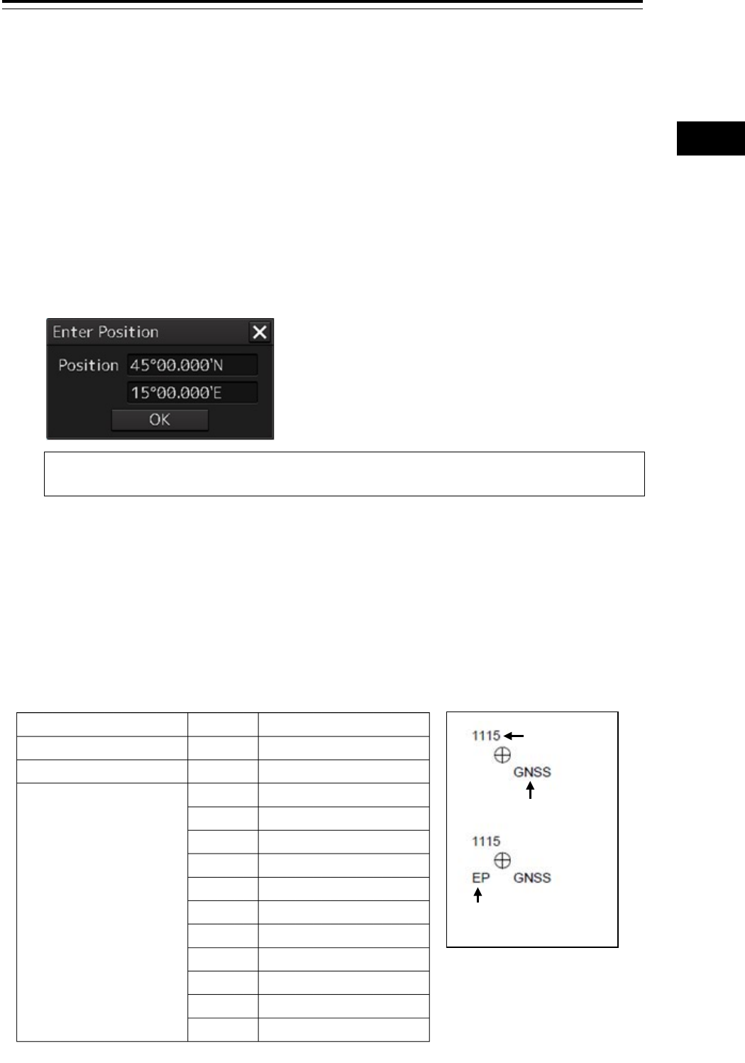
4-73 Section 4 Range and Bearing Measurement Methods
1
2
3
4
5
6
7
8
9
10
11
12
13
14
15
16
17
18
19
20
21
22
23
24
25
APP A
APP B
1
4.10.4 Setting the position on the chart on which the
mouse button was clicked as the offset
position
1 Click on the [Enter Position] (input of coordinates) button of [POSN(Main)] or
[POSN(Sub)].
The "Enter Position" dialog is displayed.
While the dialog is displayed, the cursor changes to the offset cursor and the mode changes to
the position selection mode.
2 The position is displayed in [Position] in the dialog as the coordinate of the position on
the chart on which the mouse button was clicked.
Memo
Post-offset coordinates can also be input from the software keyboard.
3 Click on the [OK] button.
The coordinate is set in the offset position.
Notation of Plotted Position on the chart
When offset is applied to automatic plot, manual plot, or own ship’s position, the time and source are
displayed near the symbol.
The source is displayed with the following label.
Source label
Time
EP
Label Details
Estimated position EP
Dead reckoned position DR
Plotted Position GNSS GNSS
L Loran
R Radar range
V Visual bearing
VR Visual BRG/Radar RNG
G GPS
dG DGPS
D Decca
A Astronomical
M MFDF
T TRANSIT
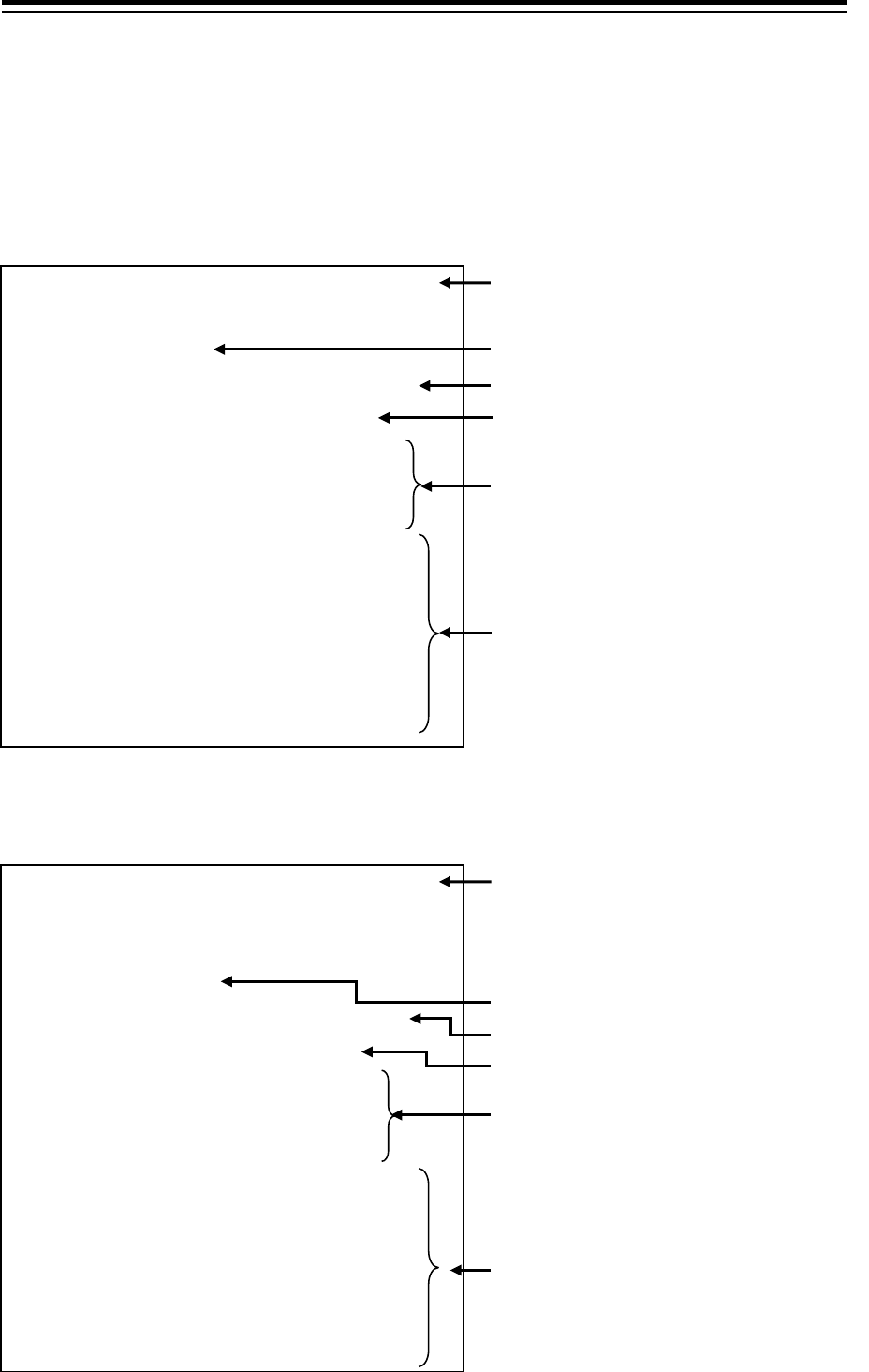
Section 4 Range and Bearing Measurement Methods 4-74
4.10.5 Recording LOPs Fixing operation in the
logbook
A comment can be registered in the log book by using the following procedure.
Display example when a Plotted Position is created by using Set plotted position or
Plot by cursor.
Display example when the own ship position is offset by
[Offset to plotted POSN(Main/Sub).
Fixed position was plotted at Jan 01,2012 12:00:48
by "Set plotted position".
Offset: 0.8 NM, 014.6°
Plotted position: 60°12.493' N, 027°48.254' E
The following lines of position were used.
LOP1: Jan 01,2012 11:57:22, BRG = 044.6°
LOP2: Jan 01,2012 11:58:27, BRG = 322.0°
LOP3: Jan 01,2012 11:58:52, BRG = 266.1°
Intersection of LOP1 and LOP2: 60°20.623' N,
028°06.209' E
Intersection of LOP1 and LOP3: 60°16.684' N,
027°40.879' E
Intersection of LOP2 and LOP3: 60°12.249' N,
027°38.318' E
Coordinates at creation of the Plotted Position
Fixed character string
*Not displayed under Plot by cursor
Intersection coordinate of LOP
* Not displayed under Plot by cursor
Offset value
LOP type (ascending order), creation date and
time, and bearing or distance
* 2 to 3 LOPs are used for position fixing.
* For bearing, BRG is displayed and for
distance, DST is displayed.
* Not displayed under Plot by cursor
Plotted Position creation date and time and
Plot type
Main position was offset at Jan 01,2012,12:00:48 by
"Offset to plotted
POSN(Main)".
Offset: 0.8 NM, 014.6°
Plotted position: 60°12.493' N, 027°48.254'E
The following lines of position were used.
LOP1: Jan 01,2012 11:57:22, BRG = 044.6°
LOP2: Jan 01,2012 11:58:27, BRG = 322.0°
LOP3: Jan 01,2012 11:58:52, BRG = 266.1°
Intersection of LOP1 and LOP2: 60°20.623' N,
028°06.209' E
Intersection of LOP1 and LOP3: 60°16.684' N,
027°40.879' E
Intersection of LOP2 and LOP3: 60°12.249' N,
027
°
38.318' E
Offset date and time and offset type
* When the position is offset by Offset to plotted
POSN(Main), "Main position" is displayed and
when the position is offset by Offset to plotted
POSN(Sub), "Sub position" is displayed.
Intersection coordinate of LOP
Offset value
LOP type (ascending order), creation date and
time, and bearing or distance
* 2 to 3 LOPs are used for position fixing.
* For bearing, BRG is displayed and for
distance, DST is displayed.
Offset coordinate
Fixed character string
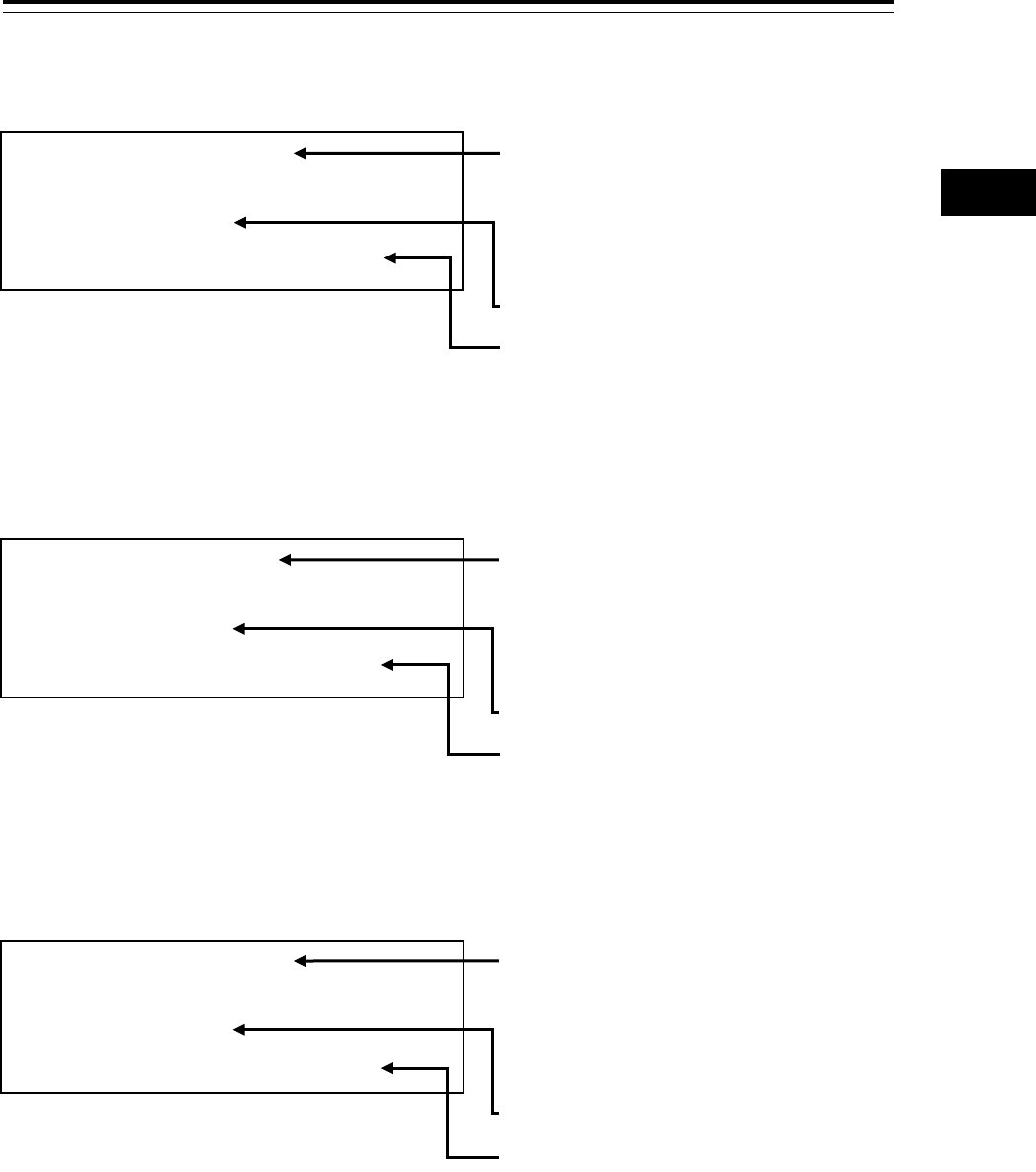
4-75 Section 4 Range and Bearing Measurement Methods
1
2
3
4
5
6
7
8
9
10
11
12
13
14
15
16
17
18
19
20
21
22
23
24
25
APP A
APP B
1
Display example when the own ship position is offset by Enter Offset of the
[Position Offset] tab
Display example when the own ship position is offset by Enter Position of the
[Position Offset] tab
Display example when the own ship position is offset by Clear Offset of the
[Position Offset] tab
Main position was offset at Jan
01,2012,12:00:48 by
"Enter Offset".
Offset: 0.8 NM, 014.6°
Offset date and time and offset type
* When the position is offset by using the
button in the POSN(Main), "Main position" is
displayed and when the position is offset by
using the button in the POSN(Sub) group,
"Sub position" is displayed.
Offset value
Offset coordinate
Main position was offset at Jan
01,2012,12:00:48 by "Enter Position".
Offset: 0.8 NM, 014.6°
Plotted position: 60°12.493' N, 027°48.254' E
Offset date and time and offset type
* When the position is offset by using the button
in the POSN(Main), "Main position" is
displayed and when the position is offset by
using the button in the POSN(Sub) group,
"Sub position" is displayed.
Offset value
Offset coordinate
Main position was offset at Jan
01,2012,12:00:48 by "Clear Offset".
Offset: 0.8 NM, 014.6°
Plotted position: 60°12.493' N, 027°48.254' E
Offset date and time and offset type
* When the position is offset by using the button
in the POSN(Main), "Main position" is
displayed and when the position is offset by
using the button in the POSN(Sub) group,
"Sub position" is displayed.
Offset value
Offset coordinate

Section 4 Range and Bearing Measurement Methods 4-76
4.10.6 Offsetting the own ship position
When the own ship position is offset by Offset to plotted POSN(Main/Sub) and Enter Offset, Enter
Position, and Clear Offset in Position Offset, the following character strings are registered in the
Logbook.
Item Statement Display contents
Offset to plotted
POSN(Main/Sub)
*For the "Offset to
plotted POSN(Main)"
section, "Offset to
plotted POSN(Main)" or
"Offset to plotted
POSN(Sub)" is
displayed.
Main position was offset at Jan
01,2012,12:00:48 by "Offset to plotted
POSN(Main)".
Offset: 0.8 NM, 014.6°
Plotted position: 60°12.493’ N,
027°48.254’ E
The following lines of position were used.
LOP1: Jan 01,2012 11:57:22, BRG =
044.6°
LOP2: Jan 01,2012 11:58:27, BRG =
322.0°
LOP3: Jan 01,2012 11:58:52, BRG =
266.1°
Intersection of LOP1 and LOP2:
60°20.623’ N, 028°06.209’ E
Intersection of LOP1 and LOP3:
60°16.684’ N, 027°40.879’ E
Intersection of LOP2 and LOP3:
60°12.249’ N, 027°38.318’ E
- First line: Offset date and time, offset
type
* When the position is offset by Offset to
plotted POSN(Main), "Main position" is
displayed and when the position is offset
by Offset to plotted POSN(Sub), "Sub
position" is displayed.
- Second line: Offset value
- Third line: Offset coordinate
- Fourth line: Fixed character string
- Fifth to seventh lines: LOP type
(ascending order), creation date and
time, bearing or distance
* 2 to 3 LOPs are used for position fixing
* For bearing BRG is displayed and for
distance, DST is displayed.
- Eighth to tenth lines: Intersection
coordinates of LOP
Enter Offset Main position was offset at Jan
01,2012,12:00:48 by "Enter Offset".
Offset: 0.8 NM, 014.6°
Plotted position: 60°12.493’ N,
027°48.254’ E
- First line: Offset date and time
* When the position is offset by using the
button in the POSN(Main), "Main
position" is displayed and when the
position is offset by using the button in
the POSN(Sub) group, "Sub position" is
displayed.
- Second line: Offset value
- Third line: Offset coordinate
Enter Position Main position was offset at Jan
01,2012,12:00:48 by “Enter Position”.
Offset: 0.8 NM, 014.6°
Plotted position: 60°12.493’ N,
027°48.254’ E
- First line: Offset date and time
* If offset with a button in the POSN(Main)
group, "Main position" is displayed; if
offset with a button in the POSN(Sub)
group, "Sub position" is displayed.
- Second line: Offset value
- Third line: Offset coordinates
Clear Offset Main position was offset at Jan
01,2012,12:00:48 by “Clear Offset”.
Offset: 0.8 NM, 014.6°
Plotted position: 60°12.493’ N,
027°48.254’ E
- First line: Offset date and time
* If offset with a button in the POSN(Main)
group, "Main position" is displayed; if
offset with a button in the POSN(Sub)
group, "Sub position" is displayed.
- Second line: Offset value
- Third line: Offset coordinates
01ETM ISO 9001, ISO 14001 Certified
Printed in Japan
Marine Service Department
+81-3-3492-1305
+81-3-3779-1420
tmsc@jrc.co.jp
Telephone :
Facsimile :
e-mail :
Alphatron Marine Systems Pte Ltd
Telephone :
Facsimile :
e-mail :
+65 6863 0335
+65 6863 3305
service@alphatronmarinesystems.com
Singapore Branch
SEATTLE Branch
Telephone :
Facsimile :
e-mail :
+1-206-654-5644
+1-206-654-7030
marineservice@jrcamerica.com
CODE No.7ZPNA4446A
CODE No.7ZPNA4446A
JUL. 2015 Edition 3 JRCJUL. 2015 Edition 3 JRC
Not use the asbestos
For further information,contact:
URL http://www.jrc.co.jp
Alphatron Marine B.V.
Telephone :
Facsimile :
e-mail :
+31 (0)10- 453 4000
+31 (0)10- 452 9214
service@alphatronmarine.com
Rotterdam (Head office)
URL http://www.alphatronmarine.com
㻌
Overview 1
Name and Function of Each Unit 2
Common Basic Operations 3
Range and Bearing Measurement Methods 4
Basic Operation of the Radar 5
Target Tracking and AIS 6
True and False Echoes on Display 7
Functions of the ECDIS (Option) 8
Route Planning 9
Route Monitoring
10
Monitoring a Dragging Anchor
11
Automatic Sailing (Option)
12
Operating a Chart (Option)
13
Creating a User Map/ Updating a Chart
Manually
14
Logbook
15
Setting Up Screen View
16
Setting Up Alerts
17
Setting Up the Operation Mode
18
Adjusting and Setting Up Equipment (for
Services)
19
Playing Back Data Recorded During
Navigation [Playback]
20
Maintenance & Inspection
21
Failures and After-Sale Services
22
About Disposal
23
Specifications
24
Radar Antenna Block Diagrams
APP A
Alert List
APP B
Setting the Interswitch
APP C
Menu List and Materials
APP D
JMR-7230-S3/S
JMR-7225-7X3/9X3/6X/9X/6XH
JMR-7210-6X/6XH
JMR-7272-S
JMR-7282-S/SH
JMR-9230-S3/S
JMR-9225-7X3/9X3/6X/9X/6XH
JMR-9210-6X/6XH
JMR-9272-S
JMR-9282-S/SH
Marine Radar Equipment
Instruction Manual
<Basic Operation>