Japan Radio Co NKE2632 Solid State S-Band Marine Radar User Manual Installation Manual Part 3
Japan Radio Co Ltd. Solid State S-Band Marine Radar Installation Manual Part 3
Contents
- 1. Installation Manual Part 1
- 2. Installation Manual Part 2
- 3. Installation Manual Part 3
- 4. Installation Manual Part 4
- 5. Installation Manual Part 5
- 6. Installation Manual Part 6
- 7. Installation Manual Part 7
- 8. Installation Manual Part 8
- 9. Installation Manual Part 9
- 10. Installation Manual Part 10
- 11. Installation Manual Part 11
- 12. Instruction Manual Operation Part 1
- 13. Instruction Manual Operation Part 2
- 14. Instruction Manual Operation Part 3
- 15. Instruction Manual Operation Part 4
- 16. Instruction Manual Funtion Part 1
- 17. Instruction Manual Funtion Part 2
- 18. Instruction Manual Funtion Part 3
- 19. Instruction Manual Funtion Part 4
- 20. Instruction Manual Funtion Part 5
- 21. Instruction Manual Funtion Part 6
Installation Manual Part 3
3 Installation of Display Unit > 3.4 Installation of Standard Equipment
3-30
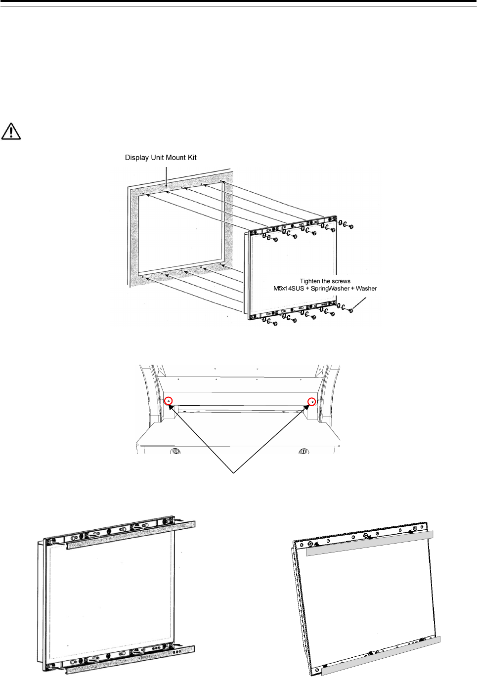
2) Install the Monitor Unit to the Display Unit Mount Kit with screws. Screws are attached to the Monitor Unit.
Screw: M5x14SUS + Spring washer + Washer (included in CWA-245/CWA-246/CWB-1594/CWB-1595)
Number of screw point: 26inch Monitor Unit(NWZ-208/NWZ-208-TP) - 10 points
19inch Monitor Unit(NWZ-207/NWZ-207-TP) - 6 points
Do not install in a position to close the vents of the monitor.
In case of the 26inch Monitor Unit
3) Remove the rear panel for wiring.
Remove
4) Insert the screw covers into the top and bottom spaces on the monitor.
Monitor unit(26inch) NWZ-208/NWZ-208-TP Monitor unit(19inch) NWZ-207/NWZ-207-TP
Installation of Monitor Unit ends above.
3 Installation of Display Unit > 3.4 Installation of Standard Equipment
3-31
3.4.2 Installation of Operation Unit (NCE-5625/CWB-1593/NCE-5605)
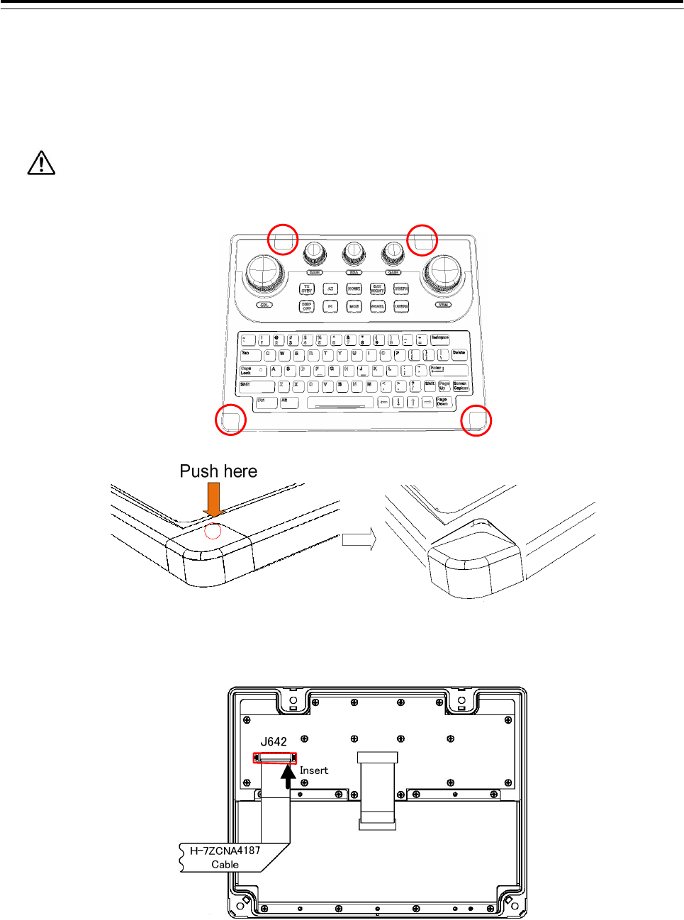
3.4.2.1 Installation of Keyboard Operation Unit (NCE-5625)
1) Remove the 4 screw covers from the KOPU-Keyboard Operation Unit by pushing the inside of the cover.
Do not remove the cover using a flat blade screwdriver. Because there is a possibility that the cover
is damaged.
2) Insert the W64: H-7ZCNA4187cable (included in the CMD-1106 in the NCE-5625) to the J642 connecter.
3 Installation of Display Unit > 3.4 Installation of Standard Equipment
3-32
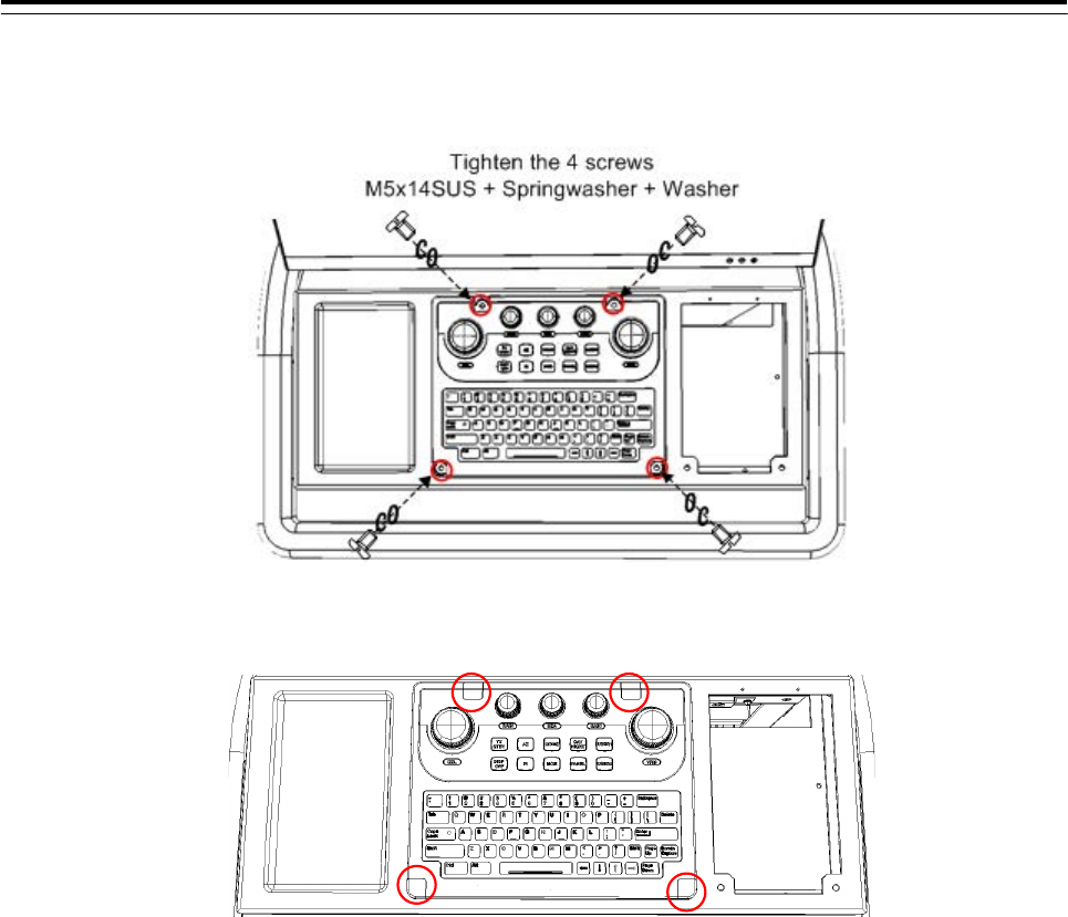
3) Install the KOPU to the Display Unit Mount Kit.
Screw: M5x14SUS + Spring washer + Washer (included in CWA-245/CWA-246/CWB-1596)
4) Insert the 4 screw covers into the original positions.
3 Installation of Display Unit > 3.4 Installation of Standard Equipment
3-33
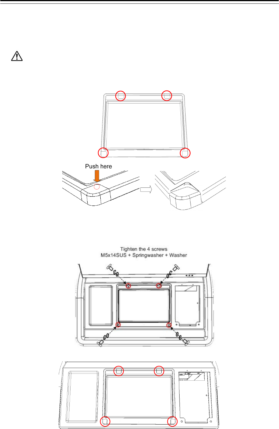
3.4.2.2 Installation of Large Tray (CWB-1593)
1) Remove the 4 screw covers from the Large Tray by pushing the inside of the cover.
Do not remove the cover using a flat blade screwdriver. Because there is a possibility that the cover
is damaged.
2) Install the Large Tray to the frame (CWA-245/CWA-246/CWB-1596).
Screw: M5x14SUS + Spring washer + Washer (included in CWA-245/CWA-246/CWB-1596)
3) Insert the 4 screw covers into the original positions.
3 Installation of Display Unit > 3.4 Installation of Standard Equipment
3-34
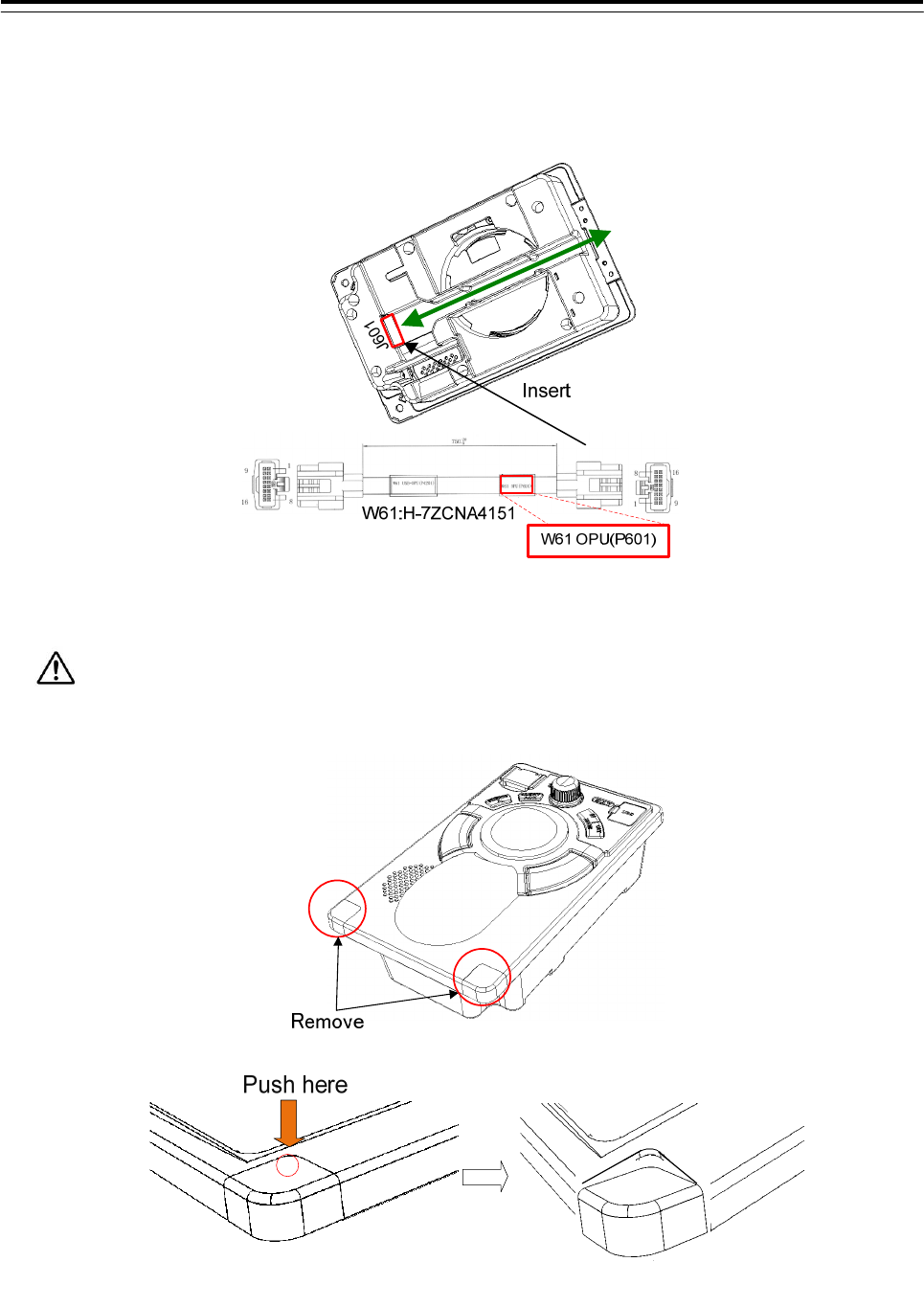
3.4.2.3 Installation of Trackball Operation Unit (NCE-5605)
1) Connect the W61: H-7ZCNA4151(included in CML-901) with the TOPU-Trackball Operation Unit.
After connecting, guide the cable in the groove.
2) Remove the 2 screw covers from the TOPU.
Remove the screw covers by pushing the inside of the cover.
3 Installation of Display Unit > 3.4 Installation of Standard Equipment
3-35
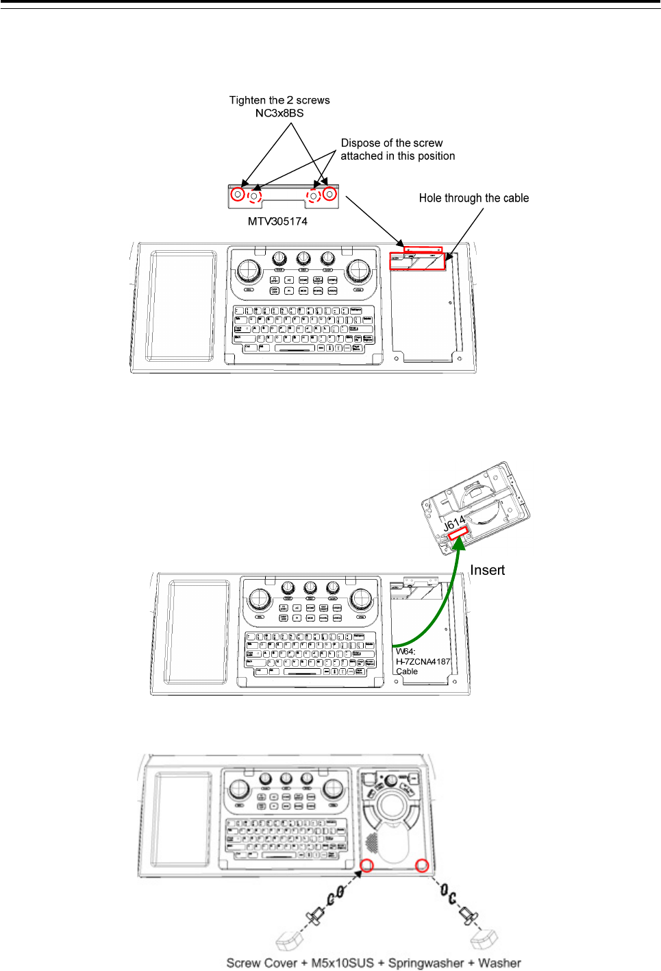
3) Install the TOPU bracket (MTV305174 included in TOPU) to the frame (CWA-245/CWA-246/CWB-1596).
Screw: NC3x8BS (included in CWA-245/CWA-246/CWB-1596)
4) In case of installation of Keyboard Operation Unit.
Connect the W64: H-7ZCNA4187 cable (connected with Chapter 3.4.2.1 Installation of Keyboard
Operation Unit) to J614 connector on TOPU.
5) Insert the TOPU as shown in the figure below. And Install the TOPU to the Frame.
The W61: H-7ZCNA4151 cable through the hole in the bottom of the frame.
3 Installation of Display Unit > 3.4 Installation of Standard Equipment
3-36
3.4.3 Installation of Central Control Unit (NDC-1590)
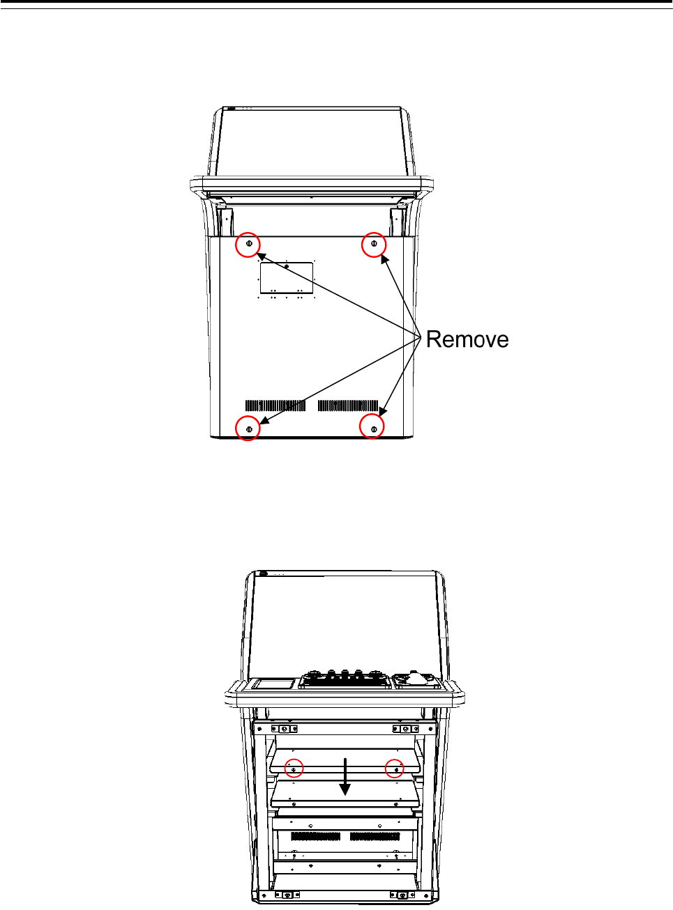
1) Remove the 4 screws of the front cover.
2) Remove the 2 screws that hold the upper shelf, and remove the shelf.
And then draw out forward and take out the upper shelf.
3 Installation of Display Unit > 3.4 Installation of Standard Equipment
3-37
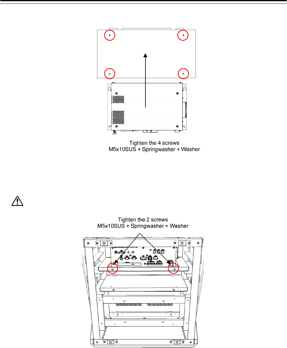
3) Install the CCU to the shelf. Refer to the figure below.
4) Insert the shelf installed CCU. And screw the shelf to the frame.
Make sure the shelf is not floating.
3 Installation of Display Unit > 3.4 Installation of Standard Equipment
3-38
3.4.4 Installation of Power Supply Unit (NBD-913)
1) Remove the 2 screws that hold the lower shelf, and remove the shelf.
And then draw out forward and take out the lower shelf.
2) Install the PSU-Power Supply Unit to the shelf. Refer to the figure below.
3) Insert the shelf installed PSU. And screw the shelf to the Frame.
Make sure the shelf is not floating.
3 Installation of Display Unit > 3.4 Installation of Standard Equipment
3-39
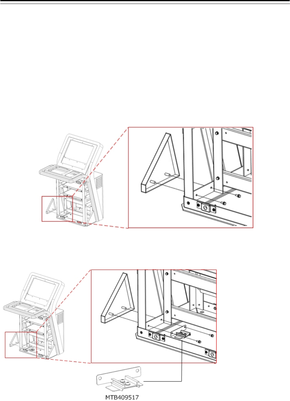
3.4.5 Installation of Relay Terminal (CQD-2312)
Attach the CQD-2312 Relay Terminal for distribute the AC/DC power.
When the NQA-2443 Sensor LAN SW or UPS, has been arranged, install the SENSOR LAN SW and UPS
before installing the Relay Terminal. For install the Relay Terminal, refer to the following procedure.
-3.5.3 Installation of Sensor LAN Unit
-3.5.4 Installation of UPS
1) Remove the 2 screws fixed to Display Unit Mount Kit(CWA-245/246). Refer to figure below for screw
position.
2) Fix the bracket for relay terminal mount(MTB409517) to Display Unit Mount Kit(CWA-245/246) use the
screws removed in the previous section
3 Installation of Display Unit > 3.4 Installation of Standard Equipment
3-40
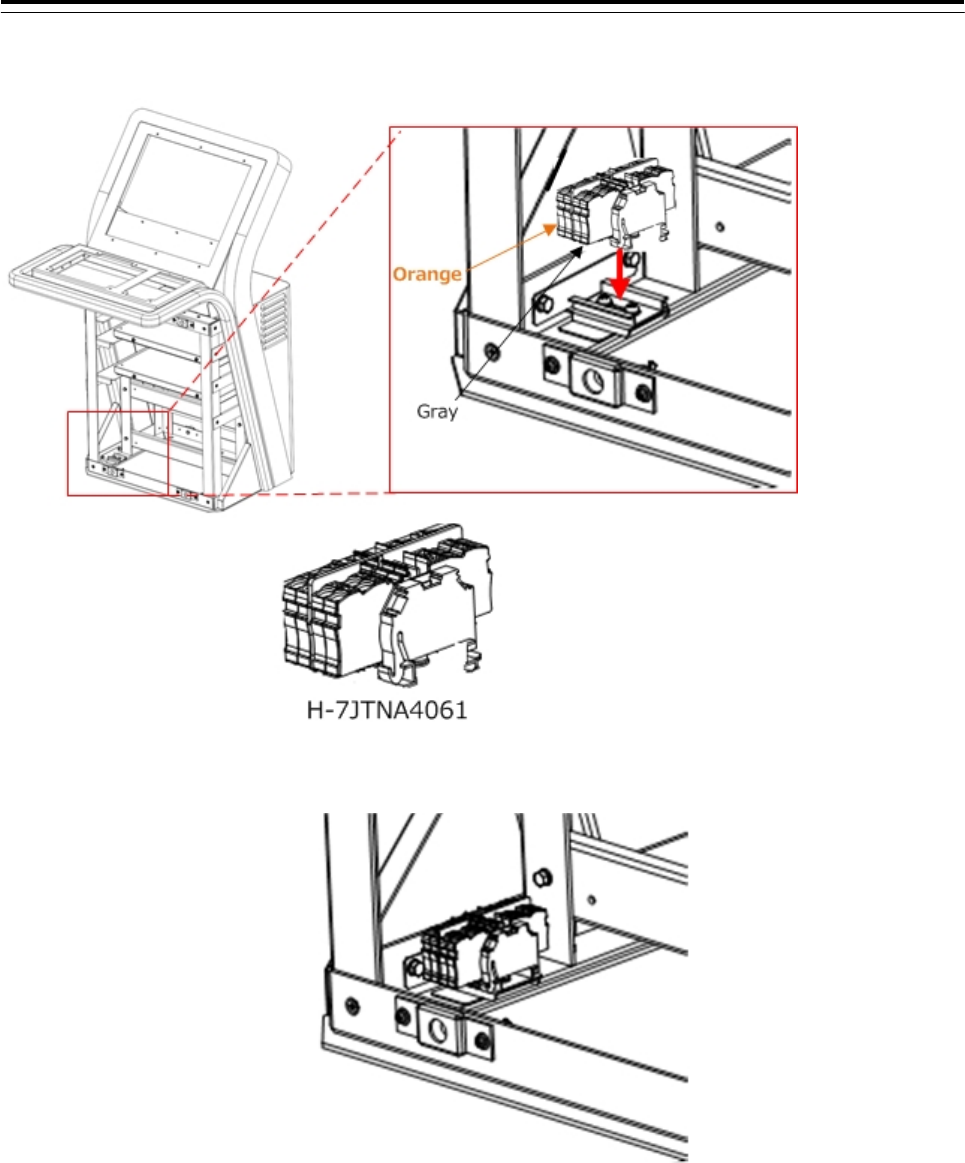
3) Attach the Relay terminal(H-7JTNA4061) to the DIN rail. Refer to figure below.
4) Make sure that Relay terminal is fixed as shown in the figure below.
The installation of Relay terminal ends above
3 Installation of Display Unit > 3.4 Installation of Standard Equipment
3-41
3.4.6 Connection of cables between unit
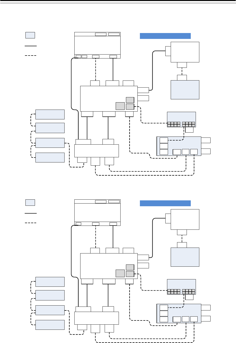
3.4.6.1 Wiring diagram
Option
Option wiring
Standard wiring NWZ-208
MNU
DVI
RGB_in
USB
RGB_out
DC AC
NDC-1590
CCU
J4101
DVI-MNU
J4118
USB_TP
J4202
SER-OPU
J4201
USB-OPU
J4203
RIF
J4204
PSU-CONT
J4301
PWR-PSU
J4205
RGB-OUT
NBD-913
PSU
J53
CONT
J52
OUT
J51
DC_SC
OUT
J50
AC_SC
OUT
NCE-5605
TOPU
NCE-5625
KOPU
NQE-1143
JB
J831
RIF
J8100
DC24V
J601
OPU
J614
KOPU
J642
KOPU
J8111
LAN
J839
DC
TB838
AC MTR
TB840
DC MTR
J4117
LAN1
J4122
LAN2
J4115
RADAR
NQA-2443
Sensor LAN SW
P90
DC24V
W71
7ZCNA4147
W73 7ZCNA4149
J8112
LAN
W64 7ZCNA4187
W61 7ZCNA4151
W75
BSUABFC210IV
W83
KB-STP-01LB
W53
7ZCNA4156A
W51
7ZCNA4154
W841
7ZCNA4164
W853
7ZCNA4160
W85
KB-STP-01LB
J837
48V
W851
7ZCNA4158
ME-MAX-NEF/
QUINT20A
QUINT-BAT/24DC/
3.4AH
QUINT-DC-UPS/
24DC/20
QUINT-PS/1AC/
24DC/20
TB1
AC DC
JMR-9200 series wiring
Fig 3-22: JMR-9200Series/JAN-9201/JAN-9202 Wiring Diagram
Option
Option wiring
Standard wiring NWZ-207
MNU
DVI
RGB_in
USB
RGB_out
DC
NDC-1590
CCU
J4101
DVI-MNU
J4118
USB_TP
J4202
SER-OPU
J4201
USB-OPU
J4203
RIF
J4204
PSU-CONT
J4301
PWR-PSU
J4205
RGB-OUT
NBD-913
PSU
J53
CONT
J52
OUT
J51
DC_SC
OUT
J50
AC_SC
OUT
NCE-5605
TOPU
NCE-5625
KOPU
NQE-1143
JB
J831
RIF
J8100
DC24V
J601
OPU
J614
KOPU
J642
KOPU
J8111
LAN
J839
DC
TB838
AC MTR
TB840
DC MTR
J4117
LAN1
J4122
LAN2
J4115
RADAR
NQA-2443
Sensor LAN SW
P90
DC24V
W71
7ZCNA4147
W73 7ZCNA4149
J8112
LAN
W64 7ZCNA4187
W61 7ZCNA4151
W75
BSUABFC210IV
W83
KB-STP-01LB
W53
7ZCNA4156A
W51
7ZCNA4154
W841
7ZCNA4164
W853
7ZCNA4160
W85
KB-STP-01LB
J837
48V
W851
7ZCNA4158
ME-MAX-NEF/
QUINT20A
QUINT-BAT/24DC/
3.4AH
QUINT-DC-UPS/
24DC/20
QUINT-PS/1AC/
24DC/20
TB1
AC DC
JMR-7200 series wiring
Fig 3-23: JMR-7200Series/JAN-7201/JAN-7202 Wiring Diagram
3 Installation of Display Unit > 3.4 Installation of Standard Equipment
3-42
3.4.6.2 Wiring of standalone type
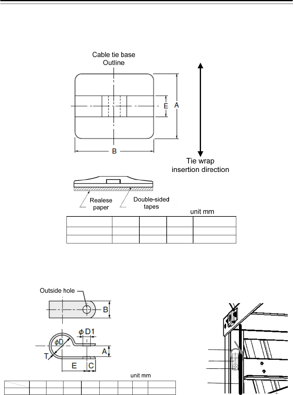
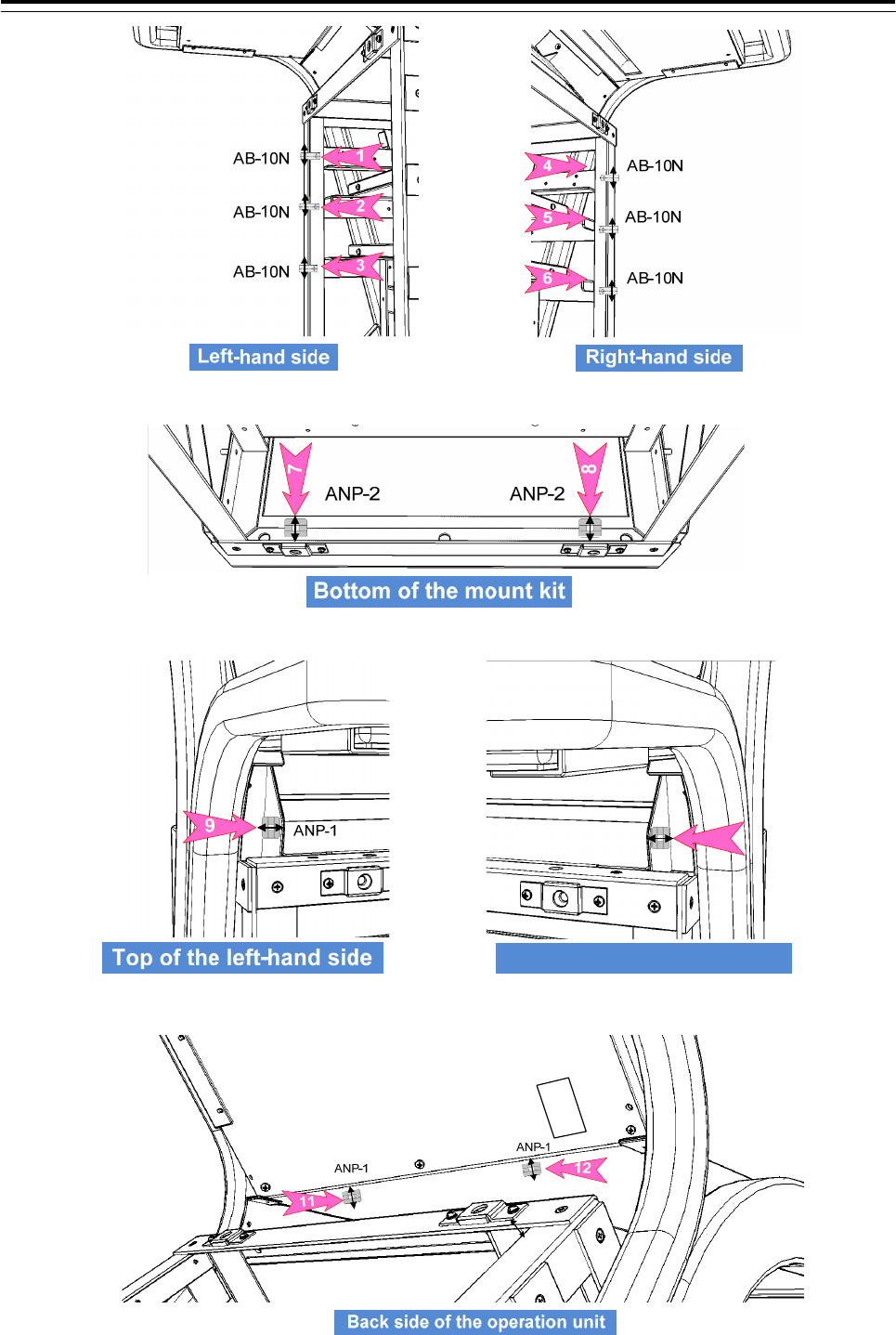
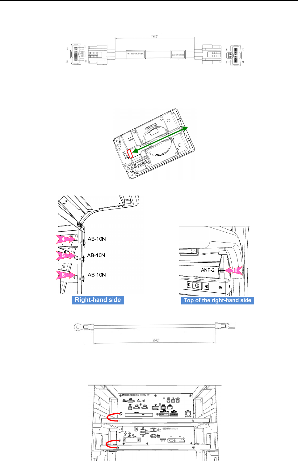
1) Attach the cable tie base(ANP-1, ANP-2) and nylon clip (AB-10N) to the 12 position shown in the figure
below.
Cable tie base A B E Cable tie type
ANP-1 20 20 7 T30R
ANP-2 25 30 8.2 T50R
Fig 3-24:Cable tie base ANP-1 and ANP-2
ABCφDφD1ETScrew
AB-10N 6.3 9.5 4.8 16 4.3 15.9 1.1 M4×10
Cable
AB-10N
Cable tie
M4X10BS
Fig 3-25 Nylon Clip AB-10N
Use the nylon clip as a clamp base. Refer to the above diagram.
3 Installation of Display Unit > 3.4 Installation of Standard Equipment
3-43
Top of the right-hand side
10
ANP-2
3 Installation of Display Unit > 3.4 Installation of Standard Equipment
3-44
2) Connect the cable with the following procedure.
●For option wiring, refer to 3.5 Installation of Option Equipment.
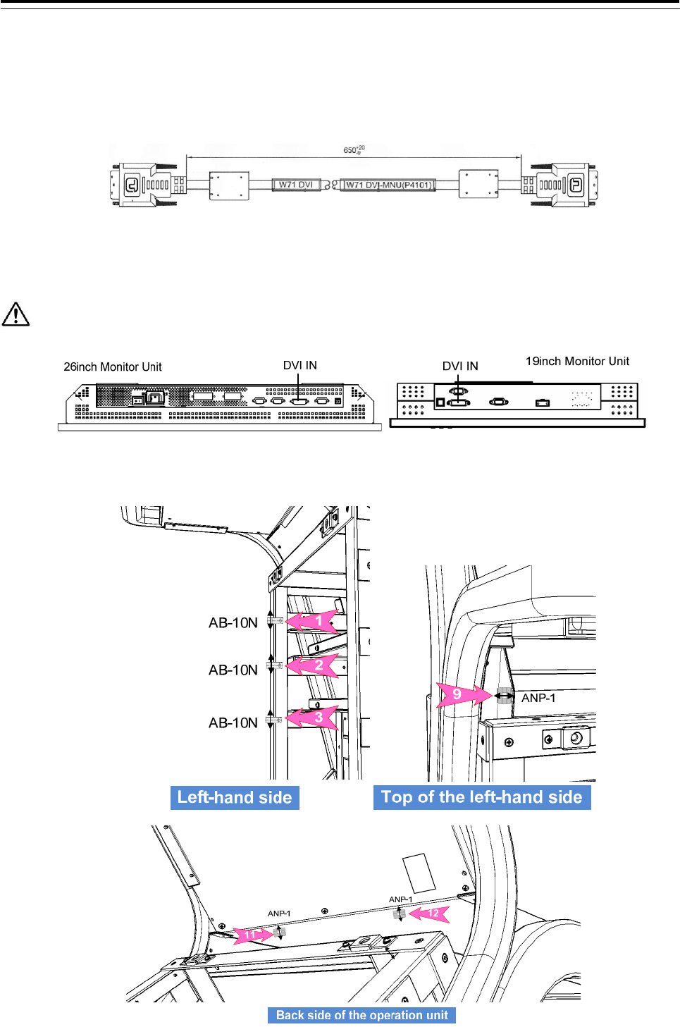
W71:H-7ZCNA4147(included in CML-901)
Connect the DVI connector on the Monitor unit and the J4101 connector on the CCU with W71:
H-7ZCNA4147 cable.
Be careful when connecting because it is easy to break the connection terminal of the DVI connector.
Wire the cable to pass through the nylon clip No.1 and the cable tie base No.9 and 11.
3 Installation of Display Unit > 3.4 Installation of Standard Equipment
3-45
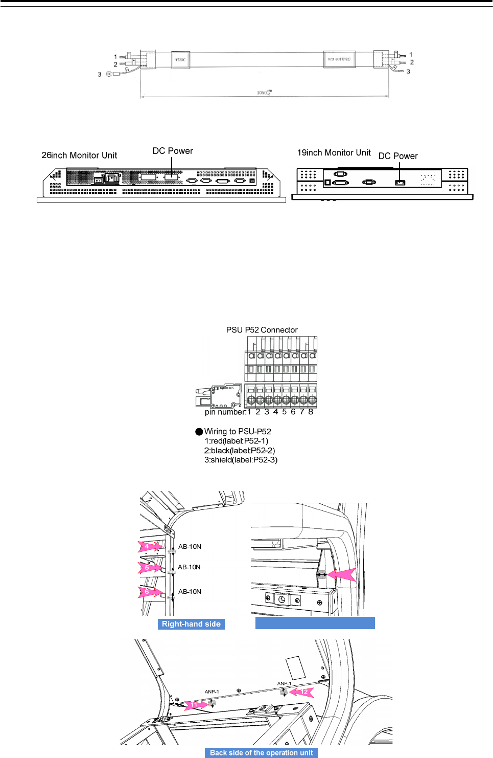
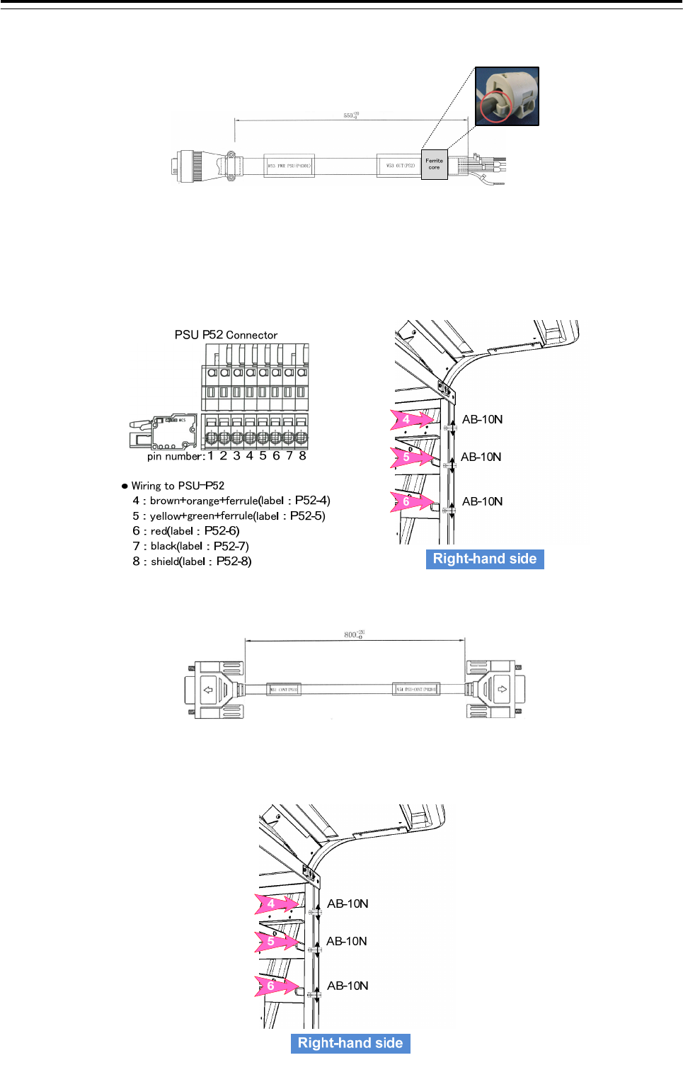
3) W73:H-7ZCNA4149(included in CML-901)
Connect the DC power connector on the monitor unit and the P52 connector on the PSU with W73:
H-7ZCNA4149 cable.
●Wiring to DC power connector on the Monitor
+: red(label: +24V)
-: black(label:24VE)
The polarities of the terminals are described near the connector.
The 26inch monitor unit DC power connector has 4 terminals. But only use pins No.2 and No.3.
Wire the cable to pass through the nylon clip No.4, 5 and the cable tie base No.10 and 12.
Top of the right-hand side
10
ANP-2
3 Installation of Display Unit > 3.4 Installation of Standard Equipment
3-46
4) W53:H-7ZCNA4156A(CML-901)
First, attach the ferrite core FL1:GTFC23-11-14 (included in CML-901) to the position shown in the figure
above. After that, fix in the cable tie (included in CML-901).
Second, Connect the J4301 connector on the CCU and the P52 connector on the PSU with the W53:
H-7ZCNA4156A cable.
Wire the cable to pass through the nylon clip No.5 and 6.
5) W51:H-7ZCNA4154(CML-901)
Connect the J4204 connector on the CCU and the P53 connector on the PSU with the W51:
H-7ZCNA4154 cable.
Wire the cable to pass through the nylon clip No.4, 5 and 6.
3 Installation of Display Unit > 3.4 Installation of Standard Equipment
3-47
6) W61:H-7ZCNA4151(CML-901)
Connect the J601 connector on the TOPU and the J4201 connector on the CCU with the W61:
H-7ZCNA4151 cable.
TOPU J601 Connector
Wire the cable to pass through the nylon clip No.4 and the cable tie base No.10.
7) W90/91:H-7ZCNA4214(CML-901)
Connect the FG terminal of the CCU/PSU and the frame with the W90/W91: H-7ZCNA4214 cable.
Y terminal :Frame side
Round terminal :CCU/PSU FG terminal
3 Installation of Display Unit > 3.4 Installation of Standard Equipment
3-48
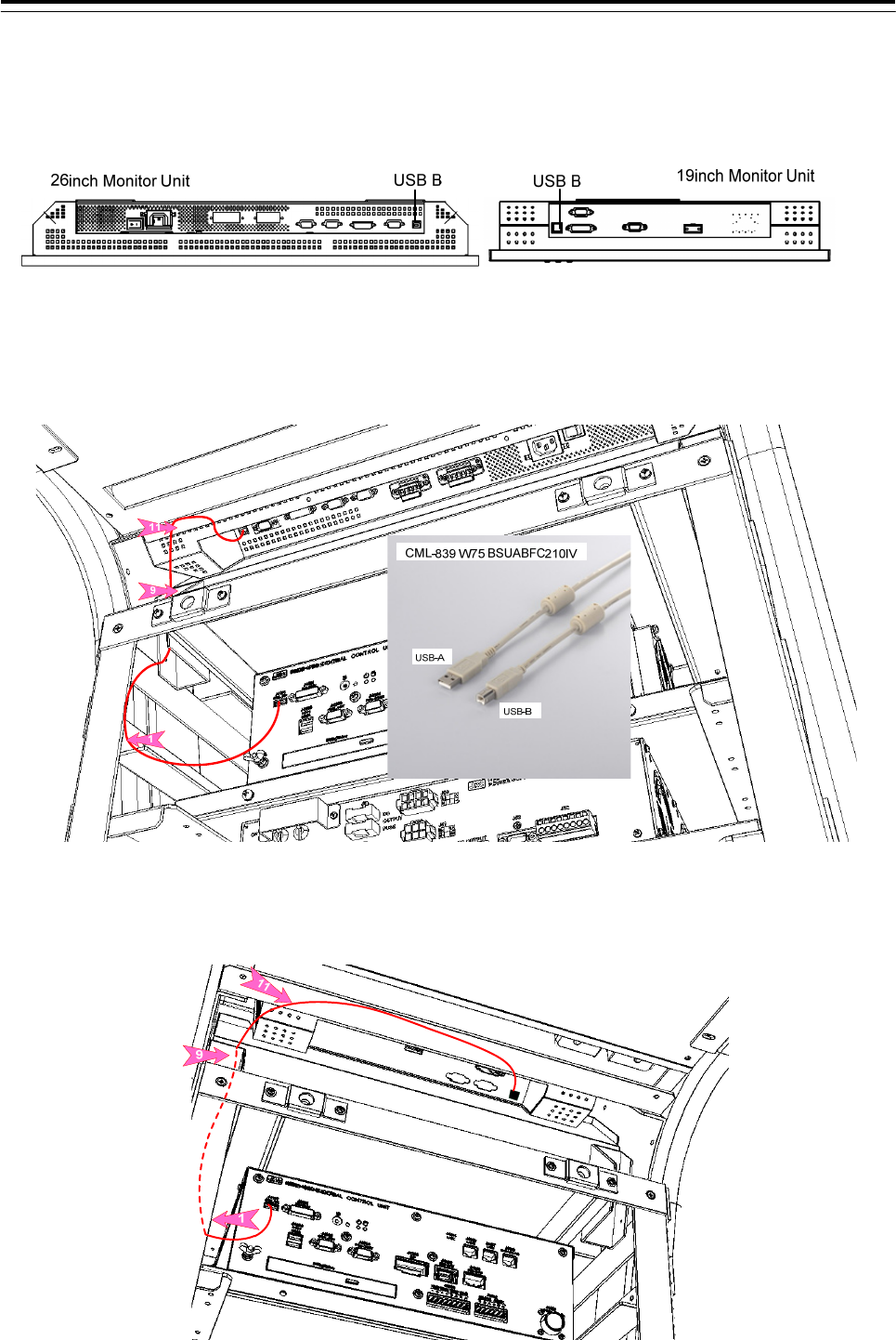
8) When installing touch panel unit(NWZ-208-TP, NWZ-207-TP)
Connect the USB-B connector on the monitor unit and J4118 USB-A connector on the CCU with CML-839
W75:BSUABFC201IV cable.
Wire the cable to pass through the nylon clip No.1 and the cable tie base 9 and 11.
26inch touch panel monitor unit
19inch touch panel monitor unit
3 Installation of Display Unit > 3.4 Installation of Standard Equipment
3-49
9) Fasten the cable using the T30R/T50R cable tie to the cable tie base.
ANP-1: Use the T30R
ANP-2: Use the T50R
AB-10N: No.1 – Use the T30R
No.4,5,6 – Use the T50R
Use the nylon clip as a clamp base. Do not use through the cable.
If installing the Option unit, should fasten the cable after installed the option unit.
Be careful so that the cables are not stretched.
Fold in the cable length is left over.
Don't forget the screw lock of the connector H-7ZCNA4147/4149/4154/4156A, because these
connectors are screw locking type connector.
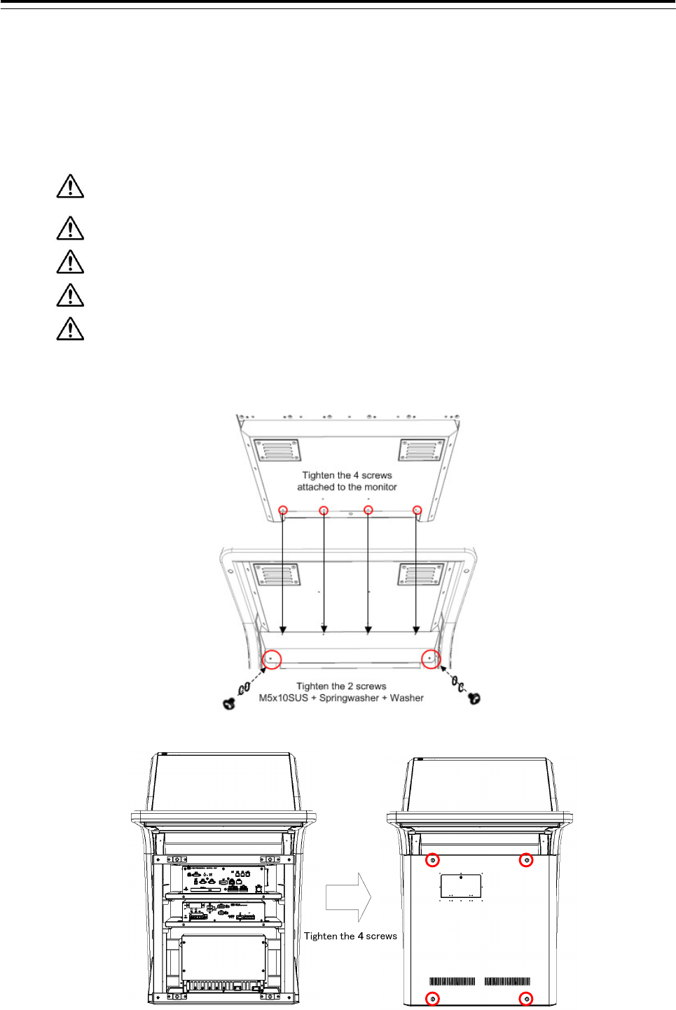
10) Install the front cover and rear cover.
3 Installation of Display Unit > 3.4 Installation of Standard Equipment
3-50
3.4.6.3 Wiring of Desktop type
1) Connect the cable with the following wiring diagram and procedure.
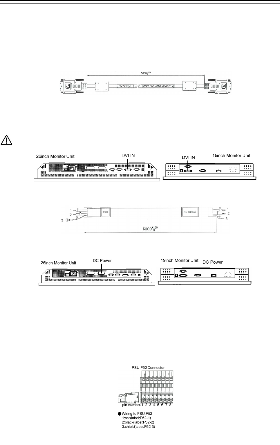
●For option wiring, refer to 3.5 Installation of Option Equipment.
W72:H-7ZCNA4148(CML-901-F)
Connect the DVI connector on the Monitor unit and the J4101 connector on the CCU with W71:
H-7ZCNA4148 cable.
Be careful when connecting because it is easy to break the connection terminal of the DVI connector.
2) W74:H-7ZCNA4150(CML-901-F)
Connect the DC power connector on the Monitor unit and the P52 connector on the PSU with W74:
H-7ZCNA4150 cable.
●Wiring to DC power connector on the Monitor
+: red(label: +24V)
- : black(label:-24V)
The polarities of the terminals are described near the connector.
The 26inch monitor unit DC power connector has 4 terminals. But only use pins No.2 and No.3.
3 Installation of Display Unit > 3.4 Installation of Standard Equipment
3-51
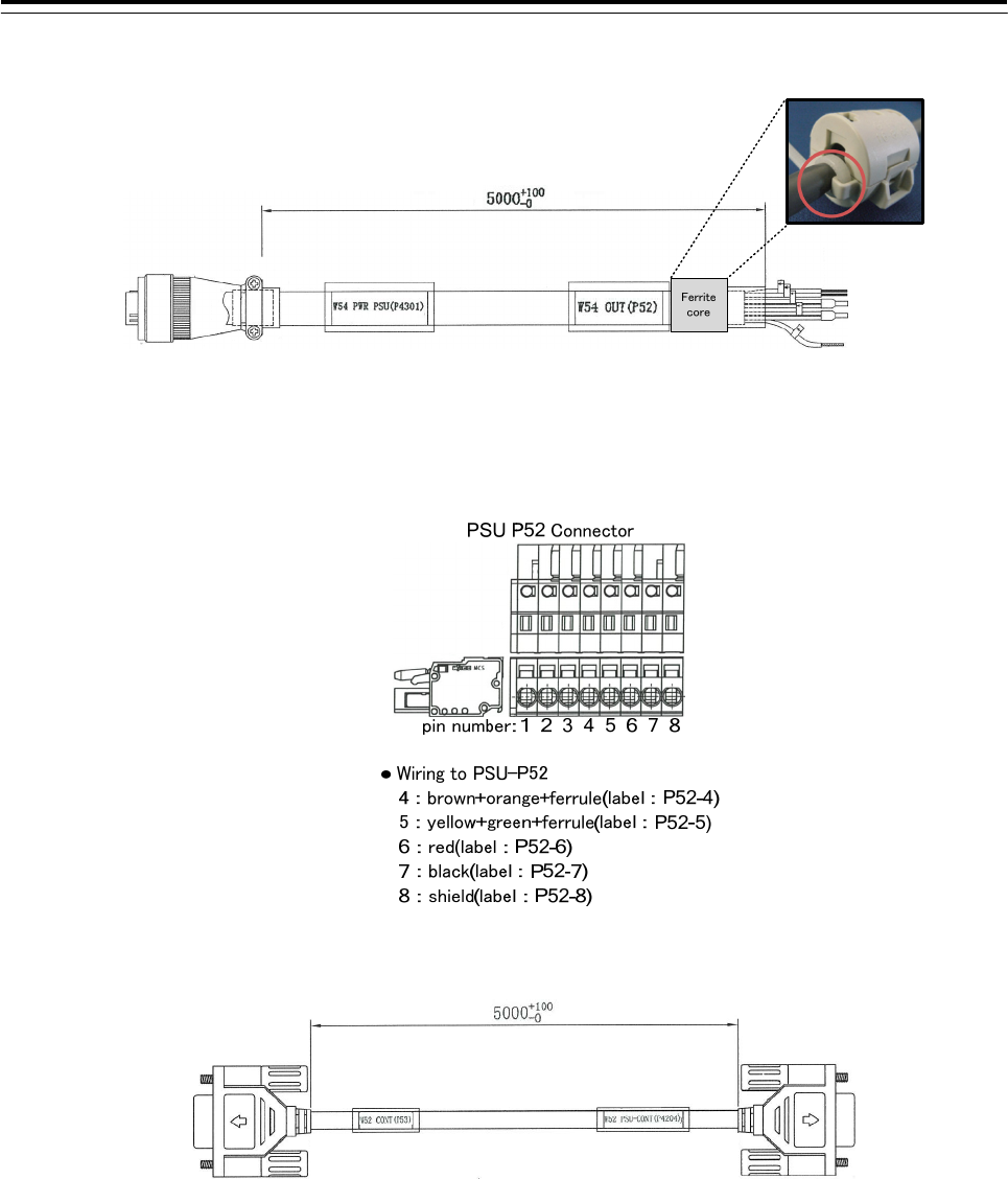
3) W54:H-7ZCNA4157A(CML-901-F)
First, attach the ferrite core FL1:GTFC23-11-14 (included in CML-901-F) to the position shown in the
figure above. After that, fix the ferrite core with cable tie (included in CML-901-F).
Second, Connect the J4301 connector on the CCU and the P52 connector on the PSU with the W54:
H-7ZCNA4157A cable.
4) W52:H-7ZCNA4155(CML-901-F)
Connect the J4204 connector on the CCU and the P53 connector on the PSU with the W52:
H-7ZCNA4155 cable.
3 Installation of Display Unit > 3.4 Installation of Standard Equipment
3-52
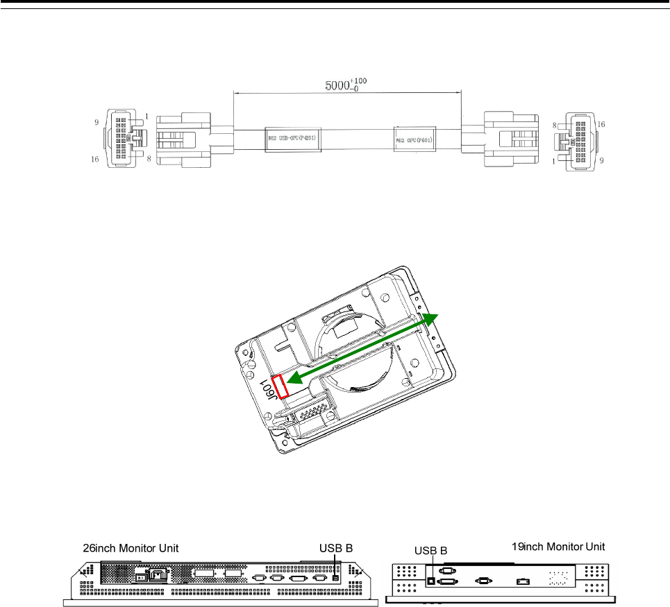
5) W62:H-7ZCNA4152(CML-901-F)
Connect the J601 connector on the TOPU and the J4201 connector on the CCU with the W62:
H-7ZCNA4152 cable.
TOPU J601 Connector
6) When installing touch panel unit(NWZ-208-TP, NWZ-207-TP)
Connect the USB-B connector on the monitor unit and J4118 USB-A connector on the CCU with CML-839
W75:BSUABFC201IV cable.
3 Installation of Display Unit > 3.4 Installation of Standard Equipment
3-53
3.4.7 Wiring for Relay Terminal
CQD-2312 Relay Terminal distribute the AC/DC power to the each unit. Wire rod for distribute is attached to
the Relay terminal. Process the cable. Refer to the following procedure.
3.4.7.1 Processing of wire rod
1) NBD-913 Power Supply Unit – wire rod for AC power
Cut the 2-core vinyl cab tire cable(VCT-2C-70/0.32) to length of the following. Remainder of this cable is not
required. Please dispose it.
2) NBD-913 Power Supply Unit – wire rod for DC power
Cut the white vinyl cable(250V-HV-37/0.26(9)) and black vinyl cable(250V-HV-37/0.26-(0)) to length of the
following.
Remainder of this cable to be used as AC/DC power cable for option unit(Serial LAN interface
circuit, Sensor LAN SW, UPS). Process to cut so as not to waste. Do not dispose until all wiring is
complete.
3 Installation of Display Unit > 3.4 Installation of Standard Equipment
3-54
When CMH-2370 Serial LAN interface circuit is arranged
3) CMH-2370 Serial LAN interface circuit - wire rod for DC power
Cut the white vinyl cable(250V-HV-37/0.26(9)) and black vinyl cable(250V-HV-37/0.26-(0)) to length of the
following. This cable is remainder of previous section.
Remainder of this cable to be used as AC/DC power cable for option unit(Serial LAN interface
circuit, Sensor LAN SW, UPS). Process to cut so as not to waste. Do not dispose until all wiring is
complete.
3 Installation of Display Unit > 3.4 Installation of Standard Equipment
3-55
When NQA-2443 SENSOR LAN SW is arranged
4) CMH-2370 Serial LAN interface circuit - wire rod for DC power
Cut the white vinyl cable(250V-HV-37/0.26(9)) and black vinyl cable(250V-HV-37/0.26-(0)) to length of the
following. This cable is remainder of previous section.
Remainder of this cable to be used as AC/DC power cable for option unit(Serial LAN interface
circuit, Sensor LAN SW, UPS). Process to cut so as not to waste. Do not dispose until all wiring is
complete.
In case of the 26inch Display Unit Mount Kit(CWA-246)
In case of the 19inch Display Unit Mount Kit(CWA-245)
3 Installation of Display Unit > 3.4 Installation of Standard Equipment
3-56
When UPS is arranged
5) UPS - wire rod for DC power output
CMH-2370 Serial LAN interface circuit - wire rod for DC power
Cut the white vinyl cable(250V-HV-37/0.26(9)) and black vinyl cable(250V-HV-37/0.26-(0)) to length of the
following. This cable is remainder of previous section
Remainder of this cable to be used as AC/DC power cable for option unit(Serial LAN interface
circuit, Sensor LAN SW, UPS). Process to cut so as not to waste. Do not dispose until all wiring is
complete.
6) UPS - wire rod for AC power input
Cut the 3-core vinyl cab tire cable cable(250V-HV-37/0.26(9)) and black vinyl cable(250V-HV-37/0.26-(0)) to
length of the following. Crimp the crimp terminal to white cable at terminal block side. Remainder of this cable
is not required. Please dispose it.
3 Installation of Display Unit > 3.4 Installation of Standard Equipment
3-57
3.4.7.2 Connection of Unit and Relay Terminal
Connect Relay terminal and each unit(NBD-913 Power Supply Unit, CMH-2370 Serial LAN interface circuit,
NQA-2443 SENSOR LAN SW, UPS). Use a wire obtained by processing in the previous section
CQD-2312 Relay Terminal Wiring diagram
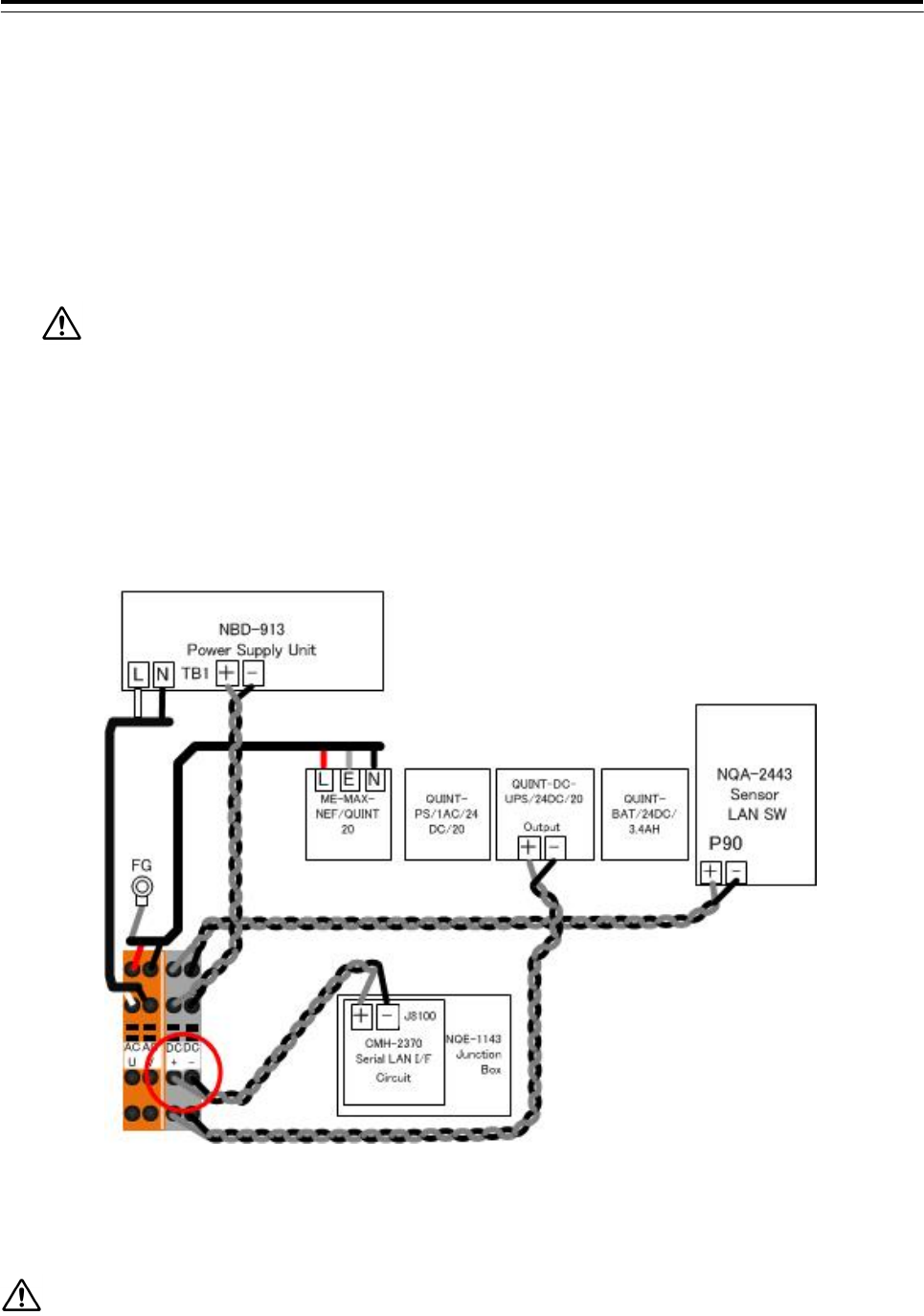
1) Wiring to the NBD-913 Power Supply Unit
- Wire the 2-core vinyl cab tire cable(VCT-2C-70/0.32) 550mm to the terminal block(TB1) L and N on
NBD-913 Power Supply Unit. L,U : White N,V : Black
- Wire the white vinyl cable(250V-HV-37/0.26(9)) and black vinyl cable(250V-HV-37/0.26-(0)) was cut to
700mm to the terminal block(TB1) + and – on NBD-913 Power Supply Unit.
+ : White, - : Black
Wire the cable to pass through the nylon clip No.3.
3 Installation of Display Unit > 3.4 Installation of Standard Equipment
3-58
2) When NQA-2443 SENSOR LAN SW is arranged
- Refer to the 3.5.3 Installation of Sensor LAN Unit for procedure of the installation.
- Wire the white vinyl cable(250V-HV-37/0.26(9)) and black vinyl cable(250V-HV-37/0.26-(0)) to the
terminal block(P90) + and – on NQA-2443 Power Supply Unit.
+ : White, - : Black
- Cable length
CWA-245 19inch Display Unit Mount Kit - 500mm
CWA-246 26inch Display Unit Mount Kit - 1200mm
When fix the cable, keep extra length so that there is no stress to terminal block(P90) for power
supply to the NQA-2443 SENSOR LAN SW.
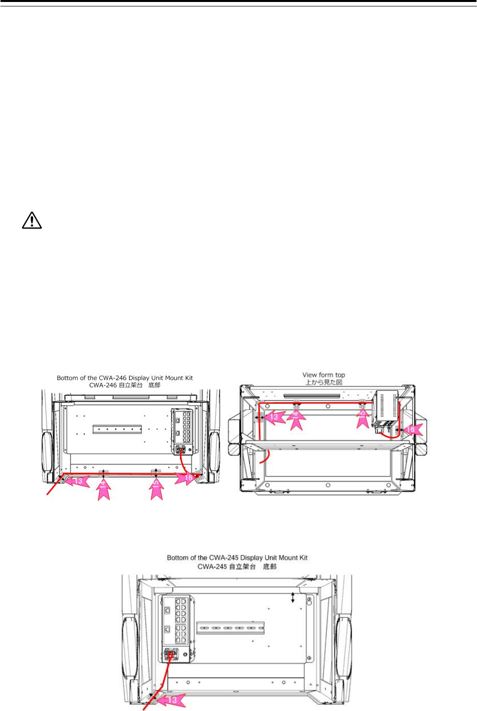
When 26inch Display Unit Mount Kit(CWA-246) is arranged
- Attach the cable tie base ANP-2 to the position of No.13, No.14, No.15 and No.16. And wire the cable.
(Refer to figure below)
- Fix the power supply cable of NQA-2443 SENSOR LAN SW to the ANP-2 by use the cable tie;T50R
When 19inch Display Unit Mount Kit(CWA-245) is arranged
- Attach the cable tie base ANP-2 to the position of No.13. And wire the cable.(refer to figure below)
3 Installation of Display Unit > 3.4 Installation of Standard Equipment
3-59
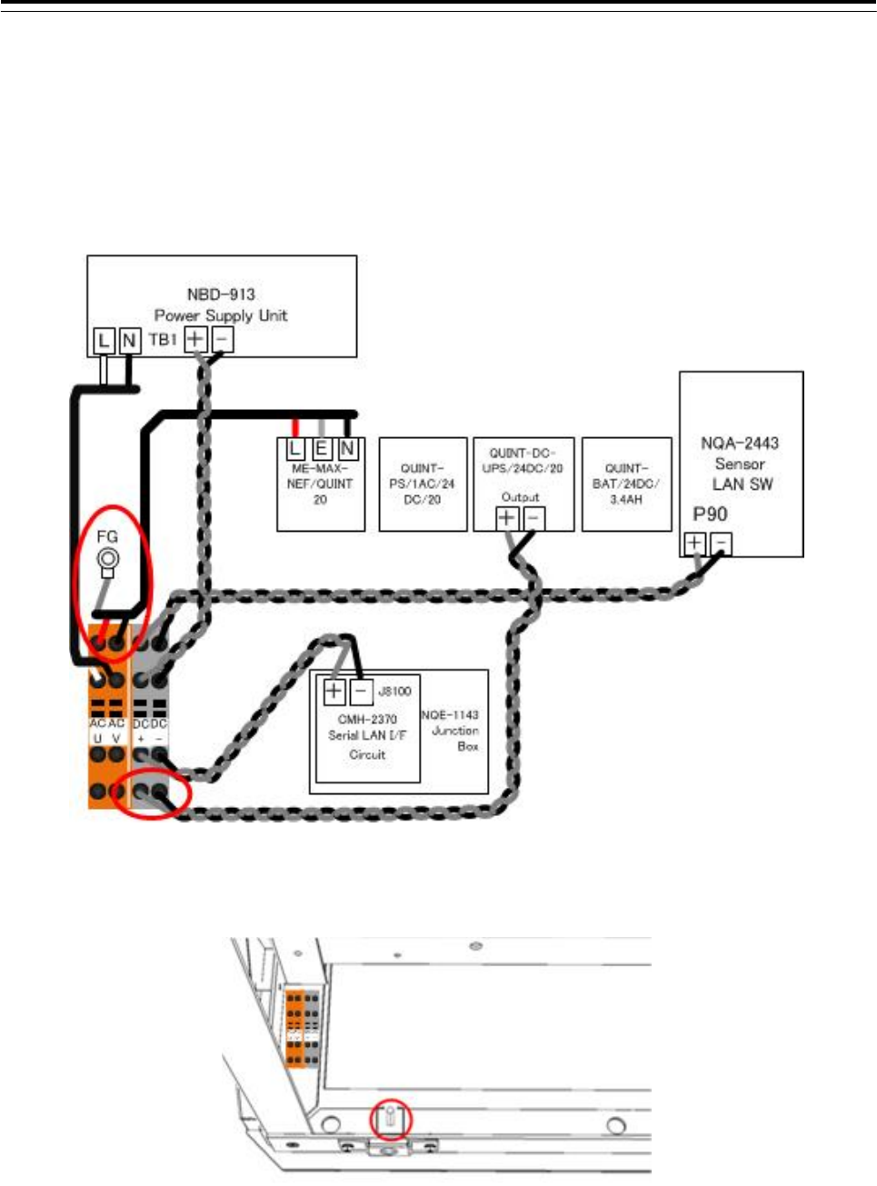
Wiring to the CQD-2312 Relay Terminal(Common in CWA-245 and CWA-246)
At the terminal block side, wire the cable to the position surrounded by the circle in the figure below.
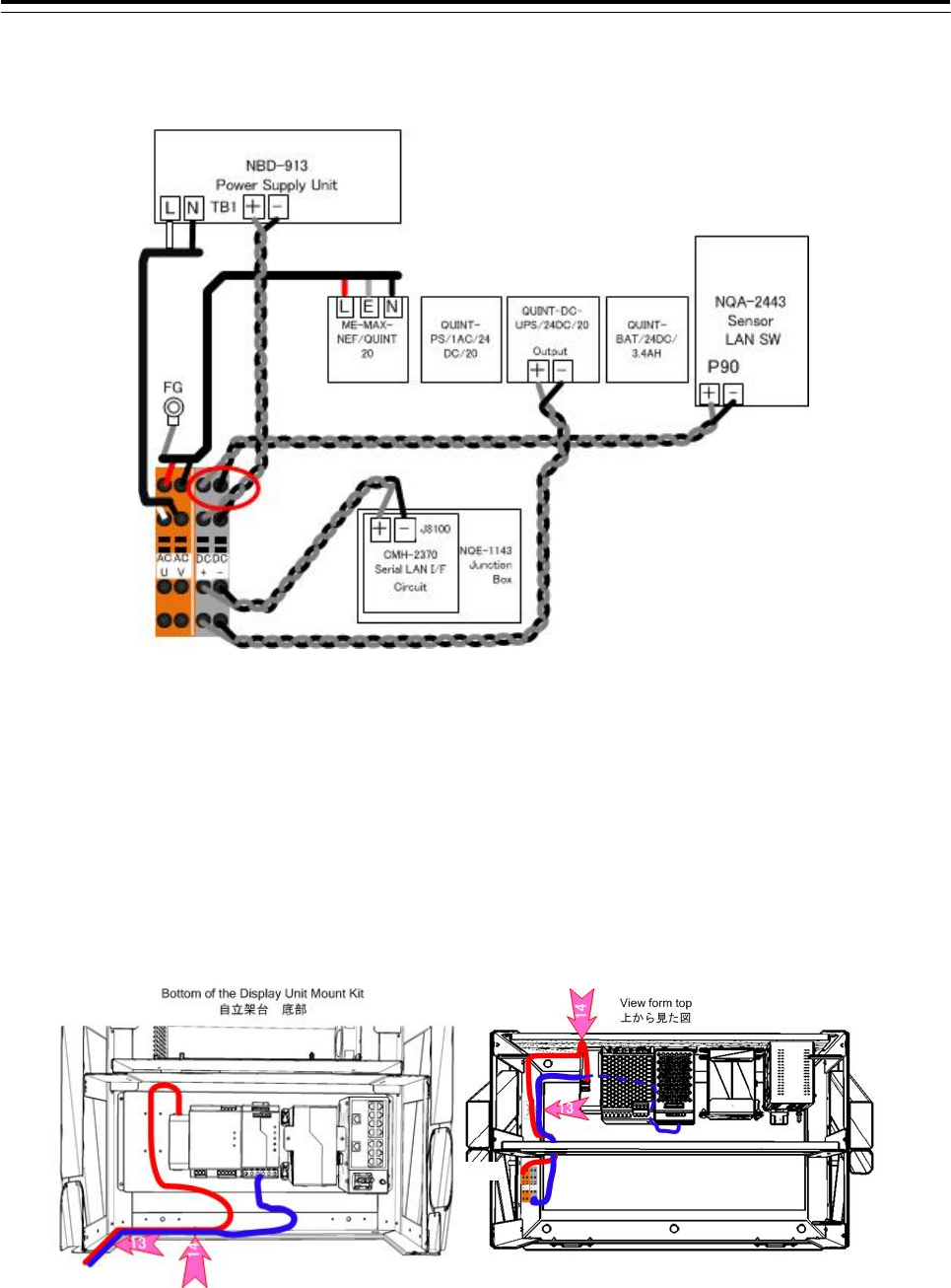
3) When UPS is arranged
- Refer to the 3.5.4 Installation of UPS for procedure of the installation.
- Wire the 3-core vinyl cab tire cable cable(250V-HV-37/0.26(9)) 1000mm to the terminal block L,E and N
on the ME-MAX-NEF/QUIT20.
L : Red, E : White, N : Black
- Wire the white vinyl cable(250V-HV-37/0.26(9)) 900mm and black vinyl cable(250V-HV-37/0.26-(0))
900mm to the output terminal block + and – on QUINT-DC-UPS/24DC/20.
+ : White - : Black
- Attach the cable tie base ANP-2 to the position of No.13 and No.14. And wire the cable.(refer to figure
above)
3 Installation of Display Unit > 3.4 Installation of Standard Equipment
3-60
- At the terminal block side, wire the cable to the position surrounded by the circle in the figure below.
AC-U : Red (VCT-3C-45/0.32)
AC-V : Black (VCT-3C-45/0.32)
DC+ : White (250V-HV-37/0.26-(9))
DC- : Black(250V-HV-37/0.26-(0))
Fix the crimped white cable to the thumbscrew.(Refer to figure below)
Bottom view(Left hand side)
3 Installation of Display Unit > 3.4 Installation of Standard Equipment
3-61
4) When CMH-2370 Serial LAN interface circuit is arranged
- Refer to the 3.5.1.1 Installation of Serial LAN Interface Circuit (SLC) and 3.5.1.5 Installation of JB for
procedure of the installation.
- Wire the white vinyl cable(250V-HV-37/0.26(9)) 700mm and black vinyl cable(250V-HV-37/0.26-(0))
700mm to the terminal block(J8100) 24V+ and 24V GND on CMH-2370 Serial LAN interface circuit.
24V+ : White 24V GND : Black
When coil is attached to the CMH-2370 Serial LAN interface circuit, Refe to the 3.5.1.5 Installation
of JB. And connect the power cable through the coil.
- At the terminal block side, wire the cable to the position surrounded by the circle in the figure below.
DC+ : White
DC- : Black
procedure of the main power supply connection, refer to the 3.13 Initialization for the specified model
Initialization for the specified model.
Before connecting the inboard power, please have finished all the necessary connections.
3 Installation of Display Unit > 3.5 Installation of Option Equipment
3-62
3.5 Installation of Option Equipment
3.5.1 Installation of Junction Box
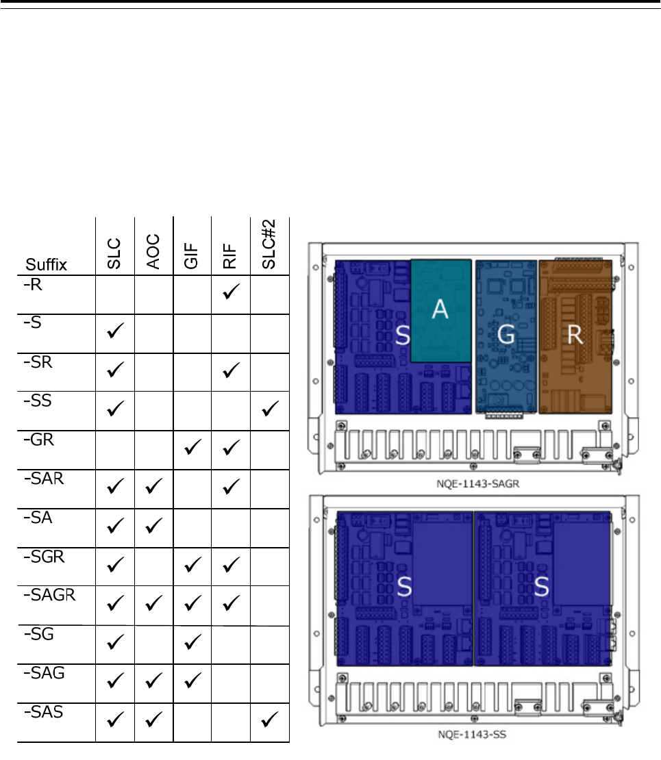
NQE-1143 Junction Box(JB) consists of interface boards that corresponds with the suffix.
Type of JB is shown in the table below.
The suffix is defined by the initials of the board from left when viewed from the front of the JB. Initials of the
board not installing are omitted.
Therefore, the type of JB :「NQE-1143-SAGR」is shown that JB consists of SLC, AOC, GIF and RIF.
3 Installation of Display Unit > 3.5 Installation of Option Equipment
3-63
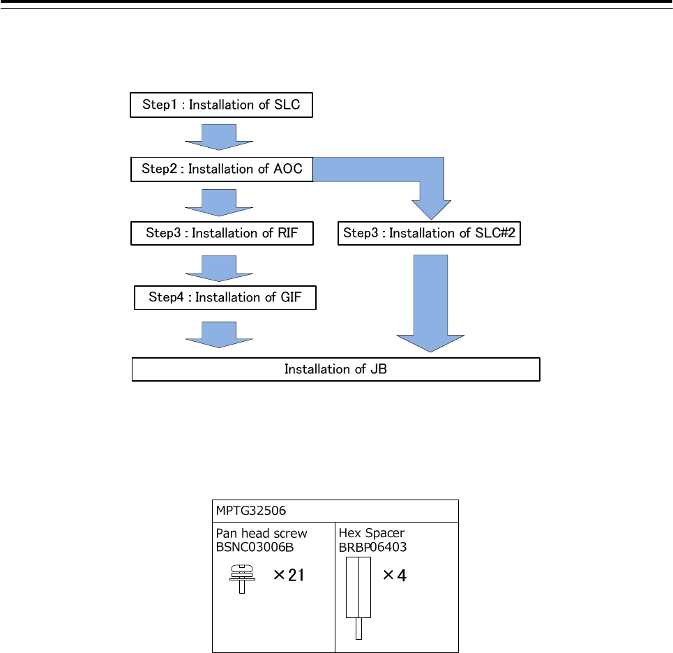
■Installation Procedure
Refer to the figure below. Skip the Installation procedure of the not installing board.
■Board installing parts
Install the boards using MPTG32506 attached to the JB frame.
3 Installation of Display Unit > 3.5 Installation of Option Equipment
3-64
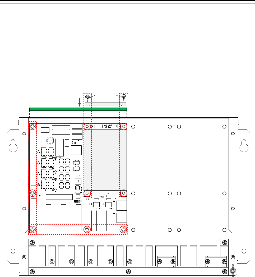
3.5.1.1 Installation of Serial LAN Interface Circuit (SLC)
1) Install the SLC to the position shown in the figure below using the 5 pan head screws (BSNC03006B) from
MPTG32506.
2) Install the shield case to the position shown in the figure below using the 4 pan head screws
(BSNC03006B) from MPTG32506.
Shiled case
SLC
Shiled case
2)
1)
PC810
Pan head screw
SLC
3 Installation of Display Unit > 3.5 Installation of Option Equipment
3-65
●When installing the two SLC to a junction box
1) Replace the hex spacer in JB shown in the figure below.
The hex spacer of the rightmost column is reuse.
2) Install the SLC#2 to the position shown in the figure below using the 9 pan head screws (BSNC03006B)
from MPTG32506.
■Installation of the attachment of the SLC
Note: If the coil with cable is not included, there is no need for the following procedure.
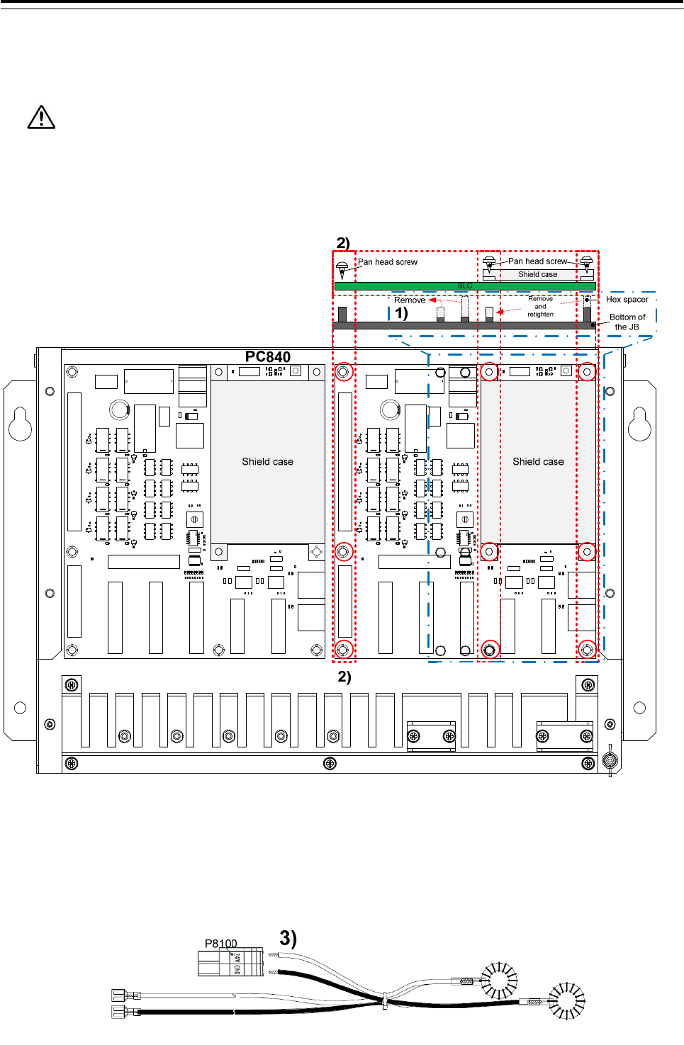
1) If the cable with coil in the figure below is included with the SLC,connect the coils to the P8100 terminal
block plug on the SLC.
SLC SLC#2
3 Installation of Display Unit > 3.5 Installation of Option Equipment
3-66
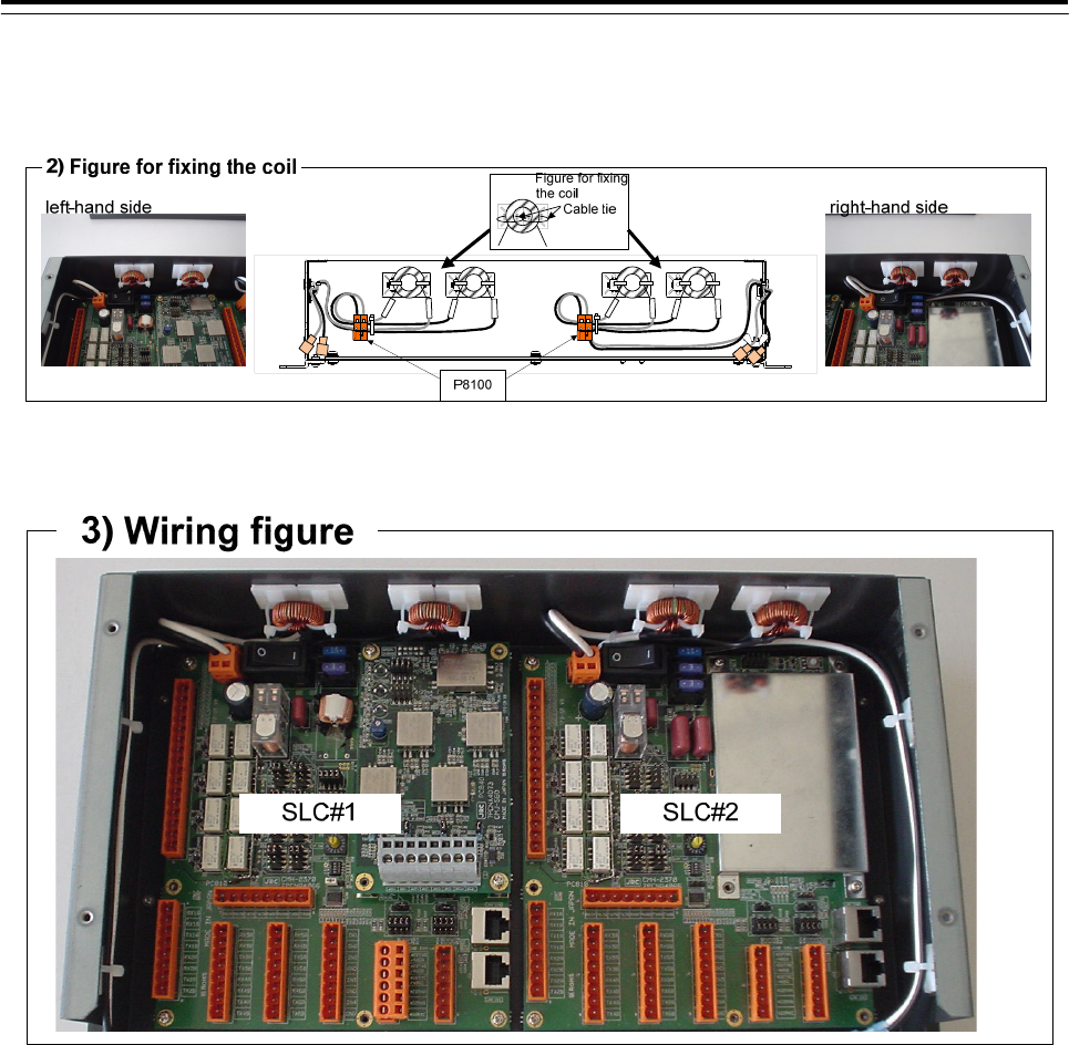
2) Fix the pair of coils to the cable tie base. Refer to figure for fixing the coil.
In case of SLC#2, attach as well another pair.
3) Wire the cable, refer to wiring figure below.
3 Installation of Display Unit > 3.5 Installation of Option Equipment
3-67
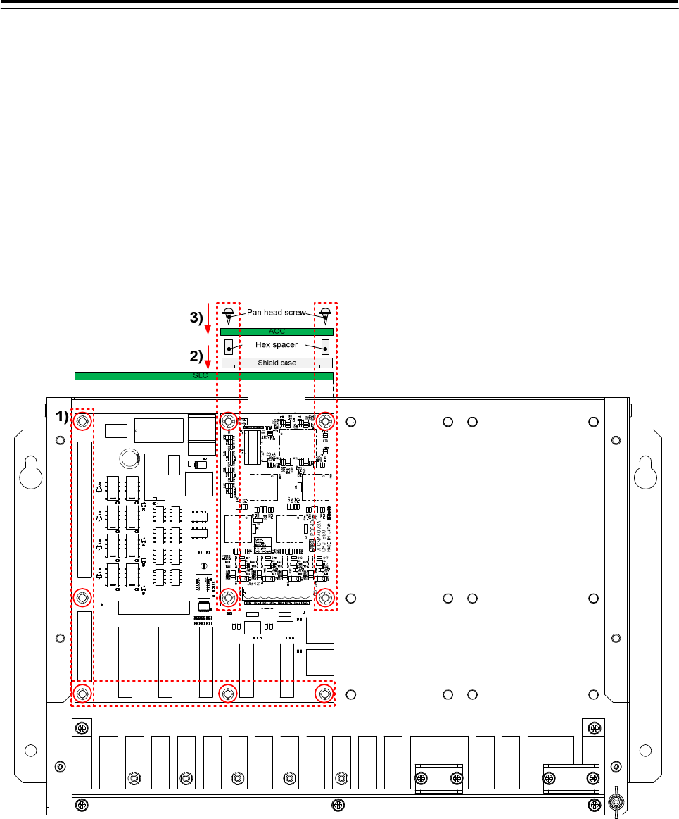
3.5.1.2 Installation of Analog Option Circuit (AOC)
1) Install the SLC(PC810) to the position shown in the figure below using the 5 pan head screws
(BSNC03006B) from MPTG32506.
2) Install the shield case to the position shown in the figure below using the 4 hex spacers (BRBP06403)
from MPTG32506.
3) Install the AOC(PC840) to the position shown in the figure below using the 4 pan head screws
(BSNC03006B) from MPTG32506.
SLC
AOC
3 Installation of Display Unit > 3.5 Installation of Option Equipment
3-68
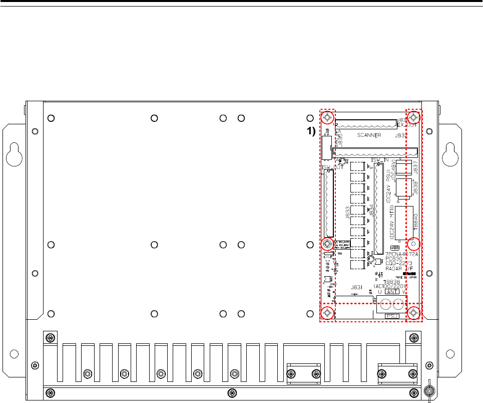
3.5.1.3 Installation of Radar Interface Circuit (RIF)
1) Install the RIF(PC830) to the position shown in the figure below using the 6 pan head screws
(BSNC03006B) from MPTG32506. Refer to Chapter 3.5.2 Connection of Display Unit and RIF for wiring.
RIF
3 Installation of Display Unit > 3.5 Installation of Option Equipment
3-69
3.5.1.4 Installation of Gyro Interface Circuit (GIF)
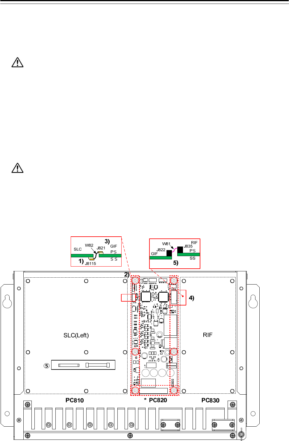
1) If there is the SLC(Left), W82:FF12-10N046XXA FFC cable(included in CMJ-554) should connect to the
J8115 connector on the SLC SS side. And lock the FFC connector.
Note insufficient insertion and inserted diagonally.
Make sure that the FFC connector is locked.
2) Install the GIF(PC820) to the position shown in the figure below using the 6 pan head screws
(BSNC03006B) from MPTG32506.
3) Connect the W82: FF12-10N046XXA FFC cable to the J821 connector on GIF. And lock the FFC
connector.
Note insufficient insertion and inserted diagonally.
Make sure that the FFC connector is locked.
4) Connect the W81: CP010391-20 ribbon cable(included in CMJ-554) to the J822 connector on the GIF.
And connect the W81 cable another end to the J835 connector on the RIF(PC830).
AR1
C1
C10
C11
C12
C14
C15
C16
C17
C18
C19
C2
C200
C201
C202
C21
C22
C23
C24
C25
C26
C27
C28C29
C3
C30
C32
C34
C35
C36
C37
C38
C39
C41
C42
C43
C44
C45
C46
C47
C48
C49 C50 C51
C52
C53
C54
C55
C56
C57
C58
C60
C61
C62
C63
C64
C65
C66 C67
C68
C69
C71
C72
C73
C74
C75
C76
C77 C78
C79
C8
C80
C81
C82
C83
C9
CD1
CD10
CD11
CD12
CD13
CD14
CD15
CD16 CD17
CD18
CD19
CD2
CD25 CD26CD27
CD3
CD30
CD32
CD33
CD34
CD35
CD36
CD37
CD38
CD39
CD4
CD40
CD42
CD43
CD44
CD45
CD46
CD47
CD5
CD54
CD59
CD6
CD7
CD8
CD9
F1 F2 F3 F4
FL1
FL2
FL3
FL5
FL6
FL7
FL8
IC1
IC10
IC11
IC13
IC14
IC15
IC3
IC4
IC5
IC6
IC7
IC8
IC9
J23J821
J822
J823
MP1
PHT2
PHT3 PHT4PHT5 PHT6PHT7PHT8
PHT9
PS1
R1
R10
R103
R104
R105
R106
R107
R11
R114
R116
R117
R118
R12
R120
R122
R123
R124
R125
R126
R13
R14
R15
R16
R17
R18
R19
R2
R20
R200
R201
R202
R203
R204
R205
R206
R207
R208
R209
R21
R210
R22
R23
R24
R27
R3
R34
R36
R37
R39
R4
R40
R401
R402
R403
R43
R44
R45
R46
R47
R48
R49
R5
R50
R501
R502
R51
R52
R53
R56 R57
R58R59
R6
R60
R61
R62
R63
R64
R65
R66
R67
R68
R69
R7
R70
R71
R72
R73
R74
R75
R76
R77
R78
R79
R8
R80
R81
R82
R83
R84
R85
R86
R87
R88
R89
R9
R90
R91
R92
R93
R94
R95
R96
R97
R98
S1
S2 S3
S4
TB1
TB10
TB19
TB2
TB3
TB4
TB401
TB402
TB403
TP1
TP10
TP100
TP11 TP12
TP13
TP14
TP15
TP16
TP17
TP18
TP19
TP2
TP20 TP21TP22 TP23TP24 T P25
TP26
TP27
TP28
TP29 TP3
TP30
TP31
TP32
TP33
TP34
TP35
TP36
TP4
TP5
TP6
TP7 TP8
TR1
TR4
TR5
TR6
TR7
TR8
TR9
XU1
3 Installation of Display Unit > 3.5 Installation of Option Equipment
3-70
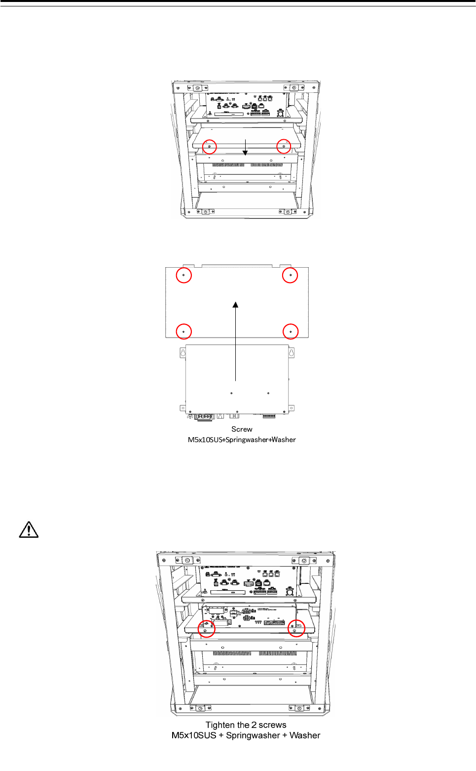
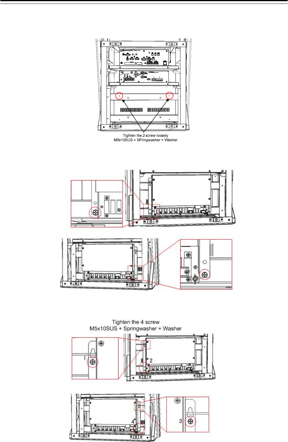
3.5.1.5 Installation of JB
1) Tighten the 2 screws(M5x10SUS + Spring washer + Washer) to the frame loosely.
2) Hook the JB to the frame with the 2 screws.
3) Install the JB to the frame.
3 Installation of Display Unit > 3.5 Installation of Option Equipment
3-71
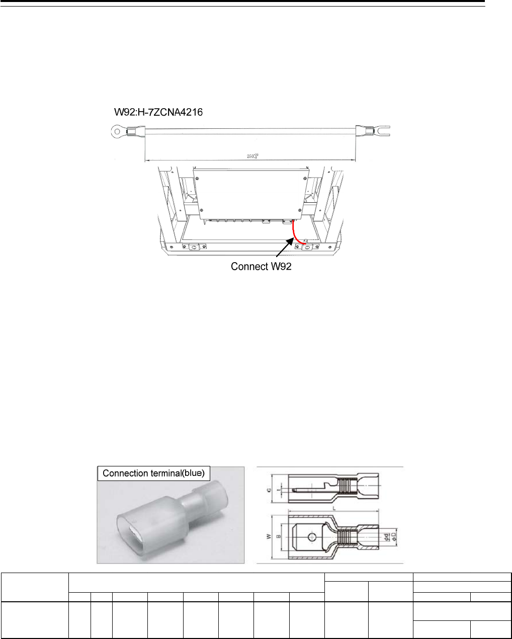
4) Connect the FG terminal of the JB to the frame.
Y terminal :Frame side
Round terminal :JB FG side
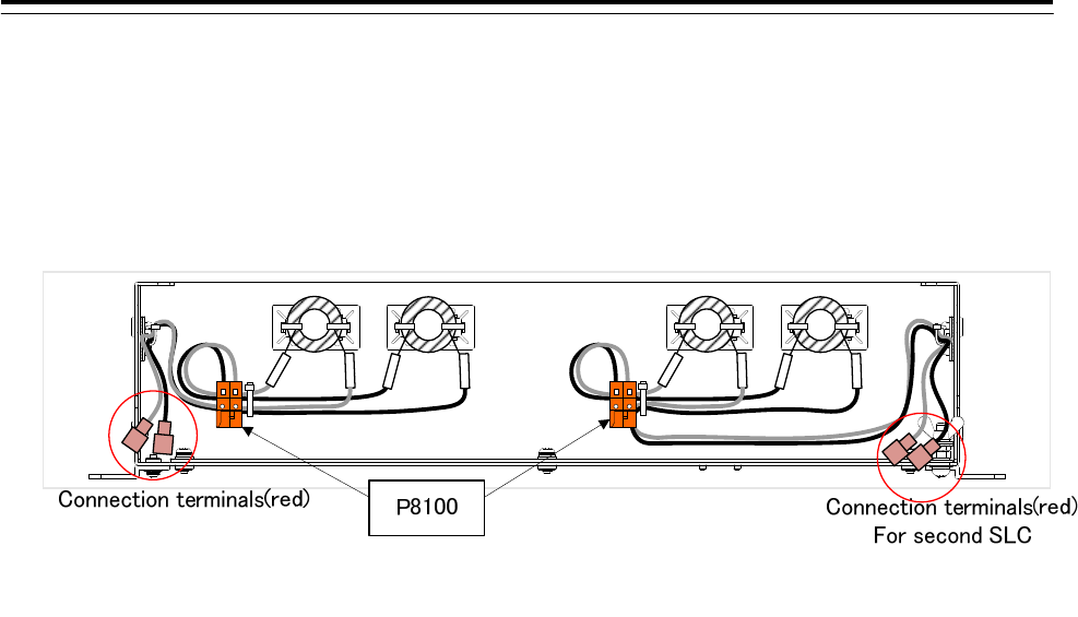
5) If the SLC is installed to the JB, connect the 24VDC power supply line to the reference to the figure
below.
■If the coil and connection terminal is attached to the JB.
There is a need to supply 24VDC through the coil. Please be wired to the following procedure.
Step1: Crimp the 2 connection terminals (blue) to the DC power cable(24VDC line and GND). Connection
terminals have been attached to the JB. If the second SLC is installed to the JB, crimp the connection
terminal as well.
B W t L φd φD G H TOOL BODY No. DIES No.
NA10
NA3
N10 12
N3 12
WIRE RANGE
AWG
STRANDED
mm
2
2.0 14.0
NH12
NH32
TOOL No.
TMEDN 630820-MA 6.35 10.3 0.8 22.0 2.55 4.5 6.4 10.0
HAND TOOL No.
DIMENSIONS mm
PART NUMBER
3 Installation of Display Unit > 3.5 Installation of Option Equipment
3-72
Step2: Connect the connection terminal (crimped in step1) to the JB side connection terminal(red).
●The polarity of the DC power cable of SLC
+: white
- : black
Step3: Please fix the DC power cable of SLC to the JB using the cable tie.
■If the coil and connection terminal are included with the JB
Please connect the DC24V supply line directly to the P8100.
●Terminal Assign of P8100
Terminal number 1:+24VDC (labeled with “24V”)
Terminal number 2:GND (labeled with “GND”)
3 Installation of Display Unit > 3.5 Installation of Option Equipment
3-73
3.5.2 Connection of Display Unit and RIF
3.5.2.1 Connection for standalone type
If the RIF is incorporated JB, connect the RIF and CCU. Either a cable is arranged by the scanner unit.
・ CML-836-AC
・ CML-836-DC
●When CML-836-AC has been arranged
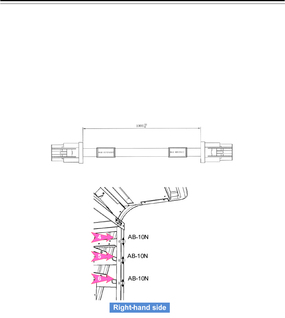
W841:H-7ZCNA4164(included in CML-836-AC)
Connect the J831 connector on the RIF to the J4203 on CCU by W841: H-7ZCNA4164.
Wire the cable to pass through the nylon clip No.5 and 6.
3 Installation of Display Unit > 3.5 Installation of Option Equipment
3-74
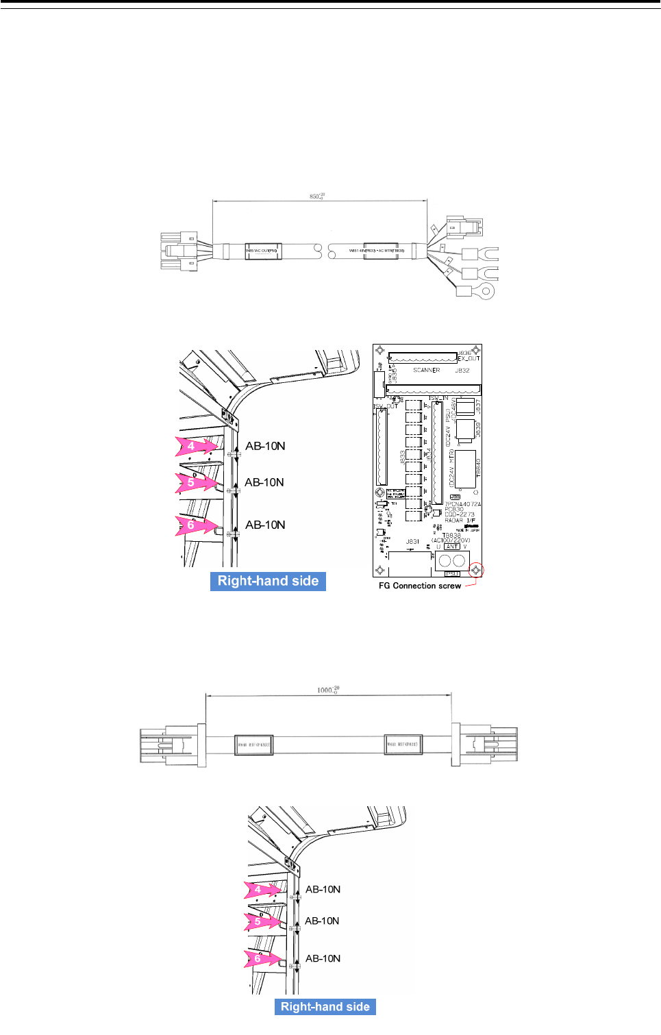
W851:7ZCNA4158(included in CML-836-AC)
・Connect the W851 cable connector labeled “P50” to the J50 connector on the PSU.
・Connect the cable labeled “P837” in the W851 cable to the J837 connector on the RIF.
・Connect the terminal labeled “U” in the W851 to the TB838 U terminal on the RIF.
・Connect the terminal labeled “V” in the W851 to the TB838 V terminal on the RIF.
・Co-tighten the terminal labeled “FG” in the W851 cable and FG connection screw on the RIF.
Wire the cable to pass through the nylon clip No.6.
●When CML-836-DC has been arranged
W841:H-7ZCNA4164(included in CML-836-DC)
Connect the J831 connector on the RIF to the J4203 on CCU by W841: H-7ZCNA4164.
Wire the cable to pass through the nylon clip No.5 and 6.