Japan Radio Co NKE2632 Solid State S-Band Marine Radar User Manual Installation Manual Part 7
Japan Radio Co Ltd. Solid State S-Band Marine Radar Installation Manual Part 7
Contents
- 1. Installation Manual Part 1
- 2. Installation Manual Part 2
- 3. Installation Manual Part 3
- 4. Installation Manual Part 4
- 5. Installation Manual Part 5
- 6. Installation Manual Part 6
- 7. Installation Manual Part 7
- 8. Installation Manual Part 8
- 9. Installation Manual Part 9
- 10. Installation Manual Part 10
- 11. Installation Manual Part 11
- 12. Instruction Manual Operation Part 1
- 13. Instruction Manual Operation Part 2
- 14. Instruction Manual Operation Part 3
- 15. Instruction Manual Operation Part 4
- 16. Instruction Manual Funtion Part 1
- 17. Instruction Manual Funtion Part 2
- 18. Instruction Manual Funtion Part 3
- 19. Instruction Manual Funtion Part 4
- 20. Instruction Manual Funtion Part 5
- 21. Instruction Manual Funtion Part 6
Installation Manual Part 7
5.Option Unit > 5.1 Installation of Interswitch Unit
5-1
5. Option Unit
5.1 Installation of Interswitch Unit
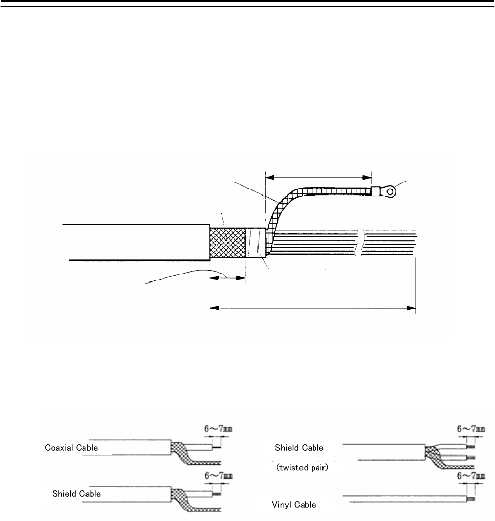
5.1.1 End processing of Interswitch cable(2695111153)
abt. 80 mm terminal
Inner Shield
Outer Shield
taping
1000 mm
Width for
clamping cable.
30 mm
2695110056
2695111153
abt.
abt.
Fig 5-1: Equipment cable end processing
Fig 5-2: End processing of each cable core
5.Option Unit > 5.1 Installation of Interswitch Unit
5-2
5.1.2 Connection of equipment cable
There is two type Interswitch(NQE-3141); NQE-3141-4A(4ch) and NQE-3141-8A(8ch).
Connection Procedure
1) Ground the earth plate to the hull ground.
2) Connect the Interswitch(NQE-3141) to the Radar I/F Circuit(CQD-2273) with the
2695111153 cable. Refer to Fig 5-5: NQE-3141-4A Inter-board connection diagram.
-When connect to the JAN-901/901M/701 and third-party ECDIS.
Connnect the input terminal : VD, TRG, BP, BZ(JAN-901/901M/701 and third-party ECDIS)
and output terminal : VDOUT, TRGOUT, BPOUT, BZOUT(NQE-3141).
- When connect to the JMA-9100/7100,JMA-5300MK2, JMA-900B.
Connect the VD, TRG, BP, BZ, PWR terminal on JMA-9100/7100,JMA-5300MK2,
JMA-900B and VD, TRG, BP, BZ, PWR terminal on the NQE-3141.
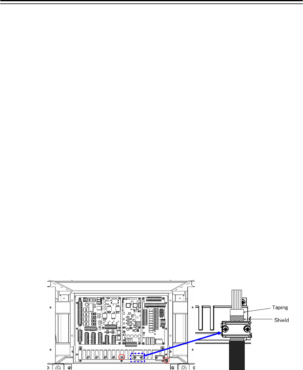
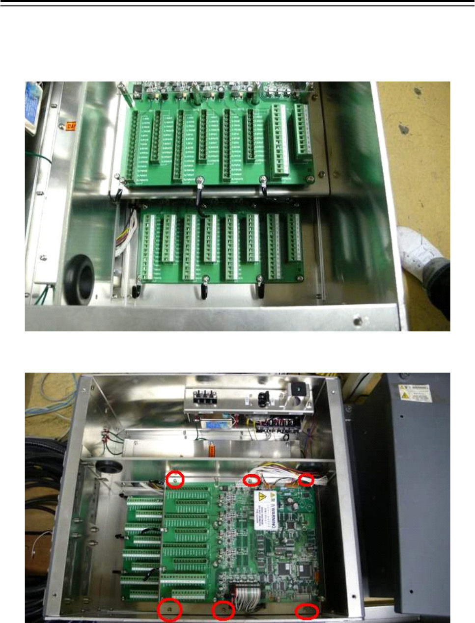
3) Refer to End processing of Interswitch cable(2695111153) for the end of processing of
Interswitch cable. When connect to the Radar I/F Circuit(CQD-2273) in the Junction
box(NQE-1143), fix the cable by the metal parts that surrounded by a dotted line.
Refer to the below detailed fixed position. And connect the shield of the cable to the
thumbscrew or hex spacer surrounded by the circle. (Recommended crimp terminal is V5.5)
Fig 5-3 Way of fixing and grounding(2695111153)
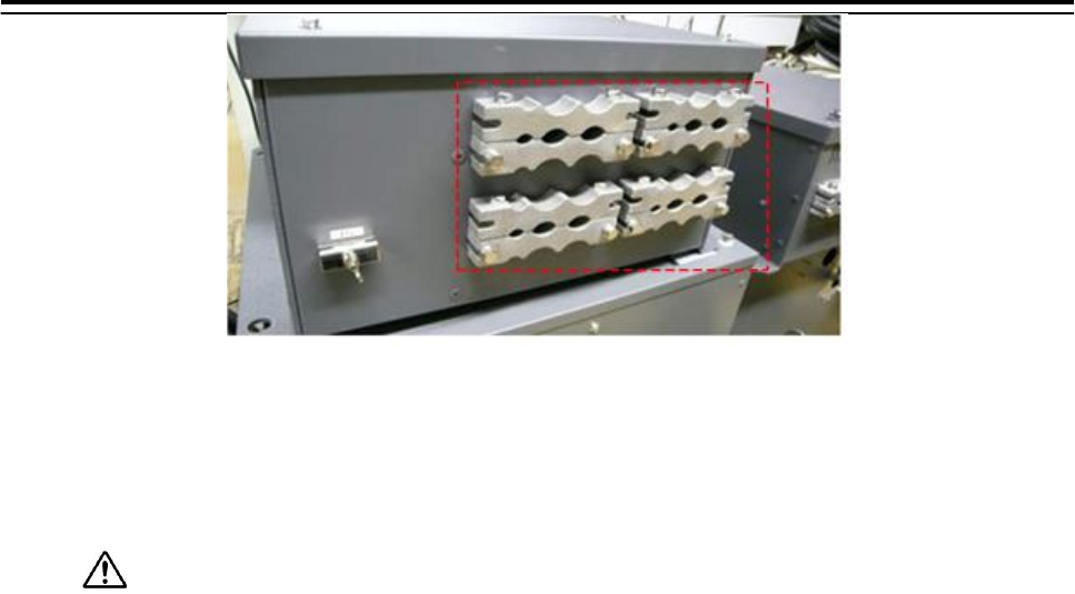
When connect to the interswitch unit, fix the shield portion of the cable by the metal parts
that surrounded by the dotted line.
5.Option Unit > 5.1 Installation of Interswitch Unit
5-3
Fig 5-4 Cable inlet of the NQE-3141-8A
So that the braided shield is not shorted to the power supply terminal block, please
insulate the cable and fix with cable tie. Please put the Extra length of the cable to the
bottom of the display unit so that the not shorted to the UPS or SENSOR LAN switch
unit.
4) After the installation is finished, refer to the 5.1.6 Confirmation after installation and
check the operation.
5.Option Unit > 5.1 Installation of Interswitch Unit
5-4
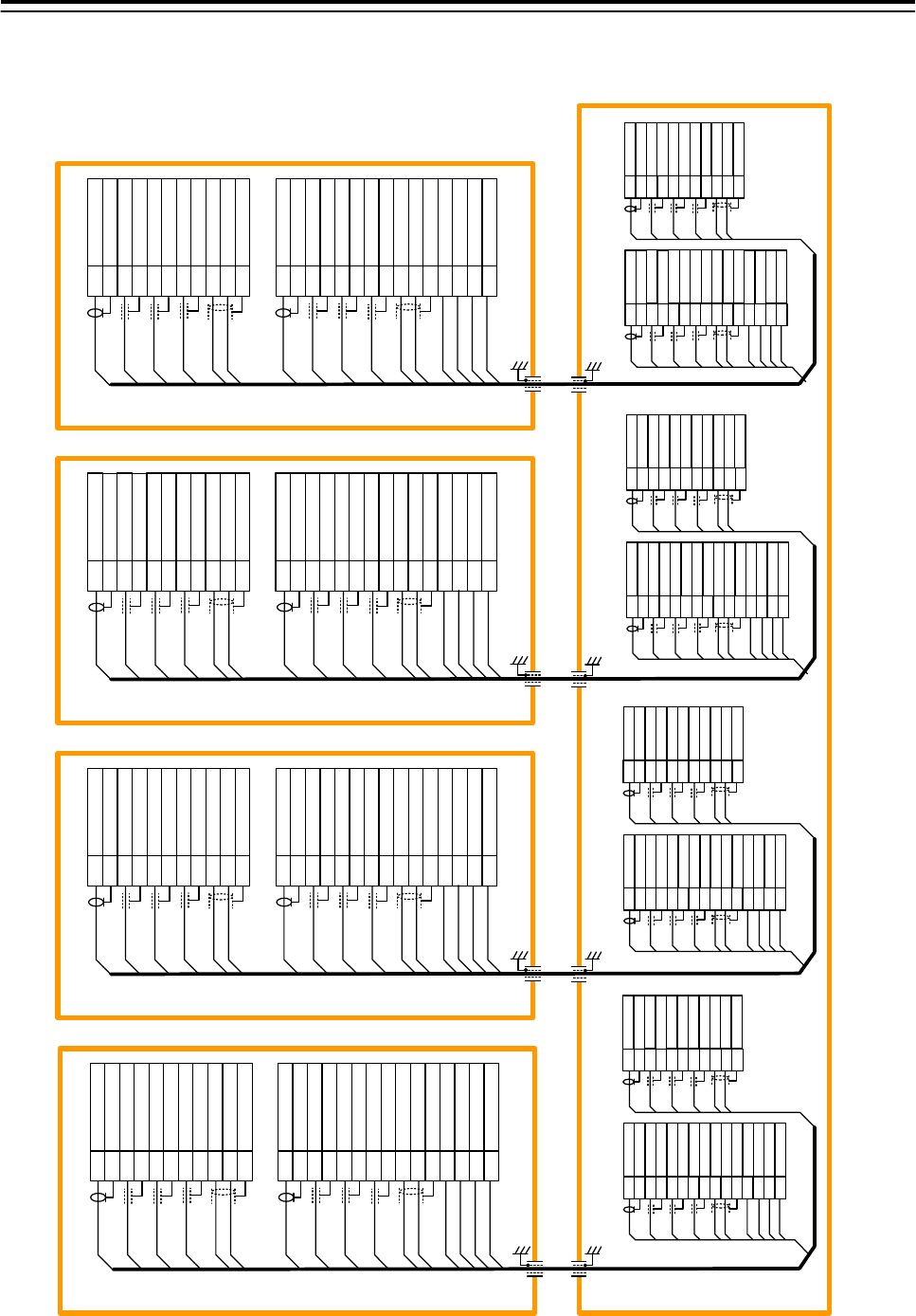
5.1.3 NQE-3141-4A Inter-board connection diagram
CH-1
TB911 TB912
No.1 RADAR
RADAR I/F Circuit CQD-2273
J833/J834
1
2
3
4
5
6
7
8
9
10
11
12
13
14
15
1
2
3
4
5
6
7
8
9
10
11
CH-2
TB913 TB914
CH-3
TB915 TB916
NQE-3141-4A
CCL-304R
ISWO_VD+
ISWO_VD-
ISWO_TRG+
ISWO_TRG-
ISWO_BP+
ISWO_BP-
ISWO_BZ+
ISWO_MTR+
ISWO_MTR-
ISWO_BZ-
ISWO_MTRG
ISWI_VD+
ISWI_VD-
ISWI_TRG+
ISWI_TRG-
ISWI_BP+
ISWI_BP-
ISWI_BZ+
ISWI_BZ-
ISWI_MTR+
ISWI_MTR-
PWROUT
PWROUTE
ISWI_MTRG
PWRIN
PWRINE
1
2
3
4
5
6
7
8
9
10
11
1
2
3
4
5
6
7
8
9
10
11
12
13
14
15
BLK1
BLK2
BLU
YEL
GRN
WHT-BLU
WHT-WHT
ORG
BLK
PNK
BRN
RED
PUR
CLR
WHT-YEL
WHT-WHT
BLK2
RED
PUR
CLR
WHT-YEL
WHT-WHT
BLK1
BLU
YEL
GRN
WHT-BLU
WHT-WHT
ORG
BLK
PNK
BRN
H-2695111153 (JRC SUPPLY)
H-2695111153 (JRC SUPPLY)
H-2695111153 (JRC SUPPLY)
CH-4
TB917 TB918
H-2695111153 (JRC SUPPLY)
J833
J834
ISWO_VD+
ISWO_VD-
ISWO_TRG+
ISWO_TRG-
ISWO_BP+
ISWO_BP-
ISWO_BZ+
ISWO_MTR+
ISWO_MTR-
ISWO_BZ-
ISWO_MTRG
ISWI_VD+
ISWI_VD-
ISWI_TRG+
ISWI_TRG-
ISWI_BP+
ISWI_BP-
ISWI_BZ+
ISWI_BZ-
ISWI_MTR+
ISWI_MTR-
PWROUT
PWROUTE
ISWI_MTRG
PWRIN
PWRINE
1
2
3
4
5
6
7
8
9
10
11
1
2
3
4
5
6
7
8
9
10
11
12
13
14
15
BLK1
BLK2
BLU
YEL
GRN
WHT-BLU
WHT-WHT
ORG
BLK
PNK
BRN
RED
PUR
CLR
WHT-YEL
WHT-WHT
J833
J834
ISWO_VD+
ISWO_VD-
ISWO_TRG+
ISWO_TRG-
ISWO_BP+
ISWO_BP-
ISWO_BZ+
ISWO_MTR+
ISWO_MTR-
ISWO_BZ-
ISWO_MTRG
ISWI_VD+
ISWI_VD-
ISWI_TRG+
ISWI_TRG-
ISWI_BP+
ISWI_BP-
ISWI_BZ+
ISWI_BZ-
ISWI_MTR+
ISWI_MTR-
PWROUT
PWROUTE
ISWI_MTRG
PWRIN
PWRINE
1
2
3
4
5
6
7
8
9
10
11
1
2
3
4
5
6
7
8
9
10
11
12
13
14
15
J833
J834
No.2 RADAR
RADAR I/F Circuit CQD-2273
J833/J834
No.1 ECDIS
RADAR I/F Circuit CQD-2273
J833/J834
No.2 ECDIS
RADAR I/F Circuit CQD-2273
J833/J834
VDIN
VDINE
TRGIN
TRGINE
BPIN
BPINE
BZIN
MTRIN+
MTRIN-
BZINE
MTRINE
PWRIN
PWRINE
PWROUT
PWROUTE
VDOUT
VDOUTE
TRGOUT
TRGOUTE
BPOUT
BPOUTE
BZOUT
MTROUT+
MTROUT-
BZOUTE
MTROUTE
1
2
3
4
5
6
7
8
9
10
11
12
13
14
15
1
2
3
4
5
6
7
8
9
10
11
BLK2
RED
PUR
CLR
WHT-YEL
WHT-WHT
BLK1
BLU
YEL
GRN
WHT-BLU
WHT-WHT
ORG
BLK
PNK
BRN
VDIN
VDINE
TRGIN
TRGINE
BPIN
BPINE
BZIN
MTRIN+
MTRIN-
BZINE
MTRINE
PWRIN
PWRINE
PWROUT
PWROUTE
1
2
3
4
5
6
7
8
9
10
11
12
13
14
15
1
2
3
4
5
6
7
8
9
10
11
BLK2
RED
PUR
CLR
WHT-YEL
WHT-WHT
BLK1
BLU
YEL
GRN
WHT-BLU
WHT-WHT
ORG
BLK
PNK
BRN
VDIN
VDINE
TRGIN
TRGINE
BPIN
BPINE
BZIN
MTRIN+
MTRIN-
BZINE
MTRINE
PWRIN
PWRINE
PWROUT
PWROUTE
1
2
3
4
5
6
7
8
9
10
11
12
13
14
15
1
2
3
4
5
6
7
8
9
10
11
BLK2
RED
PUR
CLR
WHT-YEL
WHT-WHT
BLK1
BLU
YEL
GRN
WHT-BLU
WHT-WHT
ORG
BLK
PNK
BRN
VDIN
VDINE
TRGIN
TRGINE
BPIN
BPINE
BZIN
MTRIN+
MTRIN-
BZINE
MTRINE
PWRIN
PWRINE
PWROUT
PWROUTE
BLK1
BLK2
BLU
YEL
GRN
WHT-BLU
WHT-WHT
ORG
BLK
PNK
BRN
RED
PUR
CLR
WHT-YEL
WHT-WHT
BLK1
BLK2
BLU
YEL
GRN
WHT-BLU
WHT-WHT
ORG
BLK
PNK
BRN
RED
PUR
CLR
WHT-YEL
WHT-WHT
VDOUT
VDOUTE
TRGOUT
TRGOUTE
BPOUT
BPOUTE
BZOUT
MTROUT+
MTROUT-
BZOUTE
MTROUTE
VDOUT
VDOUTE
TRGOUT
TRGOUTE
BPOUT
BPOUTE
BZOUT
MTROUT+
MTROUT-
BZOUTE
MTROUTE
VDOUT
VDOUTE
TRGOUT
TRGOUTE
BPOUT
BPOUTE
BZOUT
MTROUT+
MTROUT-
BZOUTE
MTROUTE
Fig 5-5: NQE-3141-4A Inter-board connection diagram
5.Option Unit > 5.1 Installation of Interswitch Unit
5-5
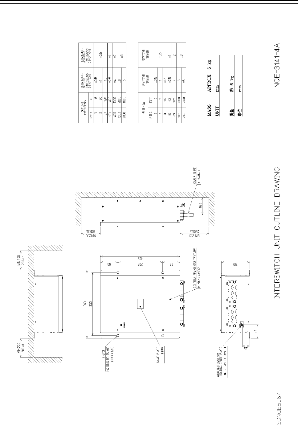
5.1.4 Installation of interswitch unit
Fig 5-6: Outline Drawing of NQE-3141-4A Interswitch Unit (4ch)
5.Option Unit > 5.1 Installation of Interswitch Unit
5-6
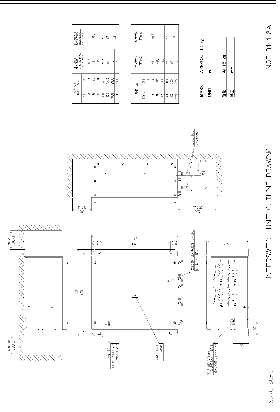
Fig 5-7: Outline Drawing of NQE-3141-8A Interswitch Unit (8ch)
5.Option Unit > 5.1 Installation of Interswitch Unit
5-7
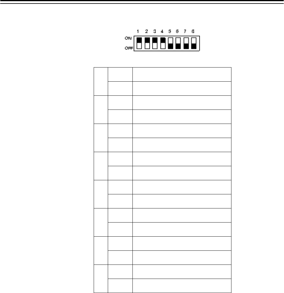
5.1.5 Settings of Interswitch
Since settings have been normally made upon shipment from factory, it is
advised to only confirm the settings.
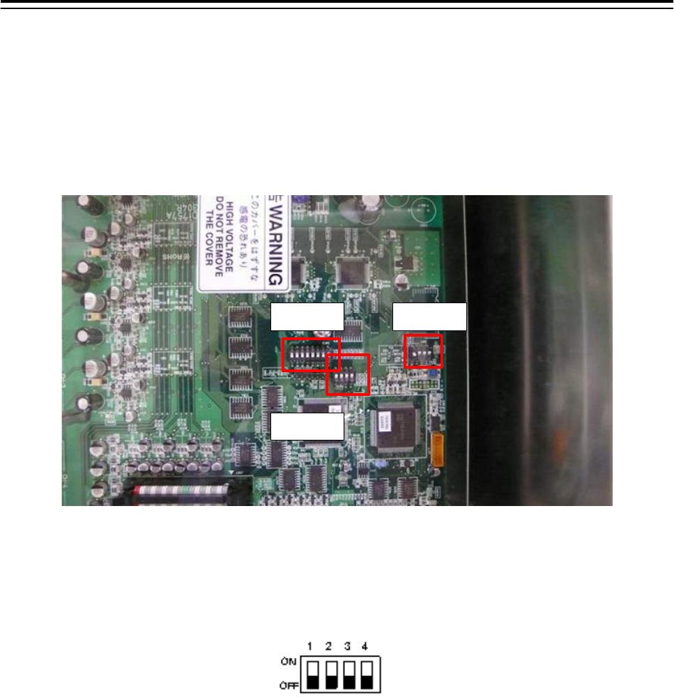
a. Settings of NQE-3141-4A
Set dip switches SW11, SW12, and SW13 as shown below.
SW11
SW13
SW12
Fig 5-8: CML-304R DIP Switch
1) SW11 setting (expansion mode, master/slave setting)
Set all OFF.
5.Option Unit > 5.1 Installation of Interswitch Unit
5-8
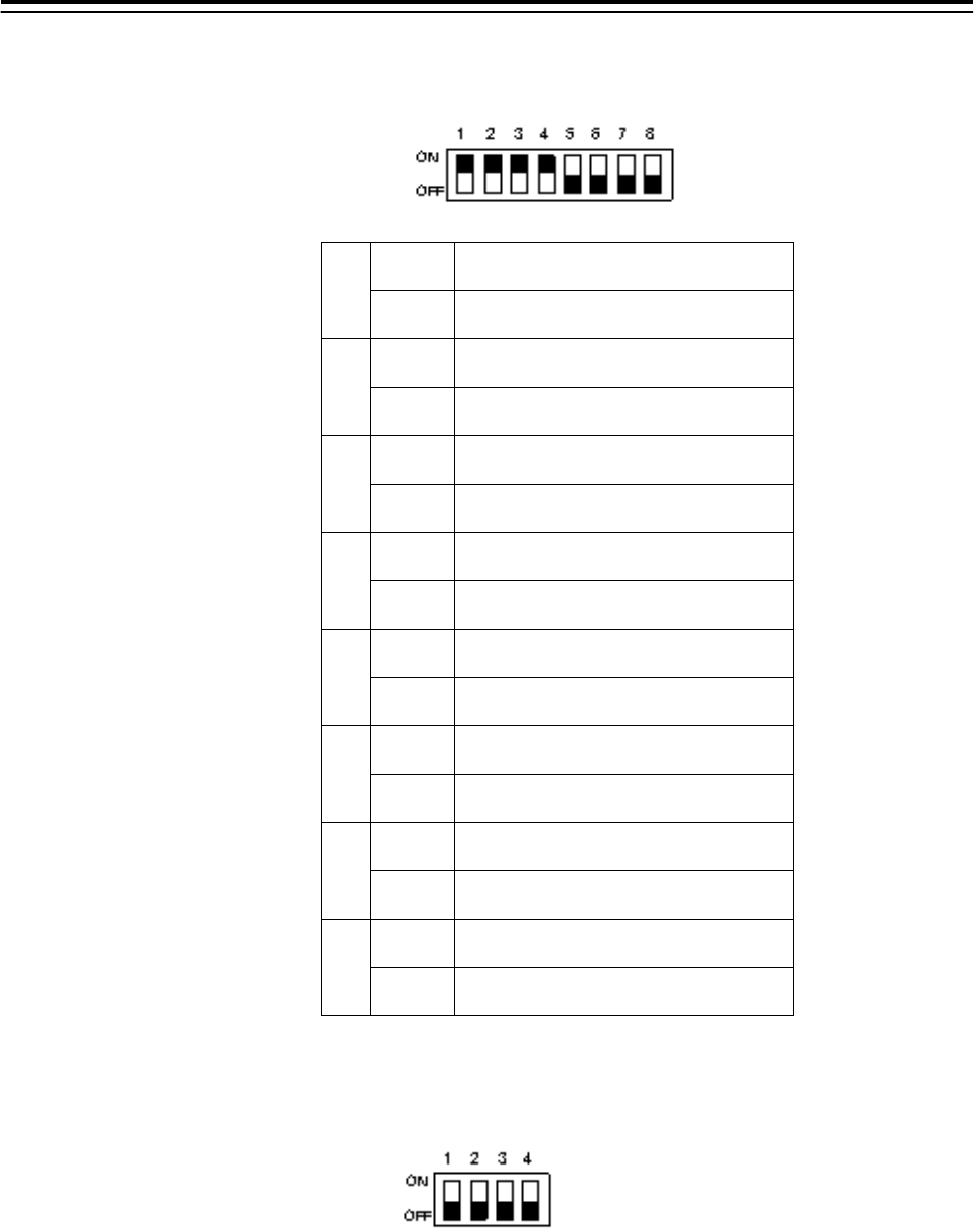
2) SW12 setting (radar connection setting)
Radar Connection Setting
1 ON
No. 1 display unit connected
OFF No. 1 display unit NOT connected
2 ON
No. 1 antenna connectedd
OFF No. 1 antenna NOT connected
3 ON
No. 2 display unit connected
OFF No. 2 display unit NOT connected
4 ON
No. 2 antenna connected
OFF No. 2 antenna NOT connected
5 ON
No. 3 display unit connected
OFF No. 3 display unit NOT connected
6 ON
No. 3 antenna connected
OFF No. 3 antenna NOT connected
7 ON
No. 4 display unit connected
OFF No. 4 display unit NOT connected
8 ON
No. 4 antenna connected
OFF No. 4 antenna NOT connected
3) SW13 (unused)
Set all OFF.
5.Option Unit > 5.1 Installation of Interswitch Unit
5-9
b. Settings of NQE-3141-8A
The internal structure of NQE-3141-8A includes two units of CCL-304R in the two-storied
structure.
Fig 5-9: NQE-3141-8A internal structure
Fig 5-10: Access to Lower Board of NQE-3141-8A

5.Option Unit > 5.1 Installation of Interswitch Unit
5-10
• Although dip switches settings are basically the same as the settings shown in Access, it is
necessary to make settings for each of the two SW12.
• It is necessary to remove six screws marked in the above drawing in order to access the first
story portion.
• With regard to SW12 board located at the upper position, make settings for CH1 to CH4.
• With regard to SW12 board located at the lower position, make settings for CH5 to CH8.
• CH1 to CH4 displayed on the terminal block mean CH5 to CH8.
• Settings have been made for SW11 and SW13 upon shipment. Do not change those
settings.
Factory default setting (bit1-bit2-bit3-bit4)
SW11-upper OFF-OFF-OFF-ON
SW11-lower OFF-OFF-ON-ON
SW13-both OFF-OFF-OFF-OFF

5.Option Unit > 5.1 Installation of Interswitch Unit
5-11
• Settings of upper CCL-304R, SW12 (radar connection setting)
1 ON
No. 1 display unit connected
OFF No. 1 display unit NOT connected
2 ON
No. 1 antenna connected
OFF No. 1 antenna NOT connected
3 ON
No. 2 display unit connected
OFF No. 2 display unit NOT connected
4 ON
No. 2 antenna connected
OFF No. 2 antenna NOT connected
5 ON
No. 3 display unit connected
OFF No. 3 display unit NOT connected
6 ON
No. 3 antenna connected
OFF No. 3 antenna NOT connected
7 ON
No. 4 display unit connected
OFF No. 4 display unit NOT connected
8 ON
No. 4 antenna connected
OFF No. 4 antenna NOT connected
5.Option Unit > 5.1 Installation of Interswitch Unit
5-12
• Setting of lower CCL-304R, SW12 (radar connection setting)
1 ON
No. 5 display unit connected
OFF No. 5 display unit NOT connected
2 ON
No. 5 antenna connected
OFF No. 5 antenna NOT connected
3 ON
No. 6 display unit connected
OFF No. 6 display unit NOT connected
4 ON
No. 6 antenna connected
OFF No. 6 antenna NOT connected
5 ON
No. 7 display unit connected
OFF No. 7 display unit NOT connected
6 ON
No. 7 antenna connected
OFF No. 7antenna NOT connected
7 ON
No. 8 display unit connected
OFF No. 8 display unit NOT connected
8 ON
No. 8 antenna connected
OFF No. 8 antenna NOT connected
5.1.6 Confirmation after installation
1) After having checked connections, turn on the switchboard breaker.
2) Turn on the power to the radar display unit, and make sure that the interswitch button is
displayed on the screen and pressing the button will switch antennas.
3) When a system consists of two devices, make sure that both left and right radars conform to
the screen indication.
4) When a system consists of three devices, make sure that the CH number and the display
unit position are arranged as intended.

5.Option Unit > 5.2 Installation of Power Control Unit
5-13
5.2 Installation of Power Control Unit
Power control unit NQE-3167 is used when an antenna and a transmitter-receiver are installed at
a location away from the bridge, such as a foremast.
In the case of a two-unit type antenna, the maximum length of the cable that connects between
the display unit and the antenna is 65 meters. In the case of a three-unit type antenna, the
maximum length of the cable that connects between the display unit and the transmitter-receiver
is 35 meters.
By using NQE-3167 power control unit, the maximum length of the cable that connects between
the display unit and the antenna (transmitter-receiver) can be extended up to 465 meters.
Maximum length of the cable connecting between the
antenna and the transmitter-receiver
30m
Maximum length of the cable connecting between the
transmitter-receiver and the PCU (NQE-3167)
35m
Maximum length of the cable connecting between the
display unit and the PCU (NQE-3167)
400m
5.2.1 Connection with NKE-2103 type and NKE-2254-6HS type scanner units
Use 19-core composite cable CFQ-6912-** for the installation of those types of antennas
(Asterisks ** use the cable length, and the available cable length is 5, 10, 20, 30, 40, 50, and 65)
The display-unit side end of this cable is a metal shell round connector. (See 2.1.1CFQ-6912-** )
Connect that cable to J2 of the power control unit.
If the metal shell round connector is cut, connect the cable to TB3 located in the power control
unit. For procedures for processing the cable end, see Section 2.1.4 Cable end processing
method.
With regard to six devices, such as MOTOR+ (2P), MOTOR-(2P), 1A (+48V), and 2A (48VG),
two AWG16 cables must be connected to one terminal block. As necessary, use a bar-mould
crimp-type terminal or the like. (See Fig 5-11: Connection of CFQ-6912)
The connection between scanner unit and AC/DC converter NBA-5135 is not necessary.
Instead, power control unit NQE-3167 supplies DC power.
5.Option Unit > 5.2 Installation of Power Control Unit
5-14
Fig 5-11: Connection of CFQ-6912
5.Option Unit > 5.2 Installation of Power Control Unit
5-15
5.2.2 Connections to NKE-1125, NTG-3225, NKE-1130, NTG-3230, NKE-1632 and NKE-2632
Use 14-core composite cable 2695110056 for the installation of those types of antennas.
For the procedures for processing the cable end, see Fig 5-12: Equipment cable end processing.
For the wiring procedures, see 5.2.7 Inter –board connection diagram of power control unit.
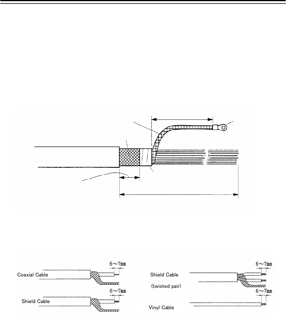
5.2.3 End processing of 2695110056 cable
abt. 80 mm terminal
Inner Shield
Outer Shield
taping
1000 mm
Width for
clamping cable.
30 mm
2695110056
2695111153
abt.
abt.
Fig 5-12: Equipment cable end processing
5.2.4 End processing of each cable core
Fig 5-13: End processing of each cable core
5.2.5 Connection to display unit
Use 14-core composite cable 2695110056 and coaxial cable RG-10/UY to connect power control
unit NQE-3167 to each display unit.
Among the two cables, use coaxial cable RG-10/UY to connect the radar video signal.
For the procedures for processing the cable end and the wiring procedures, see Fig 5-12:
Equipment cable end processing. For the wiring procedures, see 5.2.7 Inter –board connection
diagram of power control unit.
5.Option Unit > 5.2 Installation of Power Control Unit
5-16
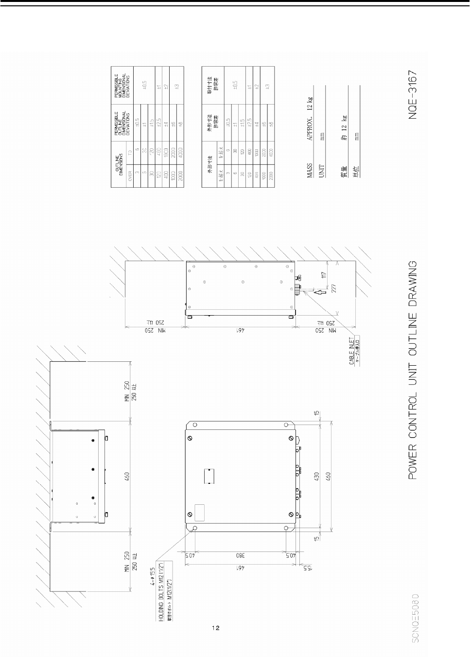
5.2.6 Outline Drawing of NQE-3167 Power Control Unit
Fig 5-14: Outline Drawing of NQE-3167 Power Control Unit
5.Option Unit > 5.2 Installation of Power Control Unit
5-17
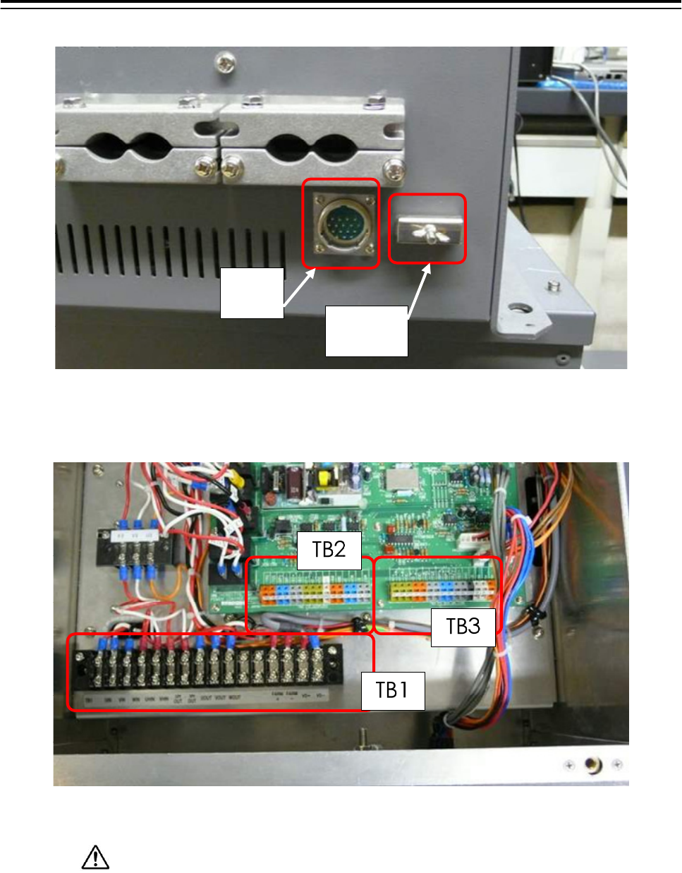
J2
EARTH
PLATE
Fig 5-15: NQE-3167 cable entrance
Fig 5-16: NQE-3167 terminal block
Securely ground the included earth plate to the hull's earth.
5.Option Unit > 5.2 Installation of Power Control Unit
5-18
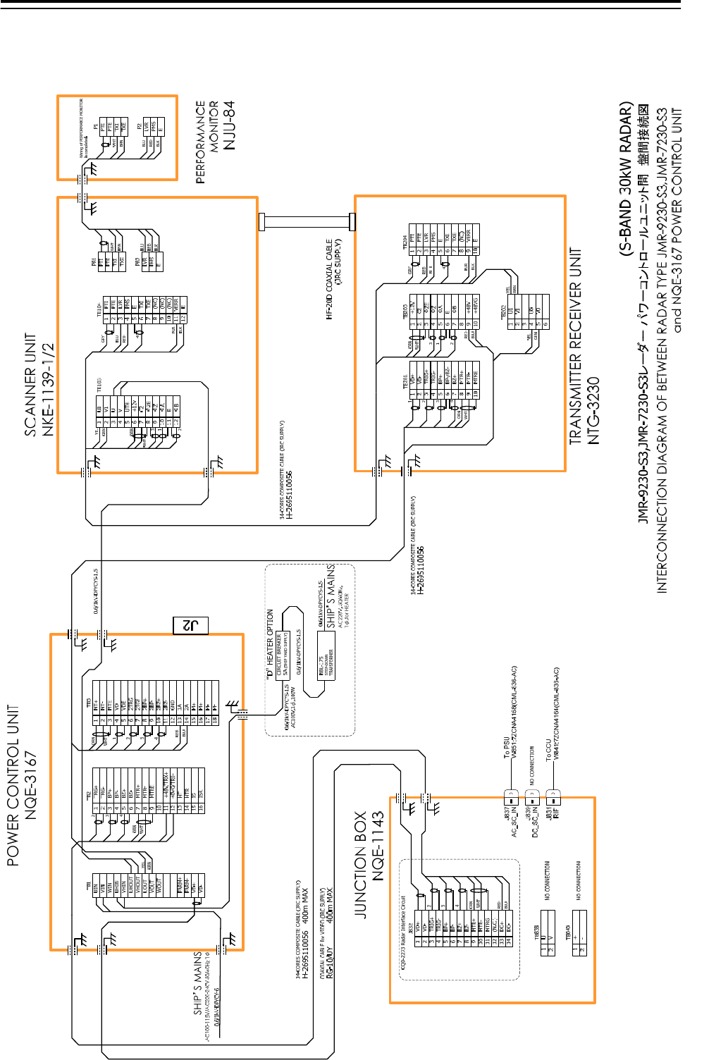
5.2.7 Inter –board connection diagram of power control unit
5.2.7.1 Inter-board connection diagram of JMR-9230-S3, JMR-7230-S3
5.Option Unit > 5.2 Installation of Power Control Unit
5-19
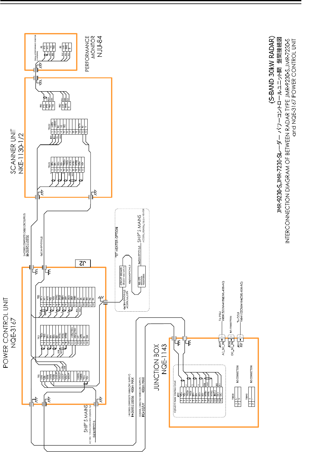
5.2.7.2 Inter-board connection diagram of JMR-9230-S, JMR-7230-S
5.Option Unit > 5.2 Installation of Power Control Unit
5-20
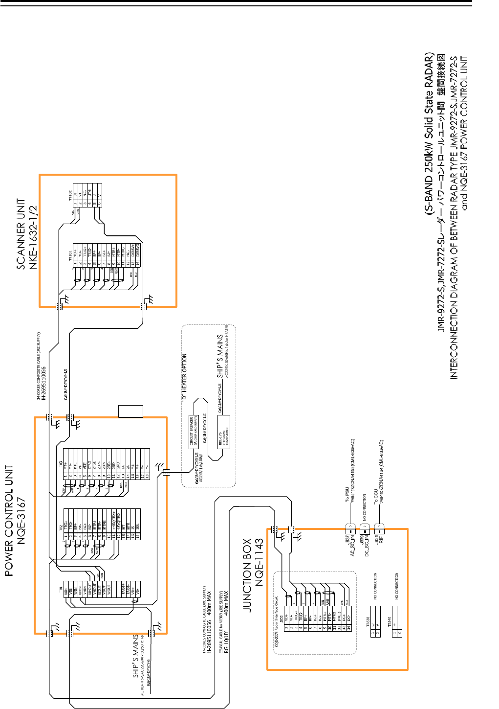
5.2.7.3 Inter-board connection diagram of JMR-9272-S, JMR-7272-S
J2
5.Option Unit > 5.2 Installation of Power Control Unit
5-21
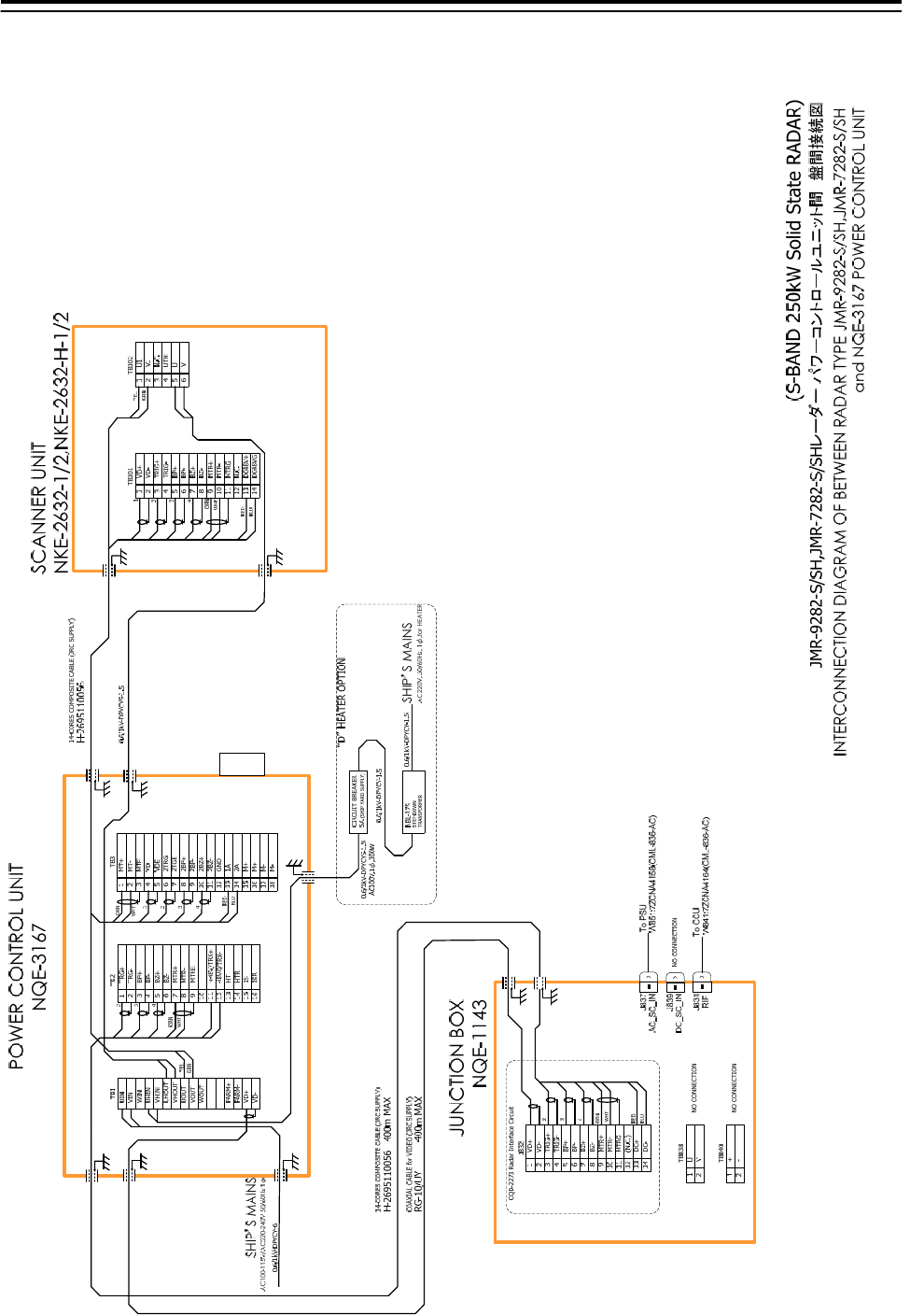
5.2.7.4 Inter-board connection diagram of JMR-9282-S/SH, JMR-7282-S/SH
J2
5.Option Unit > 5.2 Installation of Power Control Unit
5-22
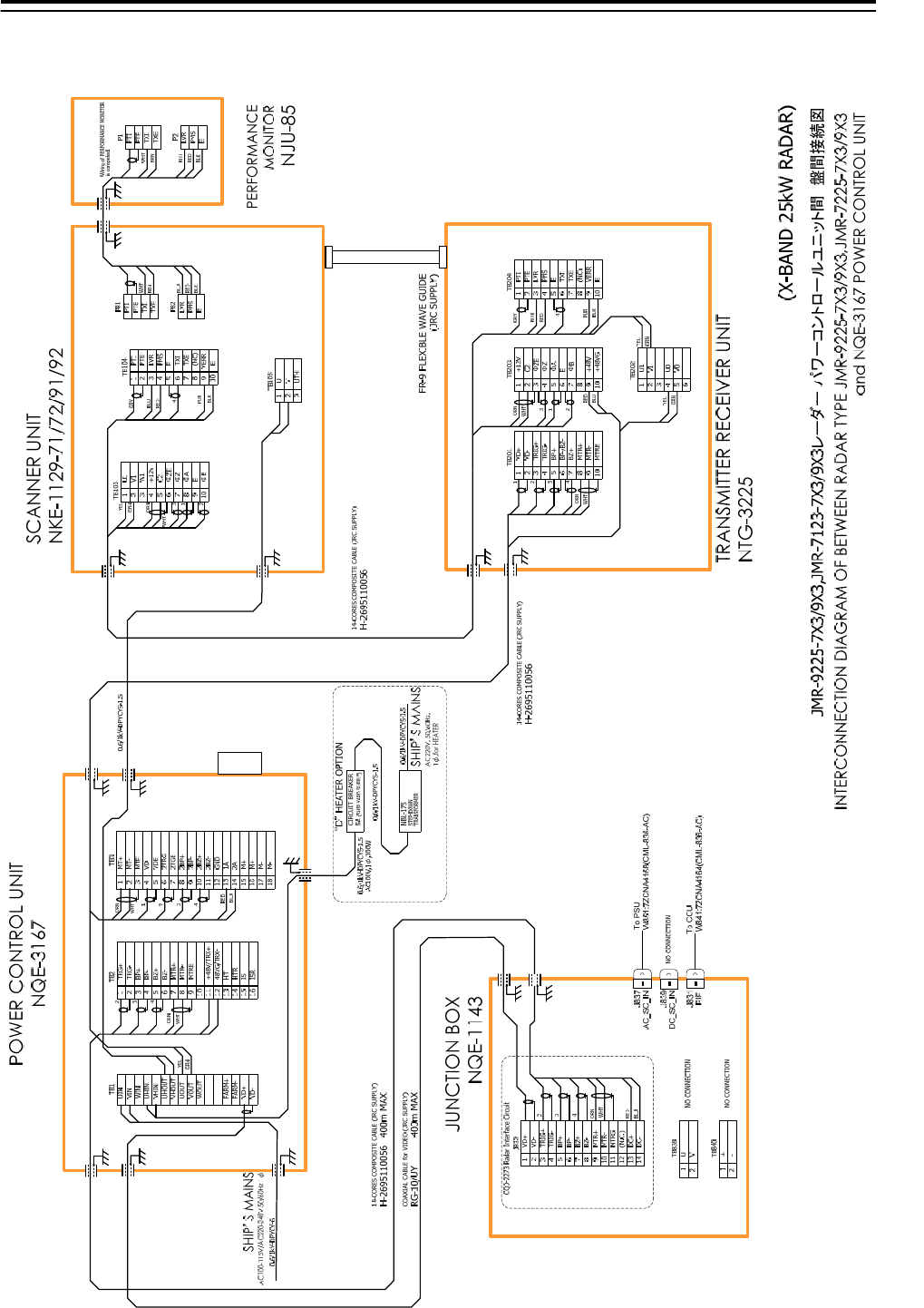
5.2.7.5 Inter-board connection diagram of JMR-9225-7X3/9X3, JMR-7225-7X3/9X3
J2
5.Option Unit > 5.2 Installation of Power Control Unit
5-23
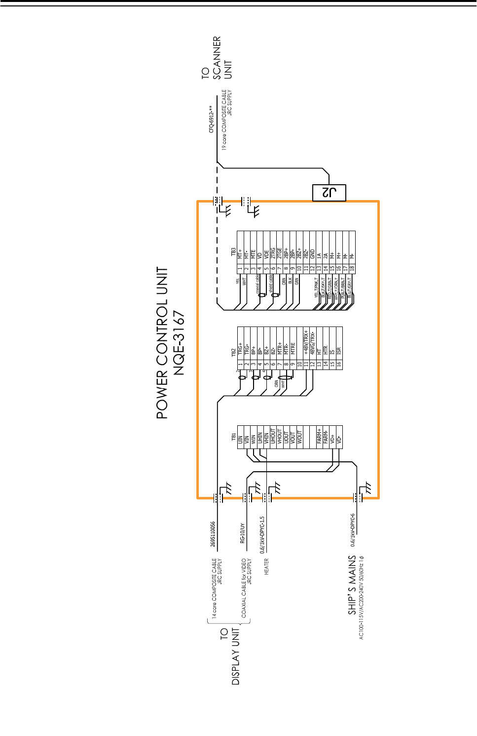
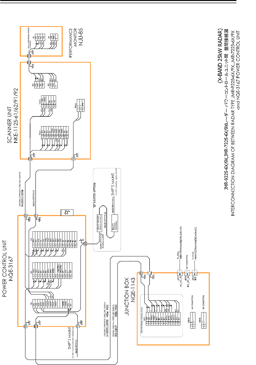
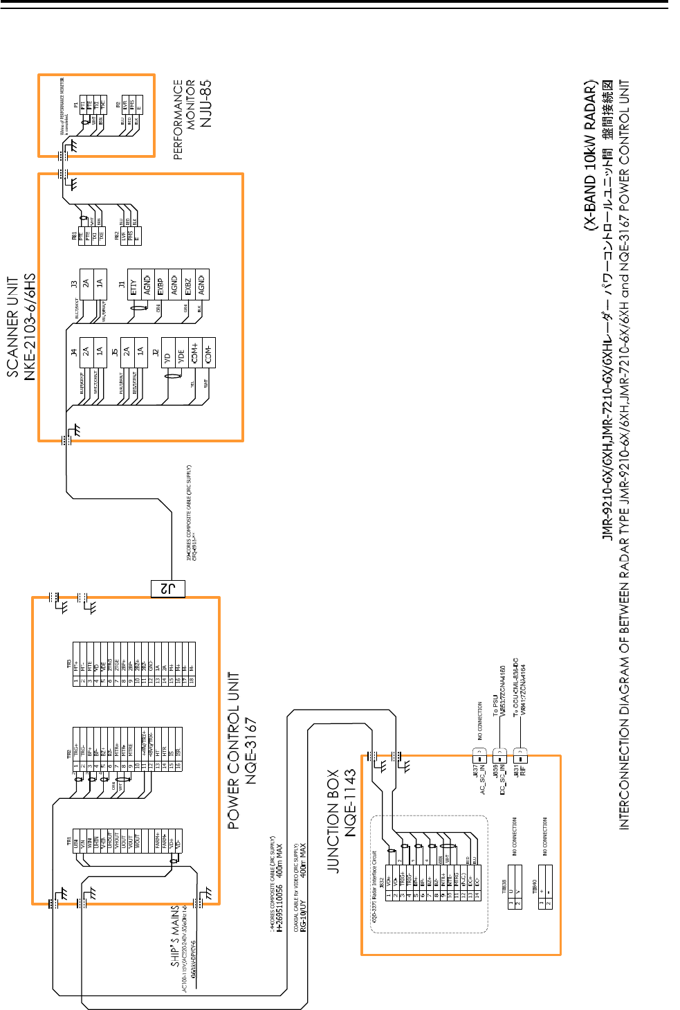
5.2.7.6 Inter-board connection diagram of JMR-9225-6X/9X, JMR-7225-6X/9X
5.Option Unit > 5.2 Installation of Power Control Unit
5-24
5.2.7.7 Inter-board connection diagram of JMR-9225-6XH, JMR-7225-6XH
(X-BAND 25kW RADAR)
JMR-9225-6XH,JMR-7225-6XHレーダー パワーコントロールユニット間 盤間接続図
19-CORES COMPOSITE CABLE (JRC SUPPLY)
CFQ-6912-**
21
MTRE
2
3
BZ+
4
BZ-
5
TRG+
6
TRG-
7
BP+
8
BP-
9
10
MTR+
MTR-
TB2
3
4
ORN
WHT
48VG/TRX-
11
12
+48V/TRX+
HTR
13
14
HT
ISR
15
16
IS
VHIN
UHOUT
UIN
VIN
WIN
UHIN
VHOUT
UOUT
VOUT
WOUT
FARM+
FARM-
VD+
VD-
TB1 TB3
POWER CONTROL UNIT
NQE-3167
SHIP’S MAINS
AC100-115V/AC220-240V 50/60Hz 1φ
0.6/1kV-DPYCY-6
COAXIAL CABLE for VIDEO (JRC SUPPLY)
RG-10/UY 400m MAX
14-CORES COMPOSITE CABLE (JRC SUPPLY)
H-2695110056 400m MAX
2A
1A
J4
J5
J2
2A
1A
VD
VDE
2A
1A
J3
J1
PTI
PTE
TXI
TXE
LVR
PMS
E
P82
P81
PTI
PTE
TXI
TXE
LVR
PMS
E
P2
P1
SCANNER UNIT
NKE-2254-6HS
PERFORMANCE
MONITOR
NJU-85
WHT
BRN
BLU
RED
BLK
WHT
BRN
BLU
RED
BLK
BLK.T/SKY.T
YEL.T/PNK.T
ORN
GRN
BLK
WHT
YEL
PUR.T/BRN.T
RED.T/GRN.T
WHT.T/ORN.T
BLU.T/GRY.T
1
2
3
U
V
UTH
TB105
CIRCUIT BREAKER
5A (SHIP YARD SUPPLY)
0.6/1kV-DPYCYS-1.5
AC100V,1φ,100W
NBL-175
STEP-DOWN
TRANSFORMER
0.6/1kV-DPYCYS-1.5
0.6/1kV-DPYCYS-1.5 SHIP’S MAINS
AC220V, 50/60Hz, 1φ,for HEATER
“D”HEATER OPTION
Wiring of PERFORMANCE MONITOR
is completed.
0.6/1kV-DPYCYS-1.5
INTERCONNECTION DIAGRAM OF BETWEEN RADAR TYPE JMR-9225-6XH/JMR-7225-6XH
and NQE-3167 POWER CONTROL UNIT
1
2BP-
2
3
VDE
4
2TRG
5
MT+
6
MT-
7
MTE
8
VD
9
10
2TGE
2BP+
GND
11
12
2BZ-
2A
13
14
1A
M+
15
16
M+
2BZ+
M-
17
18
M-
MTR+
MTR-
TIY
TIYE
BP
BPE
BZ
BZE
1VD+
2VD-
3TRIG+
4TRIG-
5BP+
6BP-
7BZ+
8BZ-
9MTR+
10 MTR-
11 MTRG
12 (N.C.)
13 DC+
14 DC-
J832
JUNCTION BOX
NQE-1143
CQD-2273 Radar Interface Circuit
NO CONNECTION
RED
BLU
3
ORN
WHT
2
4
TB838
2 V
1 U
NO CONNECTION
TB840
2 -
1 +
J837
J839
J831
RIF
DC_SC_IN
AC_SC_IN
To PSU
W853:7ZCNA4160
To CCU CML-836-DC
W841:7ZCNA4164
NO CONNECTION
5.Option Unit > 5.2 Installation of Power Control Unit
5-25
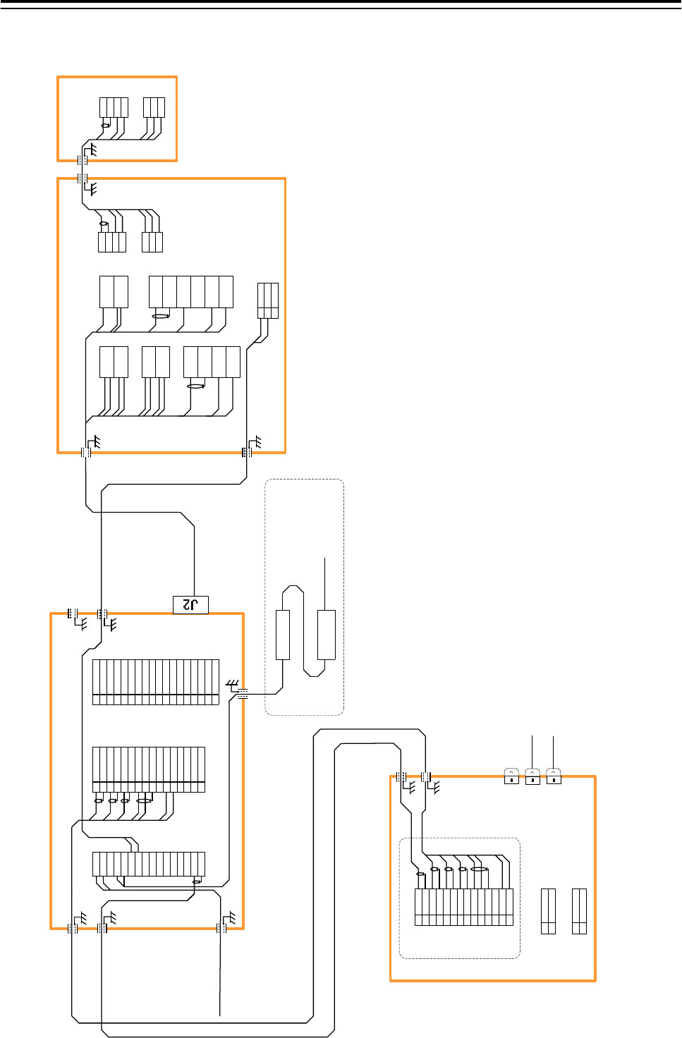
5.2.7.8 Inter-board connection diagram of JMR-9210-6X/6XH, JMR-7210-6X/6XH
5.Option Unit> 5.3 Connection of VDR
5-26
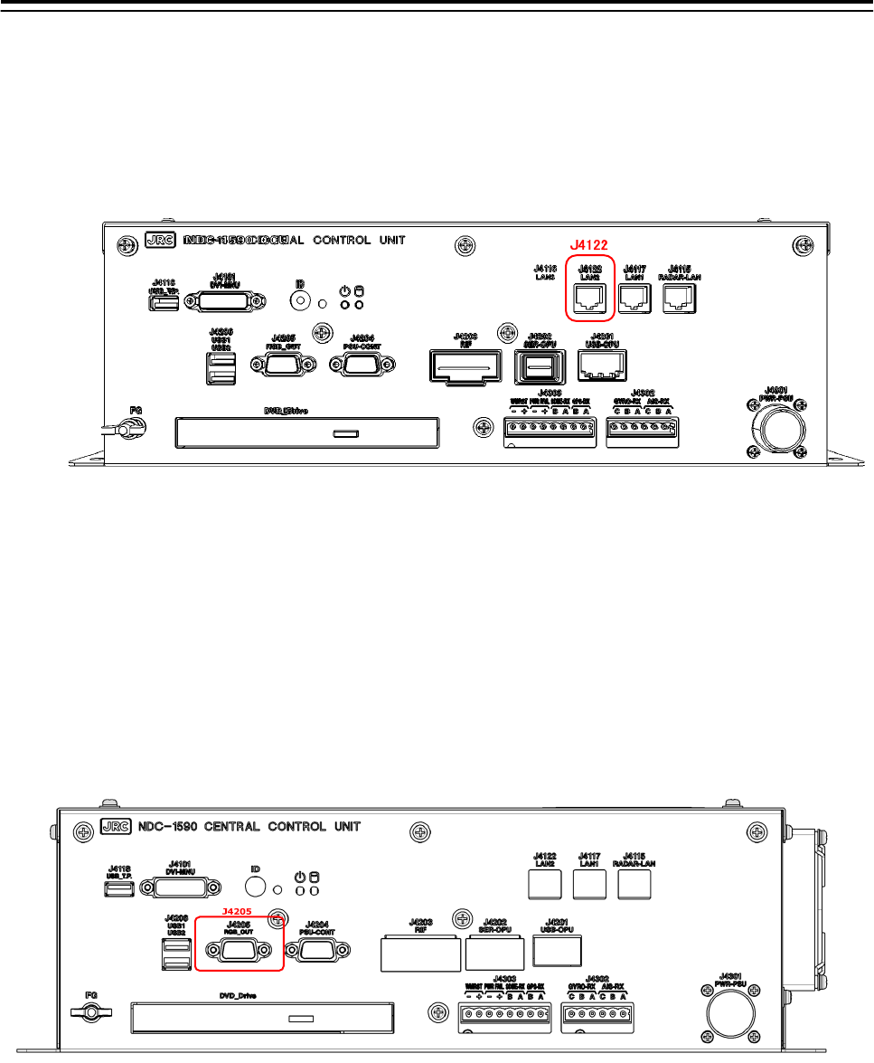
5.3 Connection of VDR
5.3.1 Connection with LAN (IEC61162-450)
When the VDR have LAN port, use connection with the LAN (IEC61162-450). There is the
LAN port J4122 which is located in central control unit (NDC-1590). See the drawing below.
Fig 5-17 VDR connection connector LAN(IEC61162-450)
After the connection, please set the display unit refers to the 4.15 Setting of VDR.
5.3.2 Connection with Analog RGB
When the VDR does not have LAN port, use connection with Analog RGB.
Analog RGB signal for VDR is output from J4205 which is located in the central
control unit (NDC-1590). See the drawing below.
Fig 5-18: VDR connection connector Analog RGB
5.Option Unit> 5.4 Printer
5-27
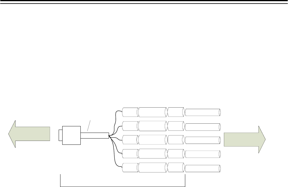
5.3.2.1 VDR I/F kit
The VDR I/F kit is used to connection with analog RGB.
VDR I/F kit CQD-1891 includes:
DSUB15P - BNC cable (KB5BNC2K, 2 meters) 1 pcs
BNC to BNC adapter (BNC-A-JJ) 5 pcs
BNC connector (3CV-P2) 5 piece 5 pcs
Use 3C-2V coaxial cable for connection.
RED
GRN
BLU
GRY
BLK
RED :red
GRN :green
BLU :blue
GRY :HSYNC
BLK :VSYNC
KB-5BNC2K
BNC BNC-A-JJ
BNC
BNC
BNC
BNC
BNC-A-JJ
BNC-A-JJ
BNC-A-JJ
BNC-A-JJ
3C-2V
3C-2V
3C-2V
3C-2V
3C-2V
3CV-P2
3CV-P2
3CV-P2
3CV-P2
3CV-P2
CQD-1891
TO VDR
NDC-1590
J4205
Fig 5-19: CQD-1891 VDR I/F Kit
5.Option Unit> 5.4 Printer
5-28
5.4 Printer
Set the printer accoding to the following procedures.
When there is no keyboard operating unit, prepare the keyboard of a
USB interface.
There is a procedure that cannot be set for the keyboard not to exist.
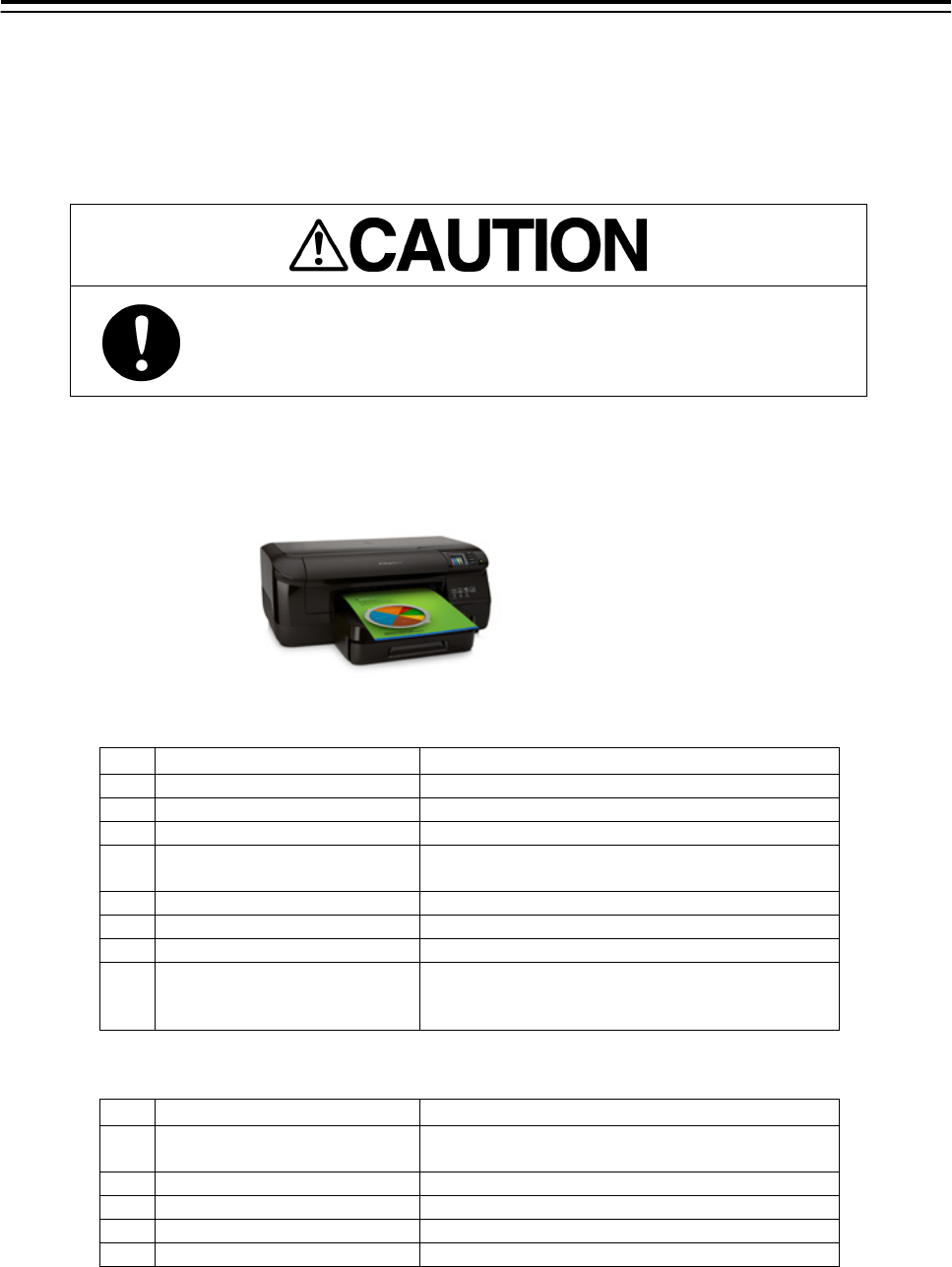
5.4.1 Printer Composition
Externals of the printer are as follows.
●Necessary for setting
No 名称 備考
1 Start Poster
2 AC Adaptor
3 CD for Printer Driver
4 Two sided of automatic op-
eration print accessories
5 Ink
6 Printer Head
7 Print Paper
8 USB Keyboard
When NCE-5625 Keyboard Operation Unit is
not equipped.
●Not necessary for setting
No 名称 備考
LAN Cable It doesn't use.
Use the specified LAN cable.
USB Cable It doesn't use.
Warranty Card Please keep it with the ship importantly.
Directions of print paper Please keep it with the ship importantly.
Support documentation Please keep it with the ship importantly.
5.Option Unit> 5.4 Printer
5-29
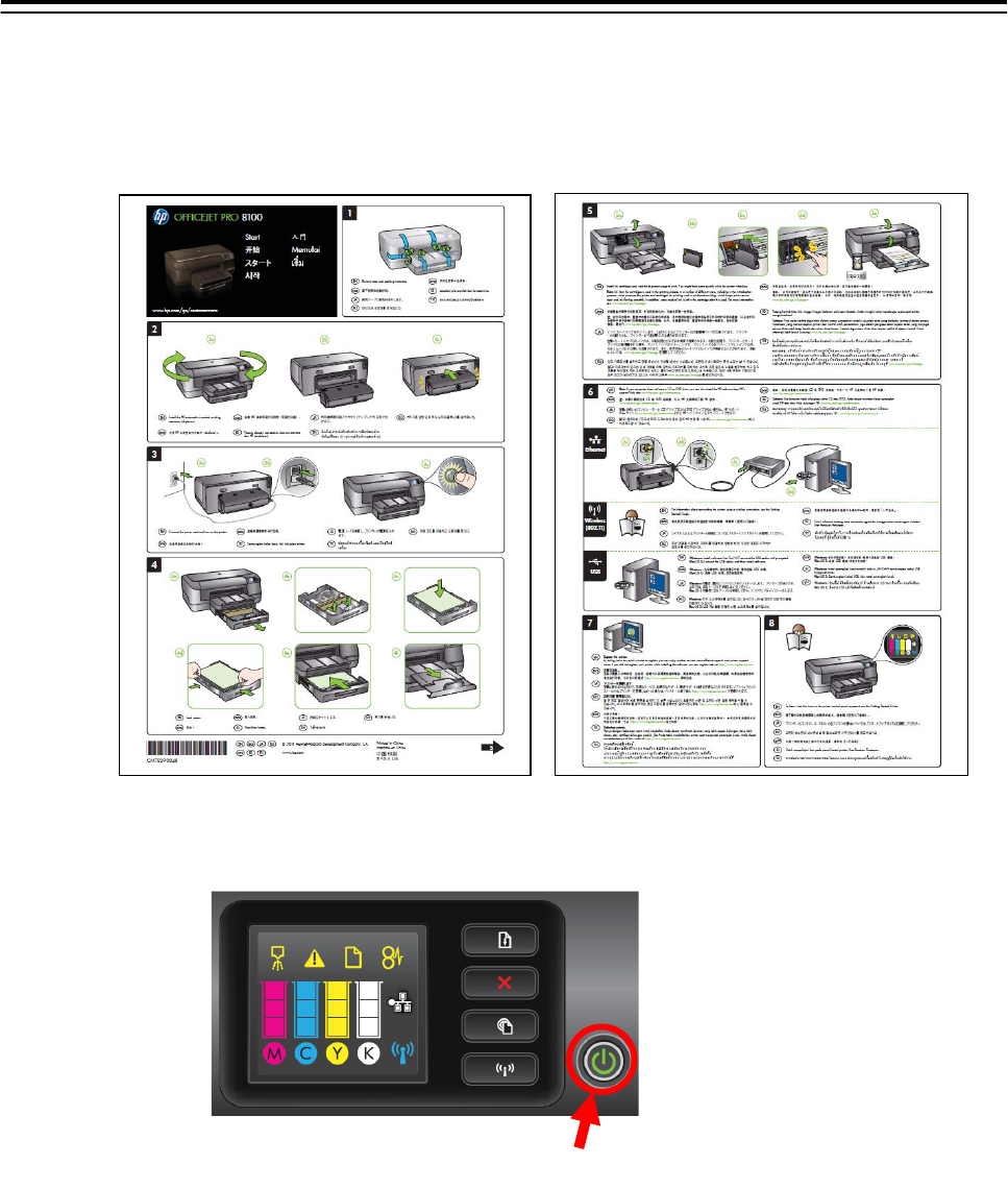
5.4.2 Printer Assembly
Assemble a printer according to the following procedures.
① Set up the printer according to attached “Start” poster.
② Set some papers and push the power button.
Power button
5.Option Unit> 5.4 Printer
5-30
5.4.3 Setting Printer
The setting method of the printer is described.
Set the printer according to the following procedures.
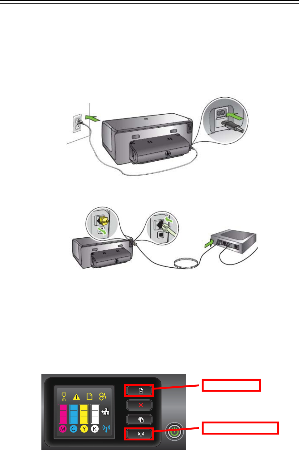
5.4.3.1 Connecting Power Cable and Printer LAN Cable
Connect power cable and printer LAN cable with the printer and main hub unit respectively. Con-
necting location is described to “Start” poster.
Connecting location of power cable
Connecting location of LAN cable
5.4.3.2 Confirming Printer IP Address
Confirm IP address of the printer according to the following procedures.
1. Power on Printer and ECDIS.
2. Keep pressing “Resume” button and “Wireless” button (see below diagram) at the same
time.
Confirm that 2 pieces of paper ” HP Network Configuration Page” are printed.
“Resume” but-
“Wireless” button
5.Option Unit> 5.4 Printer
5-31
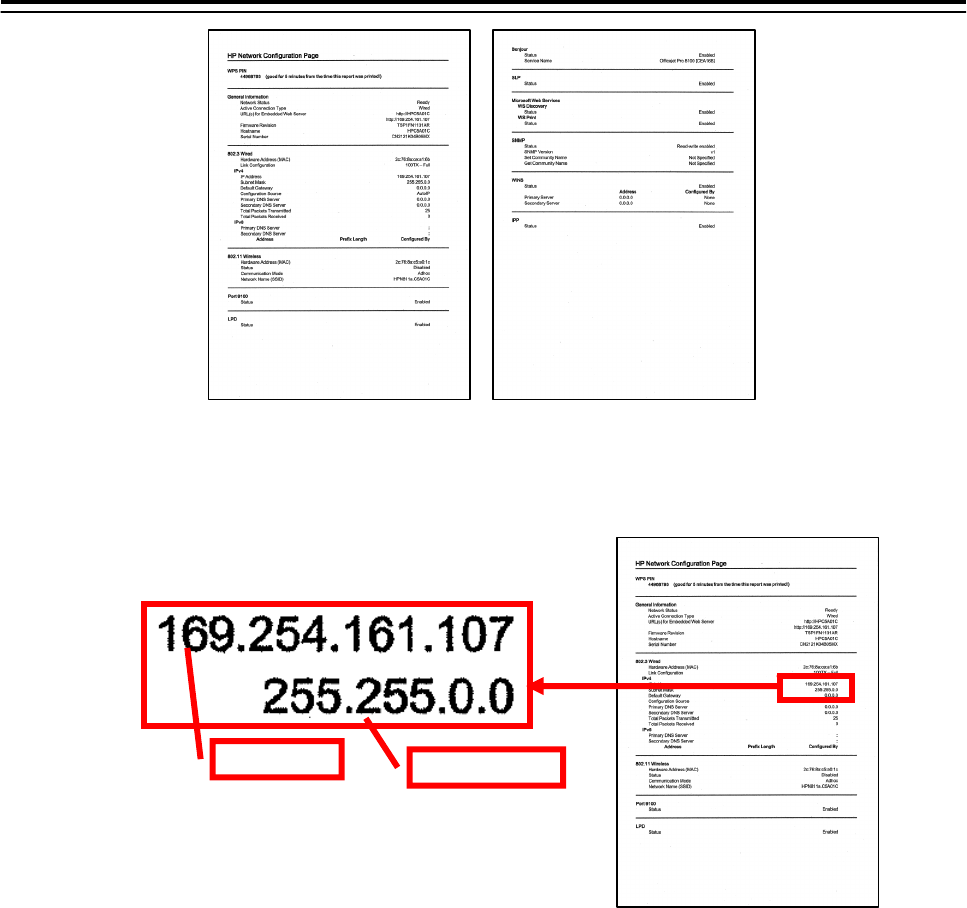
3. Confirm default ”IP Address” and ”Subnet Mask” on the “HP Network Configuration
Page”.
5.4.3.3 Setting Printer IP Address
Set up the IP address of the printer according to the following procedures.
1. Power on this equipment.
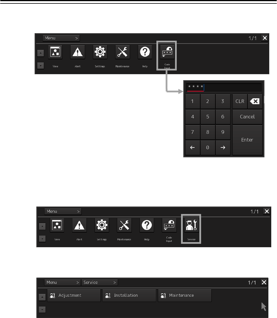
2. After the default task starts, click the [Menu] button of the “Left Tool Bar”.
The “Menu” dialog is displayed.
Default ”IP Address” and ”Subnet Mask”
IP Address Subnet Mask
ex)
5.Option Unit> 5.4 Printer
5-32
3. Click [Code Input] button.
The “Password” dialog is displayed.
4. After the password "0009" is input with the software keyboard, click the [Enter] button.
The [service] button is added to the menu. Once the [Service] button is added, it will be dis-
played until the task menu is finished.
5. Click the [Service] button of the “Menu” dialog.
The sub menu of [Service] is displayed.
6. Click the [Installation] button.
The “Installation” dialog is displayed.
5.Option Unit> 5.4 Printer
5-33
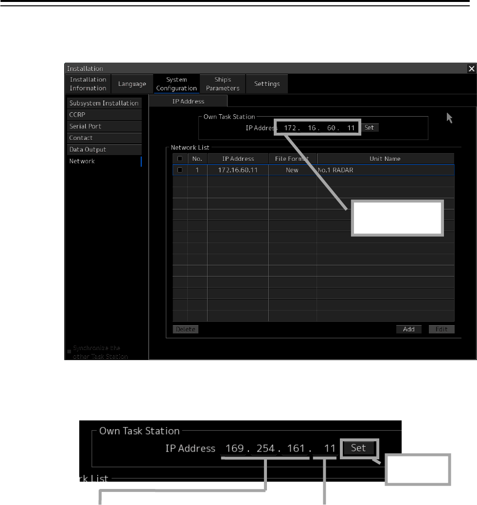
7. [System Configuration] is chosen by the first classification pane, and [Network] is chosen
by the second classification pane.
The “Network” dialog is displayed on the edit pane. Make a note of the present IP address.
8. According to the following explanation, input the IP address of "Own Task Station" and
click the [Set] button.
9. Click the [Code Input] button of the “Menu” dialog. And after the password "9999" is
input with the software keyboard, click the [Enter] button.
The task is finished and it returns to the task menu screen.
1st to 3rd octet
Input the default IP address of the
printer.
4th octet
Input a different value from the default IP
address of the printer.
Click after
input
Make a note of
the IP address.
5.Option Unit> 5.4 Printer
5-34
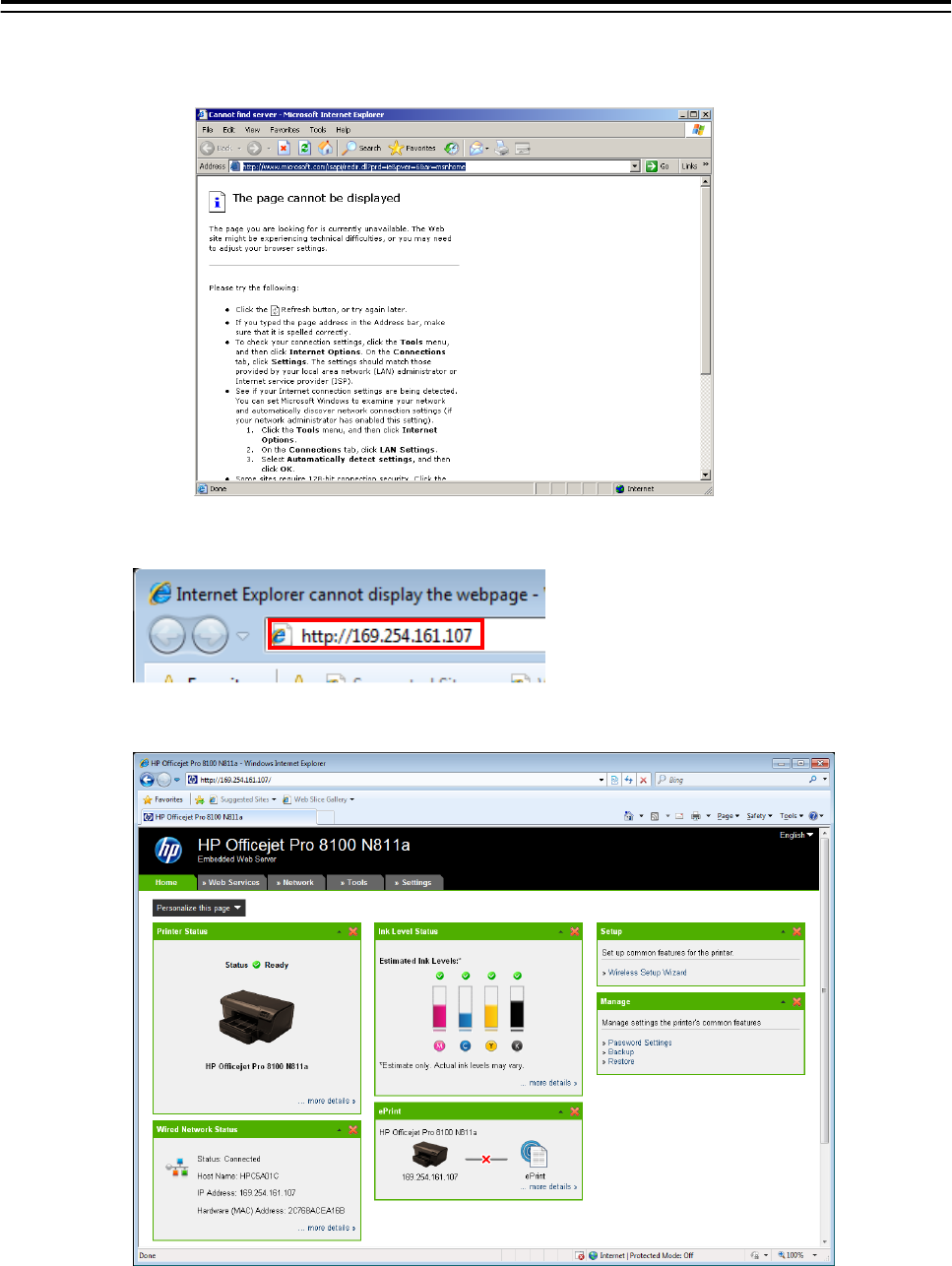
10. Input the password "0913" into the “Code input” box of the task menu screen.
The “Internet Explore” is displayed.
11. Input [http://IP address of printer] into the address bar.
“HP Officejet Pro 8100 N811a” page is displayed.
5.Option Unit> 5.4 Printer
5-35
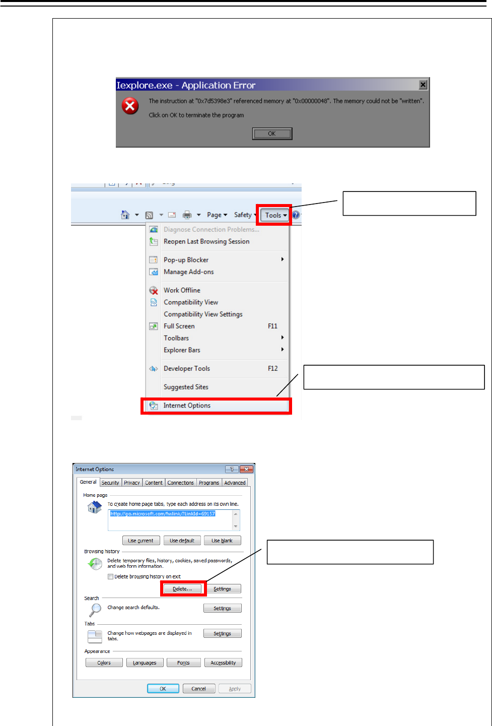
Note:
When following error is displayed, delete “Temporary Internet files” as follows.
1) Start Internet explorer again. Select "Tools" - “Internet Options…"
2) “Internet Options" dialog is displayed. Click [Delete...] button.
Click [Delete...] button
1) Select "Tools".
2) Select “Internet Options…".
5.Option Unit> 5.4 Printer
5-36
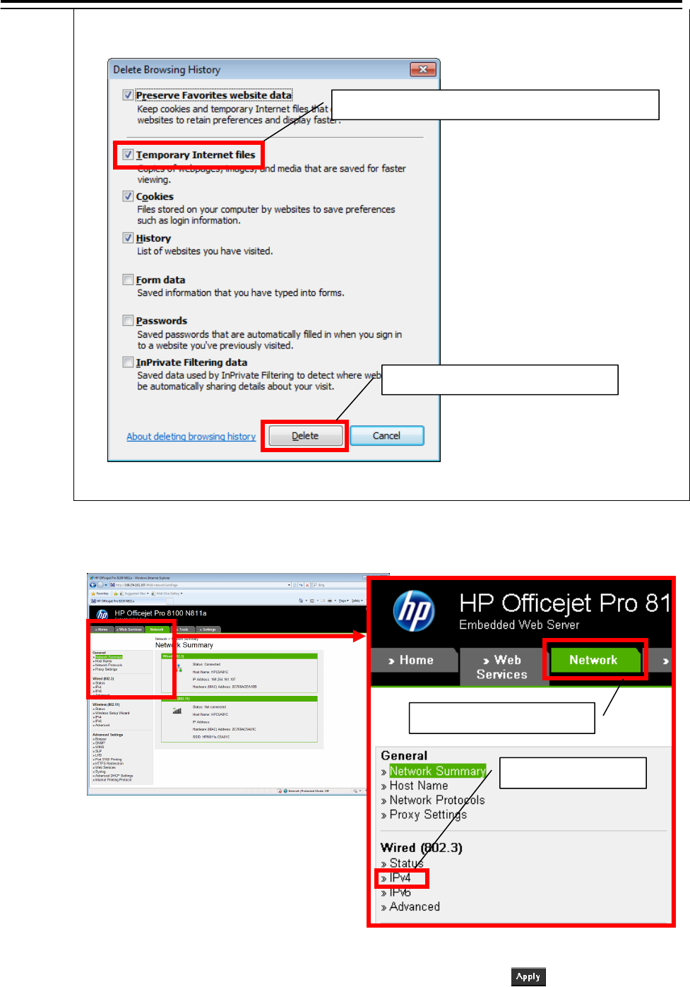
3) “Delete Browsing History” dialog is displayed. Check “Temporary Internet Files” and
click [Delete] button.
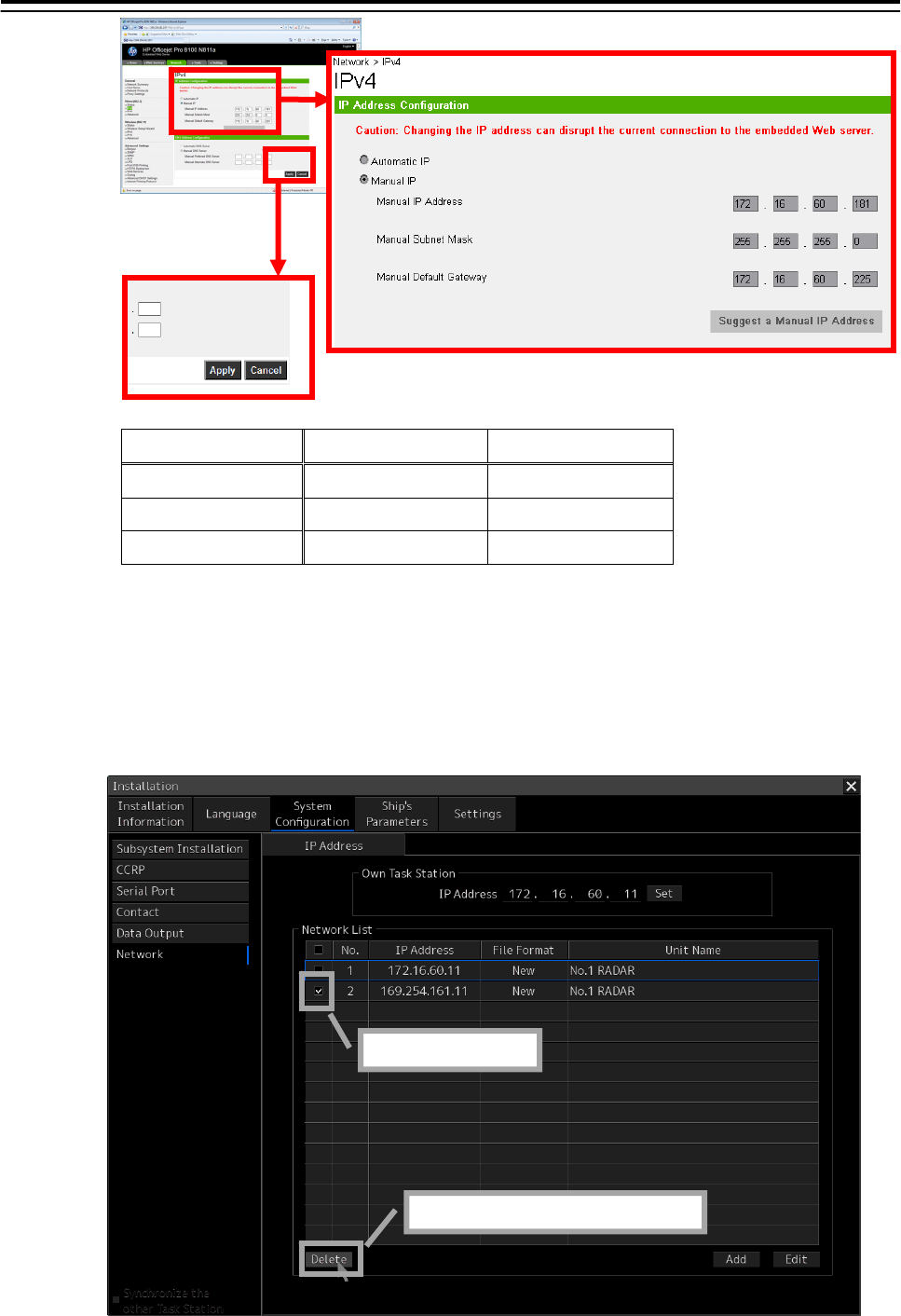
12. Click [Network] and select ”IPv4”of ”Wired (802.3)”.
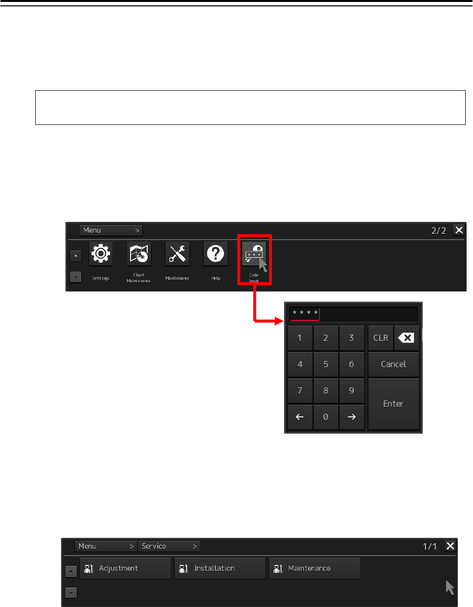
13. Enter “Manual IP Address”, ”Manual Subnet Mask” and “Manual Default Gate-
way” according to bellow diagram. After enter the value, click button.
1) Click ”Network” tab
2) Select ”IPv4”
1) Check "Temporary Internet files"
2) Click [Delete] button
5.Option Unit> 5.4 Printer
5-37
No.1 Printer No.2 Printer
IP Address 172.16.60.181 172.16.60.182
Subnet Mask 255.255.0.0 255.255.0.0
Default Gateway 172.16.60.225 172.16.60.225
14. After setup, close the "Internet Explore" and start a task.
15. Return the IP address of this equipment to the original value according to the proce-
dure of 8.
16. The IP address assigned for the printer setup is added to Network List of the Network
dialog. Check the line of relevance and click the [Delete] button.
1) Check
2) Click [Delete]button
5.Option Unit> 5.4 Printer
5-38
5.4.4 Equipment setup
The existence of a printer is set up by equipment setup of a subsystem.
Change the equipment setup of the subsystem in the “Subsystem Installation” dialog.
Note:
Refer to 4.4 "Subsystem Installation".
1. Click the [Menu] button of the “Left Tool Bar”.
The “Menu” dialog is displayed.
2. Click [Code Input] button.
The “Password” dialog is displayed.
3. After the password "0009" is input with the software keyboard, click the [Enter] button.
The [service] button is added to the menu. Once the [Service] button is added, it will be dis-
played until the task menu is finished.
4. Click the [Service] button of the “Menu” dialog.
The sub menu of [Service] is displayed.
5. Click the [Installation] button.
The “Installation” dialog is displayed.
6. [System Configuration] is chosen by the first classification pane, and [Subsystem Instal-
lation] is chosen by the second classification pane.
The “Subsystem Installation” dialog is displayed on the edit pane.
5.Option Unit> 5.4 Printer
5-39
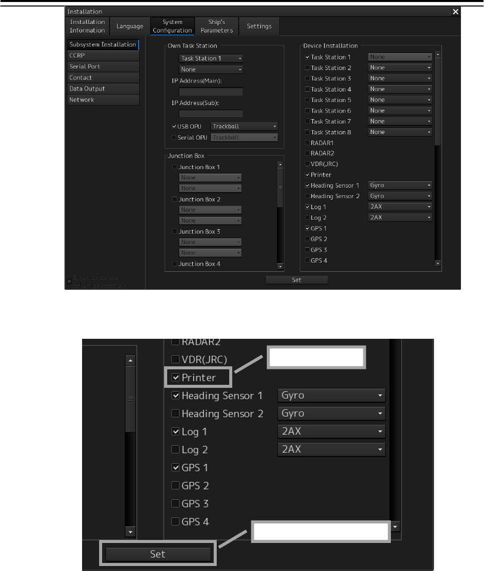
7. Check [Printer] in "Device Installation" and click the [Set] button.
1) Check
2) Click [Set]button
5.Option Unit> 5.4 Printer
5-40
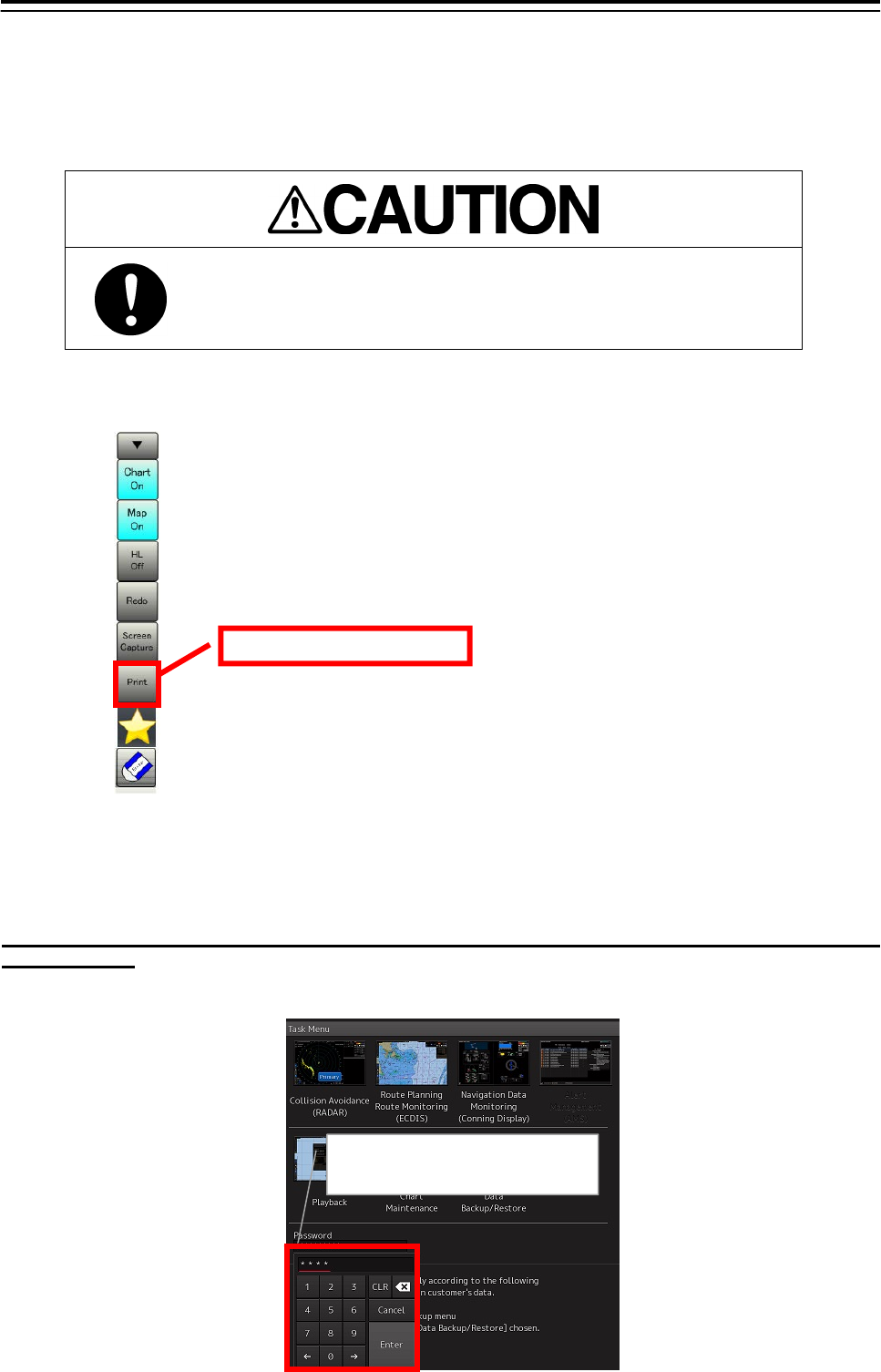
5.4.5 Confirming Printing Operation
Confirm the printer prints normally on the sheet according to the following procedures.
Since there is no print function in "Conning Display", it cannot confirm in
"Conning Display".
1. Click the [Print] button of “Left Tool Bar”.
2. Confirm a screen image on display is printed.
When the image cannot printed
Set the printer port refer to the following steps.
In this steps need the keyboard. When there is no keyboard operating unit, prepare the keyboard of a
USB interface.
1. Input the password [9999], and click the [Enter]. Task manager will open.
Input the password [9999]
and click the [Enter].
Click [Print] button

5.Option Unit> 5.4 Printer
5-41
2. Select the [File]-[New Task(Run…)].
3. Following dialog opens. Input the [explorer] and click the [OK] button.
4. Click the [Open Control Panel] from the open explorer.
Click the [Open Control Panel].
1)Input the [Explorer].
2
)
Click the 「OK」 button.
Select the [New Task(Run…)].
5.Option Unit> 5.4 Printer
5-42
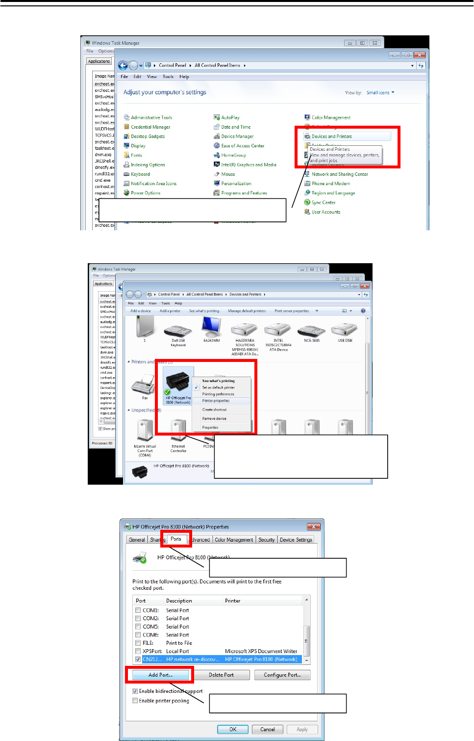
5. Click the [Devices and Printers] from [Control Panel].
6. Right-click the [HP Officejet Pro 8100(Network)] and select the [Printer properties].
7. Click the [Add Port] button from[Ports] tab.
2
)
Click the
[
Add Port...
]
.
1
)
Click the
[
Ports
]
tab.
1)Right click the [HP Officejet Pro
8100(Network].
2)select the [Printer properties].
Click the [Devices and Printers].
5.Option Unit> 5.4 Printer
5-43
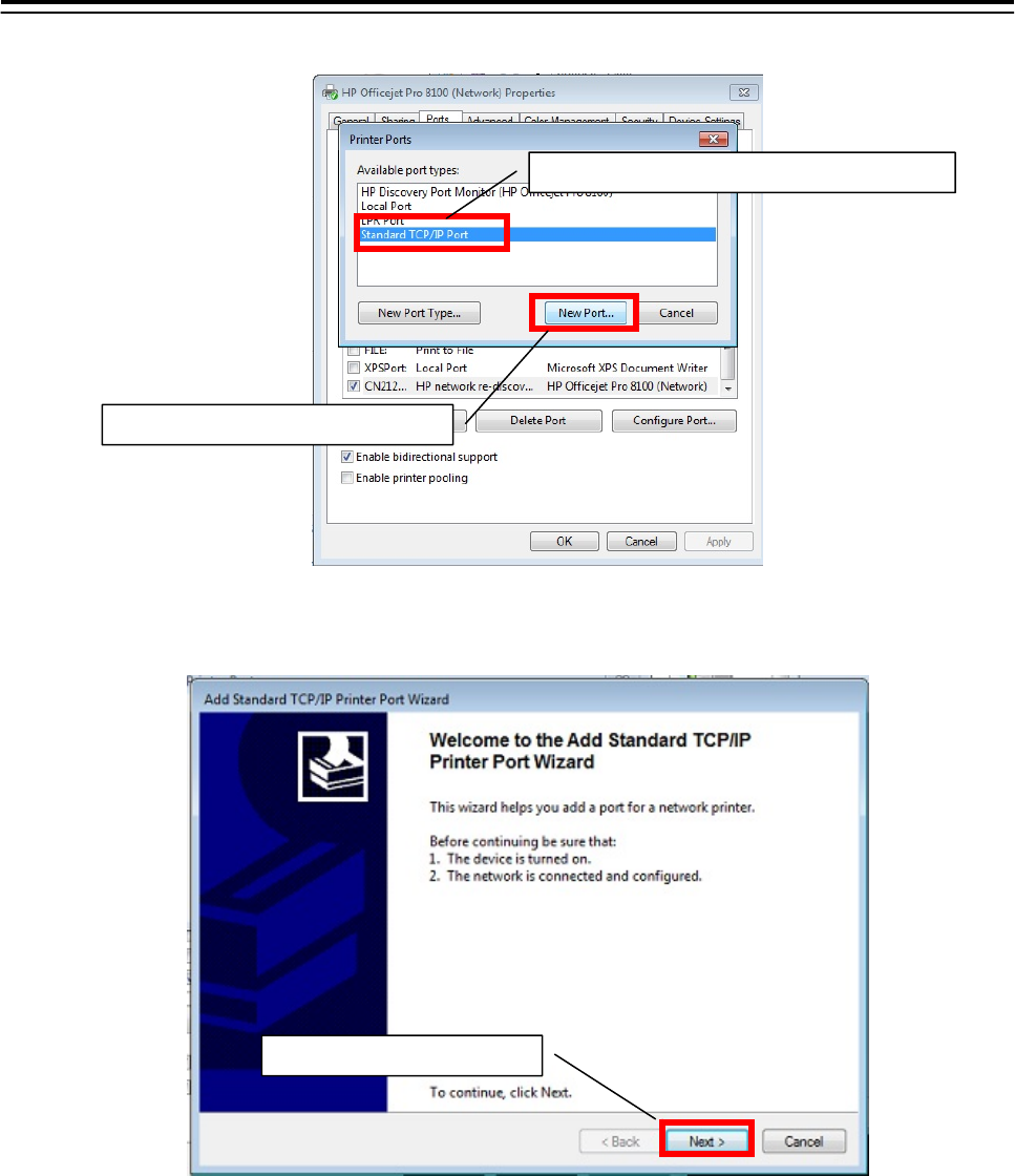
8. Select the [Standard TCP/IP Port] and click the [New Port…] button.
9. Following dialog opens. Check the printer is connected to the network and turned on.
After checking, click the [Next] button.
Click the
[
Next
]
button.
1
)
Click the
[
Standard TCP/IP Port
]
tab.
2
)
Click the
[
New Port...
]
button.
5.Option Unit> 5.4 Printer
5-44
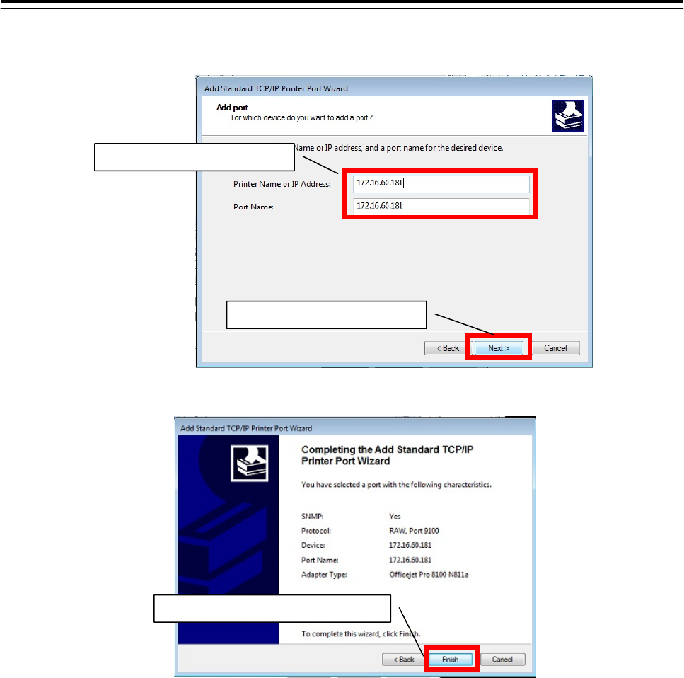
10. Input the No.1 Printer IP address-[172.16.60.181] and click the [Next] button.
When set the No.2 Printer, input the IP address [172.16.60.182].
11. Click the [Finish] button.
Setting of the printer port is end. Restart the display unit, and confirm a screen image on display is printed.
Refer to the 5.4.5 Confirming Printing Operation.
12. Set the other display unit about the printer port By the same procedure(When the image cannot
print 1-11).
Setting of the printer port is end above.
1
)
Click the
[
Finish
]
button.
2
)
Click the
[
Next
]
button.
1
)
Input the IP address.