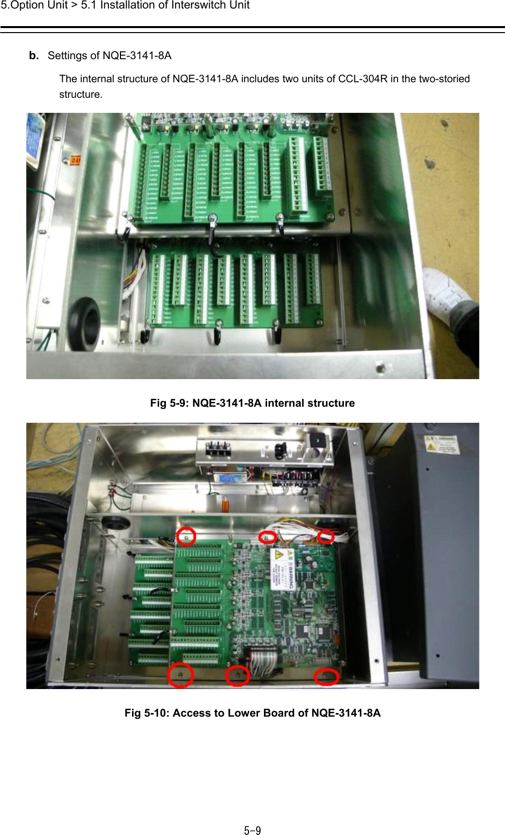
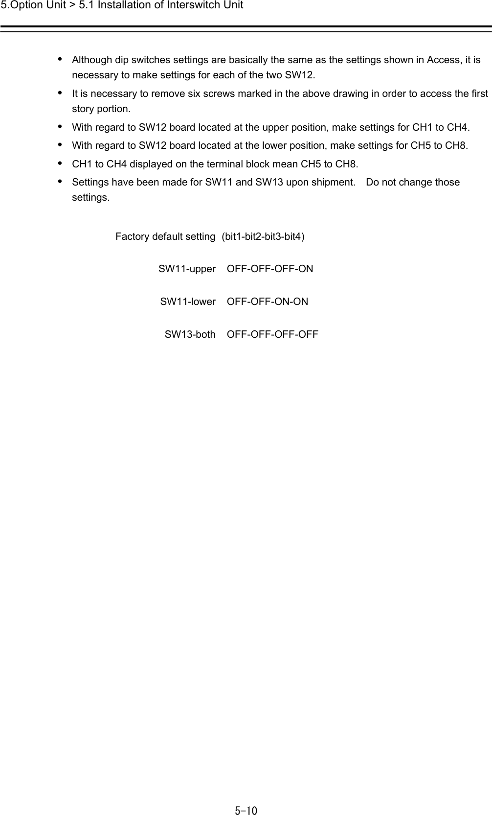
Japan Radio Co NKE2632 Solid State S-Band Marine Radar User Manual Installation Manual Part 7

Japan Radio Co Ltd. Solid State S-Band Marine Radar Installation Manual Part 7

Installation Manual Part 7

5.Option Unit > 5.1 Installation of Interswitch Unit 5-1 5.  Option Unit 5.1   Installation of Interswitch Unit  5.1.1   End processing of Interswitch cable(2695111153)   abt. 80 mm terminalInner ShieldOuter Shieldtaping1000 mmWidth for clamping cable.30 mm26951100562695111153 abt.abt. Fig 5-1: Equipment cable end processing   Fig 5-2: End processing of each cable core
5.Option Unit > 5.1 Installation of Interswitch Unit 5-2  5.1.2     Connection of equipment cable There is two type Interswitch(NQE-3141); NQE-3141-4A(4ch) and NQE-3141-8A(8ch).   Connection Procedure 1)   Ground the earth plate to the hull ground. 2)   Connect the Interswitch(NQE-3141) to the Radar I/F Circuit(CQD-2273) with the 2695111153 cable. Refer to Fig 5-5: NQE-3141-4A Inter-board connection diagram. -When connect to the JAN-901/901M/701 and third-party ECDIS.   Connnect the input terminal : VD, TRG, BP, BZ(JAN-901/901M/701 and third-party ECDIS) and output terminal : VDOUT, TRGOUT, BPOUT, BZOUT(NQE-3141).  - When connect to the JMA-9100/7100,JMA-5300MK2, JMA-900B. Connect the VD, TRG, BP, BZ, PWR terminal on JMA-9100/7100,JMA-5300MK2, JMA-900B and VD, TRG, BP, BZ, PWR terminal on the NQE-3141.  3) Refer to End processing of Interswitch cable(2695111153) for the end of processing of Interswitch cable. When connect to the Radar I/F Circuit(CQD-2273) in the Junction box(NQE-1143), fix the cable by the metal parts that surrounded by a dotted line.             Refer to the below detailed fixed position. And connect the shield of the cable to the thumbscrew or hex spacer surrounded by the circle. (Recommended crimp terminal is V5.5)  Fig 5-3 Way of fixing and grounding(2695111153) When connect to the interswitch unit, fix the shield portion of the cable by the metal parts that surrounded by the dotted line.
5.Option Unit > 5.1 Installation of Interswitch Unit 5-3  Fig 5-4 Cable inlet of the NQE-3141-8A    So that the braided shield is not shorted to the power supply terminal block, please insulate the cable and fix with cable tie. Please put the Extra length of the cable to the bottom of the display unit so that the not shorted to the UPS or SENSOR LAN switch unit.  4)  After the installation is finished, refer to the 5.1.6 Confirmation after installation and check the operation.
5.Option Unit > 5.1 Installation of Interswitch Unit 5-4  5.1.3   NQE-3141-4A Inter-board connection diagram CH-1TB911 TB912No.1 RADARRADAR I/F Circuit CQD-2273 J833/J8341234567891011121314151234567891011CH-2TB913 TB914CH-3TB915 TB916NQE-3141-4ACCL-304RISWO_VD+ISWO_VD-ISWO_TRG+ISWO_TRG-ISWO_BP+ISWO_BP-ISWO_BZ+ISWO_MTR+ISWO_MTR-ISWO_BZ-ISWO_MTRGISWI_VD+ISWI_VD-ISWI_TRG+ISWI_TRG-ISWI_BP+ISWI_BP-ISWI_BZ+ISWI_BZ-ISWI_MTR+ISWI_MTR-PWROUTPWROUTEISWI_MTRGPWRINPWRINE1234567891011123456789101112131415BLK1BLK2BLUYELGRNWHT-BLUWHT-WHTORGBLKPNKBRNREDPURCLRWHT-YELWHT-WHTBLK2REDPURCLRWHT-YELWHT-WHTBLK1BLUYELGRNWHT-BLUWHT-WHTORGBLKPNKBRNH-2695111153  (JRC SUPPLY)H-2695111153  (JRC SUPPLY)H-2695111153  (JRC SUPPLY)CH-4TB917 TB918H-2695111153  (JRC SUPPLY)J833J834ISWO_VD+ISWO_VD-ISWO_TRG+ISWO_TRG-ISWO_BP+ISWO_BP-ISWO_BZ+ISWO_MTR+ISWO_MTR-ISWO_BZ-ISWO_MTRGISWI_VD+ISWI_VD-ISWI_TRG+ISWI_TRG-ISWI_BP+ISWI_BP-ISWI_BZ+ISWI_BZ-ISWI_MTR+ISWI_MTR-PWROUTPWROUTEISWI_MTRGPWRINPWRINE1234567891011123456789101112131415BLK1BLK2BLUYELGRNWHT-BLUWHT-WHTORGBLKPNKBRNREDPURCLRWHT-YELWHT-WHTJ833J834ISWO_VD+ISWO_VD-ISWO_TRG+ISWO_TRG-ISWO_BP+ISWO_BP-ISWO_BZ+ISWO_MTR+ISWO_MTR-ISWO_BZ-ISWO_MTRGISWI_VD+ISWI_VD-ISWI_TRG+ISWI_TRG-ISWI_BP+ISWI_BP-ISWI_BZ+ISWI_BZ-ISWI_MTR+ISWI_MTR-PWROUTPWROUTEISWI_MTRGPWRINPWRINE1234567891011123456789101112131415J833J834ISWO_VD+ISWO_VD-ISWO_TRG+ISWO_TRG-ISWO_BP+ISWO_BP-ISWO_BZ+ISWO_MTR+ISWO_MTR-ISWO_BZ-ISWO_MTRGISWI_VD+ISWI_VD-ISWI_TRG+ISWI_TRG-ISWI_BP+ISWI_BP-ISWI_BZ+ISWI_BZ-ISWI_MTR+ISWI_MTR-PWROUTPWROUTEISWI_MTRGPWRINPWRINE1234567891011123456789101112131415J833J834No.2 RADARRADAR I/F Circuit CQD-2273 J833/J834No.1 ECDISRADAR I/F Circuit CQD-2273 J833/J834No.2 ECDISRADAR I/F Circuit CQD-2273 J833/J834VDINVDINETRGINTRGINEBPINBPINEBZINMTRIN+MTRIN-BZINEMTRINEPWRINPWRINEPWROUTPWROUTEVDOUTVDOUTETRGOUTTRGOUTEBPOUTBPOUTEBZOUTMTROUT+MTROUT-BZOUTEMTROUTE1234567891011121314151234567891011BLK2REDPURCLRWHT-YELWHT-WHTBLK1BLUYELGRNWHT-BLUWHT-WHTORGBLKPNKBRNVDINVDINETRGINTRGINEBPINBPINEBZINMTRIN+MTRIN-BZINEMTRINEPWRINPWRINEPWROUTPWROUTE1234567891011121314151234567891011BLK2REDPURCLRWHT-YELWHT-WHTBLK1BLUYELGRNWHT-BLUWHT-WHTORGBLKPNKBRNVDINVDINETRGINTRGINEBPINBPINEBZINMTRIN+MTRIN-BZINEMTRINEPWRINPWRINEPWROUTPWROUTE1234567891011121314151234567891011BLK2REDPURCLRWHT-YELWHT-WHTBLK1BLUYELGRNWHT-BLUWHT-WHTORGBLKPNKBRNVDINVDINETRGINTRGINEBPINBPINEBZINMTRIN+MTRIN-BZINEMTRINEPWRINPWRINEPWROUTPWROUTEBLK1BLK2BLUYELGRNWHT-BLUWHT-WHTORGBLKPNKBRNREDPURCLRWHT-YELWHT-WHTBLK1BLK2BLUYELGRNWHT-BLUWHT-WHTORGBLKPNKBRNREDPURCLRWHT-YELWHT-WHTVDOUTVDOUTETRGOUTTRGOUTEBPOUTBPOUTEBZOUTMTROUT+MTROUT-BZOUTEMTROUTEVDOUTVDOUTETRGOUTTRGOUTEBPOUTBPOUTEBZOUTMTROUT+MTROUT-BZOUTEMTROUTEVDOUTVDOUTETRGOUTTRGOUTEBPOUTBPOUTEBZOUTMTROUT+MTROUT-BZOUTEMTROUTE Fig 5-5: NQE-3141-4A Inter-board connection diagram
5.Option Unit > 5.1 Installation of Interswitch Unit 5-5  5.1.4   Installation of interswitch unit  Fig 5-6: Outline Drawing of NQE-3141-4A Interswitch Unit (4ch)
5.Option Unit > 5.1 Installation of Interswitch Unit 5-6   Fig 5-7: Outline Drawing of NQE-3141-8A Interswitch Unit (8ch)
5.Option Unit > 5.1 Installation of Interswitch Unit 5-7  5.1.5   Settings of Interswitch Since settings have been normally made upon shipment from factory, it is advised to only confirm the settings. a.  Settings of NQE-3141-4A Set dip switches SW11, SW12, and SW13 as shown below. SW11SW13SW12 Fig 5-8: CML-304R DIP Switch  1)   SW11 setting (expansion mode, master/slave setting) Set all OFF.
5.Option Unit > 5.1 Installation of Interswitch Unit 5-8  2)  SW12 setting (radar connection setting)   Radar Connection Setting  1 ON No. 1 display unit connected OFF  No. 1 display unit NOT connected 2 ON No. 1 antenna connectedd OFF  No. 1 antenna NOT connected 3 ON No. 2 display unit connected OFF  No. 2 display unit NOT connected 4 ON No. 2 antenna connected OFF  No. 2 antenna NOT connected 5 ON No. 3 display unit connected OFF  No. 3 display unit NOT connected 6 ON No. 3 antenna connected OFF  No. 3 antenna NOT connected 7 ON No. 4 display unit connected OFF  No. 4 display unit NOT connected 8 ON No. 4 antenna connected OFF  No. 4 antenna NOT connected  3) SW13 (unused) Set all OFF.
5.Option Unit > 5.1 Installation of Interswitch Unit 5-9  b.  Settings of NQE-3141-8A The internal structure of NQE-3141-8A includes two units of CCL-304R in the two-storied structure.  Fig 5-9: NQE-3141-8A internal structure  Fig 5-10: Access to Lower Board of NQE-3141-8A
5.Option Unit > 5.1 Installation of Interswitch Unit 5-10  •   Although dip switches settings are basically the same as the settings shown in Access, it is necessary to make settings for each of the two SW12. •   It is necessary to remove six screws marked in the above drawing in order to access the first story portion.   •   With regard to SW12 board located at the upper position, make settings for CH1 to CH4. •   With regard to SW12 board located at the lower position, make settings for CH5 to CH8.   •   CH1 to CH4 displayed on the terminal block mean CH5 to CH8.   •   Settings have been made for SW11 and SW13 upon shipment.    Do not change those settings.   Factory default setting (bit1-bit2-bit3-bit4) SW11-upper  OFF-OFF-OFF-ON  SW11-lower  OFF-OFF-ON-ON  SW13-both  OFF-OFF-OFF-OFF
5.Option Unit > 5.1 Installation of Interswitch Unit 5-11  •   Settings of upper CCL-304R, SW12 (radar connection setting)     1 ON No. 1 display unit connected OFF  No. 1 display unit NOT connected 2 ON No. 1 antenna connected OFF  No. 1 antenna NOT connected 3 ON No. 2 display unit connected OFF  No. 2 display unit NOT connected 4 ON No. 2 antenna connected OFF  No. 2 antenna NOT connected 5 ON No. 3 display unit connected OFF  No. 3 display unit NOT connected 6 ON No. 3 antenna connected OFF  No. 3 antenna NOT connected 7 ON No. 4 display unit connected OFF  No. 4 display unit NOT connected 8 ON No. 4 antenna connected OFF  No. 4 antenna NOT connected
5.Option Unit > 5.1 Installation of Interswitch Unit 5-12  •   Setting of lower CCL-304R, SW12 (radar connection setting)     1 ON No. 5 display unit connected OFF  No. 5 display unit NOT connected 2 ON No. 5 antenna connected OFF  No. 5 antenna NOT connected 3 ON No. 6 display unit connected OFF  No. 6 display unit NOT connected 4 ON No. 6 antenna connected OFF  No. 6 antenna NOT connected 5 ON No. 7 display unit connected OFF  No. 7 display unit NOT connected 6 ON No. 7 antenna connected OFF  No. 7antenna NOT connected 7 ON No. 8 display unit connected OFF  No. 8 display unit NOT connected 8 ON No. 8 antenna connected OFF  No. 8 antenna NOT connected  5.1.6   Confirmation after installation  1)   After having checked connections, turn on the switchboard breaker. 2)  Turn on the power to the radar display unit, and make sure that the interswitch button is displayed on the screen and pressing the button will switch antennas.   3)  When a system consists of two devices, make sure that both left and right radars conform to the screen indication.   4)  When a system consists of three devices, make sure that the CH number and the display unit position are arranged as intended.
5.Option Unit > 5.2 Installation of Power Control Unit 5-13  5.2   Installation of Power Control Unit Power control unit NQE-3167 is used when an antenna and a transmitter-receiver are installed at a location away from the bridge, such as a foremast.   In the case of a two-unit type antenna, the maximum length of the cable that connects between the display unit and the antenna is 65 meters.    In the case of a three-unit type antenna, the maximum length of the cable that connects between the display unit and the transmitter-receiver is 35 meters.   By using NQE-3167 power control unit, the maximum length of the cable that connects between the display unit and the antenna (transmitter-receiver) can be extended up to 465 meters. Maximum length of the cable connecting between the antenna and the transmitter-receiver 30m Maximum length of the cable connecting between the transmitter-receiver and the PCU (NQE-3167) 35m Maximum length of the cable connecting between the display unit and the PCU (NQE-3167) 400m  5.2.1   Connection with NKE-2103 type and NKE-2254-6HS type scanner units Use 19-core composite cable CFQ-6912-** for the installation of those types of antennas (Asterisks ** use the cable length, and the available cable length is 5, 10, 20, 30, 40, 50, and 65) The display-unit side end of this cable is a metal shell round connector. (See 2.1.1CFQ-6912-** ) Connect that cable to J2 of the power control unit. If the metal shell round connector is cut, connect the cable to TB3 located in the power control unit.    For procedures for processing the cable end, see Section 2.1.4 Cable end processing method. With regard to six devices, such as MOTOR+ (2P), MOTOR-(2P), 1A (+48V), and 2A (48VG), two AWG16 cables must be connected to one terminal block.    As necessary, use a bar-mould crimp-type terminal or the like. (See Fig 5-11: Connection of CFQ-6912) The connection between scanner unit and AC/DC converter NBA-5135 is not necessary.   Instead, power control unit NQE-3167 supplies DC power.
5.Option Unit > 5.2 Installation of Power Control Unit 5-14   Fig 5-11: Connection of CFQ-6912
5.Option Unit > 5.2 Installation of Power Control Unit 5-15  5.2.2   Connections to NKE-1125, NTG-3225, NKE-1130, NTG-3230, NKE-1632 and NKE-2632 Use 14-core composite cable 2695110056 for the installation of those types of antennas. For the procedures for processing the cable end, see Fig 5-12: Equipment cable end processing. For the wiring procedures, see 5.2.7 Inter –board connection diagram of power control unit.  5.2.3   End processing of 2695110056 cable abt. 80 mm terminalInner ShieldOuter Shieldtaping1000 mmWidth for clamping cable.30 mm26951100562695111153 abt.abt. Fig 5-12: Equipment cable end processing 5.2.4   End processing of each cable core  Fig 5-13: End processing of each cable core 5.2.5   Connection to display unit Use 14-core composite cable 2695110056 and coaxial cable RG-10/UY to connect power control unit NQE-3167 to each display unit. Among the two cables, use coaxial cable RG-10/UY to connect the radar video signal.   For the procedures for processing the cable end and the wiring procedures, see Fig 5-12: Equipment cable end processing. For the wiring procedures, see 5.2.7 Inter –board connection diagram of power control unit.
5.Option Unit > 5.2 Installation of Power Control Unit 5-16  5.2.6   Outline Drawing of NQE-3167 Power Control Unit  Fig 5-14: Outline Drawing of NQE-3167 Power Control Unit
5.Option Unit > 5.2 Installation of Power Control Unit 5-17  J2EARTH PLATE Fig 5-15: NQE-3167 cable entrance   Fig 5-16: NQE-3167 terminal block  Securely ground the included earth plate to the hull's earth.
5.Option Unit > 5.2 Installation of Power Control Unit 5-18  5.2.7   Inter –board connection diagram of power control unit 5.2.7.1  Inter-board connection diagram of JMR-9230-S3, JMR-7230-S3
5.Option Unit > 5.2 Installation of Power Control Unit 5-19  5.2.7.2  Inter-board connection diagram of JMR-9230-S, JMR-7230-S
5.Option Unit > 5.2 Installation of Power Control Unit 5-20  5.2.7.3  Inter-board connection diagram of JMR-9272-S, JMR-7272-S J2
5.Option Unit > 5.2 Installation of Power Control Unit 5-21  5.2.7.4  Inter-board connection diagram of JMR-9282-S/SH, JMR-7282-S/SH J2
5.Option Unit > 5.2 Installation of Power Control Unit 5-22  5.2.7.5  Inter-board connection diagram of JMR-9225-7X3/9X3, JMR-7225-7X3/9X3 J2
5.Option Unit > 5.2 Installation of Power Control Unit 5-23  5.2.7.6  Inter-board connection diagram of JMR-9225-6X/9X, JMR-7225-6X/9X
5.Option Unit > 5.2 Installation of Power Control Unit 5-24  5.2.7.7  Inter-board connection diagram of JMR-9225-6XH, JMR-7225-6XH (X-BAND 25kW RADAR)JMR-9225-6XH,JMR-7225-6XHレーダー パワーコントロールユニット間 盤間接続図19-CORES COMPOSITE CABLE (JRC SUPPLY)CFQ-6912-**21MTRE23BZ+4BZ-5TRG+6TRG-7BP+8BP-910MTR+MTR-TB234ORNWHT48VG/TRX-1112+48V/TRX+HTR1314HTISR1516ISVHINUHOUTUINVINWINUHINVHOUTUOUTVOUTWOUTFARM+FARM-VD+VD-TB1 TB3POWER CONTROL UNITNQE-3167SHIP’S MAINSAC100-115V/AC220-240V 50/60Hz 1φ0.6/1kV-DPYCY-6COAXIAL CABLE for VIDEO (JRC SUPPLY)RG-10/UY          400m MAX14-CORES COMPOSITE CABLE (JRC SUPPLY)H-2695110056   400m MAX2A1AJ4J5J22A1AVDVDE2A1AJ3J1PTIPTETXITXELVRPMSEP82P81PTIPTETXITXELVRPMSEP2P1SCANNER UNITNKE-2254-6HSPERFORMANCEMONITORNJU-85WHTBRNBLUREDBLKWHTBRNBLUREDBLKBLK.T/SKY.TYEL.T/PNK.TORNGRNBLKWHTYELPUR.T/BRN.TRED.T/GRN.TWHT.T/ORN.TBLU.T/GRY.T123UVUTHTB105CIRCUIT BREAKER5A (SHIP YARD SUPPLY)0.6/1kV-DPYCYS-1.5AC100V,1φ,100WNBL-175STEP-DOWN TRANSFORMER0.6/1kV-DPYCYS-1.50.6/1kV-DPYCYS-1.5 SHIP’S MAINSAC220V, 50/60Hz, 1φ,for HEATER“D”HEATER OPTIONWiring of PERFORMANCE MONITORis completed.0.6/1kV-DPYCYS-1.5INTERCONNECTION DIAGRAM OF BETWEEN RADAR TYPE JMR-9225-6XH/JMR-7225-6XHand NQE-3167 POWER CONTROL UNIT12BP-23VDE42TRG5MT+6MT-7MTE8VD9102TGE2BP+GND11122BZ-2A13141AM+1516M+2BZ+M-1718M-MTR+MTR-TIYTIYEBPBPEBZBZE1VD+2VD-3TRIG+4TRIG-5BP+6BP-7BZ+8BZ-9MTR+10 MTR-11 MTRG12 (N.C.)13 DC+14 DC-J832JUNCTION BOXNQE-1143CQD-2273 Radar Interface CircuitNO CONNECTIONREDBLU3ORNWHT24TB8382 V1 UNO CONNECTIONTB8402 -1 +J837J839J831RIFDC_SC_INAC_SC_INTo PSU W853:7ZCNA4160To CCU CML-836-DCW841:7ZCNA4164NO CONNECTION
5.Option Unit > 5.2 Installation of Power Control Unit 5-25  5.2.7.8  Inter-board connection diagram of JMR-9210-6X/6XH, JMR-7210-6X/6XH
5.Option Unit> 5.3 Connection of VDR 5-26  5.3   Connection of VDR 5.3.1   Connection with LAN (IEC61162-450) When the VDR have LAN port, use connection with the LAN (IEC61162-450). There is the LAN port J4122 which is located in central control unit (NDC-1590). See the drawing below.  Fig 5-17 VDR connection connector LAN(IEC61162-450) After the connection, please set the display unit refers to the 4.15 Setting of VDR.  5.3.2   Connection with Analog RGB When the VDR does not have LAN port, use connection with Analog RGB. Analog RGB signal for VDR is output from J4205 which is located in the central control unit (NDC-1590). See the drawing below.    Fig 5-18: VDR connection connector Analog RGB
5.Option Unit> 5.4 Printer 5-27  5.3.2.1  VDR I/F kit The VDR I/F kit is used to connection with analog RGB. VDR I/F kit CQD-1891 includes: DSUB15P - BNC cable (KB5BNC2K, 2 meters)  1 pcs BNC to BNC adapter (BNC-A-JJ)  5 pcs BNC connector (3CV-P2)  5 piece  5 pcs Use 3C-2V coaxial cable for connection.   REDGRNBLUGRYBLKRED :redGRN :greenBLU :blueGRY :HSYNCBLK :VSYNCKB-5BNC2KBNC BNC-A-JJBNCBNCBNCBNCBNC-A-JJBNC-A-JJBNC-A-JJBNC-A-JJ3C-2V3C-2V3C-2V3C-2V3C-2V3CV-P23CV-P23CV-P23CV-P23CV-P2CQD-1891TO VDRNDC-1590J4205 Fig 5-19: CQD-1891 VDR I/F Kit
5.Option Unit> 5.4 Printer 5-28  5.4   Printer Set the printer accoding to the following procedures.   When there is no keyboard operating unit, prepare the keyboard of a USB interface.   There is a procedure that cannot be set for the keyboard not to exist.   5.4.1   Printer Composition  Externals of the printer are as follows.                    ●Necessary for setting    No  名称 備考 1 Start Poster   2 AC Adaptor   3  CD for Printer Driver   4  Two sided of automatic op-eration print accessories  5 Ink   6 Printer Head   7 Print Paper   8 USB Keyboard When NCE-5625 Keyboard Operation Unit is not equipped.  ●Not necessary for setting  No  名称 備考   LAN Cable  It doesn't use.   Use the specified LAN cable.   USB Cable  It doesn't use.   Warranty Card  Please keep it with the ship importantly.   Directions of print paper  Please keep it with the ship importantly.  Support documentation  Please keep it with the ship importantly.
5.Option Unit> 5.4 Printer 5-29  5.4.2   Printer Assembly  Assemble a printer according to the following procedures.  ①    Set up the printer according to attached “Start” poster.           ②  Set some papers and push the power button.   Power button
5.Option Unit> 5.4 Printer 5-30  5.4.3   Setting Printer  The setting method of the printer is described.   Set the printer according to the following procedures.   5.4.3.1  Connecting Power Cable and Printer LAN Cable  Connect power cable and printer LAN cable with the printer and main hub unit respectively. Con-necting location is described to “Start” poster.    Connecting location of power cable    Connecting location of LAN cable  5.4.3.2  Confirming Printer IP Address  Confirm IP address of the printer according to the following procedures.  1. Power on Printer and ECDIS.  2. Keep pressing “Resume” button and “Wireless” button (see below diagram) at the same time.  Confirm that 2 pieces of paper ” HP Network Configuration Page” are printed.  “Resume” but-“Wireless” button
5.Option Unit> 5.4 Printer 5-31   3. Confirm default ”IP Address” and ”Subnet Mask” on the “HP Network Configuration Page”.    5.4.3.3  Setting Printer IP Address  Set up the IP address of the printer according to the following procedures.  1. Power on this equipment.  2. After the default task starts, click the [Menu] button of the “Left Tool Bar”. The “Menu” dialog is displayed. Default ”IP Address” and ”Subnet Mask” IP Address  Subnet Mask ex)
5.Option Unit> 5.4 Printer 5-32  3. Click [Code Input] button. The “Password” dialog is displayed.    4. After the password "0009" is input with the software keyboard, click the [Enter] button. The [service] button is added to the menu. Once the [Service] button is added, it will be dis-played until the task menu is finished.   5. Click the [Service] button of the “Menu” dialog. The sub menu of [Service] is displayed.   6. Click the [Installation] button. The “Installation” dialog is displayed.
5.Option Unit> 5.4 Printer 5-33  7. [System Configuration] is chosen by the first classification pane, and [Network] is chosen by the second classification pane. The “Network” dialog is displayed on the edit pane. Make a note of the present IP address.   8. According to the following explanation, input the IP address of "Own Task Station" and click the [Set] button.   9. Click the  [Code Input]  button of the “Menu” dialog. And after the password "9999" is input with the software keyboard, click the [Enter] button. The task is finished and it returns to the task menu screen. 1st to 3rd octet Input the default IP address of the printer. 4th octet Input a different value from the default IP address of the printer. Click after input Make a note of the IP address.
5.Option Unit> 5.4 Printer 5-34  10. Input the password "0913" into the “Code input” box of the task menu screen. The “Internet Explore” is displayed.   11. Input [http://IP address of printer] into the address bar.  “HP Officejet Pro 8100 N811a” page is displayed.
5.Option Unit> 5.4 Printer 5-35   Note:  When following error is displayed, delete “Temporary Internet files” as follows.  1)  Start Internet explorer again. Select "Tools" - “Internet Options…" 2)  “Internet Options" dialog is displayed. Click [Delete...] button. Click [Delete...] button 1) Select "Tools". 2) Select “Internet Options…".
5.Option Unit> 5.4 Printer 5-36 3)  “Delete Browsing History” dialog is displayed. Check “Temporary Internet Files” and click [Delete] button.   12. Click [Network] and select ”IPv4”of ”Wired (802.3)”.    13. Enter “Manual IP Address”, ”Manual Subnet Mask” and “Manual Default Gate-way” according to bellow diagram. After enter the value, click   button.  1) Click ”Network” tab 2) Select ”IPv4” 1) Check "Temporary Internet files" 2) Click [Delete] button
5.Option Unit> 5.4 Printer 5-37     No.1 Printer  No.2 Printer IP Address  172.16.60.181  172.16.60.182 Subnet Mask  255.255.0.0  255.255.0.0 Default Gateway  172.16.60.225  172.16.60.225   14. After setup, close the "Internet Explore" and start a task.  15. Return the IP address of this equipment to the original value according to the proce-dure of 8.  16. The IP address assigned for the printer setup is added to Network List of the Network dialog. Check the line of relevance and click the [Delete] button.  1) Check 2) Click  [Delete]button
5.Option Unit> 5.4 Printer 5-38  5.4.4   Equipment setup  The existence of a printer is set up by equipment setup of a subsystem.  Change the equipment setup of the subsystem in the “Subsystem Installation” dialog.  Note: Refer to 4.4 "Subsystem Installation".   1. Click the [Menu] button of the “Left Tool Bar”. The “Menu” dialog is displayed.  2. Click [Code Input] button. The “Password” dialog is displayed.   3. After the password "0009" is input with the software keyboard, click the [Enter] button. The [service] button is added to the menu. Once the [Service] button is added, it will be dis-played until the task menu is finished.  4. Click the [Service] button of the “Menu” dialog. The sub menu of [Service] is displayed.   5. Click the [Installation] button. The “Installation” dialog is displayed.         6. [System Configuration] is chosen by the first classification pane, and [Subsystem Instal-lation] is chosen by the second classification pane.   The “Subsystem Installation” dialog is displayed on the edit pane.
5.Option Unit> 5.4 Printer 5-39    7. Check [Printer] in "Device Installation" and click the [Set] button.  1) Check 2) Click  [Set]button
5.Option Unit> 5.4 Printer 5-40  5.4.5   Confirming Printing Operation  Confirm the printer prints normally on the sheet according to the following procedures.   Since there is no print function in "Conning Display", it cannot confirm in "Conning Display".   1. Click the  [Print]  button of “Left Tool Bar”.   2. Confirm a screen image on display is printed.  When the image cannot printed Set the printer port refer to the following steps.  In this steps need the keyboard. When there is no keyboard operating unit, prepare the keyboard of a USB interface.    1.  Input the password [9999], and click the [Enter]. Task manager will open.  Input the password [9999] and click the [Enter]. Click  [Print] button
5.Option Unit> 5.4 Printer 5-41  2.  Select the [File]-[New Task(Run…)].   3.  Following dialog opens. Input the [explorer] and click the [OK] button.    4.  Click the [Open Control Panel] from the open explorer.   Click the [Open Control Panel].1)Input the [Explorer]. 2)Click the  「OK」 button. Select the [New Task(Run…)].
5.Option Unit> 5.4 Printer 5-42  5.  Click the [Devices and Printers] from [Control Panel].   6.  Right-click the [HP Officejet Pro 8100(Network)] and select the [Printer properties].   7.  Click the [Add Port] button from[Ports] tab. 2)Click the [Add Port...].1)Click the [Ports] tab.1)Right click the [HP Officejet Pro 8100(Network]. 2)select the [Printer properties]. Click the [Devices and Printers].
5.Option Unit> 5.4 Printer 5-43  8.  Select the [Standard TCP/IP Port] and click the [New Port…] button.   9.  Following dialog opens. Check the printer is connected to the network and turned on. After checking, click the [Next] button.   Click the [Next] button.1)Click the [Standard TCP/IP Port] tab.2)Click the [New Port...] button.
5.Option Unit> 5.4 Printer 5-44  10.  Input the No.1 Printer IP address-[172.16.60.181] and click the [Next] button. When set the No.2 Printer, input the IP address [172.16.60.182].    11.  Click the [Finish] button.    Setting of the printer port is end. Restart the display unit, and confirm a screen image on display is printed. Refer to the 5.4.5 Confirming Printing Operation.  12.  Set the other display unit about the printer port By the same procedure(When the image cannot print 1-11).  Setting of the printer port is end above. 1)Click the [Finish] button.2)Click the [Next] button.1)Input the IP address.

Navigation menu