Japan Radio Co NKE2632 Solid State S-Band Marine Radar User Manual Installation Manual Part 5
Japan Radio Co Ltd. Solid State S-Band Marine Radar Installation Manual Part 5
Contents
- 1. Installation Manual Part 1
- 2. Installation Manual Part 2
- 3. Installation Manual Part 3
- 4. Installation Manual Part 4
- 5. Installation Manual Part 5
- 6. Installation Manual Part 6
- 7. Installation Manual Part 7
- 8. Installation Manual Part 8
- 9. Installation Manual Part 9
- 10. Installation Manual Part 10
- 11. Installation Manual Part 11
- 12. Instruction Manual Operation Part 1
- 13. Instruction Manual Operation Part 2
- 14. Instruction Manual Operation Part 3
- 15. Instruction Manual Operation Part 4
- 16. Instruction Manual Funtion Part 1
- 17. Instruction Manual Funtion Part 2
- 18. Instruction Manual Funtion Part 3
- 19. Instruction Manual Funtion Part 4
- 20. Instruction Manual Funtion Part 5
- 21. Instruction Manual Funtion Part 6
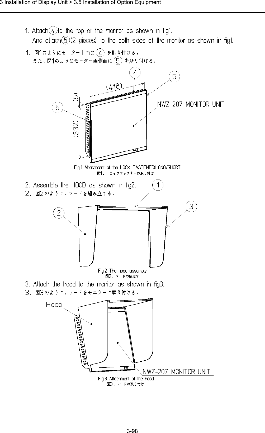
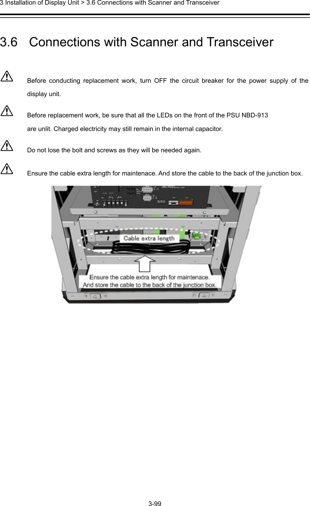
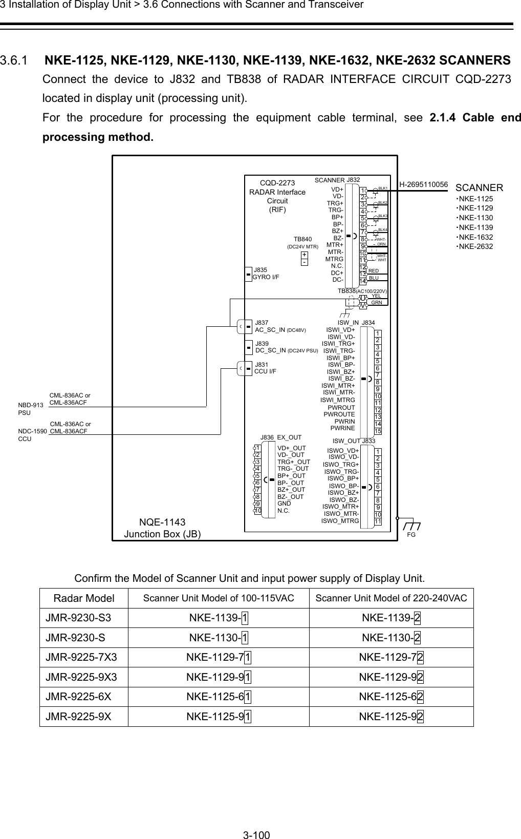
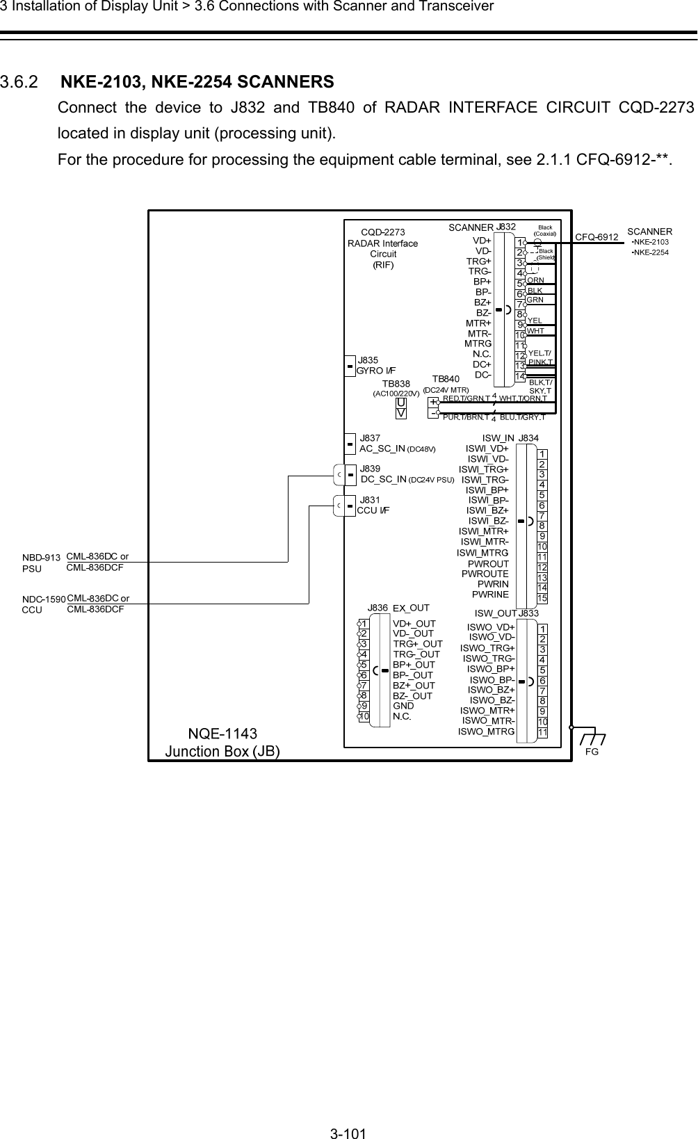
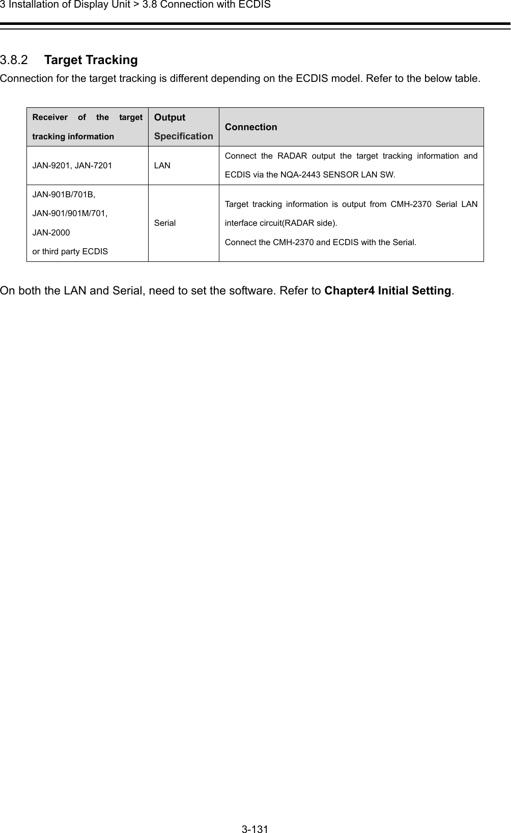
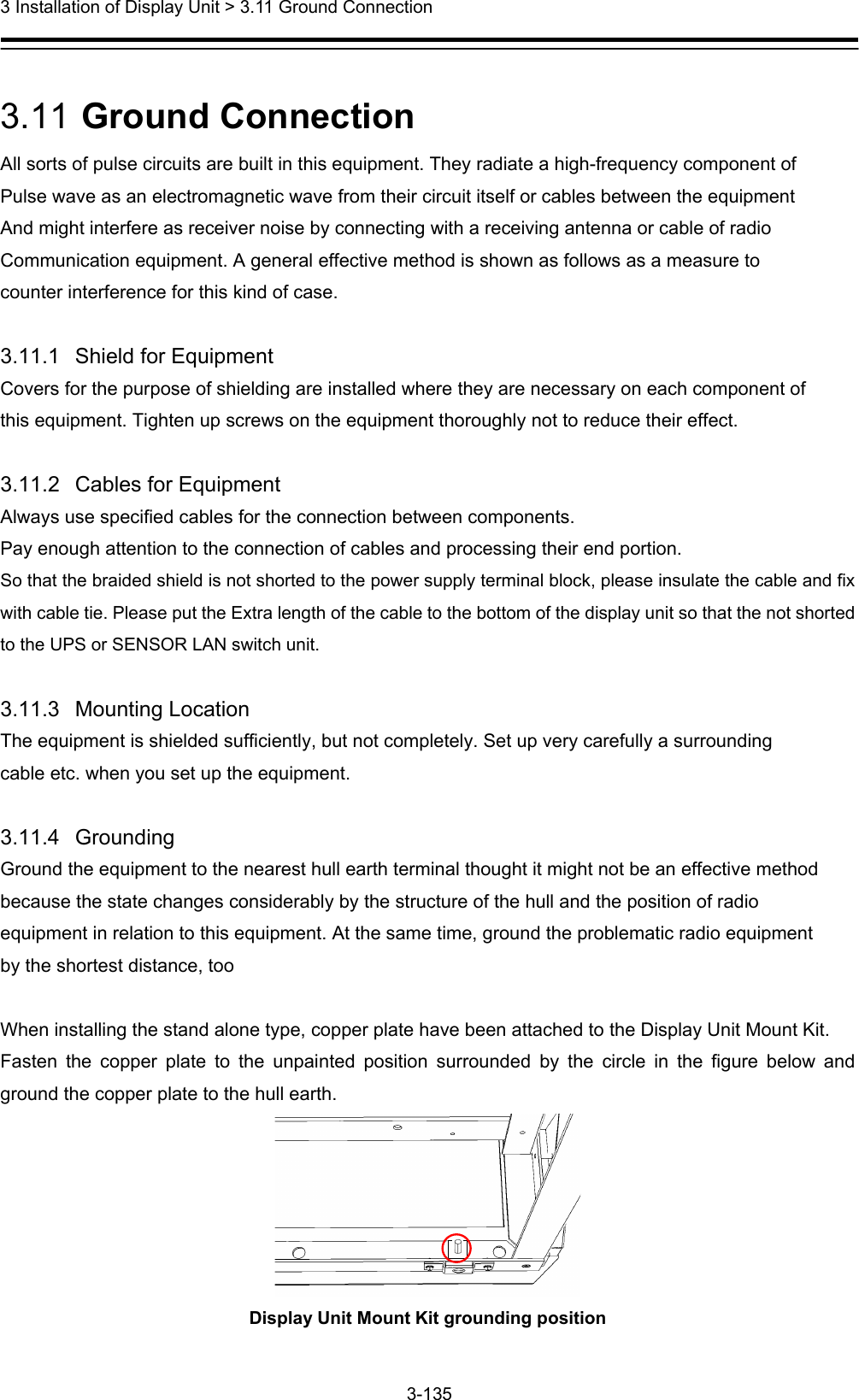
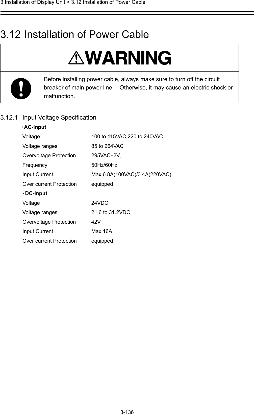
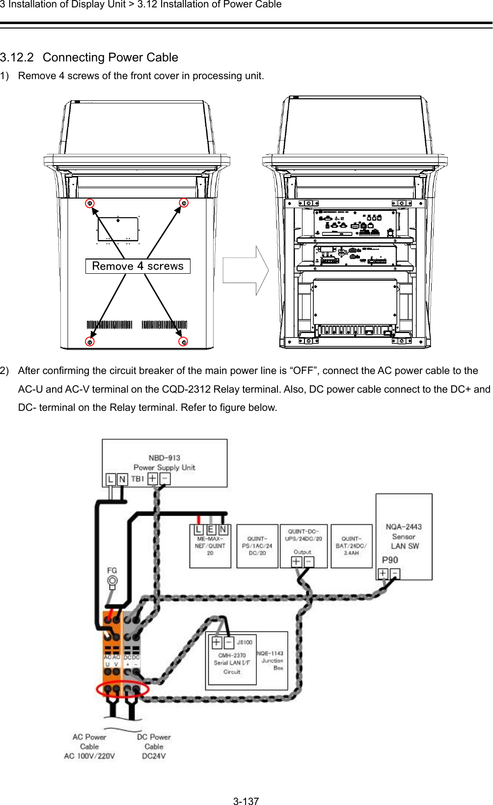
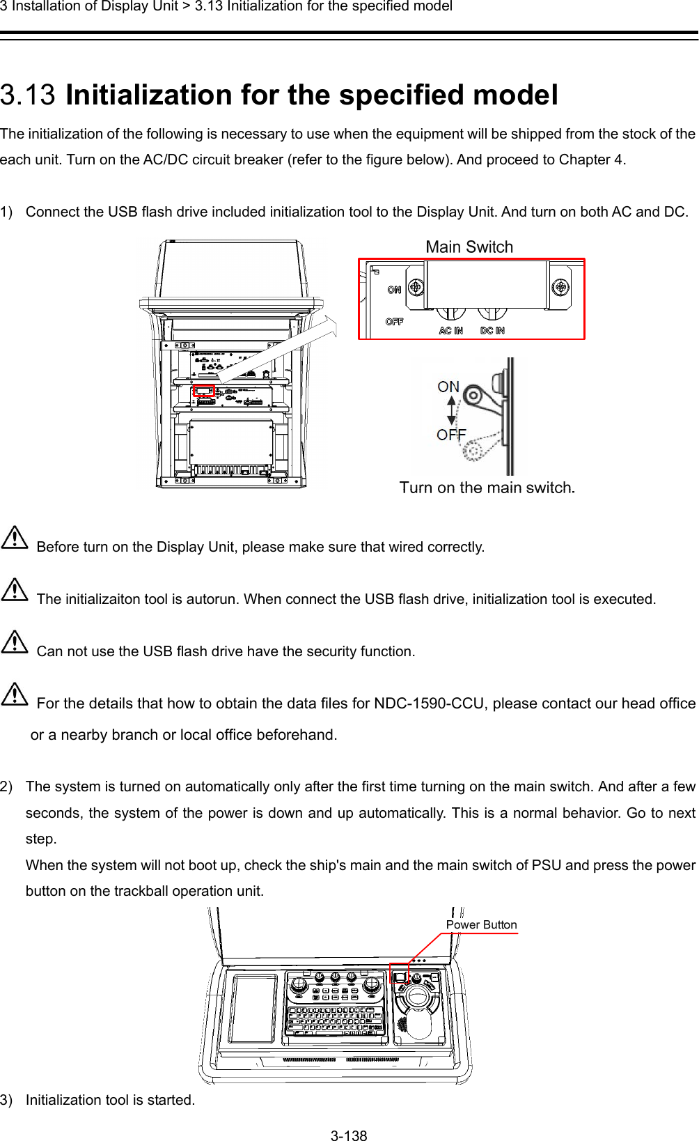
Installation Manual Part 5

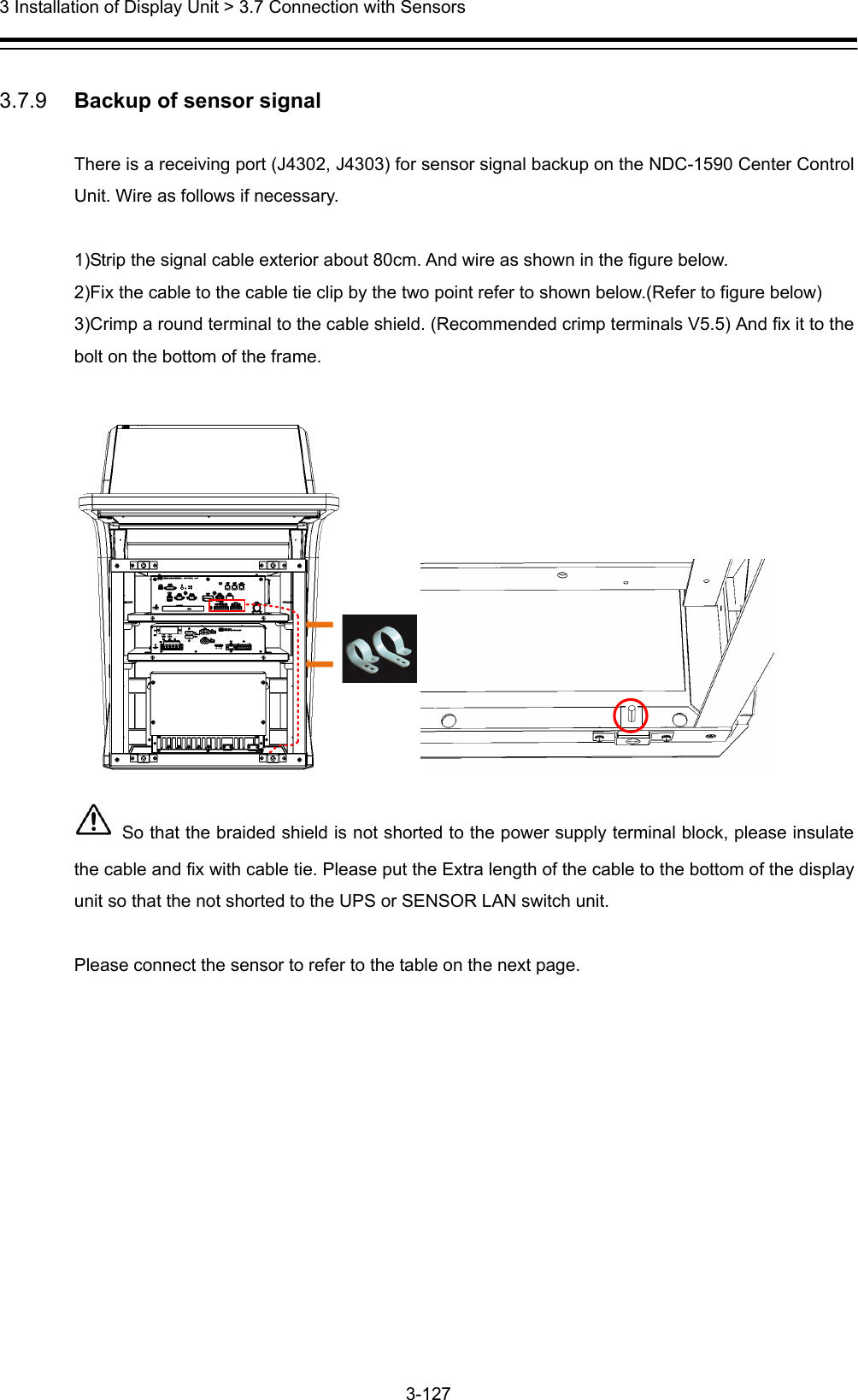
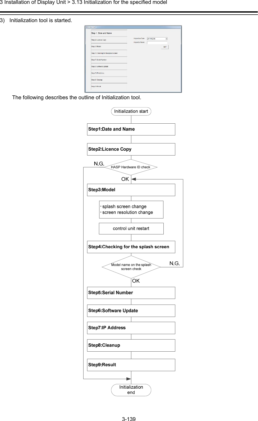
![3 Installation of Display Unit > 3.13 Initialization for the specified model 3-140 4) Initialize according to the following procedures before using the equipment. Step1: Date and Name Input the inspector date, inspector name. And then click the [SET] button. Step2: Licence Copy The Hardware ID of HASP is compared with the Hardware ID in the licence file. If they match, the licence file is copied over. HASP: Hardware Against Software Piracy (included NDC-1590 Central Control Unit) If they mismatch, following dialog is displayed.](https://usermanual.wiki/Japan-Radio-Co/NKE2632.Installation-Manual-Part-5/User-Guide-2791038-Page-47.png)
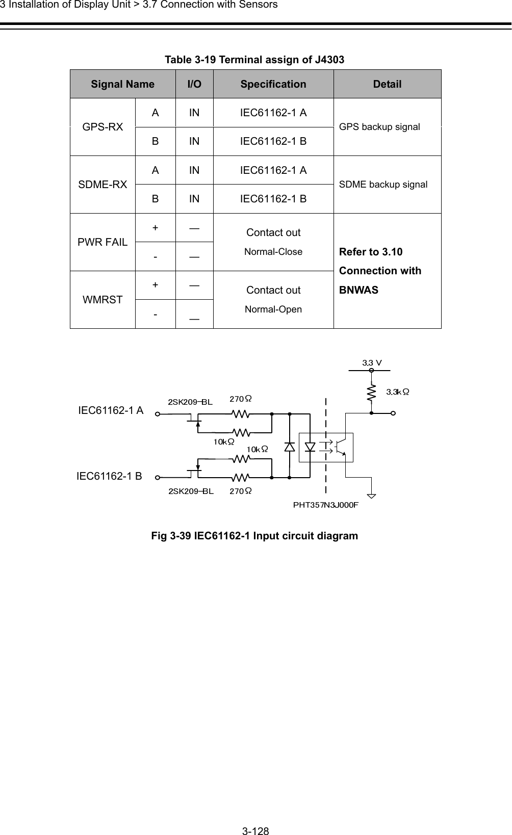
![3 Installation of Display Unit > 3.13 Initialization for the specified model 3-141 Step3: Model Select each item from the drop-down list. Model name is displayed in the Model window. And then click the [SET] button. After clicking the [SET] button, the following image is displayed. a) When installing the stand alone type Paste the Name Label same as the image to the position shown in the figure below. All model name label each two have been attached to the display unit. Please discard the label which model name does not match or remained. In case of JMR-9230-S](https://usermanual.wiki/Japan-Radio-Co/NKE2632.Installation-Manual-Part-5/User-Guide-2791038-Page-48.png)
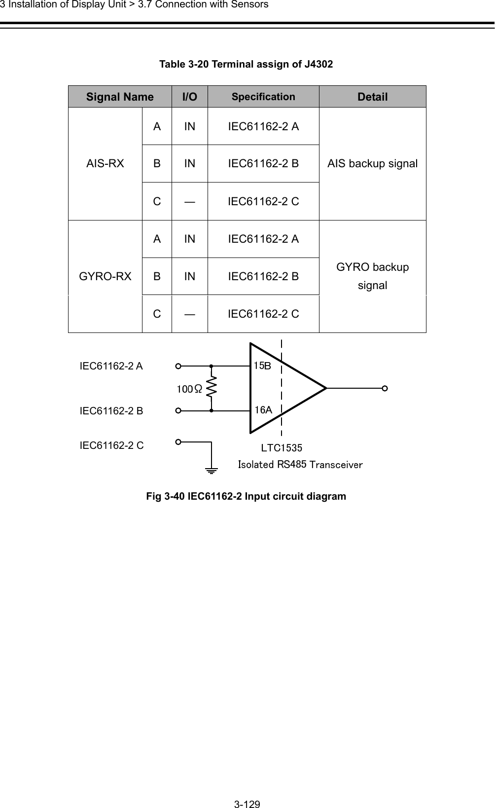
![3 Installation of Display Unit > 3.13 Initialization for the specified model 3-142 b) When installing the desktop type or flush mount type All model name label each two have been attached to the display unit. Paste the Name Label same as the image to the position shown in the figure below. Back the other label of the same model name to the bag and attach the bag to the NDC-1590. Please discard the label which model name does not match. Name label pasting position After pasting, please press the [OK] button. The following screen is displayed and start-up screen will be changed automatically. It will take a few minutes to process. Please press any key because it is a key input required at the end. After processing, please press any key because key input required at the end. Resolution and splash screen is automatically changed, and then the following dialog is displayed.](https://usermanual.wiki/Japan-Radio-Co/NKE2632.Installation-Manual-Part-5/User-Guide-2791038-Page-49.png)
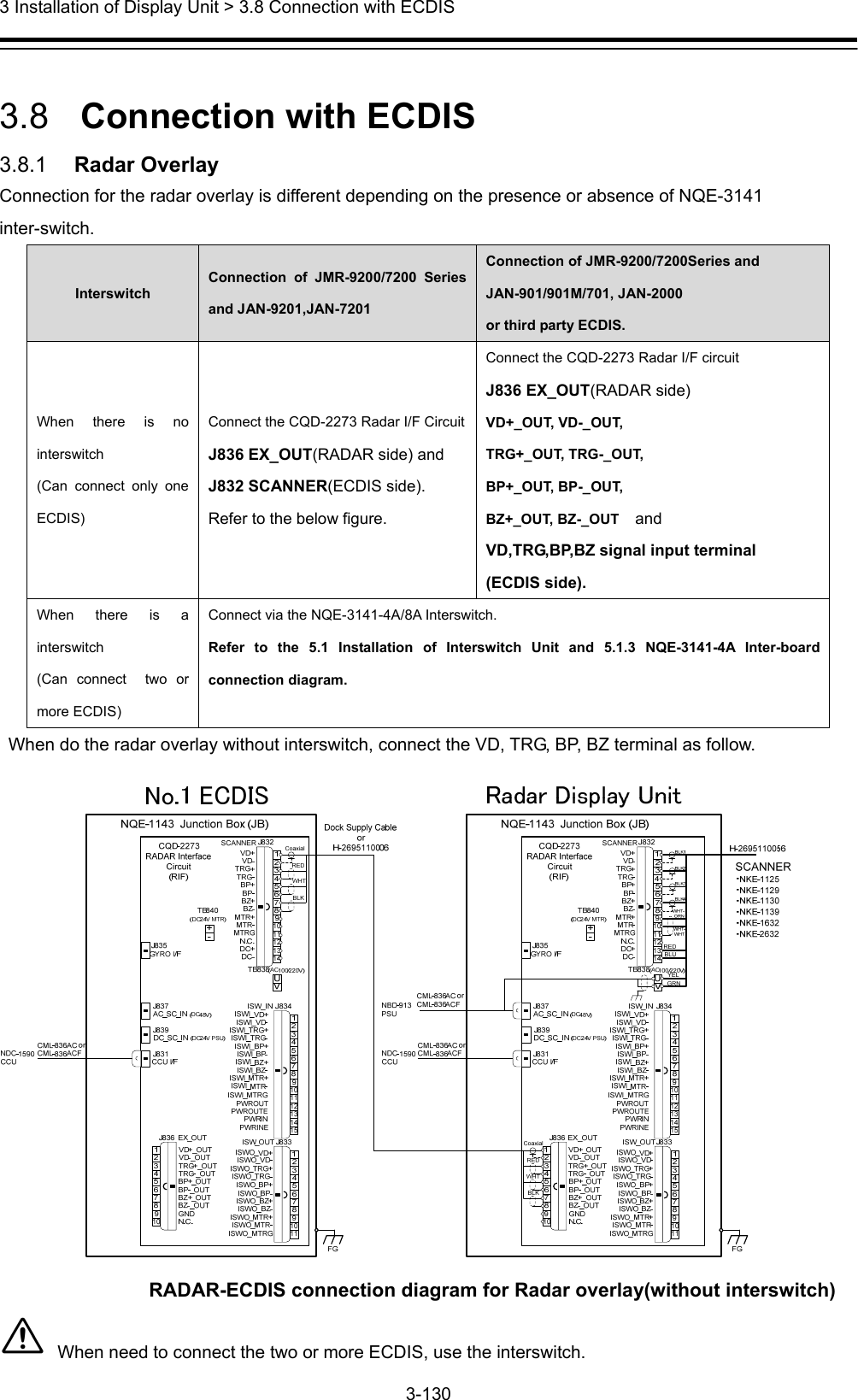
![3 Installation of Display Unit > 3.13 Initialization for the specified model 3-143 Then the following screen is displayed. Make sure that the model name that appears during a restart and model name selected in step 3 matches. Restart by clicking the [RESTART] button. Or restart automatically after 30 seconds. Step4: Checking for the splash screen After restarting, the following dialog is displayed. Confirm that the Model name displayed on the splash screen and the Name Label pasted in step 3 is match. ● When the model name matched, click the [Yes] button. Proceed to the next step. ● When the model name mismatched, click the [No] button. Initialization tool will return to the screen of step3. Please check the equipment information again. The following dialog is displayed. Peel off the Name Label pasted in step 3, and then click the [OK] button.](https://usermanual.wiki/Japan-Radio-Co/NKE2632.Installation-Manual-Part-5/User-Guide-2791038-Page-50.png)
![3 Installation of Display Unit > 3.13 Initialization for the specified model 3-144 Step5: Serial Number The following dialog is displayed. Input the serial number of each unit. And then click the [SET] button. - Please make sure that serial number and manufacturing number indicated are matched. - When setting the desktop type or flush mount type, may not enter the serial number of the monitor. - When input the JB(Junction box) serial number , enter the barcode number and suffix of JB. - May not enter the serial number of SLC, AOC, GIF, RIF, SLC#2. Step6: Software Update Update is started. It takes several ,minutes. Display unit will restart several times during the software update. This is normal behavior.](https://usermanual.wiki/Japan-Radio-Co/NKE2632.Installation-Manual-Part-5/User-Guide-2791038-Page-51.png)
![3 Installation of Display Unit > 3.13 Initialization for the specified model 3-145 Step7: IP Address Set the IP Address by selecting the Unit No. from dropdown list, and then click the [SET] button. Step8: Cleanup The tool deletes unnecessary files automatically.](https://usermanual.wiki/Japan-Radio-Co/NKE2632.Installation-Manual-Part-5/User-Guide-2791038-Page-52.png)
![3 Installation of Display Unit > 3.13 Initialization for the specified model 3-146 Step9: Result Click the [FINISH] button. The resulting CSV file is output. The initialize ends above. [Display the path of the outputted csv file]](https://usermanual.wiki/Japan-Radio-Co/NKE2632.Installation-Manual-Part-5/User-Guide-2791038-Page-53.png)