Japan Radio Co NKE2632 Solid State S-Band Marine Radar User Manual Instruction Manual Funtion Part 4
Japan Radio Co Ltd. Solid State S-Band Marine Radar Instruction Manual Funtion Part 4
Contents
- 1. Installation Manual Part 1
- 2. Installation Manual Part 2
- 3. Installation Manual Part 3
- 4. Installation Manual Part 4
- 5. Installation Manual Part 5
- 6. Installation Manual Part 6
- 7. Installation Manual Part 7
- 8. Installation Manual Part 8
- 9. Installation Manual Part 9
- 10. Installation Manual Part 10
- 11. Installation Manual Part 11
- 12. Instruction Manual Operation Part 1
- 13. Instruction Manual Operation Part 2
- 14. Instruction Manual Operation Part 3
- 15. Instruction Manual Operation Part 4
- 16. Instruction Manual Funtion Part 1
- 17. Instruction Manual Funtion Part 2
- 18. Instruction Manual Funtion Part 3
- 19. Instruction Manual Funtion Part 4
- 20. Instruction Manual Funtion Part 5
- 21. Instruction Manual Funtion Part 6
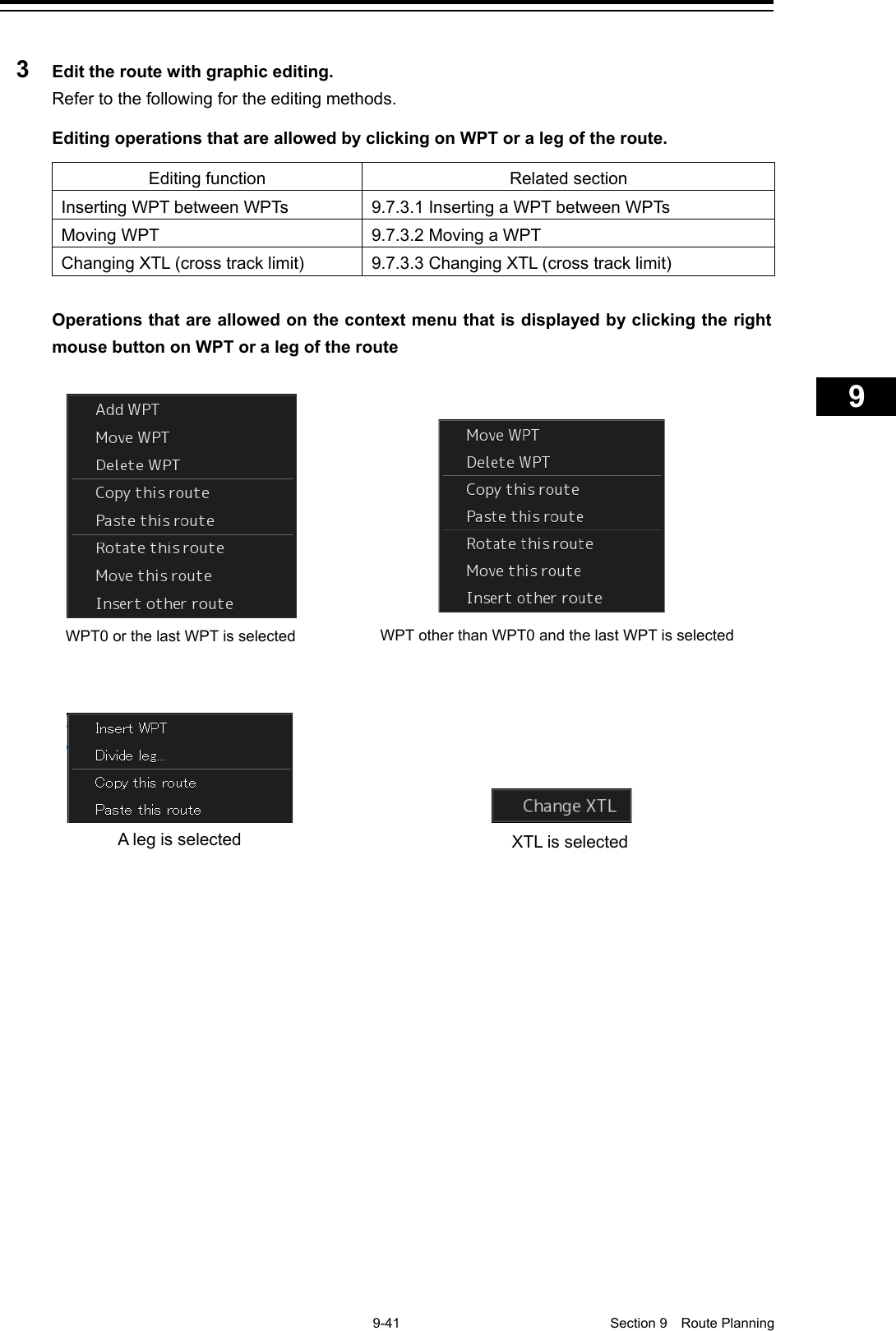
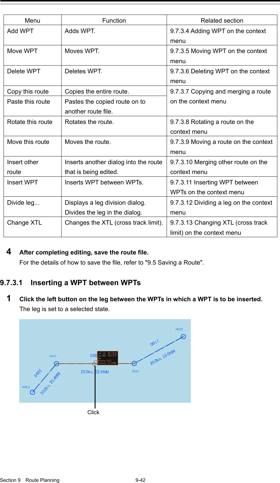
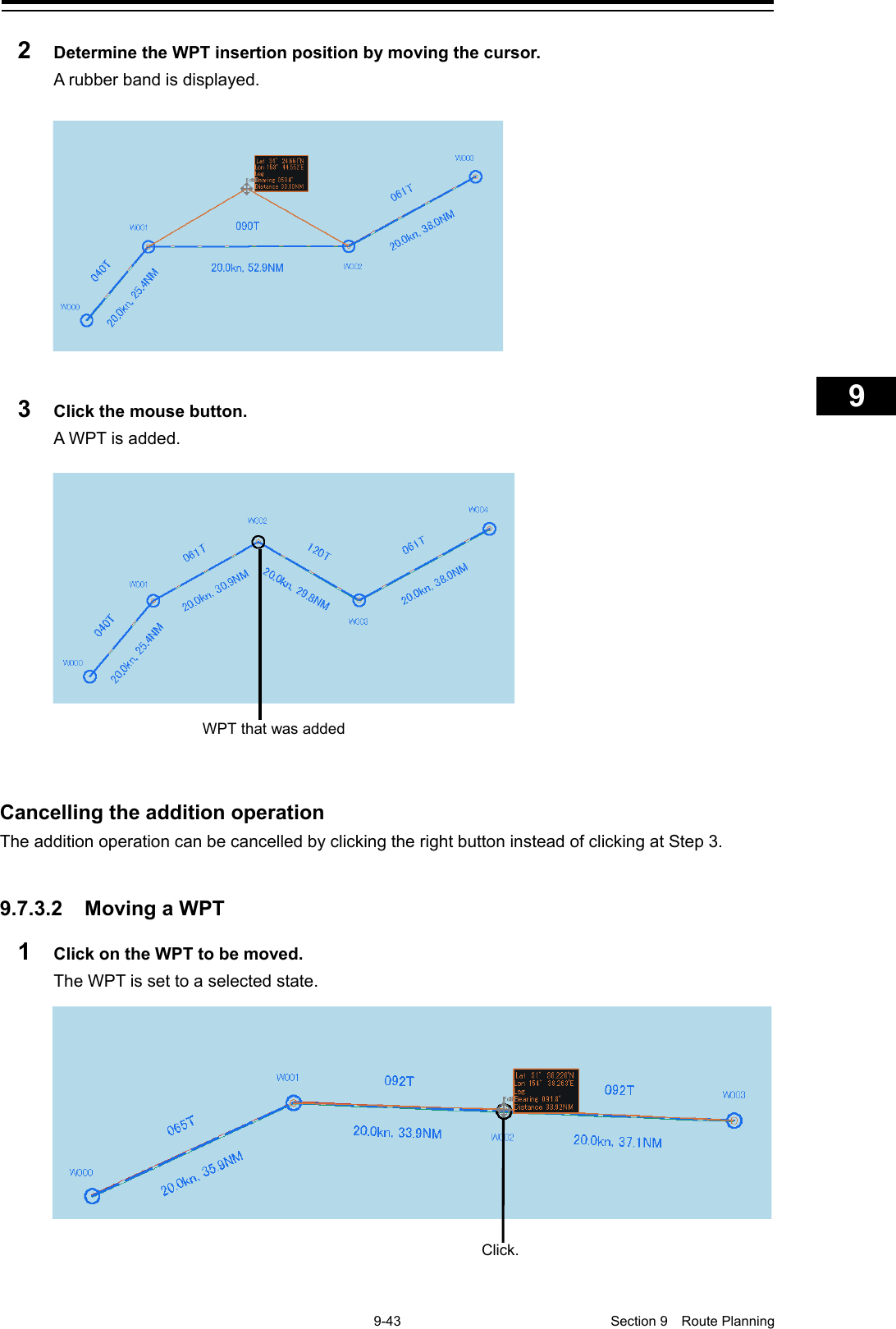
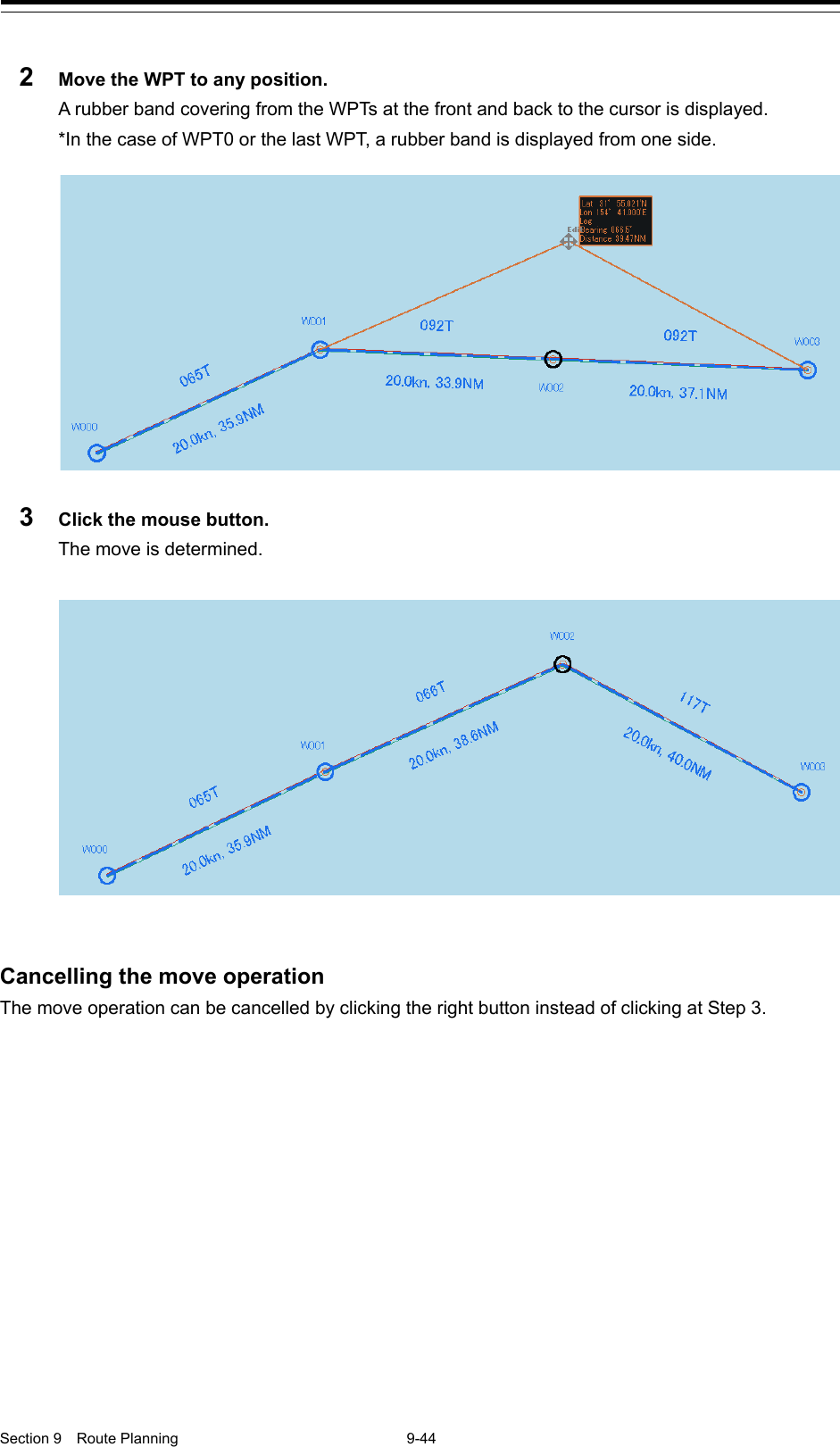
Instruction Manual Funtion Part 4
![Section 9 Route Planning 9-40 5 Add as many WPTs as required in the same way. Memo When Use Assistant circle is not used for creation of the next WPT, clear the item by clicking on [Use Assistant circle]. 6 After creating the last WPT, double click the left button or click the right button. The Route planning is terminated. 9.7.3 Editing a route by graphic editing 1 Click on the [Open] button on the Route Planning bar. Or select the [File operation...] button that is displayed by clicking on the Route Planning menu button. The "File operation..." dialog box appears. 2 Select the route file to be edited and click on the [Open] button. Memo If [Read only] is selected, the file overwrite function is disabled. To overwrite the existing file, clear the item before opening the file.](https://usermanual.wiki/Japan-Radio-Co/NKE2632.Instruction-Manual-Funtion-Part-4/User-Guide-2791063-Page-1.png)
![Section 9 Route Planning 9-46 9.7.3.4 Adding WPT on the context menu Add a WPT to WPT0 or the last WPT. 1 Click the right mouse button on WPT0 or the last WPT. The context menu is displayed. 2 Click [Add WPT] on the context menu. The cursor changes to the WPT addition mode. 3 Move the cursor on the position of the WPT to be added. 4 Click the mouse button. WPT is added. Note In the case of ARCS, when WPT is specified at a position other than the active chart and another panel exists at the positon, the panel display changes automatically. WPT that was added](https://usermanual.wiki/Japan-Radio-Co/NKE2632.Instruction-Manual-Funtion-Part-4/User-Guide-2791063-Page-7.png)
![9-47 Section 9 Route Planning 1 2 3 4 5 6 7 8 9 10 11 12 13 14 15 16 17 18 19 20 21 22 23 24 25 26 27 Cancelling the addition operation The addition operation can be cancelled by clicking the right button instead of clicking at Step 4. 9.7.3.5 Moving WPT on the context menu 1 Click the right button on the WPT to be moved. The context menu is displayed. 2 Click Love WPT] on the context menu. The cursor mode changes to the WPT move mode. 3 Move the cursor to the required position. 4 Click the mouse button. Cancelling the addition operation The addition operation can be cancelled by clicking the right button instead of clicking at Step 4. WPT that was added](https://usermanual.wiki/Japan-Radio-Co/NKE2632.Instruction-Manual-Funtion-Part-4/User-Guide-2791063-Page-8.png)
![Section 9 Route Planning 9-48 9.7.3.6 Deleting WPT on the context menu 1 Click the right button on the WPT to be deleted. The context menu is displayed. 2 Click [Delete WPT] on the context menu. The WPT is deleted.](https://usermanual.wiki/Japan-Radio-Co/NKE2632.Instruction-Manual-Funtion-Part-4/User-Guide-2791063-Page-9.png)
![9-49 Section 9 Route Planning 1 2 3 4 5 6 7 8 9 10 11 12 13 14 15 16 17 18 19 20 21 22 23 24 25 26 27 9.7.3.7 Copying and pasting a route on the context menu A route can be copied and pasted on to another route file. 1 Click the right button on a WPT of the route to be copied. The context menu is displayed. 2 Select [Copy this route] on the context menu. The route is copied. 3 Open the route file of the merge destination by switching the tab. 4 Select the route to be merged and click the right button. 5 Click on [Paste this route] (merging routes) in the context menu. The copied route is merged with the selected route. Selected route Route file that is currently being selected Route file at the merge destination Merged route](https://usermanual.wiki/Japan-Radio-Co/NKE2632.Instruction-Manual-Funtion-Part-4/User-Guide-2791063-Page-10.png)
![Section 9 Route Planning 9-50 Note At pasting, Course, Distance, Total Distance, ROT, TTG, and ETA are recalculated. When a Route planning error occurs as a result, an error message is displayed and insertion and linkage are not performed. For the error messages that are displayed, refer to "9.12 Error Messages that are Displayed when a Route is Created". 9.7.3.8 Rotating a route on the context menu 1 Click the right mouse button on the WPT No. that is used as the reference of rotation. The context menu is displayed. 2 Click [Rotate this route] on the context menu. 3 Rotate the route. The route rotates based on the selected WPT](https://usermanual.wiki/Japan-Radio-Co/NKE2632.Instruction-Manual-Funtion-Part-4/User-Guide-2791063-Page-11.png)
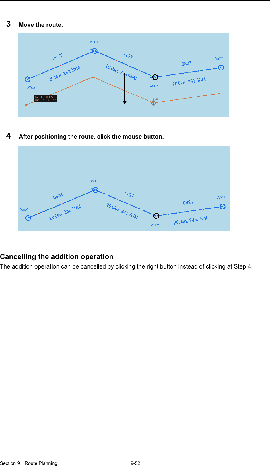
![9-51 Section 9 Route Planning 1 2 3 4 5 6 7 8 9 10 11 12 13 14 15 16 17 18 19 20 21 22 23 24 25 26 27 4 Click the mouse button. Cancelling the addition operation The addition operation can be cancelled by clicking the right button instead of clicking at Step 4. 9.7.3.9 Moving a route on the context menu 1 Click the right mouse button on the WPT of any of the routes to be moved. The context menu is displayed. 2 Click [Move this route] on the context menu.](https://usermanual.wiki/Japan-Radio-Co/NKE2632.Instruction-Manual-Funtion-Part-4/User-Guide-2791063-Page-12.png)
![9-53 Section 9 Route Planning 1 2 3 4 5 6 7 8 9 10 11 12 13 14 15 16 17 18 19 20 21 22 23 24 25 26 27 9.7.3.10 Merging other route on the context menu Merge the route of another file with the last WPT of the route. 1 Click the right mouse button on WPT No. The context menu is displayed. 2 Click on [Insert other route] in the context menu. The "Insert other route" dialog is displayed. 3 Click on the route file to be merged from the [Select Route] combo box. 4 Click on the [OK] button. The route file is merged. Note When the range exceeded the insertion allowed range, an error message is displayed and the route will not be inserted. Merged route](https://usermanual.wiki/Japan-Radio-Co/NKE2632.Instruction-Manual-Funtion-Part-4/User-Guide-2791063-Page-14.png)
![Section 9 Route Planning 9-54 9.7.3.11 Inserting WPT between WPTs on the context menu 1 Click the right mouse button on the leg between the WPTs within which WPT is to be inserted. The context menu is displayed. 2 Click [Insert WPT] on the context menu. The cursor mode changes to the WPT insertion mode. 3 Move the cursor to the position in which WPT is to be inserted. 4 Click the mouse button. WPT is inserted. Cancelling the insertion operation The insertion operation can be cancelled by clicking the right button instead of clicking at Step 4.](https://usermanual.wiki/Japan-Radio-Co/NKE2632.Instruction-Manual-Funtion-Part-4/User-Guide-2791063-Page-15.png)
![9-55 Section 9 Route Planning 1 2 3 4 5 6 7 8 9 10 11 12 13 14 15 16 17 18 19 20 21 22 23 24 25 26 27 9.7.3.12 Dividing a leg on the context menu 1 Click the right mouse button on the leg of the route to be divided. The context menu is displayed. 2 Click [Divide leg...] on the context menu. The "Divide Route" dialog box appears. 3 Input a division interval. [Every(LON)] (longitude division) 1) Click on "Every(LON)". 2) Enter a longitude division interval. [Every(NM)] (nautical mile division) 1) Click on "Every(NM)". 2) Enter a nautical mile division interval. 4 Click on the [OK] button. The leg that was selected in Step 1 is divided in the unit specified in Step 3.](https://usermanual.wiki/Japan-Radio-Co/NKE2632.Instruction-Manual-Funtion-Part-4/User-Guide-2791063-Page-16.png)
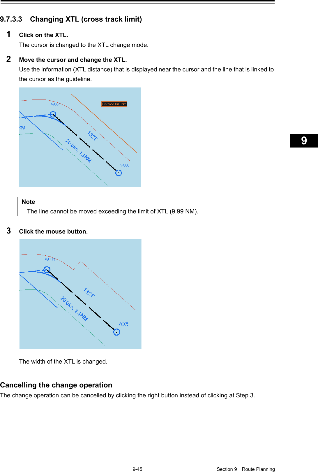
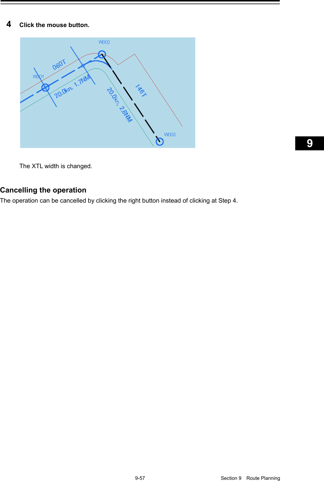
![Section 9 Route Planning 9-56 Note When the total number of WPTs exceeds the maximum value of 511 as a result of leg division, leg division is executed within the range that does not exceed 511 in the entire course. 9.7.3.13 Changing XTL (cross track limit) on the context menu 1 Click the right mouse button on XTL. The context menu is displayed. 2 Click [Change XTL] on the context menu. 3 Change the width of XTL by moving the cursor.](https://usermanual.wiki/Japan-Radio-Co/NKE2632.Instruction-Manual-Funtion-Part-4/User-Guide-2791063-Page-17.png)
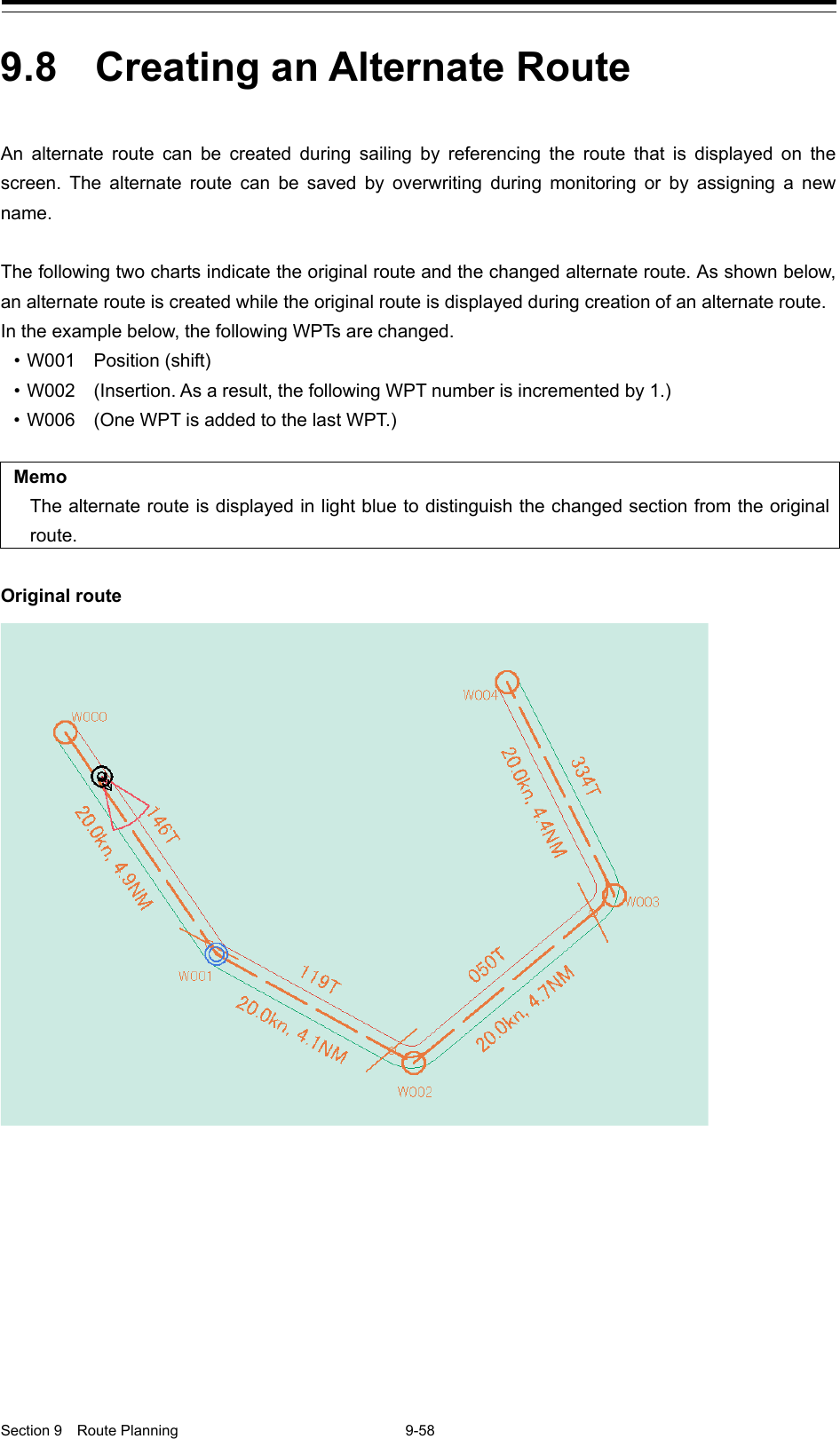
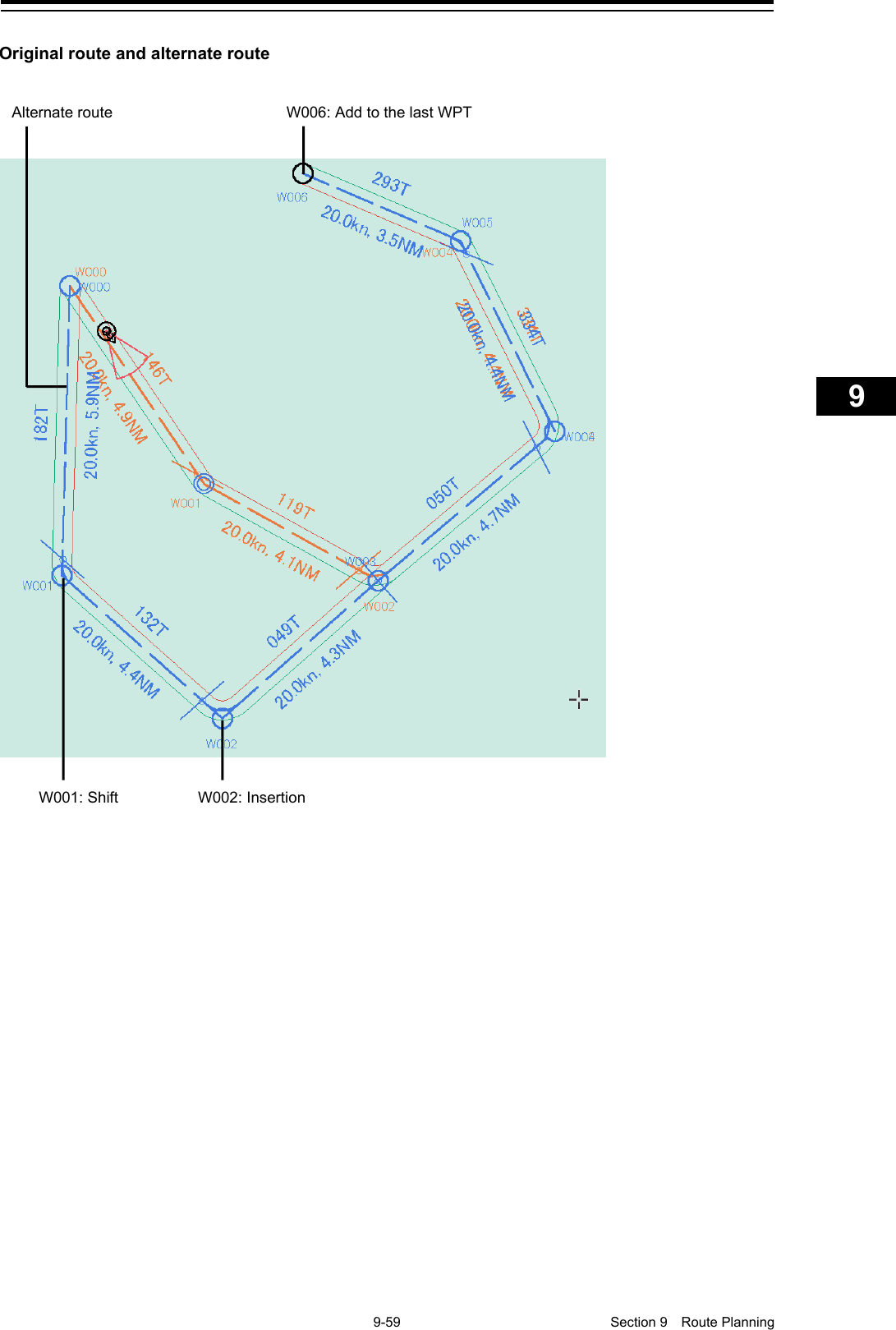
![Section 9 Route Planning 9-60 9.8.1 Creating an alternate route 1 Click the right mouse button on the WPT or leg of the route that is being monitored. The context menu is displayed. 2 Click on [Monitoring WPT xxx] or [Monitoring LEG xxx] of the context menu. The context menu is displayed. 3 Click on [Edit this route] of the context menu. The “Route Planning” dialog is displayed.](https://usermanual.wiki/Japan-Radio-Co/NKE2632.Instruction-Manual-Funtion-Part-4/User-Guide-2791063-Page-21.png)
![9-61 Section 9 Route Planning 1 2 3 4 5 6 7 8 9 10 11 12 13 14 15 16 17 18 19 20 21 22 23 24 25 26 27 4 For table editing, edit the route by using the same procedure as that from Step 3 of “9.6.4 Editing a route by table editing”. 5 For graphic editing, click the right mouse button on the WPT or leg of the route that is being monitored. The context menu is displayed. 6 Click on [Planning WPT] or [Planning LEG] of the context menu. The context menu for editing WPT or leg is displayed. 7 Edit the route by using the same procedure as from Step 3 of “9.7.3 Editing a route by using graphic editing”. 9.8.2 Saving an alternate route 9.8.2.1 Overwriting without changing the file name 1 Click on the [Save] button. A confirmation dialog is displayed. 2 Click on the [YES] button. The alternate route is displayed and used instead of the original route.](https://usermanual.wiki/Japan-Radio-Co/NKE2632.Instruction-Manual-Funtion-Part-4/User-Guide-2791063-Page-22.png)
![Section 9 Route Planning 9-62 Note In this case, the route name that is currently monitored remains unchanged. The original route file no longer exists since it is overwritten. 9.8.2.2 Saving the file by naming 1 Click on the [Save as] button on the route plan menu of the route plan bar. The “Save as Route File” dialog is displayed. 2 Enter a new file name and click on the [Save] button. The alternate route is displayed and used instead of the original route. Note In this case, the route name that is being monitored is changed to the file name that was entered. The original route file remains.](https://usermanual.wiki/Japan-Radio-Co/NKE2632.Instruction-Manual-Funtion-Part-4/User-Guide-2791063-Page-23.png)
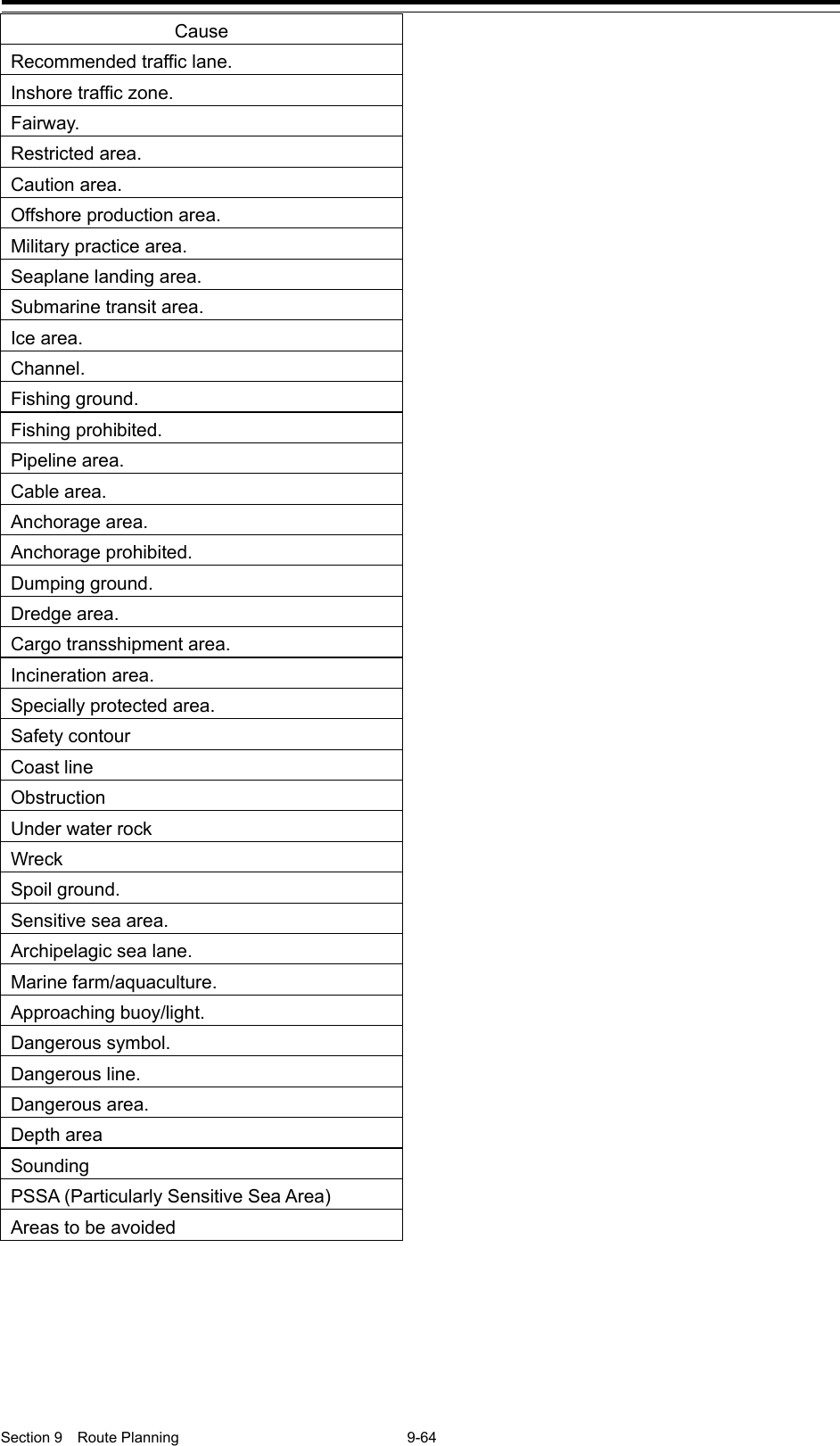
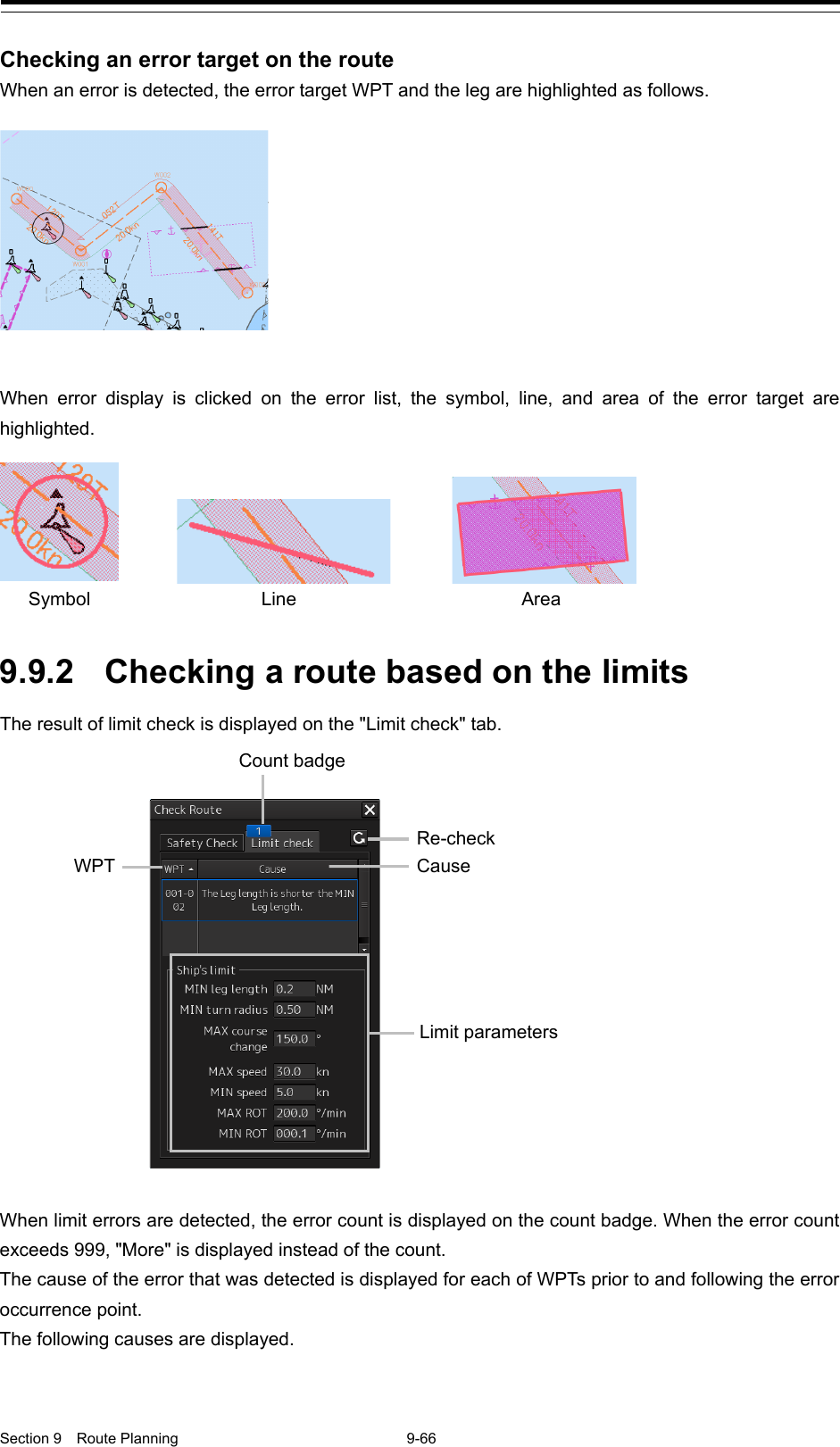
![9-63 Section 9 Route Planning 1 2 3 4 5 6 7 8 9 10 11 12 13 14 15 16 17 18 19 20 21 22 23 24 25 26 27 9.9 Checking Route Data Route data is constantly checked based on the safety standards and limits. These items are checked on the "Check Route" dialog box. The "Check Route" dialog box appears by clicking on the [Show Route Check] button on the Route Planning bar. 9.9.1 Checking a route based on the safety standards The result of safety check is displayed on the "Safety check" tab. When safety errors are detected, the number of errors is displayed on the count badge. When the error count exceeds 999, "More" is displayed instead of the count. The list of Cause and Result of the errors that were detected is displayed for each WPT prior to and following the error occurrence point. The following causes are displayed. Cause Traffic separation zone. Traffic crossing. Traffic roundabout. Traffic precautionary. Two way traffic. Deeper water route. Approval status (Result) Re-check button WPT Check box Count badge Cause [Safety contour] box [Jump] button [Reset] button [Disregard] button](https://usermanual.wiki/Japan-Radio-Co/NKE2632.Instruction-Manual-Funtion-Part-4/User-Guide-2791063-Page-24.png)
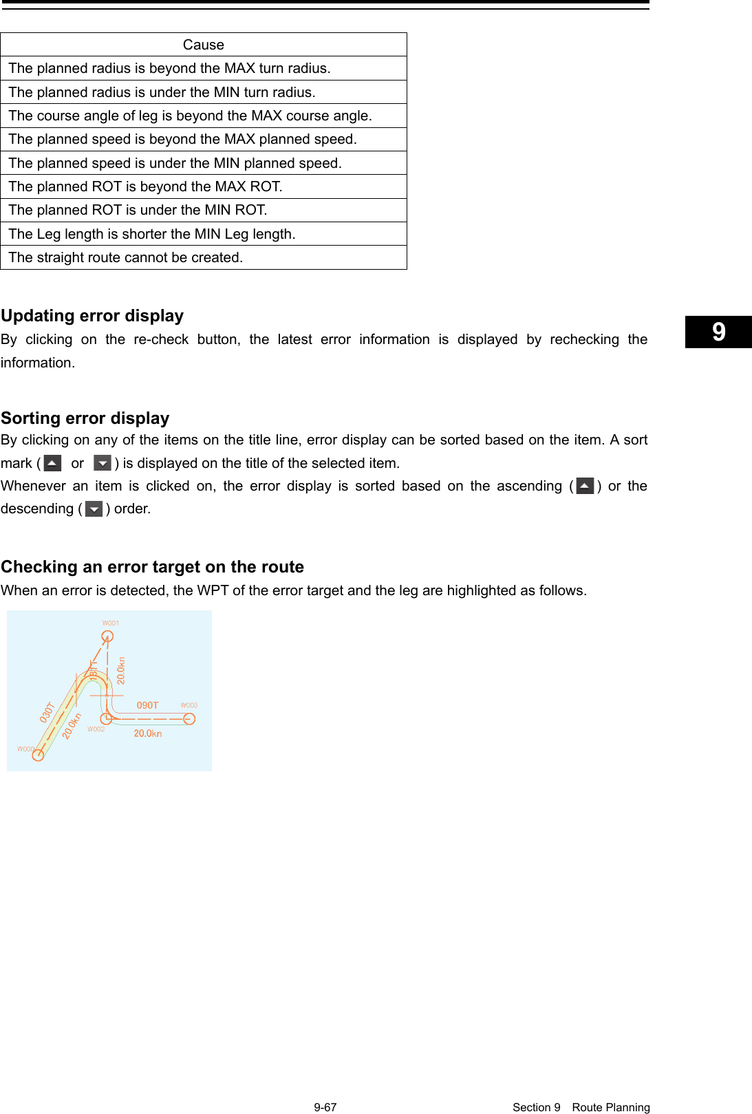
![9-65 Section 9 Route Planning 1 2 3 4 5 6 7 8 9 10 11 12 13 14 15 16 17 18 19 20 21 22 23 24 25 26 27 Updating an error list By clicking on the Re-check button, the latest error information is displayed by rechecking the information. Sorting error display By clicking on any of the items on the title line, error display can be sorted based on the item. A sort mark ( or ) is displayed on the title of the selected item. Whenever an item is clicked on, the error display is sorted based on the ascending ( ) or the descending ( ) order. Selecting an error to be processed Select the check box of the error to be processed. To select all the errors, select the check box on the title line. When the [Jump] button is clicked on, control jumps to the occurrence point of the error that was selected on the error list. Ignoring an error Click on the [Disregard] button. To restore the error that was once ignored, click on the [Reset] button. Checking an error target on the list When an error is detected, the WPT under which the error occurred is highlighted in red.](https://usermanual.wiki/Japan-Radio-Co/NKE2632.Instruction-Manual-Funtion-Part-4/User-Guide-2791063-Page-26.png)
![Section 9 Route Planning 9-68 9.10 Navigation Calculation Function This section describes the function that supports the distance and bearing calculation that are required for navigation. 9.10.1 ROT (Rate of Turn) ROT is automatically calculated from the planned ship’s speed and the turn radius and displayed on [ROT]. 9.10.2 ETA (Estimated Time of Arrival) ETA is automatically calculated from the WPT position, planned ship’s speed, and time zone and is displayed on [ETA]. 9.10.3 TTG (Time to Go) TTG is automatically calculated from the WPT position and planned ship’s speed and displayed on [TTG]. A display format can be selected from the list that is displayed by clicking on the TTG title. 01Days 23:599999:59[Days hh:mm] [hhhh:mm]](https://usermanual.wiki/Japan-Radio-Co/NKE2632.Instruction-Manual-Funtion-Part-4/User-Guide-2791063-Page-29.png)
![9-69 Section 9 Route Planning 1 2 3 4 5 6 7 8 9 10 11 12 13 14 15 16 17 18 19 20 21 22 23 24 25 26 27 9.11 Importing/Exporting a Route File By using the "Import" or "Export" dialog box, the route file that was created can be imported/exported. The dialog box can be displayed as follows. 1 Click on the Route Planning menu button. 2 Select [Import] or [Export] from the list that is displayed. The "Import" or "Export" dialog box appears. 9.11.1 Importing a route file 1 Specify the "Drive", the "Folder", the "File name", and the "File Type" that stores the file to be imported. 2 Click on the [OK] button. The route file that is selected can be imported. Press the [X] button to cancel the importing of a file. Note The file type of the file to be imported can be selected in the [File Type] combo box.The file types that can be imported are as follows. .rtn: Displays a route file (normal). This file is used for ECDIS (JAN-701B/901B) and Chart Radar (JMA-900B) .rta: Displays a route file (TCS route). This file is used for ECDIS (JAN-701B/901B) and Chart Radar (JMA-900B) .rtm: Displays a route file used in this equipment. .csv: Displayes a route file in CSV format. *(Wildcard): Displays all the files that can be imported.](https://usermanual.wiki/Japan-Radio-Co/NKE2632.Instruction-Manual-Funtion-Part-4/User-Guide-2791063-Page-30.png)
![Section 9 Route Planning 9-70 9.11.2 Exporting a route file 1 Specify the "Drive", the "Folder", the "File name", and the "File Type" that stores the file to be exported. 2 Click on the [OK] button. The route file that is currently opened is exported. Press the [X] button to cancel the exporting of a file.](https://usermanual.wiki/Japan-Radio-Co/NKE2632.Instruction-Manual-Funtion-Part-4/User-Guide-2791063-Page-31.png)

![10-1 Section 10 Route Monitoring 1 2 3 4 5 6 7 8 9 10 11 12 13 14 15 16 17 18 19 20 21 22 23 24 25 26 27 Section 10 Route Monitoring 10.1 Route Monitoring The route monitoring function enables monitoring of the position of own ship, heading, and ship speed, and calculation of an expected time of arrival using the route created in route planning. Memo For moitoring a route, it is necessary to create a route file or copy a route file in route planning in advance. For the details of route planning, refer to "Section 9 Route Planning". 10.1.1 Starting route monitoring 1 Click on the [Menu] button on the left toolbar. The menu is displayed. 2 Click on the [Route Monitoring] button on the menu. The "Route Monitoring" dialog box appears. 3 Select a required route file. [Selecting from the [Route] combo box] 1) Click on the [Route] combo box. 2) Select a required route. [Selecting from a route file list] 1) Click on the "File operation" dialog box display button. 2) Select a required file from the list of the "File operation" dialog box. About the "File operation" dialog box, refer to "10.2 Selecting and Deleting Route Files" 3) Click on the [Open] button. "File operation" dialog box display button](https://usermanual.wiki/Japan-Radio-Co/NKE2632.Instruction-Manual-Funtion-Part-4/User-Guide-2791063-Page-34.png)
![Section 10 Route Monitoring 10-2 4 Select a WPT to which the ship is to travel. A WPT can be selected automatically or manually. [Automatic selection] The nearest WPT from the own ship’s position is selected automatically. 1) Open the next WPT list by clicking on the [To W PT ] combo box. 2) Select [AUTO Select]. [Manual selection] Select a WPT manually. 1) Open the next WPT list by clicking on the [To W PT ] combo box. 2) Click on a required WPT. Memo When route sharing with GPS is enabled, [Active Route] is displayed on [Route] combo box. To start route monitoring by using the route that has been created by GPS, select [Active Route]. 10.1.2 Ending route monitoring 1 Click on the [Menu] button on the left toolbar. The menu is displayed. 2 Click on the [Route Monitoring] button on the menu. The "Route Monitoring" dialog box appears. 3 Click on the [Route] combo box. 4 Click on [UNLOAD].](https://usermanual.wiki/Japan-Radio-Co/NKE2632.Instruction-Manual-Funtion-Part-4/User-Guide-2791063-Page-35.png)
![10-3 Section 10 Route Monitoring 1 2 3 4 5 6 7 8 9 10 11 12 13 14 15 16 17 18 19 20 21 22 23 24 25 26 27 10.2 Selecting and Deleting Route Files Selection of the route to be displayed and deletion of obsolete route files are enabled on the "File operation" dialog box. Use the following procedure to open the "File Operation" dialog box. 1 Click on the [Menu] button on the left toolbar. The menu is displayed. 2 Click on the [Route Monitoring] button on the menu. The "Route Monitoring" dialog box appears. 3 Click on the [File operation] dialog box display button. The "File Operation" dialog box appears. 10.2.1 Selecting a route to be displayed 1 Select the selection check box of the route file to be displayed. When [Name] is clicked on, is displayed. Whenever is clicked on, the file display sequence changes to the ascending/descending sequence based on the names. 2 Click on the [Open] button. Selection check File name Comment File creation date](https://usermanual.wiki/Japan-Radio-Co/NKE2632.Instruction-Manual-Funtion-Part-4/User-Guide-2791063-Page-36.png)
![Section 10 Route Monitoring 10-4 10.2.2 Deleting a route file 1 Click the selection check of the route file to be deleted. 2 Click on the [Delete] button. A message dialog box is displayed as to whether the deletion is to be executed. 3 When executing deletion, click on the [Yes] button. To cancel deletion, click on the [No] button. Note The file of the route that is currently monitored or the route that is used for automatic sailing cannot be deleted. The following message dialog box appears. Close the dialog box by clicking on the [OK] button.](https://usermanual.wiki/Japan-Radio-Co/NKE2632.Instruction-Manual-Funtion-Part-4/User-Guide-2791063-Page-37.png)
![10-5 Section 10 Route Monitoring 1 2 3 4 5 6 7 8 9 10 11 12 13 14 15 16 17 18 19 20 21 22 23 24 25 26 27 10.3 Voyage Information (Voyage Monitoring Information) Dialog Box The "Voyage Information" (voyage monitoring information) dialog box is used to monitor voyage statuses. In addition to voyage monitoring, execution of course change and termination of automatic navigation can also be performed. Use the following procedure to open the "Voyage Information" dialog box. 1 Click on the [Menu] button on the left toolbar. The menu is displayed. 2 Click on the [Route Monitoring] button on the menu. The "Route Monitoring" dialog box appears. 3 Click on the [Voyage Information] button. The "Voyage Information" dialog box appears. [1] Route name display A file name of the route that is being monitored is displayed. [2] [3] [4] [5] [1] [6]](https://usermanual.wiki/Japan-Radio-Co/NKE2632.Instruction-Manual-Funtion-Part-4/User-Guide-2791063-Page-38.png)
![Section 10 Route Monitoring 10-6 [2] To WPT information The To WPT information that was selected in the “Route Monitoring” dialog box is displayed. [a] [To WPT] (To WPT number) Displays a To WP T number. [b] [Distance] (Own ship - To WPT distance) Displays a distance between the position of the own ship and the position indicated by To WPT. [c] [Bearing] (Own ship - To WPT angle) Displays an angle of the own ship and the position indicated by To WPT. [d] [TTG] (Expected traveling time) Displays an expected traveling time to reach the position indicated by To WPT. [e] [ETA] (Expected time of arrival) Displays the expected time of arrival at the position indicated by To W PT. [f] Cross track direction Displays a cross track direction of the own ship. When the own ship is cross-tracked on the right side, [STBD] is displayed and when the own ship is cross-tracked on the left side, [PORT] is displayed. [g] Cross track distance Displays a cross track distance of the own ship. [h] Cross track distance unit switching button Switches the display unit of a cross track distance. Whenever the button is clicked on, the unit is switched to "m" or "NM". [a] [b] [c] [d] [e] [f] [g] [h]](https://usermanual.wiki/Japan-Radio-Co/NKE2632.Instruction-Manual-Funtion-Part-4/User-Guide-2791063-Page-39.png)
![10-7 Section 10 Route Monitoring 1 2 3 4 5 6 7 8 9 10 11 12 13 14 15 16 17 18 19 20 21 22 23 24 25 26 27 [3] Next WPT information [a] [Next WPT] (Next WPT number) Displays a Next WPT number. [b] [New Course] (Leg bearing of Next WPT) Displays a leg bearing of the Next WPT. [4] [Final ETA/Total Distance] (Expected time of arrival at final WPT/total distance) This section displays the expected time of arrival at the final WPT based on the calculation from the current speed and the distance from WPT0 (departure point) to the position of the own ship. The expected time of arrival at the final WPT and the total distance can be displayed or hidden by clicking on the Open/Close button. [a] [Final ETA] Displays ETA up to the last WPT that was calculated based on the current ship’s speed. [b] [Total Distance (from WPT0)] (Total distance) Displays a total distance from WPT0 to the own ship. [a] [b] Open/Close button [a] [b]](https://usermanual.wiki/Japan-Radio-Co/NKE2632.Instruction-Manual-Funtion-Part-4/User-Guide-2791063-Page-40.png)
![Section 10 Route Monitoring 10-8 [5] Automatic sailing information This section displays the status of Auto Pilot that is installed. Note If the Auto Pilot device is not installed, information is not displayed. [a] Automatic sailing status Displays an automatic sailing status. Display Status No display A/P (Auto Pilot) non-connection setting or automatic sailing alert is occurring Track Control The A/P steering mode is set to Track Control. Heading Control The A/P steering mode is set to Heading Control. Manual The A/P steering mode is set to Manual. [b] Control mode Displays a control mode of automatic sailing. Display Status No display Automatic sailing inactive KEEP Automatic sailing/maintaining the course TURN Automatic sailing/turning (TCS category C) Assisted Turn Automatic sailing/turning (TCS category B) [c] Turning mode Displays a turning mode of automatic sailing. Display Status No display Automatic sailing inactive AUTO Automatic turning mode [d] Set heading Displays the set heading to be transmitted to Auto Pilot. [c] [a] [b] [d]](https://usermanual.wiki/Japan-Radio-Co/NKE2632.Instruction-Manual-Funtion-Part-4/User-Guide-2791063-Page-41.png)
![10-9 Section 10 Route Monitoring 1 2 3 4 5 6 7 8 9 10 11 12 13 14 15 16 17 18 19 20 21 22 23 24 25 26 27 [6] [Auto Sail Stop] button Click on this button to terminate automatic sailing. The following message dialog box appears. When the [OK] button is clicked on, automatic sailing terminates. Memo When a message dialog box indicating the switching of the Auto Pilot mode to the Manual mode is displayed, switch the Auto Pilot steering mode to the Manual mode.](https://usermanual.wiki/Japan-Radio-Co/NKE2632.Instruction-Manual-Funtion-Part-4/User-Guide-2791063-Page-42.png)
![Section 10 Route Monitoring 10-10 10.4 Voyage Calculation Dialog Box The "Voyage calculation" dialog box is used to calculate the expected WPT arrival time, the time required, and required ship speed It is also possible to calculate a distance between two points such as between WPTs, from the own ship’s position to WPT, or any position on the route to WPT. Use the following procedure to open the "Voyage calculation" dialog box. 1 Click on the [Menu] button on the left toolbar. The menu is displayed. 2 Click on the [Route Monitoring] button on the menu. The "Route Monitoring" dialog box appears. 3 Click on the [Voyage calculation] button. The "Voyage calculation" dialog box appears.](https://usermanual.wiki/Japan-Radio-Co/NKE2632.Instruction-Manual-Funtion-Part-4/User-Guide-2791063-Page-43.png)
![10-11 Section 10 Route Monitoring 1 2 3 4 5 6 7 8 9 10 11 12 13 14 15 16 17 18 19 20 21 22 23 24 25 26 27 When the [Schedule] (schedule calculation) button is clicked on, a schedule calculation dialog is displayed. When the [Distance] (distance calculation) button is clicked on, a distance calculation dialog is displayed. "Schedule" Dialog [1] [Destined WPT] combo box Select a destined WPT. [2] [Distance] (Distance up to the destined WPT) Displays a distance from the own ship’s position to the selected W PT. [3] [TTG] (Expected traveling time) Displays a traveling time required based on the position from the current SOG value to the destined WP T. [4] [ETA] (Expeced time of arrival) Displays a time at arrival of the destined WPT from the current SOG value. [5] [Calculation] (Calculation) Selects a calculation method and enters the values. "Schedule" Dialog "Distance" Dialog [1] [2] [3] [4] [5] [1] [2] [3]](https://usermanual.wiki/Japan-Radio-Co/NKE2632.Instruction-Manual-Funtion-Part-4/User-Guide-2791063-Page-44.png)
![Section 10 Route Monitoring 10-12 "Distance" Dialog [1] [From] Selects a starting point calculation method and enters the values. [2] [To] Selects an ending point calculation method and enters the values. [3] [Distance (Result)] (Distance calculation result) Displays distance from the starting point and ending point that were obtained from the setting. 10.4.1 Calculating a schedule 1 Click on the [Schedule] button. 2 Click on the [Destined WPT] combo box. 3 Click on the WPT number whose schedule is to be calculated. The measured distance from the own ship to the selected WPT, the estimated required time calculated based on the SOG (Speed Over the Ground), and the estimated time of arrival are displayed.](https://usermanual.wiki/Japan-Radio-Co/NKE2632.Instruction-Manual-Funtion-Part-4/User-Guide-2791063-Page-45.png)
![10-13 Section 10 Route Monitoring 1 2 3 4 5 6 7 8 9 10 11 12 13 14 15 16 17 18 19 20 21 22 23 24 25 26 27 4 Select a calculation method and enter a value. When [Average Speed] (calculated ship’s speed), [TTG] (calculated traveling time), or [ETA] (calculated time of arrival) is selected and a value is entered, the calculation result of the ship’s speed, expected traveling time, and expected time of arrival are displayed. These three items are displayed by linking. [Average Speed]: Enter a ship’s speed. [TTG]: Enter a calculated traveling time. [ETA]: Enter a calculated time of arrival by using a calendar/time picker. 10.4.2 Calculating a distance 1 Click on the [Distance] button.](https://usermanual.wiki/Japan-Radio-Co/NKE2632.Instruction-Manual-Funtion-Part-4/User-Guide-2791063-Page-46.png)
![Section 10 Route Monitoring 10-14 2 Select starting point calculation method and enter a value. Set a starting point for distance calculation by selecting [WPT] (selection of starting WPT), [Pick on the route] (selecting any position on the starting route), or [Ship’s position] (selection of the own ship’s position). [WPT]: Click on a WPT used as the starting point from the combo box. [Pick on the route]: Any position on the routes set in the starting WPT and the end WPT is used as the starting point. When the [Edit] (editing any position) button is clicked, the color of the selectable route changes to green. When any position is clicked, that position becomes the starting point. [Ship’s position]: The own ship’s position is used as the starting point. Click on the WPT to be passed through from the [Via WPT] combo box. 3 Select an ending point calculation method and enter a value. Set an ending point for distance calculation by selecting [WPT] (selection of ending WPT) or [Pick on the route] (selecting any position on the ending route). [WPT]: Click on a WPT used as the ending point from the combo box. [Pick on the route]: Any position on the routes set in the starting WPT and the end WPT is used as the end point. When the [Edit] (editing any position) button is clicked, the color of the selectable route changes to green. When any position is clicked, that position becomes the end point. Memo When the [Edit] button is clicked on, the following message dialog box appears. Position selection can be cancelled by clicking on the [Cancel] button.](https://usermanual.wiki/Japan-Radio-Co/NKE2632.Instruction-Manual-Funtion-Part-4/User-Guide-2791063-Page-47.png)
![10-15 Section 10 Route Monitoring 1 2 3 4 5 6 7 8 9 10 11 12 13 14 15 16 17 18 19 20 21 22 23 24 25 26 27 10.4.3 Example of distance calculation Calculating with [WPT] Selecting [Pick on the route] (Selecting any starting point on the route) as the starting point: Selected segment Route distance between selected WPTs Selected segment Route distance between selected WPTs Set any position on the route as the starting point](https://usermanual.wiki/Japan-Radio-Co/NKE2632.Instruction-Manual-Funtion-Part-4/User-Guide-2791063-Page-48.png)
![Section 10 Route Monitoring 10-16 Selecting [Ship’s position] (Selecting the own ship’s starting position): Selected segment WPT Route distance between selected WPTs Own ship's position](https://usermanual.wiki/Japan-Radio-Co/NKE2632.Instruction-Manual-Funtion-Part-4/User-Guide-2791063-Page-49.png)