Japan Radio Co NKE2632 Solid State S-Band Marine Radar User Manual Installation Manual Part 4
Japan Radio Co Ltd. Solid State S-Band Marine Radar Installation Manual Part 4
Contents
- 1. Installation Manual Part 1
- 2. Installation Manual Part 2
- 3. Installation Manual Part 3
- 4. Installation Manual Part 4
- 5. Installation Manual Part 5
- 6. Installation Manual Part 6
- 7. Installation Manual Part 7
- 8. Installation Manual Part 8
- 9. Installation Manual Part 9
- 10. Installation Manual Part 10
- 11. Installation Manual Part 11
- 12. Instruction Manual Operation Part 1
- 13. Instruction Manual Operation Part 2
- 14. Instruction Manual Operation Part 3
- 15. Instruction Manual Operation Part 4
- 16. Instruction Manual Funtion Part 1
- 17. Instruction Manual Funtion Part 2
- 18. Instruction Manual Funtion Part 3
- 19. Instruction Manual Funtion Part 4
- 20. Instruction Manual Funtion Part 5
- 21. Instruction Manual Funtion Part 6
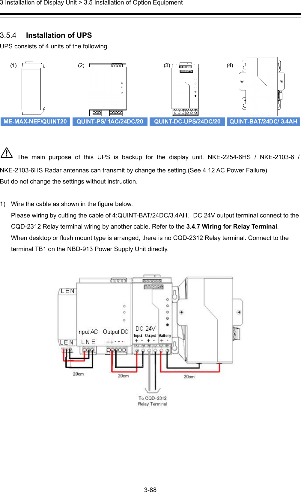
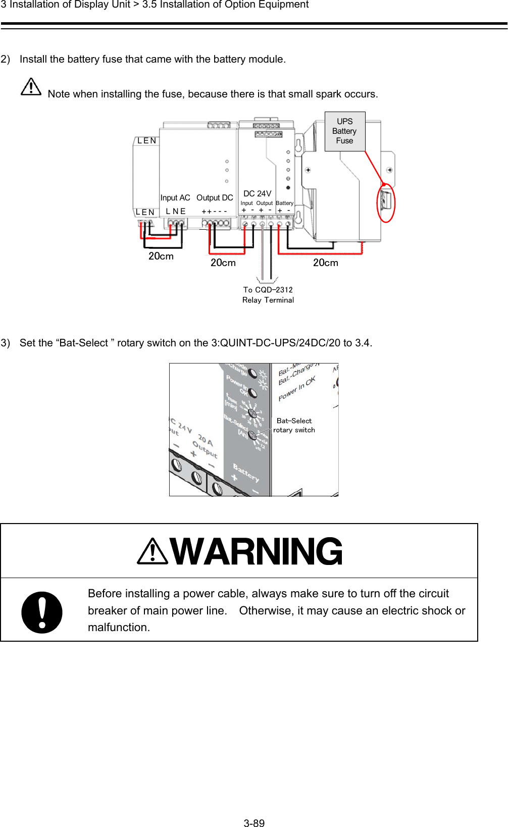
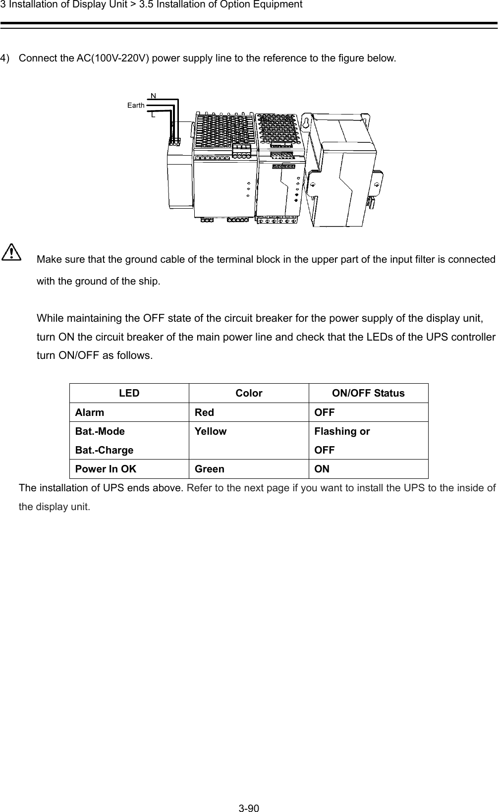
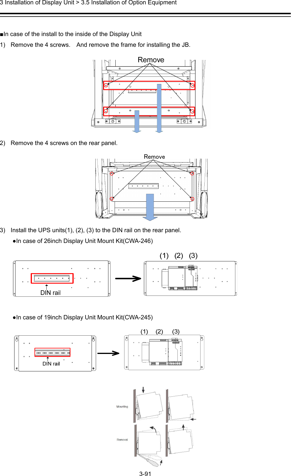
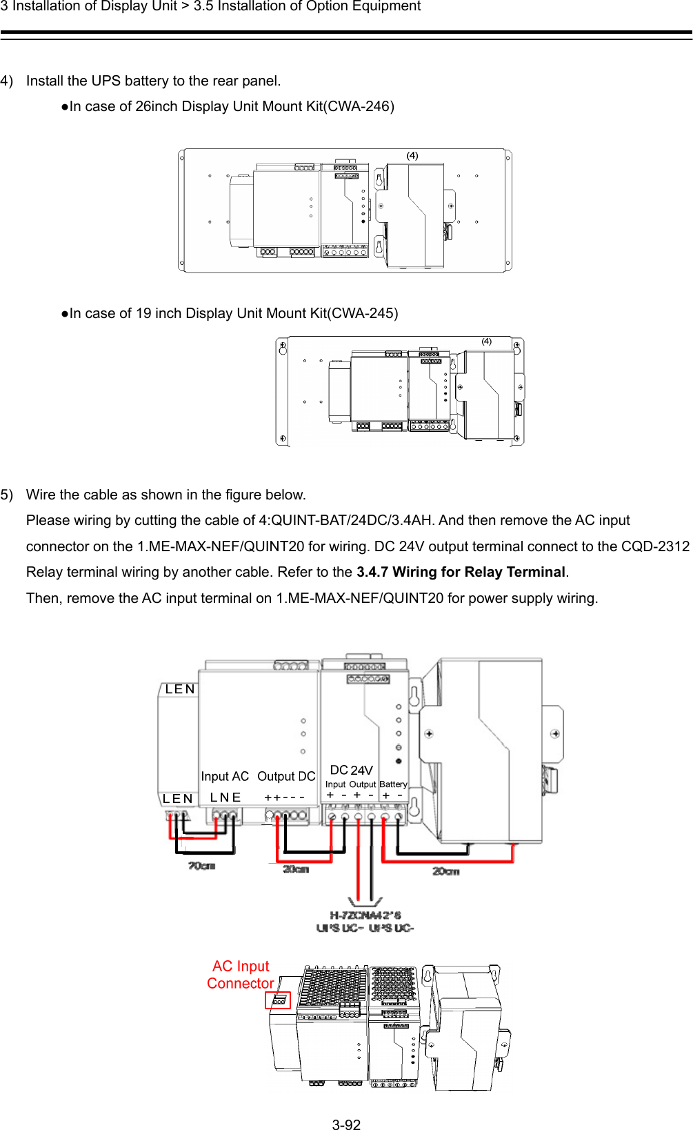
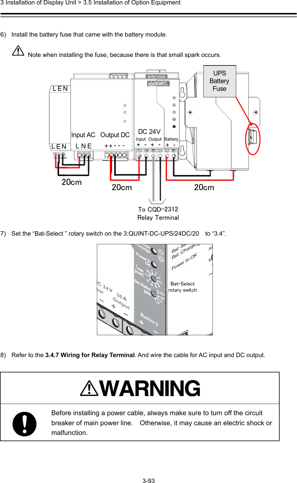
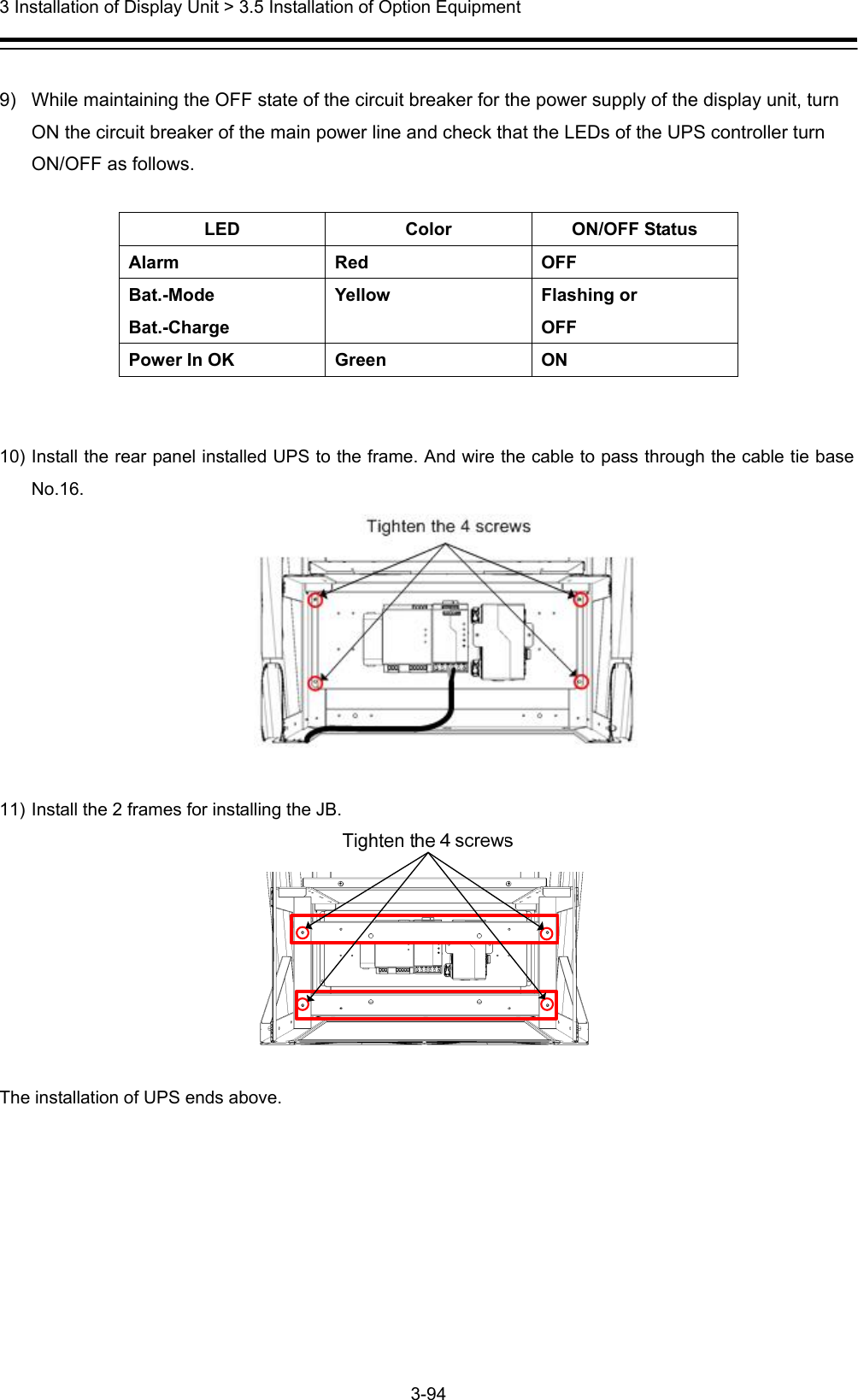
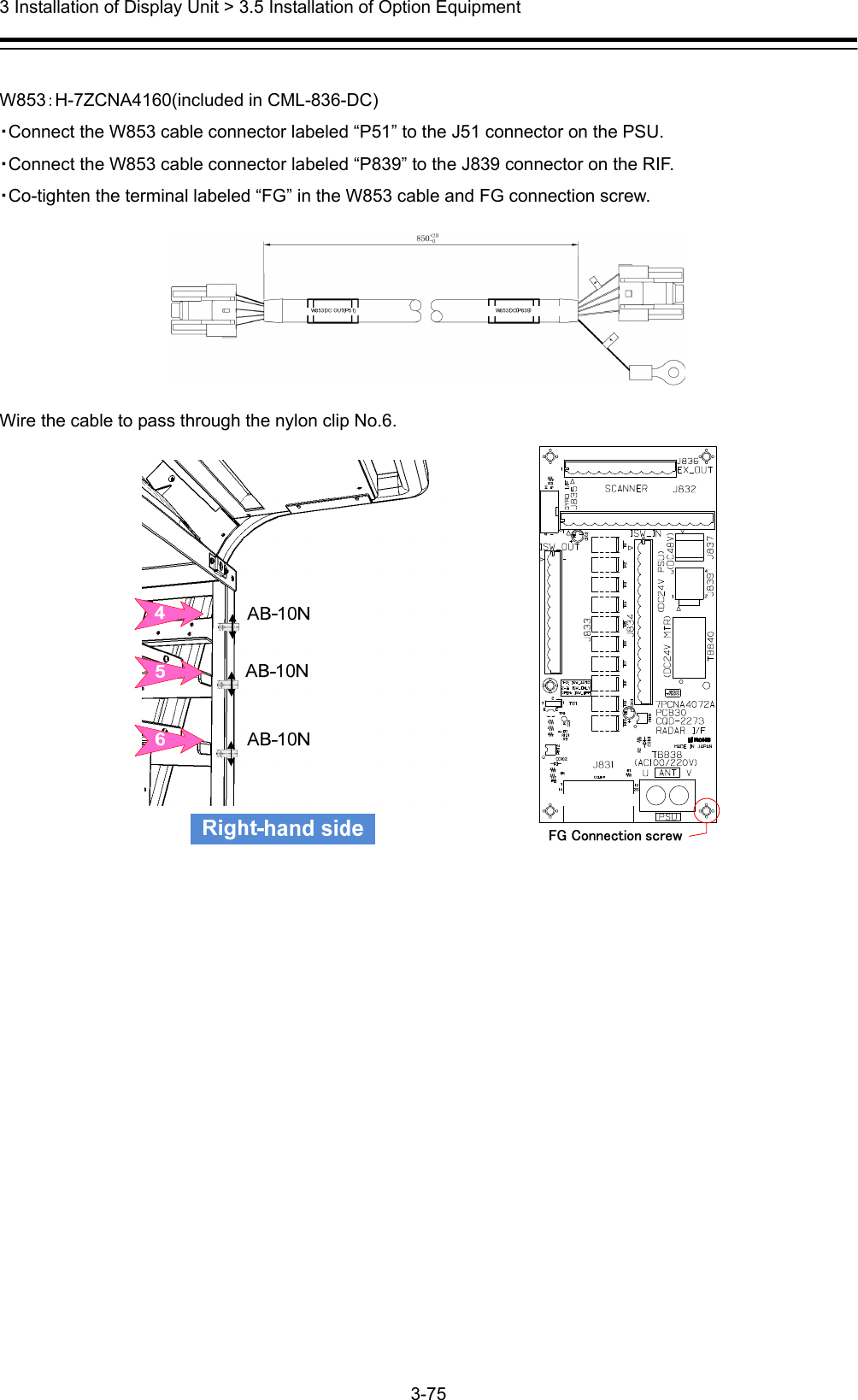
Installation Manual Part 4
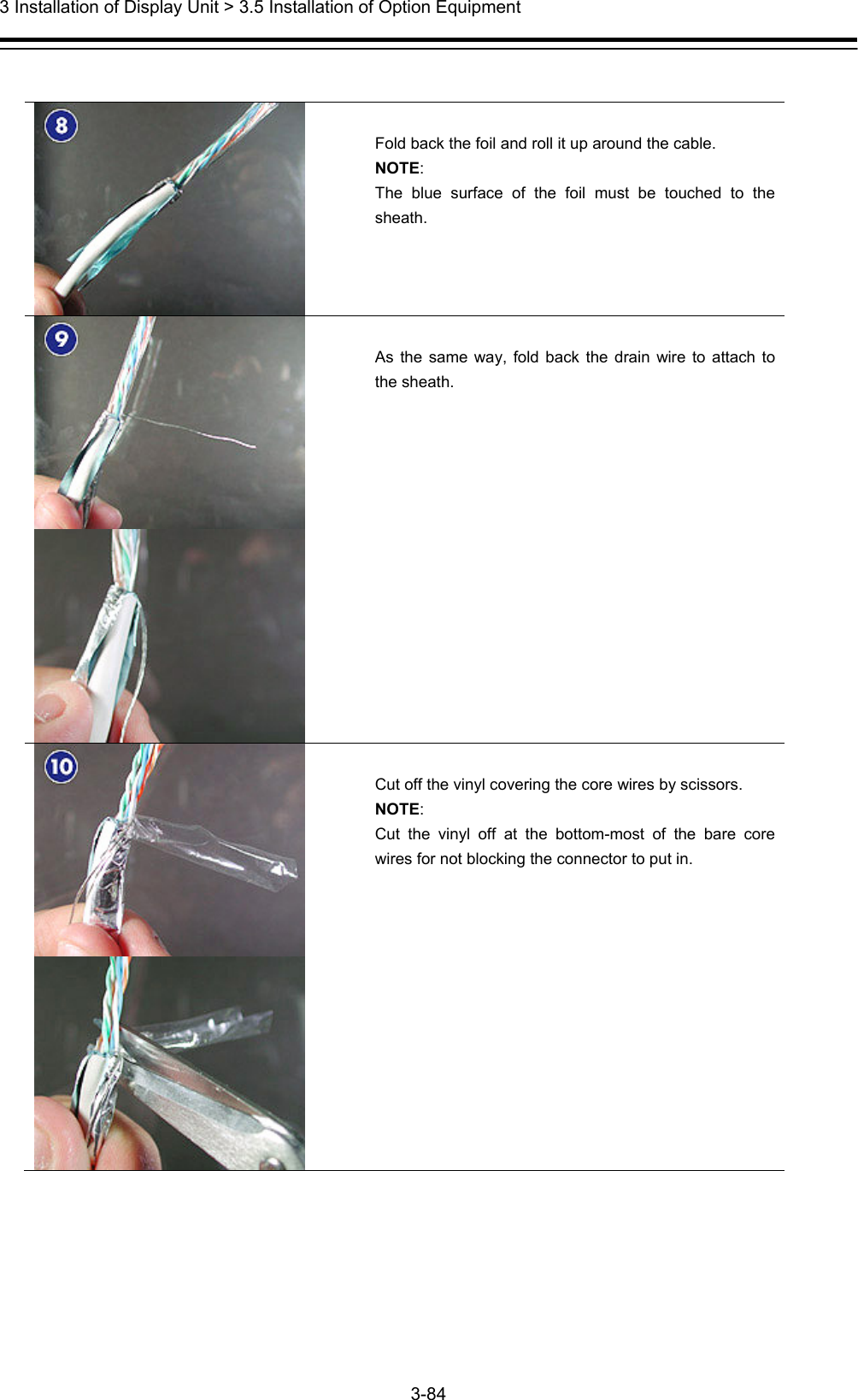
![3 Installation of Display Unit > 3.5 Installation of Option Equipment 3-83 Check by bending the cable that the foil inside is not damaged. If the foil inside is damaged, cut the cable there and go back to the procedure 2 again. [Failure example] The foil is torn and the core wires inside can be seen. Cut the sheath by a cutter vertically from the cut line made by the stripper in the procedure 3. NOTE: Do not damage the foil inside. Twist the cable to split off the sheath. Peel the sheath along the cut lines made by the stripper and the cutter. Check that the foil is not damaged after the sheath is peeled. The foil is OK if it is not torn by the pull of the arrow direction shown in the left figure. Failure example](https://usermanual.wiki/Japan-Radio-Co/NKE2632.Installation-Manual-Part-4/User-Guide-2791037-Page-9.png)