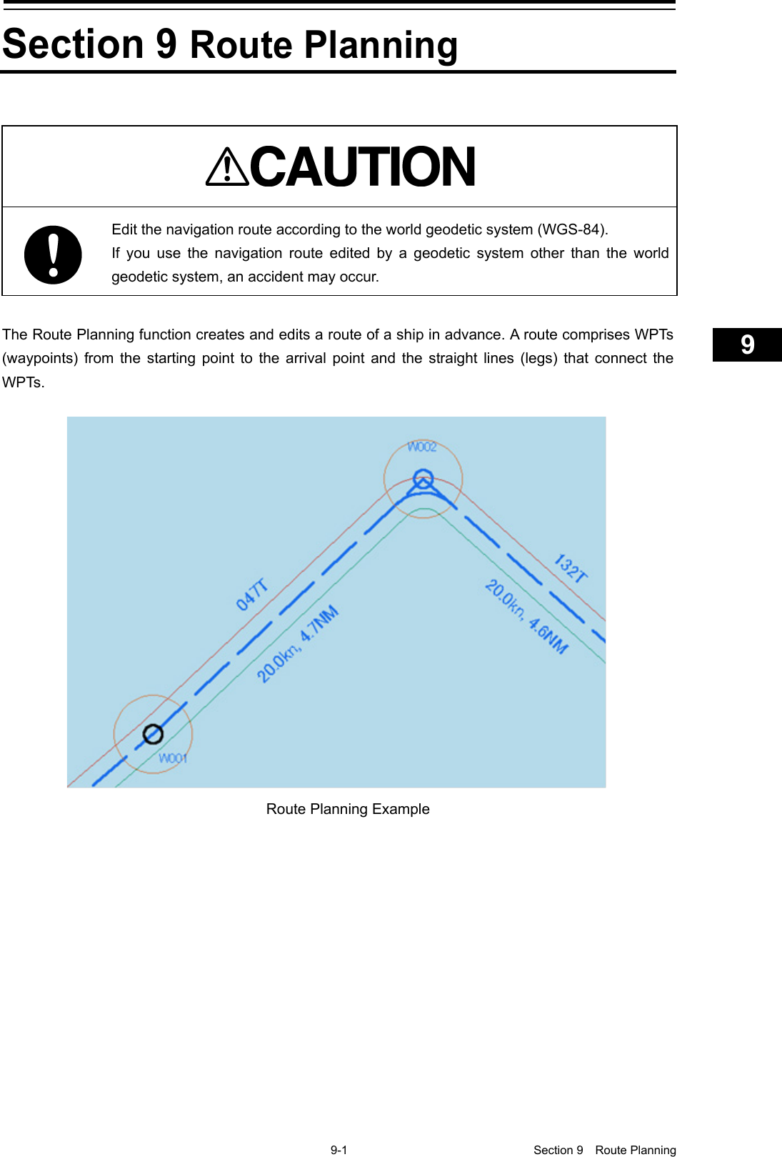
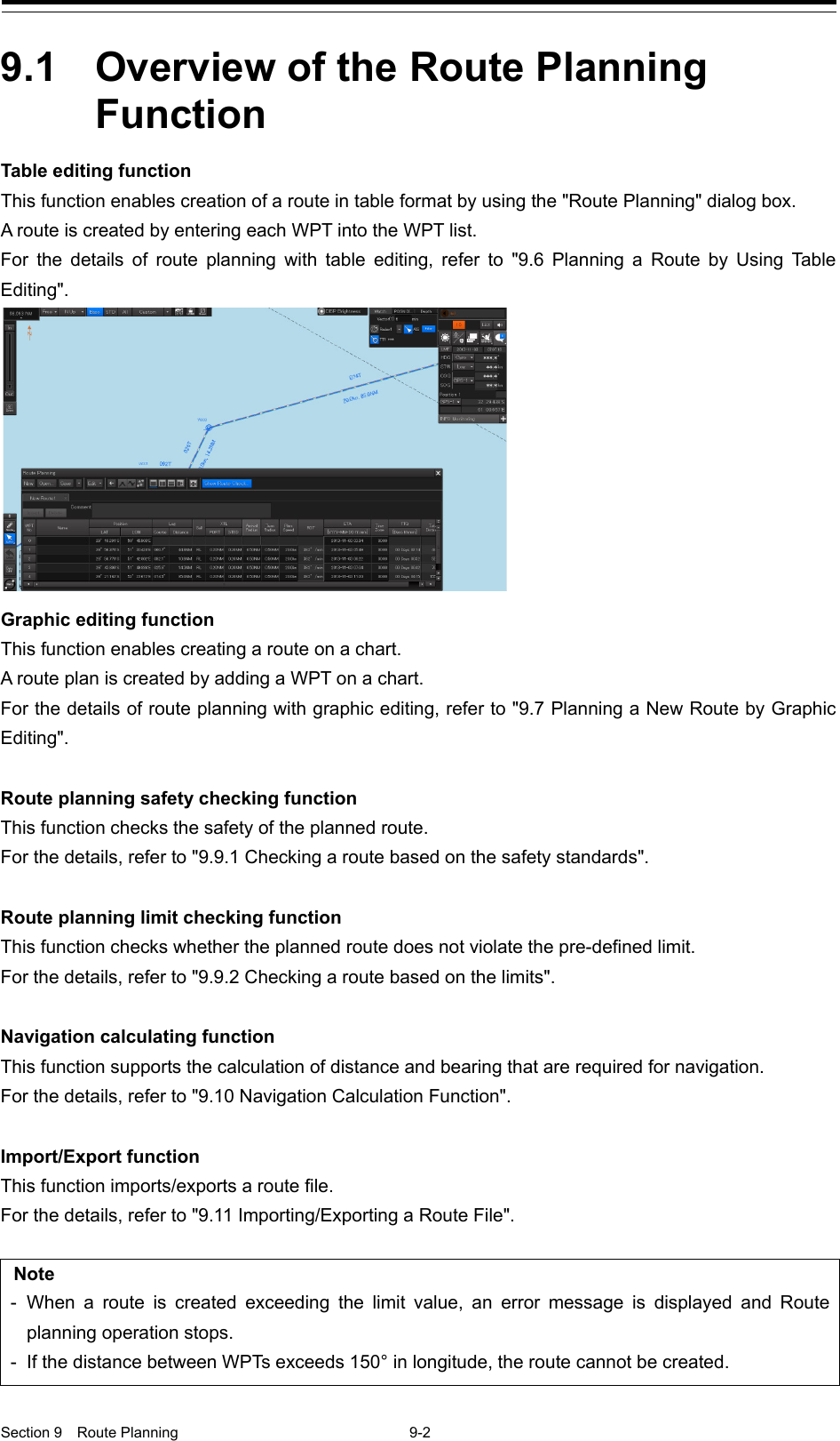
Japan Radio Co NKE2632 Solid State S-Band Marine Radar User Manual Instruction Manual Funtion Part 3
Japan Radio Co Ltd. Solid State S-Band Marine Radar Instruction Manual Funtion Part 3
Contents
- 1. Installation Manual Part 1
- 2. Installation Manual Part 2
- 3. Installation Manual Part 3
- 4. Installation Manual Part 4
- 5. Installation Manual Part 5
- 6. Installation Manual Part 6
- 7. Installation Manual Part 7
- 8. Installation Manual Part 8
- 9. Installation Manual Part 9
- 10. Installation Manual Part 10
- 11. Installation Manual Part 11
- 12. Instruction Manual Operation Part 1
- 13. Instruction Manual Operation Part 2
- 14. Instruction Manual Operation Part 3
- 15. Instruction Manual Operation Part 4
- 16. Instruction Manual Funtion Part 1
- 17. Instruction Manual Funtion Part 2
- 18. Instruction Manual Funtion Part 3
- 19. Instruction Manual Funtion Part 4
- 20. Instruction Manual Funtion Part 5
- 21. Instruction Manual Funtion Part 6
Instruction Manual Funtion Part 3
![8-47 Section 8 Functions of the ECDIS (Option) 1 2 3 4 5 6 7 8 9 10 11 12 13 14 15 16 17 18 19 20 21 22 23 24 25 26 27 8.11.1.4 Verifying Chart Update History When the [Update History] tab of the display switching tab is clicked on, chart update history is displayed. Memo This function is not available under C-M A P. If the chart update history consists of multiple pages and cannot be displayed on one page of the screen, drag the scroll bar to display the rest. Separator of chart update history Scroll bar](https://usermanual.wiki/Japan-Radio-Co/NKE2632.Instruction-Manual-Funtion-Part-3/User-Guide-2791062-Page-1.png)
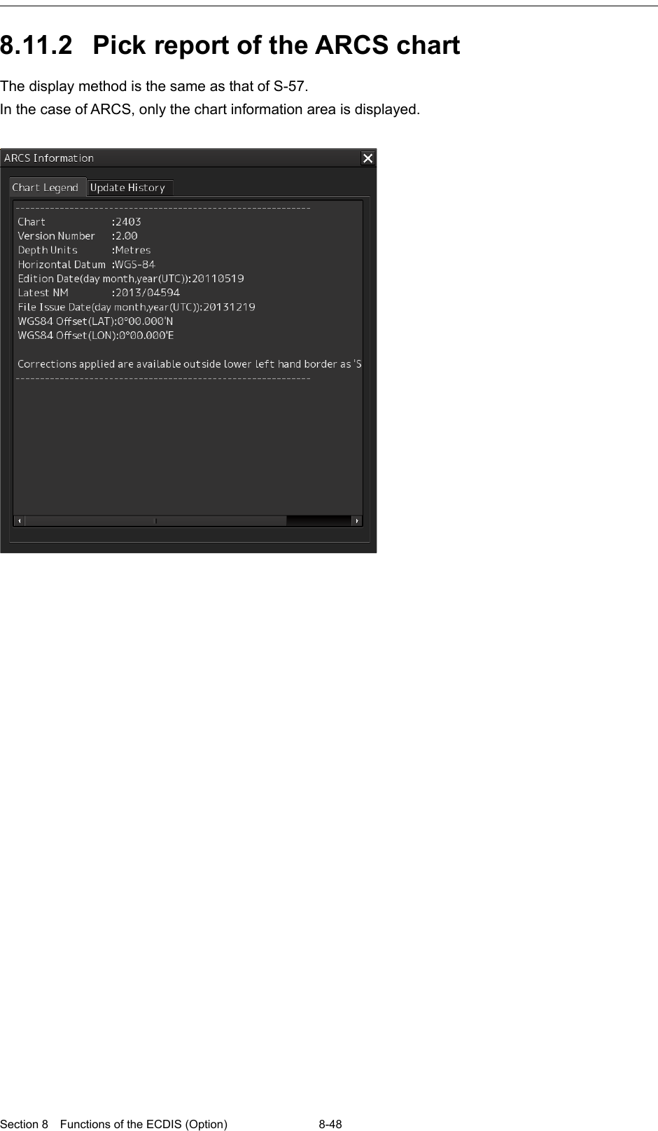
![8-49 Section 8 Functions of the ECDIS (Option) 1 2 3 4 5 6 7 8 9 10 11 12 13 14 15 16 17 18 19 20 21 22 23 24 25 26 27 8.11.3 Manual Update Pick Report 8.11.3.1 Displaying a Manual Update Pick Report 1 Click the right button on the object that was created by manual update. A pick mark and the context menu are displayed. 2 Click on [Readout Manual Update Information] on the context menu. The "Manual Update Information" dialog box appears.](https://usermanual.wiki/Japan-Radio-Co/NKE2632.Instruction-Manual-Funtion-Part-3/User-Guide-2791062-Page-3.png)
![Section 8 Functions of the ECDIS (Option) 8-50 8.12 Marking the Position of Own Ship with an Event Mark While sailing, you can mark the position of own ship on the chart with an event mark. 1 Click on the [Event] button in Chart Information Area. An event mark is marked to the position of own ship and the "Property" dialog box of event marks appears. The display position, ID, and date and time of creation of the event mark are displayed in the "Property" dialog box. Enter any desired comment in the [Comment] input box. [Deleting the Event Mark] The event mark can be deleted by either of the following methods. • Right-click on the event mark and click on [Delete this object] on the Context menu that appears. • Click on the event mark when in the Delete mode. Event mark](https://usermanual.wiki/Japan-Radio-Co/NKE2632.Instruction-Manual-Funtion-Part-3/User-Guide-2791062-Page-4.png)
![8-51 Section 8 Functions of the ECDIS (Option) 1 2 3 4 5 6 7 8 9 10 11 12 13 14 15 16 17 18 19 20 21 22 23 24 25 26 27 8.13 Displaying Radar Images on a Chart by Overlaying Radar images can be displayed by overlaying on the chart. Note • To perform overlay display of radar images, the radar function must be installed and radar images must be received from the radar system. • If the radar system displays a short-range image and a long-range image on the ECDIS at the same time, the radar image on the ECDIS may be distorted. • While the radar image is displayed, the display range can be changed in 11 steps (0.125/0.25/0.5/0.75/1.5/3/6/12/24/48/96 NM). • In the case of ARCS charts, the display range varies with the chart to be displayed. If a range over 120 NM is selected, radar image display automatically turns off. • The screen display color will automatically change to [Day3] when RADAR Overlay is turned on. (When the screen display color is Dusk/Night, automatic switching does not occur.) • When Multi View is used, radar images canot be displayed on View2.](https://usermanual.wiki/Japan-Radio-Co/NKE2632.Instruction-Manual-Funtion-Part-3/User-Guide-2791062-Page-5.png)
![Section 8 Functions of the ECDIS (Option) 8-52 8.13.1 Turning On/Off overlay display 1 Click on the [Menu] button on the left toolbar. The menu is displayed. 2 Select [View] - [Options] - [RADAR] on the menu. 3 Select the [RADAR Overlay] check box. Radar overlay display is set to On. 4 Select a radar system to be used from the pull-down menu. Memo When multiple radar systems are available, click the [RADAR Overlay] combo box and then select the radar image to be used from the pull-down menu that appears. (Radar images can be selected from the maximum of 8 systems, [RADAR1] to [RADAR8].)](https://usermanual.wiki/Japan-Radio-Co/NKE2632.Instruction-Manual-Funtion-Part-3/User-Guide-2791062-Page-6.png)
![8-53 Section 8 Functions of the ECDIS (Option) 1 2 3 4 5 6 7 8 9 10 11 12 13 14 15 16 17 18 19 20 21 22 23 24 25 26 27 [Transparency Setting of Echo/Trails] Transparency can be set up by clicking the [Transparency of Echo/Trails] slider handle to right and left. Opacity Transparency](https://usermanual.wiki/Japan-Radio-Co/NKE2632.Instruction-Manual-Funtion-Part-3/User-Guide-2791062-Page-7.png)
![Section 8 Functions of the ECDIS (Option) 8-54 8.13.2 Turning On/Off range ring display 1 Click on the [Menu] button on the left toolbar. The menu is displayed. 2 Select [View] - [Options] - [Tools] on the menu. 3 To show range rings, select [Range Rings]. To hide range rings, clear it.](https://usermanual.wiki/Japan-Radio-Co/NKE2632.Instruction-Manual-Funtion-Part-3/User-Guide-2791062-Page-8.png)
![8-55 Section 8 Functions of the ECDIS (Option) 1 2 3 4 5 6 7 8 9 10 11 12 13 14 15 16 17 18 19 20 21 22 23 24 25 26 27 8.13.3 Turning On/Off bearing scale 1 Click on the [Menu] button on the left toolbar. The menu is displayed. 2 Select [View] - [Options] - [Tools] on the menu. 3 To show a bearing scale, check [Bearing Scale]. To hide a bearing scale, clear it.](https://usermanual.wiki/Japan-Radio-Co/NKE2632.Instruction-Manual-Funtion-Part-3/User-Guide-2791062-Page-9.png)
![Section 8 Functions of the ECDIS (Option) 8-56 8.13.4 Radar image adjustment Radar images can be adjusted using the [RAIN], [SEA] and [GAIN] dials on the keyboard operation unit. [RAIN] dial: Suppressing rain and snow clutter The [RAIN] dial suppresses clutter caused by rain and snow. Turning the [RAIN] dial to the right enhances the contours of targets that are hidden in images of rain and snow. Take care not to over-adjust this dial. Otherwise, you may miss small targets. This dial also reduces sea clutter. So, using both the [RAIN] and [SEA] dials is more effective. Normally, keep this dial turned as far as possible to the left. [SEA] dial: Suppressing sea clutter The [SEA] dial lowers the gain at a short range to reduce sea clutter. Turning the [SEA] dial to the right increases the effect of suppressing sea clutter. Take care not to over-adjust this dial. Otherwise, you may miss small targets like buoys and small boats. [GAIN] dial: Adjusting sensitivity The [GAIN] dial adjusts the gain of RADAR echo. Turning the [GAIN] dial to the right increases the gain and widens the range in which RADAR echo can be observed. Take care not to over-adjust this dial, as reception noise on screen increases. This worsens the contrast and makes it more difficult to tell the difference between targets and RADAR echo. Alternatively, turning the [GAIN] dial to the left to view at a short range or screens containing closely packed targets, decreases the gain making targets easier to view. Take care not to over-adjust this dial. Otherwise, you may miss small targets. Memo If the keyboard operation unit is not available, the radar image can be adjusted using [Rain], [Sea] or [Gain] slider in the setting dialog of [Settings]- [Signal Process (Basic)] on the menu. The "Signal Process (Basic)" setting dialog can also be displayed by operating the [RAIN], [SEA], or [GAIN] dials on the keyboard operation unit. When one of the dials is held down (for 2 seconds or more) at operation termination, the setting dialog is closed. For the details of the "Signal Process(Basic)" setting dialog, refer to "18.2 Basic setting of radar signal processing".](https://usermanual.wiki/Japan-Radio-Co/NKE2632.Instruction-Manual-Funtion-Part-3/User-Guide-2791062-Page-10.png)
![8-57 Section 8 Functions of the ECDIS (Option) 1 2 3 4 5 6 7 8 9 10 11 12 13 14 15 16 17 18 19 20 21 22 23 24 25 26 27 8.14 Setting a true bearing When a gyro signal is input by using GYRO I/F, sometimes the true bearing value indicated by the master gyro and the true bearing value indicated by this equipment do not match. In this case, set the true bearing value of this equipment to the value of the master gyro by using the following procedure. 1 Click on the [Menu] button on the left toolbar. The menu is displayed. 2 Click on [Settings] - [General] on the menu. The "General" dialog is displayed. 3 Click on the [GYRO Setting] input box. 4 Enter the master gyro value through the software keyboard.](https://usermanual.wiki/Japan-Radio-Co/NKE2632.Instruction-Manual-Funtion-Part-3/User-Guide-2791062-Page-11.png)
![Section 8 Functions of the ECDIS (Option) 8-58 8.15 Setting an own ship’s speed 8.15.1 Switching an own ship’s speed sensor 1 Click on the STW Source combo box of the own ship’s information 2 Select a sensor source in the [STW] combo box. Any of the following sensor sources can be selected. MAN Logx ("x" indicates the equipment number) When [Menu] is selected, the "Sensor Selection/Status" dialog is displayed. When [MAN] (Manual) is selected, a speed through water can be input in the "Sensor Selection/Status" dialog. • When using 1-axis log, heading speed component can be detected, but transverse speed component cannot be detected. Then leeway effect (component drifted by wind) cannot be detected. • When using 2-axes log, its accuracy in shallow waters may be deteriorated, and its speed in deep sea areas may be unable to be detected. • When using a GPS, COG accuracy is less than ±3° at speed: from 1kn to 17kn, and is less than ±1° at speed: more than 17kn.](https://usermanual.wiki/Japan-Radio-Co/NKE2632.Instruction-Manual-Funtion-Part-3/User-Guide-2791062-Page-12.png)
![8-59 Section 8 Functions of the ECDIS (Option) 1 2 3 4 5 6 7 8 9 10 11 12 13 14 15 16 17 18 19 20 21 22 23 24 25 26 27 8.15.2 Entering the ship’s heading/own ship’s speed manually When the device (example: LOG) that is connected to this equipment fails to function, the target tracking device and true motion display can be used by entering the ship’s heading/own ship’s speed manually by using the following procedure. 1 Select [Menu] from the corresponding combo box. The "Sensor Selection/Status" dialog box appears. 2 To enter the ship’s heading manually, select [Manual] from the [Heading] combo box. To enter the ship’s own speed manually, select [Manual] from the [STW] combo box. 3 Click on the input combo box. 4 Enter numeric values through the software keyboard.](https://usermanual.wiki/Japan-Radio-Co/NKE2632.Instruction-Manual-Funtion-Part-3/User-Guide-2791062-Page-13.png)

![9-3 Section 9 Route Planning 1 2 3 4 5 6 7 8 9 10 11 12 13 14 15 16 17 18 19 20 21 22 23 24 25 26 27 9.2 Setting Route Display Before creating a route, set route display (display/hide of the route information to be displayed on the screen) at route setting. Use the following two dialogs for the setting. 9.2.1 Setting [Route] after selecting [View] - [Options] on the menu 1 Click on the [Menu] button on the left toolbar. The menu is displayed. 2 Click on the [View] - [Options] - [Route] on the menu. The "Route" setting screen is displayed. Ship's speed and distance Arrival radius Port side (red line) and width of port side Starboard side (green line) and width of starboard side WPT: Waypoint Leg Arrival circle](https://usermanual.wiki/Japan-Radio-Co/NKE2632.Instruction-Manual-Funtion-Part-3/User-Guide-2791062-Page-17.png)
![Section 9 Route Planning 9-4 [1] [Show ETA] By selecting the [ETA] check box, the display of the ETA (estimated time of arrival to WPT) becomes effective at route monitoring. When [UTC] from [Format] is clicked, UTC is displayed and when [LMT] is clicked, LMT is displayed. [1] [2] [3] Not selecting the [ETA] check box Selecting the [Show ETA] check box, and clicking [UTC] as the arrival time display format Selecting the [Show ETA] check box, and clicking [LMT] as the arrival time display format](https://usermanual.wiki/Japan-Radio-Co/NKE2632.Instruction-Manual-Funtion-Part-3/User-Guide-2791062-Page-18.png)
![9-5 Section 9 Route Planning 1 2 3 4 5 6 7 8 9 10 11 12 13 14 15 16 17 18 19 20 21 22 23 24 25 26 27 [2] [Cross Track Limit Line] When this item is selected, a cross track limit line is displayed. When this item is selected, the line color can be set. When [IALA-A] is clicked on, the starboard side is displayed in green and the port side is displayed in red. When [IALA-B] is clicked on, the starboard side is displayed in red and the port side is displayed in green. [3] [Show WPT Name](Show comment) When this item is selected, a comment is displayed near the WPT. When this item is selected, the character size of the comment can be set. When [Standard] is clicked on, the comment is displayed in the standard character size. When [Small] is clicked on, the comment is displayed in the character size smaller than the standard size. 9.2.2 Setting [Settings] - [Route] on the menu 1 Click on the [Menu] button on the left toolbar. The menu is displayed. 2 Click on the [Settings] - [Route] on the menu. The "Route" dialog is displayed. [1] [Default] (Factory settings) Set factory settings of the route display that is created at route planning. [XTL(PORT)]: Set a port side cross track limit. [XTL(STBD)]: Set a starboard side cross track limit. [1] [2] [3] [4] [5]](https://usermanual.wiki/Japan-Radio-Co/NKE2632.Instruction-Manual-Funtion-Part-3/User-Guide-2791062-Page-19.png)
![Section 9 Route Planning 9-6 [Arrival radius]: Set an arrival radius of WPT. [Speed]: Set a planned ship’s speed. [Sail]: Select sailing mode. - When [RL] is selected, the mode is set to Rhumb Line. - When [GC] is selected, the mode is set to Great Circle. [Turn radius]: Set a turning radius. [Time zone] combo box: Set a time zone. Display Example Display Example](https://usermanual.wiki/Japan-Radio-Co/NKE2632.Instruction-Manual-Funtion-Part-3/User-Guide-2791062-Page-20.png)
![9-7 Section 9 Route Planning 1 2 3 4 5 6 7 8 9 10 11 12 13 14 15 16 17 18 19 20 21 22 23 24 25 26 27 [2] [Distance calculation mode] Set a method for calculating a distance between WPTs. When [Straight] is selected, a distance between WPTs is calculated with a straight line When [with Turn] is selected, a distance between WPTs is calculated based on the expected route. [3] [Monitoring] Set a route monitoring method. When [Wheel-over line] (steering line) is selected, monitoring is performed by using Wheel-over line (WOL) along each WPT. When [Arrival circle] is selected, monitoring is performed by using the arrival circle along each WPT. WPT 1 WPT 2 WPT 3 WPT 1 WPT 2 WPT 3 Wheel over line Arrival circle](https://usermanual.wiki/Japan-Radio-Co/NKE2632.Instruction-Manual-Funtion-Part-3/User-Guide-2791062-Page-21.png)
![Section 9 Route Planning 9-8 [4] [MAX Latitude] Set maximum latitude. A WPT can no longer be entered in a latitude higher than the latitude that has been set up. If sailing is [GC], it is possible to create a route by automatically adding WPTs so as not to exceed the maximum latitude in the case of a route in which part of the leg passes a latitude higher than the maximum latitude. If the maximum latitude is 60° or higher, a route can be created even if the GC leg exceeds 60°. If the GC leg exceeds 60° when the maximum latitude is 60°, WPTs are automatically added and the route is adjusted so as not to exceed 60°. Note: A route cannot be created with a leg of 150° or higher in the longitudinal direction. [5] [Minimum Leg Length for Limit Check] combo box Select a multiplier for determining the "minimum leg length" that is used for limit check from 1, 2, 4, 6, or 8. Calculation expression: Minimum leg length = (Hull length) x multiplier 60°N 60°N WPTs (W001 and W002) in this example are added so as not to exceed the maximum latitude (60°). The segment between W001 and W002 becomes an RL leg.](https://usermanual.wiki/Japan-Radio-Co/NKE2632.Instruction-Manual-Funtion-Part-3/User-Guide-2791062-Page-22.png)
![9-9 Section 9 Route Planning 1 2 3 4 5 6 7 8 9 10 11 12 13 14 15 16 17 18 19 20 21 22 23 24 25 26 27 9.3 Starting and Ending the Route Planning Dialog Box Plan a route on the "Route Planning" dialog box. The procedures for starting and ending the "Route Planning" dialog box are as follows. 9.3.1 Starting the "Route Planning" dialog box 1 Click on the [Menu] button on the left toolbar. The top menu is displayed. 2 Click on the [Route Planning] button on the top menu. The "Route Planning" dialog box appears on the screen. The width of the dialog box varies according to the screen size. 9.3.2 Ending the "Route Planning" dialog box 1 Click on the [X] button on the dialog box. Display Example](https://usermanual.wiki/Japan-Radio-Co/NKE2632.Instruction-Manual-Funtion-Part-3/User-Guide-2791062-Page-23.png)
![Section 9 Route Planning 9-10 9.4 Name and Function of Each Section of the "Route Planning" Dialog Box The "Route Planning" dialog box comprises as below. Name Function Title bar Displays the menu title, "Route Planning". Route Planning bar Route planning tools are assigned (Refer to "9.4.1 Route Planning bar".). Route planning tab Displays the file name and route data of the route file that is being created (Refer to "9.4.2 Route planning tab".). 9.4.1 Route Planning bar The Route Planning bar comprises the following tools. [1] [New] button When this button is clicked on, a new route planning tab is added to the dialog box, enabling creation of a new route file. Note Up to four route files can be opened concurrently. If four files have already been opened, the [New] button is disabled. To create a new route file, close one or more of the files that are opened and click on the [New] button. Title bar Route planning bar Route planning tab [6] [7] [1] [2] [3] [4] [5] [8] [9]](https://usermanual.wiki/Japan-Radio-Co/NKE2632.Instruction-Manual-Funtion-Part-3/User-Guide-2791062-Page-24.png)
![9-11 Section 9 Route Planning 1 2 3 4 5 6 7 8 9 10 11 12 13 14 15 16 17 18 19 20 21 22 23 24 25 26 27 [2] [Open…] button When this button is clicked on, the "File Operations" (Open a file) dialog box appears and a required file can be selected and opened from the route list of the files that have been saved. Note Up to four route files can be opened concurrently. If four files have already been opened, the [Open] button is disabled. To open from the saving list, close one or more of the files that are opened and click on the [Open] button. [3] [Save] button When the [Save] button is clicked on, the route file is saved. For the details, refer to "9.5 Saving a Route". [4] Route planning menu button When this button is clicked on, the route planning menu is displayed. The following operations can be performed by using the route planning menu. Menu button name Function Related section [New] Creates a new route file. 9.6.2 Creating a new route file by table editing 9.7.2 Creating a new route file by graphic editing [File operation…] Displays the "File operation" dialog box. 9.6.4 Editing a route by table editing [Save] (overwrite save) Saves a route file by overwriting. 9.5 Saving a Route [Save as…] Saves a route file by naming the file. 9.5 Saving a Route [Import] Displays the "Import" dialog box. 9.11.1 Importing a route file [Export] Displays the "Export" dialog box. 9.11.2 Exporting a route file [Setting…] Displays the "Route" dialog box for setting initial values of the route at route planning. 9.2.2 Setting [Settings] - [Route] on the menu](https://usermanual.wiki/Japan-Radio-Co/NKE2632.Instruction-Manual-Funtion-Part-3/User-Guide-2791062-Page-25.png)
![Section 9 Route Planning 9-12 [5] [Edit] button When this button is clicked on, the Edit menu is displayed. The following operations can be performed by using the Edit menu. Menu button name Function Related section [Use EBL/VRM] When this item is selected by clicking on the item, the EBL/VRM mode that enables creation of a route by using EBL and VRM becomes available. When the item is clicked on again, the check mark is cleared and EBL/VRM mode is cancelled. 9.7.2.1 Creating a route by using EBL/VRM [Use Assistant circle] When this item is selected by clicking on the item, the Use Assistant circle mode that enables creation of a route by using an assistant circle (supplementary line) becomes available. When the item is clicked on again, the check mark is cleared and the Use Assistance circle mode is cancelled. 9.7.2.2 Creating a route by using the assistant circle function [WPT Reverse Order] When this item is selected by clicking on the item, the order of the WPT that is currently selected can be reversed. -](https://usermanual.wiki/Japan-Radio-Co/NKE2632.Instruction-Manual-Funtion-Part-3/User-Guide-2791062-Page-26.png)
![9-13 Section 9 Route Planning 1 2 3 4 5 6 7 8 9 10 11 12 13 14 15 16 17 18 19 20 21 22 23 24 25 26 27 [6] Display area switching button Chart display can be changed to the display area/scale suitable for the editing. Button name Function [Previous] Switches the chart display to the display area/scale before the chart display was switched. [Display centered WPT] Displays the WPT that is currently being edited at the center of the chart. [Display WPT-WPT] Displays on the chart the WPT that is currently being edited and the previous WPT. [Display entire route] Displays the entire route that is being edited on the chart. Center of WPT Between WPTs Previous Display WPT-WPT Display centered WPT Display entire route](https://usermanual.wiki/Japan-Radio-Co/NKE2632.Instruction-Manual-Funtion-Part-3/User-Guide-2791062-Page-27.png)
![Section 9 Route Planning 9-14 [7] Multi view switching button A method of splitting a chart can be selected. Button name Function Display image [Single View] Displays a chart on a single screen. [Right Left View] Displays a chart by splitting it into 2 screens of left and right. [Top Bottom View] Displays a chart by splitting it into top and bottom. [Picture in Picture] (Dialog view) Displays a dialog box of another chart inside of the chart screen. Single View Top Bottom View Right Left View Floating View](https://usermanual.wiki/Japan-Radio-Co/NKE2632.Instruction-Manual-Funtion-Part-3/User-Guide-2791062-Page-28.png)
![9-15 Section 9 Route Planning 1 2 3 4 5 6 7 8 9 10 11 12 13 14 15 16 17 18 19 20 21 22 23 24 25 26 27 [8] [Display full] (Full screen display) button A chart can be displayed in full screen mode by clicking on this button that clears the operation section and display section other than the "Route Planning" dialog box. When this button is clicked on again, the operation section and the display section are re-displayed. [9] [Show Route Check…] (Route check screen display) button When this button is clicked on, the "Check Route" dialog appears. When an error is detected, the error count is displayed with a badge. For the details of the "Check Route" dialog, refer to "9.9 Checking Route Data". 9.4.2 Route planning tab When a route file is opened, a route plan tab comprising a file name display section and route data is displayed. Up to four route planning tabs can be displayed concurrently. File name display section The file names that are currently opened are displayed in the tabs. When the display of the file name is clicked on, the route file can be switched. "*" is attached to the top of the name of the file you are editing. A badge is displayed on the name of the file that is being monitored or under automatic sailing. When the [X] button on the file name display section is clicked on, the tab is closed. If an attempt is made to close the tab that has not been saved, a save confirmation message dialog box appears. Usual display Full screen display Error count Monitoring badge Automatic sailing badge](https://usermanual.wiki/Japan-Radio-Co/NKE2632.Instruction-Manual-Funtion-Part-3/User-Guide-2791062-Page-29.png)
![Section 9 Route Planning 9-16 To close the tab by saving the route file by overwriting, click on the [Yes] button. When not saving the route file by overwriting, click on the [No] button. When the [X] button is clicked on, the file returns to the state prior to the clicking on the [X] button on the file name display section. Route data WPTs that form the route and the WPT data are displayed in a list. [1] [Insert] button A new WPT is inserted in the selected WPT. [2] [Delete] button The selected WPT is deleted. [3] [Comment] field The comment of the route file is displayed. [4] WPT list Data of each WPT is displayed. Route Data [1] [2] [3] [4]](https://usermanual.wiki/Japan-Radio-Co/NKE2632.Instruction-Manual-Funtion-Part-3/User-Guide-2791062-Page-30.png)
![9-17 Section 9 Route Planning 1 2 3 4 5 6 7 8 9 10 11 12 13 14 15 16 17 18 19 20 21 22 23 24 25 26 27 9.5 Saving a Route 1 Click on the [Save] button on the Route Planning bar. Or select the [Save] button that is displayed by clicking on the Route Planning menu button At creation of a new route, a "Save as Route File" dialog box appears. Perform Steps 2 to 4 in the "Save as Route File" dialog. When the existing route file is saved, the "Save as Route File" dialog box does not appear since the file is overwritten. 2 Enter [Name] and a comment in [Comment] as required. Memo When all the files that have been saved are opened, all the file names may not necessarily be displayed. Files can be distinguished easily by entering comments. 3 Click on the [Save] button. The file is saved.](https://usermanual.wiki/Japan-Radio-Co/NKE2632.Instruction-Manual-Funtion-Part-3/User-Guide-2791062-Page-31.png)
![Section 9 Route Planning 9-18 4 The file name that is displayed on the Route Planning tab changes to the name that is specified in the [Name] box. For the details of the Route Planning tab, refer to "9.4.2 Route planning tab". When a route of the same file name already exists 1 When file saving operation is performed, a dialog box message appears confirming whether the file is to be overwritten. 2 When overwriting the file, save the file by clicking on the [Yes] button. When not overwriting the file, close the dialog box by clicking on the [No] button and change the file name on the "Save as Route File" dialog box.](https://usermanual.wiki/Japan-Radio-Co/NKE2632.Instruction-Manual-Funtion-Part-3/User-Guide-2791062-Page-32.png)
![9-19 Section 9 Route Planning 1 2 3 4 5 6 7 8 9 10 11 12 13 14 15 16 17 18 19 20 21 22 23 24 25 26 27 Memo - The following message is displayed when an attempt is made to overwrite a protected file. To cancel the save operation, close the dialog box by clicking on the [OK] button or the [X] button. When saving the file by changing the file name, click on the [Save as...] button. The dialog box is closed and the "Save as Route File" dialog box appears. - The following message is displayed when an attempt is made to overwrite the route file that is currently being monitored. To cancel the save operation, click on the [No] button or [X] button. To continue the monitoring of the updated route by saving the route file by overwriting, click on the [Yes] button. When saving the file by changing the file name, click on the [Save as...] button. The dialog box is closed and the "Save as Route File" dialog box appears. - The following message is displayed when an attempt is made to overwrite the file of the route under automatic sailing. To cancel the save operation, close the dialog box by clicking on the [OK] button or the [X] button. When saving the file by changing the file name, click on the [Save as…] button. The dialog box is closed and the "Save as Route File" dialog box appears. The monitored route does not change by the save operation. Automatic sailing continues based on the pre-saved route. Saving a route file by naming the file Click on [Save as...] of the route planning menu button on the Route Planning bar. When the "Save as Route File" dialog box appears, save the file by entering a new file name.](https://usermanual.wiki/Japan-Radio-Co/NKE2632.Instruction-Manual-Funtion-Part-3/User-Guide-2791062-Page-33.png)
![9-21 Section 9 Route Planning 1 2 3 4 5 6 7 8 9 10 11 12 13 14 15 16 17 18 19 20 21 22 23 24 25 26 27 9.6 Planning a Route by Using Table Editing Edit the navigation route according to the world geodetic system (WGS-84). If you use the navigation route edited by a geodetic system other than the world geodetic system, an accident may occur. 9.6.1 Table editing operation flow 9.6.1.1 Creating a new route file 1 Start [Route Planning]. Reference: "9.3.1 Starting the "Route Planning" dialog box" 2 Create a new route file. Reference: "9.6.2 Creating a new route file by table editing" 3 Set WPTs from WPT0 to WPT of the final destination. Reference: "9.6.2 Creating a new route file by table editing" 4 Save the route. Reference: "9.5 Saving a Route" 5 End [Route Planning]. Reference: "9.3.2 Ending the "Route Planning" dialog box"](https://usermanual.wiki/Japan-Radio-Co/NKE2632.Instruction-Manual-Funtion-Part-3/User-Guide-2791062-Page-35.png)
![Section 9 Route Planning 9-22 9.6.1.2 Editing a route Steps 1 and 2 are not required when editing the route that is currently displayed. 1 Start [Route Planning]. Reference: "9.3.1 Starting the "Route Planning" dialog box" 2 Open the route file to be edited. Reference: "9.6.4 Editing a route by table editing" 3 Edit the route file. Reference: "9.6.4 Editing a route by table editing" 4 Save the route. Reference: "9.5 Saving a Route" 5 End [Route Planning]. Reference: "9.3.2 Ending the "Route Planning" dialog box"](https://usermanual.wiki/Japan-Radio-Co/NKE2632.Instruction-Manual-Funtion-Part-3/User-Guide-2791062-Page-36.png)
![9-23 Section 9 Route Planning 1 2 3 4 5 6 7 8 9 10 11 12 13 14 15 16 17 18 19 20 21 22 23 24 25 26 27 9.6.2 Creating a new route file by table editing 1 Click on the [New] button on the Route Planning bar Or select the [New] button that is displayed by clicking on the Route Planning menu button. A new tab is added. 2 Enter the latitude and the longitude of WPT0 (waypoint 0) Enter the latitude by clicking on [LAT] of [Position]. Enter the longitude by clicking on [LON] of [Position]. Use the software keyboard for entering the latitude and longitude. Latitude software keyboard Longitude software keyboard Range of the values that can be entered](https://usermanual.wiki/Japan-Radio-Co/NKE2632.Instruction-Manual-Funtion-Part-3/User-Guide-2791062-Page-37.png)
![Section 9 Route Planning 9-24 3 Set the following items as required. *Some items are for display only and cannot be set. Item Description [Name] Set a name of WPT. [Leg Course] This is the bearing from the previous WPT and is not set in WPT0. The specifiable range is from 0.0° to 359.9°. [Leg Distance] This is the distance from the previous WPT and is not set in WPT0. The specifiable range is from 0.0 to 9999.9 NM. [Sail] [RL] or [GC] can be selected from the list. [XTL PORT] (Port side cross track limit) Set a port side cross track limit. The specifiable range is from 0.01 to 9.99 NM. [XTL STBD] (Starboard side cross track limit) Set a starboard side cross track limit. The specifiable range is from 0.01 to 9.99 NM. [Arrival Radius] Sets the arrival radius. (0.01 to 9.99 NM) [Turn Radius] (Turning radius) Sets the turning radius. (0.00 to 9.99 NM) [Plan Speed] (Planned speed) Sets the planned ship’s speed. (1.0 to 99.9kn) [ROT] ROT is automatically calculated from the planned speed and turning radius. [ETA] ETA is automatically calculated from the position of WPT, planned speed, and time zone. [Time Zone] The time difference of the time of arrival can be input within the range from -13.30 to +13.30. [TTG] TTG can be automatically calculated from the position of WPT and planned speed. [Total Distance] This is the total distance between WPT0 and the final WPT. Memo The values that are set by selecting [Settings] – [Route] on the menu is reflected in [Sail], [XTL PORT], [XTL STBD], [Arrival radius], [Turn Radius], [Plan Speed], and [Time Zone]. For the details, refer to "18.12 Setting parameter values for automatic sailing ". 4 Add the next WPT by clicking on the next WPT No. or the [Insert] button after entering the latitude and longitude. WPT1 is added.](https://usermanual.wiki/Japan-Radio-Co/NKE2632.Instruction-Manual-Funtion-Part-3/User-Guide-2791062-Page-38.png)
![9-25 Section 9 Route Planning 1 2 3 4 5 6 7 8 9 10 11 12 13 14 15 16 17 18 19 20 21 22 23 24 25 26 27 5 Set the item as indicated in Step 3. 6 Enter data up to the last WPT with the same procedure. The route based on the input data is displayed each time. 7 After completing the creation, save the route file. For the saving procedure, refer to "9.5 Saving a Route". 9.6.3 Deleting WPT data 1 Select WPT data to be deleted and click on the [Delete] button. 9.6.4 Editing a route by table editing Memo Steps 1 and 2 are not required when editing the route that is currently displayed. 1 Click on the [Open] button on the Route Planning bar](https://usermanual.wiki/Japan-Radio-Co/NKE2632.Instruction-Manual-Funtion-Part-3/User-Guide-2791062-Page-39.png)
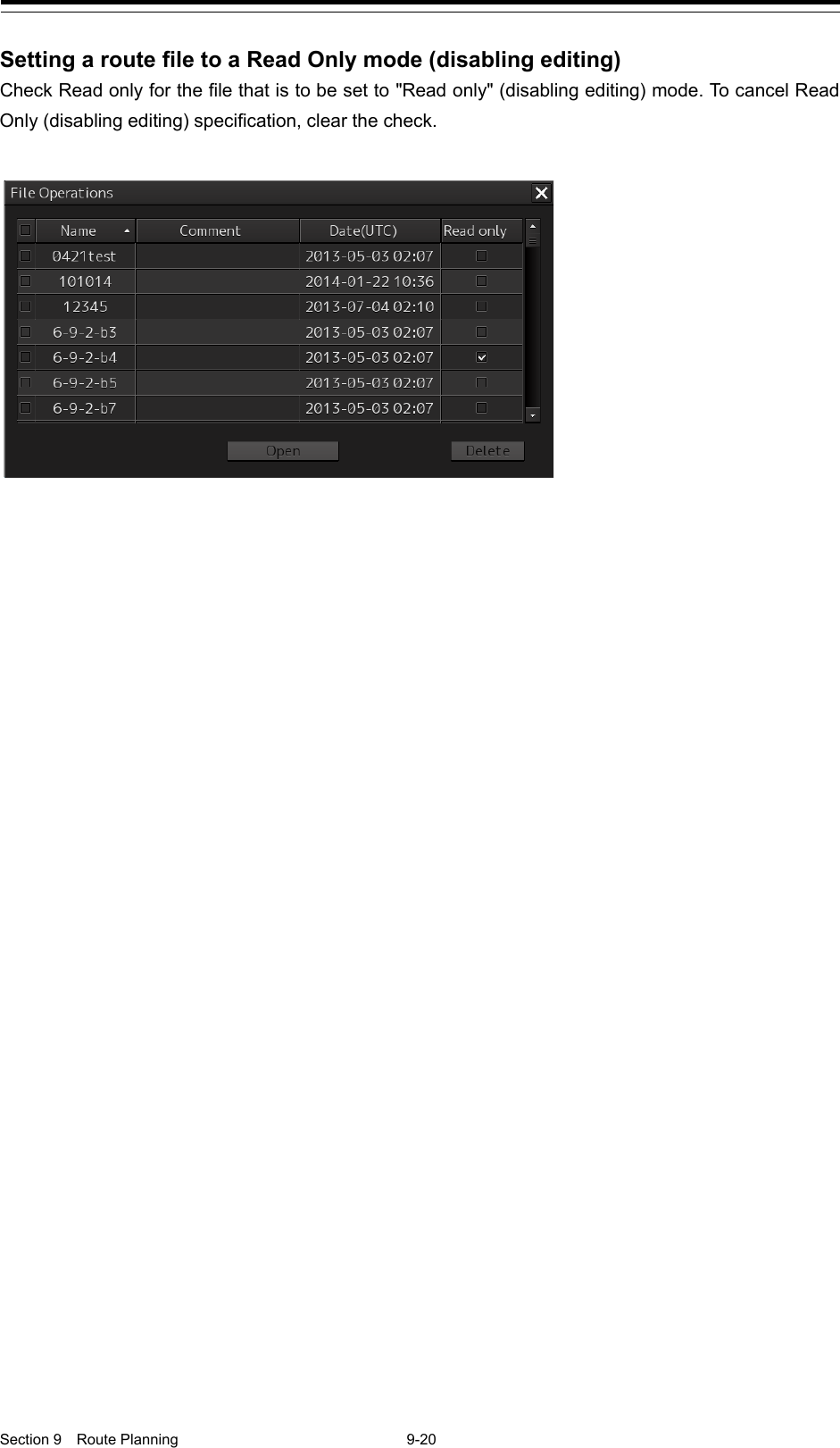
![Section 9 Route Planning 9-26 Or select the [File operation…] button that is displayed by clicking on the Route Planning menu button. The "File operation…" dialog box appears. 2 Select the route file to be edited and click on the [Open] button. Memo If [Read only] is selected, the file overwrite function is disabled. To overwrite the existing file, clear the item before opening the file. The route file is displayed on the "Route Planning" dialog box. For the details of the Route Planning tab, refer to "9.4.2 Route planning tab".](https://usermanual.wiki/Japan-Radio-Co/NKE2632.Instruction-Manual-Funtion-Part-3/User-Guide-2791062-Page-40.png)
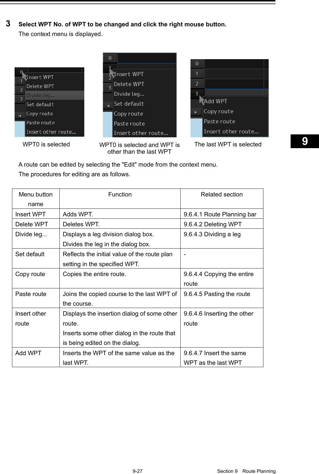
![Section 9 Route Planning 9-28 4 After completing the editing, click on the [Save] button on the Route Planning bar. Or select the [Save] button that is displayed by clicking on the Route Planning menu button For the details of save operation, refer to "9.5 Saving a Route ". 9.6.4.1 Inserting WPT Insert the WPT of the same value as the selected WPT. 1 Click the right mouse button on the WPT No. of the WPT to be inserted. The context menu is displayed. 2 Click on [Insert WPT] of the context menu. WPT is inserted following the selected WPT. 9.6.4.2 Deleting WPT Delete the selected WPT. 1 Click the right mouse button on the WPT No. of the WPT to be deleted. The context menu is displayed. 2 Click on [Delete WPT] on the context menu. The selected WPT is deleted.](https://usermanual.wiki/Japan-Radio-Co/NKE2632.Instruction-Manual-Funtion-Part-3/User-Guide-2791062-Page-42.png)
![9-29 Section 9 Route Planning 1 2 3 4 5 6 7 8 9 10 11 12 13 14 15 16 17 18 19 20 21 22 23 24 25 26 27 9.6.4.3 Dividing a leg A leg can be divided by setting a longitude or a nautical mile. 1 Click the right button on the WPT No. to be divided. The context menu is displayed. 2 Click on [Divide leg...] of the context menu. The "Divide Route" dialog box appears. 3 Enter a division interval. [Every (LON)] (Longitude division) 1) Click on "Every(LON)". 2) Enter a longitude interval for division. [Every(NM)] (Nautical mile division) 1) Click on "Every(NM)". 2) Enter a nautical mile interval for division. 4 Click on the [OK] button. The leg that is selected in Step 1 is divided in the unit that is specified in Step 3. Note When the total number of WPTs exceeds the maximum value of 511 as a result of leg division, leg division is executed within the range of 511 in the entire route. 9.6.4.4 Copying the entire route Copy the entire route that is selected. 1 Click the right mouse button on the WPT No. other than the last WPT. The context menu is displayed. 2 Click on [Copy route] on the context menu. The entire route is copied.](https://usermanual.wiki/Japan-Radio-Co/NKE2632.Instruction-Manual-Funtion-Part-3/User-Guide-2791062-Page-43.png)
![Section 9 Route Planning 9-30 9.6.4.5 Pasting the route The route that was copied to the last WEP of the route is merged. 1 Click the right mouse button on the WPT No. of the WPT on which the route is to be pasted. The context menu is displayed. 2 Click on [Paste route] in the context menu. The routes are pasted (inserted) Note After merging the copied route, when a route planning error occurs as a result of recalculation of the Course, Distance, Total Distance, ROT, TTG, and ETA, an error message is displayed and the route will not be merged Memo The same operation is performed also when the next No. button of the last WPT is clicked. 9.6.4.6 Inserting the other route Insert the route of some other file in the route that is being edited. 1 Click the right mouse button on WPT No. A context menu is displayed. 2 Click on [Insert other route] in the context menu. The "Insert other route" dialog box appears. 3 Select a route file to be inserted from the [Select Route] combo box. 4 Click on the [OK] button. The route file is inserted. Note If the range can be inserted is exceeded, an error message is displayed and the route will not be inserted.](https://usermanual.wiki/Japan-Radio-Co/NKE2632.Instruction-Manual-Funtion-Part-3/User-Guide-2791062-Page-44.png)
![9-31 Section 9 Route Planning 1 2 3 4 5 6 7 8 9 10 11 12 13 14 15 16 17 18 19 20 21 22 23 24 25 26 27 9.6.4.7 Insert the same WPT as the last WPT Insert the same WPT as the last WPT following the last WPT. 1 Click the right mouse button on the WPT No. of the last WPT. The context menu is displayed. 2 Click on [Add WPT] on the context menu. WPT is added following the last WPT.](https://usermanual.wiki/Japan-Radio-Co/NKE2632.Instruction-Manual-Funtion-Part-3/User-Guide-2791062-Page-45.png)
![Section 9 Route Planning 9-32 9.7 Planning a New Route by Graphic Editing Edit the navigation route according to the world geodetic system (WGS-84). If you use the navigation route edited by a geodetic system other than the world geodetic system, an accident may occur. 9.7.1 Graphic editing operation flow 9.7.1.1 Creating a new route file 1 Start [Route Planning]. Reference: "9.3.1 Starting the "Route Planning" dialog box" 2 Create a new route file. Reference: "9.7.1.1 Creating a new route file". 3 Set WPTs from WPT0 to the WPT of the final destination on the chart For the details, refer to the flowchart provided in "9.7.1.2 Editing a route file". 4 Save a route. Reference: "9.5 Saving a Route" 5 End [Route Planning]. Reference: "9.3.2 Ending the "Route Planning" dialog box"](https://usermanual.wiki/Japan-Radio-Co/NKE2632.Instruction-Manual-Funtion-Part-3/User-Guide-2791062-Page-46.png)
![9-33 Section 9 Route Planning 1 2 3 4 5 6 7 8 9 10 11 12 13 14 15 16 17 18 19 20 21 22 23 24 25 26 27 9.7.1.2 Editing a route file 1 Start [Route Planning]. Reference: "9.3.1 Starting the "Route Planning" dialog box" 2 Open the route file to be edited. Reference: "9.7.3 Editing a route by graphic editing" 3 Edit the route file. Reference: "9.7.3 Editing a route by graphic editing" 4 Save the route. Reference: "9.5 Saving a Route" 5 End [Route Planning]. Reference: "9.3.2 Ending the "Route Planning" dialog box" When editing the route that is currently displayed, steps 1 and 2 are not required.](https://usermanual.wiki/Japan-Radio-Co/NKE2632.Instruction-Manual-Funtion-Part-3/User-Guide-2791062-Page-47.png)
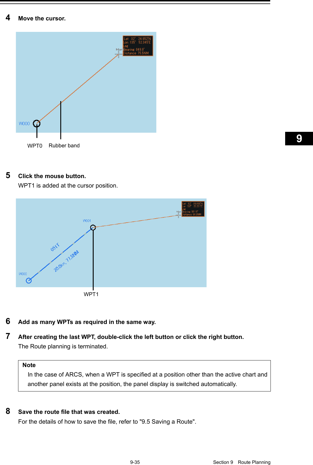
![Section 9 Route Planning 9-34 9.7.2 Creating a new route file by graphic editing 1 Click on the [New] button on the Route Planning bar. Or select the [New] button on the menu that is displayed by clicking on the Route Planning menu button. 2 Placing the cursor on the WPT0 position. The latitude and the longitude of the WPT are displayed near the cursor. 3 Click the mouse button. WPT0 is added.](https://usermanual.wiki/Japan-Radio-Co/NKE2632.Instruction-Manual-Funtion-Part-3/User-Guide-2791062-Page-48.png)
![Section 9 Route Planning 9-36 9.7.2.1 Creating a route by using EBL/VRM 1 Click on [Use EBL/VRM] on the [Edit] button to select it. The cursor changes to EBL/VRM. 2 Move the cursor to the position used as the mark (example: headland) and click on the position.](https://usermanual.wiki/Japan-Radio-Co/NKE2632.Instruction-Manual-Funtion-Part-3/User-Guide-2791062-Page-50.png)
![9-37 Section 9 Route Planning 1 2 3 4 5 6 7 8 9 10 11 12 13 14 15 16 17 18 19 20 21 22 23 24 25 26 27 3 Move the cursor and determine the WPT position while checking the bearing from the position used as the mark. The latitude/longitude is displayed next to the cursor. 4 Click the mouse button. WPT0 is created. 5 Add as many WPTs as required in the same way. Memo When EBL/VRM is not used for creation of the next WPT, clear the item by clicking on [Use EBL/VRM].](https://usermanual.wiki/Japan-Radio-Co/NKE2632.Instruction-Manual-Funtion-Part-3/User-Guide-2791062-Page-51.png)
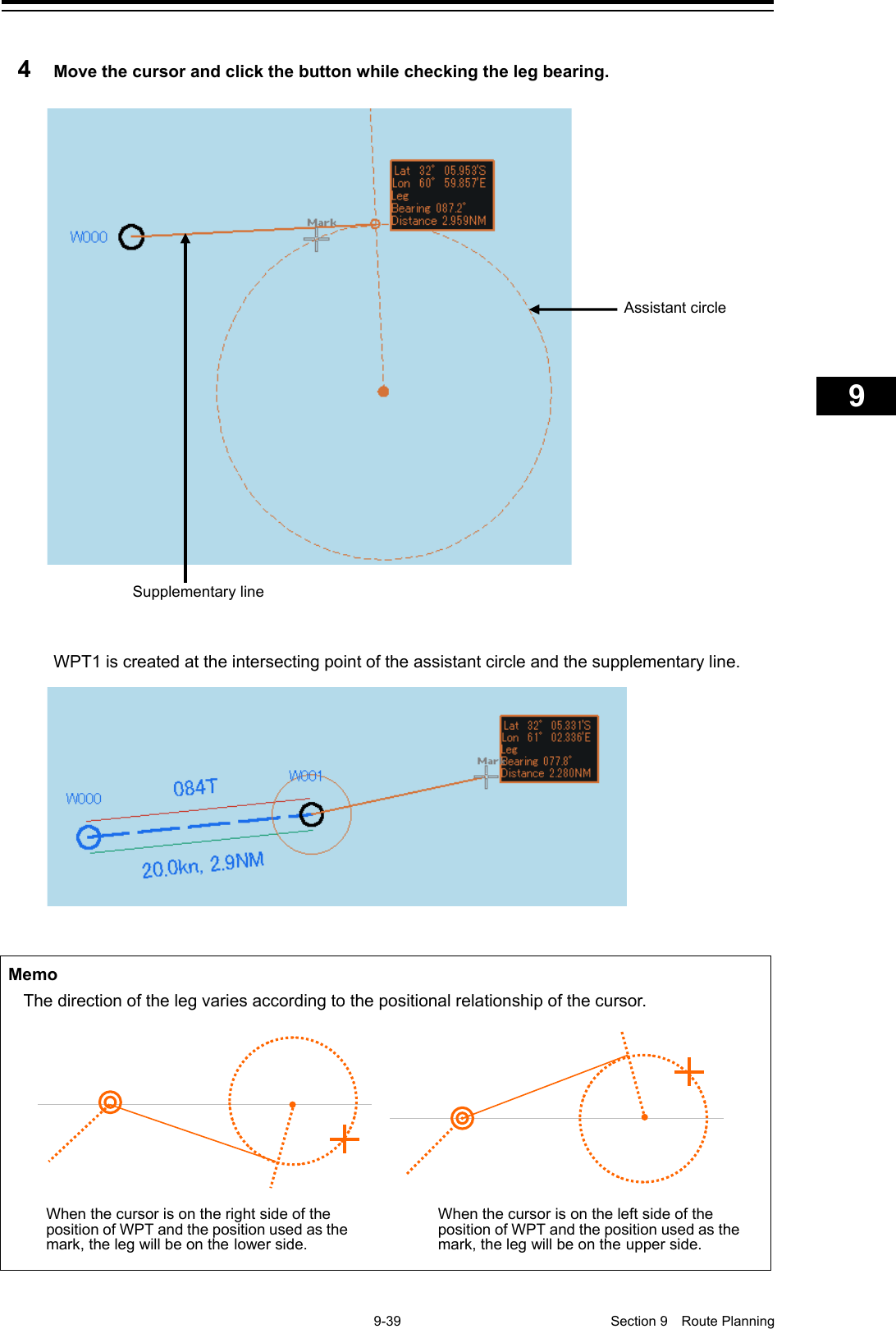
![Section 9 Route Planning 9-38 6 After creating the last WPT, double click the left button or click the right button. The Route planning is terminated. 9.7.2.2 Creating a route by using the assistant circle function A route can be created by using an assistant circle (supplementary line). The assistant circle function adds WPT at the position where the mark such as headland and the leg intersects at right angles. When the position that is used as the mark is determined and the cursor is moved to the position, WPT is added at the position where the leg and the position intersect at right angles. 1 Select the [Use Assistant circle] check box of the [Edit] button. 2 Move the cursor to any position and click the left button. WPT0 is created. 3 Move the cursor to the position as the mark (example, headland) and click the button. Supplementary line](https://usermanual.wiki/Japan-Radio-Co/NKE2632.Instruction-Manual-Funtion-Part-3/User-Guide-2791062-Page-52.png)