Japan Radio Co NKE2632 Solid State S-Band Marine Radar User Manual Instruction Manual Operation Part 1
Japan Radio Co Ltd. Solid State S-Band Marine Radar Instruction Manual Operation Part 1
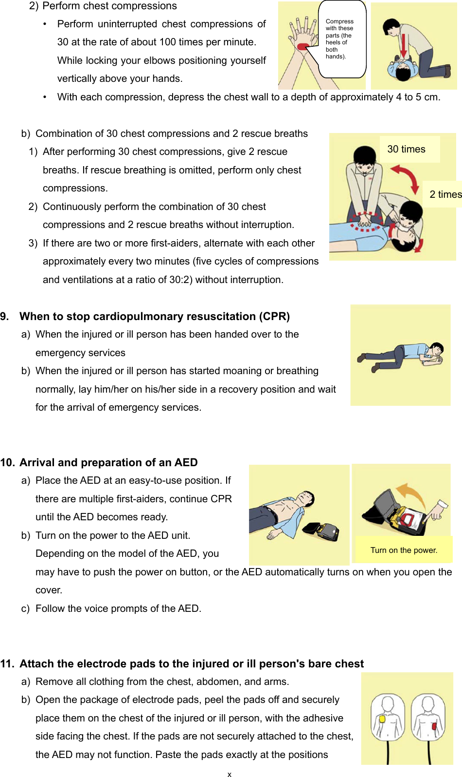
Contents
- 1. Installation Manual Part 1
- 2. Installation Manual Part 2
- 3. Installation Manual Part 3
- 4. Installation Manual Part 4
- 5. Installation Manual Part 5
- 6. Installation Manual Part 6
- 7. Installation Manual Part 7
- 8. Installation Manual Part 8
- 9. Installation Manual Part 9
- 10. Installation Manual Part 10
- 11. Installation Manual Part 11
- 12. Instruction Manual Operation Part 1
- 13. Instruction Manual Operation Part 2
- 14. Instruction Manual Operation Part 3
- 15. Instruction Manual Operation Part 4
- 16. Instruction Manual Funtion Part 1
- 17. Instruction Manual Funtion Part 2
- 18. Instruction Manual Funtion Part 3
- 19. Instruction Manual Funtion Part 4
- 20. Instruction Manual Funtion Part 5
- 21. Instruction Manual Funtion Part 6
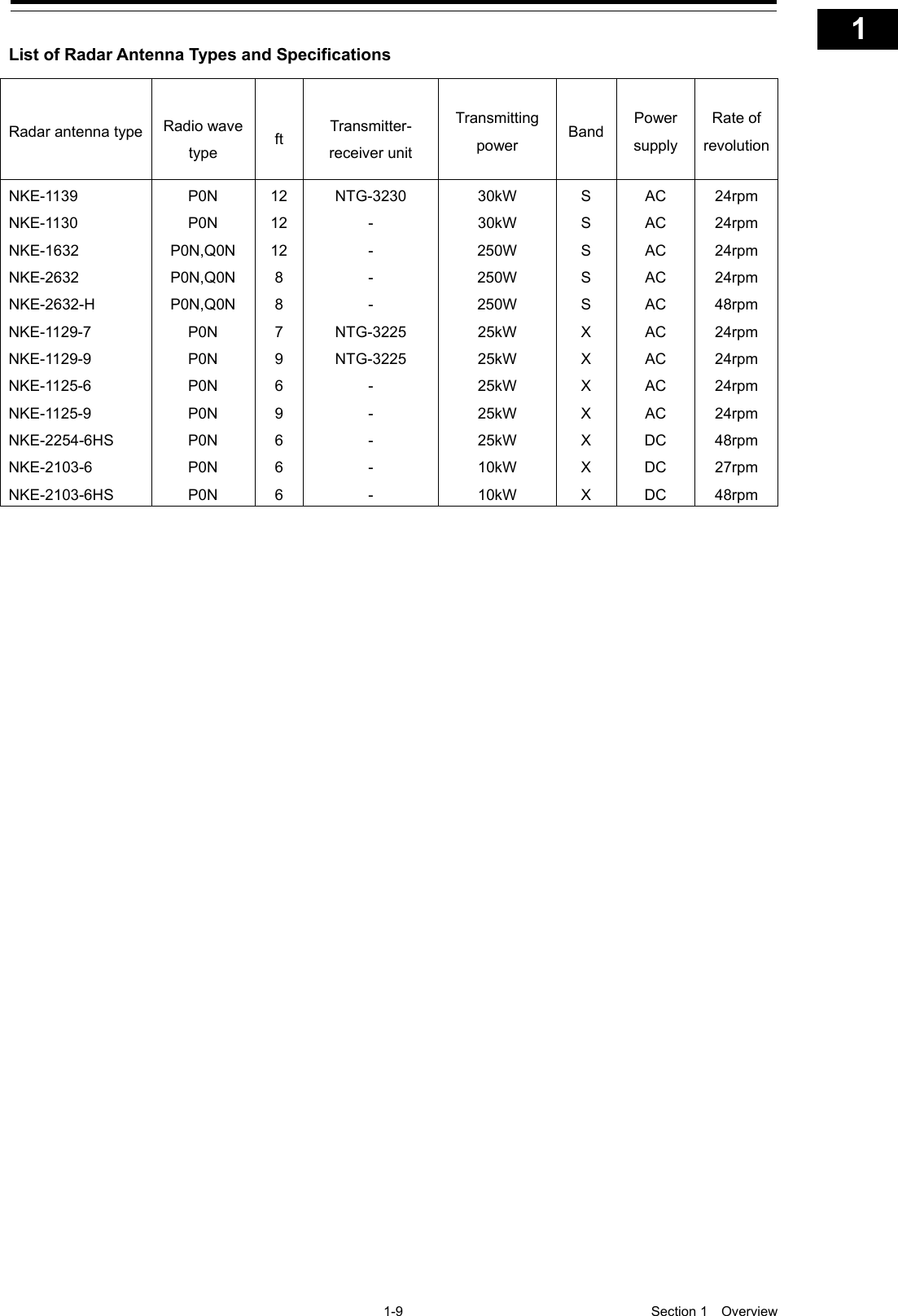
Instruction Manual Operation Part 1
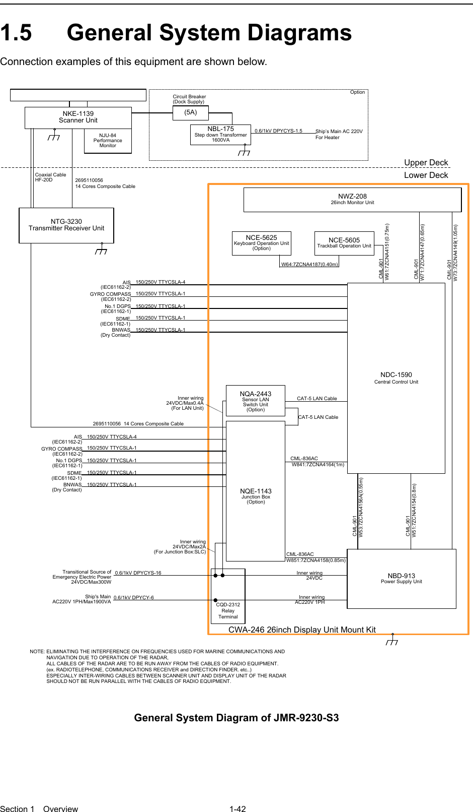
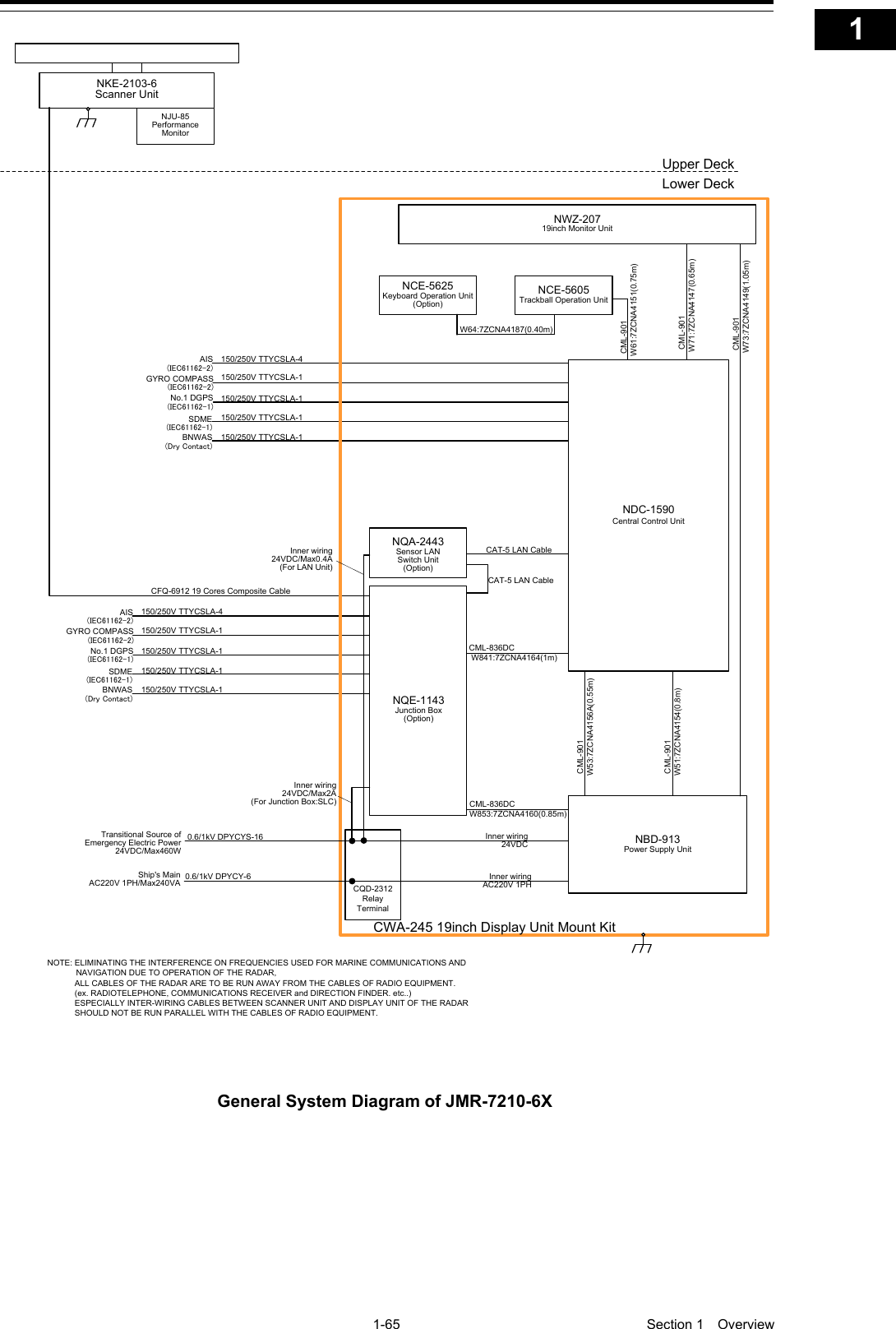
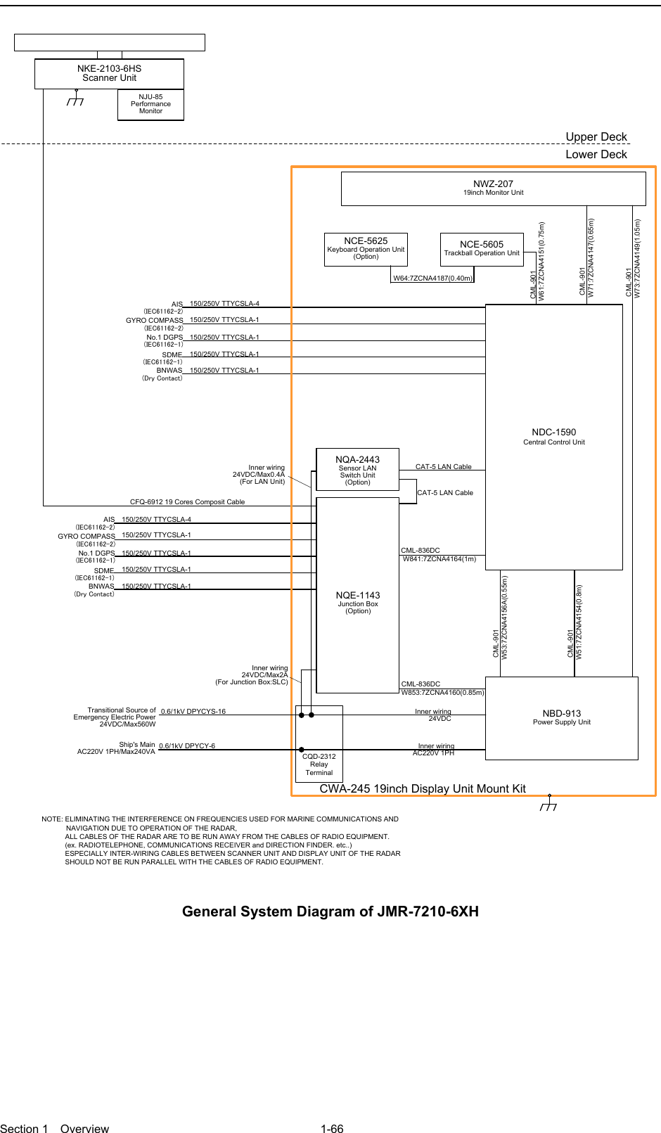
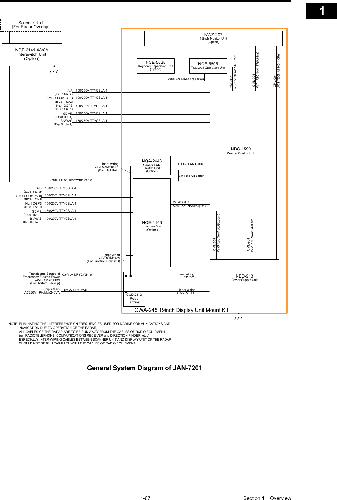
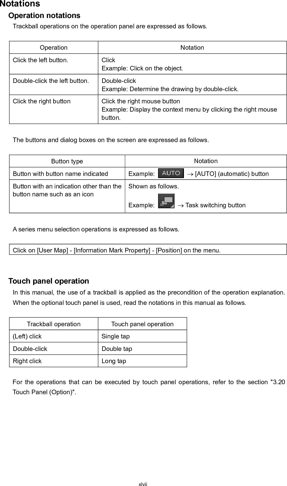
![Overview 1 Name and Function of Each Unit 2 Common Basic Operations 3 Range and Bearing Measurement Methods 4 Basic Operation of the Radar 5 Target Tracking and AIS 6 True and False Echoes on Display 7 Functions of the ECDIS (Option) 8 Route Planning 9 Route Monitoring 10 Monitoring a Dragging Anchor 11 Automatic Sailing (Option) 12 Operating a Chart (Option) 13 Creating a User Map/ Updating a Chart Manually 14 Logbook 15 Setting Up Screen View 16 Setting Up Alerts 17 Setting Up the Operation Mode 18 Adjusting and Setting Up Equipment (for Services) 19 Playing Back Data Recorded During Navigation [Playback] 20 Maintenance & Inspection 21 Failures and After-Sale Services 22 About Disposal 23 Specifications 24 Radar Antenna Block Diagrams APP A Alert List APP B Setting the Interswitch APP C Menu List and Materials APP D JMR-7230-S3/S JMR-7225-7X3/9X3/6X/9X/6XH JMR-7210-6X/6XH JMR-7272-S JMR-7282-S/SH JMR-9230-S3/S JMR-9225-7X3/9X3/6X/9X/6XH JMR-9210-6X/6XH JMR-9272-S JMR-9282-S/SH Marine Radar Equipment Instruction Manual <Basic Operation>](https://usermanual.wiki/Japan-Radio-Co/NKE2632.Instruction-Manual-Operation-Part-1/User-Guide-2791056-Page-1.png)

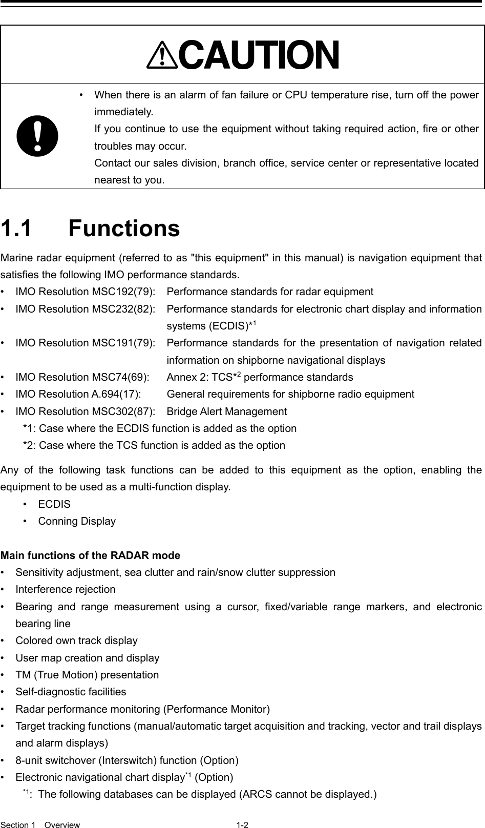
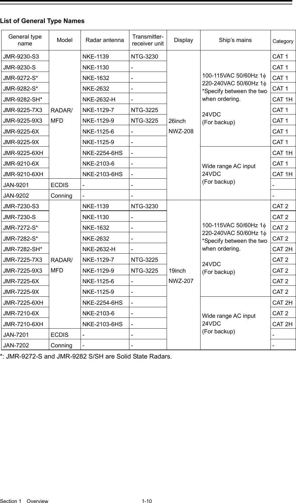
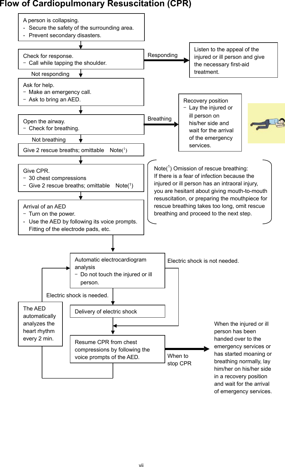
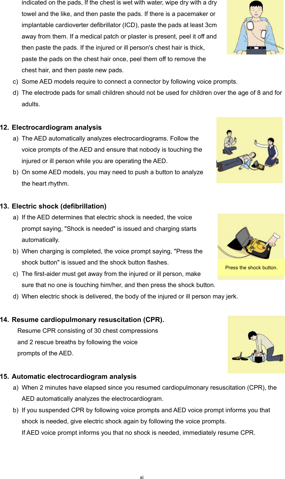
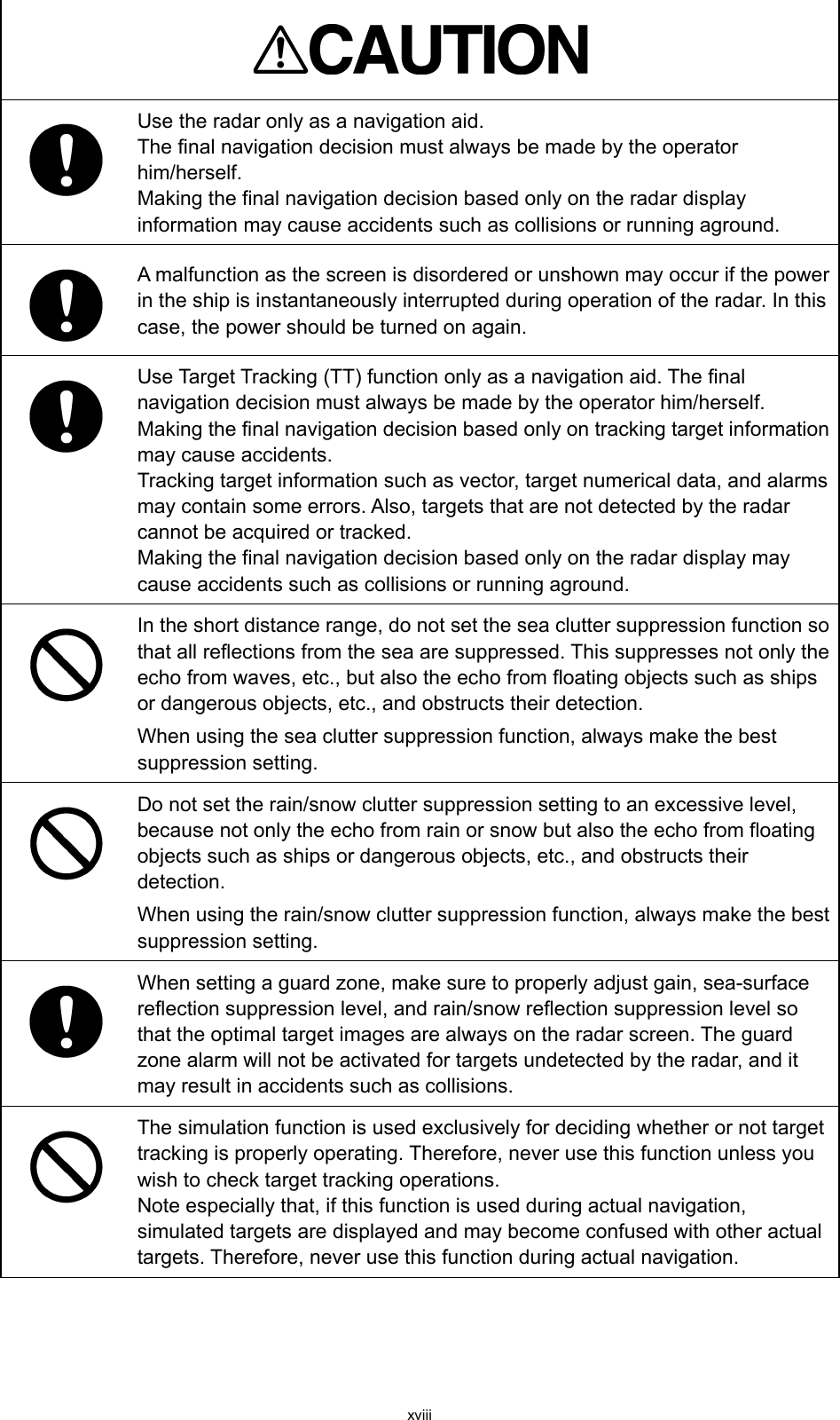
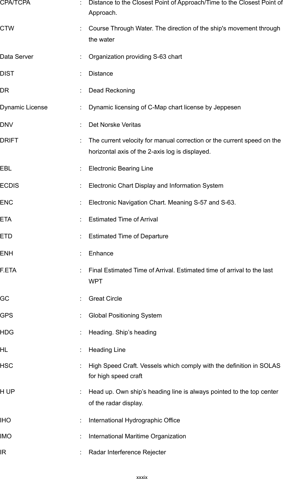
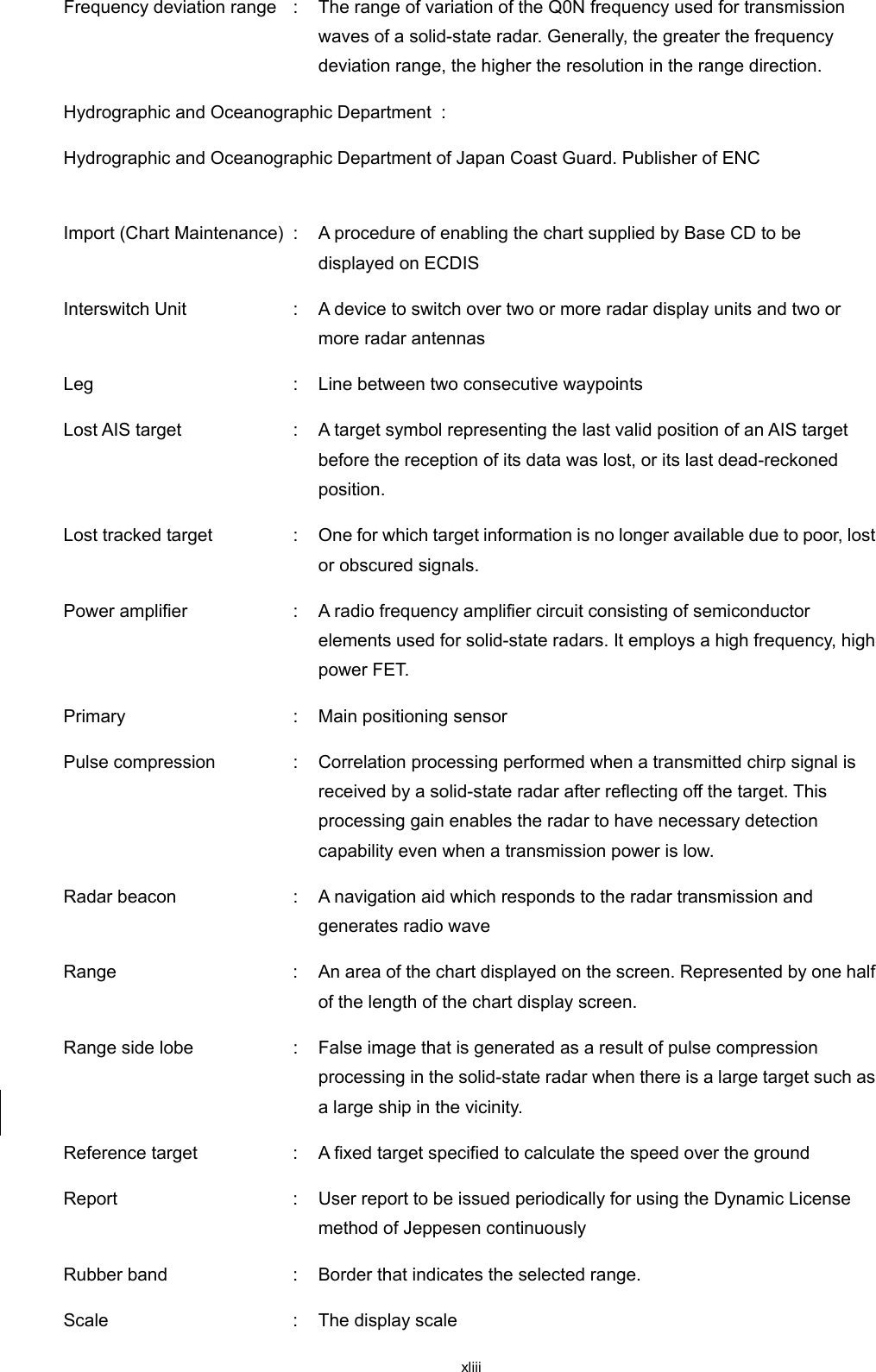
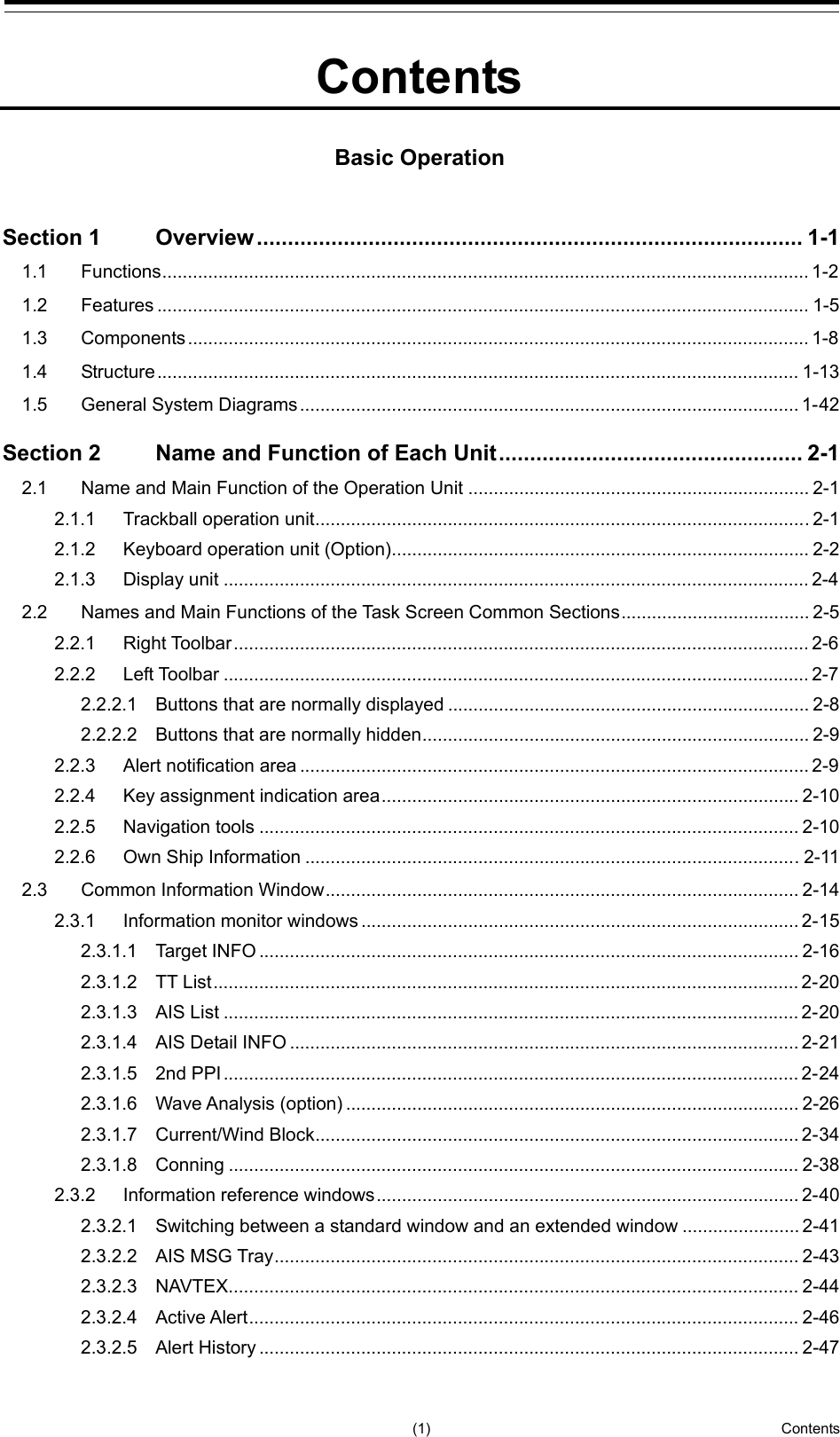
![vi Treatment to Give When the Patient Has a Pulse Beating but Has Ceased to Breathe ∗ Performing mouth-to-mouth artificial respiration (1) Bend the patient's face backward until it is directed to look back. (A pillow may be placed under the neck.) (2) Pull up the lower jaw to open up the airway. (To spread the airway) (3) Pinching the patient's nose, breathe deeply and blow your breath into the patient's mouth strongly, with care to close it completely. Then, move your mouth away and take a deep breath, and blow into his or her mouth. Repeat blowing at 10 to 15 times a minute (always with the patient's nostrils closed). (4) Continue artificial respiration until natural respiration is restored. (5) If the patient's mouth won't open easily, insert a pipe, such as one made of rubber or vinyl, into either nostril. Then, take a deep breath and blow into the nostril through the pipe, with the other nostril and the mouth completely closed. (6) The patient may stand up abruptly upon recovering consciousness. Keep the patient lying calmly, giving him or her coffee, tea or any other hot drink (but not alcoholic drink) to keep him or her warm. Mouth-to-mouth artificial respiration with the patient's head lifted [1] (1) Lift the back part of the patient's head. Support the forehead with one of your hand and the neck with the other hand.→ [1]. Many patients will have their airways opened by lifting their head in this way to ease mouth-to-mouth artificial respiration. [2] (2) Closing the patient's mouth with your mouth, press your cheek against the patient's nose→ [2]. Alternatively, hold the patient's nose with your finger to prevent air leak → [3]. [3] (3) Blowing air into the patient's lungs. Blow air into the patient's lungs until chest is seen to rise. The first 10 breaths must be blown as fast as possible. Fig. 1 Mouth-to-mouth artificial respiration](https://usermanual.wiki/Japan-Radio-Co/NKE2632.Instruction-Manual-Operation-Part-1/User-Guide-2791056-Page-6.png)

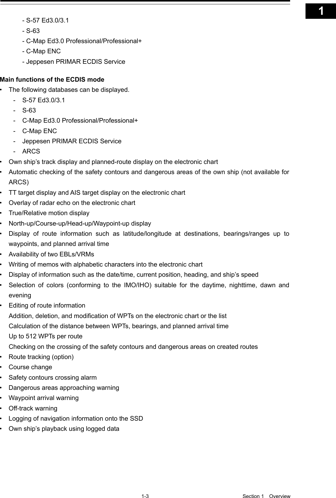
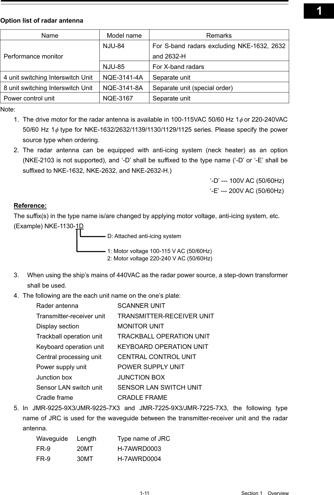
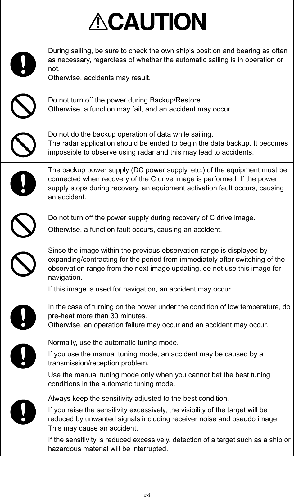
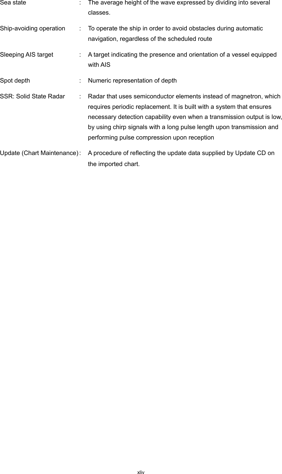
![xvi When cleaning the display screen, do not wipe it too strongly with a dry cloth. Also, do not use gasoline or thinner to clean the screen. Failure will result in damage to the screen surface. Do not change Initial Level/Area Offset unless absolutely necessary. Incorrect adjustment will result in deletion of nearby target images and thus collisions may occur resulting in death or serious injuries. Confirm computer virus does not exist in USB flash memory beforehand when reading and writing of the file by using USB flash memory. Influences other equipment when the display unit is infected with the virus, and it may cause a breakdown. Do not remove USB flash memory while the access lamp (in USB flash drive) is flashing. Data may be damaged when the USB flash memory is inserted or removed while accessing it, and it may cause a breakdown. Do not place a glass or cup containing water, etc., or a small metal object on this equipment. If water or such object gets inside, a fire, an electric shock, or a malfunction may occur. In case water or a metal object gets inside the equipment, turn off the power immediately, unplug the power supply cable from an electric outlet, and contact our head office, or a nearby branch or local office to request servicing. Keeping the equipment in operation under such condition may cause a fire, an electric shock or a malfunction. In case you find smoke, unusual odor or extreme high heat coming from the equipment, turn off the power immediately, unplug the power supply cable from an electric outlet, and contact our head office, or a nearby branch or local office to request servicing. Keeping the equipment in operation under such condition may cause a fire or an electric shock. Do not use the offset function during navigation. If the equipment is used with the offset value entered as the own ship position (deviated from the actual position), accidents may result. When the offset values are entered, the [Offset] badge is displayed at the position display on the Own Ship Information. Check the indication, and cancel the offset function if necessary. Also, the message "Position Shift" is displayed in the message display area.](https://usermanual.wiki/Japan-Radio-Co/NKE2632.Instruction-Manual-Operation-Part-1/User-Guide-2791056-Page-16.png)
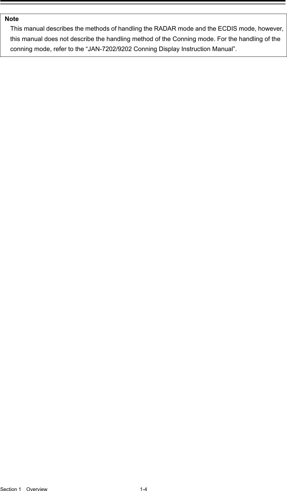
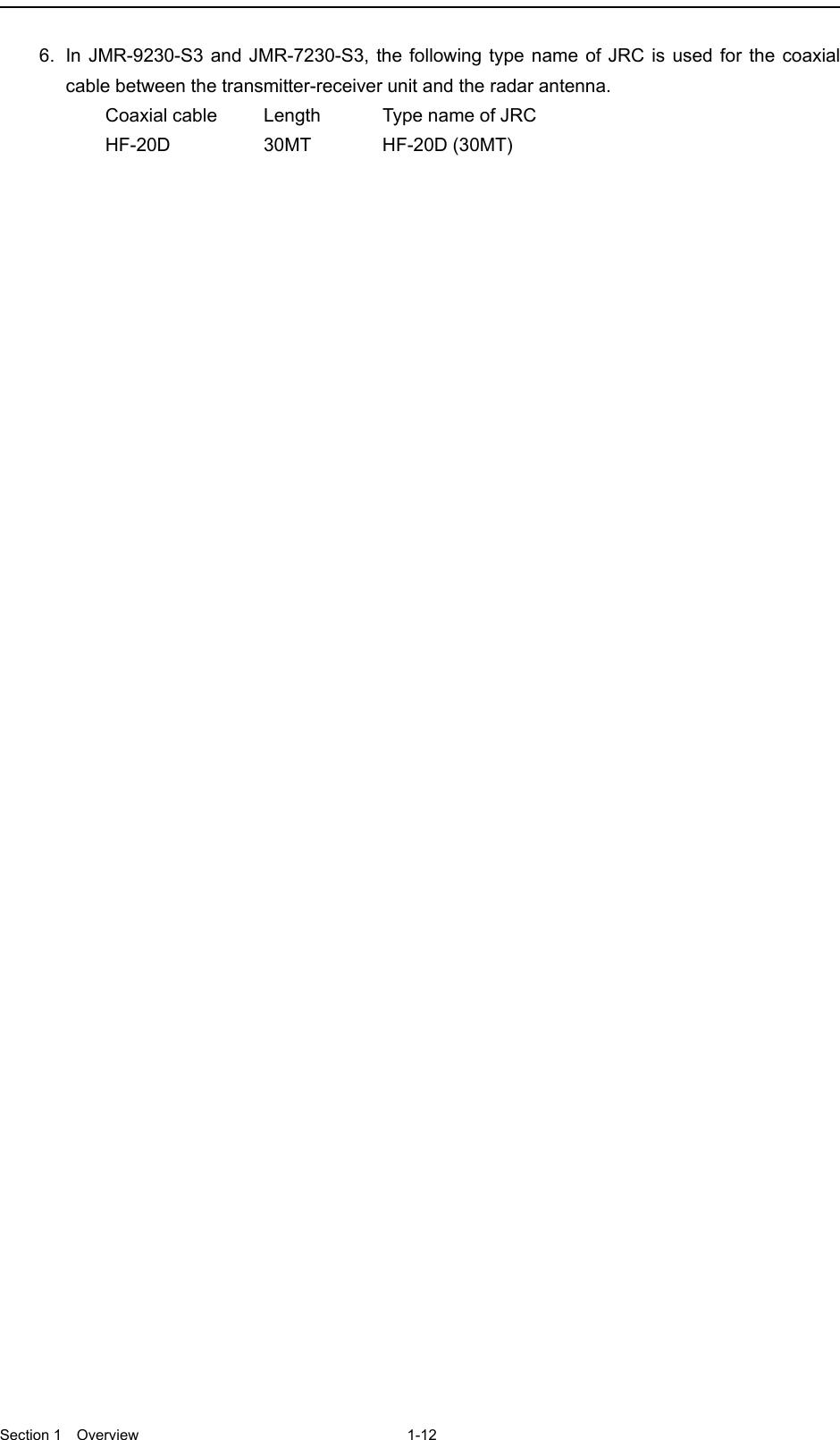
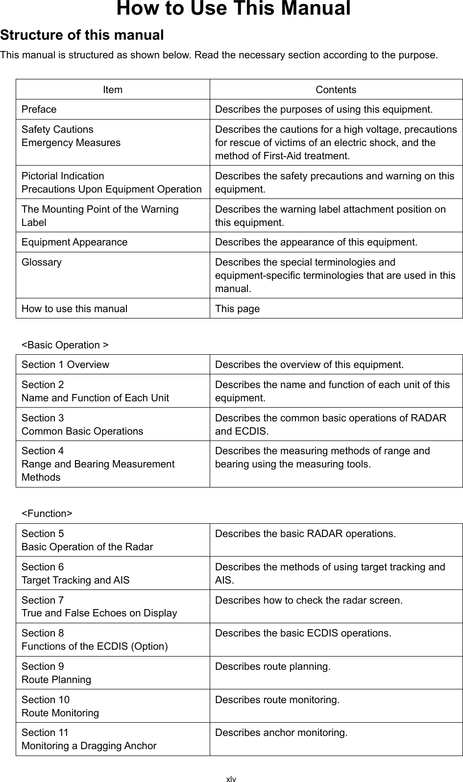
![xvii Before starting automatic sailing, be sure to check the safety of the route and the safety when crossing safety contour. Otherwise, accidents may result. If the own ship has arrived at the boundary of a WPT during automatic sailing, be sure to check the safety and perform turning manually by the operator him/herself. Otherwise, the ship keeps the course with the leg bearing, and accidents may result. Input the ship’s parameter accurately according to the specification of the ship. Otherwise, accidents may result. Change of the color of the Day/Night button, particularly the use of the [Night] color, may interfere with the recognition of display information. When moving the dialog box, move to the position that does not cover the operation area. If the dialog box covers the operation area, it may interfere the recognition of the display information. Do not apply strong shock to the coaxial cable by striking it with a tool or hammering it. Otherwise, an open circuit failure may result. Do not place anything heavy on the coaxial cable. Otherwise, an open circuit failure may result. Do not twist or pull the coaxial cable. Otherwise, an open circuit failure may result.](https://usermanual.wiki/Japan-Radio-Co/NKE2632.Instruction-Manual-Operation-Part-1/User-Guide-2791056-Page-17.png)

![xlvi <Function> Section 12 Automatic Sailing (Option) Describes automatic sailing. Section 13 Operating a Chart (Option) Describes chart operations. Section 14 Creating a User Map/ Updating a Chart Describes creation of user maps and automatic chart updating. Section 15 Logbook Describes the logbook. Section 16 Setting Up Screen View Describes the detail setting of screen display. <Reference> Section 17 Setting Up Alerts Describes the alert detail setting for avoiding dangers. Section 18 Setting Up the Operation Mode Describes the detail setting of the operation modes of this equipment. Section 19 Adjusting and Setting Up Equipment (for Services) Describes the equipment adjustments and setting that are performed by the maintenance engineers. Section 20 Playing Back Data Recorded During Navigation [Playback] Describes playback of the data recorded during sailing. Section 21 Maintenance & Inspection Describes the maintenance and inspection of this equipment. Section 22 Failures and After-Sale Services Describes the failure handling measures and aftercare services of this equipment. Section 23 About Disposal Describes the cautions on disposing of this equipment. Section 24 Specifications Describes the specification of this equipment. Appendix A Radar Antenna Block Diagrams Describes various block diagrams, connection diagrams, schematic diagrams, and setting tables. Appendix B Alert List Describes the alert list. Appendix C Setting the Interswitch Describes the interswitch setting. Appendix D Menu List and Materials Describes the materials such as the menu list.](https://usermanual.wiki/Japan-Radio-Co/NKE2632.Instruction-Manual-Operation-Part-1/User-Guide-2791056-Page-46.png)
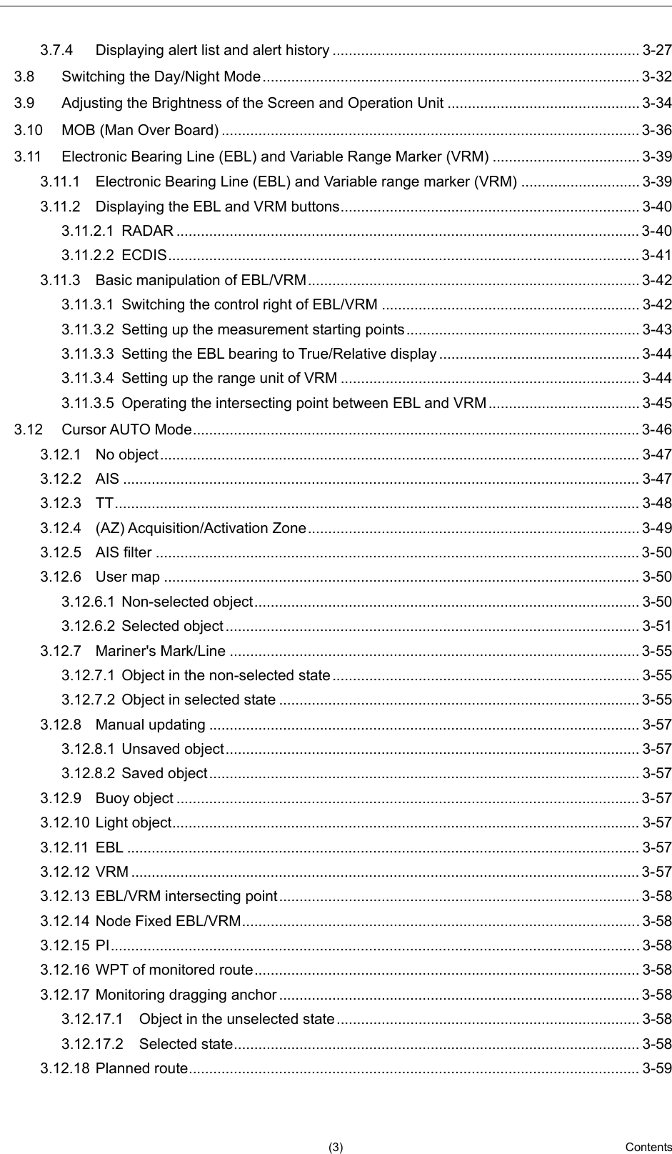
![xlvii Notations Operation notations Trackball operations on the operation panel are expressed as follows. Operation Notation Click the left button. Click Example: Click on the object. Double-click the left button. Double-click Example: Determine the drawing by double-click. Click the right button Click the right mouse button Example: Display the context menu by clicking the right mouse button. The buttons and dialog boxes on the screen are expressed as follows. Button type Notation Button with button name indicated Example: → [AUTO] (automatic) button Button with an indication other than the button name such as an icon Shown as follows. Example: → Task switching button A series menu selection operations is expressed as follows. Click on [User Map] - [Information Mark Property] - [Position] on the menu. Touch panel operation In this manual, the use of a trackball is applied as the precondition of the operation explanation. When the optional touch panel is used, read the notations in this manual as follows. Trackball operation Touch panel operation (Left) click Single tap Double-click Double tap Right click Long tap For the operations that can be executed by touch panel operations, refer to the section "3.20 Touch Panel (Option)".](https://usermanual.wiki/Japan-Radio-Co/NKE2632.Instruction-Manual-Operation-Part-1/User-Guide-2791056-Page-47.png)
![Contents (4) 3.13 Saving the screen that is currently displayed...................................................................... 3-61 3.14 [MULTI] Dial ......................................................................................................................... 3-62 3.14.1 Functions of [MULTI] dial ............................................................................................ 3-62 3.14.2 Functions assigned to [MULTI] dial ............................................................................. 3-62 3.14.2.1 Displaying a screen for setting the function that is assigned ............................... 3-62 3.14.2.2 Changing the function that is assigned ................................................................ 3-62 3.15 Basic Operations of the Software Keyboard ....................................................................... 3-64 3.15.1 Starting a software keyboard ...................................................................................... 3-64 3.15.2 Name and function of each section of the keyboard .................................................. 3-65 3.15.3 Numeric value input example ..................................................................................... 3-68 3.15.4 Character input example ............................................................................................. 3-70 3.16 Setting a Date and a Time (Calendar Operation) ............................................................... 3-73 3.16.1 Details and usage of a calendar picker and a time picker .......................................... 3-74 3.16.1.1 Details of a calendar ............................................................................................. 3-74 3.16.1.2 How to use a calendar .......................................................................................... 3-75 3.17 Help ..................................................................................................................................... 3-76 3.18 Password Input ................................................................................................................... 3-80 3.19 Managing Files with File Manager ...................................................................................... 3-82 3.19.1 Displaying the "File Manager" dialog box ................................................................... 3-82 3.19.2 File management ........................................................................................................ 3-83 3.19.3 Loading and saving files ............................................................................................. 3-86 3.19.3.1 Loading files ......................................................................................................... 3-86 3.19.3.2 Unloading data (clearing data from the data screen) ........................................... 3-88 3.19.3.3 Saving files ........................................................................................................... 3-89 3.20 Touch Panel (Option) .......................................................................................................... 3-90 3.21 Returning to a Task Menu by Ending the Operation ........................................................... 3-91 3.22 Terminating this equipment ................................................................................................. 3-93 3.23 Using a DVD Drive .............................................................................................................. 3-94 Section 4 Range and Bearing Measurement Methods ................................ 4-1 4.1 List of Measuring Tools ......................................................................................................... 4-1 4.2 Target Position ...................................................................................................................... 4-2 4.3 Using the Cross-hair Cursor.................................................................................................. 4-3 4.3.1 Cursor readout information area display position ......................................................... 4-3 4.3.1.1 RADAR ................................................................................................................... 4-3 4.3.1.2 ECDIS ..................................................................................................................... 4-4 4.3.2 Measuring the bearing and the range from the own ship’s position to the target by using the cross-hair cursor ........................................................................................... 4-5 4.3.2.1 Measuring by using the cursor information that is displayed by placing the cursor inside of PPI (RADAR only) ......................................................................... 4-5 4.3.2.2 Measuring by using the "Cursor readout" dialog .................................................... 4-6 4.3.2.3 Switching the cursor bearing between True/Relative ............................................. 4-7](https://usermanual.wiki/Japan-Radio-Co/NKE2632.Instruction-Manual-Operation-Part-1/User-Guide-2791056-Page-52.png)
![(5) Contents 2 3 4 5 6 7 8 9 10 11 12 13 14 15 16 17 18 19 20 21 22 23 24 25 26 27 4.3.2.4 Switching the cursor range unit .............................................................................. 4-7 4.4 Using the Range Rings ......................................................................................................... 4-8 4.5 Using the Electronic Bearing Line (EBL) and Variable Range Marker (VRM) .................... 4-10 4.5.1 Measuring a range and a bearing with EBL and VRM ............................................... 4-10 4.5.1.1 Measuring in the trackball operation unit .............................................................. 4-10 4.5.1.2 Measuring with the [EBL] or [VRM] dial on the keyboard operation unit .............. 4-11 4.5.2 Measuring between arbitrary two points ..................................................................... 4-14 4.5.3 Manipulating EBL/VRM with the context menu (ECDIS only) .................................... 4-16 4.5.3.1 Manipulating EBL/VRM with [Dropped EBL/VRM] - [Make EBL1/VRM1] or [Make EBL2/VRM2] .............................................................................................. 4-17 4.5.3.2 Manipulating EBL with [Dropped EBL/VRM] - [Make EBL1] or [Make EBL2] ...... 4-18 4.5.3.3 Manipulating VRM with [Dropped EBL/VRM] - [Make VRM1] or [Make VRM2] ... 4-19 4.5.3.4 Manipulating EBL/VRM with [Dropped EBL/VRM] - [Move base point of EBL1/VRM1] or [Move base point of EBL2/VRM2] .............................................. 4-19 4.5.3.5 Manipulating EBL/VRM with [CCRP EBL/VRM] - [Make EBL1/VRM1] or [Make EBL2/VRM2] .............................................................................................. 4-20 4.5.3.6 Manipulating EBL with [CCRP EBL/VRM] - [Make EBL1] or [Make EBL2] .......... 4-21 4.5.3.7 Manipulating VRM with [CCRP EBL/VRM] - [Make VRM1] or [Make VRM2] ...... 4-21 4.6 Using Parallel Index Lines (PI) ............................................................................................ 4-22 4.6.1 Description of a parallel index line .............................................................................. 4-22 4.6.2 Displaying parallel index lines ..................................................................................... 4-22 4.6.2.1 Displaying parallel index lines in the trackball operation unit ............................... 4-22 4.6.2.2 Displaying parallel index lines in the keyboard operation unit .............................. 4-23 4.6.2.3 Description of the "PI Menu" dialog ...................................................................... 4-24 4.6.3 Setting all the parallel index lines concurrently (All mode) ......................................... 4-28 4.6.3.1 Changing the bearing/interval of parallel index lines in the trackball operation unit (All mode) ...................................................................................................... 4-30 4.6.4 Setting parallel index lines individually (Individual mode) ........................................... 4-31 4.6.4.1 Changing the bearing/interval/end point of parallel index lines in the trackball operation unit (Individual mode) ........................................................................... 4-34 4.6.5 Displaying lines at equal interval on the left and right sides of the own ship’s position (Track mode) ................................................................................................. 4-35 4.6.5.1 Changing the bearing/interval of parallel index lines with the trackball (Track mode) .................................................................................................................... 4-37 4.6.6 Displaying two intersecting lines (Equiangular mode) ................................................ 4-38 4.6.6.1 Changing the bearing of two intersecting lines in the trackball operation unit (Equiangular mode) .............................................................................................. 4-39 4.6.7 Setting parallel index lines in the keyboard operation unit ......................................... 4-40 4.6.7.1 Operation in All mode ........................................................................................... 4-40 4.6.7.2 Operation in Individual mode ................................................................................ 4-41 4.6.7.3 Operation in Track mode ...................................................................................... 4-41 4.6.7.4 Operation in Equiangular mode ............................................................................ 4-42 4.7 Using the EBL Maneuver .................................................................................................... 4-43](https://usermanual.wiki/Japan-Radio-Co/NKE2632.Instruction-Manual-Operation-Part-1/User-Guide-2791056-Page-53.png)
![Contents (6) 4.7.1 Displaying the EBL Maneuver Setting dialog box ....................................................... 4-43 4.7.2 Clearing the display of maneuver curve ..................................................................... 4-44 4.7.3 Setting the creation conditions of the EBL Maneuver ................................................. 4-44 4.7.4 Creating an EBL maneuver curve ............................................................................... 4-45 4.8 Connecting Own Ship and the Specified Fixed Position with EBL and the VRM Marker (Node Fixed EBL/VRM Function) ................................................................................................... 4-47 4.8.1 Displaying the "Node Fixed EBL/VRM" dialog box ..................................................... 4-47 4.8.2 Description of "Node Fixed EBL/VRM" dialog box ..................................................... 4-48 4.8.3 Creating a new Node Fixed EBL/VRM ....................................................................... 4-48 4.8.4 Cancelling the Node Fixed EBL/VRM function ........................................................... 4-49 4.9 Measuring the Own Ship’s Position Manually (LOPs Fixing Function of Manual position fix)4-50 4.9.1 Displaying the "Manual position fix" dialog box .......................................................... 4-50 4.9.2 Description of the "LOPs Fixing" tab of the "Manual position fix" dialog box ............. 4-51 4.9.3 Creating LOP .............................................................................................................. 4-53 4.9.3.1 Creating bearing LOP ........................................................................................... 4-53 4.9.3.2 Creating distance LOP ......................................................................................... 4-55 4.9.4 Measuring the own ship’s position in cross bearing fix ............................................... 4-56 4.9.4.1 Automatic position fixing ....................................................................................... 4-57 4.9.4.2 Automatic offset .................................................................................................... 4-58 4.9.4.3 Manual position fixing ........................................................................................... 4-60 4.9.4.4 When there are three or more LOPs or TPLs ...................................................... 4-61 4.9.4.5 Setting a plotted position ...................................................................................... 4-63 4.9.5 Measuring the own ship’s position with Running Fix .................................................. 4-64 4.9.6 Measuring the own ship’s position with other methods .............................................. 4-68 4.10 Offsetting the Own Ship’s Position Manually (Position Offset Function of Manual position fix)4-69 4.10.1 Displaying the "Manual position fix" dialog box .......................................................... 4-69 4.10.2 Description of the [Position Offset] tab of the "Manual position fix" dialog box .......... 4-71 4.10.3 Setting the offset amount that is input in the "Enter Offset" dialog as the offset position ........................................................................................................................ 4-72 4.10.4 Setting the position on the chart on which the mouse button was clicked as the offset position .............................................................................................................. 4-73 4.10.5 Recording LOPs Fixing operation in the logbook ....................................................... 4-74 4.10.6 Offsetting the own ship position .................................................................................. 4-76](https://usermanual.wiki/Japan-Radio-Co/NKE2632.Instruction-Manual-Operation-Part-1/User-Guide-2791056-Page-54.png)