Japan Radio Co NKE2632 Solid State S-Band Marine Radar User Manual Installation Manual Part 11
Japan Radio Co Ltd. Solid State S-Band Marine Radar Installation Manual Part 11
Contents
- 1. Installation Manual Part 1
- 2. Installation Manual Part 2
- 3. Installation Manual Part 3
- 4. Installation Manual Part 4
- 5. Installation Manual Part 5
- 6. Installation Manual Part 6
- 7. Installation Manual Part 7
- 8. Installation Manual Part 8
- 9. Installation Manual Part 9
- 10. Installation Manual Part 10
- 11. Installation Manual Part 11
- 12. Instruction Manual Operation Part 1
- 13. Instruction Manual Operation Part 2
- 14. Instruction Manual Operation Part 3
- 15. Instruction Manual Operation Part 4
- 16. Instruction Manual Funtion Part 1
- 17. Instruction Manual Funtion Part 2
- 18. Instruction Manual Funtion Part 3
- 19. Instruction Manual Funtion Part 4
- 20. Instruction Manual Funtion Part 5
- 21. Instruction Manual Funtion Part 6
Installation Manual Part 11
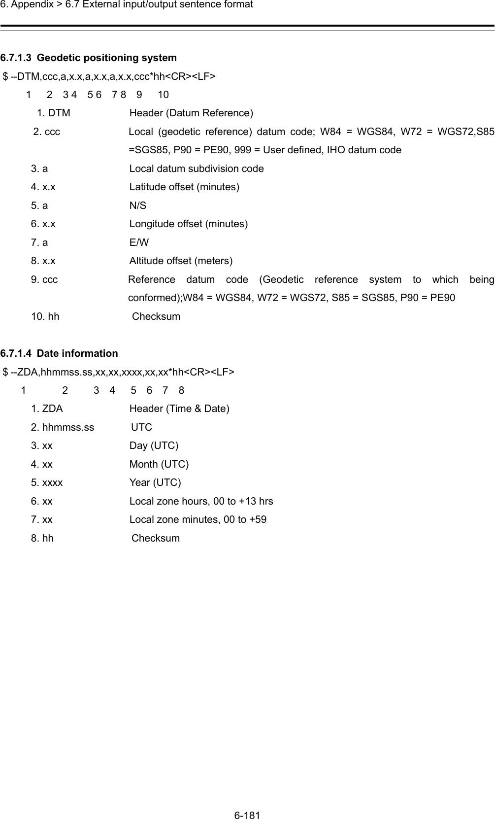
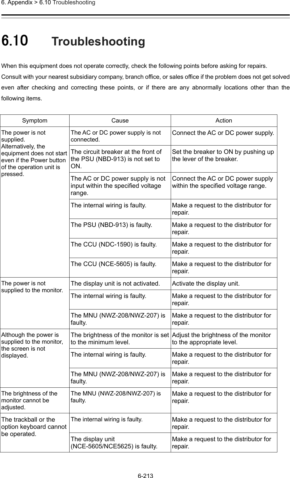
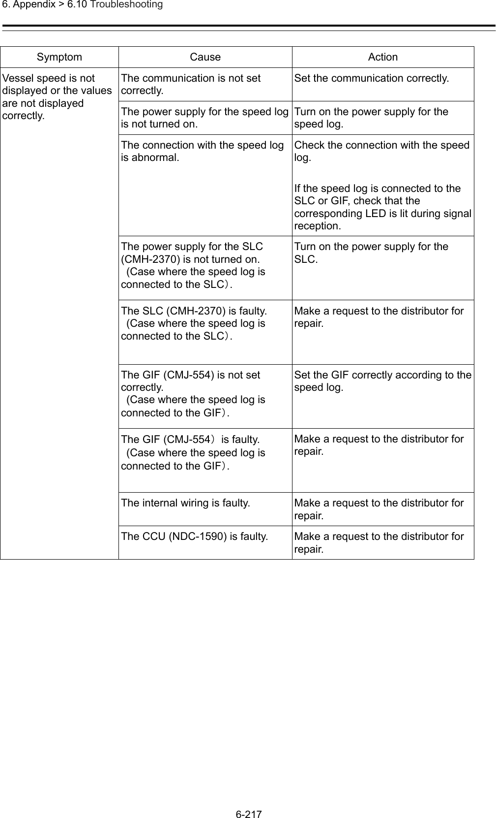
![6. Appendix > 6.6 Scanner Unit Interconnection Unit 6-176 6.6.13 NKE-1632 258396RF_ANTPM_OUTPERFORMANCE MONITOR ANTENNARED.TBLK.T 3.MV1.MU2.NC4.NC1.+12V2.GNDWHT.TU1V1UTHUVU1V1UTHUV2.NC4.NC1.S12.S23.S34.S45.S56.S63.M21.M15.M3MOTORB1011.+12V1.MNT-RX-P2.MNT-TX-P3.MNT-RX-N4.MNT-TX-N5.MNTEFAN1.+32V2.GND1. +32V2. GNDB2PS-VH1. +3.3V2. GND+3.3VGND2.RTNJ5105J5203J5201J5301J5901TB102OGM-300NE-6P-04CJ3505J2901J2902DATA I/FCPU JTAGFPGA JTAGJ29031.VD+2.VD-3.GND4.BP5.BZ6.GND7.TIY8.MTR_TRX-9.TIY_RTN10.MTR_TRX+11.GND12.GND13.MNT_TX+14.GND15.MNT_TX-16.PHZ17.GND18.PHA19.MNT_RX-20.PHB21.MNT_RX+22.GND23.GND24.MOT_TRX-25.C226.MOT_TRX+27.GND28.GND29.FAN_CNT030.PS_STATUS1.VD2.GND3.GND4.BP5.BZ6.GND7.TIY8.MTR_TRX-9.TIY_RTN10.MTR_TRX+11.GND12.GND13.MNT_TX+14.GND15.MNT_TX-16.PHZ17.GND18.PHA19.MNT_RX-20.PHB21.MNT_RX+22.GND23.GND24.MOT_TRX-25.C226.MOT_TRX+27.GND28.GND29.FAN_CNT030.PS_STATUSJ2501PV-3-TJ2502PV-3-TJ2503DF20F-30DP-1H(59)DF20F-30DP-1H(59)1.VD+2.VD-3.TRIG+4.TRIG-5.BP+6.BP-7.BZ+8.BZ-9.MTR+10.MTR-11.MTRG12. NC13. DC48V+TB101231-344/001-000 [WAGO]DF3A- 5P-2DSA3.MOT_TRX+4.MOT_TRX-5.GNDJ1501B4P-VH(LF,SN)J150553426-0510(L angle)J1504B3P-VH(LF,SN) B3P5-VH(LF,SN)J1503B06BOXASK-1(LF,SN)J1301P1301J4301P4301P3104P3102P3505P5301P5201 P2501P2502P5105P1505SC02B-J42SK-GHXPR SC02B-J42SK-GHXPRP1501P1504S2B-XH-A14. DC48VGJ3102P0B-R-35J3104P0B-R-35W2047ZCRD1669*W1037ZCRD1668* W2037ZCRD1675W1027ZCRD1667*W2017ZCRD1676*W2027ZCRD1677*W1047ZCRD1671*W17ZCRD1680*W302W3017ZCRD1692*W3037ZCRD1694*W1017ZCRD1673*W5017ZCRD1674*W4017ZCRD1682*J1502“*” means revision of the specfication document.7ZCRD1693*RED.TBLK.TRED.TRED.TWHT.T(TRANSDUCER)(ROTARY JOINT)(N type connector)](https://usermanual.wiki/Japan-Radio-Co/NKE2632.Installation-Manual-Part-11/User-Guide-2791044-Page-1.png)
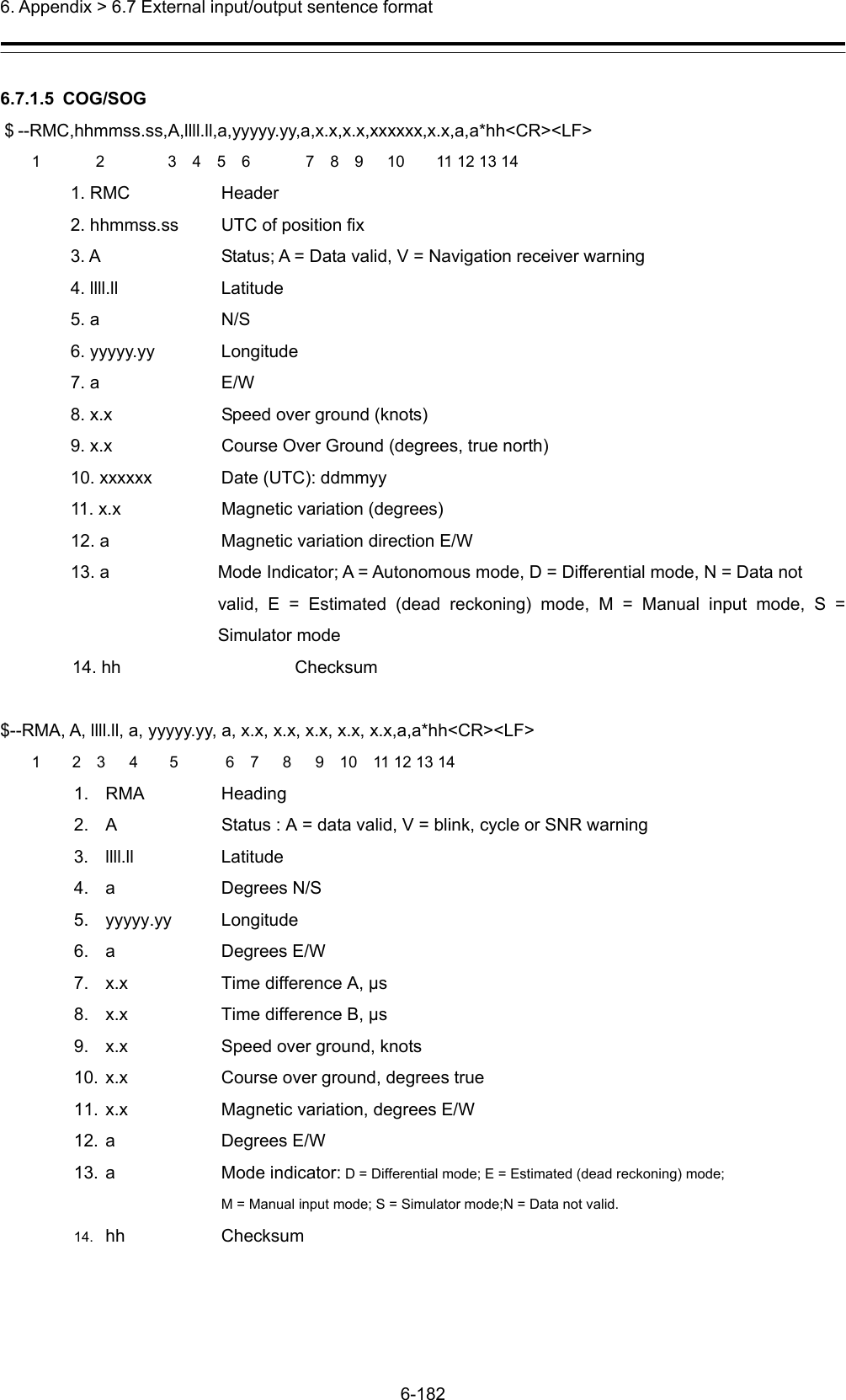
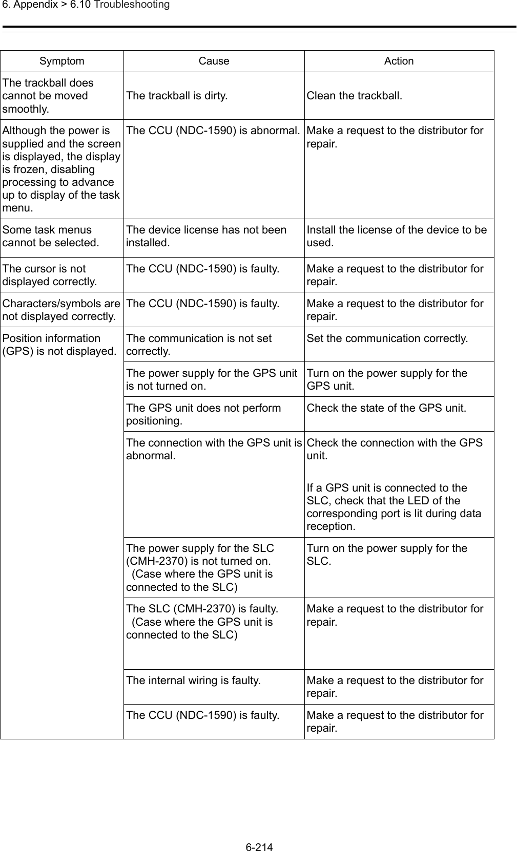
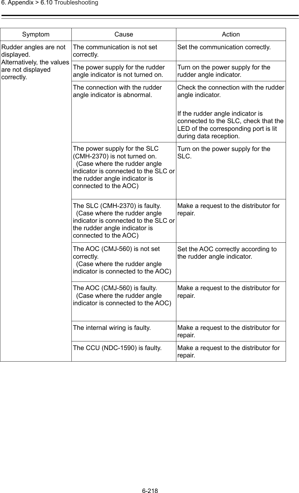
![6. Appendix > 6.6 Scanner Unit Interconnection Unit 6-177 6.6.14 NKE-2632/2632-H 258396REDBLKWHTBLUBLK(SHIELD)1.+12V2.C21.+12V2.RTN1.+12V2.RTN3.PHA4.PHB5.PHZ6.GNDIF_OUT(Rx)RF_ANTPM_OUTIF_IN(Tx)PERFORMANCE MONITOR ANTENNARED.TBLK.T1.R13.R22.NC3.MV1.MU2.NC4.NC1.+12V2.GNDWHT.TU1V1UTHUVU1V1UTHUV2.NC4.NC1.S12.S23.S34.S45.S56.S63.M21.M15.M3MOTORB1011.+12V1.MNT-RX-P2.MNT-TX-P3.MNT-RX-N4.MNT-TX-N5.MNTEFAN1.+32V2.GND1. +32V2. GNDB2PS-VH1. +3.3V2. GND+3.3VGND2.RTNJ5105J5101J5102J5203J5201J5103J5301J5901TB102OGM-300NE-6P-04CJ320127DP-LR-PS-1J320327DP-LR-PS-1J3206DF20F-10DP-1H(59)J3505J2901J2902DATA I/FCPU JTAGFPGA JTAGJ29031.VD+2.VD-3.GND4.BP5.BZ6.GND7.TIY8.MTR_TRX-9.TIY_RTN10.MTR_TRX+11.GND12.GND13.MNT_TX+14.GND15.MNT_TX-16.PHZ17.GND18.PHA19.MNT_RX-20.PHB21.MNT_RX+22.GND23.GND24.MOT_TRX-25.C226.MOT_TRX+27.GND28.GND29.FAN_CNT030.PS_STATUS1.VD2.GND3.GND4.BP5.BZ6.GND7.TIY8.MTR_TRX-9.TIY_RTN10.MTR_TRX+11.GND12.GND13.MNT_TX+14.GND15.MNT_TX-16.PHZ17.GND18.PHA19.MNT_RX-20.PHB21.MNT_RX+22.GND23.GND24.MOT_TRX-25.C226.MOT_TRX+27.GND28.GND29.FAN_CNT030.PS_STATUS1.GND2.RF_STC3.NC4.LO_MODE5.GND6.RF_GATE7.GND8.PM_MODE9.GND10.TX_MONIJ2303DF20F-10DP-1H(59)J2501PV-3-TJ2502PV-3-TJ2503DF20F-30DP-1H(59)J230127DP-LR-PS-1J230227DP-LR-PS-1IF_OUT(Tx)IF_IN(Rx)1.GND2.RF_STC3.NC4.LO_MODE5.GND6.RF_GATE7.GND8.PM_MODE9.GND10.TX_MONI3.MOT_TRX+4.MOT_TRX-5.GNDDF20F-30DP-1H(59)1.VD+2.VD-3.TRIG+4.TRIG-5.BP+6.BP-7.BZ+8.BZ-9.MTR+10.MTR-11.MTRG12. NC13. DC48V+TB101231-344/001-000 [WAGO]DF3A-5P-2DSADF3A-6P-2DS(01)3.MOT_TRX+4.MOT_TRX-5.GND53426-021053426-0510J1501B4P-VH(LF,SN)J150553426-0510(L angle)J1504B3P-VH(LF,SN)B3P5-VH(LF,SN)J1503B06BOXASK-1(LF,SN)J1301P1301J4301P4301P3206P2303P2302P2301P3201P3203P3104P3102P3505P5301P5203P2503P5201P2501P2502P5101P5102P5103P5105P1505SC02B-J42SK-GHXPRSC02B-J42SK-GHXPRP1501P1504S2B-XH-A14. DC48VGJ3102P0B-R-35J3104P0B-R-35W2047ZCRD1669*W1037ZCRD1668*W2037ZCRD1675W1027ZCRD1667*W2017ZCRD1676*W2027ZCRD1677*W1047ZCRD1671*W17ZCRD1680*W302W3017ZCRD1678*W3037ZCRD1670*W1017ZCRD1673*W5017ZCRD1674*W4017ZCRD1682*J1502Normal:7ZCRD1679*HS :7ZCRD1706*RED.TBLK.TRED.TRED.TWHT.T(TRANSDUCER)(ROTARY JOINT)(N type connector)YEL“*” means revision of the specfication document.](https://usermanual.wiki/Japan-Radio-Co/NKE2632.Installation-Manual-Part-11/User-Guide-2791044-Page-2.png)
![6. Appendix > 6.7 External input/output sentence format 6-178 6.7 External input/output sentence format Note: Use external input/output sentence data after NMEA version 2.1 6.7.1 Receivable signals 6.7.1.1 Ship Heading $--THS,x.x,a*hh<CR><LF> 1 2 3 4 1.THS Header 2.x.x Heading, degrees true 3.a Mode indicator: A = Autonomous, E = Estimated (dead reckoning) M = Manual input, S = Simulator mode ,V = Data not valid (including standby) 4.hh Checksum $--HDT, x.x, T*hh<CR><LF> 1 2 3 4 1.HDT Header 2.x.x Heading 3.T Degrees true 6.7.1.2 Course $--GGA,hhmmss.ss,llll.ll,a,yyyyy.yy,a,x,xx,x.x,x.x,M,x.x,M,x.x,xxxx*hh<CR><LF> 1 2 3 4 5 6 7 8 9 10 11 12 13 14 15 16 1. GGA Header 2. hhmmss.ss UTC of position 3. llll.ll Latitude 4. a N/S 5. yyyyy.yy Longitude 6. a E/W 7. x GPS Quality indicator 8. xx Number of satellites in use, 00-12, may be different from the number in view 9. x.x Horizontal dilution of precision 10. x.x Antenna altitude from mean-sea-level (geoid) (m) 11. M Antenna altitude unit; M=meters 12. x.x Height difference from WGS-84 earth ellipsoid surface to mean-sea-level surface (m) = Geoidal separation 13. M Unit for the height difference from WGS-84 earth ellipsoid surface to mean-sea-level; M=meters 14. x.x Age of Differential GPS data (seconds) 15. xxxx Differential GPS reference station ID (0000 – 1023)](https://usermanual.wiki/Japan-Radio-Co/NKE2632.Installation-Manual-Part-11/User-Guide-2791044-Page-3.png)
![6. Appendix > 6.7 External input/output sentence format 6-179 16. hh Checksum $--RMC,hhmmss.ss,A,llll.ll,a,yyyyy.yy,a,x.x,x.x,xxxxxx,x.x,a,a*hh<CR><LF> 1 2 3 4 5 6 7 8 9 10 11 12 13 14 1. RMC Header 2. hhmmss.ss UTC of position fix 3. A Status; A = Data valid, V = Navigation receiver warning 4. llll.ll Latitude 5. a N/S 6. yyyyy.yy Longitude 7. a E/W 8. x.x Speed over ground (knots) 9. x.x Course Over Ground (degrees, true north) 10. xxxxxx Date (UTC): ddmmyy 11. x.x Magnetic variation (degrees) 12. a Magnetic variation direction E/W 13. a Mode Indicator; A = Autonomous mode, D = Differential mode, N = Data not valid, E = Estimated (dead reckoning) mode, M = Manual input mode, S = Simulator mode 14. hh Checksum $--RMA, A, llll.ll, a, yyyyy.yy, a, x.x, x.x, x.x, x.x, x.x,a,a*hh<CR><LF> 1 2 3 4 5 6 7 8 9 10 11 12 13 14 1. RMA Heading 2. A Status : A = data valid, V = blink, cycle or SNR warning 3. llll.ll Latitude 4. a Degrees N/S 5. yyyyy.yy Longitude 6. a Degrees E/W 7. x.x Time difference A, μs 8. x.x Time difference B, μs 9. x.x Speed over ground, knots 10. x.x Course over ground, degrees true 11. x.x Magnetic variation, degrees E/W 12. a Degrees E/W 13. a Mode indicator: A = Autonomous mode; D = Differential mode; E = Estimated (dead reckoning) mode; M = Manual input mode; S = Simulator mode;N = Data not valid. 14. hh Checksum](https://usermanual.wiki/Japan-Radio-Co/NKE2632.Installation-Manual-Part-11/User-Guide-2791044-Page-4.png)
![6. Appendix > 6.7 External input/output sentence format 6-180 $-- GNS, hhmmss.ss, llll.ll, a, yyyyy.yy, a, c--c,xx,x.x,x.x,x.x,x.x,x.x,a *hh<CR><LF> 1 2 3 4 5 6 7 8 9 10 11 12 13 14 15 1. GNS Heading 2. hhmmss.ss UTC of position 3. llll.ll Latitude 4. a N/S 5. yyyyy.yy Longitude 6. a Degrees E/W 7. c—c Mode indicator 8. xx Total number of satellites in use, 00-99 9. x.x HDOP 10. x.x Antenna altitude, m 11. x.x Geoidal separation, m 12. x.x Age of differential data 13. x.x Differential reference station ID 14. a Navigational status indicator 15. hh Checksum $--GLL,llll.ll,a,yyyyy.yy,a,hhmmss.ss,A,a*hh<CR><LF> 1 2 3 4 5 6 7 8 9 1.GLL Header 2. llll.ll Latitude 3. a N/S 4. yyyyy.yy Longitude 5. a E/W 6. hhmmss.ss UTC of position 7. A Status; A = Data valid, V = Data not valid 8. a Mode Indicator; A = Autonomous mode, D = Differential mode, N = Data not valid, E = Estimated (dead reckoning) mode, M = Manual input mode, S = Simulator mode 9. hh Checksum](https://usermanual.wiki/Japan-Radio-Co/NKE2632.Installation-Manual-Part-11/User-Guide-2791044-Page-5.png)
![6. Appendix > 6.7 External input/output sentence format 6-181 6.7.1.3 Geodetic positioning system $--DTM,ccc,a,x.x,a,x.x,a,x.x,ccc*hh<CR><LF> 1 2 3 4 5 6 7 8 9 10 1. DTM Header (Datum Reference) 2. ccc Local (geodetic reference) datum code; W84 = WGS84, W72 = WGS72,S85 =SGS85, P90 = PE90, 999 = User defined, IHO datum code 3. a Local datum subdivision code 4. x.x Latitude offset (minutes) 5. a N/S 6. x.x Longitude offset (minutes) 7. a E/W 8. x.x Altitude offset (meters) 9. ccc Reference datum code (Geodetic reference system to which being conformed);W84 = WGS84, W72 = WGS72, S85 = SGS85, P90 = PE90 10. hh Checksum 6.7.1.4 Date information $--ZDA,hhmmss.ss,xx,xx,xxxx,xx,xx*hh<CR><LF> 1 2 3 4 5 6 7 8 1. ZDA Header (Time & Date) 2. hhmmss.ss UTC 3. xx Day (UTC) 4. xx Month (UTC) 5. xxxx Year (UTC) 6. xx Local zone hours, 00 to +13 hrs 7. xx Local zone minutes, 00 to +59 8. hh Checksum](https://usermanual.wiki/Japan-Radio-Co/NKE2632.Installation-Manual-Part-11/User-Guide-2791044-Page-6.png)
![6. Appendix > 6.7 External input/output sentence format 6-182 6.7.1.5 COG/SOG $--RMC,hhmmss.ss,A,llll.ll,a,yyyyy.yy,a,x.x,x.x,xxxxxx,x.x,a,a*hh<CR><LF> 1 2 3 4 5 6 7 8 9 10 11 12 13 14 1. RMC Header 2. hhmmss.ss UTC of position fix 3. A Status; A = Data valid, V = Navigation receiver warning 4. llll.ll Latitude 5. a N/S 6. yyyyy.yy Longitude 7. a E/W 8. x.x Speed over ground (knots) 9. x.x Course Over Ground (degrees, true north) 10. xxxxxx Date (UTC): ddmmyy 11. x.x Magnetic variation (degrees) 12. a Magnetic variation direction E/W 13. a Mode Indicator; A = Autonomous mode, D = Differential mode, N = Data not valid, E = Estimated (dead reckoning) mode, M = Manual input mode, S = Simulator mode 14. hh Checksum $--RMA, A, llll.ll, a, yyyyy.yy, a, x.x, x.x, x.x, x.x, x.x,a,a*hh<CR><LF> 1 2 3 4 5 6 7 8 9 10 11 12 13 14 1. RMA Heading 2. A Status : A = data valid, V = blink, cycle or SNR warning 3. llll.ll Latitude 4. a Degrees N/S 5. yyyyy.yy Longitude 6. a Degrees E/W 7. x.x Time difference A, μs 8. x.x Time difference B, μs 9. x.x Speed over ground, knots 10. x.x Course over ground, degrees true 11. x.x Magnetic variation, degrees E/W 12. a Degrees E/W 13. a Mode indicator: D = Differential mode; E = Estimated (dead reckoning) mode; M = Manual input mode; S = Simulator mode;N = Data not valid. 14. hh Checksum](https://usermanual.wiki/Japan-Radio-Co/NKE2632.Installation-Manual-Part-11/User-Guide-2791044-Page-7.png)
![6. Appendix > 6.7 External input/output sentence format 6-183 $--VTG,x.x,T,x.x,M,x.x,N,x.x,K,a*hh<CR><LF> 1 2 3 4 5 6 7 8 9 10 11 1. VTG Header 2. x.x Course over ground based on true north (degrees) 3. T Unit of course over ground; T = True 4. x.x Course over ground based on magnetic north (degrees) 5. M Unit of course over ground; M = Magnetic 6. x.x Speed over ground (knots) 7. N Speed over ground unit; N = knots 8. x.x Speed over ground (km/h) 9. K Speed over ground unit; K = km/hr 10. a Mode Indicator; A = Autonomous mode, D = Differential mode, N = Data not valid, E = Estimated (dead reckoning) mode, M = Manual input mode, S = Simulator mode 11. hh Checksum 6.7.1.6 Ship speed through water $--VBW,x.x,x.x,A,x.x,x.x,A,x.x,A,x.x,A*hh<CR><LF> 1 2 3 4 5 6 7 8 9 10 11 12 1. VBW Header 2. x.x Longitudinal water speed (knots) 3. x.x Transverse water speed (knots) 4. A Status of water speed; A = Data valid 5. x.x Longitudinal ground speed (knots) 6. x.x Transverse ground speed (knots) 7. A Status of ground speed; A = Data valid 8. x.x Stern transverse water speed (knots) 9. A Status of stern transverse water speed; A = Data valid 10. x.x Stern transverse ground speed (knots) 11. A Status of stern transverse ground speed; A = Data valid, V = Invalid 12. hh Checksum 6.7.1.7 Turning speed $--ROT, x.x, A*hh<CR><LF> 1 2 3 4 1. ROT Header 2. x.x Rate of turn, °/min, "-" = bow turns to port 3. A Status: A = data valid, V = data invalid 4.hh Checksum](https://usermanual.wiki/Japan-Radio-Co/NKE2632.Installation-Manual-Part-11/User-Guide-2791044-Page-8.png)
![6. Appendix > 6.7 External input/output sentence format 6-184 6.7.1.8 Water depth $--DPT,x.x,x.x,x.x*hh<CR><LF> 1 2 3 4 5 1. DPT Header 2. x.x Water depth relative to the transducer (meters) 3. x.x Offset from transducer (meters) 4. x.x Maximum range scale in use 5. hh Checksum $--DBS,x.x,f,x.x,M,x.x,F*hh<CR><LF> 1 2 3 4 5 6 7 8 1. SDDBS Header 2. x.x Water depth from ship’s bottom (feet) 3. f Units (feet) 4. x.x Water depth from ship’s bottom (meters) 5. M Units (meters) 6. x.x Water depth from ship’s bottom (fathoms) 7. F Units (fathoms) 8. hh Checksum $--DBT,x.x,f,x.x,M,x.x,F*hh<CR><LF> 1 2 3 4 5 6 7 8 1. DBT Header 2. x.x Water depth from ship’s bottom (feet) 3. f Units (feet) 4. x.x Water depth from ship’s bottom (meters) 5. M Units (meters) 6. x.x Water depth from ship’s bottom (fathoms) 7. F Units (fathoms) 8. hh Checksum $--DBK,x.x,f,x.x,M,x.x,F*hh<CR><LF> 1 2 3 4 5 6 7 8 1. DBK Header 2. x.x Water depth from ship’s bottom (feet) 3. f Units (feet) 4. x.x Water depth from ship’s bottom (meters) 5. M Units (meters) 6. x.x Water depth from ship’s bottom (fathoms) 7. F Units (fathoms) 8. hh Checksum](https://usermanual.wiki/Japan-Radio-Co/NKE2632.Installation-Manual-Part-11/User-Guide-2791044-Page-9.png)
![6. Appendix > 6.7 External input/output sentence format 6-185 6.7.1.9 Wind direction/wind speed $--MWV, x.x, a, x.x, a, A *hh<CR><LF> 1 2 3 4 5 6 7 1.MWV Heading 2.x.x Wind angle, 0° to 359° 3.a Reference, R = relative, T=true 4.x.x Wind speed 5.a Wind speed units, K = km/h, M = m/s, N = knots 6.A Status, A = data valid V= data invalid 7.hh Checksum $--MWD, x.x,T,x.x,M,x.x,N,x.x,M*hh<CR><LF> 1 2 3 4 5 6 1.MWD Heading 2.x.x,T Wind direction, 0° to 359° true 3.x.x,M Wind direction, 0° to 359° magnetic 4.x.x,N Wind speed, knots 5.x.x.M Wind speed, m/s 6.7.1.10 Air temperature $--XDR, a, x.x, a, c--c,................ a, x.x, a, c--c*hh<CR><LF> 1 2 3 4 5 6 7 8 1.XDR Heading 2.a Transducer type, transducer No. 1 3.x.x Measurement data, transducer No. 1 4.a Units of measure, transducer No. 1 5. c--c Transducer No. 1 ID 6. ................ a Data, variable number of transducers 7. a, x.x, a, c--c Transducer "n" 8.hh Checksum $--MTA,x.x,C*hh<CR><LF> 1 2 3 1.--MTA Header 2. x.x,C Temperature, degrees C 3.hh Checksum](https://usermanual.wiki/Japan-Radio-Co/NKE2632.Installation-Manual-Part-11/User-Guide-2791044-Page-10.png)
![6. Appendix > 6.7 External input/output sentence format 6-186 $--MDA,x.x,I,x.x,B,x.x,C,x.x,C,x.x,x.x,x.x,C,x.x,T,x.x,M,x.x,N,x.x,M*hh<CR><LF> 1 2 3 4 5 6 7 8 9 10 11 12 13 1.--MDA Header 2. x.x,I Barometric pressure, inches of mercury 3. x.x,B Barometric pressure, bars 4. x.x,C Air temperature, degrees C 5. x.x,C Water temperature, degrees C 6. x.x Relative humidity, percent 7. x.x Absolute humidity, percent 8. x.x.C Dew point, degrees C 9.x.x.T Wind direction, degrees True 10. x.x.M Wind direction, degrees Magnetic 11. x.x.N Wind speed, knots 12. x.x.M Wind speed, meters/second 13. hh Checksum 6.7.1.11 Water temperature $-- MTW, x.x, C*hh<CR><LF> 1 2 3 1.MTW Heading 2.x.x, C Temperature, degrees C 3.hh Checksum $--MDA,x.x,I,x.x,B,x.x,C,x.x,C,x.x,x.x,x.x,C,x.x,T,x.x,M,x.x,N,x.x,M*hh<CR><LF> 1 2 3 4 5 6 7 8 9 10 11 12 13 1.MDA Header 2. x.x,I Barometric pressure, inches of mercury 3. x.x,B Barometric pressure, bars 4. x.x,C Air temperature, degrees C 5. x.x,C Water temperature, degrees C 6. x.x Relative humidity, percent 7. x.x Absolute humidity, percent 8. x.x.C Dew point, degrees C 9.x.x.T Wind direction, degrees True 10. x.x.M Wind direction, degrees Magnetic 11. x.x.N Wind speed, knots 12. x.x.M Wind speed, meters/second 13. hh Checksum](https://usermanual.wiki/Japan-Radio-Co/NKE2632.Installation-Manual-Part-11/User-Guide-2791044-Page-11.png)
![6. Appendix > 6.7 External input/output sentence format 6-187 6.7.1.12 Atmospheric pressure $--XDR, a, x.x, a, c--c,................ a, x.x, a, c--c*hh<CR><LF> 1 2 3 4 5 6 7 8 1.XDR Heading 2.a Transducer type, transducer No. 1 3.x.x Measurement data, transducer No. 1 4.a Units of measure, transducer No. 1 5. c--c Transducer No. 1 ID 6. ................ a Data, variable number of transducers 7. a, x.x, a, c--c Transducer "n" 8.hh Checksum $--MMB,x.x,I,x.x,B*hh<CR><LF> 1 2 3 4 1.MMB Header 2. x.x,I Barometric pressure, bars 3. x.x,B Barometric pressure, inches of mercury 4.hh Checksum $--MDA,x.x,I,x.x,B,x.x,C,x.x,C,x.x,x.x,x.x,C,x.x,T,x.x,M,x.x,N,x.x,M*hh<CR><LF> 1 2 3 4 5 6 7 8 9 10 11 12 13 1.MDA Header 2. x.x,I Barometric pressure, inches of mercury 3. x.x,B Barometric pressure, bars 4. x.x,C Air temperature, degrees C 5. x.x,C Water temperature, degrees C 6. x.x Relative humidity, percent 7. x.x Absolute humidity, percent 8. x.x.C Dew point, degrees C 9.x.x.T Wind direction, degrees True 10. x.x.M Wind direction, degrees Magnetic 11. x.x.N Wind speed, knots 12. x.x.M Wind speed, meters/second 13. hh Checksum](https://usermanual.wiki/Japan-Radio-Co/NKE2632.Installation-Manual-Part-11/User-Guide-2791044-Page-12.png)
![6. Appendix > 6.7 External input/output sentence format 6-188 6.7.1.13 Humidity $--XDR, a, x.x, a, c--c,................ a, x.x, a, c--c*hh<CR><LF> 1 2 3 4 5 6 7 8 1.XDR Heading 2.a Transducer type, transducer No. 1 3.x.x Measurement data, transducer No. 1 4.a Units of measure, transducer No. 1 5. c--c Transducer No. 1 ID 6. ................ a Data, variable number of transducers 7. a, x.x, a, c--c Transducer "n" 8.hh Checksum $--MHU,x.x,x.x,x.x,C*hh<CR><LF> 1 2 3 4 5 1.MHU Header 2.x.x Relative humidity, percent 3.x.x Absolute humidity, percent 4.x.x,C Dew point, degrees C 5.hh Checksum $--MDA,x.x,I,x.x,B,x.x,C,x.x,C,x.x,x.x,x.x,C,x.x,T,x.x,M,x.x,N,x.x,M*hh<CR><LF> 1 2 3 4 5 6 7 8 9 10 11 12 13 1.MDA Header 2. x.x,I Barometric pressure, inches of mercury 3. x.x,B Barometric pressure, bars 4. x.x,C Air temperature, degrees C 5. x.x,C Water temperature, degrees C 6. x.x Relative humidity, percent 7. x.x Absolute humidity, percent 8. x.x.C Dew point, degrees C 9.x.x.T Wind direction, degrees True 10. x.x.M Wind direction, degrees Magnetic 11. x.x.N Wind speed, knots 12. x.x.M Wind speed, meters/second 13. hh Checksum](https://usermanual.wiki/Japan-Radio-Co/NKE2632.Installation-Manual-Part-11/User-Guide-2791044-Page-13.png)
![6. Appendix > 6.7 External input/output sentence format 6-189 6.7.1.14 AIS !--VDM,x,x,x,a,s—s,x*hh<CR><LF> 1 2 3 4 5 6 7 8 1.VDM Header 2.x Total number of sentences needed to transfer the message,1 to 9 3.x Sentence number, 1 to 9 4.x Sequential message identifier, 0 to 9 5.a AIS channel 6.s—s Encapsulated ITU-R M.1371 radio message 7. x Number of fill-bits, 0 to 5 8.hh Checksum !--VDO,x,x,x,a,s—s,x*hh<CR><LF> 1 2 3 4 5 6 7 8 1.VDO Header 2.x Total number of sentences needed to transfer the message, 1 to 9 3.x Sentence number, 1 to 9 4.x Sequential message identifier, 0 to 9 5.a AIS Channel 6.s—s Encapsulated ITU-R M.1371 radio message 7.x Number of fill-bits, 0 to 5 8.hh Checksum 6.7.1.15 Alert $--ACK,xxx*hh<CR><LF> 1 2 3 1.ACK Header 2.xxx Unique alarm number (identifier) at alarm source 3.hh Checksum $--ALR,hhmmss.ss,xxx,A, A,c--c*hh<CR><LF> 1 2 3 4 5 6 7 1.ALR Header 2. hhmmss.ss Time of alarm condition change, UTC 3. xxx Unique alarm number (identifier) at alarm source 4.A Alarm condition (A = threshold exceeded, V = not exceeded) 5.A Alarm’s acknowledge state, A = acknowledged,V = unacknowledged 6. c—c Alarm’s description text 7.hh Checksum](https://usermanual.wiki/Japan-Radio-Co/NKE2632.Installation-Manual-Part-11/User-Guide-2791044-Page-14.png)
![6. Appendix > 6.7 External input/output sentence format 6-190 6.7.2 Transmittable signals 6.7.2.1 RADAR system data $--RSD, x.x, x.x,x.x, x.x,x.x, x.x,x.x, x.x,x.x, x.x, x.x, a, a*hh<CR><LF> 1 2 3 4 5 6 7 8 9 10 11 12 13 14 15 1. RSD Header 2. x.x Origin 1 range (see Note 2), from own ship 3. x.x Origin 1 bearing (see Note 2) degrees from 0° 4. x.x Variable range marker 1 (VRM1), range 5. x.x Bearing line 1 (EBL1), degrees from 0° 6. x.x Origin 2 range (see Note 2) 7. x.x Origin 2 bearing (see Note 2) 8. x.x VRM 2, range 9. x.x EBL 2, degrees 10. x.x Cursor range, from own ship 11. x.x Cursor bearing, degrees clockwise from 0° 12. x.x Range scale in use 13. x.x Range units, K = km,N = nautical miles, S = statute miles 14.a,a Display rotation 15.hh Checksum 6.7.2.2 Own ship data $--OSD, x.x,A,x.x, a,x.x,a,x.x,x.x,a*hh<CR><LF> 1 2 3 4 5 6 7 8 9 10 11 1.OSD Header 2.x.x Heading, degrees true 3.A Heading status: A = data valid, V = data invalid 4.x.x Vessel course, degrees true 5.a Course reference, B = bottom tracking log, M = manually entered, W = water referenced, R = radar tracking (of fixed target), P = positioning system ground reference. 6.x.x Vessel speed 7.x.x Speed reference, B = bottom tracking log, M = manually entered, W = water referenced, R = radar tracking (of fixed target), P = positioning system ground reference. 8.x.x Vessel set, degrees true 9.x.x Vessel drift (speed) 10.x.x Speed units, K = km/h; N = knots; S = statute miles/h 11.hh Checksum](https://usermanual.wiki/Japan-Radio-Co/NKE2632.Installation-Manual-Part-11/User-Guide-2791044-Page-15.png)
![6. Appendix > 6.7 External input/output sentence format 6-191 6.7.2.3 Watch timer reset $--EVE,hhmmss.ss,c--c,c--c*hh<CR><LF> 1 2 3 4 5 1.EVE Header 2.hhmmss.ss Event time 3.c—c Tag code used for identification of source of event 4.c—c Event description 5.hh Checksum 6.7.2.4 TT data, AIS target data $--TTM,xx,x.x,x.x,a,x.x,x.x,a,x.x,x.x,a,c--c,a,a,hhmmss.ss,a*hh<CR><LF> 1 2 3 4 5 6 7 8 9 10 11 12 13 14 15 1617 18 1. TTM Header (Track Target Message) 2. xx Target number (00-99) 3. x.x Target distance from own ship 4. x.x Target bearing from own ship (degrees) 5. a Reference of target bearing from own ship; T = True, R = Relative 6. x.x Target speed 7. x.x Target course (degrees) 8. a Reference of target course; T = True, R = Relative 9. x.x Distance of closest-point-of-approach 10. x.x Time to CPA (minutes), “-“ = increasing 11. a Speed/distance units (K/N/S) 12. c—c Target name 13. a Target status; L = Lost (tracked target has been lost), Q = Query (target in the process of acquisition), T = Tracking 14. a Reference target; R = Reference (target is a reference used to determined own-ship position or velocity), null = other than reference 15. hhmmss.ss UTC of data 16. a Type of acquisition; A = Auto, M = Manual, R = Reported 17. hh Checksum](https://usermanual.wiki/Japan-Radio-Co/NKE2632.Installation-Manual-Part-11/User-Guide-2791044-Page-16.png)
![6. Appendix > 6.7 External input/output sentence format 6-192 $--TLL, xx, llll.ll, a, yyyyy.yy, a, c--c, hhmmss.ss, a, a*hh<CR><LF> 1 2 3 4 5 6 7 8 9 1.TLL Header 2.xx Target number 00 – 99 3. llll.ll, NS Target latitude, N/S 4. yyyyy.yy,a Target longitude, E/W 5. c—c Target name 6. hhmmss.ss UTC of data 7. a Target status 8. a Reference target = R, null otherwise 9.hh Checksum !--TTD,hh,hh,x,s—s,x*hh<CR><LF> 1 2 3 4 5 6 7 1.TTD Header 2.hh Total hex number of sentences needed to transfer the message, 01 to FF 3.hh Hex sentence number, 01 to FF 4.x Sequential message identifier, 0 to 9 5.s--s Encapsulated tracked target data 6.x Number of fill-bits, 0 to 5 7.hh Checksum $--TLB,x.x,c--c,x.x,c--c,...x.x,c--c*hh<CR><LF> 1 2 3 4 4 5 1.TLB Header 2.x.x Target number ‘n’ reported by the device. 3.c—c Label assigned to target ‘n’ 4.x.x,c—c Additional label pairs 5.hh Checksum](https://usermanual.wiki/Japan-Radio-Co/NKE2632.Installation-Manual-Part-11/User-Guide-2791044-Page-17.png)
![6. Appendix > 6.7 External input/output sentence format 6-193 6.7.2.5 AIS remote control data $--VSD,x.x,x.x,x.x,c—c,hhmmss.ss,xx,xx,x.x,x.x*hh<CR><LF> 1 2 3 4 5 6 7 8 9 10 11 1.VSD Header 2.x.x Type of ship and cargo category, 0 to 255 3.x.x Maximum present static draught, 0 to 25,5 m 4.x.x Persons on-board, 0 to 8 191 5.c—c Destination, 1-20 characters 6. hhmmss.ss Estimated UTC of arrival at destination 7.xx Estimated day of arrival at destination, 00 to 31 (UTC) 8.xx Estimated month of arrival at destination, 00 to 12 (UTC) 9.x.x Navigational status, 0 to 15 10.x.x Regional application flags 11.hh Checksum $--AIR,xxxxxxxxx,x.x,x,x.x,x,xxxxxxxxx,x.x,x,a,x.x,x.x,x.x*hh<CR><LF> 1 2 3 4 5 6 7 8 9 10 11 12 13 14 1.AIR Header 2. xxxxxxxxx MMSI of interrogated station-1 3.x.x First message number requested from station-1 4.x Message sub-section 5.x.x Second message number requested from station-1 6.x Message sub-section 7. xxxxxxxxx MMSI of interrogated station-2 8.x.x Message Number requested from station-2 9.x Message sub-section 10.a Channel of interrogation 11.x.x Message ID1.1, station-1 reply slot 12.x.x Message ID1.2, station-1 reply slot 13.x.x Message ID2.1, station-2 reply slot 14.hh Checksum $--AIQ,xxx.*hh<CR><LF> 1 2 3 1—AIQ Header 2.xxx request of static information (VSD, ACA, etc.) 3.hh Checksum](https://usermanual.wiki/Japan-Radio-Co/NKE2632.Installation-Manual-Part-11/User-Guide-2791044-Page-18.png)
![6. Appendix > 6.7 External input/output sentence format 6-194 !--ABM,x,x,x,xxxxxxxxx,x,xx,s—s,x*hh<CR><LF> 1 2 3 4 5 6 7 8 9 10 1.AMB Header 2. x Total number of sentences needed to transfer the message,1 to 9 3. x Sentence number, 1 to 9 4. x Sequential message identifier 5. xxxxxxxxx The MMSI of the destination AIS unit for the ITU-R M.1371 Message 6 or 12 6. x AIS channel for broadcast of the radio message 7. xx ITU-R M.1371 Message ID 8. s—s Encapsulated data 9. x Number of fill-bits, 0 to 5 10. hh Checksum !--BBM,x,x,x,x,xx,s—s,x*hh<CR><LF> 1 2 3 4 5 6 7 8 9 1.--BBM Header 2.x Total number of sentences needed to transfer the message,1 to 9 3.x Sentence number, 1 to 9 4.x Sequential message identifier, 0 to 9 5.x AIS channel for broadcast of the radio message 6.xx ITU-R M.1371 Message ID 7.s—s Encapsulated data 8.x Number of fill-bits, 0 to 5 9.hh Checksum 6.7.2.6 Remote control data JRC format $PJRC,s—s*hh<CR><LF> 1 2 3 1.PJRC Header 2.s—s Data field 3.hh Checksum](https://usermanual.wiki/Japan-Radio-Co/NKE2632.Installation-Manual-Part-11/User-Guide-2791044-Page-19.png)
![6. Appendix > 6.7 External input/output sentence format 6-195 6.7.2.7 Alert $--ACK,xxx*hh<CR><LF> 1 2 3 1.ACK Header 2.xxx Unique alarm number (identifier) at alarm source 3.hh Checksum $--ALR,hhmmss.ss,xxx,A, A,c--c*hh<CR><LF> 1 2 3 4 5 6 7 1.ALR Header 2. hhmmss.ss Time of alarm condition change, UTC 3. xxx Unique alarm number (identifier) at alarm source 4.A Alarm condition (A = threshold exceeded, V = not exceeded) 5.A Alarm’s acknowledge state, A = acknowledged, V =unacknowledged 6. c—c Alarm’s description text 7.hh Checksum](https://usermanual.wiki/Japan-Radio-Co/NKE2632.Installation-Manual-Part-11/User-Guide-2791044-Page-20.png)
![6. Appendix > 6.8 Setting for the route transfer by LAN connection with the GPS 6-196 6.8 Setting for the route transfer by LAN connection with the GPS 6.8.1 How to set the IP address of GPS 1. Refer to "4.20 Equipment Configuration" and display the equipment configuration menu. 2. Press "IP". (1) IP ADDRESS Configuration 3. Press "IP ADDR". 4. Press to select "INPUT", and press . 5. Enter the IP address with the numeric keypad, and press . To return the value to the default value, select "DEFAULT" and press . (2) SUBNET MASK Configuration 6. Press "SUBNET MASK". 7. Press to select "INPUT", and press . 8. Enter the subnet mask with the numeric keypad, and press . To return the value to the default value, select "DEFAULT" and press . (3) DEFAULT GATEWAY Configuration 9. Press "DEFAULT GATEWAY". 10. Press to select "INPUT", and press . 11. Enter the default gateway with the numeric keypad, and press . To return the value to the default value, select "DEFAULT" and press .](https://usermanual.wiki/Japan-Radio-Co/NKE2632.Installation-Manual-Part-11/User-Guide-2791044-Page-21.png)
![6. Appendix > 6.8 Setting for the route transfer by LAN connection with the GPS 6-197 6.8.2 Setting of the LAN for GPS · LAN configuration can be performed for active route sharing, data route sharing, data output, mutual monitoring, and remote maintenance output. · In data output, the output NMEA sentence can be selected. · To share active or data routes, sharing route configuration must be performed. Set the route sharing setting to "SHARE" for data routes. When set to "SHARE", data route reception will occur automatically. For active routes, set the route sharing setting to "SHARE 1", "SHARE 2", "SHARE 3", "SHARE 4" or "SHARE 5". (1) SHARE1: If the active route is switched on the unit, the route will automatically be sent out to connected equipment. When a shared route is received, the route is automatically switched. (2) SHARE2: If the active route is switched on the unit, a request is made to the user of the unit before the route is sent. Transmission of the route to the connected equipment is dependant on the permission of the user. If the user has not authorized sending, the active route will only be executed on the local unit. When a shared route is received, the route is automatically switched. (3) SHARE3: If the active route is switched on the unit, the route will automatically be sent out to connected equipment. When a shared route is received, the user is asked whether or not they want to switch routes. If the user does not authorize route switching, the route will not be switched. (4) SHARE4: If the active route is switched on the unit, a request is made to the user of the unit before the route is sent. Transmission of the route to the connected equipment is dependant on the permission of the user. If the user has not authorized sending, the active route will only be executed on the local unit. When a shared route is received, the user is asked whether or not they want to switch routes. If the user does not authorize route switching, the route will not be switched. (5) SHARE5: The active route cannot be sent When a shared route is received, the route is automatically switched. The following icon is displayed when active routes are shared. SHARE1 Icon: SHARE2 Icon: SHARE3 Icon: SHARE4 Icon: SHARE5 Icon:](https://usermanual.wiki/Japan-Radio-Co/NKE2632.Installation-Manual-Part-11/User-Guide-2791044-Page-22.png)
![6. Appendix > 6.8 Setting for the route transfer by LAN connection with the GPS 6-198 · To perform mutual monitoring, mutual monitoring mode must be configured. With mutual monitoring mode, when GPS positioning is not being performed, the GPS positioning information from other units can be displayed. · Remote maintenance output configuration can be used to regularly output data for use in remote maintenance . LAN Selection Screen 1. Refer to "4.20 Equipment Configuration" and display the equipment configuration menu. 2. Press , then , and select "LAN". 3. Press to select "ACTIVE ROUTE", and press . 4. Press to select "SHARE1", "SHARE2", "SHARE3", "SHARE4", or "SHARE5", and press to display the connection destination screen. Select "OFF" to disable sharing. 5. Press "CONNECT", select the destination, and press . Normally, "MULTICAST" should be selected for the destination. To send to a specific unit, select "UNICAST". 6. When "UNICAST" is selected, press and to select the destination IP "2.TO IP" and "3.PORT No.". LAN 設定プルダウン Data output setting ACTIVE route sharing setting DATA route sharing setting Mutual monitoring mode setting Remote maintenance output setting](https://usermanual.wiki/Japan-Radio-Co/NKE2632.Installation-Manual-Part-11/User-Guide-2791044-Page-23.png)
![6. Appendix > 6.9 Specification of alert communication with BNWAS 6-199 6.9 Specification of alert communication with BNWAS 6.9.1 System Block Diagram 6.9.1.1 Connection Diagram 6.9.1.2 Function Diagram (1). INS Alert and Back-up navigator call](https://usermanual.wiki/Japan-Radio-Co/NKE2632.Installation-Manual-Part-11/User-Guide-2791044-Page-24.png)
![6. Appendix > 6.9 Specification of alert communication with BNWAS 6-200 (2). BNWAS alert (3). Watch Timer Reset (4). Connection supervision](https://usermanual.wiki/Japan-Radio-Co/NKE2632.Installation-Manual-Part-11/User-Guide-2791044-Page-25.png)
![6. Appendix > 6.9 Specification of alert communication with BNWAS 6-201 6.9.2 Mechanism 6.9.2.1 BNWAS status](https://usermanual.wiki/Japan-Radio-Co/NKE2632.Installation-Manual-Part-11/User-Guide-2791044-Page-26.png)
![6. Appendix > 6.9 Specification of alert communication with BNWAS 6-202 6.9.2.2 Watch alarm](https://usermanual.wiki/Japan-Radio-Co/NKE2632.Installation-Manual-Part-11/User-Guide-2791044-Page-27.png)
![6. Appendix > 6.9 Specification of alert communication with BNWAS 6-203 6.9.2.3 Alarm transfer (1). Alarm transfer](https://usermanual.wiki/Japan-Radio-Co/NKE2632.Installation-Manual-Part-11/User-Guide-2791044-Page-28.png)
![6. Appendix > 6.9 Specification of alert communication with BNWAS 6-204 (2). Acknowledge to alert](https://usermanual.wiki/Japan-Radio-Co/NKE2632.Installation-Manual-Part-11/User-Guide-2791044-Page-29.png)
![6. Appendix > 6.9 Specification of alert communication with BNWAS 6-205 (3). Acknowledge to 2nd/3rd stage remote audible alert](https://usermanual.wiki/Japan-Radio-Co/NKE2632.Installation-Manual-Part-11/User-Guide-2791044-Page-30.png)
![6. Appendix > 6.9 Specification of alert communication with BNWAS 6-206 (4). Rectified](https://usermanual.wiki/Japan-Radio-Co/NKE2632.Installation-Manual-Part-11/User-Guide-2791044-Page-31.png)
![6. Appendix > 6.9 Specification of alert communication with BNWAS 6-207 6.9.3 Sentences No mnemonic Meaning Remarks 1 ACK Acknowledge alert This sentence is used to acknowledge an Category-B alert condition reported by a device. 2 ALR Set alert state This sentence is used to report an alert condition on a device and its current state of acknowledgement. 3 EVE Watch Timer reset JRC-INS to BNWAS for timer-reset. (IEC 62616/7.4.6) 4 HBT Heartbeat supervision sentence This sentence is intended to be used to indicate that equipment is operating normally, or for supervision of a connection between JRC-INS and BNWAS. 6.9.3.1 Talker ID No. Source Talker ID Remark 1 BNWAS BN IEC 61162/Table 4 2 RADAR RA IEC 61162/Table 4 3 ECDIS EI IEC 61162/Table 4 4 INS/ CONNING/ AMS IN IEC 61162/Table 4 6.9.3.2 ACK sentence $INALR,xxx*hh<CR><LF> (INS -> BMWAS) $BNALR,xxx*hh<CR><LF> (BNWAS -> INS) Alert number See. Alert number table(Described later)](https://usermanual.wiki/Japan-Radio-Co/NKE2632.Installation-Manual-Part-11/User-Guide-2791044-Page-32.png)
![6. Appendix > 6.9 Specification of alert communication with BNWAS 6-208 6.9.3.3 ALR sentence Transmit : interval from 1sec to 15sec for BNWAS, from 1 sec to 3 sec for AMS. $INALR,hhmmss.ss,xxx,A,A,c--c*hh<CR><LF> (INS -> BMWAS) $BNALR,hhmmss.ss,xxx,A,A,c--c*hh<CR><LF> (BNWAS -> INS) Alert’s description text If unnecessary, null is OK. Alert’s acknowledge state A Acknowledged V Unacknowledged Alert condition A Threshold exceeded V Not exceeded Alert number See Alert number table(Described later) Time of alert condition change. UTC UTC or if time cannot be inserted, null is OK.](https://usermanual.wiki/Japan-Radio-Co/NKE2632.Installation-Manual-Part-11/User-Guide-2791044-Page-33.png)
![6. Appendix > 6.9 Specification of alert communication with BNWAS 6-209 Alert number (sample) alert number source mean remark (none) JRC-INS, BNWAS no-alerts message IEC 61924-2/L.1.3 000 BNWAS Dormant period report Category-B IEC 62616 Ed1.0/6.2 001 BNWAS System fail Category-B 002 BNWAS Power fail Category-B 260 AMS Emergency call (Back-up Navigator Call) IEC 61924-2/J.2 300 No.1 RADAR ARPA(CPA/TCPA) alert Category-A 301 No.1 RADAR Power & System fail Category-B 302 No.2 RADAR ARPA(CPA/TCPA) alert Category-A 303 No.2 RADAR Power & System fail Category-B 304 No.3 RADAR ARPA(CPA/TCPA) alert Category-A 305 No.3 RADAR Power & System fail Category-B 310 ECDIS Cross-Track (Off-Track) Category-A 311 ECDIS Course Difference (Off course) Category-A 312 ECDIS Wheel Over Line (ACCA) Category-A 313 ECDIS End Of Track Category-A 314 ECDIS Depth below keel Category-A 315 ECDIS Power & System fail Category-B 320 Backup-ECDIS Cross-Track (Off-Track) Category-A 321 Backup-ECDIS Course Difference (Off course) Category-A 322 Backup-ECDIS Wheel Over Line (ACCA) Category-A 323 Backup-ECDIS End Of Track Category-A 324 Backup-ECDIS Depth below keel Category-A 325 Backup-ECDIS Power & System fail Category-B 350 CONNING Power & System fail Category-B 360 No.1 DGPS Power & System fail Category-B/Warning 361 No.2 DGPS Power & System fail Category-B/Warning 362 No.1 Gyro Compass Power & System fail Category-B/Warning 363 No.2 Gyro Compass Power & System fail Category-B/Warning 364 No.1 Speed Log Power & System fail Category-B/Warning 365 No.2 Speed Log Power & System fail Category-B/Warning 366 Echo Sounder Power & System fail Category-B/Warning 367 AIS Power & System fail Category-B/Warning 368 Auto Pilot Power & System fail Category-B/Warning 369 NAVTEX Power & System fail Category-B/Warning 370 VDR Power & System fail Category-B/Warning 371 Clock Power & System fail Category-B/Warning](https://usermanual.wiki/Japan-Radio-Co/NKE2632.Installation-Manual-Part-11/User-Guide-2791044-Page-34.png)
![6. Appendix > 6.9 Specification of alert communication with BNWAS 6-210 372 GMDSS Power & System fail Category-B/Warning 373 No.1 Main SLC Power & System fail Category-B/Warning 374 No.2 Main SLC Power & System fail Category-B/Warning 375 No.3 Main SLC Power & System fail Category-B/Warning 376 No.1 Sub SLC Power & System fail Category-B/Warning 377 No.2 Sub SLC Power & System fail Category-B/Warning 378 No.3 Sub SLC Power & System fail Category-B/Warning 379 No.1 ALC Power & System fail Category-B/Warning 380 No.2 ALC Power & System fail Category-B/Warning 381 No.3 ALC Power & System fail Category-B/Warning 999 JRC-INS, BNWAS Buzzer off request original 6.9.3.4 No-alert message When there is no alarm, this message will be sent from BNWAS or INS to the another. $INALR,,,V,V,*hh<CR><LF> (INS -> BNWAS) $BNALR,,,V,V,*hh<CR><LF> (BNWAS -> INS) Note) see IEC 61924-2/L1.3 6.9.3.5 Back-up navigator call For Back-up navigator call, emergency message sentence will be sent from AMS to BNWAS: $INALR,,260,A,V,Emergency Call*hh<CR><LF> For removing Back up navigator call: $INALR,,260,A,A,Emergency Call*hh<CR><LF> Note) see IEC 61924-2/J.2 6.9.3.6 Buzzer off request For request buzzer off, this message will be used. Transmit : 1 time $INALR,,999,A,A,BZ off*hh<CR><LF> (INS -> BNWAS) $BNALR,,999,A,A,BZ off*hh<CR><LF> (BNWAS -> INS)](https://usermanual.wiki/Japan-Radio-Co/NKE2632.Installation-Manual-Part-11/User-Guide-2791044-Page-35.png)
![6. Appendix > 6.9 Specification of alert communication with BNWAS 6-211 6.9.3.7 Dormant period report The ALR sentence is used for dormant period report from BNWAS to AMS. $BNALR, hhmmss.ss, 000, A, A, c1;c2;c3*hh<CR><LF> Alarm stage 1,2 or 3 Dormant period in min 03 - 12 AUT or MAN or OFF Alarm’s acknowledge state A = Acknowledged V = Unacknowledged Dormant period condition A = Threshold exceeded V = Not exceeded Alert number = 000 Time of alert condition change. UTC or if time cannot be inserted, null is OK. Example: $BNALR,,000,A,V,C1=AUT;C2=03;C3=1*hh<CR><LF> The alarm message shall be sent with any change of the BNWAS settings for mode or dormant period, and with any activated and reset alarm. 2nd and 3rd alarm should be acknowledged by “$INACK,,000*hh<CR>LF>” from AMS. Note) see IEC 62616 Ed1.0/6.2 6.9.3.8 EVE sentence For reset of the Watch Timer, EVE sentence will be sent from individual equipment in INS except ALC to BNWAS. Transmit : minimum interval is 1 sec per equipment. $EIEVE,,BNWAS,Operator activity*hh<CR><LF> (ECDIS -> BNWAS) $RAEVE,,BNWAS,Operator activity*hh<CR><LF> (RADAR -> BNWAS) $INEVE,,BNWAS,Operator activity*hh<CR><LF> (CONNING/AMS -> BNWAS) Event description Fixed string “Operator activity” Tag code Fixed string “BNWAS” Event time Null](https://usermanual.wiki/Japan-Radio-Co/NKE2632.Installation-Manual-Part-11/User-Guide-2791044-Page-36.png)
![6. Appendix > 6.9 Specification of alert communication with BNWAS 6-212 see IEC 62616/7.4.6. 6.9.3.9 HBT sentence This sentence is intended to be used for supervision of a connection between AMS and BNWAS. Transmit : interval from 1 sec to 3 sec. $INHBT,x.x,A,x*hh<CR><LF> (INS -> BNWAS) $BNHBT,x.x,A,x*hh<CR><LF> (BNWAS -> INS) Sequential sentence identifier Changing sentence counter. Number from 0 to 9. Equipment status A Fix Configured repeat interval 1.0 Fix](https://usermanual.wiki/Japan-Radio-Co/NKE2632.Installation-Manual-Part-11/User-Guide-2791044-Page-37.png)
![6. Appendix > 6.10 Troubleshooting 6-213 6.10 Troubleshooting When this equipment does not operate correctly, check the following points before asking for repairs. Consult with your nearest subsidiary company, branch office, or sales office if the problem does not get solved even after checking and correcting these points, or if there are any abnormally locations other than the following items. Symptom Cause Action The power is not supplied. Alternatively, the equipment does not start even if the Power button of the operation unit is pressed. The AC or DC power supply is not connected. Connect the AC or DC power supply.The circuit breaker at the front of the PSU (NBD-913) is not set to ON. Set the breaker to ON by pushing up the lever of the breaker. The AC or DC power supply is not input within the specified voltage range. Connect the AC or DC power supply within the specified voltage range. The internal wiring is faulty. Make a request to the distributor for repair. The PSU (NBD-913) is faulty. Make a request to the distributor for repair. The CCU (NDC-1590) is faulty. Make a request to the distributor for repair. The CCU (NCE-5605) is faulty. Make a request to the distributor for repair. The power is not supplied to the monitor. The display unit is not activated. Activate the display unit. The internal wiring is faulty. Make a request to the distributor for repair. The MNU (NWZ-208/NWZ-207) is faulty. Make a request to the distributor for repair. Although the power is supplied to the monitor, the screen is not displayed. The brightness of the monitor is set to the minimum level. Adjust the brightness of the monitor to the appropriate level. The internal wiring is faulty. Make a request to the distributor for repair. The MNU (NWZ-208/NWZ-207) is faulty. Make a request to the distributor for repair. The brightness of the monitor cannot be adjusted. The MNU (NWZ-208/NWZ-207) is faulty. Make a request to the distributor for repair. The trackball or the option keyboard cannot be operated. The internal wiring is faulty. Make a request to the distributor for repair. The display unit (NCE-5605/NCE5625) is faulty. Make a request to the distributor for repair.](https://usermanual.wiki/Japan-Radio-Co/NKE2632.Installation-Manual-Part-11/User-Guide-2791044-Page-38.png)
![6. Appendix > 6.10 Troubleshooting 6-214 Symptom Cause Action The trackball does cannot be moved smoothly. The trackball is dirty. Clean the trackball. Although the power is supplied and the screen is displayed, the display is frozen, disabling processing to advance up to display of the task menu. The CCU (NDC-1590) is abnormal. Make a request to the distributor for repair. Some task menus cannot be selected. The device license has not been installed. Install the license of the device to be used. The cursor is not displayed correctly. The CCU (NDC-1590) is faulty. Make a request to the distributor for repair. Characters/symbols are not displayed correctly. The CCU (NDC-1590) is faulty. Make a request to the distributor for repair. Position information (GPS) is not displayed. The communication is not set correctly. Set the communication correctly. The power supply for the GPS unit is not turned on. Turn on the power supply for the GPS unit. The GPS unit does not perform positioning. Check the state of the GPS unit. The connection with the GPS unit is abnormal. Check the connection with the GPS unit. If a GPS unit is connected to the SLC, check that the LED of the corresponding port is lit during data reception. The power supply for the SLC (CMH-2370) is not turned on. (Case where the GPS unit is connected to the SLC) Turn on the power supply for the SLC. The SLC (CMH-2370) is faulty. (Case where the GPS unit is connected to the SLC) Make a request to the distributor for repair. The internal wiring is faulty. Make a request to the distributor for repair. The CCU (NDC-1590) is faulty. Make a request to the distributor for repair.](https://usermanual.wiki/Japan-Radio-Co/NKE2632.Installation-Manual-Part-11/User-Guide-2791044-Page-39.png)
![6. Appendix > 6.10 Troubleshooting 6-215 Symptom Cause Action AIS information is not displayed. The communication is not set correctly. Set the communication correctly. The power supply for the AIS unit is not turned on. Turn on the power supply for the AIS unit. The AIS unit does not perform receiving. Check the state of the AIS unit. The connection with the AIS unit is abnormal. Check the connection with the AIS unit. If an AIS unit is connected to the SLC, check that the LED of the corresponding port is lit during data reception. The power supply for the SLC (CMH-2370) is not turned on. (Case where the AIS unit is connected to the SLC) Turn on the power supply for the SLC. The SLC (CMH-2370) is faulty. (Case where the AIS unit is connected to the SLC) Make a request to the distributor for repair. The internal wiring is faulty. Make a request to the distributor for repair. The CCU (NDC-1590) is faulty. Make a request to the distributor for repair.](https://usermanual.wiki/Japan-Radio-Co/NKE2632.Installation-Manual-Part-11/User-Guide-2791044-Page-40.png)
![6. Appendix > 6.10 Troubleshooting 6-216 Symptom Cause Action The azimuth of the Gyro compass is not displayed. Alternatively, the azimuth rotation direction is not displayed correctly. The communication is not set correctly. Set the communication correctly. The power supply for the gyro compass is not turned on. Turn on the power supply for the gyro compass. The connection with the gyro compass is abnormal. Check the connection with the gyro compass. If the gyro compass is connected to the SLC or GIF, check that the corresponding LED is lit during signal reception. The power supply for the SLC (CMH-2370) is not turned on. (Case where the gyro compass is connected to the SLC) Turn on the power supply for the SLC. The SLC (CMH-2370) is faulty. (Case where the gyro compass is connected to the SLC) Make a request to the distributor for repair. The GIF (CMJ-554) is not set correctly (Case where the gyro compass is connected to the GIF) Set the GIF correctly according to the gyro compass. The fuse of the GIF (CMJ-554) has blown. (Case where the gyro compass is connected to the GIF) Replace the fuse of the GIF. The GIF (CMJ-554)is faulty. (Case where the gyro compass is connected to the GIF) Make a request to the distributor for repair. The internal wiring is faulty. Make a request to the distributor for repair. The CCU (NDC-1590) is faulty. Make a request to the distributor for repair.](https://usermanual.wiki/Japan-Radio-Co/NKE2632.Installation-Manual-Part-11/User-Guide-2791044-Page-41.png)
![6. Appendix > 6.10 Troubleshooting 6-217 Symptom Cause Action Vessel speed is not displayed or the values are not displayed correctly. The communication is not set correctly. Set the communication correctly. The power supply for the speed log is not turned on. Turn on the power supply for the speed log. The connection with the speed log is abnormal. Check the connection with the speed log. If the speed log is connected to the SLC or GIF, check that the corresponding LED is lit during signal reception. The power supply for the SLC (CMH-2370) is not turned on. (Case where the speed log is connected to the SLC). Turn on the power supply for the SLC. The SLC (CMH-2370) is faulty. (Case where the speed log is connected to the SLC). Make a request to the distributor for repair. The GIF (CMJ-554) is not set correctly. (Case where the speed log is connected to the GIF). Set the GIF correctly according to the speed log. The GIF (CMJ-554) is faulty. (Case where the speed log is connected to the GIF). Make a request to the distributor for repair. The internal wiring is faulty. Make a request to the distributor for repair. The CCU (NDC-1590) is faulty. Make a request to the distributor for repair.](https://usermanual.wiki/Japan-Radio-Co/NKE2632.Installation-Manual-Part-11/User-Guide-2791044-Page-42.png)
![6. Appendix > 6.10 Troubleshooting 6-218 Symptom Cause Action Rudder angles are not displayed. Alternatively, the values are not displayed correctly. The communication is not set correctly. Set the communication correctly. The power supply for the rudder angle indicator is not turned on. Turn on the power supply for the rudder angle indicator. The connection with the rudder angle indicator is abnormal. Check the connection with the rudder angle indicator. If the rudder angle indicator is connected to the SLC, check that the LED of the corresponding port is lit during data reception. The power supply for the SLC (CMH-2370) is not turned on. (Case where the rudder angle indicator is connected to the SLC or the rudder angle indicator is connected to the AOC) Turn on the power supply for the SLC. The SLC (CMH-2370) is faulty. (Case where the rudder angle indicator is connected to the SLC or the rudder angle indicator is connected to the AOC) Make a request to the distributor for repair. The AOC (CMJ-560) is not set correctly. (Case where the rudder angle indicator is connected to the AOC)Set the AOC correctly according to the rudder angle indicator. The AOC (CMJ-560) is faulty. (Case where the rudder angle indicator is connected to the AOC)Make a request to the distributor for repair. The internal wiring is faulty. Make a request to the distributor for repair. The CCU (NDC-1590) is faulty. Make a request to the distributor for repair.](https://usermanual.wiki/Japan-Radio-Co/NKE2632.Installation-Manual-Part-11/User-Guide-2791044-Page-43.png)
![6. Appendix > 6.10 Troubleshooting 6-219 Symptom Cause Action The digital anemometer values (wind direction and speed) are not displayed. The communication is not set correctly. Set the communication correctly. The power supply for the anemometer is not turned on. Turn on the power supply for the anemometer. The connection with the anemometer is abnormal Check the connection with the anemometer. Check that the LED of the corresponding port in the SLC is lit during data reception. The power supply for the SLC (CMH-2370) is not turned on. Turn on the power supply for the SLC. The SLC (CMH-2370) is faulty. Make a request to the distributor for repair. The internal wiring is faulty. Make a request to the distributor for repair. The CCU (NDC-1590) is faulty. Make a request to the distributor for repair. Water depth values are not displayed. The communication is not set correctly. Set the communication correctly. The power supply for the echo sounder is not turned on. Turn on the power supply for the echo sounder. The connection with the echo sounder is abnormal. Check the connection with the echo sounder. Check that the LED of the corresponding port in the SLC is lit during data reception. The power supply for the SLC (CMH-2370) is not turned on. Turn on the power supply for the SLC. The SLC (CMH-2370) is faulty. Make a request to the distributor for repair. The internal wiring is faulty. Make a request to the distributor for repair. The CCU (NDC-1590) is faulty. Make a request to the distributor for repair.](https://usermanual.wiki/Japan-Radio-Co/NKE2632.Installation-Manual-Part-11/User-Guide-2791044-Page-44.png)
![6. Appendix > 6.10 Troubleshooting 6-220 Symptom Cause Action Sensor signals are not displayed. The communication is not set correctly. Set the communication correctly. The power supply for the sensor equipment is not turned on. Turn on the power supply for the sensor equipment. The connection with the sensor equipment is abnormal. Check the connection with the sensor equipment. Check that the LED of the corresponding port in the SLC is lit during data reception. The power supply for the SLC (CMH-2370) is not turned on. Turn on the power supply for the SLC. The internal wiring is faulty. Make a request to the distributor for repair. The display unit such as the SLC (CMH-2370), AOC (CMJ-560), and CCU (NDC-1590) is faulty. Make a request to the distributor for repair. Auto sailing is disabled. The communication is not set correctly. Set the communication correctly. The Auto sailing function is not operated correctly. Operate Auto sailing correctly. The power supply for the Auto sailing unit is not turned on. Turn on the power supply for the Auto sailing unit. The connection with the Auto sailing unit is faulty. Check the connection with the Auto sailing unit. Check that the LED of the corresponding port in the SLC is lit during data reception. The power supply for the SLC (CMH-2370) is not turned on. Turn on the power supply for the SLC. The SLC (CMH-2370) is faulty. Make a request to the distributor for repair. The internal wiring is faulty. Make a request to the distributor for repair. The CCU (NDC-1590) is faulty. Make a request to the distributor for repair.](https://usermanual.wiki/Japan-Radio-Co/NKE2632.Installation-Manual-Part-11/User-Guide-2791044-Page-45.png)
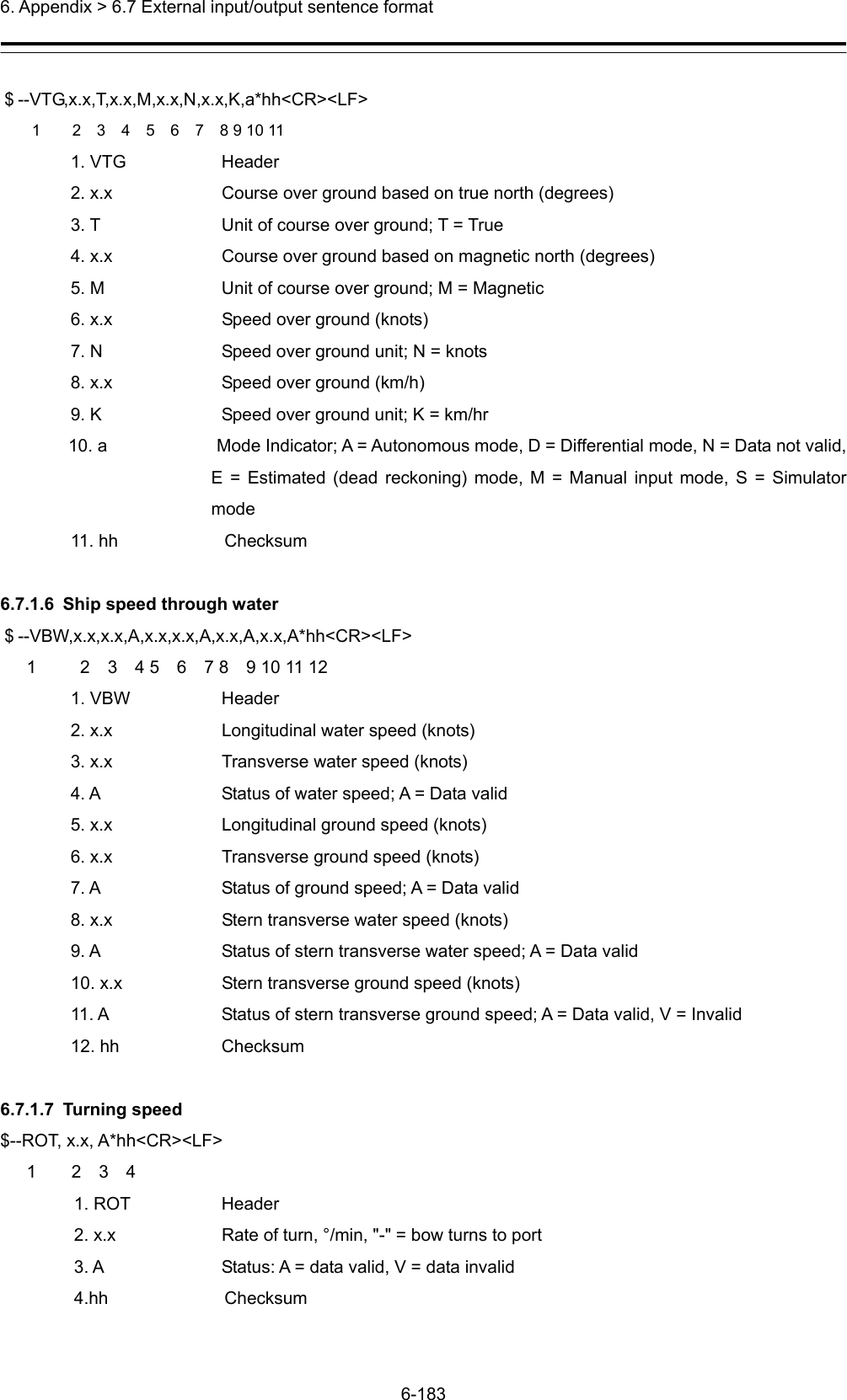
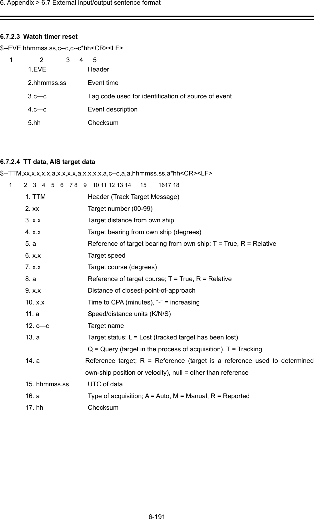
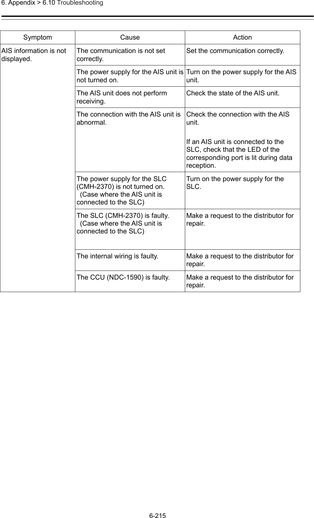
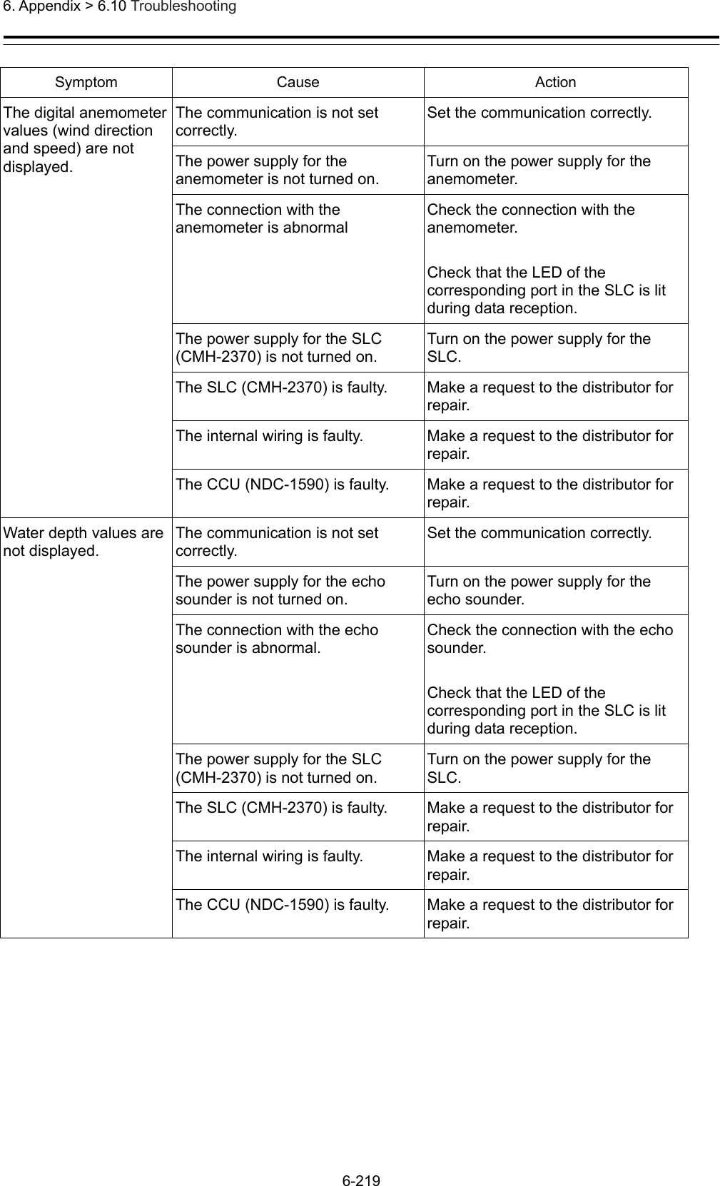
![6. Appendix > 6.10 Troubleshooting 6-221 Symptom Cause Action Contact signals are not output. The power supply for the SLC (CMH-2370) is not turned on. (Case where contact signal output is acquired from the SLC) Turn on the power supply for the SLC. The SLC (CMH-2370) is faulty. (Case where contact signal output is acquired from the SLC) Make a request to the distributor for repair. The internal wiring is faulty. Make a request to the distributor for repair. The CCU (NDC-1590) is faulty. Make a request to the distributor for repair. The scanner unit is not recognized The connection with the scanner unit is abnormal. Check the connection with the scanner unit. Power is not supplied from the PSU to the scanner unit. Check the power supply wiring between the PSU and the RIF. Check the power supply connection inside of the scanner unit. [Note] For checking wiring inside of the scanner unit, always request the work to the specialized service person. Before starting the work, turn off the power supply of the display unit. Otherwise, an unexpected accident may occur. Only AC power is supplied to the PSU. (NKE-2254 or NKE-2103 is connected as the scanner unit) To connect the NKE-2254 or NKE-2103 scanner unit, the DC power supply must be connected to the PSU. The RIF (CQD-2273) is not set correctly. Set the RIF correctly. The RIF (CQD-2273) is faulty. Make a request to the distributor for repair. The scanner unit is faulty. Make a request to the distributor for repair. The internal wiring is faulty. Make a request to the distributor for repair. The CCU (NDC-1590) is faulty. Make a request to the distributor for repair.](https://usermanual.wiki/Japan-Radio-Co/NKE2632.Installation-Manual-Part-11/User-Guide-2791044-Page-46.png)
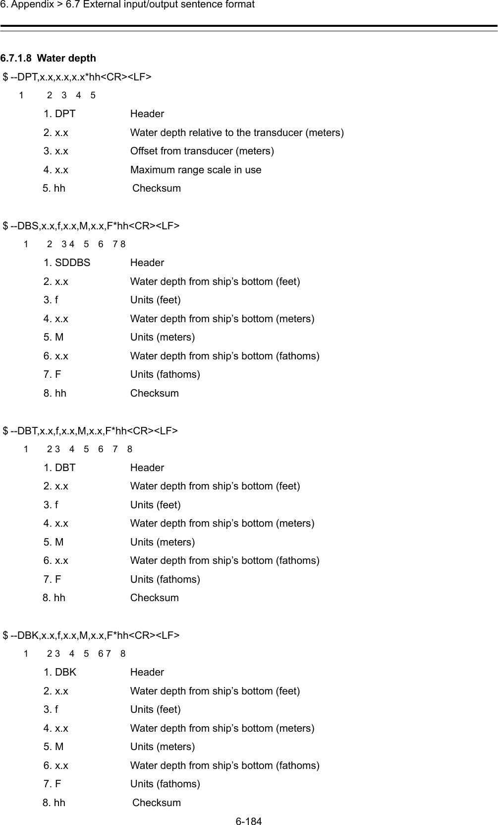
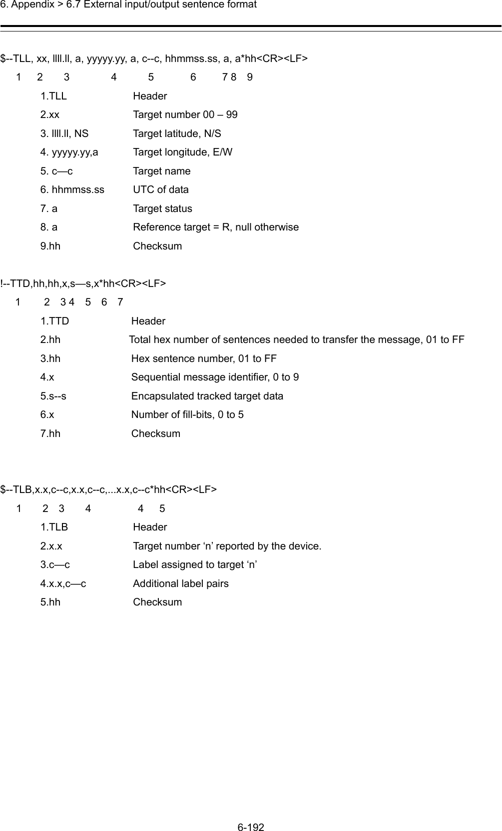
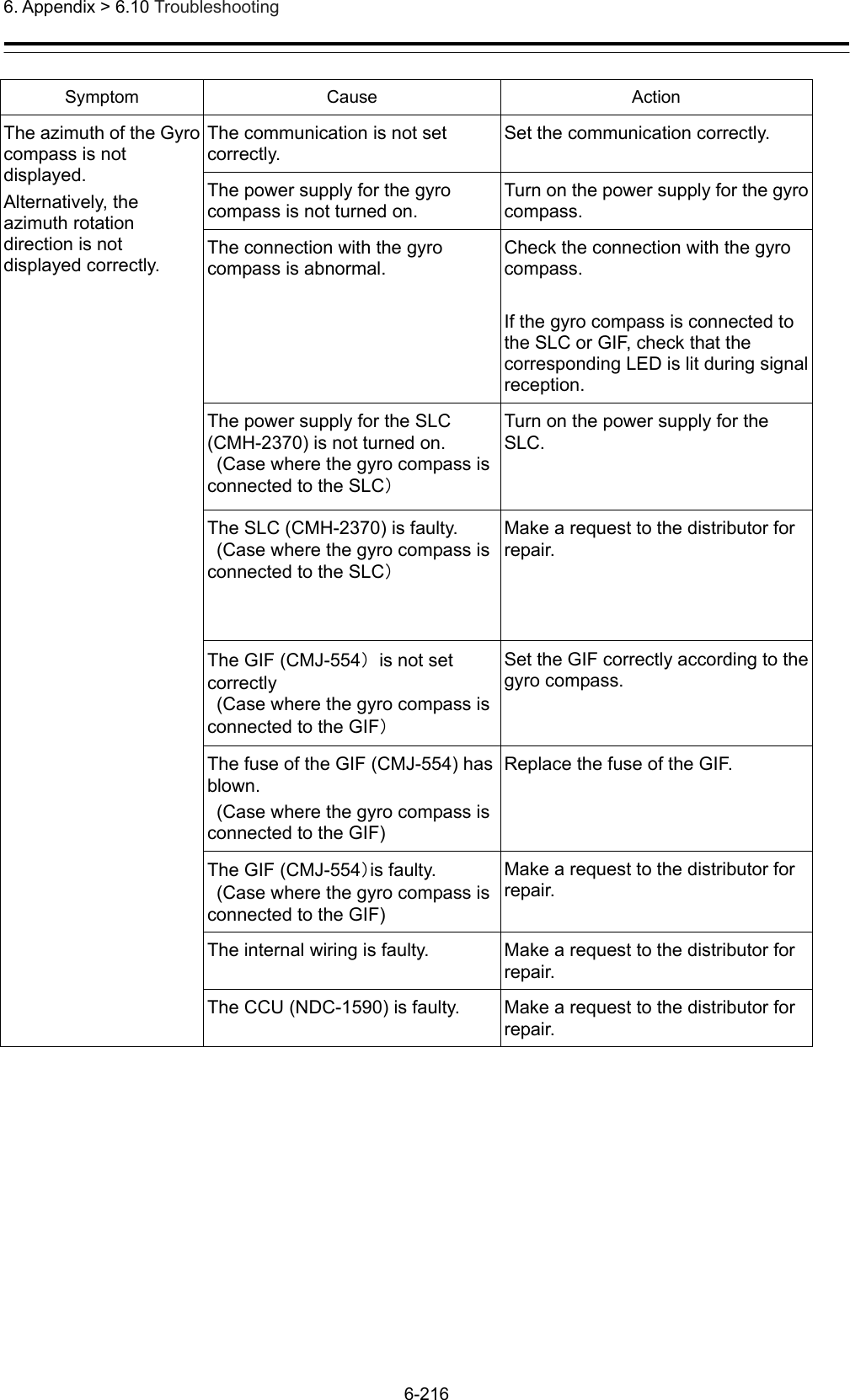
![6. Appendix > 6.10 Troubleshooting 6-222 Symptom Cause Action The power is not supplied to the scanner unit. The connection with the scanner unit is abnormal. Check the connection with the scanner unit. The connection with the scanner unit is abnormal and overcurrent protection is functioning in the PSU.Check the connection with the scanner unit and remove the cause of short-circuit. DC power is not supplied to the PSU. (NKE-2254 or NKE-2103 is connected as the scanner unit) To connect the NKE-2254 or NKE-2103 scanner unit, DC power supply must be connected to the PSU. The DC24V output fuse is blown out. (NKE-2254 or NKE-2103 is connected as the scanner unit.) After removing the cause of fuse blow-out, replace the fuse. The fuse is the 15A blade fuse at the front of the PSU (NBD-913). The RIF (CQD-2273) is faulty. Make a request to the distributor for repair. The internal wiring is faulty. Make a request to the distributor for repair. The PSU (NBD-913) is abnormal. Make a request to the distributor for repair. The CCU (NDC-1590) is faulty. Make a request to the distributor for repair. The preheat count down of the scanner unit is not displayed. The connection with the scanner unit is abnormal. Check the connection with the scanner unit. The safety switch of the scanner unit is set to OFF. Set the safety switch of the scanner unit to ON. [Note] For operating the safety switch of the scanner unit, always request the work to the specialized service person. Before starting the work, turn off the power supply of the display unit. Otherwise, an unexpected accident may occur. A solid-state scanner unit is connected. Preheat count-down is not displayed for a solid-state scanner unit. The scanner unit is faulty. Make a request to the distributor for repair. The RIF (CQD-2273) is not set correctly. Set the RIF correctly. The RIF (CQD-2273) is faulty. Make a request to the distributor for repair.](https://usermanual.wiki/Japan-Radio-Co/NKE2632.Installation-Manual-Part-11/User-Guide-2791044-Page-47.png)
![6. Appendix > 6.10 Troubleshooting 6-223 Symptom Cause Action The internal wiring is faulty. Make a request to the distributor for repair. The CCU (NDC-1590) is faulty. Make a request to the distributor for repair. The scanner unit does not rotate even if the [Transmit] button is pressed. The connection with the scanner unit is abnormal. Check the connection with the scanner unit. The safety switch of the scanner unit is set to OFF. Set the safety switch of the scanner unit to ON. [Note] For operating the safety switch of the scanner unit, always request the work to the specialized service person. Before starting the work, turn off the power supply of the display unit. Otherwise, an unexpected accident may occur. Power is not supplied from the PSU to the scanner unit. Check the power supply wiring between the PSU and the RIF. Check the power supply connection inside of the scanner unit. [Note] For checking the wiring inside of the scanner unit, always request the work to the specialized service person. Before starting the work, turn off the power supply of the display unit. Otherwise, an unexpected accident may occur. The motor driver circuit inside of the scanner unit is not set correctly. (NKE-1632, NKE-2632, or NKE-2632-H is connected as the scanner unit.) Set the motor driver circuit correctly. [Note] For setting the motor driver circuit, always request the work to the specialized service person. Before starting the work, turn off the power supply of the display unit. Otherwise, an unexpected accident may occur. The rotating part of the scanner unit is frozen. De-freeze the frozen section by using the neck heater option.](https://usermanual.wiki/Japan-Radio-Co/NKE2632.Installation-Manual-Part-11/User-Guide-2791044-Page-48.png)
![6. Appendix > 6.10 Troubleshooting 6-224 Symptom Cause Action Strong wind of relative wind velocity exceeding 100 kt (about 51.5 m/s) is blowing. When strong wind of relative wind velocity exceeding 100 kt is blowing, the scanner unit does not rotate due to the protection function. The scanner unit is faulty. Make a request to the distributor for repair. The RIF (CQD-2273) is faulty. Make a request to the distributor for repair. The internal wiring is faulty. Make a request to the distributor for repair. The PSU (NBD-913) is abnormal. Make a request to the distributor for repair. The CCU (NDC-1590) is faulty. Make a request to the distributor for repair. No radar image is displayed. The connection with the scanner unit is abnormal. Check the connection with the scanner unit. The GAIN value is set to the minimum. Set a proper value for GAIN. The SEA/RAIN value is set to the maximum. Set a proper value for SEA/RAIN. The magnetron is deteriorated significantly. (Case where an scanner unit that uses a magnetron is connected) Replace the magnetron. [Note] For magnetron replacement, always request the work to the specialized service person. Before starting the work, turn off the power supply of the display unit. Otherwise, an unexpected accident may occur. The scanner unit is faulty. Make a request to the distributor for repair. The RIF (CQD-2273) is faulty. Make a request to the distributor for repair. The internal wiring is faulty. Make a request to the distributor for repair. The PSU (NBD-913) is abnormal. Make a request to the distributor for repair. The CCU (NDC-1590) is faulty. Make a request to the distributor for repair.](https://usermanual.wiki/Japan-Radio-Co/NKE2632.Installation-Manual-Part-11/User-Guide-2791044-Page-49.png)
![6. Appendix > 6.10 Troubleshooting 6-225 Symptom Cause Action Radar images cannot be tuned The magnetron is deteriorated significantly. (Case where a scanner unit that uses a magnetron is connected) Replace the magnetron. [Note] For magnetron replacement, always request the work to the specialized service person. Before starting the work, turn off the power supply of the display unit. Otherwise, an unexpected accident may occur. A solid-state scanner unit is connected. Tuning bar is not displayed for a solid-state scanner unit. The azimuth of the radar image is not displayed correctly. The azimuth is not set correctly. Set the azimuth correctly. CCRP is not set correctly. Set CCRP correctly. The GPS antenna position is not set correctly. Set the GPS antenna position correctly. The range of the radar image is not displayed correctly. The range is not set correctly. Set the range correctly. CCRP is not set correctly. Set CCRP correctly. The GPS antenna position is not set correctly. Set the GPS antenna position correctly. Interswitch Unit does not function. Power for the Interswitch Unit is not turned on. Turn on the power for the Interswitch Unit. The connection with the Interswitch Unit is abnormal. Check the connection with the Interswitch Unit. The Interswitch Unit is faulty. Make a request to the distributor for repair. The RIF (CQD-2273) is not set correctly. Set the RIF correctly. The RIF (CQD-2273) is faulty. Make a request to the distributor for repair. The internal wiring is faulty. Make a request to the distributor for repair. The CCU (NDC-1590) is faulty. Make a request to the distributor for repair. If the power supply is turned off, the trail data is cleared without being stored. The CCU (NDC-1590) is faulty. Make a request to the distributor for repair.](https://usermanual.wiki/Japan-Radio-Co/NKE2632.Installation-Manual-Part-11/User-Guide-2791044-Page-50.png)
![6. Appendix > 6.10 Troubleshooting 6-226 Symptom Cause Action Radar images cannot be overlaid. There is no optional license for radar overlay. Implement an optional license for radar overlay. The connection with the scanner unit is abnormal. Check the connection with the scanner unit. The connection with the radar display unit is abnormal. Check the connection with the radar display unit. The RIF (CQD-2273) is faulty. Make a request to the distributor for repair. The internal wiring is faulty. Make a request to the distributor for repair. The PSU (NBD-913) is faulty. Make a request to the distributor for repair. The CCU (NDC-1590) is faulty. Make a request to the distributor for repair. UPS does not function. The connection with UPS is faulty. Check the connection with UPS. UPS is not set correctly. Set UPS correctly. The UPS battery is extremely depleted. Replace the battery. [Note] At the battery replacement, make a request for the work to the specialized service staff. During the replacement, turn off the corresponding power supply breaker in the ship. Otherwise, an unexpected accident may occur. The internal wiring is faulty. Make a request to the distributor for repair. UPS is faulty. Make a request to the distributor for repair.](https://usermanual.wiki/Japan-Radio-Co/NKE2632.Installation-Manual-Part-11/User-Guide-2791044-Page-51.png)
![01ETM ISO 9001, ISO 14001 CertifiedPrinted in JapanMarine Service Department+81-3-3492-1305+81-3-3779-1420tmsc@jrc.co.jpTelephone :Facsimile :e-mail :Alphatron Marine Systems Pte LtdTelephone :Facsimile :e-mail :+65 6863 0335+65 6863 3305service@alphatronmarinesystems.comSingapore BranchSEATTLE BranchTelephone :Facsimile :e-mail :+1-206-654-5644+1-206-654-7030marineservice@jrcamerica.comCODE No.7ZPNA4466ACODE No.7ZPNA4466AJUL. 2015 Edition 3 JRCJUL. 2015 Edition 3 JRCNot use the asbestos For further information,contact:URL http://www.jrc.co.jpAlphatron Marine B.V.Telephone :Facsimile :e-mail :+31 (0)10- 453 4000+31 (0)10- 452 9214service@alphatronmarine.comRotterdam (Head office)URL http://www.alphatronmarine.comMARINE RADAR EQUIPMENTMARINE RADAR EQUIPMENT/ECDIS/CONNING/ECDIS/CONNINGINSTALLATION MANUALINSTALLATION MANUALJMR-9230-S/S3JMR-9230-S/S3JMR-9225-7X3/9X3/6X/9X/6XHJMR-9225-7X3/9X3/6X/9X/6XHJMR-9210-6X/6XHJMR-9210-6X/6XHJMR-9272-SJMR-9272-SJMR-9282-S/SHJMR-9282-S/SHJMR-7230-S/S3JMR-7230-S/S3JMR-7225-7X3/9X3/6X/9X/6XHJMR-7225-7X3/9X3/6X/9X/6XHJMR-7210-6X/6XHJMR-7210-6X/6XHJMR-7272-SJMR-7272-SJMR-7282-S/SHJMR-7282-S/SHJAN-9201JAN-9201JAN-7201JAN-7201JAN-9202JAN-9202JAN-7202JAN-7202](https://usermanual.wiki/Japan-Radio-Co/NKE2632.Installation-Manual-Part-11/User-Guide-2791044-Page-53.png)