Japan Radio Co NKE2632 Solid State S-Band Marine Radar User Manual Installation Manual Part 5
Japan Radio Co Ltd. Solid State S-Band Marine Radar Installation Manual Part 5
Contents
- 1. Installation Manual Part 1
- 2. Installation Manual Part 2
- 3. Installation Manual Part 3
- 4. Installation Manual Part 4
- 5. Installation Manual Part 5
- 6. Installation Manual Part 6
- 7. Installation Manual Part 7
- 8. Installation Manual Part 8
- 9. Installation Manual Part 9
- 10. Installation Manual Part 10
- 11. Installation Manual Part 11
- 12. Instruction Manual Operation Part 1
- 13. Instruction Manual Operation Part 2
- 14. Instruction Manual Operation Part 3
- 15. Instruction Manual Operation Part 4
- 16. Instruction Manual Funtion Part 1
- 17. Instruction Manual Funtion Part 2
- 18. Instruction Manual Funtion Part 3
- 19. Instruction Manual Funtion Part 4
- 20. Instruction Manual Funtion Part 5
- 21. Instruction Manual Funtion Part 6
Installation Manual Part 5
3 Installation of Display Unit > 3.5 Installation of Option Equipment
3-94
9) While maintaining the OFF state of the circuit breaker for the power supply of the display unit, turn
ON the circuit breaker of the main power line and check that the LEDs of the UPS controller turn
ON/OFF as follows.
LED Color ON/OFF Status
Alarm Red OFF
Bat.-Mode
Bat.-Charge
Yellow Flashing or
OFF
Power In OK Green ON
10) Install the rear panel installed UPS to the frame. And wire the cable to pass through the cable tie base
No.16.
11) Install the 2 frames for installing the JB.
The installation of UPS ends above.
3 Installation of Display Unit > 3.5 Installation of Option Equipment
3-95
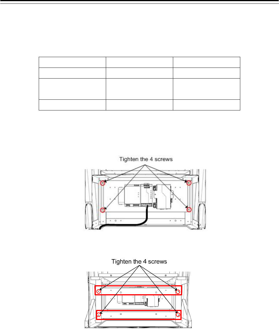
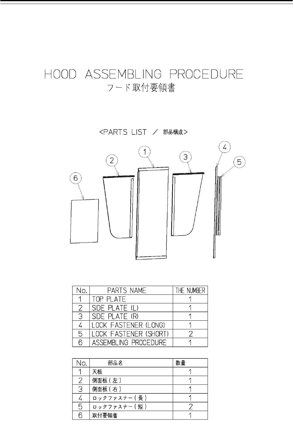
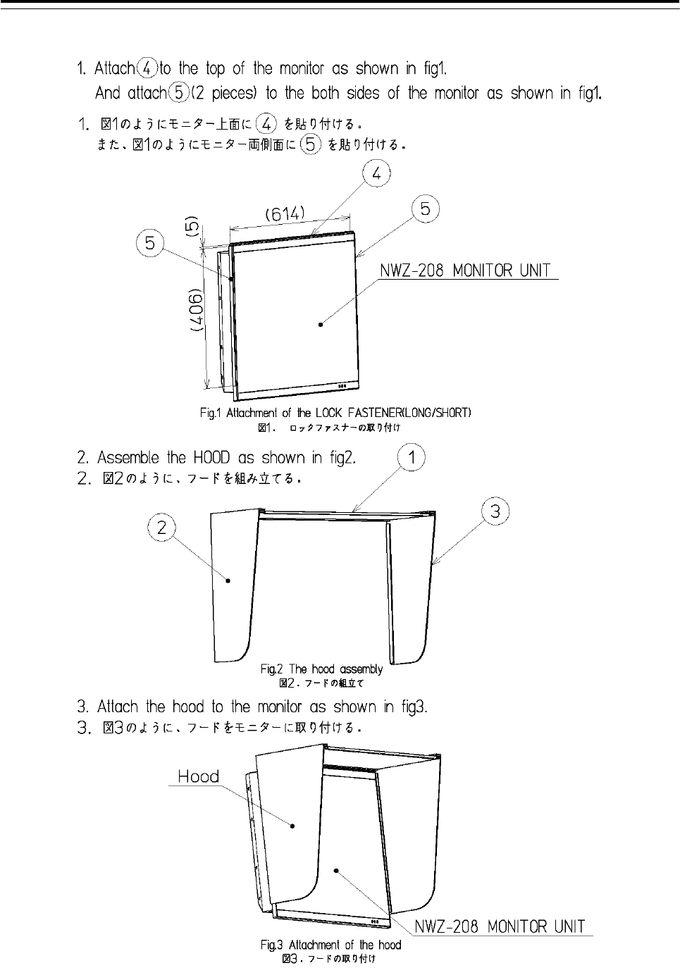
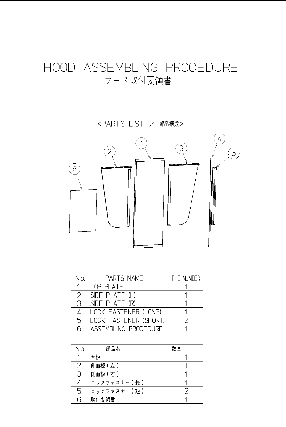
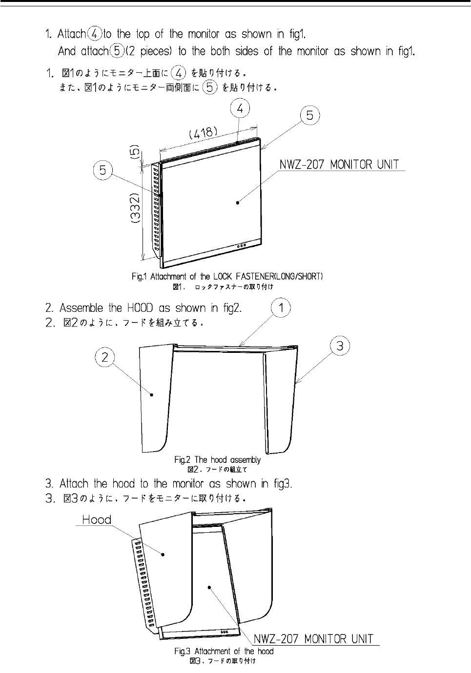
3.5.5 Installation of Hood
3.5.5.1 Installation of CWB-1620
3 Installation of Display Unit > 3.5 Installation of Option Equipment
3-96
3 Installation of Display Unit > 3.5 Installation of Option Equipment
3-97
3.5.6 Installation of CWB-1618
3 Installation of Display Unit > 3.5 Installation of Option Equipment
3-98
3 Installation of Display Unit > 3.6 Connections with Scanner and Transceiver
3-99
3.6 Connections with Scanner and Transceiver
Before conducting replacement work, turn OFF the circuit breaker for the power supply of the
display unit.
Before replacement work, be sure that all the LEDs on the front of the PSU NBD-913
are unlit. Charged electricity may still remain in the internal capacitor.
Do not lose the bolt and screws as they will be needed again.
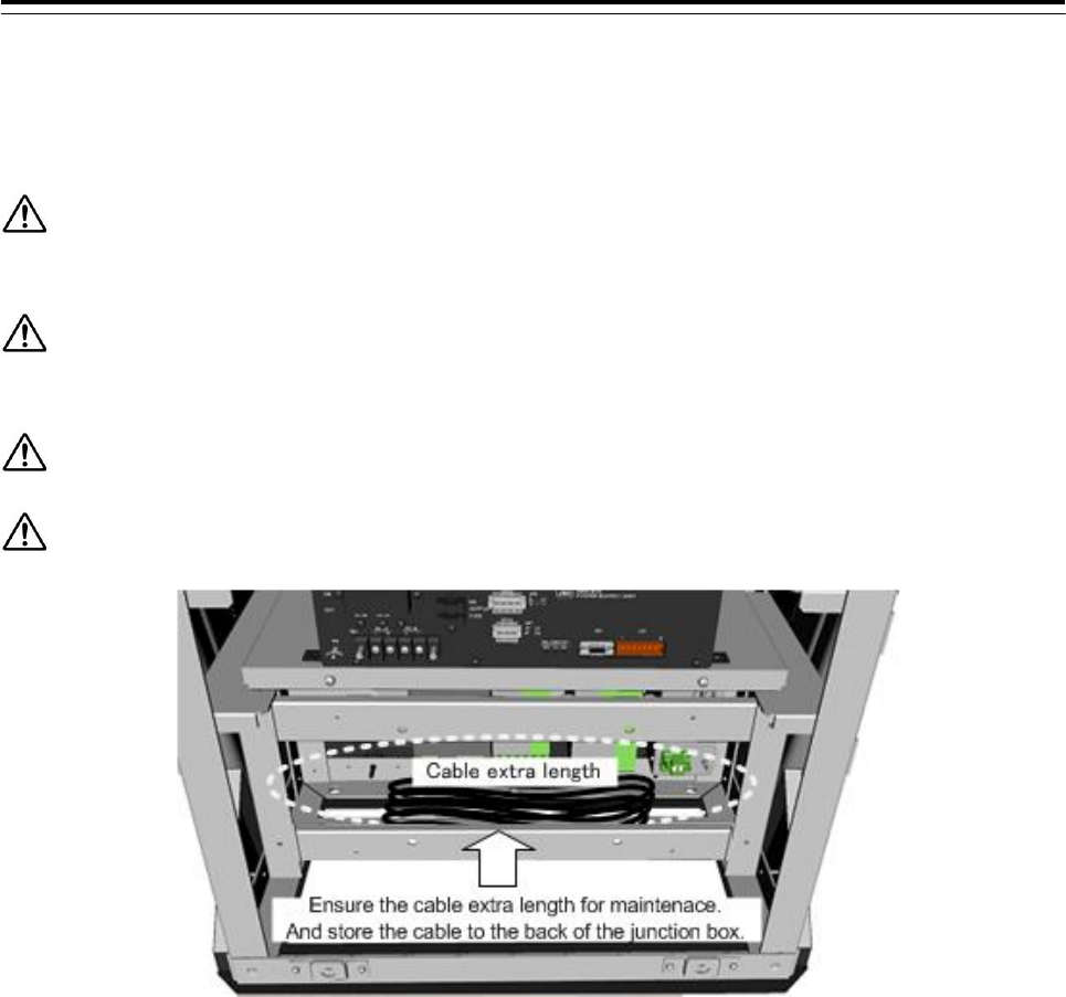
Ensure the cable extra length for maintenace. And store the cable to the back of the junction box.
3 Installation of Display Unit > 3.6 Connections with Scanner and Transceiver
3-100
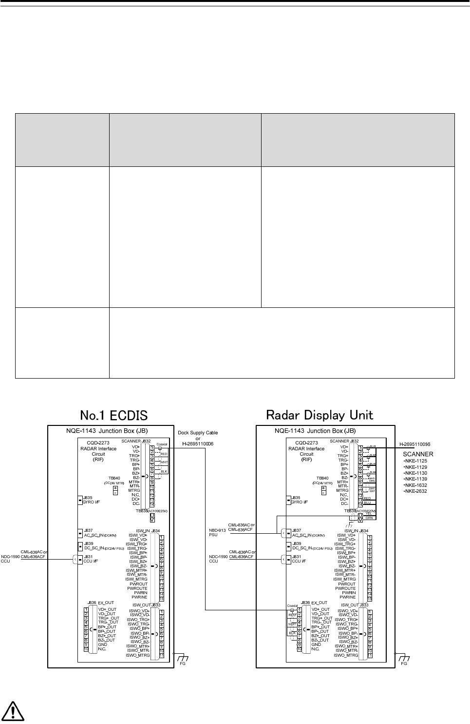
3.6.1 NKE-1125, NKE-1129, NKE-1130, NKE-1139, NKE-1632, NKE-2632 SCANNERS
Connect the device to J832 and TB838 of RADAR INTERFACE CIRCUIT CQD-2273
located in display unit (processing unit).
For the procedure for processing the equipment cable terminal, see 2.1.4 Cable end
processing method.
CML-836AC or
CML-836ACF
CML-836AC or
CML-836ACF
YEL
GRN
J835
SCANNER J832
TB840
(DC24V MTR)
CQD-2273
RADAR Interface
Circuit
(RIF)
NQE-1143
Junction Box (JB)
GYRO I/F
FG
1
2
3
4
5
6
7
8
+
-
TB838(AC100/220V)
U
V
1
2
3
4
5
6
7
8
1
2
3
4
5
6
7
8
1
2
3
4
5
6
7
8
ISW_IN
ISW_OUT
EX_OUT
J837
J839
J834
J833
J836
J831
CCU I/F
DC_SC_IN (DC24V PSU)
AC_SC_IN (DC48V)
PWROUT
PWROUTE
PWRIN
PWRINE
ISWI_VD+
ISWI_VD-
ISWI_TRG+
ISWI_TRG-
ISWI_BP+
ISWI_BP-
ISWI_BZ+
ISWI_BZ-
ISWI_MTR+
ISWI_MTR-
ISWI_MTRG
ISWO_VD+
ISWO_VD-
ISWO_TRG+
ISWO_TRG-
ISWO_BP+
ISWO_BP-
ISWO_BZ+
ISWO_BZ-
ISWO_MTR+
ISWO_MTR-
ISWO_MTRG
VD+_OUT
VD-_OUT
TRG+_OUT
TRG-_OUT
BP+_OUT
BP-_OUT
BZ+_OUT
BZ-_OUT
GND
N.C.
VD+
VD-
TRG+
TRG-
BP+
BP-
BZ+
BZ-
MTR+
MTR-
N.C.
DC+
DC-
MTRG
BLK1
WHT-
ORN
BLK2
BLK3
BLK4
WHT-
WHT
RED
BLU
H-2695110056 SCANNER
・NKE-1125
・NKE-1129
・NKE-1130
・NKE-1139
・NKE-1632
・NKE-2632
NBD-913
PSU
NDC-1590
CCU
Confirm the Model of Scanner Unit and input power supply of Display Unit.
Radar Model Scanner Unit Model of 100-115VAC Scanner Unit Model of 220-240VAC
JMR-9230-S3 NKE-1139-1 NKE-1139-2
JMR-9230-S NKE-1130-1 NKE-1130-2
JMR-9225-7X3 NKE-1129-71 NKE-1129-72
JMR-9225-9X3 NKE-1129-91 NKE-1129-92
JMR-9225-6X NKE-1125-61 NKE-1125-62
JMR-9225-9X NKE-1125-91 NKE-1125-92
3 Installation of Display Unit > 3.6 Connections with Scanner and Transceiver
3-101
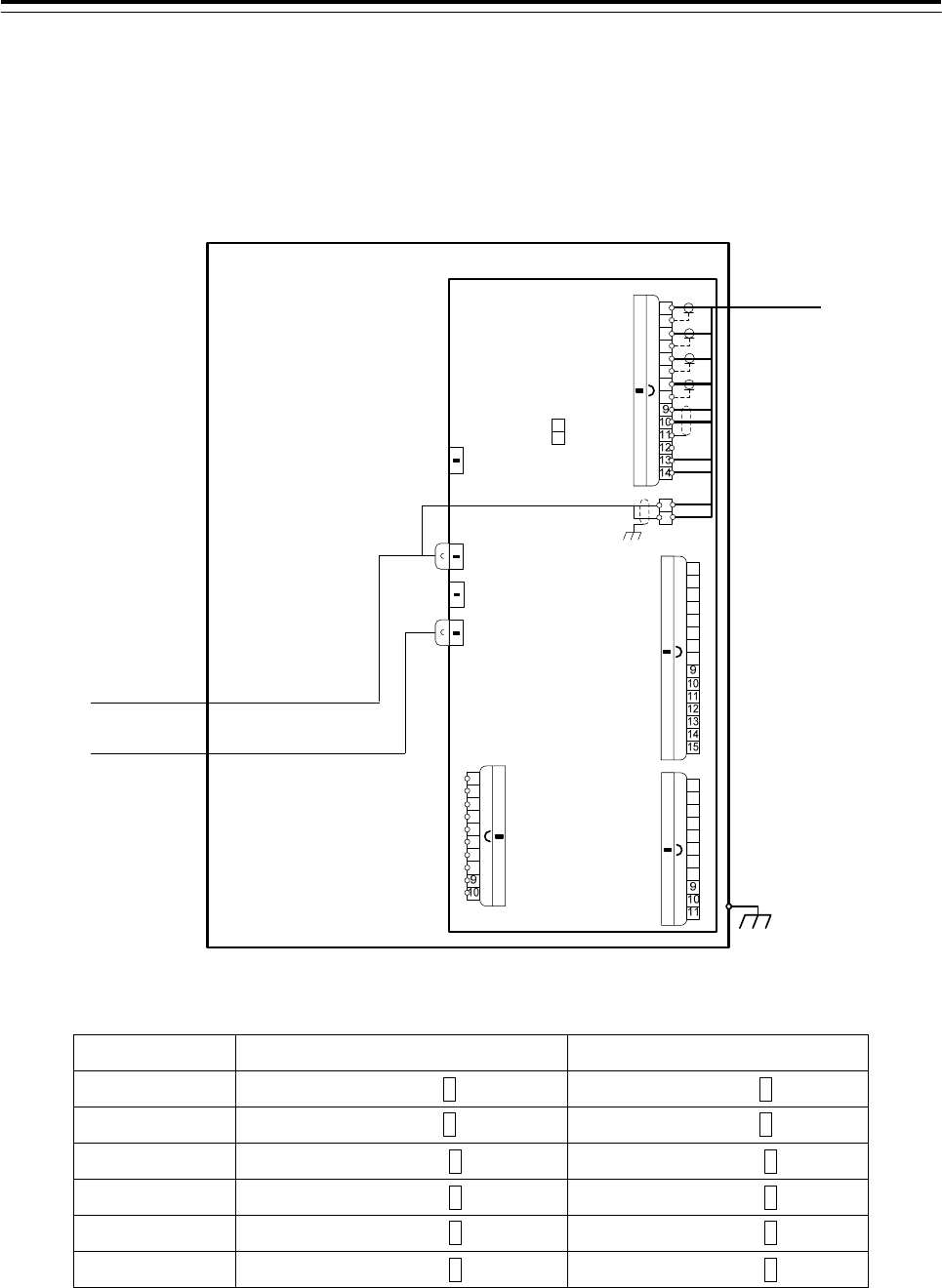
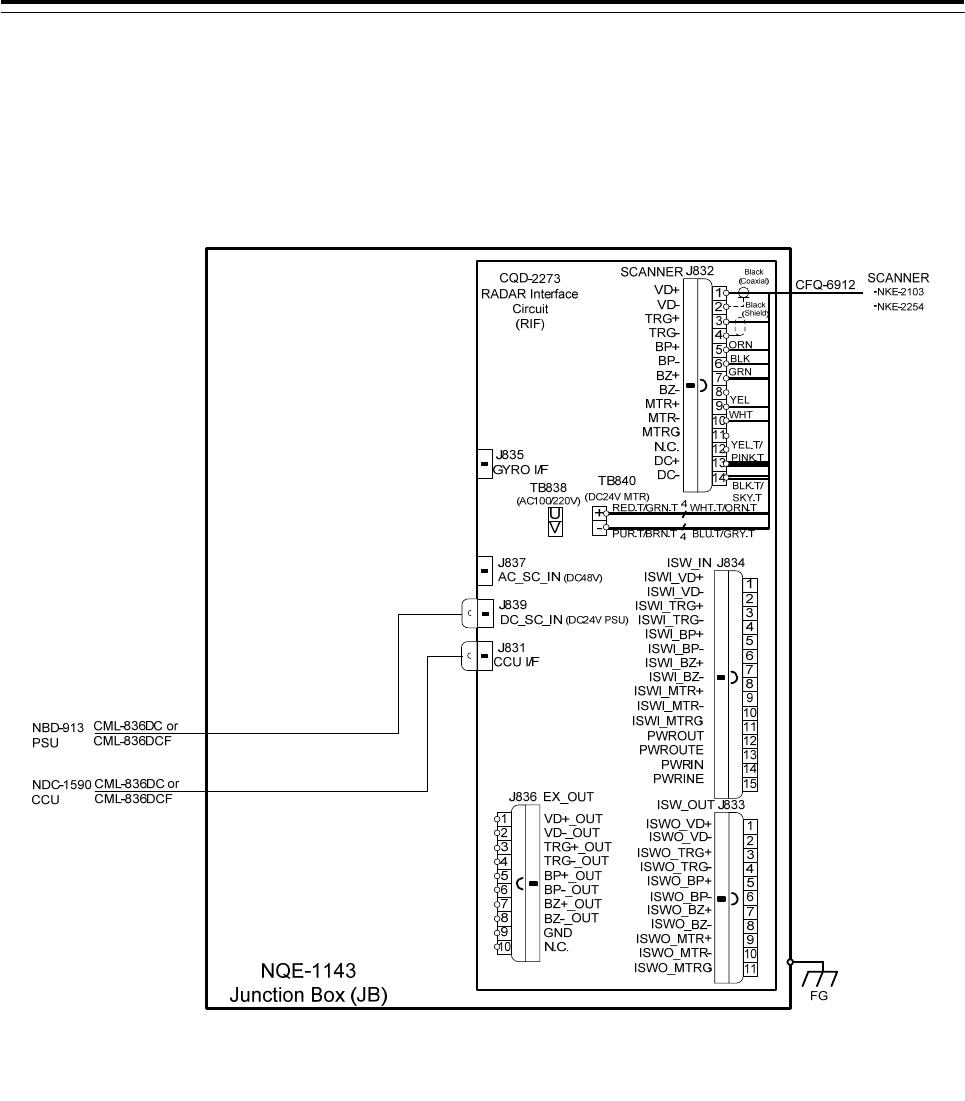
3.6.2 NKE-2103, NKE-2254 SCANNERS
Connect the device to J832 and TB840 of RADAR INTERFACE CIRCUIT CQD-2273
located in display unit (processing unit).
For the procedure for processing the equipment cable terminal, see 2.1.1 CFQ-6912-**.
3 Installation of Display Unit > 3.6 Connections with Scanner and Transceiver
3-102
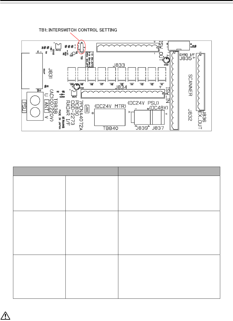
3.6.3 Settings for RADAR I/F Circuit
Fig 3-26 CQD-2273 Radar Interface Circuit TB1
Table 3-2 Radar Interface Circuit TB1 Settings
Radar Interface Circuit TB1 Settings Description
1-2 SHORT CIRCUIT
ISW_AUTO
(Factory default)
You can switch the scanner unit to be
used on your Display unit via the
Interswitch unit.
2-3 SHORT CIRCUIT
ISW_ONLY
(Not allowed)
Scanner signals always come down to
your Display unit via the Interswitch unit.
You can switch them on your Display unit
in service mode.
OPEN
ISW_OFF
(Not allowed)
Scanner signals come down to your
Display unit directly. Since they do not
come through the Interswitch unit, you
cannot switch them.
If it is not suggested from JRC office, do not set “2-3 SHORT CIRCUIT” or “OPEN” the TB1 of Radar
Interface Circuit. It may cause a lower radar system performance.
3 Installation of Display Unit > 3.6 Connections with Scanner and Transceiver
3-103
3.6.3.1 Connection procedure between Radar Interface Circuit and Scanner Unit
1. Connect as follows Radar Interface Circuit and Scanner Unit.
(J832: Signal TB838: AC Power TB840: DC Power)
AC Motor Scanner Unit:
NKE-1139、NKE-1130、NKE-1632、NKE-2632、NKE-2632-H、
NKE-1129-7、NKE-1129-9、NKE-1125-6、NKE-1125-9
J832 とTB838
DC Motor Scanner Unit:
NKE-2254-6HS、NKE-2103-6、NKE-2103-6HS
J832 と TB840
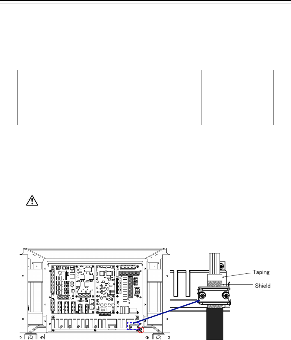
• For the procedures for processing the equipment cable end, see 2.1.4 Cable end processing
method.
• Fix the shield part of the equipment cable with pressing by metal fittings which is surrounded by a
dotted line frame in the figure below..Connect the shield to the thumbscrew surrounded by the
circle.(Recommended crimp terminals V5.5)
So that the braided shield is not shorted to the power supply terminal block, please insulate
the cable and fix with cable tie. Please put the Extra length of the cable to the bottom of the display
unit so that the not shorted to the UPS or SENSOR LAN switch unit.
• When connecting the interswitch unit, see 5.1 Installation of Interswitch Unit.
• When connecting the ECDIS, see 3.8 Connection with ECDIS.
3 Installation of Display Unit > 3.7 Connection with Sensors
3-104
3.7 Connection with Sensors
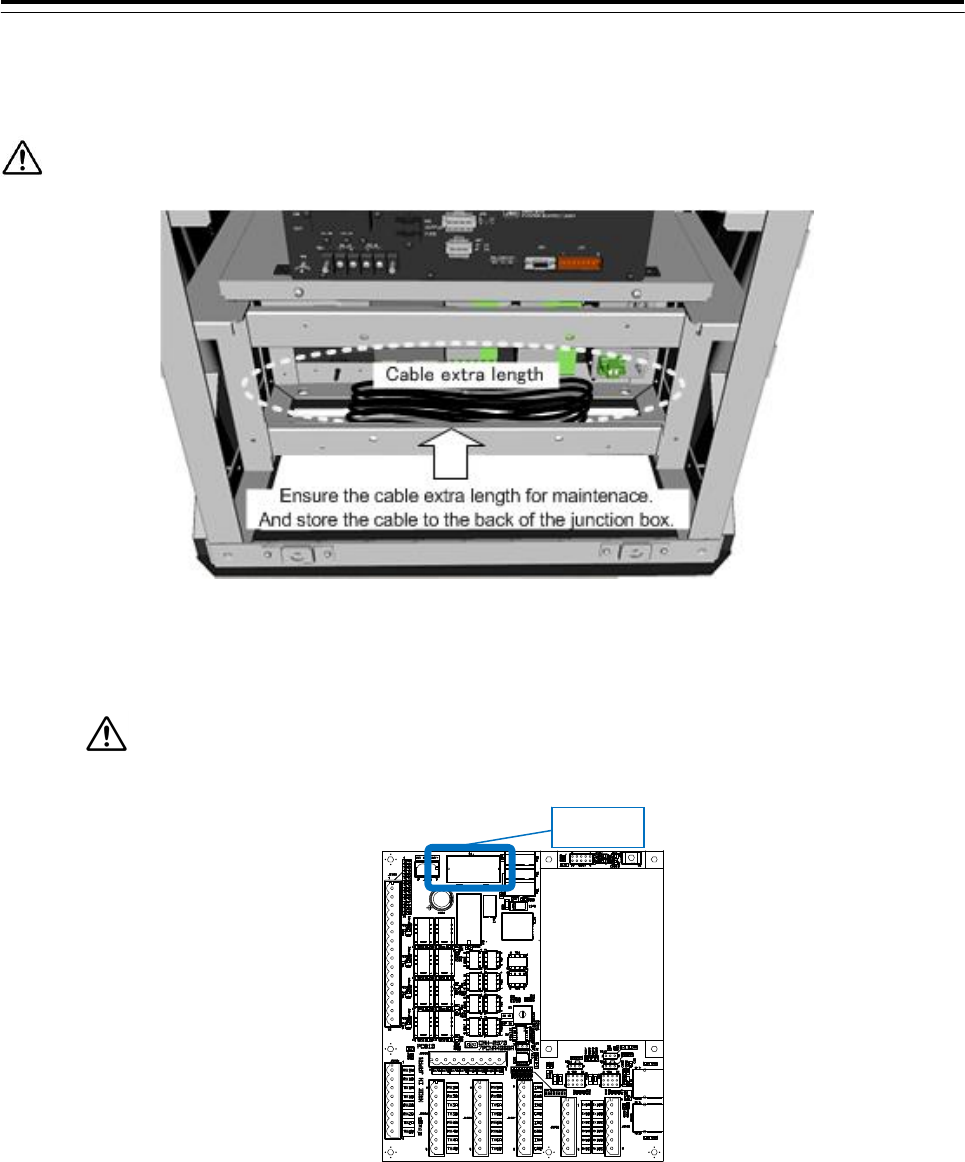
Ensure the cable extra length for maintenace. And store the cable to the back of the junction box.
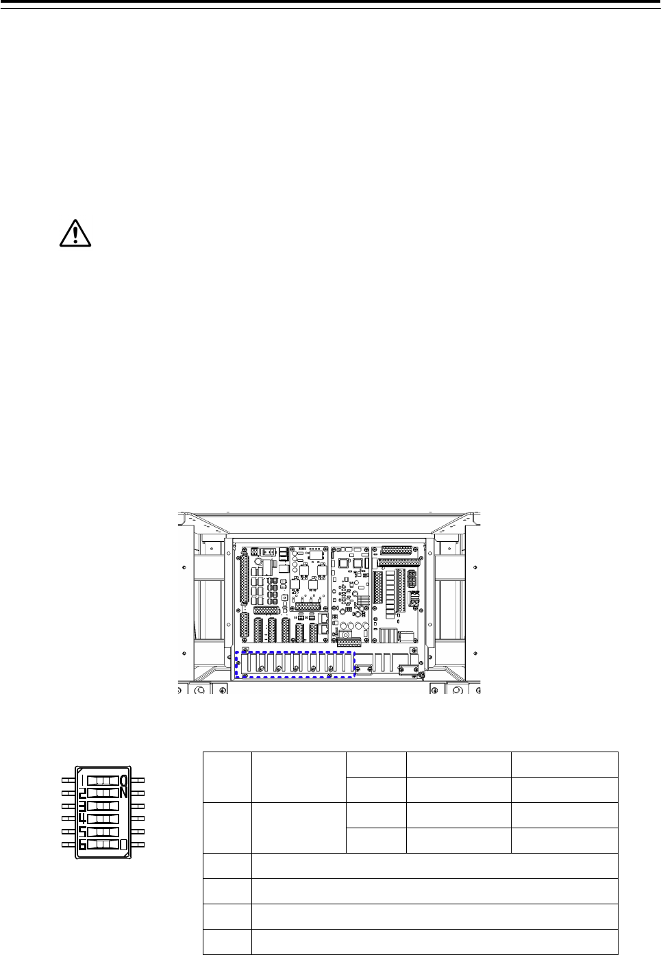
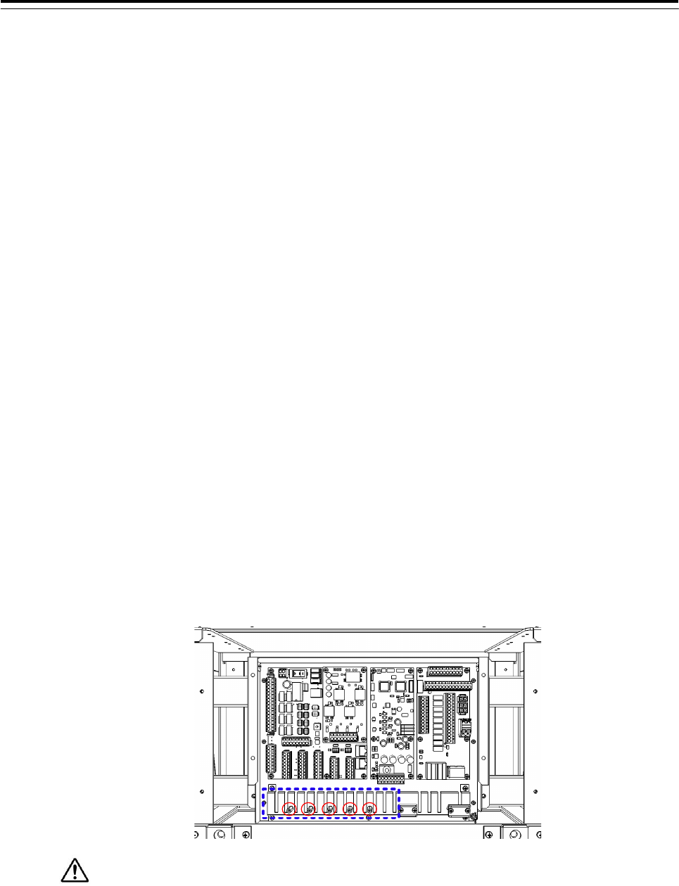
When the CMH-2370 has been installed to the Junction Box, start up the CMH-2370 by turning on
the switch S1. Refer to figure below for location of the S1.
If do not start up the CMH-2370, sensors what connected to the CMH-2370 does not take
effect.
S1 location on CMH-2370
S1
3 Installation of Display Unit > 3.7 Connection with Sensors
3-105
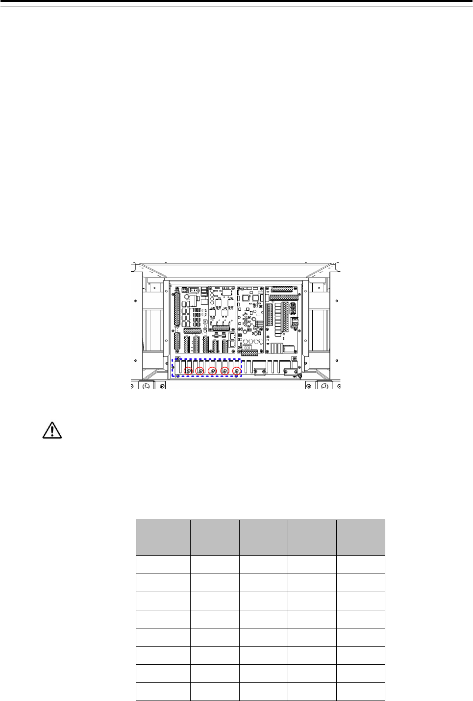
3.7.1 IEC61162-1 Connections
Connect the communication signals from sensors to the IEC61162-1 Port located on the
CMH-2370 in JUNCTION BOX NQE-1143. Communication signals from sensors will be connected
to terminals RX_A and RX_B which is IEC61162 standard. Communication signals to sensors will
be connected to terminals TX_A and TX_B which is IEC61162 standard. The number of port for
IEC61162-1 on CMH-2370 is 8 ports including each receiver and transmitter allocated at
J8103-J8106 on CMH-2370.
• See Fig 3-32:Connector location on CMH-2370 about location of J8103-J8106 on CMH-2370.
• To configure the port, refer to 4.6 Setting Up a Serial Port.
• Fix the signal cable with the clamp surrounded by the dotted line in the figure below.
• Connect the cable shield to the hex spacer surrounded by the circle in the figure below.
(Recommended crimp terminals V5.5)
So that the braided shield is not shorted to the power supply terminal block, please insulate the
cable and fix with cable tie. Please put the Extra length of the cable to the bottom of the display unit
so that the not shorted to the UPS or SENSOR LAN switch unit.
Table 3-3:Terminal Assign of J8103-J8106
Terminal
Number J8105 J8104 J8103 J8106
1 RX1A RX3A RX5A RX7A
2 RX1B RX3B RX5B RX7B
3 TX1A TX3A TX5A TX7A
4 TX1B TX3B TX5B TX7B
5 RX2A RX4A RX6A RX8A
6 RX2B RX4B RX6B RX8B
7 TX2A TX4A TX6A TX8A
8 TX2B TX4B TX6B TX8B
3 Installation of Display Unit > 3.7 Connection with Sensors
3-106
Fig 3-27 IEC61162-1 transmitter-receiver circuit
IEC61162-1 RX*A
IEC61162-1 TX*B
IEC61162-1 RX*B
IEC61162-1 TX*A
3 Installation of Display Unit > 3.7 Connection with Sensors
3-107
3.7.2 IEC61162-2 Connections
Connect the communication signals from sensors to the IEC61162-2 Port located on the
CMH-2370 in JUNCTION BOX NQE-1143. Communication signals from sensors will be
connected to terminals RX_A, RX_B and RX_C which is IEC61162 standard.
Communication signals to sensors will be connected to terminals TX_A, TX_B and TX_C
which is IEC61162 standard.
The number of port for IEC-61162-2 on CMH-2370 is two ports including each receiver
and transmitter allocated at J8101 and J8102 on CMH-2370.
• See Fig 3-32:Connector location on CMH-2370 about location of J8101-J8102 on CMH-2370.
• To configure the port, refer to 4.6 Setting Up a Serial Port.
• Fix the signal cable with the clamp surrounded by the dotted line in the figure below.
• Connect the cable shield to the hex spacer surrounded by the circle in the figure below.
(Recommended crimp terminals V5.5)
So that the braided shield is not shorted to the power supply terminal block, please insulate
the cable and fix with cable tie. Please put the Extra length of the cable to the bottom of the display
unit so that the not shorted to the UPS or SENSOR LAN switch unit.
Table 3-4:Terminal Assign of J8101 and J8102
Terminal
Number J8102 J8101
1 TX9A TX10A
2 TX9B TX10B
3 TX9C TX10C
4 RX9A RX10A
5 RX9B RX10B
6 RX9C RX10C
3 Installation of Display Unit > 3.7 Connection with Sensors
3-108
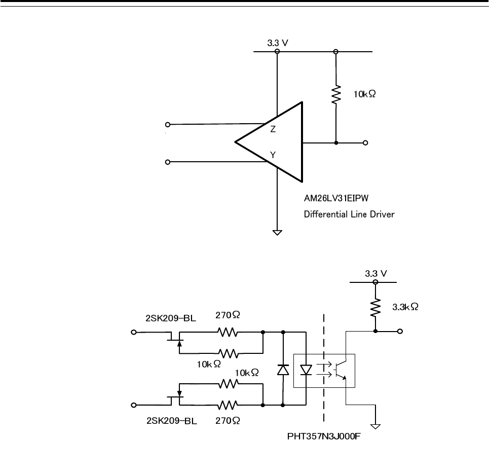
Fig 3-28 IEC61162-2 transmitter-receiver circuit
IEC61162-2 RX*B
IEC61162-2 RX*A
IEC61162-2 RX*C
IEC61162-2 TX*A
IEC61162-2 TX*B
IEC61162-2 TX*C
3 Installation of Display Unit > 3.7 Connection with Sensors
3-109
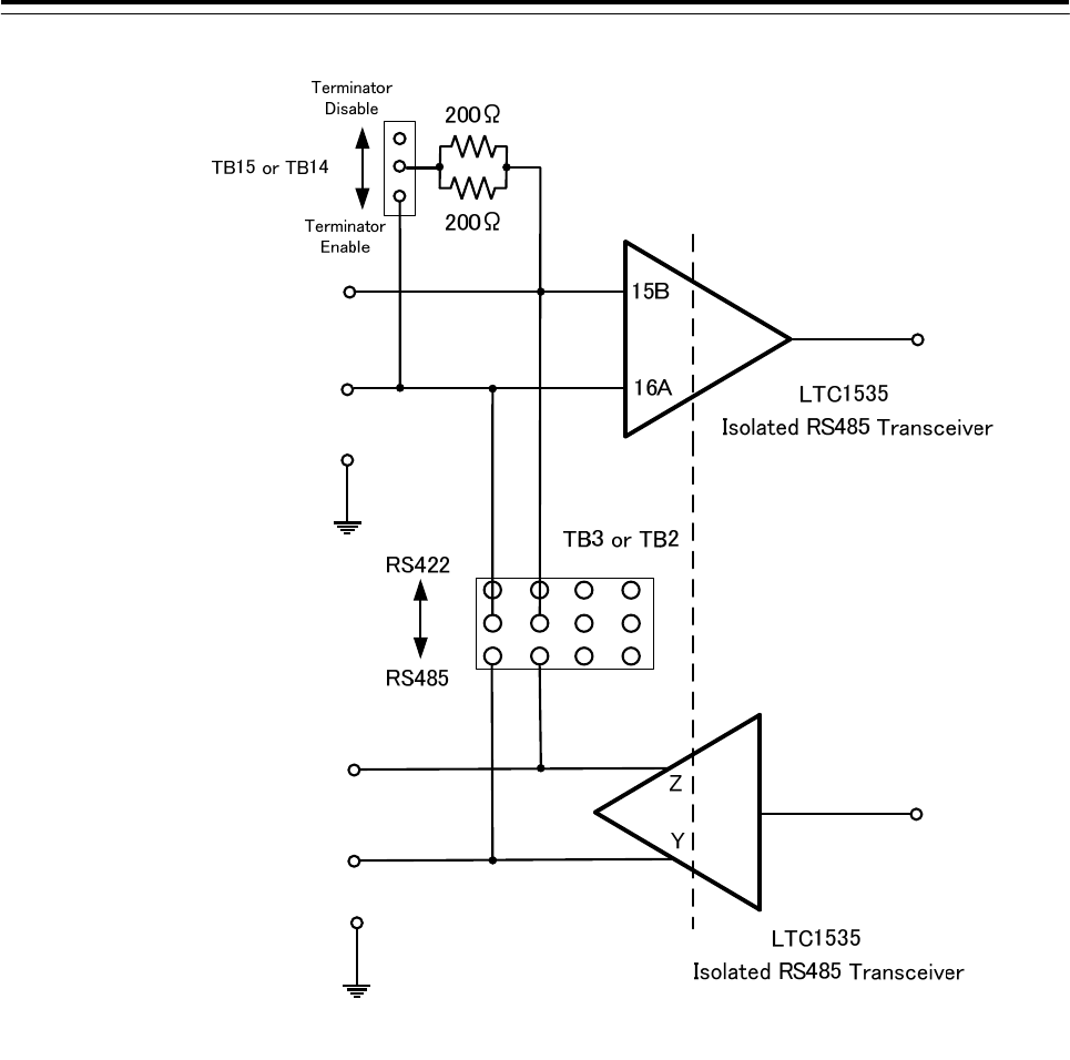
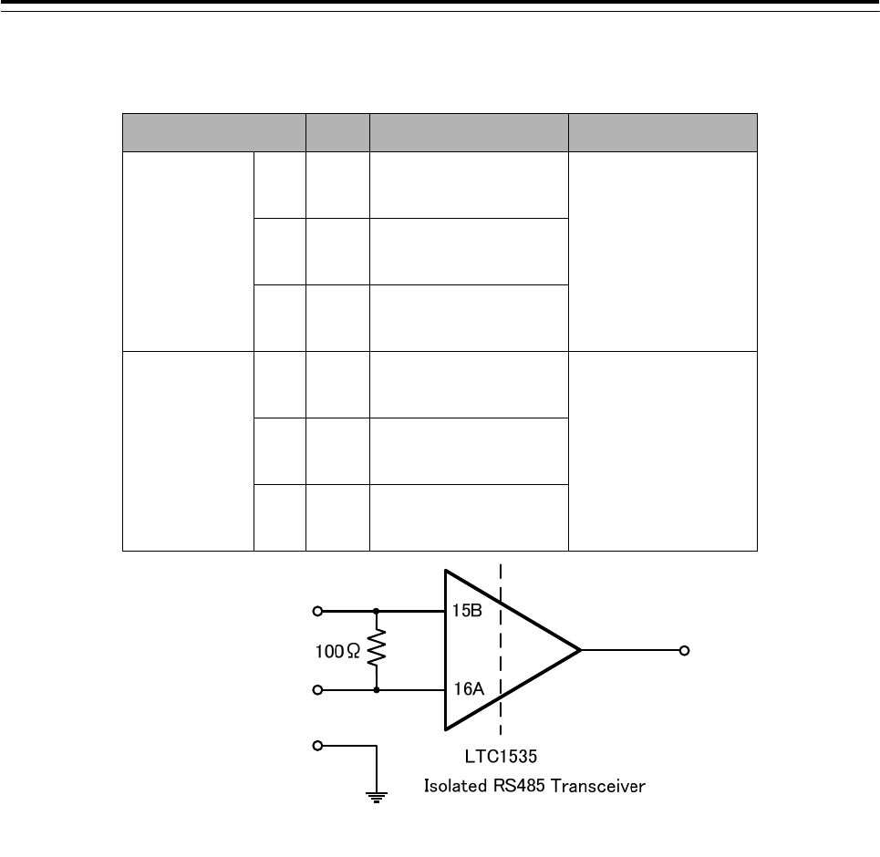
3.7.2.1 Communication Type and termination
Communication type of IEC61162-2 can be selected full duplex (IEC61162-2) mode or half
duplex (RS-485) mode by TB2 and TB3 setting on CMH-2370.
To select communication type for channel9, TB2 will be set by Short Plug.
To select communication type for channel10, TB3 will be set by Short Plug.
To set TB2 and TB3, refer to Table 3-5 and Fig 3-29 below.
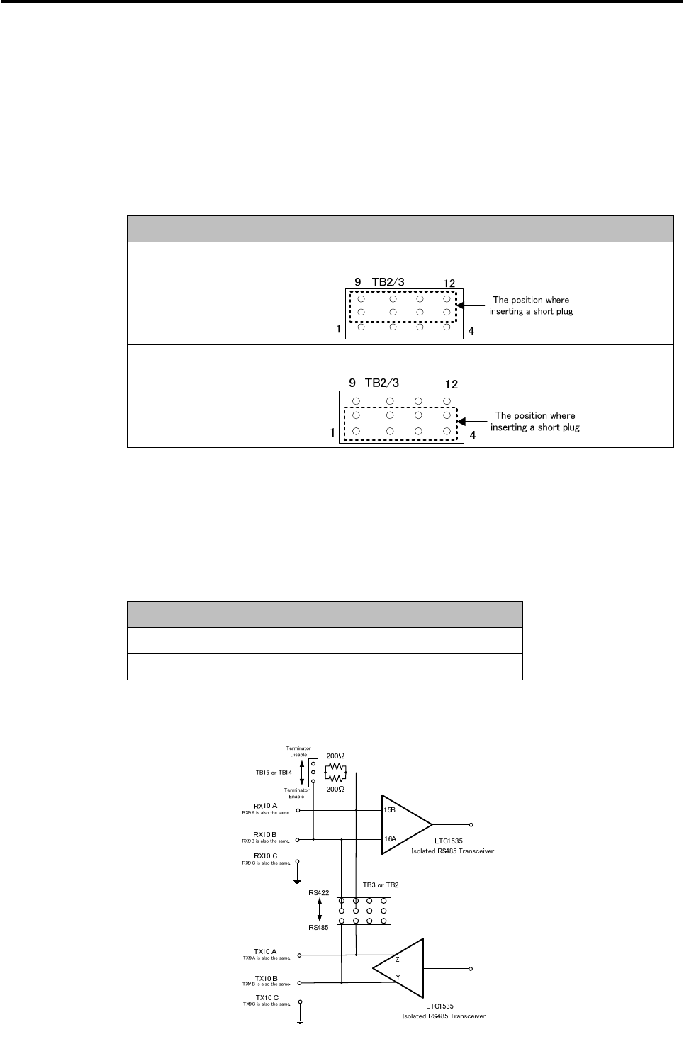
Table 3-5:Setting of communication type
Mode Setting of TB2 /TB3
Duplex
(RS-422)
Short circuit :5-9, 6-10, 7-11, 8-12
Half duplex
(RS-485)
Short circuit :5-1, 6-2, 7-3, 8-4
And the termination resister of receiver can be removable for multi connections by TB14
and TB15 setting on CMH-2370.
To set the termination for channel9, terminal of TB14 will be set by Short Plugs.
To set the termination for channel10, terminal of TB15 will be set by Short Plugs.
To set TB14 and TB15, refer to and Table 3-6 below.
Table 3-6:Setting of termination resister
Termination Terminal No. of TB14 and TB15
w Termination 2-3(Factory setting)
w/o Termination 1-2
Note : The location of TB2, TB3, TB14, TB15, Refer to Fig 3-32:Connector location on
CMH-2370.
Fig 3-29:Communication Type and termination Circuit Diagram
3 Installation of Display Unit > 3.7 Connection with Sensors
3-110
3.7.3 LAN Connection
CMH-2370 converts the sensor data which is IEC61162 into LAN protocol.
And, the data converted by CMH-2370 transfer to Display Unit via NQA-2443 Sensor LAN
Switch Unit. It can transfer the data not only receive from sensor to Display Unit but
transmit to sensor from Display Unit. CMH-2370 will be connected to NQA-2443 each
RJ-45 by an Ethernet cable.
If it is not suggested from JRC, do not connect PC or other maker's system to JRC-LAN.
•Connecting PC or other maker's system may cause a lower radar system performance.
•Connecting PC or other maker's system may cause a lower that performance.
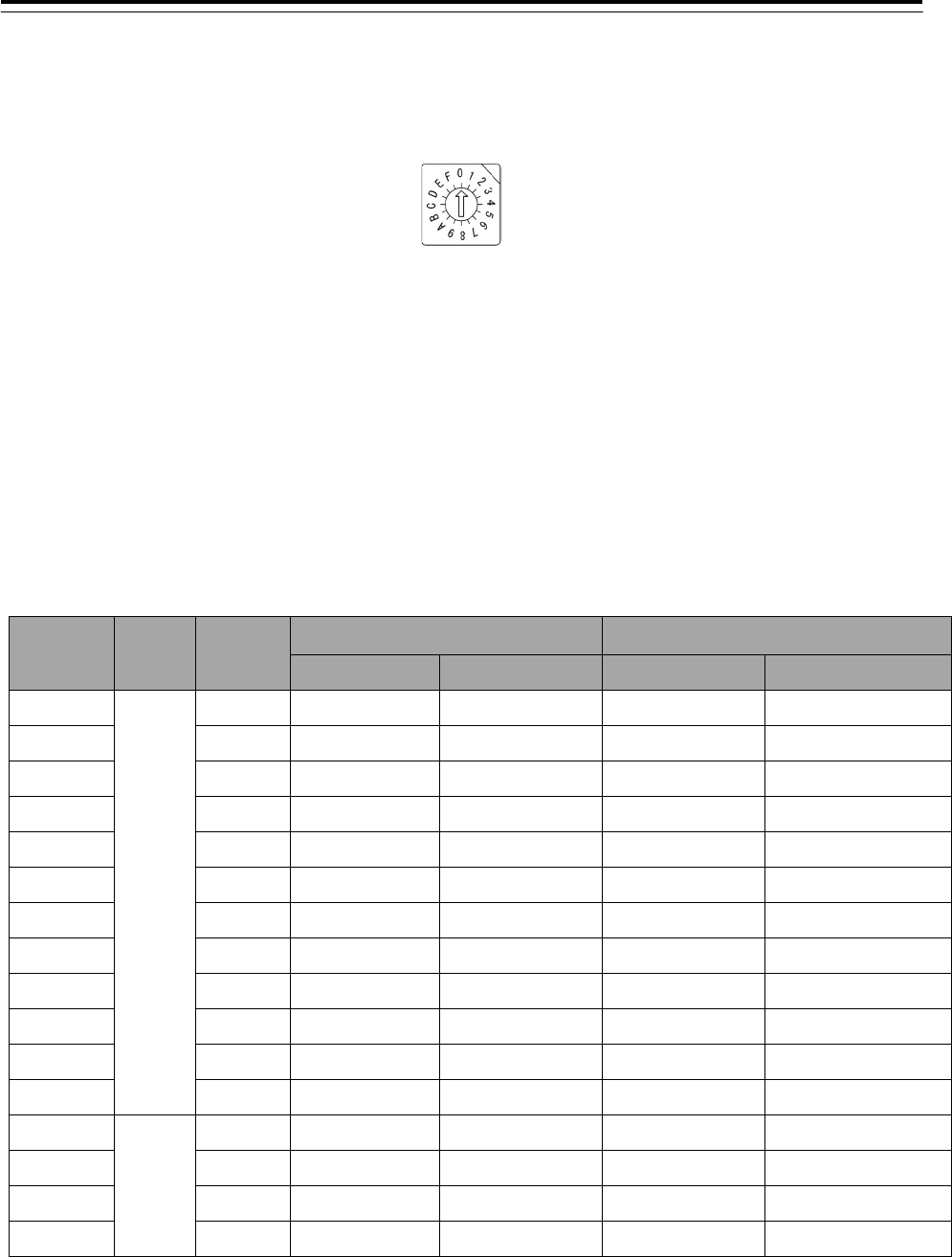
Either J8111 or J8112 selected by S4 will be used as an active LAN port.
And, you can select the data format either IEC61162-450 or JRC Formant by S4.
To set S4, refer to Table 3-7 below.
The location of J8111, J8112 and S4, refer to Fig 3-32:Connector location on CMH-2370
Fix the signal cable with the clamp surrounded by the dotted line in the figure below.
Table 3-7:S4 setting table
Fig 3-30:Outline of S4
To apply the setting, please restart CMH-2370 with the S1, because setting will be
reflected in the startup.
SW1 LAN Setting OFF Main Channel Use J8111
ON Sub Channel Use J8112
SW2 LAN Type
OFF Standard IEC61162-450
ON JRC JRC Format
SW3 Set Always OFF
SW4 Set Always OFF
SW4 Set Always OFF
SW6 Set Always OFF
3 Installation of Display Unit > 3.7 Connection with Sensors
3-111
If some number of CMH-2370s are installed and connected to the same NQA-2443
Sensor LAN Unit, you should change IP address of each CMH-2370 by S3 setting.
(Refer to Table 3-8:IP Address setting table)
Fig 3-31:Outline of S3
CMH-2370 to be connected to the IAS(Integrated Automation System) or AMS(Alert
Management System) is set the operation mode:ALC(Alert LAN Converter). Also in this
case, set the IP address in refer to Table 3-8:IP Address setting table.
The location of S3, refer to Fig 3-32:Connector location on CMH-2370.
Table 3-8:IP Address setting table
S3
Position Mode No. IEC61162-450 JRC Format
Main LAN Sub LAN Main LAN Sub LAN
0
SLC
SLC1 172.16.60.107 172.17.60.107 192.168.60.107 192.168.61.107
1 SLC2 172.16.60.108 172.17.60.108 192.168.60.108 192.168.61.108
2 SLC3 172.16.60.109 172.17.60.109 192.168.60.109 192.168.61.109
3 SLC4 172.16.60.110 172.17.60.110 192.168.60.110 192.168.61.110
4 SLC5 172.16.60.111 172.17.60.111 192.168.60.111 192.168.61.111
5 SLC6 172.16.60.112 172.17.60.112 192.168.60.112 192.168.61.112
6 SLC7 172.16.60.113 172.17.60.113 192.168.60.113 192.168.61.113
7 SLC8 172.16.60.114 172.17.60.114 192.168.60.114 192.168.61.114
8 SLC9 172.16.60.115 172.17.60.115 192.168.60.115 192.168.61.115
9 SLC10 172.16.60.116 172.17.60.116 192.168.60.116 192.168.61.116
A SLC11 172.16.60.117 172.17.60.117 192.168.60.117 192.168.61.117
B SLC12 172.16.60.118 172.17.60.118 192.168.60.118 192.168.61.118
C
ALC
ALC1 172.16.60.119 172.17.60.119 192.168.60.119 192.168.61.119
D ALC2 172.16.60.120 172.17.60.120 192.168.60.120 192.168.61.120
E ALC3 172.16.60.121 172.17.60.121 192.168.60.121 192.168.61.121
F ALC4 172.16.60.122 172.17.60.122 192.168.60.122 192.168.61.122

3 Installation of Display Unit > 3.7 Connection with Sensors
3-112
Fig 3-32:Connector location on CMH-2370
J8105
J8104 J8103
J8106
J8102 J8101
J8111
J8112
S3
S4
TB15
TB14
TB2 TB3
3 Installation of Display Unit > 3.7 Connection with Sensors
3-113
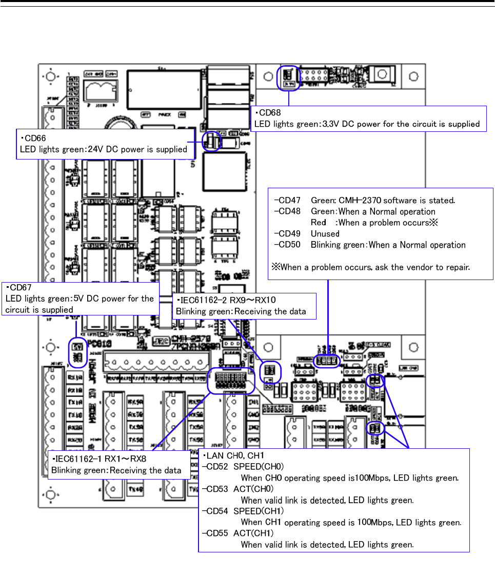
Fig 3-33 CMH-2370 LED
3 Installation of Display Unit > 3.7 Connection with Sensors
3-114
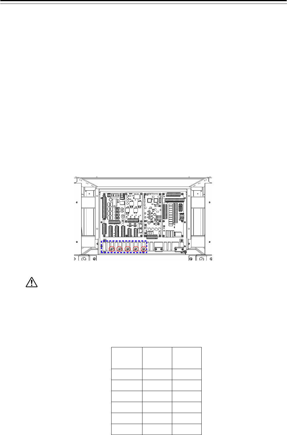
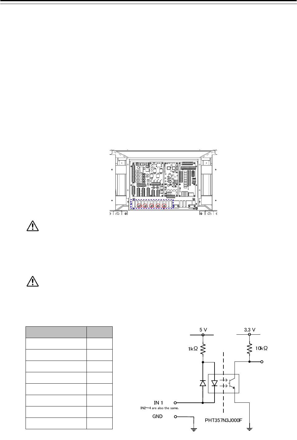
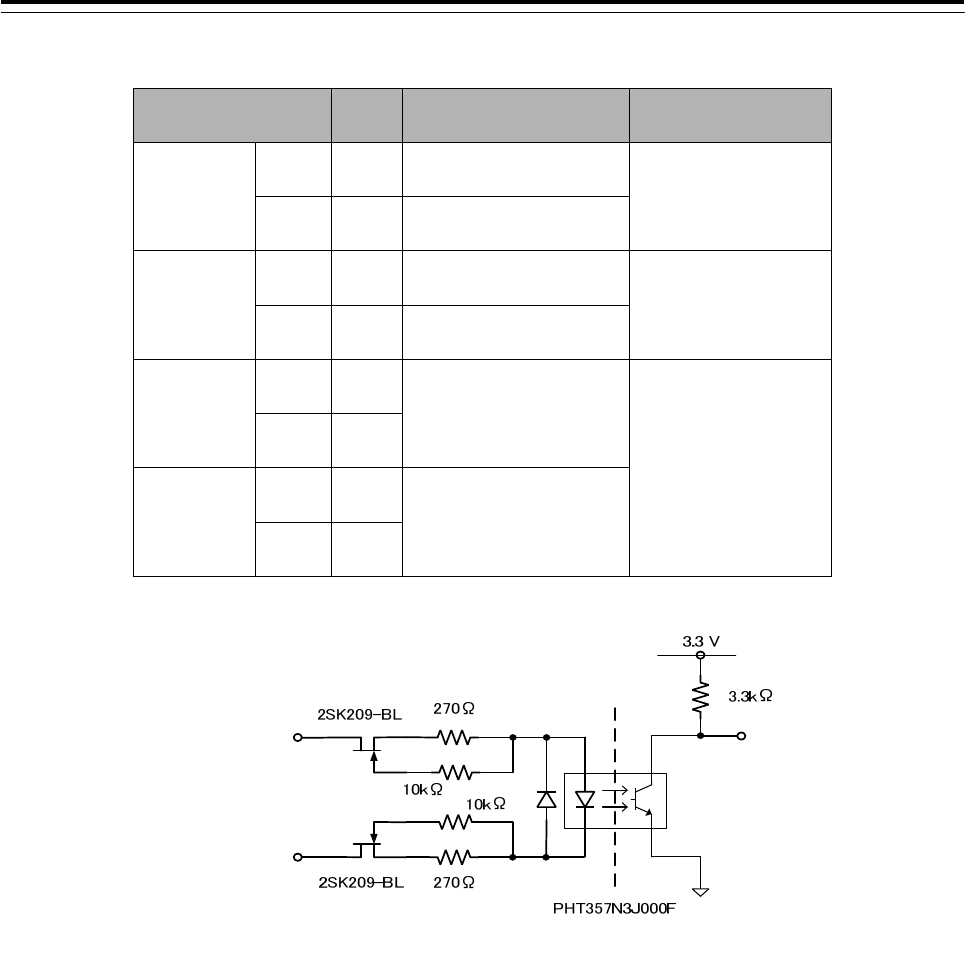
3.7.4 Contact Input
Connect the dry contact of other equipment to the Input port which is on CMH-2370 in
JUNCTION BOX NQE-1143.The number of Input port on CMH-2370 is 4 ports allocated at
J8107.Terminal assign of J8107, refer to Table 3-9:Terminal Assign of J8107.
Dry contact of other equipment will be connected to terminals IN and GND.
• See Fig 3-37: Connector and TB location on CMH-2370 about location of J8107 on
CMH-2370.
• To configure the port, refer to 4.7 Setting Contacts (Contact Input/Output).
• Fix the signal cable with the clamp surrounded by the dotted line in the figure below.
• Connect the cable shield to the hex spacer surrounded by the circle in the figure below.
(Recommended crimp terminals V5.5)
So that the braided shield is not shorted to the power supply terminal block, please insulate
the cable and fix with cable tie. Please put the Extra length of the cable to the bottom of the display
unit so that the not shorted to the UPS or SENSOR LAN switch unit.
Do not apply a voltage signal to contact input ports. Because they have pulled up to 5V with
1k ohm internally, connecting a voltage signal may cause malfunction. See Fig. 3-34
Table 3-9:Terminal Assign of J8107
Terminal Number J8107
1 IN1
2 GND1
3 IN2
4 GND2
5 IN3
6 GND3
7 IN4
8 GND4
Fig 3-34:Input port circuit diagram
3 Installation of Display Unit > 3.7 Connection with Sensors
3-115
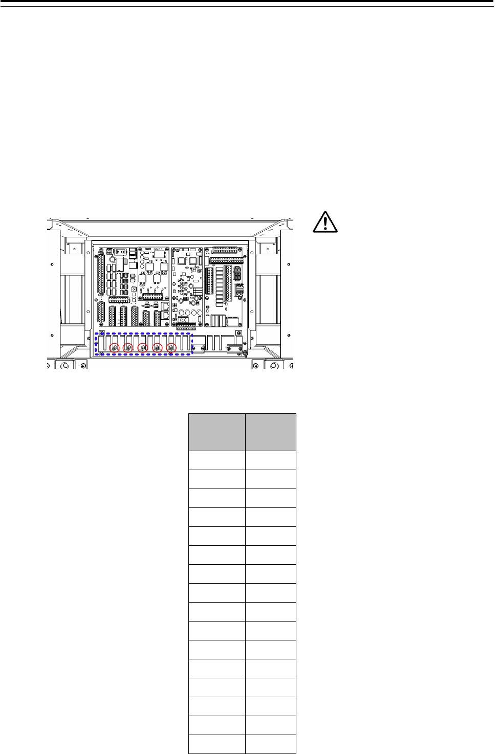
3.7.5 Contact Output
Connect the input of other equipment to the output port which is located on CMH-2370
Serial LAN interface circuit in JUNCTION BOX NQE-1143. The number of output ports on
CMH-2370 is 8 ports allocated at J8108. Terminal assign of J8108, refer to
Table 3-10:Terminal Assign of J8108.
• See Fig 3-37: Connector and TB location on CMH-2370 about location of J8108 on
CMH-2370.
• To configure the port, refer to 4.7 Setting Contacts (Contact Input/Output).
• Connect the cable shield to the hex spacer surrounded by the circle in the figure below.
(Recommended crimp terminals V5.5)
Table 3-10:Terminal Assign of J8108
Terminal
Number J8108
1 OUT1
2 RET1
3 OUT2
4 RET2
5 OUT3
6 RET3
7 OUT4
8 RET4
9 OUT5
10 RET5
11 OUT6
12 RET6
13 OUT7
14 RET7
15 OUT8
16 RET8
So that the braided shield is not shorted
to the power supply terminal block,
please insulate the cable and fix with
cable tie. Please put the Extra length of
the cable to the bottom of the display
unit so that the not shorted to the UPS
or SENSOR LAN switch unit.
3 Installation of Display Unit > 3.7 Connection with Sensors
3-116
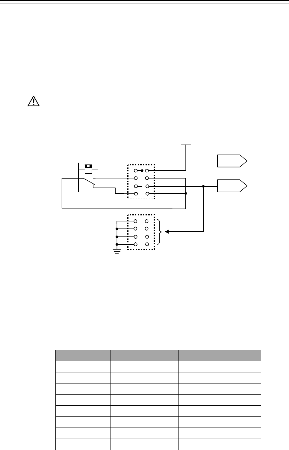
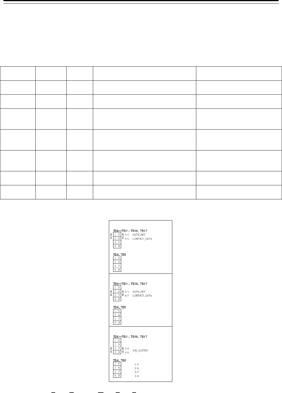
Each output port can be selected matched interface for your input device as below by
setting TB4-TB11, TB16 and TB17 shown in.
- Dry contact: Normally Open
- Dry contact: Normally Close
- 24V dc for Buzzer: Normally no Supply
- 24V dc for Buzzer: Normally Supply
24V dc for buzzer will be supplied from main power supply of CMH-2370 via 15A
fuse. If you set OUT as dry contact, do not set the terminal to GND on TB4 or TB5
which is matched to OUT you want.
OUT
RET
RELAY
(
SPDT
)
24V
TB4
o
r TB
5
Connected to matched
TB6-TB11, TB16 and
1
2
3
4
5
6
7
8
8
7
6
5
4
3
2
1
Fig 3-35 Contact output circuit diagram
Matched TB for each OUT and RET is shown in Table 3-11 Output port and setting
jumper.
And to select Output, the terminals of each TB will be set by Short plugs shown in Fig
3-36: Output port setting by TB.
Table 3-11 Output port and setting jumper
Port Jumper No. 24VDC Power GND
OUT1/RET1 TB6 TB4: short circuit 1 and 5
OUT2/RET2 TB7 TB4: short circuit 2 and 6
OUT3/RET3 TB8 TB4: short circuit 3 and 7
OUT4/RET4 TB9 TB4: short circuit 4 and 8
OUT5/RET5 TB17 TB5: short circuit 1 and 5
OUT6/RET6 TB16 TB5: short circuit 2 and 6
OUT7/RET7 TB11 TB5: short circuit 3 and 7
OUT8/RET8 TB10 TB5: short circuit 4 and 8
TB6-TB11, TB16 and TB17
3 Installation of Display Unit > 3.7 Connection with Sensors
3-117
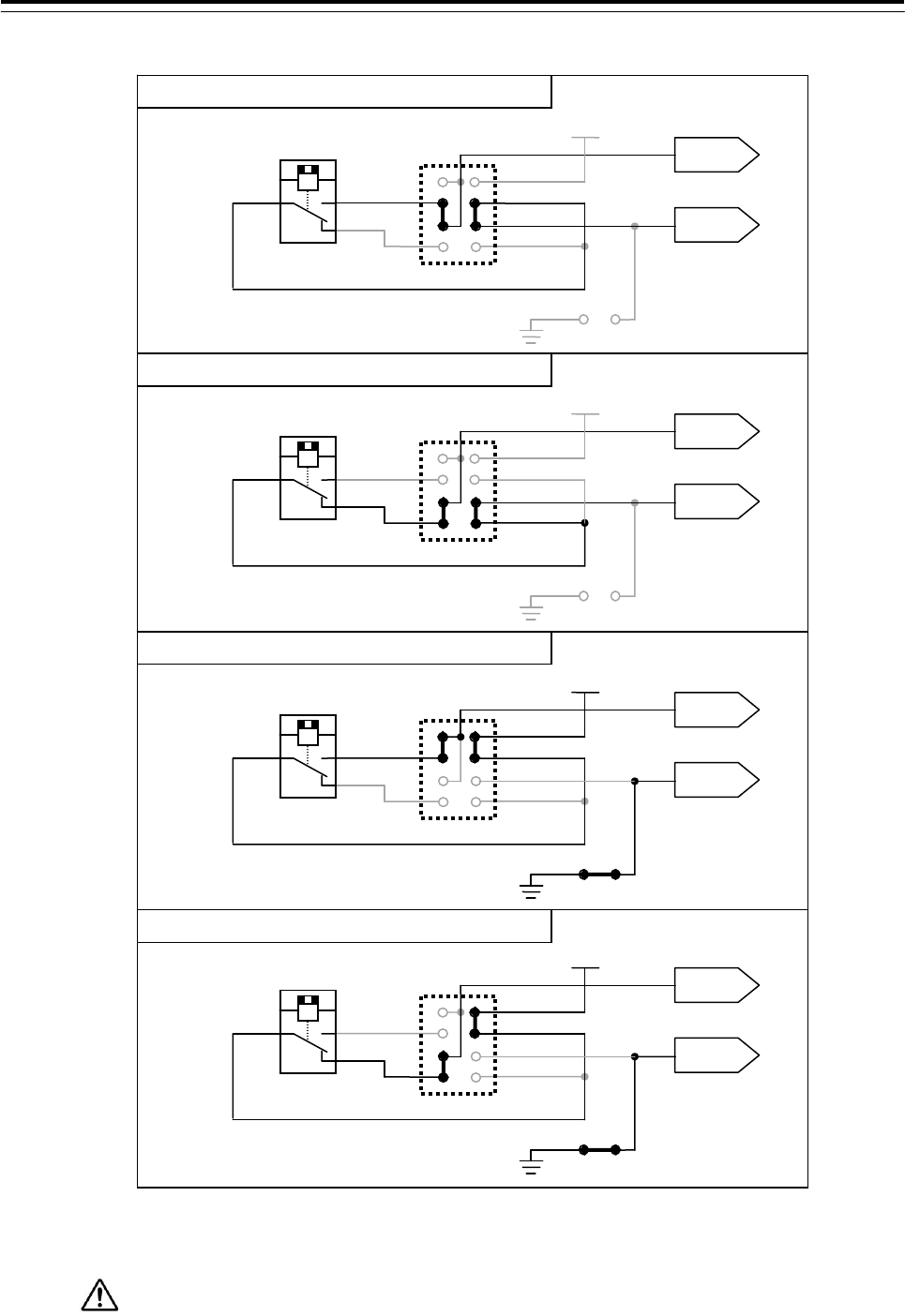
Fig 3-36: Output port setting by TB
Maximum current of RELAY is 2A.
Do not connect the load including inrush current which exceed maximum current.
OUT
RET
RELAY
(
SPDT
)
24V
TB4 or TB5
TB6-TB11, TB16 and TB17
1
2
3
4
5
6
7
8
OUT
RET
RELAY
(
SPDT
)
24V
TB4 or TB5
TB6-TB11, TB16 and TB17
1
2
3
4
5
6
7
8
OUT
RET
RELAY
(
SPDT
)
24V
TB4 or TB5
TB6-TB11, TB16 and TB17
1
2
3
4
5
6
7
8
OUT
RET
RELAY
(
SPDT
)
24V
TB4 or TB5
TB6-TB11, TB16 and TB17
1
2
3
4
5
6
7
8
Dry contact output: Normally Open
Dr
y
contact output: Normall
y
Close
24V dc supply for Buzzer: Normally no Supply
24V dc supply for Buzzer: Normally Supply
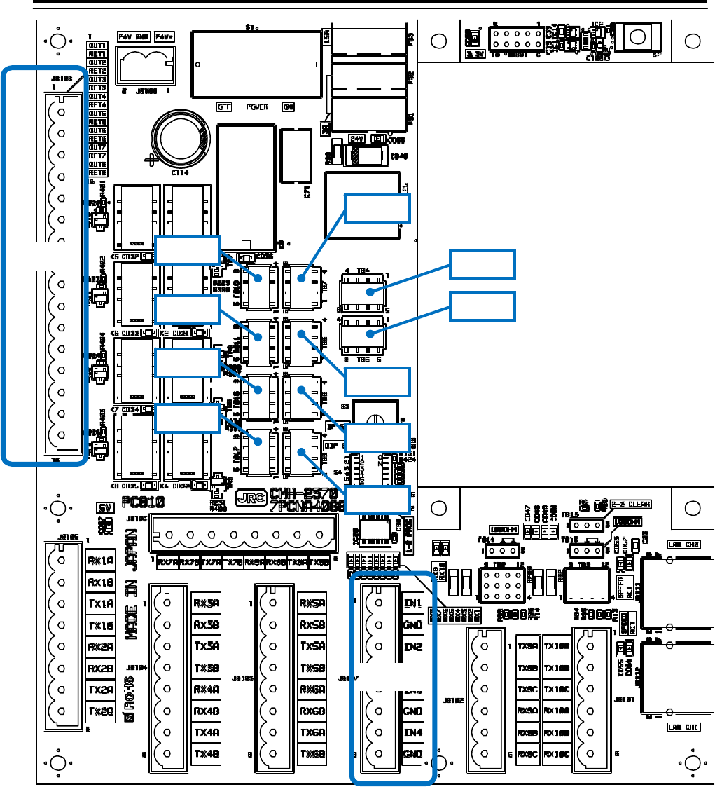
3 Installation of Display Unit > 3.7 Connection with Sensors
3-118
Fig 3-37: Connector and TB location on CMH-2370
J8108
J8107
TB3
TB5
TB4
TB7
TB6
TB10
TB11
TB16
TB17
TB8
TB9
3 Installation of Display Unit > 3.7 Connection with Sensors
3-119
3.7.6 Connections with Gyro Compasses and Electromagnetic Speed Logs
Signals from Gyro compass should be connected to J823 (1/R1, 2/S1, 3/S2, S3 and 5/R2) of CMJ-554 Gyro
Interface Circuit in the Display Unit.
Connect each Gyro Signals as follows.
Synchro-type GYROs: R1, S1, S2, S3 and R2.
Step-type GYROs: 1, 2, 3 and 5 (5 for Common)
Connect a Gyro equipment or equivalent that provided a below turn rate and an above update rate,
otherwise the performance of signal process and target tracking decrease.
turn rate update rate
Standard craft 12°/sec 40Hz
High speed craft 20°/sec 40Hz
A Signal from LOG should be connected to J823 (P+, P-) of CMJ-554 Gyro Interface Circuit in the Display
Unit. Connect a LOG Signal as follows.
Pulse-type LOGs : P+, P-
• Connect the cable shield to the hex spacer surrounded by the circle in the figure below.
(Recommended crimp terminals V5.5)
So that the braided shield is not shorted to the power supply terminal block, please insulate
the cable and fix with cable tie. Please put the Extra length of the cable to the bottom of the display
unit so that the not shorted to the UPS or SENSOR LAN switch unit.
After connecting, refer to the 3.7.7 Settings for CMJ-554 GYRO I/F Circuit for setting.
3 Installation of Display Unit > 3.7 Connection with Sensors
3-120
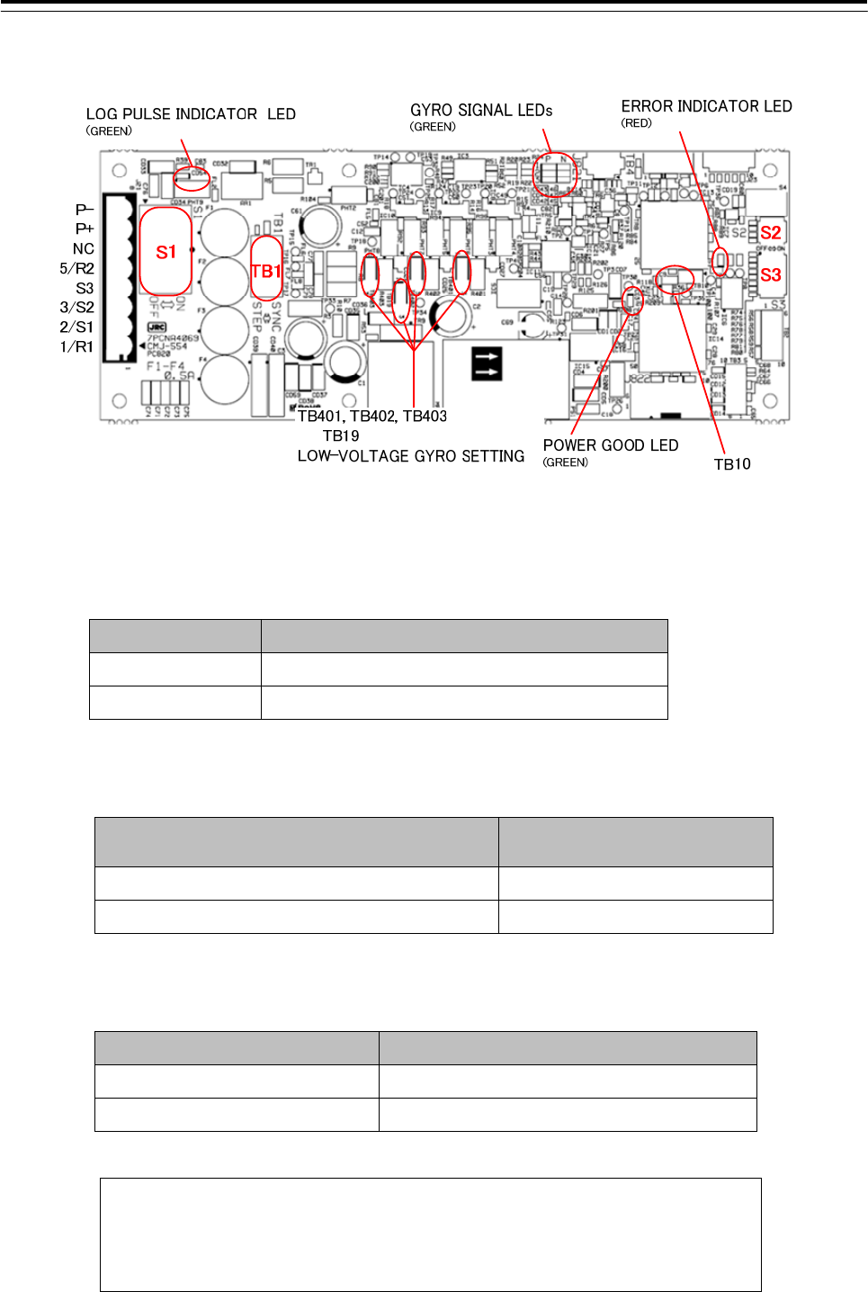
3.7.7 Settings for CMJ-554 GYRO I/F Circuit
Fig 3-38: CMJ-554 Gyro Interface Circuit
Table 3-12 Setting table of Gyro Interface Circuit
TB1 Settings Description
SYNC Synchro type Gyro compass
STEP Step type Gyro compass
Table 3-13 Setting table of Gyro Interface Circuit TB401, TB402, TB403, TB19
TB401, TB402, TB403, TB19 Settings Description
1-2 SHORT CIRCUIT Factory default
2-3 SHORT CIRCUIT Low voltage settings
Table 3-14 Setting table of Gyro Interface Circuit TB10
TB10 Settings Description
SHORT CIRCUIT Factory default
OPEN Not allowed
NOTE: If it is not suggested from JRC office, do not set “OPEN” the TB10 of
Gyro Interface Circuit.
•It may cause a lower radar system performance.
3 Installation of Display Unit > 3.7 Connection with Sensors
3-121
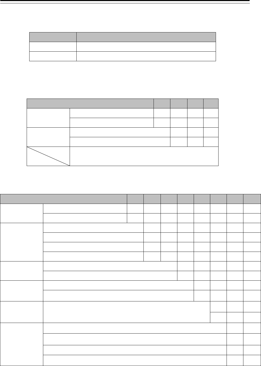
Table 3-15 Setting table of Gyro Interface Circuit S1
S1 Settings Description
OFF Gyro signals will be disconnected.
ON Gyro signals will be connected.
Table 3-16 Setting table of Gyro Interface Circuit S2
S2 SETTINGS 1 2 3 4
GYRO SIM Simulator ON ON
Simulator OFF OFF
LOG SIM Simulator ON ON
Simulator OFF ON
NC
Table 3-17 Setting table of Gyro Interface Circuit S3
S3 SETTINGS 1234 5 6 7 8
GYRO
SETTING
GYRO TYPE "STEP" ON
GYRO TYPE "SYNC" OFF
GYRO RATIO
RATIO 36x ON ON
RATIO 90x ON OFF
RATIO 180x OFF ON
RATIO 360x OFF OFF
GYRO
DIRECTION
Direction 'REVERSE' ON
Direction 'NORMAL' OFF
GYRO ALARM
TIME
LONG ON
SHORT OFF
LOG ALARM LOG ALARM
ON
OFF
LOG
SETTING
RATIO 100P ON ON
RATIO 200P ON OFF
RATIO 400P OFF ON
RATIO 800P OFF OFF

3 Installation of Display Unit > 3.7 Connection with Sensors
3-122
Connection procedure with Gyro compass
1) Turn S1 off.
Gyro Compass and Gyro Interface Circuit will be disconnected.
2) Switch the TB1 for the type of your Gyro compass.
Synchro-type Gyro Compass: Set TB1 to “SYNC”
Step-type Gyro Compass: Set TB1 to “STEP”
3) Set S3 for your Gyro compass and Speed log according to S3 Table 3-17 Setting table of Gyro
Interface Circuit S3.
S3-1 : Gyro Setting (STEP / SYNC)
S3-2/3 : Gyro Ratio
S3-4 : The direction of rotation
S3-5 : Gyro alarm time (LONG / SHORT)
S3-6 : Log alarm (ON / OFF)
S3-7/8 : Log setting
4) Set TB401, TB402, TB403 and TB19 as follows if your Gyro compass signals are less than
22V. .
1-2 SHORT CIRCUIT: Factory default.
2-3 SHORT CIRCUIT: Set this if voltages of Gyro signals are less than 22V.
5) Connect your Gyro compass and Speed log to J823 of CMJ-554 Gyro interface circuit as
follows.
Table 3-18 Output Port of Gyro Interface Circuit
Gyro and Log J823 Description
Synchro Gyro R1, S1, S2, S3 and R2. 24 - 115Vac
(50 / 60 / 400Hz)
Step Gyro 1, 2, 3 and 5 ( 5 for common ) 21.6 - 70V
Pulse Log P+, P- 0-50V, Vth = 2V.
(5V, 1k ohm Internal Pull-up)
6) Turn S1 on.
Your Gyro Compass will be connected to Gyro Interface Circuit.
7) Check your radar echo and true bearing value to make sure that your gyro compass is working
correctly.
8) Set S3-4 “Reverse” if your radar echo and true bearing have reverse rotation.
3 Installation of Display Unit > 3.7 Connection with Sensors
3-123
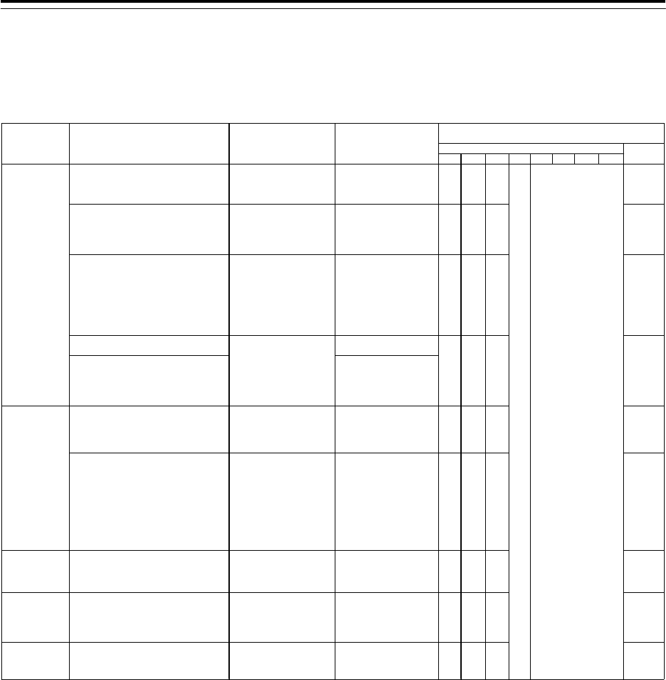
Setting Examples for some Gyro Compasses
item
Manufacture 1 2 3456 7 8
ES-2/11
GLT-100~103/105/106K/107/1104,
NJZ-501(R501)
Synchro Motor
INMS
(TS63N7E13)
(36X)
115V AC
60Hz OFF ON ON SYNC
ES-11A, GM-11/11A/21/110/120,
MS-2000/3000
PR-222R/226/237/237-L
/1*8*/2022/2023/22**,
TG-200
Synchro Motor
TSAN60E11
(90X)
110V AC
60Hz OFF OFF ON SYNC
GLT-201/202/203,
MK-14/14T,
MKE-1/14T,
MOD-1/2/T,
PR-500/2502/2503/2507/2507L
/3507/4507/5507,
SR-130/140,
TG-100/5000
Step Motor
GA-2001G
Drawing# 103590810
600 excitation
(180X)
70V DC ON ON OFF STEP
ES-16
SR-120/220 35V DC
CMZ-700D
ES140/160
PR-26**/6*6*/6*7*,
SR-140/160
TG-6000/8000
24V DC
C-1A/2/3/E,
HOKUSHIN PLATH-55/C,
PLATH HKRK-C3
Synchro Motor
YM-14
TS-19
(360X)
60V AC
60Hz OFF OFF OFF SYNC
C1JR, C-1JUNIOR,
CMZ-200A/300,
D-1,
IPS, IPS-2-H2/2B/2B-H2C/5,
KM008, KR-053,
PLATH NAVIGAT-1,
PT11-H2/21/21-H2
Synchro Motor
PY76-N2
(360X)
100V AC
50/60Hz OFF OFF OFF SYNC
アーマーブラウン
ARMA BROWN
(France)
1351,
MK-1~7/10/20, MKL-1,
NOD-4, NB-23-88,
SERIE, SGB-1000
Step Motor
BZ-2191
(180X)
50V DC ON ON OFF STEP
アンシッツ
ANSCHUTZ
(Germany)
110-301, 139-31,
ANSCHUTZ-1~6/12/14/Z,
GM-BH, K8051,
NB23-126, Z0658U
Synchro Motor
NB23-91
(360X)
50V AC
50Hz OFF OFF OFF SYNC
プラート社
C. PLATH
(Germany)
NAVIGAT 763-331E,
PLATH NAVIGAT-II/III
Synchro Motor
YM14A
(360X)
50V AC
50Hz OFF OFF OFF SYNC
*:Numeric Number
STEP
S3 settings TB1
setting
Gyro Compasses Repeater Motors
(For reference only) Excitation Voltage
Gyro Select Swiches
(S3, TB1 located on the CMJ-554)
OFF
東京計器
TOKYO KEIKI
(JAPAN)
スペリー
Sperry
(U.S.A)
横河電機
YOKOGAWA
(JAPAN)
Step Motor
GA-2001G
Drawing# 103590820
150 excitation
(180X)
ON ON OFF
3 Installation of Display Unit > 3.7 Connection with Sensors
3-124
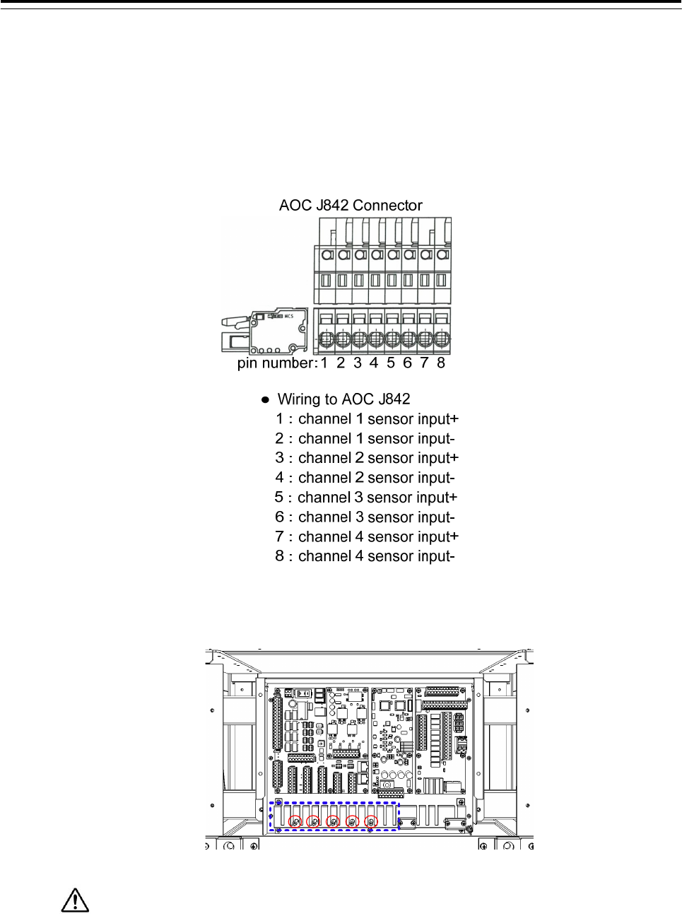
3.7.8 Connection with Analog Sensors
CMJ-560(AOC) should be connected to TB801 of CMH-2370(SLC) when connecting the Analog
Sensors. CMJ-560 can connect to 4 Analog Sensors.
Analog Sensors should be connected to J842 (Ch1:1-2pins, Ch2:3-4pins, Ch3:5-6pins,
Ch4:7-8pins).
• Connect the cable shield to the hex spacer surrounded by the circle in the figure below.
(Recommended crimp terminals V5.5)
So that the braided shield is not shorted to the power supply terminal block, please insulate
the cable and fix with cable tie. Please put the Extra length of the cable to the bottom of the display
unit so that the not shorted to the UPS or SENSOR LAN switch unit.
Set the TB2-TB7, refer to the description from the next page.
3 Installation of Display Unit > 3.7 Connection with Sensors
3-125
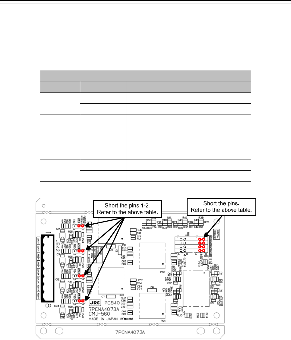
According to the output specifications of Analog Sensors, set as follows.
【Setting for Voltage Signal Input】
When Analog Sensors output specifications is Voltage, set as follows.
・Input Signal Range :-10V~+10V
Setting Table of Voltage Signal Input
Channel Reference Setting
1
TB2 Short-circuit the pins 1-2 or Open all pins
TB7 Short-circuit the pins 1-5
2 TB3 Short-circuit the pins 1-2 or Open all pins
TB7 Short-circuit the pins 2-6
3 TB4 Short-circuit the pins 1-2 or Open all pins
TB7 Short-circuit the pins 3-7
4 TB5 Short-circuit the pins 1-2 or Open all pins
TB7 Short-circuit the pins 4-8
3 Installation of Display Unit > 3.7 Connection with Sensors
3-126
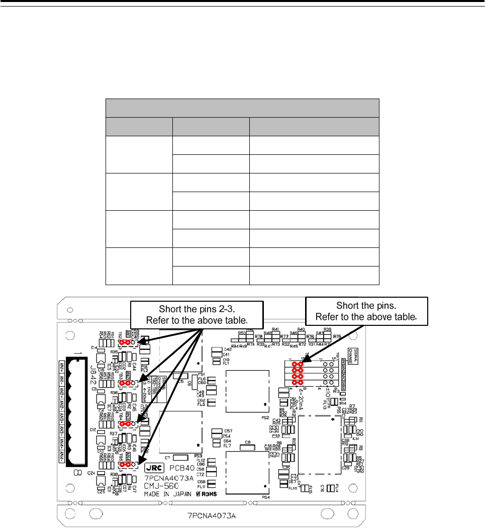
【Setting for Current Signal Input】
When Analog Sensors output specifications is Current, set as follows.
・Input Signal Range :4mA~20mA
Setting Table of Current Signal Input
Channel Reference Setting
1 TB2 Short-circuit the pins 2-3
TB6 Short-circuit the pins 1-5
2 TB3 Short-circuit the pins 2-3
TB6 Short-circuit the pins 2-6
3 TB4 Short-circuit the pins 2-3
TB6 Short-circuit the pins 3-7
4 TB5 Short-circuit the pins 2-3
TB6 Short-circuit the pins 4-8
3 Installation of Display Unit > 3.7 Connection with Sensors
3-127
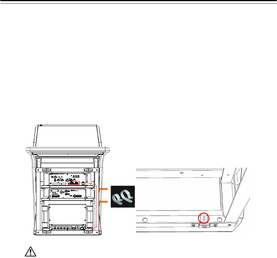
3.7.9 Backup of sensor signal
There is a receiving port (J4302, J4303) for sensor signal backup on the NDC-1590 Center Control
Unit. Wire as follows if necessary.
1)Strip the signal cable exterior about 80cm. And wire as shown in the figure below.
2)Fix the cable to the cable tie clip by the two point refer to shown below.(Refer to figure below)
3)Crimp a round terminal to the cable shield. (Recommended crimp terminals V5.5) And fix it to the
bolt on the bottom of the frame.
So that the braided shield is not shorted to the power supply terminal block, please insulate
the cable and fix with cable tie. Please put the Extra length of the cable to the bottom of the display
unit so that the not shorted to the UPS or SENSOR LAN switch unit.
Please connect the sensor to refer to the table on the next page.
3 Installation of Display Unit > 3.7 Connection with Sensors
3-128
Table 3-19 Terminal assign of J4303
Signal Name I/O Specification Detail
GPS-RX
A IN IEC61162-1 A
GPS backup signal
B IN IEC61162-1 B
SDME-RX
A IN IEC61162-1 A
SDME backup signal
B IN IEC61162-1 B
PWR FAIL
+ ― Contact out
Normal-Close Refer to 3.10
Connection with
BNWAS
- ―
WMRST
+ ― Contact out
Normal-Open
- ―
Fig 3-39 IEC61162-1 Input circuit diagram
IEC61162-1 A
IEC61162-1 B
3 Installation of Display Unit > 3.7 Connection with Sensors
3-129
Table 3-20 Terminal assign of J4302
Signal Name I/O Specification Detail
AIS-RX
A IN IEC61162-2 A
AIS backup signal B IN IEC61162-2 B
C ― IEC61162-2 C
GYRO-RX
A IN IEC61162-2 A
GYRO backup
signal
B IN IEC61162-2 B
C ― IEC61162-2 C
Fig 3-40 IEC61162-2 Input circuit diagram
IEC61162-2 A
IEC61162-2 B
IEC61162-2 C
3 Installation of Display Unit > 3.8 Connection with ECDIS
3-130
3.8 Connection with ECDIS
3.8.1 Radar Overlay
Connection for the radar overlay is different depending on the presence or absence of NQE-3141
inter-switch.
Interswitch
Connection of JMR-9200/7200 Series
and JAN-9201,JAN-7201
Connection of JMR-9200/7200Series and
JAN-901/901M/701, JAN-2000
or third party ECDIS.
When there is no
interswitch
(Can connect only one
ECDIS)
Connect the CQD-2273 Radar I/F Circuit
J836 EX_OUT(RADAR side) and
J832 SCANNER(ECDIS side).
Refer to the below figure.
Connect the CQD-2273 Radar I/F circuit
J836 EX_OUT(RADAR side)
VD+_OUT, VD-_OUT,
TRG+_OUT, TRG-_OUT,
BP+_OUT, BP-_OUT,
BZ+_OUT, BZ-_OUT and
VD,TRG,BP,BZ signal input terminal
(ECDIS side).
When there is a
interswitch
(Can connect two or
more ECDIS)
Connect via the NQE-3141-4A/8A Interswitch.
Refer to the 5.1 Installation of Interswitch Unit and 5.1.3 NQE-3141-4A Inter-board
connection diagram.
When do the radar overlay without interswitch, connect the VD, TRG, BP, BZ terminal as follow.
RADAR-ECDIS connection diagram for Radar overlay(without interswitch)
When need to connect the two or more ECDIS, use the interswitch.

3 Installation of Display Unit > 3.8 Connection with ECDIS
3-131
3.8.2 Target Tracking
Connection for the target tracking is different depending on the ECDIS model. Refer to the below table.
Receiver of the target
tracking information
Output
Specification
Connection
JAN-9201, JAN-7201 LAN
Connect the RADAR output the target tracking information and
ECDIS via the NQA-2443 SENSOR LAN SW.
JAN-901B/701B,
JAN-901/901M/701,
JAN-2000
or third party ECDIS
Serial
Target tracking information is output from CMH-2370 Serial LAN
interface circuit(RADAR side).
Connect the CMH-2370 and ECDIS with the Serial.
On both the LAN and Serial, need to set the software. Refer to Chapter4 Initial Setting.
3 Installation of Display Unit > 3.9 Connection with RADAR
3-132
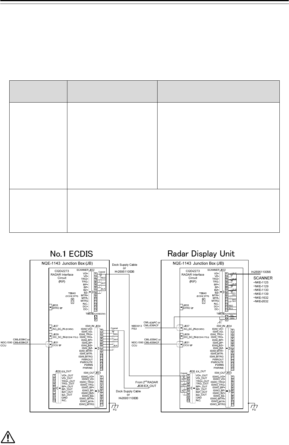
3.9 Connection with RADAR
3.9.1 Radar Overlay
When the JMA-9100/7100, JMA-5300MK2, JMA-900B or third party RADAR overlay the echo to the
JAN-9201.7201, connection for the radar overlay is different depending on the presence or absence of
NQE-3141 inter-switch. Refer to the below table.
Interswitch
Connection of JAN-9201/7201 and
JMR-9200/7200Series
Connection of JAN-9201/7201 and JMA-9100/7100,
JMA5300MK2, JMA-900B or third party RADAR
When there is no
interswitch
(Can connect Maximum
two ECDIS)
Connect the CQD-2273 Radar I/F
circuit J836 EX_OUT(RADAR side)
and J832 SCANNER(ECDIS side)
Second ECDIS:
Connect to the
J834 ISW_IN(ECDIS side)
(Refer to figure below)
Connect the CQD-2273 Radar I/F circuit
VD, TRG ,BP ,BZ output terminal and
J832 SCANNER(ECDIS side)
VD+,VD-,TRG+,TRG-,BP+,BP-,BZ+,BZ-.
Second ECDIS:
Connect to the J832 ISW_IN(ECDIS side)
ISWI_VD+, ISWI _VD-, ISWI _TRG+, ISWI _TRG-,
ISWI _BP+, ISWI _BP-, ISWI _BZ+, ISWI _BZ-.
When there is a
interswitch
(Can connect two or
more RADAR)
Connect via the NQE-3141-4A/8A Interswitch.
Refer to the 5.1 Installation of Interswitch Unit and 5.1.3 NQE-3141-4A Inter-board
connection diagram.
Third party RADAR cannot connect to the Interswitch.
When do the radar overlay without interswitch, connect the VD, TRG, BP, BZ terminal as follow.
RADAR-ECDIS connection diagram for Radar overlay(without interswitch)
When need to connect the three or more RADAR, use the interswitch.

3 Installation of Display Unit > 3.9 Connection with RADAR
3-133
3.9.2 Target Tracking
Connection for the target tracking is different depending on the RADAR model. Refer to the below table.
Receiver of the target
tracking information
Output
Specification
Connection
JMR-9200/7200 Series LAN
Connect the RADAR output the target tracking information and
ECDIS via the NQA-2443 SENSOR LAN SW.
JMA-9100/7100,
JMA-5300MK2, JMA-900B
or Third party RADAR
Serial
Connect the target tracking information from JMA-9100/7100,
JMA-5300MK2, JMA-900B or third party RADAR to the IEC61162-1
RX terminal on the SLC(ECDIS side).
On both the LAN and Serial, need to set the software. Refer to Chapter4 Initial Setting.
3 Installation of Display Unit > 3.10 Connection with BNWAS
3-134
3.10 Connection with BNWAS
The display unit of this product has the function to input/output the various contact signals for the Bridge
Navigational Watch Alarm System (BNWAS*). Connect necessary signals by referring to the table below.
Terminal
block
Signal
name Direction Description Notes
CMH-2370
SLC J8108
SYS ALM OUT System alarm status is outputted. Set to jumper normal open or
Close *1
CMH-2370
SLC J8108
ARPA
ALM
OUT Dangerous ship alarm status is outputted. Set to jumper normal open or
Close *1
NDC-1590
J4303
PWR FAIL OUT AC Low Voltage is detected.
DC24V must be connected to NBD-913 for
system backup.
Normal-Close
CMH-2370
SLC J8107
SYS ACK IN Acknowledge input of system alarm. “False” indicates Open or
Disconnection and “True” indicates
Closed.
CMH-2370
SLC J8107
ARPA
ACK
IN Acknowledge input of Dangerous ship
alarm.
“False” indicates Open or
Disconnection and “True” indicates
Closed.
CMH-2370
SLC J8108
ACK OUT OUT Acknowledge output of alarms. Set to jumper normal open or
Close *1
NDC-1590
J4303
WMRST OUT Watch Man alarm reset signal. Normal-Open
*1 Serial LAN interface circuit jumper setting
(*) BNWAS Bridge Navigation Watch Alarm System
Normal Close Setting
Normal Open Setting
24V Out Setting

3 Installation of Display Unit > 3.11 Ground Connection
3-135
3.11 Ground Connection
All sorts of pulse circuits are built in this equipment. They radiate a high-frequency component of
Pulse wave as an electromagnetic wave from their circuit itself or cables between the equipment
And might interfere as receiver noise by connecting with a receiving antenna or cable of radio
Communication equipment. A general effective method is shown as follows as a measure to
counter interference for this kind of case.
3.11.1 Shield for Equipment
Covers for the purpose of shielding are installed where they are necessary on each component of
this equipment. Tighten up screws on the equipment thoroughly not to reduce their effect.
3.11.2 Cables for Equipment
Always use specified cables for the connection between components.
Pay enough attention to the connection of cables and processing their end portion.
So that the braided shield is not shorted to the power supply terminal block, please insulate the cable and fix
with cable tie. Please put the Extra length of the cable to the bottom of the display unit so that the not shorted
to the UPS or SENSOR LAN switch unit.
3.11.3 Mounting Location
The equipment is shielded sufficiently, but not completely. Set up very carefully a surrounding
cable etc. when you set up the equipment.
3.11.4 Grounding
Ground the equipment to the nearest hull earth terminal thought it might not be an effective method
because the state changes considerably by the structure of the hull and the position of radio
equipment in relation to this equipment. At the same time, ground the problematic radio equipment
by the shortest distance, too
When installing the stand alone type, copper plate have been attached to the Display Unit Mount Kit.
Fasten the copper plate to the unpainted position surrounded by the circle in the figure below and
ground the copper plate to the hull earth.
Display Unit Mount Kit grounding position
3 Installation of Display Unit > 3.12 Installation of Power Cable
3-136
3.12 Installation of Power Cable
Before installing power cable, always make sure to turn off the circuit
breaker of main power line. Otherwise, it may cause an electric shock or
malfunction.
3.12.1 Input Voltage Specification
・AC-Input
Voltage :100 to 115VAC,220 to 240VAC
Voltage ranges :85 to 264VAC
Overvoltage Protection :295VAC±2V,
Frequency :50Hz/60Hz
Input Current :Max 6.8A(100VAC)/3.4A(220VAC)
Over current Protection :equipped
・DC-input
Voltage :24VDC
Voltage ranges :21.6 to 31.2VDC
Overvoltage Protection :42V
Input Current :Max 16A
Over current Protection :equipped
3 Installation of Display Unit > 3.12 Installation of Power Cable
3-137
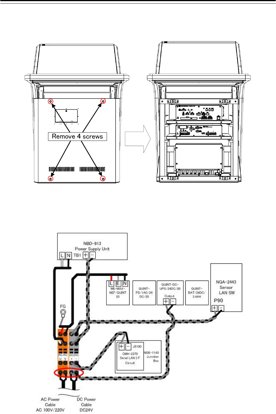
3.12.2 Connecting Power Cable
1) Remove 4 screws of the front cover in processing unit.
2) After confirming the circuit breaker of the main power line is “OFF”, connect the AC power cable to the
AC-U and AC-V terminal on the CQD-2312 Relay terminal. Also, DC power cable connect to the DC+ and
DC- terminal on the Relay terminal. Refer to figure below.
3 Installation of Display Unit > 3.13 Initialization for the specified model
3-138
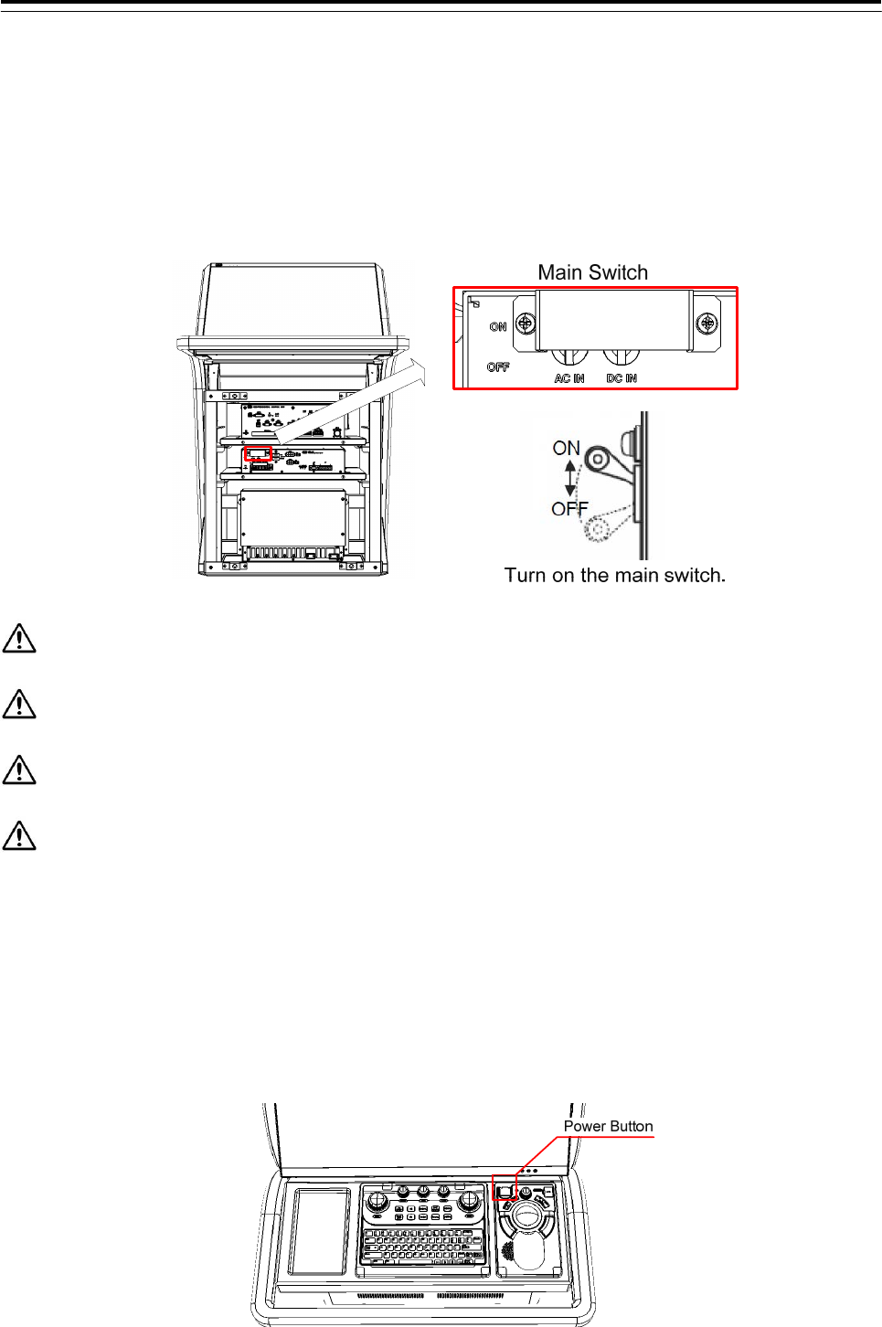
3.13 Initialization for the specified model
The initialization of the following is necessary to use when the equipment will be shipped from the stock of the
each unit. Turn on the AC/DC circuit breaker (refer to the figure below). And proceed to Chapter 4.
1) Connect the USB flash drive included initialization tool to the Display Unit. And turn on both AC and DC.
Before turn on the Display Unit, please make sure that wired correctly.
The initializaiton tool is autorun. When connect the USB flash drive, initialization tool is executed.
Can not use the USB flash drive have the security function.
For the details that how to obtain the data files for NDC-1590-CCU, please contact our head office
or a nearby branch or local office beforehand.
2) The system is turned on automatically only after the first time turning on the main switch. And after a few
seconds, the system of the power is down and up automatically. This is a normal behavior. Go to next
step.
When the system will not boot up, check the ship's main and the main switch of PSU and press the power
button on the trackball operation unit.
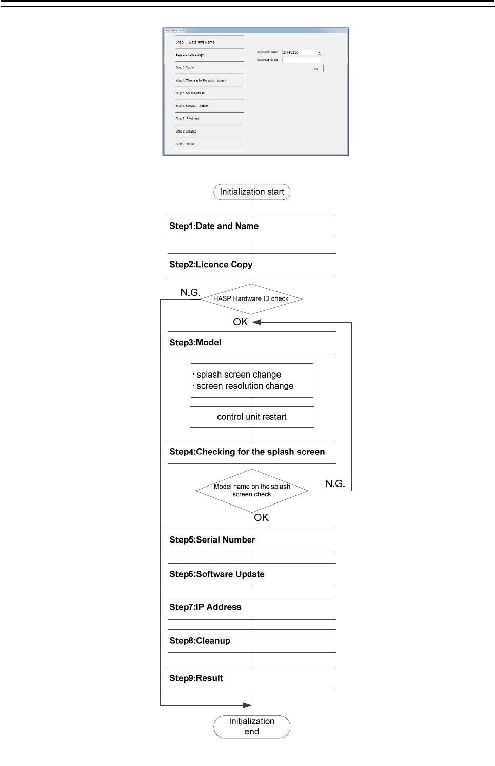
3) Initialization tool is started.
3 Installation of Display Unit > 3.13 Initialization for the specified model
3-139
3) Initialization tool is started.
The following describes the outline of Initialization tool.
3 Installation of Display Unit > 3.13 Initialization for the specified model
3-140
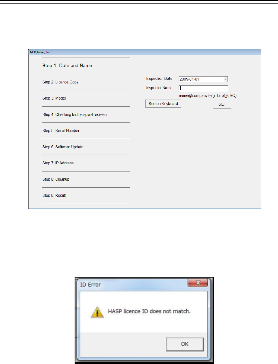
4) Initialize according to the following procedures before using the equipment.
Step1: Date and Name
Input the inspector date, inspector name. And then click the [SET] button.
Step2: Licence Copy
The Hardware ID of HASP is compared with the Hardware ID in the licence file.
If they match, the licence file is copied over.
HASP: Hardware Against Software Piracy (included NDC-1590 Central Control Unit)
If they mismatch, following dialog is displayed.
3 Installation of Display Unit > 3.13 Initialization for the specified model
3-141
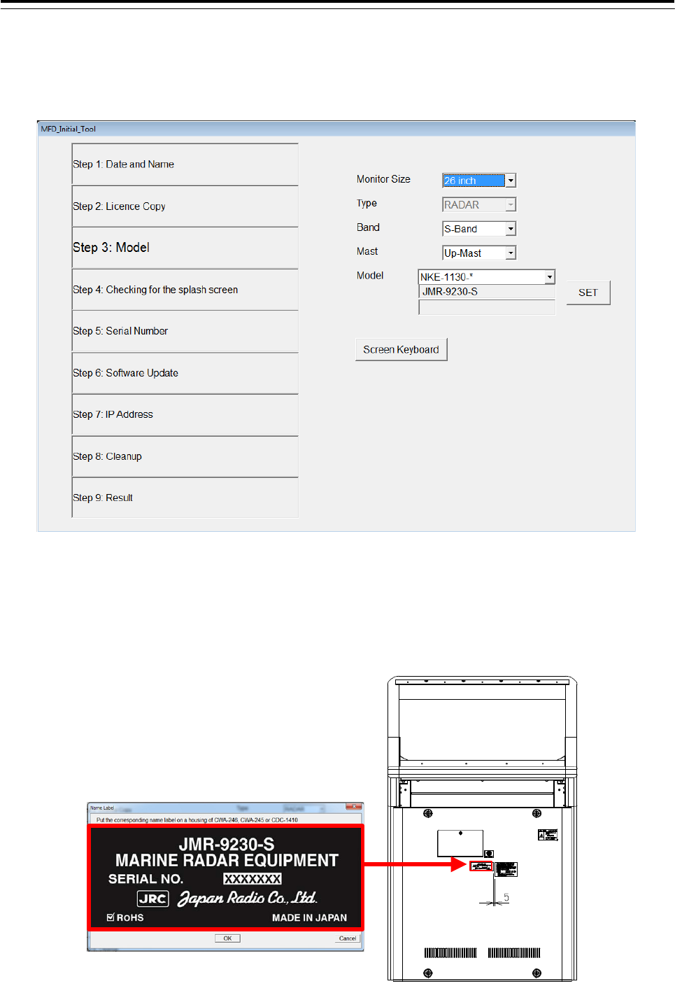
Step3: Model
Select each item from the drop-down list. Model name is displayed in the Model window. And then
click the [SET] button.
After clicking the [SET] button, the following image is displayed.
a) When installing the stand alone type
Paste the Name Label same as the image to the position shown in the figure below.
All model name label each two have been attached to the display unit. Please discard the label which model
name does not match or remained.
In case of JMR-9230-S
3 Installation of Display Unit > 3.13 Initialization for the specified model
3-142
b) When installing the desktop type or flush mount type
All model name label each two have been attached to the display unit. Paste the Name Label same as
the image to the position shown in the figure below. Back the other label of the same model name to the
bag and attach the bag to the NDC-1590. Please discard the label which model name does not match.
Name label
pasting position
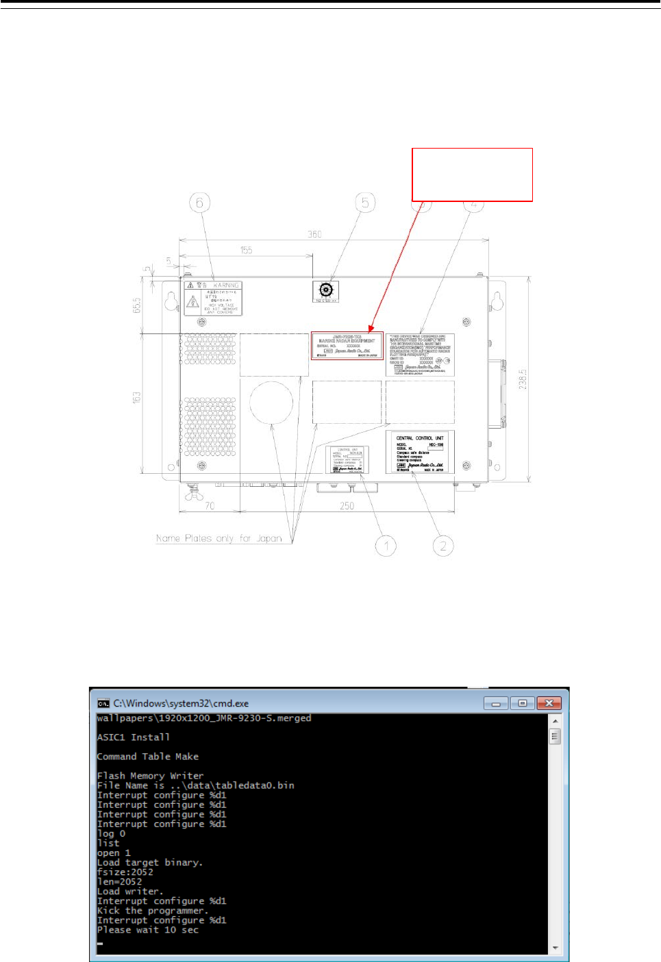
After pasting, please press the [OK] button. The following screen is displayed and start-up screen will be
changed automatically. It will take a few minutes to process. Please press any key because it is a key input
required at the end. After processing, please press any key because key input required at the end. Resolution
and splash screen is automatically changed, and then the following dialog is displayed.
3 Installation of Display Unit > 3.13 Initialization for the specified model
3-143
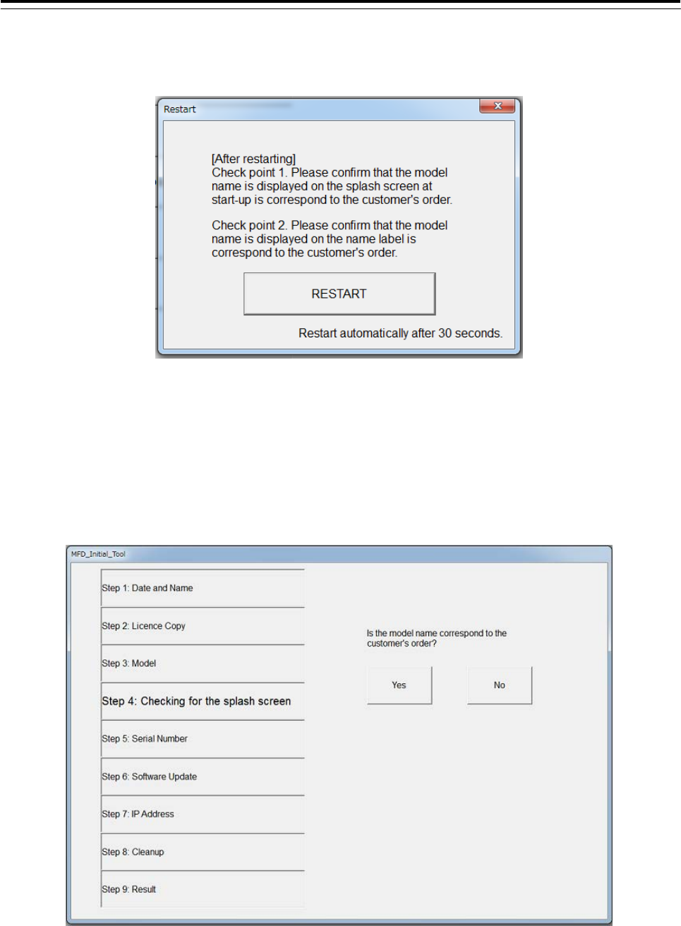
Then the following screen is displayed. Make sure that the model name that appears during a restart and
model name selected in step 3 matches.
Restart by clicking the [RESTART] button. Or restart automatically after 30 seconds.
Step4: Checking for the splash screen
After restarting, the following dialog is displayed. Confirm that the Model name displayed on the splash
screen and the Name Label pasted in step 3 is match.
● When the model name matched, click the [Yes] button. Proceed to the next step.
● When the model name mismatched, click the [No] button.
Initialization tool will return to the screen of step3. Please check the equipment information again.
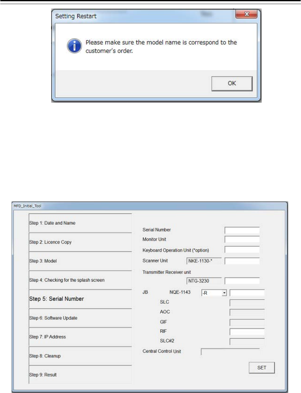
The following dialog is displayed. Peel off the Name Label pasted in step 3, and then click the [OK]
button.
3 Installation of Display Unit > 3.13 Initialization for the specified model
3-144
Step5: Serial Number
The following dialog is displayed. Input the serial number of each unit. And then click the [SET]
button.
- Please make sure that serial number and manufacturing number indicated are
matched.
- When setting the desktop type or flush mount type, may not enter the serial number of the monitor.
- When input the JB(Junction box) serial number , enter the barcode number and suffix of JB.
- May not enter the serial number of SLC, AOC, GIF, RIF, SLC#2.
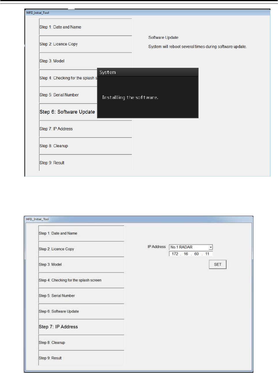
Step6: Software Update
Update is started. It takes several ,minutes. Display unit will restart several times during the
software update. This is normal behavior.
3 Installation of Display Unit > 3.13 Initialization for the specified model
3-145
Step7: IP Address
Set the IP Address by selecting the Unit No. from dropdown list, and then click the [SET] button.
Step8: Cleanup
The tool deletes unnecessary files automatically.
3 Installation of Display Unit > 3.13 Initialization for the specified model
3-146
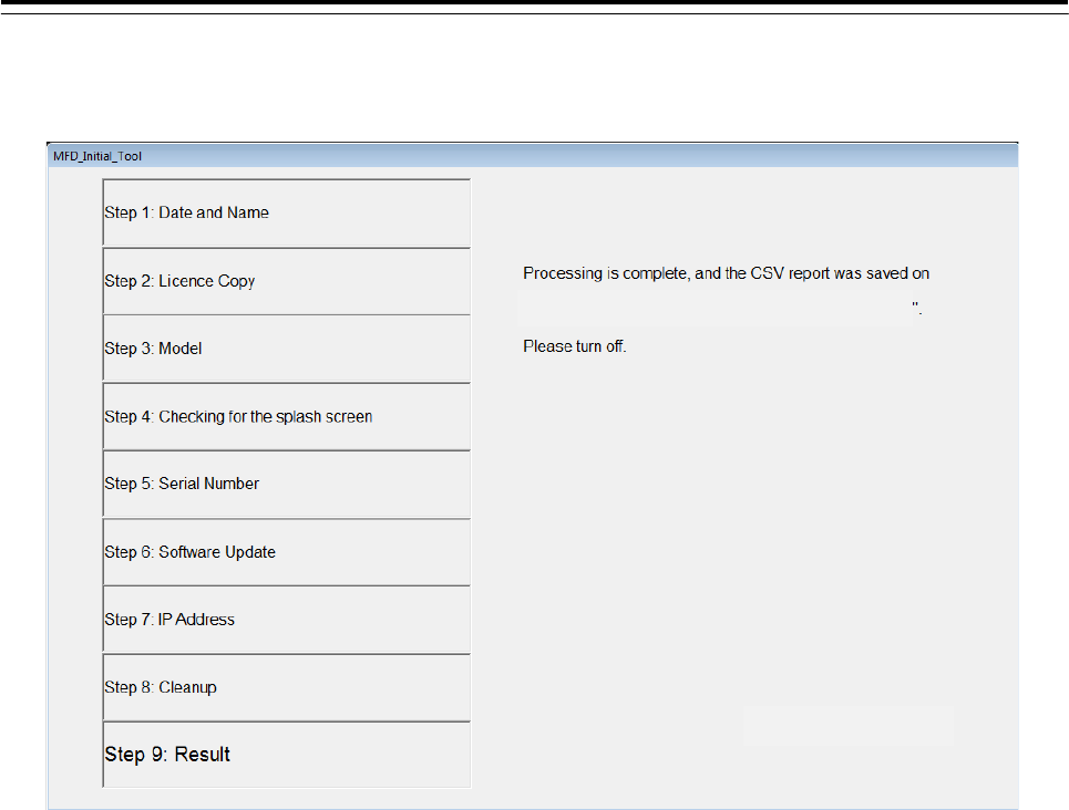
Step9: Result
Click the [FINISH] button. The resulting CSV file is output.
The initialize ends above.
[Display the path of the outputted csv file]